EP3009658A1 - Injector for injecting fluid - Google Patents
Injector for injecting fluid Download PDFInfo
- Publication number
- EP3009658A1 EP3009658A1 EP14189105.1A EP14189105A EP3009658A1 EP 3009658 A1 EP3009658 A1 EP 3009658A1 EP 14189105 A EP14189105 A EP 14189105A EP 3009658 A1 EP3009658 A1 EP 3009658A1
- Authority
- EP
- European Patent Office
- Prior art keywords
- armature
- valve needle
- injector
- pole piece
- retainer
- Prior art date
- Legal status (The legal status is an assumption and is not a legal conclusion. Google has not performed a legal analysis and makes no representation as to the accuracy of the status listed.)
- Granted
Links
Images


Classifications
-
- F—MECHANICAL ENGINEERING; LIGHTING; HEATING; WEAPONS; BLASTING
- F02—COMBUSTION ENGINES; HOT-GAS OR COMBUSTION-PRODUCT ENGINE PLANTS
- F02M—SUPPLYING COMBUSTION ENGINES IN GENERAL WITH COMBUSTIBLE MIXTURES OR CONSTITUENTS THEREOF
- F02M51/00—Fuel-injection apparatus characterised by being operated electrically
- F02M51/06—Injectors peculiar thereto with means directly operating the valve needle
- F02M51/061—Injectors peculiar thereto with means directly operating the valve needle using electromagnetic operating means
- F02M51/0625—Injectors peculiar thereto with means directly operating the valve needle using electromagnetic operating means characterised by arrangement of mobile armatures
- F02M51/0632—Injectors peculiar thereto with means directly operating the valve needle using electromagnetic operating means characterised by arrangement of mobile armatures having a spherically or partly spherically shaped armature, e.g. acting as valve body
-
- F—MECHANICAL ENGINEERING; LIGHTING; HEATING; WEAPONS; BLASTING
- F02—COMBUSTION ENGINES; HOT-GAS OR COMBUSTION-PRODUCT ENGINE PLANTS
- F02M—SUPPLYING COMBUSTION ENGINES IN GENERAL WITH COMBUSTIBLE MIXTURES OR CONSTITUENTS THEREOF
- F02M51/00—Fuel-injection apparatus characterised by being operated electrically
- F02M51/06—Injectors peculiar thereto with means directly operating the valve needle
- F02M51/061—Injectors peculiar thereto with means directly operating the valve needle using electromagnetic operating means
- F02M51/0625—Injectors peculiar thereto with means directly operating the valve needle using electromagnetic operating means characterised by arrangement of mobile armatures
- F02M51/0664—Injectors peculiar thereto with means directly operating the valve needle using electromagnetic operating means characterised by arrangement of mobile armatures having a cylindrically or partly cylindrically shaped armature, e.g. entering the winding; having a plate-shaped or undulated armature entering the winding
- F02M51/0685—Injectors peculiar thereto with means directly operating the valve needle using electromagnetic operating means characterised by arrangement of mobile armatures having a cylindrically or partly cylindrically shaped armature, e.g. entering the winding; having a plate-shaped or undulated armature entering the winding the armature and the valve being allowed to move relatively to each other or not being attached to each other
-
- F—MECHANICAL ENGINEERING; LIGHTING; HEATING; WEAPONS; BLASTING
- F02—COMBUSTION ENGINES; HOT-GAS OR COMBUSTION-PRODUCT ENGINE PLANTS
- F02M—SUPPLYING COMBUSTION ENGINES IN GENERAL WITH COMBUSTIBLE MIXTURES OR CONSTITUENTS THEREOF
- F02M61/00—Fuel-injectors not provided for in groups F02M39/00 - F02M57/00 or F02M67/00
- F02M61/04—Fuel-injectors not provided for in groups F02M39/00 - F02M57/00 or F02M67/00 having valves, e.g. having a plurality of valves in series
- F02M61/10—Other injectors with elongated valve bodies, i.e. of needle-valve type
- F02M61/12—Other injectors with elongated valve bodies, i.e. of needle-valve type characterised by the provision of guiding or centring means for valve bodies
-
- F—MECHANICAL ENGINEERING; LIGHTING; HEATING; WEAPONS; BLASTING
- F02—COMBUSTION ENGINES; HOT-GAS OR COMBUSTION-PRODUCT ENGINE PLANTS
- F02M—SUPPLYING COMBUSTION ENGINES IN GENERAL WITH COMBUSTIBLE MIXTURES OR CONSTITUENTS THEREOF
- F02M61/00—Fuel-injectors not provided for in groups F02M39/00 - F02M57/00 or F02M67/00
- F02M61/16—Details not provided for in, or of interest apart from, the apparatus of groups F02M61/02 - F02M61/14
- F02M61/20—Closing valves mechanically, e.g. arrangements of springs or weights or permanent magnets; Damping of valve lift
-
- F—MECHANICAL ENGINEERING; LIGHTING; HEATING; WEAPONS; BLASTING
- F02—COMBUSTION ENGINES; HOT-GAS OR COMBUSTION-PRODUCT ENGINE PLANTS
- F02M—SUPPLYING COMBUSTION ENGINES IN GENERAL WITH COMBUSTIBLE MIXTURES OR CONSTITUENTS THEREOF
- F02M2200/00—Details of fuel-injection apparatus, not otherwise provided for
- F02M2200/30—Fuel-injection apparatus having mechanical parts, the movement of which is damped
- F02M2200/304—Fuel-injection apparatus having mechanical parts, the movement of which is damped using hydraulic means
Definitions
- the invention relates to an injector for injecting fluid and relates particularly to an injector for injecting fuel into an internal combustion engine.
- Injection valves are in widespread use, in particular for internal combustion engines where they may be arranged in order to dose the fluid into an intake manifold of the internal combustion engine or directly into the combustion chamber of a cylinder of the internal combustion engine.
- injection valves are manufactured in various forms in order to satisfy the various needs for the various combustion engines. Therefore, for example, their length, diameter as well as various elements of the injection valve which are responsible for the way the fluid is dosed may vary within a wide range.
- injection valves may accommodate an actuator for actuating a valve needle of an injection valve, which may, for example, be an electromagnetic actuator.
- the respective injection valve may be suited to dose fluids under very high pressure.
- the pressure may be, in the case of a gasoline engine, for example in the range of up to 500 bar, and in the case of diesel engines in the range of up to 3500 bar.
- One object of the invention is to create an injector for injecting fluid that contributes to a controllability of an amount of injected fluid and enables efficient operation of the injector.
- the object is achieved by the features of the independent claim. Further embodiments of the invention are given in the dependent claims.
- an injector for injecting fluid comprises a valve assembly with a valve body and a valve needle.
- the valve body has a longitudinal axis and comprises a cavity with a valve seat.
- valve needle comprises an armature retainer that is coupled in a fixed way to the valve needle.
- armature retainer comprises an armature retainer constriction surface.
- the cavity is operable to take in the valve needle.
- the cavity and the valve needle are operable to prevent an injection of fluid from the cavity to external to the injector in a closing position of the valve needle, in which the valve needle is seated on the valve seat.
- the cavity and the valve needle are operable to enable the injection of fluid when the valve needle is spaced apart from the closing position.
- the injector further comprises an electromagnetic actuator assembly, which is operable to exert a force for influencing a position of the valve needle.
- the electromagnetic actuator assembly comprises a pole piece and an armature.
- the pole piece is received in the cavity and positionally fix with the valve body.
- the pole piece comprises a pole piece constriction surface facing towards the armature.
- the armature is received in the cavity and operable to be axially displaced relative to the pole piece.
- the armature is further operable to take along the armature retainer when being displaced towards the pole piece.
- a hydraulically effective restriction is formed between the armature retainer constriction surface and the pole piece constriction surface in at least a range of an axial displacement of the valve needle from a maximum displacement away from the closing position to a restriction displacement.
- the hydraulically effective restriction in particular effects a first damping force which is exerted on the valve needle.
- the "restriction displacement” is in particular an axial position of the valve needle between the closing position and that axial position which corresponds to the maximum displacement away from the closing position.
- the hydraulically effective restriction is a fluid channel which is defined by a surface of the armature retainer - which is referred to as the armature retainer constriction surface - and a surface of the pole piece - which is referred to as the pole piece constriction surface.
- the fluid channel can be also be referred to as a gap.
- a hydraulic diameter of said fluid channel is dependent on the axial displacement of the valve needle from the closing position. Specifically, the hydraulic diameter decreases with increasing displacement of the valve needle from the closing position.
- the hydraulic diameter of the fluid channel is at least twice at large - in on embodiment at least three times or four times as large - when the valve needle is in the closing position compared to the hydraulic diameter when the valve needle is at the maximum displacement away from the closing position.
- fluid which enters the cavity at a fluid inlet end of the valve body and flows to a fluid outlet end of the valve body where the valve seat is positioned has to pass through said fluid channel.
- a velocity of the valve needle is decreased by the first damping force such that an amount of injected fluid is suitably influenced.
- the first damping force contributes to a controllability of the injector in a ballistic phase of an opening phase of the injector.
- a variation of the amount of injected fluid within a given time window is kept low. In other words, it is contributed to a controllability of the amount of injected fluid.
- the restriction displacement of the valve needle away from the closing position is greater than zero; for example, it has a value of one third of the maximum displacement or more.
- the range in which the hydraulically effective restriction is formed may be greater than zero; for example, it has a value of 15 % or more, in particular of 30 % or more of the maximum displacement.
- the restriction displacement, respectively the range is dimensioned as to enable exertion of a desired damping force on the valve needle.
- it is further dimensioned such that the velocity of the valve needle is substantially uninfluenced in a first portion of the opening phase of the injector, hence enabling efficient operation of the injector.
- the armature retainer constriction surface and the pole piece constriction surface comprise a smallest distance between the pole piece and the armature retainer at least when the valve needle is axially displaced in the range from the maximum displacement away from the closing position to the restriction displacement.
- the armature retainer constriction surface and the pole piece constriction surface may comprise the smallest distance between the pole piece and the armature retainer when the valve needle is axially displaced to the maximum displacement and/or the restriction displacement.
- the maximum displacement of the valve needle away from the closing position may be reached when the valve needle is in an opening position, in which the armature abuts the pole piece.
- the armature retainer constriction surface has a first sloped shape.
- the pole piece constriction surface has a second sloped shape.
- the first and/or second sloped shape may be a conical shape, for example, in particular a truncated conical shape.
- the second sloped shape may be equally sloped to the first sloped shape; in this case, the width of the fluid channel - i.e. the distance between the two constriction surfaces - is in particular independent from a position in the fluid channel along a flow direction of the fluid through the fluid channel.
- the armature retainer constriction surface with its first sloped shape and the pole piece constriction surface with its second sloped shape face each other in order to enable a suitable formation of the hydraulically effective restriction.
- the armature retainer constriction surface has a first curvature.
- the first curvature contributes to a prevention of jamming of the armature retainer, particularly when the valve needle is tilted.
- the armature retainer is constructed convex, at least at the armature retainer constriction surface.
- the pole piece constriction surface has a second curvature.
- the second curvature contributes to a prevention of jamming of the armature retainer, particularly when the valve needle is tilted.
- the pole piece is constructed concave, at least at the pole piece constriction surface.
- the second curvature is less than or equal to the first curvature.
- the first damping force exerted on the valve needle is dependent on the position of the valve needle.
- this allows for reliably decreasing the velocity of the valve needle in order to achieve a suitably controllable amount of injected fluid, particularly within the range between the maximum displacement of the valve needle and the restriction displacement, while keeping it substantially uninfluenced in the first instant of the opening phase of the injector which contributes to an efficient operation of the injector.
- the armature retainer comprises an armature retainer guiding surface.
- the pole piece comprises a pole piece guiding surface.
- the armature retainer is operable for axially guiding the valve needle with the armature retainer guiding surface gliding along the pole piece guiding surface when the valve needle is axially displaced.
- the armature retainer has a side surface - referred to as the armature retainer guiding surface - and the pole piece has a side surface - referred to as the pole piece guiding surface - which are in sliding contact for axially guiding the valve needle.
- the axial guiding of the valve needle contributes to a prevention of tilting of the valve needle, thus enabling efficient operation of the injector.
- the armature retainer guiding surface is convexly curved with respect to the valve needle.
- a convex curvature of the armature retainer guiding surface contributes to a prevention of jamming of the armature retainer, particularly when the valve needle is tilted. Thus an efficient operation of the injector is enabled.
- the armature retainer guiding surface is substantially spherically shaped, i.e. it has the basic shape of a sphere.
- a spherical curvature of the armature retainer guiding surface contributes to a reliable prevention of jamming of the armature retainer, particularly when the valve needle is tilted, thus enabling an efficient operation of the injector.
- the armature retainer guiding surface comprises at least one axial channel for enabling a fluid flow axially through the cavity.
- the armature is axially movable relative to the valve needle.
- an axial movement of the valve needle may be decoupled from an axial movement of the armature. This for example contributes to a prevention of a transmission of an undesired bouncing of the armature to the valve needle, hence enabling efficient operation of the injector.
- the armature retainer comprises an armature retainer limiting surface for limiting an axial displacement of the armature relative to the valve needle.
- the armature retainer limiting surface is a surface of the armature retainer which faces towards the armature and laterally extends away from the valve needle.
- the armature comprises an armature impact area facing towards the armature retainer limiting surface. The armature retainer limiting surface is operable to engage with the armature impact area.
- the armature retainer is in particular operable to limit the axial displacement of the armature relative to the valve needle by means of a form-fit engagement between a surface portion of the armature - referred to as the armature impact area - and and the armature retainer limiting surface.
- the armature retainer limiting surface allows for a reliable force transmission of the armature to the valve needle.
- the armature retainer limiting surface enables the valve needle to engage with the armature and to be taken along with the armature when the armature is axially displaced towards the pole piece.
- the injector further comprises a disc element, wherein the disc element is coupled in a fixed way to the valve needle for limiting an axial displacement of the armature relative to the valve needle away from the pole piece
- the armature may be coupled to the valve needle by the disc element and the armature retainer limiting surface so that it has an axial play between the armature retainer limiting surface and the disc element.
- a lateral extension of the armature retainer limiting surface away from the valve needle is constructed such that a relative movement between the armature and the armature retainer is damped.
- the armature retainer limiting surface contributes to a prevention of bouncing of the valve needle, particularly when the armature abuts the pole piece. This contributes to an efficient operation of the injector.
- the armature impact area and the armature retainer limiting surface may be parallel.
- a lateral extension of the armature impact area away from the valve needle is constructed such that the relative movement between the armature and the armature retainer is damped.
- the lateral extension of the armature impact area may be greater than or equal to the lateral extension of the armature retainer limiting surface.
- the armature retainer limiting surface and the armature retainer constriction surface are comprised by a stopper portion of the armature retainer and on opposite axial sides of the stopper portion.
- the armature retainer limiting surface and the armature retainer constriction surface are preferably inclined or curved relative to one another in such fashion that the stopper portion tapers in radial outward direction.
- the armature retainer further has a guiding portion which comprises the armature retainer guiding surface as its outer surface or as a portion of its outer surface.
- the guiding portion may expediently be arranged on the axial side of the stopper portion which is remote from the armature and in particular merges with the stopper portion.
- the armature retainer has a constriction in a region where the guiding portion and the stopper portion merge.
- the maximum radial dimension of the stopper portion is at least twice as large as the maximum radial dimension of the guiding portion. Such dimensions are particularly advantageous for efficient damping of the relative movement between the armature and the armature retainer.
- the injector comprises a return spring, which is operable to bias the armature in axial direction away from the armature retainer.
- the armature return spring is seated in precompressed fashion against the armature retainer and the armature.
- a large impulse transfer to the valve needle is enabled when the armature comes into contact with the armature retainer. This also enables an opening of the valve needle against a large hydraulic load with only limited actuator power.
- the return spring may particularly be seated on the armature retainer limiting surface.
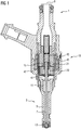
- Figure 1 shows a first embodiment of an injector 1 with a valve assembly 3 and an electromagnetic actuator assembly 19.
- the valve assembly 3 comprises a valve body 5 and a valve needle 7.
- the valve body 5 has a longitudinal axis 9 and comprises a cavity 11 with a valve seat 13.
- the valve needle 7 is received in the cavity 11 and is axially movable relative to the valve body 5.
- the valve needle 7 comprises an armature retainer 15 that is coupled in a fixed way to the valve needle 7. It may further comprise a disc element 41 being axially displaced to the armature retainer 15 and coupled in a fixed way to the valve needle 7.
- the valve needle 7 is operable to prevent an injection of fluid in a closing position, in which the valve needle 7 is seated on the valve seat 13, from the cavity 11 external to the injector 1, for example into a combustion chamber.
- the valve needle 7 is further operable to enable the injection of fluid when it is apart from the closing position.
- the injector 1 may comprise a valve spring 43 for biasing the valve needle 7 towards the closing position, for example in order to contribute to a leak tightness of the injector 1.
- the electromagnetic actuator assembly 19 comprises a pole piece 21, an armature 23 and a magnetic coil 45, in particular solenoid, positioned in a housing which laterally surrounds at least a portion of the valve body 5.
- the magnetic coil 45 together with the armature 23 and the pole piece 21 forms a magnetic circuit of the electromagnetic actuator assembly 19 when the magnetic coil 45 is energized.
- the electromagnetic actuator assembly 19 may further comprise a yoke 47 for shaping the magnetic circuit of the electromagnetic actuator assembly 19.
- the electromagnetic actuator assembly 19 is thus operable to exert a force for influencing a position of the valve needle 7.
- the valve needle 7 may be axially displaced by the electromagnetic actuator assembly 19 relative to the valve body 5, for example in reciprocating fashion.
- Figure 2 shows an enlarged longitudinal section view of the injector according to figure 1 , particularly of the electromagnetic actuator assembly 19.
- the pole piece 21 is received in the cavity 11 and positionally fix with the valve body 5.
- the pole piece 21 may be comprised by the valve body 5.
- the armature 23 is received in the cavity 11 and operable to be axially displaced relative to the pole piece 21.
- the armature 23 is further operable to take along the armature retainer 15 when being displaced towards the pole piece 21.
- the armature 23 is axially movable relative to the valve needle 7, particularly between the armature retainer 15 and the disc element 41, which both limit an axial displacement of the armature 23 relative to the valve needle 7.
- the armature 23 may comprise a return spring 39 in this context in order to enable a large impulse transfer to the valve needle 7 when the armature 23 comes into contact with the armature retainer 15.
- the return spring may further enable an opening of the valve needle 7 against large hydraulic loads with limited actuator power, for example 350 bar.
- the armature 23 may be arranged to be positionally fixed to the valve needle 7.
- the armature 23 may further comprise at least one bore in order to allow an axial fluid flow through the cavity 11.
- the pole piece 21 comprises a pole piece guiding surface 33.
- the armature retainer 15 may comprise an armature retainer guiding surface 31.
- the pole piece 21 may comprise a recess with the pole piece guiding surface 33 in order to receive the armature retainer 15 with its armature retainer guiding surface 31.
- An axial guiding of the valve needle 7 is thereby provided, with the armature retainer guiding surface 31 gliding along the pole piece guiding surface 33 when the valve needle 7 is axially displaced.
- the armature retainer guiding surface 31 is convexly curved with respect to the valve needle 7.
- it is for example substantially spherically shaped in order to avoid jamming of the armature retainer 15 when the valve needle 7 is tilted.
- the armature retainer guiding surface 31 comprises at least one channel for enabling a fluid flow axially through the cavity 11.
- the at least one channel may be an axial recess of the armature retainer 15.
- the channels are visible on the left and right sides of the armature retainer 15 so that the spherical basic shape is not visible in Fig. 2 .
- the armature retainer guiding surface 31 defines a guiding portion of the armature retainer 15.
- the guiding portion merges with a stopper portion of the armature retainer 15 at a downstream axial end of the guiding portion.
- the armature guide 15 has a circumferential constriction.
- the stopper portion is in the basic shape of a disc having a rounded outer contour. In another embodiment, it has a wedged shape in a longitudinal section view, i.e. it tapers in radial outward direction.
- the stopper portion of the armature retainer 23 comprises an armature retainer limiting surface 35 of the armature retainer 15 for limiting the axial displacement of the armature 23 relative to the valve needle 7.
- the armature retainer limiting surface 35 enables, for example, an engagement with an armature impact area 37 of the armature 23 in order to allow the valve needle 7 to be taken along with the armature 23 when the armature 23 is axially displaced towards the pole piece 21.
- the armature retainer limiting surface 35 laterally extends away from the valve needle 7, particularly projecting away from the armature retainer guiding surface 31.
- a lateral extension of the armature retainer limiting surface 35 is constructed such that a relative movement between the armature 23 and the armature retainer 15 is hydraulically damped. In the present embodiment this is achieved by the radial extension of the armature retainer limiting surface 35 - which is also the radial extension of the stopper portion of the armature retainer 15 - being at least twice as large as the radial extension of the guiding portion of the armature retainer 15.
- the pole piece 21 further comprises a pole piece constriction surface 25 that is facing towards the armature 23.
- the armature retainer 15 comprises an armature retainer constriction surface 17, towards which the pole piece constriction surface 25 is facing.
- the armature retainer constriction surface 17 is arranged at an axial side of the stopper portion opposite of that axial side on which the armature retainer limiting surface 35 is arranged.
- the armature retainer constriction surface 17 and the pole piece constriction surface 25 comprise a smallest distance between the pole piece 21 and the armature retainer 23 in the axial region of the stopper portion, forming a hydraulically effective restriction between the armature retainer constriction surface 17 and the pole piece constriction surface 25.
- a gap between the pole piece 21 and the armature retainer 15, through which fluid may flow changes depending on the axial displacement of the armature retainer 15.
- an axial distance between the pole piece constriction surface 25 and the armature retainer constriction surface 17 decreases when the armature retainer 15 is axially displaced towards the pole piece 21.
- a hydraulic diameter of the hydraulically effective restriction is dependent on the axial displacement of the valve needle 7 from the closing position and is at least twice at large when the valve needle 7 is in the closing position compared to the hydraulic diameter when the valve needle 7 is at the maximum displacement away from the closing position.
- the maximum displacement of the valve needle 7 away from the closing position may be reached when the valve needle 7 is in an opening position, in which, for example, the armature 23 abuts the pole piece 21.
- the restriction displacement of the valve needle 7 away from the closing position may particularly be greater than zero.
- the restriction displacement respectively the range is dimensioned as to allow a formation of the hydraulically effective restriction between the armature retainer constriction surface 17 and the pole piece constriction surface 25, while still enabling fluid to flow through the cavity 11 such that a pressure difference in axial direction is small enough to allow for a reliable and efficient injection of the injector 1.
- a first damping force is exerted on the valve needle 7 when the armature retainer 15 is axially displaced towards the pole piece 21.
- a velocity of the valve needle 7 is thereby decreased such that a controllability of the injection, particularly in a ballistic phase 63 (see figure 3a ) of an opening phase of the injector is contributed to.
- a variation of an amount of injected fluid within a given time window 61 is kept low.
- the restriction displacement respectively the range is dimensioned as to enable an exertion of a desired damping force on the valve needle 7.
- it is further dimensioned such that the velocity of the valve needle is substantially uninfluenced in a first instant of the opening phase of the injector.
- the armature retainer constriction surface 17 has a first sloped shape.
- the pole piece constriction surface 25 may have a second sloped shape. This enables the effective hydraulic restriction to be formed by merely a small section of the armature retainer 15, allowing the first damping force to be reliably provided, particularly in the case when the valve needle 7 is tilted.
- the second sloped shape may be equally sloped to the first sloped shape.
- the armature retainer constriction surface 17 has a first curvature.
- the pole piece constriction surface 25 has a second curvature.
- the second curvature may be less than or equal to the first curvature.
- Figure 3a shows a first graph 49 of an amount of injected fluid per activation over time of the injector 1 according to figure 1 .
- a second graph 51 figure 3b
- a third graph 53 of a slow opening injector wherein no hydraulically effective restriction is formed between a respective armature retainer and a respective pole piece
- a respective variability 55, 57, 59 of the amount of injected fluid within the given time window 61 of the first graph 49 is minimized, similar to the slow opening injector depicted in graph 53.
- the given time window 61 is particularly given by an electrical pulse width.
- the velocity of the valve needle 7 in the first instant of the opening phase is maintained, similar to the fast opening injector depicted in graph 51, thus contributing to a spray stability of the injector 1.
Landscapes
- Engineering & Computer Science (AREA)
- Chemical & Material Sciences (AREA)
- Combustion & Propulsion (AREA)
- Mechanical Engineering (AREA)
- General Engineering & Computer Science (AREA)
- Physics & Mathematics (AREA)
- Electromagnetism (AREA)
- Fuel-Injection Apparatus (AREA)
- Magnetically Actuated Valves (AREA)
Abstract
Description
- The invention relates to an injector for injecting fluid and relates particularly to an injector for injecting fuel into an internal combustion engine.
- Injection valves are in widespread use, in particular for internal combustion engines where they may be arranged in order to dose the fluid into an intake manifold of the internal combustion engine or directly into the combustion chamber of a cylinder of the internal combustion engine.
- Injection valves are manufactured in various forms in order to satisfy the various needs for the various combustion engines. Therefore, for example, their length, diameter as well as various elements of the injection valve which are responsible for the way the fluid is dosed may vary within a wide range. In addition to that, injection valves may accommodate an actuator for actuating a valve needle of an injection valve, which may, for example, be an electromagnetic actuator.
- In order to enhance the combustion process with regard to the reduction of unwanted emissions, the respective injection valve may be suited to dose fluids under very high pressure. The pressure may be, in the case of a gasoline engine, for example in the range of up to 500 bar, and in the case of diesel engines in the range of up to 3500 bar.
- One object of the invention is to create an injector for injecting fluid that contributes to a controllability of an amount of injected fluid and enables efficient operation of the injector. The object is achieved by the features of the independent claim. Further embodiments of the invention are given in the dependent claims.
- According to one aspect of the invention, an injector for injecting fluid comprises a valve assembly with a valve body and a valve needle. The valve body has a longitudinal axis and comprises a cavity with a valve seat.
- Furthermore, the valve needle comprises an armature retainer that is coupled in a fixed way to the valve needle. Moreover, the armature retainer comprises an armature retainer constriction surface.
- The cavity is operable to take in the valve needle. The cavity and the valve needle are operable to prevent an injection of fluid from the cavity to external to the injector in a closing position of the valve needle, in which the valve needle is seated on the valve seat. Moreover, the cavity and the valve needle are operable to enable the injection of fluid when the valve needle is spaced apart from the closing position.
- The injector further comprises an electromagnetic actuator assembly, which is operable to exert a force for influencing a position of the valve needle. The electromagnetic actuator assembly comprises a pole piece and an armature. The pole piece is received in the cavity and positionally fix with the valve body. The pole piece comprises a pole piece constriction surface facing towards the armature.
- The armature is received in the cavity and operable to be axially displaced relative to the pole piece. The armature is further operable to take along the armature retainer when being displaced towards the pole piece.
- A hydraulically effective restriction is formed between the armature retainer constriction surface and the pole piece constriction surface in at least a range of an axial displacement of the valve needle from a maximum displacement away from the closing position to a restriction displacement. The hydraulically effective restriction in particular effects a first damping force which is exerted on the valve needle. In this context, the "restriction displacement" is in particular an axial position of the valve needle between the closing position and that axial position which corresponds to the maximum displacement away from the closing position.
- In other words, the hydraulically effective restriction is a fluid channel which is defined by a surface of the armature retainer - which is referred to as the armature retainer constriction surface - and a surface of the pole piece - which is referred to as the pole piece constriction surface. The fluid channel can be also be referred to as a gap. A hydraulic diameter of said fluid channel is dependent on the axial displacement of the valve needle from the closing position. Specifically, the hydraulic diameter decreases with increasing displacement of the valve needle from the closing position. For example, the hydraulic diameter of the fluid channel is at least twice at large - in on embodiment at least three times or four times as large - when the valve needle is in the closing position compared to the hydraulic diameter when the valve needle is at the maximum displacement away from the closing position. The reduction of the hydraulic diameter by the movement of the armature retainer against the hydraulic force of the fluid in the fluid channel may generate the first damping force. In a preferred embodiment, fluid which enters the cavity at a fluid inlet end of the valve body and flows to a fluid outlet end of the valve body where the valve seat is positioned has to pass through said fluid channel.
- Advantageously, a velocity of the valve needle is decreased by the first damping force such that an amount of injected fluid is suitably influenced. In particular, the first damping force contributes to a controllability of the injector in a ballistic phase of an opening phase of the injector. Particularly, a variation of the amount of injected fluid within a given time window is kept low. In other words, it is contributed to a controllability of the amount of injected fluid.
- The restriction displacement of the valve needle away from the closing position is greater than zero; for example, it has a value of one third of the maximum displacement or more. Moreover, the range in which the hydraulically effective restriction is formed may be greater than zero; for example, it has a value of 15 % or more, in particular of 30 % or more of the maximum displacement. In particular, the restriction displacement, respectively the range is dimensioned as to enable exertion of a desired damping force on the valve needle. Particularly, it is further dimensioned such that the velocity of the valve needle is substantially uninfluenced in a first portion of the opening phase of the injector, hence enabling efficient operation of the injector.
- In one embodiment, the armature retainer constriction surface and the pole piece constriction surface comprise a smallest distance between the pole piece and the armature retainer at least when the valve needle is axially displaced in the range from the maximum displacement away from the closing position to the restriction displacement. Particularly, the armature retainer constriction surface and the pole piece constriction surface may comprise the smallest distance between the pole piece and the armature retainer when the valve needle is axially displaced to the maximum displacement and/or the restriction displacement.
- In particular, the maximum displacement of the valve needle away from the closing position may be reached when the valve needle is in an opening position, in which the armature abuts the pole piece.
- According to one embodiment, the armature retainer constriction surface has a first sloped shape. According to a further embodiment, the pole piece constriction surface has a second sloped shape. The first and/or second sloped shape may be a conical shape, for example, in particular a truncated conical shape. The second sloped shape may be equally sloped to the first sloped shape; in this case, the width of the fluid channel - i.e. the distance between the two constriction surfaces - is in particular independent from a position in the fluid channel along a flow direction of the fluid through the fluid channel. In particular, the armature retainer constriction surface with its first sloped shape and the pole piece constriction surface with its second sloped shape face each other in order to enable a suitable formation of the hydraulically effective restriction.
- According to a further embodiment, the armature retainer constriction surface has a first curvature. Advantageously, the first curvature contributes to a prevention of jamming of the armature retainer, particularly when the valve needle is tilted. Particularly, the armature retainer is constructed convex, at least at the armature retainer constriction surface.
- According to a further embodiment, the pole piece constriction surface has a second curvature. Advantageously, the second curvature contributes to a prevention of jamming of the armature retainer, particularly when the valve needle is tilted. Particularly, the pole piece is constructed concave, at least at the pole piece constriction surface.
- According to a further embodiment, the second curvature is less than or equal to the first curvature. This enables the effective hydraulic restriction with merely a small section of the armature retainer, hence contributing to a reliable operation of the injector, particularly in the case when the valve needle is tilted.
- According to a further embodiment, the first damping force exerted on the valve needle is dependent on the position of the valve needle. Advantageously, this allows for reliably decreasing the velocity of the valve needle in order to achieve a suitably controllable amount of injected fluid, particularly within the range between the maximum displacement of the valve needle and the restriction displacement, while keeping it substantially uninfluenced in the first instant of the opening phase of the injector which contributes to an efficient operation of the injector.
- According to a further embodiment, the armature retainer comprises an armature retainer guiding surface. Moreover, the pole piece comprises a pole piece guiding surface. The armature retainer is operable for axially guiding the valve needle with the armature retainer guiding surface gliding along the pole piece guiding surface when the valve needle is axially displaced. In other words, the armature retainer has a side surface - referred to as the armature retainer guiding surface - and the pole piece has a side surface - referred to as the pole piece guiding surface - which are in sliding contact for axially guiding the valve needle. Advantageously, the axial guiding of the valve needle contributes to a prevention of tilting of the valve needle, thus enabling efficient operation of the injector.
- According to a further embodiment, the armature retainer guiding surface is convexly curved with respect to the valve needle. A convex curvature of the armature retainer guiding surface contributes to a prevention of jamming of the armature retainer, particularly when the valve needle is tilted. Thus an efficient operation of the injector is enabled.
- According to a further embodiment, the armature retainer guiding surface is substantially spherically shaped, i.e. it has the basic shape of a sphere. Advantageously, a spherical curvature of the armature retainer guiding surface contributes to a reliable prevention of jamming of the armature retainer, particularly when the valve needle is tilted, thus enabling an efficient operation of the injector.
- According to a further embodiment, the armature retainer guiding surface comprises at least one axial channel for enabling a fluid flow axially through the cavity. This has the advantage that reliable guiding of the valve needle is enabled while also enabling efficient operation of the injector.
- According to a further embodiment, the armature is axially movable relative to the valve needle. Advantageously, particularly when the armature abuts the pole piece or when the valve needle comes in contact with the valve seat, an axial movement of the valve needle may be decoupled from an axial movement of the armature. This for example contributes to a prevention of a transmission of an undesired bouncing of the armature to the valve needle, hence enabling efficient operation of the injector.
- According to a further embodiment, the armature retainer comprises an armature retainer limiting surface for limiting an axial displacement of the armature relative to the valve needle. The armature retainer limiting surface is a surface of the armature retainer which faces towards the armature and laterally extends away from the valve needle. According to a further embodiment, the armature comprises an armature impact area facing towards the armature retainer limiting surface. The armature retainer limiting surface is operable to engage with the armature impact area. To put it differently, the armature retainer is in particular operable to limit the axial displacement of the armature relative to the valve needle by means of a form-fit engagement between a surface portion of the armature - referred to as the armature impact area - and and the armature retainer limiting surface.
- Particularly, the armature retainer limiting surface allows for a reliable force transmission of the armature to the valve needle. Particularly in the case that the armature is axially movable relative to the valve needle, the armature retainer limiting surface enables the valve needle to engage with the armature and to be taken along with the armature when the armature is axially displaced towards the pole piece. In the case that the injector further comprises a disc element, wherein the disc element is coupled in a fixed way to the valve needle for limiting an axial displacement of the armature relative to the valve needle away from the pole piece, the armature may be coupled to the valve needle by the disc element and the armature retainer limiting surface so that it has an axial play between the armature retainer limiting surface and the disc element.
- In one embodiment, a lateral extension of the armature retainer limiting surface away from the valve needle is constructed such that a relative movement between the armature and the armature retainer is damped.
- Advantageously the armature retainer limiting surface contributes to a prevention of bouncing of the valve needle, particularly when the armature abuts the pole piece. This contributes to an efficient operation of the injector.
- For example, the armature impact area and the armature retainer limiting surface may be parallel. In particular, a lateral extension of the armature impact area away from the valve needle is constructed such that the relative movement between the armature and the armature retainer is damped. For this reason, the lateral extension of the armature impact area may be greater than or equal to the lateral extension of the armature retainer limiting surface.
- In one embodiment, the armature retainer limiting surface and the armature retainer constriction surface are comprised by a stopper portion of the armature retainer and on opposite axial sides of the stopper portion. The armature retainer limiting surface and the armature retainer constriction surface are preferably inclined or curved relative to one another in such fashion that the stopper portion tapers in radial outward direction.
- In one development, the armature retainer further has a guiding portion which comprises the armature retainer guiding surface as its outer surface or as a portion of its outer surface. The guiding portion may expediently be arranged on the axial side of the stopper portion which is remote from the armature and in particular merges with the stopper portion. Preferably, the armature retainer has a constriction in a region where the guiding portion and the stopper portion merge.
- In an advantageous development, the stopper portion - and therefore in particular the armature retainer limiting surface and the armature retainer constriction surface which both preferably extend radially to an outer contour of the stopper portion - projects radially beyond the guiding portion. Preferably, the maximum radial dimension of the stopper portion is at least twice as large as the maximum radial dimension of the guiding portion. Such dimensions are particularly advantageous for efficient damping of the relative movement between the armature and the armature retainer.
- According to a further embodiment, the injector comprises a return spring, which is operable to bias the armature in axial direction away from the armature retainer. For example, the armature return spring is seated in precompressed fashion against the armature retainer and the armature.
- Advantageously, a large impulse transfer to the valve needle is enabled when the armature comes into contact with the armature retainer. This also enables an opening of the valve needle against a large hydraulic load with only limited actuator power. The return spring may particularly be seated on the armature retainer limiting surface.
- Exemplary embodiments of the invention are explained in the following with the aid of schematic drawings and reference numbers. Identical reference number designate elements or components with identical functions. It is shown:
- Figure 1
- a first embodiment of an injector in a longitudinal section view,
- Figure 2
- an enlarged longitudinal section view of the injector according to
figure 1 , - Figure 3a
- a first graph of an amount of injected fluid over time of the injector according to
figure 1 , and - Figure 3b
- a second graph and a third graph of a respective amount of injected fluid over time of a respective further injector.
-
Figure 1 shows a first embodiment of aninjector 1 with avalve assembly 3 and anelectromagnetic actuator assembly 19. Thevalve assembly 3 comprises avalve body 5 and avalve needle 7. Thevalve body 5 has a longitudinal axis 9 and comprises acavity 11 with avalve seat 13. - The
valve needle 7 is received in thecavity 11 and is axially movable relative to thevalve body 5. Thevalve needle 7 comprises anarmature retainer 15 that is coupled in a fixed way to thevalve needle 7. It may further comprise adisc element 41 being axially displaced to thearmature retainer 15 and coupled in a fixed way to thevalve needle 7. - The
valve needle 7 is operable to prevent an injection of fluid in a closing position, in which thevalve needle 7 is seated on thevalve seat 13, from thecavity 11 external to theinjector 1, for example into a combustion chamber. Thevalve needle 7 is further operable to enable the injection of fluid when it is apart from the closing position. Theinjector 1 may comprise avalve spring 43 for biasing thevalve needle 7 towards the closing position, for example in order to contribute to a leak tightness of theinjector 1. - The
electromagnetic actuator assembly 19 comprises apole piece 21, anarmature 23 and amagnetic coil 45, in particular solenoid, positioned in a housing which laterally surrounds at least a portion of thevalve body 5. Themagnetic coil 45, together with thearmature 23 and thepole piece 21 forms a magnetic circuit of theelectromagnetic actuator assembly 19 when themagnetic coil 45 is energized. In this context, theelectromagnetic actuator assembly 19 may further comprise ayoke 47 for shaping the magnetic circuit of theelectromagnetic actuator assembly 19. - The
electromagnetic actuator assembly 19 is thus operable to exert a force for influencing a position of thevalve needle 7. Particularly, thevalve needle 7 may be axially displaced by theelectromagnetic actuator assembly 19 relative to thevalve body 5, for example in reciprocating fashion. -
Figure 2 shows an enlarged longitudinal section view of the injector according tofigure 1 , particularly of theelectromagnetic actuator assembly 19. Thepole piece 21 is received in thecavity 11 and positionally fix with thevalve body 5. In other embodiments, thepole piece 21 may be comprised by thevalve body 5. Thearmature 23 is received in thecavity 11 and operable to be axially displaced relative to thepole piece 21. Thearmature 23 is further operable to take along thearmature retainer 15 when being displaced towards thepole piece 21. - In this embodiment, the
armature 23 is axially movable relative to thevalve needle 7, particularly between thearmature retainer 15 and thedisc element 41, which both limit an axial displacement of thearmature 23 relative to thevalve needle 7. Thearmature 23 may comprise areturn spring 39 in this context in order to enable a large impulse transfer to thevalve needle 7 when thearmature 23 comes into contact with thearmature retainer 15. The return spring may further enable an opening of thevalve needle 7 against large hydraulic loads with limited actuator power, for example 350 bar. In other embodiments, thearmature 23 may be arranged to be positionally fixed to thevalve needle 7. Thearmature 23 may further comprise at least one bore in order to allow an axial fluid flow through thecavity 11. - In this embodiment, the
pole piece 21 comprises a polepiece guiding surface 33. Furthermore, thearmature retainer 15 may comprise an armatureretainer guiding surface 31. In this context, thepole piece 21 may comprise a recess with the polepiece guiding surface 33 in order to receive thearmature retainer 15 with its armatureretainer guiding surface 31. An axial guiding of thevalve needle 7 is thereby provided, with the armatureretainer guiding surface 31 gliding along the polepiece guiding surface 33 when thevalve needle 7 is axially displaced. - Particularly, the armature
retainer guiding surface 31 is convexly curved with respect to thevalve needle 7. In particular, it is for example substantially spherically shaped in order to avoid jamming of thearmature retainer 15 when thevalve needle 7 is tilted. - Particularly, the armature
retainer guiding surface 31 comprises at least one channel for enabling a fluid flow axially through thecavity 11. The at least one channel may be an axial recess of thearmature retainer 15. In the representation ofFig. 2 , the channels are visible on the left and right sides of thearmature retainer 15 so that the spherical basic shape is not visible inFig. 2 . - The armature
retainer guiding surface 31 defines a guiding portion of thearmature retainer 15. The guiding portion merges with a stopper portion of thearmature retainer 15 at a downstream axial end of the guiding portion. In the interface region between the guiding portion and the stopper portion, thearmature guide 15 has a circumferential constriction. In the present embodiment, the stopper portion is in the basic shape of a disc having a rounded outer contour. In another embodiment, it has a wedged shape in a longitudinal section view, i.e. it tapers in radial outward direction. - The stopper portion of the
armature retainer 23 comprises an armatureretainer limiting surface 35 of thearmature retainer 15 for limiting the axial displacement of thearmature 23 relative to thevalve needle 7. The armatureretainer limiting surface 35 enables, for example, an engagement with anarmature impact area 37 of thearmature 23 in order to allow thevalve needle 7 to be taken along with thearmature 23 when thearmature 23 is axially displaced towards thepole piece 21. - In particular, the armature
retainer limiting surface 35 laterally extends away from thevalve needle 7, particularly projecting away from the armatureretainer guiding surface 31. A lateral extension of the armatureretainer limiting surface 35 is constructed such that a relative movement between thearmature 23 and thearmature retainer 15 is hydraulically damped. In the present embodiment this is achieved by the radial extension of the armature retainer limiting surface 35 - which is also the radial extension of the stopper portion of the armature retainer 15 - being at least twice as large as the radial extension of the guiding portion of thearmature retainer 15. - The
pole piece 21 further comprises a polepiece constriction surface 25 that is facing towards thearmature 23. Moreover, thearmature retainer 15 comprises an armatureretainer constriction surface 17, towards which the polepiece constriction surface 25 is facing. The armatureretainer constriction surface 17 is arranged at an axial side of the stopper portion opposite of that axial side on which the armatureretainer limiting surface 35 is arranged. - Particularly, at least when the
valve needle 7 is axially displaced in a range from a maximum displacement away from the closing position to a restriction displacement, the armatureretainer constriction surface 17 and the polepiece constriction surface 25 comprise a smallest distance between thepole piece 21 and thearmature retainer 23 in the axial region of the stopper portion, forming a hydraulically effective restriction between the armatureretainer constriction surface 17 and the polepiece constriction surface 25. - In other words, a gap between the
pole piece 21 and thearmature retainer 15, through which fluid may flow, changes depending on the axial displacement of thearmature retainer 15. In particular, an axial distance between the polepiece constriction surface 25 and the armatureretainer constriction surface 17 decreases when thearmature retainer 15 is axially displaced towards thepole piece 21. A hydraulic diameter of the hydraulically effective restriction is dependent on the axial displacement of thevalve needle 7 from the closing position and is at least twice at large when thevalve needle 7 is in the closing position compared to the hydraulic diameter when thevalve needle 7 is at the maximum displacement away from the closing position. - In particular, the maximum displacement of the
valve needle 7 away from the closing position may be reached when thevalve needle 7 is in an opening position, in which, for example, thearmature 23 abuts thepole piece 21. - Moreover, the restriction displacement of the
valve needle 7 away from the closing position may particularly be greater than zero. In particular, the restriction displacement, respectively the range is dimensioned as to allow a formation of the hydraulically effective restriction between the armatureretainer constriction surface 17 and the polepiece constriction surface 25, while still enabling fluid to flow through thecavity 11 such that a pressure difference in axial direction is small enough to allow for a reliable and efficient injection of theinjector 1. - Due to the hydraulically effective restriction between the armature
retainer constriction surface 17 and the polepiece constriction surface 25, a first damping force is exerted on thevalve needle 7 when thearmature retainer 15 is axially displaced towards thepole piece 21. Advantageously a velocity of thevalve needle 7 is thereby decreased such that a controllability of the injection, particularly in a ballistic phase 63 (seefigure 3a ) of an opening phase of the injector is contributed to. Particularly, a variation of an amount of injected fluid within a given time window 61 (seefigure 3a ) is kept low. - Particularly, the restriction displacement, respectively the range is dimensioned as to enable an exertion of a desired damping force on the
valve needle 7. Particularly, it is further dimensioned such that the velocity of the valve needle is substantially uninfluenced in a first instant of the opening phase of the injector. - In one embodiment, the armature
retainer constriction surface 17 has a first sloped shape. Particularly, the polepiece constriction surface 25 may have a second sloped shape. This enables the effective hydraulic restriction to be formed by merely a small section of thearmature retainer 15, allowing the first damping force to be reliably provided, particularly in the case when thevalve needle 7 is tilted. The second sloped shape may be equally sloped to the first sloped shape. - In one embodiment, the armature
retainer constriction surface 17 has a first curvature. Particularly, the polepiece constriction surface 25 has a second curvature. The second curvature may be less than or equal to the first curvature. This enables the effective hydraulic restriction to be formed by merely a small section of thearmature retainer 15, allowing the first damping force to be reliably provided, particularly in the case when thevalve needle 7 is tilted. Moreover, this contributes to a prevention of jamming of thevalve needle 7. -
Figure 3a shows afirst graph 49 of an amount of injected fluid per activation over time of theinjector 1 according tofigure 1 . Compared to a second graph 51 (figure 3b ) of a fast opening injector and athird graph 53 of a slow opening injector, wherein no hydraulically effective restriction is formed between a respective armature retainer and a respective pole piece, it can be seen that arespective variability time window 61 of thefirst graph 49 is minimized, similar to the slow opening injector depicted ingraph 53. Thus, it is contributed to the controllability of the injection, particularly in theballistic phase 63. The giventime window 61 is particularly given by an electrical pulse width. Moreover, the velocity of thevalve needle 7 in the first instant of the opening phase is maintained, similar to the fast opening injector depicted ingraph 51, thus contributing to a spray stability of theinjector 1.
Claims (15)
- Injector (1) for injecting fluid with- a valve assembly (3) comprising a valve body (5) and a valve needle (7), the valve body (5) having a longitudinal axis (9) and comprising a cavity (11) with a valve seat (13), the valve needle (7) comprising an armature retainer (15), being coupled in a fixed way to the valve needle (7) and comprising an armature retainer constriction surface (17), the cavity (11) being operable to take in the valve needle (7), the cavity (11) and the valve needle (7) being operable to prevent in a closing position of the valve needle (7), in which the valve needle (7) is seated on the valve seat (13), an injection of fluid from the cavity (11) to external to the injector (1), and to enable the injection of fluid when the valve needle (7) is apart from the closing position,- an electromagnetic actuator assembly (19), which is operable to exert a force for influencing a position of the valve needle (7), comprising a pole piece (21) and an armature (23), the pole piece (21) being received in the cavity (11), being positionally fix with the valve body (5) and comprising a pole piece constriction surface (25) facing towards the armature (23), the armature (23) being received in the cavity (11), operable to be axially displaced relative to the pole piece (21) and to take along the armature retainer (15) when being displaced towards the pole piece (21), wherein a hydraulically effective restriction is formed between the armature retainer constriction surface (17) and the pole piece constriction surface (25) in at least a range of an axial displacement of the valve needle (7) from a maximum displacement away from the closing position to a restriction displacement, the hydraulically effective restriction effecting a first damping force being exerted on the valve needle (7).
- Injector (1) according to claim 1, wherein the armature retainer constriction surface (17) has a first sloped shape.
- Injector (1) according to any of claims 1 or 2, wherein the pole piece constriction surface (25) has a second sloped shape.
- Injector (1) according to any of claims 1 to 3, wherein the armature retainer constriction surface (17) has a first curvature.
- Injector (1) according to any of claims 1 to 4, wherein the pole piece constriction surface (25) has a second curvature.
- Injector (1) according to claims 4 and 5, wherein the second curvature is less than or equal to the first curvature.
- Injector (1) according to any of claims 1 to 6, wherein the first damping force exerted on the valve needle (7) is dependent on the position of the valve needle (7).
- Injector (1) according to any of claims 1 to 7, with the armature retainer (15) comprising an armature retainer guiding surface (31) and the pole piece (21) comprising a pole piece guiding surface (33), wherein the armature retainer (15) is operable for axially guiding the valve needle (7) with the armature retainer guiding surface (31) gliding along the pole piece guiding surface (33) when the valve needle (7) is axially displaced.
- Injector (1) according to claim 8, wherein the armature retainer guiding surface (31) is convexly curved with respect to the valve needle (7).
- Injector (1) according to any of claims 8 or 9, wherein the armature retainer guiding surface (31) is substantially spherically shaped.
- Injector (1) according to any of claims 8 to 10, wherein the armature retainer guiding surface (31) comprises at least one channel for enabling a fluid flow axially through the cavity (11).
- Injector (1) according to any of claims 1 to 11, wherein the armature (23) is axially movable relative to the valve needle (7).
- Injector (1) according to any of claims 1 to 12, with the armature retainer (15) comprising an armature retainer limiting surface (35) for limiting an axial displacement of the armature (23) relative to the valve needle (7), facing towards the armature (23) and laterally extending away from the valve needle (7).
- Injector (1) according to claim 13, with the armature (23) comprising an armature impact area (37) facing towards the armature retainer limiting surface (35), the armature retainer limiting surface (35) being operable to engage with the armature impact area (37), wherein a lateral extension of the armature retainer limiting surface (35) away from the valve needle (7) is constructed such that a relative movement between the armature (23) and the armature retainer (15) is damped.
- Injector (1) according to any of claims 1 to 14, wherein the armature (23) comprises a return spring (39), which is operable to bias the armature (23) in axial direction away from the armature retainer (15).
Priority Applications (5)
| Application Number | Priority Date | Filing Date | Title |
|---|---|---|---|
| EP14189105.1A EP3009658B1 (en) | 2014-10-15 | 2014-10-15 | Injector for injecting fluid |
| KR1020177010145A KR101949061B1 (en) | 2014-10-15 | 2015-09-16 | Injector for injecting fluid |
| PCT/EP2015/071198 WO2016058772A1 (en) | 2014-10-15 | 2015-09-16 | Injector for injecting fluid |
| CN201580055715.XA CN106795843B (en) | 2014-10-15 | 2015-09-16 | Injector for injecting a fluid |
| US15/485,797 US10330062B2 (en) | 2014-10-15 | 2017-04-12 | Injector for injecting fluid |
Applications Claiming Priority (1)
| Application Number | Priority Date | Filing Date | Title |
|---|---|---|---|
| EP14189105.1A EP3009658B1 (en) | 2014-10-15 | 2014-10-15 | Injector for injecting fluid |
Publications (2)
| Publication Number | Publication Date |
|---|---|
| EP3009658A1 true EP3009658A1 (en) | 2016-04-20 |
| EP3009658B1 EP3009658B1 (en) | 2017-09-06 |
Family
ID=51690981
Family Applications (1)
| Application Number | Title | Priority Date | Filing Date |
|---|---|---|---|
| EP14189105.1A Active EP3009658B1 (en) | 2014-10-15 | 2014-10-15 | Injector for injecting fluid |
Country Status (5)
| Country | Link |
|---|---|
| US (1) | US10330062B2 (en) |
| EP (1) | EP3009658B1 (en) |
| KR (1) | KR101949061B1 (en) |
| CN (1) | CN106795843B (en) |
| WO (1) | WO2016058772A1 (en) |
Cited By (1)
| Publication number | Priority date | Publication date | Assignee | Title |
|---|---|---|---|---|
| GB2607613A (en) * | 2021-06-09 | 2022-12-14 | Delphi Tech Ip Ltd | Valve assembly for a fuel pump |
Families Citing this family (1)
| Publication number | Priority date | Publication date | Assignee | Title |
|---|---|---|---|---|
| US11655786B2 (en) | 2021-05-28 | 2023-05-23 | Stanadyne Llc | Fuel injector |
Citations (8)
| Publication number | Priority date | Publication date | Assignee | Title |
|---|---|---|---|---|
| EP2375051A1 (en) * | 2010-04-09 | 2011-10-12 | Continental Automotive GmbH | Valve assembly for an injection valve and injection valve |
| US20110278368A1 (en) * | 2010-05-14 | 2011-11-17 | Continental Automotive Systems Us, Inc. | Automotive Gasoline Solenoid Double Pole Direct Injector |
| US20120067982A1 (en) * | 2010-09-22 | 2012-03-22 | Delphi Technologies, Inc. | Fuel injector |
| EP2527637A1 (en) * | 2011-05-23 | 2012-11-28 | Continental Automotive GmbH | Injector for injecting fluid |
| WO2013085140A1 (en) * | 2011-12-09 | 2013-06-13 | 주식회사 케피코 | Direct injection fuel injector |
| EP2634412A1 (en) * | 2012-02-29 | 2013-09-04 | Robert Bosch Gmbh | Injection valve |
| EP2706220A1 (en) * | 2012-09-07 | 2014-03-12 | Continental Automotive GmbH | Valve assembly for an injection valve and injection valve |
| EP2851551A1 (en) * | 2013-09-20 | 2015-03-25 | Continental Automotive GmbH | Fluid injection valve |
Family Cites Families (7)
| Publication number | Priority date | Publication date | Assignee | Title |
|---|---|---|---|---|
| DE10116429B4 (en) * | 2001-04-02 | 2005-03-24 | J. S. Staedtler Gmbh & Co. Kg | Device for filling an ink tank |
| JP2008031853A (en) | 2006-07-26 | 2008-02-14 | Denso Corp | Fuel injection valve |
| DE102006049253A1 (en) * | 2006-10-19 | 2008-04-30 | Robert Bosch Gmbh | Fuel injection valve for mixture-compressed, foreign-ignited internal-combustion engine, involves pressing needle against seat surface in unexcited condition of magnetic coil, and forming shoulder as stop for reset spring at inner pole |
| DE102006052816A1 (en) * | 2006-11-09 | 2008-05-15 | Robert Bosch Gmbh | Fuel injection valve, particularly for direct injection of fuel into combustion chamber of internal combustion engine, has return spring provided in housing, where spring impinges on valve needle provided with valve body |
| JP5623784B2 (en) | 2010-05-14 | 2014-11-12 | 株式会社ケーヒン | Electromagnetic fuel injection valve |
| DE102010038437B4 (en) * | 2010-07-27 | 2022-08-25 | Robert Bosch Gmbh | Magnetic actuator and method for producing a one-piece pole core for a magnetic actuator |
| EP2535552B1 (en) * | 2011-06-15 | 2015-02-25 | Continental Automotive GmbH | Valve assembly for an injection valve and injection valve |
-
2014
- 2014-10-15 EP EP14189105.1A patent/EP3009658B1/en active Active
-
2015
- 2015-09-16 KR KR1020177010145A patent/KR101949061B1/en active Active
- 2015-09-16 WO PCT/EP2015/071198 patent/WO2016058772A1/en not_active Ceased
- 2015-09-16 CN CN201580055715.XA patent/CN106795843B/en active Active
-
2017
- 2017-04-12 US US15/485,797 patent/US10330062B2/en active Active
Patent Citations (9)
| Publication number | Priority date | Publication date | Assignee | Title |
|---|---|---|---|---|
| EP2375051A1 (en) * | 2010-04-09 | 2011-10-12 | Continental Automotive GmbH | Valve assembly for an injection valve and injection valve |
| US20110278368A1 (en) * | 2010-05-14 | 2011-11-17 | Continental Automotive Systems Us, Inc. | Automotive Gasoline Solenoid Double Pole Direct Injector |
| US20120067982A1 (en) * | 2010-09-22 | 2012-03-22 | Delphi Technologies, Inc. | Fuel injector |
| EP2527637A1 (en) * | 2011-05-23 | 2012-11-28 | Continental Automotive GmbH | Injector for injecting fluid |
| WO2013085140A1 (en) * | 2011-12-09 | 2013-06-13 | 주식회사 케피코 | Direct injection fuel injector |
| EP2789844A1 (en) * | 2011-12-09 | 2014-10-15 | Kefico Corporation | Direct injection fuel injector |
| EP2634412A1 (en) * | 2012-02-29 | 2013-09-04 | Robert Bosch Gmbh | Injection valve |
| EP2706220A1 (en) * | 2012-09-07 | 2014-03-12 | Continental Automotive GmbH | Valve assembly for an injection valve and injection valve |
| EP2851551A1 (en) * | 2013-09-20 | 2015-03-25 | Continental Automotive GmbH | Fluid injection valve |
Cited By (2)
| Publication number | Priority date | Publication date | Assignee | Title |
|---|---|---|---|---|
| GB2607613A (en) * | 2021-06-09 | 2022-12-14 | Delphi Tech Ip Ltd | Valve assembly for a fuel pump |
| GB2607613B (en) * | 2021-06-09 | 2023-10-18 | Delphi Tech Ip Ltd | Valve assembly for a fuel pump |
Also Published As
| Publication number | Publication date |
|---|---|
| KR101949061B1 (en) | 2019-02-15 |
| KR20170054506A (en) | 2017-05-17 |
| US20170218901A1 (en) | 2017-08-03 |
| CN106795843A (en) | 2017-05-31 |
| EP3009658B1 (en) | 2017-09-06 |
| CN106795843B (en) | 2019-12-20 |
| US10330062B2 (en) | 2019-06-25 |
| WO2016058772A1 (en) | 2016-04-21 |
Similar Documents
| Publication | Publication Date | Title |
|---|---|---|
| JP6082467B2 (en) | Injection valve | |
| EP2527637B1 (en) | Injector for injecting fluid | |
| EP2535552B1 (en) | Valve assembly for an injection valve and injection valve | |
| EP2436910B1 (en) | Valve assembly for an injection valve and injection valve | |
| US9664161B2 (en) | Valve assembly for an injection valve and injection valve | |
| US6793158B2 (en) | Internal combustion engine fuel injector | |
| US10378497B2 (en) | Valve for metering a fluid | |
| KR20200058556A (en) | Fluid valve and fluid supply control method | |
| WO2014173920A1 (en) | Valve assembly for an injection valve and injection valve | |
| EP1801409B1 (en) | Fuel injector | |
| US8919372B2 (en) | Valve assembly for an injection valve and injection valve | |
| US9890753B2 (en) | High-pressure fuel supply pump | |
| CN108138715A (en) | Fuel injection valves, combustion engines and vehicles with anti-bounce devices | |
| CN107923354B (en) | Valve for metering a fluid | |
| US10330062B2 (en) | Injector for injecting fluid | |
| EP3156638B1 (en) | Fuel injector | |
| US20180195477A1 (en) | Valve for metering a fluid | |
| EP2282042B1 (en) | Valve assembly and injection valve | |
| EP2846032B1 (en) | Fluid injection valve | |
| CN108291509A (en) | Fuel injector with control valve | |
| EP2511515A1 (en) | Injector for injecting fluid | |
| EP2426350A1 (en) | Valve assembly for an injection valve and injection valve | |
| US20190120189A1 (en) | Solenoid valve for controlling fluids | |
| US20100019071A1 (en) | Fuel injector armature guide | |
| EP2067981A1 (en) | Valve assembly for an injection valve and injection valve |
Legal Events
| Date | Code | Title | Description |
|---|---|---|---|
| PUAI | Public reference made under article 153(3) epc to a published international application that has entered the european phase |
Free format text: ORIGINAL CODE: 0009012 |
|
| AK | Designated contracting states |
Kind code of ref document: A1 Designated state(s): AL AT BE BG CH CY CZ DE DK EE ES FI FR GB GR HR HU IE IS IT LI LT LU LV MC MK MT NL NO PL PT RO RS SE SI SK SM TR |
|
| AX | Request for extension of the european patent |
Extension state: BA ME |
|
| 17P | Request for examination filed |
Effective date: 20161020 |
|
| RBV | Designated contracting states (corrected) |
Designated state(s): AL AT BE BG CH CY CZ DE DK EE ES FI FR GB GR HR HU IE IS IT LI LT LU LV MC MK MT NL NO PL PT RO RS SE SI SK SM TR |
|
| GRAP | Despatch of communication of intention to grant a patent |
Free format text: ORIGINAL CODE: EPIDOSNIGR1 |
|
| INTG | Intention to grant announced |
Effective date: 20170407 |
|
| GRAS | Grant fee paid |
Free format text: ORIGINAL CODE: EPIDOSNIGR3 |
|
| GRAA | (expected) grant |
Free format text: ORIGINAL CODE: 0009210 |
|
| AK | Designated contracting states |
Kind code of ref document: B1 Designated state(s): AL AT BE BG CH CY CZ DE DK EE ES FI FR GB GR HR HU IE IS IT LI LT LU LV MC MK MT NL NO PL PT RO RS SE SI SK SM TR |
|
| REG | Reference to a national code |
Ref country code: GB Ref legal event code: FG4D |
|
| REG | Reference to a national code |
Ref country code: CH Ref legal event code: EP Ref country code: AT Ref legal event code: REF Ref document number: 926181 Country of ref document: AT Kind code of ref document: T Effective date: 20170915 |
|
| REG | Reference to a national code |
Ref country code: IE Ref legal event code: FG4D |
|
| REG | Reference to a national code |
Ref country code: DE Ref legal event code: R096 Ref document number: 602014014092 Country of ref document: DE |
|
| REG | Reference to a national code |
Ref country code: FR Ref legal event code: PLFP Year of fee payment: 4 |
|
| REG | Reference to a national code |
Ref country code: NL Ref legal event code: MP Effective date: 20170906 |
|
| REG | Reference to a national code |
Ref country code: LT Ref legal event code: MG4D |
|
| PG25 | Lapsed in a contracting state [announced via postgrant information from national office to epo] |
Ref country code: HR Free format text: LAPSE BECAUSE OF FAILURE TO SUBMIT A TRANSLATION OF THE DESCRIPTION OR TO PAY THE FEE WITHIN THE PRESCRIBED TIME-LIMIT Effective date: 20170906 Ref country code: FI Free format text: LAPSE BECAUSE OF FAILURE TO SUBMIT A TRANSLATION OF THE DESCRIPTION OR TO PAY THE FEE WITHIN THE PRESCRIBED TIME-LIMIT Effective date: 20170906 Ref country code: SE Free format text: LAPSE BECAUSE OF FAILURE TO SUBMIT A TRANSLATION OF THE DESCRIPTION OR TO PAY THE FEE WITHIN THE PRESCRIBED TIME-LIMIT Effective date: 20170906 Ref country code: LT Free format text: LAPSE BECAUSE OF FAILURE TO SUBMIT A TRANSLATION OF THE DESCRIPTION OR TO PAY THE FEE WITHIN THE PRESCRIBED TIME-LIMIT Effective date: 20170906 Ref country code: NO Free format text: LAPSE BECAUSE OF FAILURE TO SUBMIT A TRANSLATION OF THE DESCRIPTION OR TO PAY THE FEE WITHIN THE PRESCRIBED TIME-LIMIT Effective date: 20171206 |
|
| REG | Reference to a national code |
Ref country code: AT Ref legal event code: MK05 Ref document number: 926181 Country of ref document: AT Kind code of ref document: T Effective date: 20170906 |
|
| PG25 | Lapsed in a contracting state [announced via postgrant information from national office to epo] |
Ref country code: ES Free format text: LAPSE BECAUSE OF FAILURE TO SUBMIT A TRANSLATION OF THE DESCRIPTION OR TO PAY THE FEE WITHIN THE PRESCRIBED TIME-LIMIT Effective date: 20170906 Ref country code: LV Free format text: LAPSE BECAUSE OF FAILURE TO SUBMIT A TRANSLATION OF THE DESCRIPTION OR TO PAY THE FEE WITHIN THE PRESCRIBED TIME-LIMIT Effective date: 20170906 Ref country code: BG Free format text: LAPSE BECAUSE OF FAILURE TO SUBMIT A TRANSLATION OF THE DESCRIPTION OR TO PAY THE FEE WITHIN THE PRESCRIBED TIME-LIMIT Effective date: 20171206 Ref country code: RS Free format text: LAPSE BECAUSE OF FAILURE TO SUBMIT A TRANSLATION OF THE DESCRIPTION OR TO PAY THE FEE WITHIN THE PRESCRIBED TIME-LIMIT Effective date: 20170906 Ref country code: GR Free format text: LAPSE BECAUSE OF FAILURE TO SUBMIT A TRANSLATION OF THE DESCRIPTION OR TO PAY THE FEE WITHIN THE PRESCRIBED TIME-LIMIT Effective date: 20171207 |
|
| PG25 | Lapsed in a contracting state [announced via postgrant information from national office to epo] |
Ref country code: NL Free format text: LAPSE BECAUSE OF FAILURE TO SUBMIT A TRANSLATION OF THE DESCRIPTION OR TO PAY THE FEE WITHIN THE PRESCRIBED TIME-LIMIT Effective date: 20170906 |
|
| PG25 | Lapsed in a contracting state [announced via postgrant information from national office to epo] |
Ref country code: RO Free format text: LAPSE BECAUSE OF FAILURE TO SUBMIT A TRANSLATION OF THE DESCRIPTION OR TO PAY THE FEE WITHIN THE PRESCRIBED TIME-LIMIT Effective date: 20170906 Ref country code: PL Free format text: LAPSE BECAUSE OF FAILURE TO SUBMIT A TRANSLATION OF THE DESCRIPTION OR TO PAY THE FEE WITHIN THE PRESCRIBED TIME-LIMIT Effective date: 20170906 Ref country code: CZ Free format text: LAPSE BECAUSE OF FAILURE TO SUBMIT A TRANSLATION OF THE DESCRIPTION OR TO PAY THE FEE WITHIN THE PRESCRIBED TIME-LIMIT Effective date: 20170906 |
|
| PG25 | Lapsed in a contracting state [announced via postgrant information from national office to epo] |
Ref country code: EE Free format text: LAPSE BECAUSE OF FAILURE TO SUBMIT A TRANSLATION OF THE DESCRIPTION OR TO PAY THE FEE WITHIN THE PRESCRIBED TIME-LIMIT Effective date: 20170906 Ref country code: SK Free format text: LAPSE BECAUSE OF FAILURE TO SUBMIT A TRANSLATION OF THE DESCRIPTION OR TO PAY THE FEE WITHIN THE PRESCRIBED TIME-LIMIT Effective date: 20170906 Ref country code: SM Free format text: LAPSE BECAUSE OF FAILURE TO SUBMIT A TRANSLATION OF THE DESCRIPTION OR TO PAY THE FEE WITHIN THE PRESCRIBED TIME-LIMIT Effective date: 20170906 Ref country code: AT Free format text: LAPSE BECAUSE OF FAILURE TO SUBMIT A TRANSLATION OF THE DESCRIPTION OR TO PAY THE FEE WITHIN THE PRESCRIBED TIME-LIMIT Effective date: 20170906 Ref country code: IS Free format text: LAPSE BECAUSE OF FAILURE TO SUBMIT A TRANSLATION OF THE DESCRIPTION OR TO PAY THE FEE WITHIN THE PRESCRIBED TIME-LIMIT Effective date: 20180106 |
|
| REG | Reference to a national code |
Ref country code: CH Ref legal event code: PL |
|
| REG | Reference to a national code |
Ref country code: DE Ref legal event code: R097 Ref document number: 602014014092 Country of ref document: DE |
|
| PG25 | Lapsed in a contracting state [announced via postgrant information from national office to epo] |
Ref country code: MC Free format text: LAPSE BECAUSE OF FAILURE TO SUBMIT A TRANSLATION OF THE DESCRIPTION OR TO PAY THE FEE WITHIN THE PRESCRIBED TIME-LIMIT Effective date: 20170906 |
|
| PLBE | No opposition filed within time limit |
Free format text: ORIGINAL CODE: 0009261 |
|
| STAA | Information on the status of an ep patent application or granted ep patent |
Free format text: STATUS: NO OPPOSITION FILED WITHIN TIME LIMIT |
|
| REG | Reference to a national code |
Ref country code: IE Ref legal event code: MM4A |
|
| PG25 | Lapsed in a contracting state [announced via postgrant information from national office to epo] |
Ref country code: LU Free format text: LAPSE BECAUSE OF NON-PAYMENT OF DUE FEES Effective date: 20171015 Ref country code: CH Free format text: LAPSE BECAUSE OF NON-PAYMENT OF DUE FEES Effective date: 20171031 Ref country code: DK Free format text: LAPSE BECAUSE OF FAILURE TO SUBMIT A TRANSLATION OF THE DESCRIPTION OR TO PAY THE FEE WITHIN THE PRESCRIBED TIME-LIMIT Effective date: 20170906 Ref country code: LI Free format text: LAPSE BECAUSE OF NON-PAYMENT OF DUE FEES Effective date: 20171031 |
|
| 26N | No opposition filed |
Effective date: 20180607 |
|
| REG | Reference to a national code |
Ref country code: BE Ref legal event code: MM Effective date: 20171031 |
|
| PG25 | Lapsed in a contracting state [announced via postgrant information from national office to epo] |
Ref country code: BE Free format text: LAPSE BECAUSE OF NON-PAYMENT OF DUE FEES Effective date: 20171031 Ref country code: SI Free format text: LAPSE BECAUSE OF FAILURE TO SUBMIT A TRANSLATION OF THE DESCRIPTION OR TO PAY THE FEE WITHIN THE PRESCRIBED TIME-LIMIT Effective date: 20170906 |
|
| PG25 | Lapsed in a contracting state [announced via postgrant information from national office to epo] |
Ref country code: MT Free format text: LAPSE BECAUSE OF NON-PAYMENT OF DUE FEES Effective date: 20171015 |
|
| REG | Reference to a national code |
Ref country code: FR Ref legal event code: PLFP Year of fee payment: 5 |
|
| PG25 | Lapsed in a contracting state [announced via postgrant information from national office to epo] |
Ref country code: IE Free format text: LAPSE BECAUSE OF NON-PAYMENT OF DUE FEES Effective date: 20171015 |
|
| PG25 | Lapsed in a contracting state [announced via postgrant information from national office to epo] |
Ref country code: HU Free format text: LAPSE BECAUSE OF FAILURE TO SUBMIT A TRANSLATION OF THE DESCRIPTION OR TO PAY THE FEE WITHIN THE PRESCRIBED TIME-LIMIT; INVALID AB INITIO Effective date: 20141015 |
|
| PG25 | Lapsed in a contracting state [announced via postgrant information from national office to epo] |
Ref country code: CY Free format text: LAPSE BECAUSE OF FAILURE TO SUBMIT A TRANSLATION OF THE DESCRIPTION OR TO PAY THE FEE WITHIN THE PRESCRIBED TIME-LIMIT Effective date: 20170906 |
|
| PG25 | Lapsed in a contracting state [announced via postgrant information from national office to epo] |
Ref country code: MK Free format text: LAPSE BECAUSE OF FAILURE TO SUBMIT A TRANSLATION OF THE DESCRIPTION OR TO PAY THE FEE WITHIN THE PRESCRIBED TIME-LIMIT Effective date: 20170906 |
|
| PG25 | Lapsed in a contracting state [announced via postgrant information from national office to epo] |
Ref country code: TR Free format text: LAPSE BECAUSE OF FAILURE TO SUBMIT A TRANSLATION OF THE DESCRIPTION OR TO PAY THE FEE WITHIN THE PRESCRIBED TIME-LIMIT Effective date: 20170906 |
|
| PG25 | Lapsed in a contracting state [announced via postgrant information from national office to epo] |
Ref country code: PT Free format text: LAPSE BECAUSE OF FAILURE TO SUBMIT A TRANSLATION OF THE DESCRIPTION OR TO PAY THE FEE WITHIN THE PRESCRIBED TIME-LIMIT Effective date: 20170906 |
|
| REG | Reference to a national code |
Ref country code: DE Ref legal event code: R081 Ref document number: 602014014092 Country of ref document: DE Owner name: VITESCO TECHNOLOGIES GMBH, DE Free format text: FORMER OWNER: CONTINENTAL AUTOMOTIVE GMBH, 30165 HANNOVER, DE |
|
| PG25 | Lapsed in a contracting state [announced via postgrant information from national office to epo] |
Ref country code: AL Free format text: LAPSE BECAUSE OF FAILURE TO SUBMIT A TRANSLATION OF THE DESCRIPTION OR TO PAY THE FEE WITHIN THE PRESCRIBED TIME-LIMIT Effective date: 20170906 |
|
| REG | Reference to a national code |
Ref country code: DE Ref legal event code: R081 Ref document number: 602014014092 Country of ref document: DE Owner name: SCHAEFFLER TECHNOLOGIES AG & CO. KG, DE Free format text: FORMER OWNER: VITESCO TECHNOLOGIES GMBH, 30165 HANNOVER, DE Ref country code: DE Ref legal event code: R081 Ref document number: 602014014092 Country of ref document: DE Owner name: VITESCO TECHNOLOGIES GMBH, DE Free format text: FORMER OWNER: VITESCO TECHNOLOGIES GMBH, 30165 HANNOVER, DE |
|
| REG | Reference to a national code |
Ref country code: GB Ref legal event code: 732E Free format text: REGISTERED BETWEEN 20230427 AND 20230503 |
|
| P01 | Opt-out of the competence of the unified patent court (upc) registered |
Effective date: 20230530 |
|
| REG | Reference to a national code |
Ref country code: DE Ref legal event code: R081 Ref document number: 602014014092 Country of ref document: DE Owner name: SCHAEFFLER TECHNOLOGIES AG & CO. KG, DE Free format text: FORMER OWNER: VITESCO TECHNOLOGIES GMBH, 93055 REGENSBURG, DE |
|
| PGFP | Annual fee paid to national office [announced via postgrant information from national office to epo] |
Ref country code: DE Payment date: 20251031 Year of fee payment: 12 |
|
| PGFP | Annual fee paid to national office [announced via postgrant information from national office to epo] |
Ref country code: GB Payment date: 20251022 Year of fee payment: 12 |
|
| PGFP | Annual fee paid to national office [announced via postgrant information from national office to epo] |
Ref country code: IT Payment date: 20251024 Year of fee payment: 12 |
|
| PGFP | Annual fee paid to national office [announced via postgrant information from national office to epo] |
Ref country code: FR Payment date: 20251030 Year of fee payment: 12 |