EP3009624A1 - Verfahren zur kombinierten vorerwärmung und kühlung eines kühlmittels - Google Patents
Verfahren zur kombinierten vorerwärmung und kühlung eines kühlmittels Download PDFInfo
- Publication number
- EP3009624A1 EP3009624A1 EP15187895.6A EP15187895A EP3009624A1 EP 3009624 A1 EP3009624 A1 EP 3009624A1 EP 15187895 A EP15187895 A EP 15187895A EP 3009624 A1 EP3009624 A1 EP 3009624A1
- Authority
- EP
- European Patent Office
- Prior art keywords
- coolant
- internal combustion
- combustion engine
- cooling
- heat exchanger
- Prior art date
- Legal status (The legal status is an assumption and is not a legal conclusion. Google has not performed a legal analysis and makes no representation as to the accuracy of the status listed.)
- Withdrawn
Links
- 239000002826 coolant Substances 0.000 title claims abstract description 33
- 238000001816 cooling Methods 0.000 title claims abstract description 26
- 238000000034 method Methods 0.000 title claims abstract description 12
- 238000010438 heat treatment Methods 0.000 title 1
- 238000002485 combustion reaction Methods 0.000 claims abstract description 27
- 239000002918 waste heat Substances 0.000 claims abstract description 6
- 239000010705 motor oil Substances 0.000 description 3
- 239000012530 fluid Substances 0.000 description 1
Images
Classifications
-
- F—MECHANICAL ENGINEERING; LIGHTING; HEATING; WEAPONS; BLASTING
- F01—MACHINES OR ENGINES IN GENERAL; ENGINE PLANTS IN GENERAL; STEAM ENGINES
- F01P—COOLING OF MACHINES OR ENGINES IN GENERAL; COOLING OF INTERNAL-COMBUSTION ENGINES
- F01P5/00—Pumping cooling-air or liquid coolants
- F01P5/02—Pumping cooling-air; Arrangements of cooling-air pumps, e.g. fans or blowers
- F01P5/04—Pump-driving arrangements
- F01P5/043—Pump reversing arrangements
-
- B—PERFORMING OPERATIONS; TRANSPORTING
- B60—VEHICLES IN GENERAL
- B60K—ARRANGEMENT OR MOUNTING OF PROPULSION UNITS OR OF TRANSMISSIONS IN VEHICLES; ARRANGEMENT OR MOUNTING OF PLURAL DIVERSE PRIME-MOVERS IN VEHICLES; AUXILIARY DRIVES FOR VEHICLES; INSTRUMENTATION OR DASHBOARDS FOR VEHICLES; ARRANGEMENTS IN CONNECTION WITH COOLING, AIR INTAKE, GAS EXHAUST OR FUEL SUPPLY OF PROPULSION UNITS IN VEHICLES
- B60K11/00—Arrangement in connection with cooling of propulsion units
- B60K11/02—Arrangement in connection with cooling of propulsion units with liquid cooling
- B60K11/04—Arrangement or mounting of radiators, radiator shutters, or radiator blinds
-
- B—PERFORMING OPERATIONS; TRANSPORTING
- B60—VEHICLES IN GENERAL
- B60K—ARRANGEMENT OR MOUNTING OF PROPULSION UNITS OR OF TRANSMISSIONS IN VEHICLES; ARRANGEMENT OR MOUNTING OF PLURAL DIVERSE PRIME-MOVERS IN VEHICLES; AUXILIARY DRIVES FOR VEHICLES; INSTRUMENTATION OR DASHBOARDS FOR VEHICLES; ARRANGEMENTS IN CONNECTION WITH COOLING, AIR INTAKE, GAS EXHAUST OR FUEL SUPPLY OF PROPULSION UNITS IN VEHICLES
- B60K11/00—Arrangement in connection with cooling of propulsion units
- B60K11/08—Air inlets for cooling; Shutters or blinds therefor
-
- F—MECHANICAL ENGINEERING; LIGHTING; HEATING; WEAPONS; BLASTING
- F01—MACHINES OR ENGINES IN GENERAL; ENGINE PLANTS IN GENERAL; STEAM ENGINES
- F01P—COOLING OF MACHINES OR ENGINES IN GENERAL; COOLING OF INTERNAL-COMBUSTION ENGINES
- F01P7/00—Controlling of coolant flow
- F01P7/02—Controlling of coolant flow the coolant being cooling-air
- F01P7/10—Controlling of coolant flow the coolant being cooling-air by throttling amount of air flowing through liquid-to-air heat exchangers
-
- B—PERFORMING OPERATIONS; TRANSPORTING
- B60—VEHICLES IN GENERAL
- B60K—ARRANGEMENT OR MOUNTING OF PROPULSION UNITS OR OF TRANSMISSIONS IN VEHICLES; ARRANGEMENT OR MOUNTING OF PLURAL DIVERSE PRIME-MOVERS IN VEHICLES; AUXILIARY DRIVES FOR VEHICLES; INSTRUMENTATION OR DASHBOARDS FOR VEHICLES; ARRANGEMENTS IN CONNECTION WITH COOLING, AIR INTAKE, GAS EXHAUST OR FUEL SUPPLY OF PROPULSION UNITS IN VEHICLES
- B60K25/00—Auxiliary drives
- B60K25/02—Auxiliary drives directly from an engine shaft
- B60K2025/026—Auxiliary drives directly from an engine shaft by a hydraulic transmission
-
- B—PERFORMING OPERATIONS; TRANSPORTING
- B60—VEHICLES IN GENERAL
- B60Y—INDEXING SCHEME RELATING TO ASPECTS CROSS-CUTTING VEHICLE TECHNOLOGY
- B60Y2200/00—Type of vehicle
- B60Y2200/20—Off-Road Vehicles
- B60Y2200/22—Agricultural vehicles
- B60Y2200/221—Tractors
-
- F—MECHANICAL ENGINEERING; LIGHTING; HEATING; WEAPONS; BLASTING
- F01—MACHINES OR ENGINES IN GENERAL; ENGINE PLANTS IN GENERAL; STEAM ENGINES
- F01P—COOLING OF MACHINES OR ENGINES IN GENERAL; COOLING OF INTERNAL-COMBUSTION ENGINES
- F01P5/00—Pumping cooling-air or liquid coolants
- F01P5/02—Pumping cooling-air; Arrangements of cooling-air pumps, e.g. fans or blowers
- F01P5/04—Pump-driving arrangements
- F01P2005/046—Pump-driving arrangements with electrical pump drive
-
- F—MECHANICAL ENGINEERING; LIGHTING; HEATING; WEAPONS; BLASTING
- F01—MACHINES OR ENGINES IN GENERAL; ENGINE PLANTS IN GENERAL; STEAM ENGINES
- F01P—COOLING OF MACHINES OR ENGINES IN GENERAL; COOLING OF INTERNAL-COMBUSTION ENGINES
- F01P2025/00—Measuring
- F01P2025/08—Temperature
-
- F—MECHANICAL ENGINEERING; LIGHTING; HEATING; WEAPONS; BLASTING
- F01—MACHINES OR ENGINES IN GENERAL; ENGINE PLANTS IN GENERAL; STEAM ENGINES
- F01P—COOLING OF MACHINES OR ENGINES IN GENERAL; COOLING OF INTERNAL-COMBUSTION ENGINES
- F01P2025/00—Measuring
- F01P2025/08—Temperature
- F01P2025/13—Ambient temperature
-
- F—MECHANICAL ENGINEERING; LIGHTING; HEATING; WEAPONS; BLASTING
- F01—MACHINES OR ENGINES IN GENERAL; ENGINE PLANTS IN GENERAL; STEAM ENGINES
- F01P—COOLING OF MACHINES OR ENGINES IN GENERAL; COOLING OF INTERNAL-COMBUSTION ENGINES
- F01P2025/00—Measuring
- F01P2025/08—Temperature
- F01P2025/32—Engine outcoming fluid temperature
-
- F—MECHANICAL ENGINEERING; LIGHTING; HEATING; WEAPONS; BLASTING
- F01—MACHINES OR ENGINES IN GENERAL; ENGINE PLANTS IN GENERAL; STEAM ENGINES
- F01P—COOLING OF MACHINES OR ENGINES IN GENERAL; COOLING OF INTERNAL-COMBUSTION ENGINES
- F01P2025/00—Measuring
- F01P2025/08—Temperature
- F01P2025/40—Oil temperature
-
- F—MECHANICAL ENGINEERING; LIGHTING; HEATING; WEAPONS; BLASTING
- F01—MACHINES OR ENGINES IN GENERAL; ENGINE PLANTS IN GENERAL; STEAM ENGINES
- F01P—COOLING OF MACHINES OR ENGINES IN GENERAL; COOLING OF INTERNAL-COMBUSTION ENGINES
- F01P2037/00—Controlling
- F01P2037/02—Controlling starting
-
- F—MECHANICAL ENGINEERING; LIGHTING; HEATING; WEAPONS; BLASTING
- F01—MACHINES OR ENGINES IN GENERAL; ENGINE PLANTS IN GENERAL; STEAM ENGINES
- F01P—COOLING OF MACHINES OR ENGINES IN GENERAL; COOLING OF INTERNAL-COMBUSTION ENGINES
- F01P7/00—Controlling of coolant flow
- F01P7/02—Controlling of coolant flow the coolant being cooling-air
- F01P7/04—Controlling of coolant flow the coolant being cooling-air by varying pump speed, e.g. by changing pump-drive gear ratio
- F01P7/044—Controlling of coolant flow the coolant being cooling-air by varying pump speed, e.g. by changing pump-drive gear ratio using hydraulic drives
-
- F—MECHANICAL ENGINEERING; LIGHTING; HEATING; WEAPONS; BLASTING
- F01—MACHINES OR ENGINES IN GENERAL; ENGINE PLANTS IN GENERAL; STEAM ENGINES
- F01P—COOLING OF MACHINES OR ENGINES IN GENERAL; COOLING OF INTERNAL-COMBUSTION ENGINES
- F01P7/00—Controlling of coolant flow
- F01P7/02—Controlling of coolant flow the coolant being cooling-air
- F01P7/04—Controlling of coolant flow the coolant being cooling-air by varying pump speed, e.g. by changing pump-drive gear ratio
- F01P7/048—Controlling of coolant flow the coolant being cooling-air by varying pump speed, e.g. by changing pump-drive gear ratio using electrical drives
-
- F—MECHANICAL ENGINEERING; LIGHTING; HEATING; WEAPONS; BLASTING
- F01—MACHINES OR ENGINES IN GENERAL; ENGINE PLANTS IN GENERAL; STEAM ENGINES
- F01P—COOLING OF MACHINES OR ENGINES IN GENERAL; COOLING OF INTERNAL-COMBUSTION ENGINES
- F01P7/00—Controlling of coolant flow
- F01P7/14—Controlling of coolant flow the coolant being liquid
- F01P7/16—Controlling of coolant flow the coolant being liquid by thermostatic control
-
- Y—GENERAL TAGGING OF NEW TECHNOLOGICAL DEVELOPMENTS; GENERAL TAGGING OF CROSS-SECTIONAL TECHNOLOGIES SPANNING OVER SEVERAL SECTIONS OF THE IPC; TECHNICAL SUBJECTS COVERED BY FORMER USPC CROSS-REFERENCE ART COLLECTIONS [XRACs] AND DIGESTS
- Y02—TECHNOLOGIES OR APPLICATIONS FOR MITIGATION OR ADAPTATION AGAINST CLIMATE CHANGE
- Y02T—CLIMATE CHANGE MITIGATION TECHNOLOGIES RELATED TO TRANSPORTATION
- Y02T10/00—Road transport of goods or passengers
- Y02T10/10—Internal combustion engine [ICE] based vehicles
- Y02T10/12—Improving ICE efficiencies
Definitions
- the invention relates to a method for cooling a coolant for the waste heat of an internal combustion engine in an agricultural work vehicle, wherein a flowed through by the coolant heat exchanger and air conveying means for generating an air flow through the heat exchanger are provided.
- Fluid-based cooling systems for the waste-heat cooling of an internal combustion engine are usually designed such that the cooling circuit via a coolant thermostat in a sub-cooling circuit, also called short circuit, and a main cooling circuit is divided.
- the coolant thermostat is during the warm-up phase in a position in which the flow of the coolant through the heat exchanger located in the main cooling circuit, also called engine radiator, is blocked and a flow of the coolant through a heat exchanger short-circuiting coolant line is released.
- the concomitant reduction of the recirculated coolant leads to a faster passage through the warm-up phase and reaching the operating temperature of the internal combustion engine.
- the short-circuiting coolant line is closed to the extent in which the flow through the heat exchanger is opened.
- not yet heated coolant is included in the coolant circuit and must be heated to the higher temperature.
- the warm-up phase is quite a certain duration, while relatively immediately after the cold start, the temperature in the engine compartment, in which the internal combustion engine is seated, exceeds the ambient temperature.
- the object of the present invention is to improve a cooling system in such a way that a further shortened warm-up phase of the internal combustion engine is achieved.
- the object is achieved by a method for the combined preheating and cooling of a coolant for the waste heat of an internal combustion engine in a agricultural work vehicle, wherein a coolant flowing through the heat exchanger and air conveying means for generating an air flow through the heat exchanger are provided and the air conveying means are adapted to generate the air flow, if necessary, in a direction to the internal combustion engine or in a direction away from the internal combustion engine at in that the air conveying means for generating the air flow are directed away from the internal combustion engine as long as a temperature value characterizing a temperature state of the internal combustion engine falls below a threshold value and the air conveying means are reversed when the state value is exceeded.
- the method according to the invention is advantageously suitable for exploiting the temperature difference that can arise between the ambient temperature and the engine compartment temperature after a cold start of the internal combustion engine during the warm-up phase.
- the coolant in the heat exchanger is at the ambient temperature level, a temperature difference arises during the warm-up phase between the coolant in the heat exchanger and the engine compartment.
- the method according to the invention first of all achieves that, when the switching temperature of the coolant thermostat is reached, ie when the flow through the heat exchanger or the main cooling circuit is opened, no or at least a reduced short-term temperature drop occurs in the coolant circuit.
- the duration of the warm-up phase is shortened, since an additional heat input into the coolant circuit takes place during the warm-up phase. It is crucial that this heat input comes from a heat source, such as the exhaust manifold, the heat emitted is regularly fed to any other purpose. In this respect, the efficiency of the internal combustion engine increases during the warm-up phase.
- the threshold is in the amount of the operating temperature of the internal combustion engine. This ensures that as far as possible the entire warm-up phase is used to flow through the heat exchanger with the heated air in the engine compartment.
- the air conveying means is an electrically or hydraulically driven fan. Such is easy to represent in a cooling system.
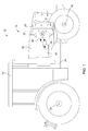
- FIG. 1 1 shows an agricultural work vehicle 12, shown only schematically in part, with a cooling system 10 arranged in a front region for the waste-heat cooling of an internal combustion engine 20 which is seated in an engine compartment 18.
- the agricultural work vehicle 12 further includes a cab 14, a front axle 16, and a rear axle 22 driven by the engine 20.
- a frame 24 serves as a structural member of the individual components of the work vehicle 12.
- the cooling system 10 For dissipating the heat developed during operation of the internal combustion engine 20, the cooling system 10 comprises a coolant flow-through heat exchanger 28 to be acted upon by an air flow and air flow generating air conveying means 32 in the form of a fan. Both the heat exchanger 28 and the fan 32 may be arranged in front of the engine 20 in the direction of travel of the work machine 12. In addition, the fan 32 may be disposed between the engine 20 and the heat exchanger 32.
- the fan 32 may be driven by a hydraulic motor 30 about an axis of rotation D, which in turn may be powered by a hydraulic pump 26 driven by the engine 20.
- the fan 32 of the hydraulic motor 30 can be driven, if necessary, both in one direction of rotation and in the opposite direction of rotation.
- the air flow generated by the fan 32 is represented by arrows which are to represent a flow direction of the air flow from the environment, through the heat exchanger 28 and into the engine compartment 18.
- the fan 32 is thus activated and driven in the direction of rotation, in which, at least when the internal combustion engine 20 is warm, an air flow effective as a cooling air flow from the environment into the engine compartment 18 is generated.
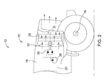
- the fan 32 is driven and driven in the opposite direction of rotation, so that an air flow is generated from the engine compartment 18, through the heat exchanger 28 and into the environment.
- this presently designated as opposite direction of rotation of the fan 32 is driven according to the invention immediately after the cold start and during the subsequent warm-up phase of the internal combustion engine 20.
- the term cold start is defined in the context of this application as a state in which a temperature level of the internal combustion engine 20, which is represented for example by the coolant temperature or the engine oil temperature, well below the operating temperature of the engine 20, the operating temperature regularly by a coolant temperature between 80 ° C and 100 ° C or an engine oil temperature between 90 ° C and 110 ° C is characterized.
- a cold start condition exists via the external temperature sensor, coolant temperature sensor and engine oil temperature sensor present on the agricultural machine 12 whether a cold start condition exists. If a cold start state, after the cold start of the engine 20, the fan 32 is driven in the opposite direction of rotation and driven, so that an air flow from the engine compartment 18, through the heat exchanger 28 and into the environment is generated. Since after a cold start of the engine 20, the exhaust manifold is hot quickly, this heats the engine compartment 18 quickly compared to the ambient temperature. This elevated temperature is used in carrying out the method according to the invention to heat the coolant located in the heat exchanger 28 before the coolant thermostat has reached its switching temperature and has released the flow through the main cooling circuit. When the internal combustion engine 20 has reached its operating temperature, the direction of rotation of the fan is reversed and driven and driven in the direction of rotation, in which an effective as a cooling air flow of air from the environment is generated in the engine compartment 18.
Landscapes
- Engineering & Computer Science (AREA)
- Chemical & Material Sciences (AREA)
- Combustion & Propulsion (AREA)
- Mechanical Engineering (AREA)
- Transportation (AREA)
- General Engineering & Computer Science (AREA)
- Cooling, Air Intake And Gas Exhaust, And Fuel Tank Arrangements In Propulsion Units (AREA)
- Air-Conditioning For Vehicles (AREA)
Abstract
Description
- Die Erfindung betrifft ein Verfahren zur Kühlung eines Kühlmittels für die Abwärmekühlung eines Verbrennungsmotors in einem landwirtschaftlichen Arbeitsfahrzeug, wobei ein von dem Kühlmittel durchflossener Wärmetauscher und Luftfördermittel zur Erzeugung eines Luftstroms durch den Wärmetauscher vorgesehen sind.
- Fluidbasierte Kühlsysteme für die Abwärmekühlung eines Verbrennungsmotors sind in der Regel derart konzipiert, dass der Kühlkreislauf über einen Kühlmittelthermostat in einer Nebenkühlkreislauf, auch Kurzschlusskreislauf genannt, und einen Hauptkühlkreis unterteilt ist. Prinzipiell befindet sich der Kühlmittelthermostat während der Warmlaufphase in eine Stellung, in der der Durchfluss des Kühlmittels durch den in dem Hauptkühlkreis befindlichen Wärmetauscher, auch Motorkühler genannt, gesperrt ist und ein Durchfluss des Kühlmittels durch eine den Wärmetauscher kurzschließende Kühlmittelleitung freigegeben ist. Die damit einhergehende Reduzierung des umgewälzten Kühlmittels führt zu einem schnelleren Durchlaufen der Warmlaufphase und Erreichen der Betriebstemperatur des Verbrennungsmotors. In den Bereich der sogenannten Schalttemperatur des Kühlmittelthermostats wird die kurzschließende Kühlmittelleitung in dem Maße verschlossen, in dem der Durchfluss durch den Wärmetauscher geöffnet wird. Hierbei wird also noch nicht erwärmtes Kühlmittels in den Kühlmittelkreislauf miteinbezogen und muss auf die höhere Temperatur erwärmt werden. Hierbei kommt es somit zu einem kurzfristig Temperaturabfall in dem Kühlmittelkreislauf. Weiterhin ist die Warmlaufphase durchaus von einer gewissen Dauer, während relativ unmittelbar nach dem Kaltstart die Temperatur in dem Motorraum, in dem der Verbrennungsmotor einsitzt, die Umgebungstemperatur übersteigt.
- Die Aufgabe der vorliegenden Erfindung besteht darin, ein Kühlsystem dahingehend zu verbessern, dass eine weiter verkürzte Warmlaufphase des Verbrennungsmotors erreicht wird.
- Die Aufgabe wird gelöst durch ein Verfahren zur kombinierten Vorerwärmung und Kühlung eines Kühlmittels für die Abwärmekühlung eines Verbrennungsmotors in einem landwirtschaftlichen Arbeitsfahrzeug, wobei ein von dem Kühlmittel durchflossener Wärmetauscher und Luftfördermittel zur Erzeugung eines Luftstroms durch den Wärmetauscher vorgesehen sind und die Luftfördermittel derart ausgelegt sind, den Luftstrom bedarfsweise in einer Richtung auf den Verbrennungsmotor zu oder in einer Richtung weg von dem Verbrennungsmotor zu erzeugen, bei dem die Luftfördermittel zur Erzeugung des Luftstroms in Richtung weg von dem Verbrennungsmotor angesteuert werden, solange ein einen Temperaturzustand des Verbrennungsmotors charakterisierender Temperaturwert einen Schwellenwert unterschreiten und die Luftfördermittel bei Überschreiten des Zustandswerts reversiert angesteuert werden.
- Das erfindungsgemäße Verfahren ist in vorteilhafterweise dazu geeignet, die Temperaturdifferenz auszunutzen, die nach einem Kaltstart des Verbrennungsmotors während der Warmlaufphase zwischen der Umgebungstemperatur und der Motorraumtemperatur entstehen kann. Da in der Regel im Moment des Kaltstarts das Kühlmittel in dem Wärmetauscher sich auf dem Niveau der Umgebungstemperatur befindet, stellt sich während der Warmlaufphase eine Temperaturdifferenz zwischen dem Kühlmittel in dem Wärmetauscher und dem Motorraum ein. Durch das erfindungsgemäße Verfahren wird zunächst erreicht, dass es bei Erreichen der Schalttemperatur des Kühlmittelthermostats, das heißt bei Öffnen des Durchflusses durch den Wärmetaucher beziehungsweise den Hauptkühlkreis, zu keinem oder zumindest zu einem reduzierten kurzfristigen Temperaturabfall in dem Kühlmittelkreislauf kommt. Weiterhin kann durch das erfindungsgemäße Verfahren erreicht werden, dass die Dauer der Warmlaufphase verkürzt wird, da ein zusätzlicher Wärmeeintrag in den Kühlmittelkreis während der Warmlaufphase stattfindet. Entscheidend ist, dass dieser Wärmeeintrag von einer Wärmequelle stammt, beispielsweise dem Abgaskrümmer, dessen abgegebene Wärme regelmäßig keinem anderen Verwendungszweck zugeführt wird. Insofern steigt der Wirkungsgrad des Verbrennungsmotors während der Warmlaufphase.
- Bevorzugt liegt der Schwellenwert in der Höhe der Betriebstemperatur des Verbrennungsmotors. Hierdurch wird sichergestellt, dass möglichst die gesamte Warmlaufphase dafür genutzt wird, den Wärmetauscher mit der bereit im Motorraum erwärmten Luft zu durchströmen.
- Bevorzugt handelt es sich bei den Luftfördermitteln um einen elektrisch oder hydraulisch angetriebenen Ventilator. Ein solcher ist einfach in einem Kühlsystem darzustellen.
- Die vorliegende Erfindung wird anhand der nachfolgenden Figuren beschrieben. Hierin zeigen
- Figur 1
- ein landwirtschaftliches Arbeitsfahrzeug mit einen Kühlsystem angesteuert nach dem Stand der Technik und
- Figur 2
- ein landwirtschaftliches Arbeitsfahrzeug (Ausschnitt) mit einen Kühlsystem angesteuert gemäß der Erfindung.
- Die
Figur 1 zeigt ein in Teilen nur schematisch dargestelltes landwirtschaftliches Arbeitsfahrzeug 12 mit einem in einem vorderen Bereich angeordneten Kühlsystem 10 zur Abwärmekühlung eines Verbrennungsmotors 20, der in einem Motorraum 18 einsitzt. Das landwirtschaftliche Arbeitsfahrzeug 12 umfasst ferner eine Kabine 14, eine Vorderachse 16 und eine durch den Verbrennungsmotor 20 angetriebene Hinterachse 22. Ein Rahmen 24 dient als tragendes Element der einzelnen Komponenten des Arbeitsfahrzeugs 12. - Zum Abführen der während des Betriebs des Verbrennungsmotors 20 entwickelten Wärme umfasst das Kühlsystem 10 einen kühlmitteldurchströmten und mit einem Luftstrom zu beaufschlagenden Wärmetauscher 28 und den Luftstrom erzeugende Luftfördermittel 32 in Form eines Ventilators. Sowohl der Wärmetauscher 28 als auch der Ventilator 32 können in Fahrtrichtung der Arbeitsmaschine 12 vor dem Verbrennungsmotor 20 angeordnet sein. Außerdem kann der Ventilator 32 zwischen dem Verbrennungsmotor 20 und dem Wärmetauscher 32 angeordnet sein.
- In dem vorliegend beschriebenen und gezeigten Ausführungsbeispiel kann der Ventilator 32 von einem Hydraulikmotor 30 um eine Drehachse D angetrieben werden, der seinerseits von einer durch den Verbrennungsmotor 20 angetriebenen Hydraulikpumpe 26 gespeist werden kann. Erfindungsgemäß ist vorgesehen ist, dass der Ventilator 32 von dem Hydraulikmotor 30 bedarfsweise sowohl in der einen Rotationrichtung als auch in der entgegengesetzten Rotationrichtung angetrieben werden kann. In der
Figur 1 ist der durch den Ventilator 32 erzeugte Luftstrom durch Pfeile dargestellt, die eine Strömungsrichtung des Luftstroms aus der Umgebung, durch den Wärmetauscher 28 hindurch und in den Motorraum 18 repräsentieren sollen. Der Ventilator 32 wird somit in der Rotationsrichtung angesteuert und angetrieben, in der, zumindest bei betriebswarmem Verbrennungsmotor 20, ein als Kühlluftstrom wirksamer Luftstrom aus der Umgebung in den Motorraum 18 erzeugt wird. - In der
Figur 2 ist der Ventilator 32 in der entgegengesetzten Rotationsrichtung angesteuert und angetrieben, so dass ein Luftstrom aus dem Motorraum 18, durch den Wärmetauscher 28 und in die Umgebung erzeugt wird. In dieser vorliegend als entgegengesetzt bezeichneten Rotationsrichtung wird der Ventilator 32 erfindungsgemäß unmittelbar nach dem Kaltstart und während der darauffolgenden Warmlaufphase des Verbrennungsmotors 20 angesteuert. Der Begriff Kaltstart wird im Kontext dieser Anmeldung als ein Zustand definiert, in dem ein Temperaturniveau des Verbrennungsmotors 20, welches beispielsweise durch die Kühlmitteltemperatur oder die Motoröltemperatur repräsentiert wird, deutlich unterhalb der Betriebstemperatur des Verbrennungsmotors 20 liegt, wobei die Betriebstemperatur regelmäßig durch eine Kühlmitteltemperatur zwischen 80°C und 100°C oder eine Motoröltemperatur zwischen 90°C und 110°C charakterisiert wird. - Für die Durchführung des erfindungsgemäßen Verfahrens wird zunächst über den auf der landwirtschaftlichen Arbeitsmaschine 12 vorhandenen Außentemperatursensor, Kühlmitteltemperatursensor und Motoröltemperatursensor detektiert, ob ein Kaltstartzustand vorliegt. Liegt ein Kaltstartzustand vor, wird nach dem erfolgten Kaltstart des Verbrennungsmotors 20 der Ventilator 32 in der entgegengesetzten Rotationsrichtung angesteuert und angetrieben, so dass ein Luftstrom aus dem Motorraum 18, durch den Wärmetauscher 28 und in die Umgebung erzeugt wird. Da nach einem Kaltstart des Verbrennungsmotors 20 der Auspuffkrümmer schnell heiß wird, heizt dieser den Motorraum 18 schnell gegenüber der Umgebungstemperatur auf. Diese erhöhte Temperatur wird bei Durchführung des erfindungsgemäßen Verfahrens genutzt, um das in dem Wärmetauscher 28 befindliche Kühlmittel zu erwärmen, bevor der Kühlmittelthermostat seine Schalttemperatur erreicht hat und den Durchfluss durch den Hauptkühlkreis freigegeben hat. Hat der Verbrennungsmotor 20 seine Betriebstemperatur erreicht, wird die Rotationsrichtung des Ventilators reversiert und in der Rotationsrichtung angesteuert und angetrieben, in der ein als Kühlluftstrom wirksamer Luftstrom aus der Umgebung in den Motorraum 18 erzeugt wird.
-
- 10
- Kühlsystem
- 12
- landwirtschaftliches Arbeitsfahrzeug
- 14
- Kabine
- 16
- Vorderachse
- 18
- Motorraum
- 20
- Verbrennungsmotor
- 22
- Hinterachse
- 24
- Rahmen
- 26
- Hydraulikpumpe
- 28
- Wärmetauscher
- 30
- Hydraulikmotor
- 32
- Ventilator
Claims (3)
- Verfahren zur kombinierten Vorerwärmung und Kühlung eines Kühlmittels für die Abwärmekühlung eines Verbrennungsmotors in einem landwirtschaftlichen Arbeitsfahrzeug,
wobei ein von dem Kühlmittel durchflossener Wärmetauscher und Luftfördermittel zur Erzeugung eines Luftstroms durch den Wärmetauscher vorgesehen sind und die Luftfördermittel derart ausgelegt sind, den Luftstrom bedarfsweise in einer Richtung auf den Verbrennungsmotor zu oder in einer Richtung weg von dem Verbrennungsmotor zu erzeugen,
bei dem die Luftfördermittel zur Erzeugung des Luftstroms in Richtung weg von dem Verbrennungsmotor angesteuert werden, solange ein einen Temperaturzustand des Verbrennungsmotors charakterisierender Temperaturwert einen Schwellenwert unterschreiten und die Luftfördermittel bei Überschreiten des Zustandswerts reversiert angesteuert werden. - Verfahren zur kombinierten Vorerwärmung und Kühlung eines Kühlmittels nach Anspruch 1, dadurch gekennzeichnet, dass der Schwellenwert in der Höhe der Betriebstemperatur des Verbrennungsmotors liegt.
- Verfahren zur kombinierten Vorerwärmung und Kühlung eines Kühlmittels nach Anspruch 1 oder 2, dadurch gekennzeichnet, dass es sich bei den Luftfördermitteln um einen elektrisch oder hydraulisch angetriebenen Ventilator handelt.
Applications Claiming Priority (1)
| Application Number | Priority Date | Filing Date | Title |
|---|---|---|---|
| DE102014220692.8A DE102014220692A1 (de) | 2014-10-13 | 2014-10-13 | Verfahren zur kombinierten Vorerwärmung und Kühlung eines Kühlmittels |
Publications (1)
| Publication Number | Publication Date |
|---|---|
| EP3009624A1 true EP3009624A1 (de) | 2016-04-20 |
Family
ID=54260636
Family Applications (1)
| Application Number | Title | Priority Date | Filing Date |
|---|---|---|---|
| EP15187895.6A Withdrawn EP3009624A1 (de) | 2014-10-13 | 2015-10-01 | Verfahren zur kombinierten vorerwärmung und kühlung eines kühlmittels |
Country Status (4)
| Country | Link |
|---|---|
| US (1) | US20160102597A1 (de) |
| EP (1) | EP3009624A1 (de) |
| CA (1) | CA2908153A1 (de) |
| DE (1) | DE102014220692A1 (de) |
Cited By (2)
| Publication number | Priority date | Publication date | Assignee | Title |
|---|---|---|---|---|
| EP3299201A1 (de) * | 2016-09-07 | 2018-03-28 | AGCO International GmbH | Fahrzeugtank |
| WO2018229705A1 (en) * | 2017-06-15 | 2018-12-20 | Baruffaldi S.P.A. | Hybrid apparatus for controlling the rotation of a fan for cooling the cooling fluid of a vehicle |
Families Citing this family (5)
| Publication number | Priority date | Publication date | Assignee | Title |
|---|---|---|---|---|
| DE102015225426A1 (de) * | 2015-12-16 | 2017-06-22 | Robert Bosch Gmbh | Lüftersystem für ein Kraftfahrzeug |
| GB2555864B (en) * | 2016-11-15 | 2020-01-08 | Perkins Engines Co Ltd | Control system for thermal management of an engine aftertreatment device |
| JP2019116198A (ja) * | 2017-12-27 | 2019-07-18 | ヤマハ発動機株式会社 | 車両 |
| US12404799B1 (en) | 2024-08-09 | 2025-09-02 | Deere & Company | Cooling system for a work vehicle |
| DE102024129868B3 (de) | 2024-10-15 | 2026-01-15 | Audi Aktiengesellschaft | Verfahren zum Betreiben eines Kühlerpakets für ein Kraftfahrzeug, Steuereinrichtung zum Durchführen eines Verfahrens sowie Kraftfahrzeug mit Kühlerpaket und Steuereinrichtung |
Citations (4)
| Publication number | Priority date | Publication date | Assignee | Title |
|---|---|---|---|---|
| EP0293334A1 (de) * | 1987-04-28 | 1988-11-30 | FIAT AUTO S.p.A. | Verfahren und Vorrichtung zur Erhöhung der Kühlung der Kühlflüssigkeit eines Verbrennungsmotors für ein Kraftfahrzeug |
| US6076488A (en) * | 1997-03-17 | 2000-06-20 | Shin Caterpillar Mitsubishi Ltd. | Cooling device for a construction machine |
| US20020029912A1 (en) * | 2000-05-09 | 2002-03-14 | Mackelvie Winston | Bi-directional automotive cooling fan |
| US20120304944A1 (en) * | 2011-05-31 | 2012-12-06 | Nelson Bryan E | Engine system with reversible fan |
Family Cites Families (9)
| Publication number | Priority date | Publication date | Assignee | Title |
|---|---|---|---|---|
| US2734493A (en) * | 1956-02-14 | Variable and reversible pitch fan for | ||
| US2517932A (en) * | 1948-06-11 | 1950-08-08 | Evans Prod Co | Fluid pressure variable pitch fan control |
| US3106343A (en) * | 1960-06-23 | 1963-10-08 | Joseph R Holland | Means for controlling the temperature of an internal combustion engine |
| US6859671B1 (en) * | 1995-05-30 | 2005-02-22 | Roy-G-Biv Corporation | Application programs for motion control devices including access limitations |
| US7121368B2 (en) * | 2000-05-09 | 2006-10-17 | Mackelvie Winston | Bi-directional automotive cooling fan |
| PL2578888T3 (pl) * | 2011-10-07 | 2019-05-31 | Voegele Ag J | Maszyna budowlana z automatyczną regulacją prędkości obrotowej wentylatora |
| US8960349B2 (en) * | 2013-04-16 | 2015-02-24 | Deere & Company | Hydraulic fluid warm-up using hydraulic fan reversal |
| US9586473B2 (en) * | 2013-07-15 | 2017-03-07 | Deere & Company | Vehicle with selectively reversible cooling fan |
| US20150021925A1 (en) * | 2014-10-09 | 2015-01-22 | Caterpillar Inc. | Method to control temperature of engine of generator system |
-
2014
- 2014-10-13 DE DE102014220692.8A patent/DE102014220692A1/de active Pending
-
2015
- 2015-10-01 EP EP15187895.6A patent/EP3009624A1/de not_active Withdrawn
- 2015-10-09 CA CA2908153A patent/CA2908153A1/en not_active Abandoned
- 2015-10-12 US US14/880,343 patent/US20160102597A1/en not_active Abandoned
Patent Citations (4)
| Publication number | Priority date | Publication date | Assignee | Title |
|---|---|---|---|---|
| EP0293334A1 (de) * | 1987-04-28 | 1988-11-30 | FIAT AUTO S.p.A. | Verfahren und Vorrichtung zur Erhöhung der Kühlung der Kühlflüssigkeit eines Verbrennungsmotors für ein Kraftfahrzeug |
| US6076488A (en) * | 1997-03-17 | 2000-06-20 | Shin Caterpillar Mitsubishi Ltd. | Cooling device for a construction machine |
| US20020029912A1 (en) * | 2000-05-09 | 2002-03-14 | Mackelvie Winston | Bi-directional automotive cooling fan |
| US20120304944A1 (en) * | 2011-05-31 | 2012-12-06 | Nelson Bryan E | Engine system with reversible fan |
Cited By (5)
| Publication number | Priority date | Publication date | Assignee | Title |
|---|---|---|---|---|
| EP3299201A1 (de) * | 2016-09-07 | 2018-03-28 | AGCO International GmbH | Fahrzeugtank |
| US10144277B2 (en) | 2016-09-07 | 2018-12-04 | Agco International Gmbh | Vehicle tank |
| WO2018229705A1 (en) * | 2017-06-15 | 2018-12-20 | Baruffaldi S.P.A. | Hybrid apparatus for controlling the rotation of a fan for cooling the cooling fluid of a vehicle |
| CN110741174A (zh) * | 2017-06-15 | 2020-01-31 | 巴鲁法蒂股份公司 | 控制用于冷却车辆的冷却流体的风扇旋转的混合设备 |
| CN110741174B (zh) * | 2017-06-15 | 2021-03-05 | 巴鲁法蒂股份公司 | 控制用于冷却车辆的冷却流体的风扇旋转的混合设备 |
Also Published As
| Publication number | Publication date |
|---|---|
| US20160102597A1 (en) | 2016-04-14 |
| DE102014220692A1 (de) | 2016-04-14 |
| CA2908153A1 (en) | 2016-04-13 |
Similar Documents
| Publication | Publication Date | Title |
|---|---|---|
| DE102014220692A1 (de) | Verfahren zur kombinierten Vorerwärmung und Kühlung eines Kühlmittels | |
| DE102014215074B4 (de) | Temperieranordnung für Getriebeöl eines Kraftfahrzeugs sowie Verfahren zum Temperieren von Getriebeöl eines Kraftfahrzeugs | |
| DE102016115631A1 (de) | Verbrennungsmotorsystem mit kühlmittelsteuerventil | |
| DE102014116350A1 (de) | Klimakreislauf für ein Hybridkraftfahrzeug sowie Verfahren zum Vorheizen einer Kraftfahrzeugbatterie eines Hybridkraftfahrzeugs | |
| EP2903076A1 (de) | Fahrzeugkühlkreislauf | |
| DE102012019459A1 (de) | Temperiervorrichtung eines Fahrzeugs und Verfahren zu deren Betrieb | |
| DE112009000588T5 (de) | Thermisches Management für einen verbesserten Motorbetrieb | |
| WO2019166137A1 (de) | Antrieb mit integriertem orc | |
| EP2924259B1 (de) | Antriebssystem | |
| DE112014004116T5 (de) | Vorrichtung zur Steuerung der Menge eines Luftstroms für ein Kraftfahrzeug | |
| DE102013224125A1 (de) | System zur Rückgewinnung von Abgaswärme | |
| EP2149688B1 (de) | Kühlanordnung eines Kraftfahrzeuges | |
| DE102016218764A1 (de) | Brennkraftmaschine eines Kraftfahrzeugs mit einer Abwärmenutzungseinrichtung | |
| DE102012210456A1 (de) | Abgassystem für den Verbrennungsmotor eines Fahrzeugs | |
| DE102015223044B4 (de) | Hilfskühlsystem für ein mit einem turbolader versehenesfahrzeug | |
| WO2019091949A1 (de) | Antriebseinrichtung mit einem kühlmittelkreislauf für ein kraftfahrzeug | |
| DE102013114769A1 (de) | Integrierte abwärmerückgewinnung | |
| DE102014208545A1 (de) | Vorrichtung zur Kühlung von Ladeluft | |
| EP1536961B1 (de) | System und verfahren zur regulierung des wärmehaushalts eines fahrzeugs | |
| DE60125295T2 (de) | Kühlsystem für eine Brennkraftmaschine | |
| EP2108813A1 (de) | Vorrichtung zum Kühlen oder Erwärmen eines Verbrennungsmotors | |
| EP3135879B1 (de) | Bypass-einrichtung zur reduzierung einer rezirkulation erwärmter luft in eine kühleinrichtung | |
| EP3527800A1 (de) | Kühlkreislauf für eine antriebseinheit eines kraftfahrzeuges | |
| DE102013113229A1 (de) | Kälteanlage für ein Kraftfahrzeug mit Mittel- oder Heckmotor sowie Verfahren zur Klimatisierung eines Kraftfahrzeugs mit Mittel- oder Heckmotor | |
| DE102018205130A1 (de) | Verfahren zum Erwärmen eines Antriebs eines Hybridfahrzeugs sowie Vorwärmeinrichtung |
Legal Events
| Date | Code | Title | Description |
|---|---|---|---|
| PUAI | Public reference made under article 153(3) epc to a published international application that has entered the european phase |
Free format text: ORIGINAL CODE: 0009012 |
|
| AK | Designated contracting states |
Kind code of ref document: A1 Designated state(s): AL AT BE BG CH CY CZ DE DK EE ES FI FR GB GR HR HU IE IS IT LI LT LU LV MC MK MT NL NO PL PT RO RS SE SI SK SM TR |
|
| AX | Request for extension of the european patent |
Extension state: BA ME |
|
| 17P | Request for examination filed |
Effective date: 20161020 |
|
| RBV | Designated contracting states (corrected) |
Designated state(s): AL AT BE BG CH CY CZ DE DK EE ES FI FR GB GR HR HU IE IS IT LI LT LU LV MC MK MT NL NO PL PT RO RS SE SI SK SM TR |
|
| STAA | Information on the status of an ep patent application or granted ep patent |
Free format text: STATUS: THE APPLICATION IS DEEMED TO BE WITHDRAWN |
|
| 18D | Application deemed to be withdrawn |
Effective date: 20161021 |