EP3009277A1 - Pneumatic tire - Google Patents
Pneumatic tire Download PDFInfo
- Publication number
- EP3009277A1 EP3009277A1 EP14811548.8A EP14811548A EP3009277A1 EP 3009277 A1 EP3009277 A1 EP 3009277A1 EP 14811548 A EP14811548 A EP 14811548A EP 3009277 A1 EP3009277 A1 EP 3009277A1
- Authority
- EP
- European Patent Office
- Prior art keywords
- step portion
- block
- height
- groove bottom
- pneumatic tire
- Prior art date
- Legal status (The legal status is an assumption and is not a legal conclusion. Google has not performed a legal analysis and makes no representation as to the accuracy of the status listed.)
- Granted
Links
Images



Classifications
-
- B—PERFORMING OPERATIONS; TRANSPORTING
- B60—VEHICLES IN GENERAL
- B60C—VEHICLE TYRES; TYRE INFLATION; TYRE CHANGING; CONNECTING VALVES TO INFLATABLE ELASTIC BODIES IN GENERAL; DEVICES OR ARRANGEMENTS RELATED TO TYRES
- B60C11/00—Tyre tread bands; Tread patterns; Anti-skid inserts
- B60C11/03—Tread patterns
- B60C11/0306—Patterns comprising block rows or discontinuous ribs
- B60C11/0309—Patterns comprising block rows or discontinuous ribs further characterised by the groove cross-section
-
- B—PERFORMING OPERATIONS; TRANSPORTING
- B60—VEHICLES IN GENERAL
- B60C—VEHICLE TYRES; TYRE INFLATION; TYRE CHANGING; CONNECTING VALVES TO INFLATABLE ELASTIC BODIES IN GENERAL; DEVICES OR ARRANGEMENTS RELATED TO TYRES
- B60C11/00—Tyre tread bands; Tread patterns; Anti-skid inserts
- B60C11/03—Tread patterns
- B60C11/11—Tread patterns in which the raised area of the pattern consists only of isolated elements, e.g. blocks
-
- B—PERFORMING OPERATIONS; TRANSPORTING
- B60—VEHICLES IN GENERAL
- B60C—VEHICLE TYRES; TYRE INFLATION; TYRE CHANGING; CONNECTING VALVES TO INFLATABLE ELASTIC BODIES IN GENERAL; DEVICES OR ARRANGEMENTS RELATED TO TYRES
- B60C11/00—Tyre tread bands; Tread patterns; Anti-skid inserts
- B60C11/03—Tread patterns
- B60C11/0327—Tread patterns characterised by special properties of the tread pattern
-
- B—PERFORMING OPERATIONS; TRANSPORTING
- B60—VEHICLES IN GENERAL
- B60C—VEHICLE TYRES; TYRE INFLATION; TYRE CHANGING; CONNECTING VALVES TO INFLATABLE ELASTIC BODIES IN GENERAL; DEVICES OR ARRANGEMENTS RELATED TO TYRES
- B60C11/00—Tyre tread bands; Tread patterns; Anti-skid inserts
- B60C11/03—Tread patterns
- B60C11/13—Tread patterns characterised by the groove cross-section, e.g. for buttressing or preventing stone-trapping
- B60C11/1307—Tread patterns characterised by the groove cross-section, e.g. for buttressing or preventing stone-trapping with special features of the groove walls
-
- B—PERFORMING OPERATIONS; TRANSPORTING
- B60—VEHICLES IN GENERAL
- B60C—VEHICLE TYRES; TYRE INFLATION; TYRE CHANGING; CONNECTING VALVES TO INFLATABLE ELASTIC BODIES IN GENERAL; DEVICES OR ARRANGEMENTS RELATED TO TYRES
- B60C11/00—Tyre tread bands; Tread patterns; Anti-skid inserts
- B60C11/03—Tread patterns
- B60C11/13—Tread patterns characterised by the groove cross-section, e.g. for buttressing or preventing stone-trapping
- B60C11/1376—Three dimensional block surfaces departing from the enveloping tread contour
-
- B—PERFORMING OPERATIONS; TRANSPORTING
- B60—VEHICLES IN GENERAL
- B60C—VEHICLE TYRES; TYRE INFLATION; TYRE CHANGING; CONNECTING VALVES TO INFLATABLE ELASTIC BODIES IN GENERAL; DEVICES OR ARRANGEMENTS RELATED TO TYRES
- B60C11/00—Tyre tread bands; Tread patterns; Anti-skid inserts
- B60C11/03—Tread patterns
- B60C11/13—Tread patterns characterised by the groove cross-section, e.g. for buttressing or preventing stone-trapping
- B60C11/1376—Three dimensional block surfaces departing from the enveloping tread contour
- B60C11/1392—Three dimensional block surfaces departing from the enveloping tread contour with chamfered block edges
-
- B—PERFORMING OPERATIONS; TRANSPORTING
- B60—VEHICLES IN GENERAL
- B60C—VEHICLE TYRES; TYRE INFLATION; TYRE CHANGING; CONNECTING VALVES TO INFLATABLE ELASTIC BODIES IN GENERAL; DEVICES OR ARRANGEMENTS RELATED TO TYRES
- B60C11/00—Tyre tread bands; Tread patterns; Anti-skid inserts
- B60C11/03—Tread patterns
- B60C11/0327—Tread patterns characterised by special properties of the tread pattern
- B60C2011/0334—Stiffness
-
- B—PERFORMING OPERATIONS; TRANSPORTING
- B60—VEHICLES IN GENERAL
- B60C—VEHICLE TYRES; TYRE INFLATION; TYRE CHANGING; CONNECTING VALVES TO INFLATABLE ELASTIC BODIES IN GENERAL; DEVICES OR ARRANGEMENTS RELATED TO TYRES
- B60C11/00—Tyre tread bands; Tread patterns; Anti-skid inserts
- B60C11/03—Tread patterns
- B60C2011/0337—Tread patterns characterised by particular design features of the pattern
- B60C2011/0339—Grooves
- B60C2011/0341—Circumferential grooves
-
- B—PERFORMING OPERATIONS; TRANSPORTING
- B60—VEHICLES IN GENERAL
- B60C—VEHICLE TYRES; TYRE INFLATION; TYRE CHANGING; CONNECTING VALVES TO INFLATABLE ELASTIC BODIES IN GENERAL; DEVICES OR ARRANGEMENTS RELATED TO TYRES
- B60C11/00—Tyre tread bands; Tread patterns; Anti-skid inserts
- B60C11/03—Tread patterns
- B60C11/12—Tread patterns characterised by the use of narrow slits or incisions, e.g. sipes
- B60C11/1204—Tread patterns characterised by the use of narrow slits or incisions, e.g. sipes with special shape of the sipe
- B60C2011/1213—Tread patterns characterised by the use of narrow slits or incisions, e.g. sipes with special shape of the sipe sinusoidal or zigzag at the tread surface
Definitions
- the present invention relates to a pneumatic tire, and in particular to a pneumatic tire that takes into consideration travel over snow.
- JP-A No. 2006-137230 describes a pneumatic tire provided with a block that generates torque about a direction normal to a road surface when compressed (see Patent Document 1).
- this block the angle of a groove wall at a kick-out end gradually increases on progression toward the tire width direction outside, the angle of a groove wall at a dig-in end gradually decreases on progression toward the width direction outside, and the angle of a groove wall on a tire circumferential direction groove side gradually decreases on progression along the rotation direction.
- a front face of the block is accordingly disposed with a twisted structure with respect to bottom faces of the grooves.
- an object of the present invention is to enable heel-and-toe wear to be suppressed while securing snow performance.
- a pneumatic tire according to a first aspect of the present invention is configured for use on snowy roads, and includes: a block that is provided at a tread, and that is demarcated by mutually intersecting main grooves respectively extending around a tire circumferential direction and along a tire width direction; a first step portion that extends along a side wall portion at one tire circumferential direction side of the block, and that has a height from a groove bottom of the main groove where the one side wall portion is present, which is lower than a tread face and higher than the groove bottom; and a second step portion that extends along a side wall portion at another tire circumferential direction side of the block, that has a height from a groove bottom of the main groove where the other side wall portion is present, which is lower than the tread face and higher than the groove bottom, and that has a smaller width than the first step portion.
- the first step portion is provided at the one tire circumferential direction side wall portion of the block of the tread, and the second step portion is provided at the other side wall portion.
- the first step portion and the second step portion are set a level lower than the tread face, thereby securing a greater volume for the main grooves and increasing the shear force from snow columns in the main grooves, thereby enabling snow performance to be secured.
- the width of the second step portion is set smaller than the width of the first step portion, securing the rigidity of the second step portion side of the block. Accordingly, when traction or braking force acts on the tire, deformation of the second step portion side of the block is suppressed even when the block is dragged against the road surface. This thereby suppresses heel-and-toe wear.
- a second aspect of the present invention is the pneumatic tire of the first aspect, wherein the height of the second step portion from the groove bottom is greater than or equal to the height of the first step portion.
- the height of the second step portion is greater than or equal to the height of the first step portion.
- the rigidity of the second step portion side of the block is secured at, or greater than, that of the first step portion side. Accordingly, when traction or braking force acts on the tire, deformation of the second step portion side of the block is suppressed even when the block is dragged against the road surface. This thereby suppresses heel-and-toe wear.
- a third aspect of the present invention is the pneumatic tire of either the first aspect or the second aspect, wherein: the first step portion is provided on a dig-in side of the block; and the second step portion is provided on a kick-out side of the block.
- the dig-in side is the side of the block that contacts the road surface first when the tire rotates in a specific direction
- the kick-out side is the side of the block that is last to make contact (the side that is last to leave the road surface).
- the first step portion is provided on the dig-in side of the block, and the second step portion that has a narrower width than the first step portion is provided on the kick-out side of the block. Accordingly, the kick-out side of the block has higher rigidity than the dig-in side. Accordingly, when traction acts on the tire, deformation of the kick-out side of the block is suppressed, enabling heel-and-toe wear to be suppressed.
- a fourth aspect of the present invention is the pneumatic tire of any one of the first aspect to the third aspect, wherein: the block includes an acute angle portion at a position on the second step portion side of the block where an acute angle of intersection is formed between the main grooves; and the width of the second step portion is such that one end positioned on the acute angle portion side is smaller than another end positioned on an opposite side from the acute angle portion side.
- the acute angle portion is provided at a position on the second step portion side of the block, and the width of the one end of the second step portion positioned on the acute angle portion side is set smaller than the width of the other end positioned on the opposite side from the acute angle portion, thereby securing the rigidity of the acute angle portion. Accordingly, when traction or braking force acts on the tire, deformation of the acute angle portion of the block is suppressed even when the block is dragged against the road surface. This thereby enables heel-and-toe wear to be suppressed even when the block includes the acute angle portion.
- a fifth aspect of the present invention is the pneumatic tire of the fourth aspect, wherein the width of the second step portion gradually decreases on progression from the other end toward the one end.
- the width of the second step portion gradually decreases on progression from the one end toward the other end, thereby enabling a gentle change in the block rigidity along the second step portion.
- a sixth aspect of the present invention is the pneumatic tire of either the fourth aspect or the fifth aspect, wherein the height of the second step portion from the groove bottom is higher at the one end than at the other end.
- the height of the second step portion from the groove bottom of the main groove is set greater at the one end than at the other end, thereby further securing the rigidity of the acute angle portion. Accordingly, when traction or braking force acts on the tire, deformation of the acute angle portion of the block is further suppressed. This thereby enables heel-and-toe wear to be further suppressed at the block provided with the acute angle portion on the second step portion side.
- a seventh aspect of the present invention is the pneumatic tire of the sixth aspect, wherein the height of the second step portion from the groove bottom gradually increases on progression from the other end toward the one end.
- the height of the second step portion gradually increases on progression from the other end toward the one end, thereby enabling a gentle change in the block rigidity along the second step portion.
- An eighth aspect of the present invention is the pneumatic tire of any one of the first aspect to the seventh aspect, wherein the height of the second step portion from the groove bottom is from 50% to 80% of the height from the groove bottom to the tread face.
- the lower limit is set at 50% since below this value, the block rigidity becomes difficult to secure
- the upper limit is set at 80% since above this value, the increase in the volume of the main grooves becomes small.
- the height of the second step portion from the groove bottom is from 50% to 80% of a height from the groove bottom to the tread face, thereby enabling heel-and-toe wear to be even further suppressed, while improving snow performance.
- a ninth aspect of the present invention is the pneumatic tire of any one of the first aspect to the eighth aspect, wherein the main groove extending around the tire circumferential direction is inclined with respect to the tire circumferential direction, and the pneumatic tire further includes: a third step portion that extends along a side wall portion at one tire width direction side of the block, and that has a height from a groove bottom of the main groove where the one side wall portion is present, which is lower than the tread face and higher than the groove bottom; and a fourth step portion that extends along a side wall portion at another tire width direction side of the block, that has a height from a groove bottom of the main groove where the other side wall portion is present, which is lower than the tread face and higher than the groove bottom, and that has a smaller width than the third step portion.
- the third step portion and the fourth step portion are provided at the side wall portions on both tire width direction sides of the block, and the rigidity of the block is secured on the fourth step portion side. This thereby enables heel-and-toe wear to be suppressed, even when a tire width direction component arises in the block due to force received from the road surface when travelling.
- a tenth aspect of the present invention is the pneumatic tire of the ninth aspect, wherein: an acute angle portion is provided at a position on the fourth step portion side of the block where an acute angle of intersection is formed between the main grooves; and the width of the fourth step portion is such that one end positioned on the acute angle portion side is smaller than another end positioned on an opposite side from the acute angle portion side.
- the acute angle portion is provided at a position on the fourth step portion side of the block, and the width of the one end of the fourth step portion on the acute angle portion side is set smaller than the width of the other end on the opposite side from the acute angle portion, thereby securing the rigidity of the acute angle portion. Accordingly, when traction or braking force acts on the tire, deformation of the acute angle portion of the block is suppressed even when the block is dragged against the road surface. This thereby enables heel-and-toe wear to be suppressed even when the block includes the acute angle portion on the fourth step portion side.
- An eleventh aspect of the present invention is the pneumatic tire of the tenth aspect, wherein the width of the fourth step portion gradually decreases on progression from the other end toward the one end.
- the width of the fourth step portion gradually decreases on progression from the one end toward the other end, thereby enabling a gentle change in the block rigidity along the fourth step portion.
- a twelfth aspect of the present invention is the pneumatic tire of either the tenth aspect or the eleventh aspect, wherein the height of the fourth step portion from the groove bottom is higher at the one end than at the other end.
- the height of the fourth step portion from the groove bottom of the main groove is set greater at the one end than at the other end, thereby further securing the rigidity of the acute angle portion. Accordingly, when traction or braking force acts on the tire, deformation of the acute angle portion of the block is further suppressed. This thereby enables heel-and-toe wear to be even further suppressed in the block provided with the acute angle portion on the fourth step portion side.
- a thirteenth aspect of the present invention is the pneumatic tire of the twelfth aspect, wherein the height of the fourth step portion from the groove bottom gradually increases on progression from the other end toward the one end.
- the height of the fourth step portion gradually increases on progression from the other end toward the one end, thereby enabling a gentle change in the block rigidity along the fourth step portion.
- the pneumatic tire according to the present invention obtains the excellent advantageous effects of enabling heel-and-toe wear to be suppressed, while securing snow performance.
- Fig. 1 illustrates a pneumatic tire 10 according to the present exemplary embodiment, this being a snow tire including blocks 14, a first step portion 11 extending along each block 14, and a second step portion 12 extending along each block 14.
- plural of the blocks 14 are provided at a tread 16, only one of the blocks 14 is illustrated in the drawings.
- the first step portion 11 and the second step portion 12 are configured integrally to the block 14.
- the blocks 14 are provided at the tread 16, and are demarcated by mutually intersecting main grooves that respectively extend around the tire circumferential direction and along the tire width direction.
- the main grooves are, for example, configured by circumferential direction main grooves 22, and lateral main grooves 24.
- the circumferential direction main grooves 22 extend parallel to the tire circumferential direction
- the lateral main grooves 24 extend parallel to the tire width direction.
- Each block 14 accordingly has a substantially rectangular shape in plan view.
- the first step portion 11 extends along a side wall portion 14F at one tire circumferential direction side of the block 14, for example on the dig-in side in a tire rotation direction R.
- a height H1 of the first step portion 11 from a groove bottom 24A of the lateral main groove 24 on the side wall portion 14F on the dig-in side is set lower than a tread face 14A, and higher than the groove bottom 24A.
- H1 ⁇ H when H is a height of the tread face 14A of the block 14 from the groove bottom 24A.
- the dig-in side refers to the side of the block 14 that contacts the road surface first in the tire rotation direction R.
- the second step portion 12 extends along a side wall portion 14R at another tire circumferential direction side of the block 14, for example on the kick-out side.
- a height H2 of the second step portion 12 from the groove bottom 24A of the lateral main groove 24 where the side wall portion 14R on the kick-out side is present is set lower than the tread face 14A, and higher than the groove bottom 24A. Namely, in Fig. 1B , H2 ⁇ H.
- the kick-out side refers to the side of the block 14 that is last to make contact (the side that is last to leave the road surface) in the tire rotation direction R.
- the height H1 of the first step portion 11 from the groove bottom 24A and the height H2 of the second step portion 12 from the groove bottom 24A are both from 50% to 80% of the height H from the groove bottom 24A to the tread face 14A.
- the lower limit is set at 50% since below this value, the block rigidity becomes difficult to secure, and the upper limit is set at 80% since above this value, the increase in the volume of the lateral main grooves 24 becomes small.
- the height H2 of the second step portion 12 from the groove bottom 24A is greater than or equal to the height H1 of the first step portion 11, and the rigidity on the second step portion 12 side of the block 14 is secured at that of the first step portion 11 side or greater.
- the relationship in size between the heights H1, H2 is more preferably H2 > H1. This thereby enables greater rigidity to be secured on the kick-out side of the block 14.
- the second step portion 12 has a smaller width than the first step portion 11. More specifically, in Fig. 1A , W2 ⁇ W1 when the width of the second step portion 12 is denoted W2, and the width of the first step portion 11 is denoted W1. Note that the widths W1, W2 respectively refer to the width in the tire circumferential direction in the cases of the first step portion 11 and the second step portion 12 that extend along the lateral main grooves 24.
- the pneumatic tire 10 according to the present exemplary embodiment is provided with the first step portion 11 and the second step portion 12 on each block 14 of the tread 16, and the first step portion 11 and the second step portion 12 are both set at a level lower than the tread face 14A.
- the width W1 of the first step portion 11 is set larger than the width W2 of the second step portion 12. This secures a greater volume for the lateral main grooves 24, and increases the shear force from snow columns in the lateral main grooves 24, thereby enabling snow performance to be secured.
- the width W2 of the second step portion 12 is set smaller than the width W1 of the first step portion 11, and the rigidity of the second step portion 12 side (kick-out side) of the block 14 is higher than that of the first step portion 11 side (dig-in side). Accordingly, when traction or braking force acts on the pneumatic tire 10, deformation of the second step portion 12 side (kick-out side) of the block 14 is suppressed even when the block 14 is dragged against the road surface. This thereby suppresses heel-and-toe wear of the pneumatic tire 10.
- the height H2 of the second step portion 12 from the groove bottom 24A is set at from 50% to 80% of the height H from the groove bottom 24A to the tread face, thereby enabling heel-and-toe wear to be more effectively suppressed, while improving snow performance.
- the lateral main grooves 24 are inclined with respect to the tire width direction.
- the block 14 accordingly has a substantially parallelogram shape in plan view, and an acute angle portion 14E is provided at a position on the second step portion 12 side of the block 14 where an angle of intersection ⁇ 1 between the circumferential direction main groove 22 and the lateral main groove 24 on the kick-out side is an acute angle.
- Widths W21, W22 of the second step portion 12 are such that one end 12A positioned on the acute angle portion 14E side is smaller than the other end 12B positioned on an opposite side from the acute angle portion 14E side.
- the widths W21, W22 of the second step portion 12 are smaller than the (uniform) width W1 of the first step portion 11, such that W21 ⁇ W22 ⁇ W1 when compared against the width W1.
- the width of the second step portion 12 gradually decreases on progression from the other end 12B (width W22) toward the one end 12A (width W21). As an example, this change in width is linear; however it may also be on a curve.
- the height of the second step portion 12 from the groove bottom 24A of the lateral main groove 24 where the side wall portion 14R on the kick-out side is present is higher at the one end 12A than at the other end 12B.
- H21 > H22 when the height of the one end 12A is denoted H21
- H22 the height of the other end 12B is denoted H22.
- Including the height H1 of the first step portion 11 illustrated in Fig. 2C preferably H21 > H22 > H1.
- the height of the second step portion 12 gradually increases on progression from the other end 12B toward the one end 12A. As an example, this change in height is linear; however it may also be on a curve.
- the height H1 of the first step portion 11 is uniform.
- the block 14 includes the acute angle portion 14E.
- the width W21 of the one end 12A positioned on the acute angle portion 14E side of the second step portion 12 is set smaller than the width W22 of the other end 12B positioned on the opposite side from the acute angle portion 14E. This accordingly secures the rigidity of the acute angle portion 14E.
- the width of the second step portion 12 gradually decreases on progression from the other end 12B toward the one end 12A, giving a gentle change in the block rigidity along the second step portion 12. Specifically, there are no sudden changes in block rigidity in the range of the second step portion 12.
- the height of the second step portion 12 from the groove bottom 24A of the main groove is set such that the height H21 of the one end 12A is higher than the height H22 of the other end 12B, further securing the rigidity of the acute angle portion 14E.
- the height of the second step portion 12 gradually increases on progression from the other end 12B toward the one end 12A, giving a gentle change in the block rigidity along the second step portion 12.
- the lateral main grooves 24 are inclined with respect to the tire width direction, and the main grooves extending in the tire circumferential direction, namely the circumferential direction main grooves 22, are inclined with respect to the tire circumferential direction.
- the block 14 is provided with an acute angle portion 14G at a position on a fourth step portion 34 side where an angle of intersection ⁇ 2 between the circumferential direction main groove 22 and the lateral main groove 24 is an acute angle.
- Respective tire width direction components arise at both tire width direction sides of the block 14 due to force received from the road surface when travelling.
- a third step portion 33 and the fourth step portion 34 are provided in addition to the first step portion 11 and the second step portion 12 of the second exemplary embodiment.
- the third step portion 33 extends along a wall portion 14S at one tire width direction side of the block 14. Heights H31, H32 from a groove bottom 22A of the circumferential direction main groove 22 where the one side wall portion 14S is present, which are lower than the tread face 14A and higher than the groove bottom 22A. Namely, in Fig. 3C and Fig. 3D , H31 ⁇ H, and H32 ⁇ H.
- the height H31 is the height of one end positioned on the acute angle portion 14E side of the third step portion 33
- the height H32 is the height of the other end 33B positioned on the opposite side from the acute angle portion 14E.
- the height H31 is higher than the height H32, namely, H31 > H32.
- the fourth step portion 34 extends along a side wall portion 14L at another tire width direction side of the block 14. Heights H41, H42 from the groove bottom 22A of the circumferential direction main groove 22 where the other side wall portion 14L is present, which are lower than the tread face 14A and higher than the groove bottom 22A. Namely, in Fig. 3C and Fig. 3E , H41 ⁇ H, and H42 ⁇ H.
- the height H41 is the height of one end 34A positioned on the acute angle portion 14G side of the fourth step portion 34
- the height H42 is the height of the other end 34B positioned on an opposite side from the acute angle portion 14G side.
- the height of the fourth step portion 34 from the groove bottom 22A is higher at the one end 34A than at the other end 34B. Namely, H41 > H42.
- the height of the fourth step portion 34 from the groove bottom 22A gradually increases on progression from the other end 34B toward the one end 34A, giving a gentle change in the block rigidity along the fourth step portion 34. As an example, this change in height is linear; however it may also be on a curve.
- the widths W41, W42 of the fourth step portion 34 are set smaller than the width W3 of the third step portion 33. Namely, W42 ⁇ W3, and W41 ⁇ W3. Specifically, in Fig. 3A and Fig. 3E , W41 ⁇ W42 when the width of the one end 34A of the fourth step portion 34 is denoted W41, and the width of the other end 34B is denoted W42. Since the widths W41, W42 of the fourth step portion 34 are smaller than the (uniform) width W3 of the third step portion 33, when the width W3 is included, W41 ⁇ W42 ⁇ W3. The width of the fourth step portion 34 gradually decreases on progression from the other end 34B toward the one end 34A. As an example, this change in width is linear; however it may also be on a curve. In the cases of the third step portion 33 and the fourth step portion 34 extending along the circumferential direction main grooves 22, the respective widths refer to the widths in the tire width direction.
- the width W3 of the third step portion 33 may be equal to the width W1 of the first step portion 11 as illustrated in Fig. 3A , or may be different to the width W1.
- the height of the first step portion 11 from the groove bottom 24A is higher at one end 11A than at the other end 11B.
- the height H32 of the other end 33B of the third step portion 33 illustrated in Fig. 3D is preferably higher than the height H12 of the other end 11B of the first step portion 11.
- the heights H31, H32 of the third step portion 33, and the heights H41, H42 of the fourth step portion 34, from the groove bottom 22A, are each from 50% to 80% of the height H from the groove bottom 22A to the tread face 14A. Note that the lower limit is set at 50% since below this value, block rigidity becomes difficult to secure, and the upper limit is set at 80% since above this value, the increase in the volume of the circumferential direction main grooves 22 becomes small.
- the one end 11A of the first step portion 11 is connected to the one end 34A of the fourth step portion 34, and the other end 11B is connected to the other end 33B of the third step portion 33.
- the one end 12A of the second step portion 12 is connected to one end 33A of the third step portion 33, and the other end 12B is connected to the other end 34B of the fourth step portion 34.
- the block 14 of the tread 16 is provided not only with the first step portion 11 and the second step portion 12, but also with the third step portion 33 and the fourth step portion 34. This accordingly secures a greater volume for the circumferential direction main grooves 22 and the lateral main grooves 24, and increases the shear force from snow columns in the circumferential direction main grooves 22 and the lateral main grooves 24, thereby enabling snow performance to be secured.
- the third step portion 33 and the fourth step portion 34 are provided at the side wall portions 14S, 14L on both tire width direction sides of the block 14, and the rigidity of the block 14 is secured on the fourth step portion 34 side.
- the block 14 includes the acute angle portions 14E, 14G.
- the rigidity of the acute angle portion 14E is secured by the second step portion 12, and the rigidity of the acute angle portion 14G is secured by the fourth step portion 34.
- the width of the fourth step portion 34 gradually decreases on progression from the other end 12B toward the one end 12A, giving a gentle change in the block rigidity along the fourth step portion 34. Specifically, there are no sudden changes in block rigidity in the range of the fourth step portion 34.
- the height of the fourth step portion 34 gradually increases on progression from the other end 34B toward the one end 34A, giving a gentle change in the block rigidity along the fourth step portion 34.
- a more specific configuration of the block 14 of the second exemplary embodiment is illustrated in Fig. 4 and Figs. 5 .
- the block 14 is provided with plural sipes 26.
- the tread 16 is configured including foam rubber.
- the sipes 26 are narrow grooves that open up when not in contact with the ground, and that close when in contact with the ground.
- the sipes 26 extend in the tire width direction, for example, and are locally formed with zigzag shapes.
- each block 14 is provided with longitudinal sipes 28 and a narrow groove 32 in order to balance the rigidity of respective portions of the block 14.
- the longitudinal sipes 28 extend around the tire circumferential direction, and cross the plural sipes 26.
- the narrow groove 32 is shallower than the circumferential direction main grooves 22 and the lateral main grooves 24, and crosses the block 14 to open onto the first step portion 11 and the second step portion 12 respectively.
- the narrow groove 32 includes an inclined portion 32A that is inclined with respect to the tire circumferential direction, and a straight portion 32B that extends in the tire circumferential direction.
- the groove bottom of the narrow groove 32 is, for example, at a higher position than the first step portion 11 and the second step portion 12. This is so as to secure handling stability performance on dry road surfaces.
- the one end 12A of the second step portion 12 is positioned at the end portion on the acute angle portion 14E side of the block 14, and the other end 12B of the second step portion 12 is positioned at the opening of the narrow groove 32 onto the second step portion 12.
- the second step portion 12 is formed at a portion close to the acute angle portion 14E, rather than along the entire side wall portion 14R on the kick-out side. This is so as to secure braking performance on dry road surfaces.
- the first step portion 11 is formed along the entire side wall portion 14F on the dig-in side. Edge removal is only performed locally, so as not to excessively reduce the rigidity of a narrow portion of the block 14.
- the acute angle portion 14E where the block 14 is prone to low rigidity, is chamfered including at the one end 12A of the second step portion 12 to remove the corner.
- sipes 26, 28 are omitted from illustration in Fig. 5A for simplicity.
- the pneumatic tire 40 illustrated in Fig. 4 and Fig. 5 is provided with the plural sipes 26, thereby enabling snow performance to be further improved due to the edge effect thereof.
- the block 14 includes the inclined portion 32A and the straight portion 32B, thereby enabling shear force from snow columns to be secured within the narrow groove 32.
- the tread 16 is moreover configured including foam rubber, thereby enabling improved driving performance on icy roads.
- the first step portion 11 secures snow performance, and the second step portion 12 suppresses heel-and-toe wear, similarly to in the second exemplary embodiment.
- the height of the second step portion 12 is greater than or equal to the height of the first step portion 11; however there is no limitation thereto, and the height of the second step portion 12 may be lower than the height of the first step portion 11 as long as block rigidity on the second step portion 12 side is secured.
- the width of the second step portion 12 gradually decreases on progression from the other end 12B toward the one end 12A; however, there is no limitation thereto, and for example, the width may decrease in steps. Similar also applies to the width of the fourth step portion 34 in the third exemplary embodiment.
- the height of the second step portion 12 is higher at the one end 12A than at the other end 12B. However, there is no limitation thereto, and the height of the second step portion 12 may be uniform. The height of the second step portion 12 gradually increases on progression from the other end 12B toward the one end 12A; however, there is no limitation thereto, and for example, the height may increase in steps. Similar also applies to the height of the fourth step portion 34 in the third exemplary embodiment.
- the pneumatic tire 30 according to the third exemplary embodiment is provided with the first step portion 11, the second step portion 12, the third step portion 33, and the fourth step portion 34 around the periphery of the block 14; however, there is no limitation thereto.
- the third step portion 33 and the fourth step portion 34 may be provided alone, omitting the first step portion 11 and the second step portion 12.
- the height of the fourth step portion 34 may be uniform.
- approximately half of the plural blocks 14 provided at the tread 16 may be disposed facing in the other direction in the tire circumferential direction. So doing enables directionality of the tire to be avoided.
- Tires according to Comparative Examples 1 to 5 and Examples 1 to 6 were fitted to an actual vehicle and tested respectively for snowy road traction performance, braking performance on dry road surfaces, and for heel-and-toe anti-wear performance. Details of each test are as follows.
- test vehicles fitted with the respective tires travelled over snow at a vehicle speed of 5 km/h, before pressing the accelerator to accelerate and measuring the time required for the vehicle speed to reach 40 km/h (acceleration time), with the inverse of the acceleration time evaluated employing an index in which a conventional example is set to 100.
- accuracy time the time required for the vehicle speed to reach 40 km/h.
- test vehicles fitted with the respective tires travelled at 100 km/h over a dry road surface, and the inverse of the stopping distance with the brakes fully applied (mm) was evaluated employing an index in which a Comparative Example 1 is set to 100.
- test vehicles fitted with the respective tires travelled for 2000 km at a constant speed of 60 km/h in various drive modes, on general roads in a dry state.
- the block height on the kick-out side when new, and the block height on the kick-out side after wear were measured, and evaluation was made based on the difference between the heights. The smaller the difference in heights, the better the heel-and-toe anti-wear performance.
- Comparative Example 1 is a structure in which the block 14 illustrated in Fig. 4 does not have step portions on either of the dig-in side or the kick-out side.
- Comparative Example 2 is provided with step portions of equal width and height on the dig-in side and the kick-out side of the blocks.
- the height of the step portions is 60% of the height from the groove bottom of the main grooves to the tread face.
- the height of a step portion on the kick-out side of the block from a reference of the groove bottom of a main groove is set to 48% of the height of the tread face.
- Comparative Example 4 the similar height of a step portion is set to 49% of the height of the tread face.
- Comparative Example 5 the similar height of a step portion is set to 81% of the height of the tread face.
- Example 1 has the block 14 structure illustrated in Fig. 4 .
- the height of the second step portion 12 on the kick-out side is 50% the height of the tread face 14A.
- Example 2 the similar height of a second step portion 12 is set to 51 % the height of the tread face 14A.
- Example 3 the similar height of a second step portion 12 is set to 79% the height of the tread face 14A.
- Example 4 the similar height of a second step portion 12 is set to 80% the height of the tread face 14A.
- Example 5 has a structure in which the width of the second step portion 12 is set such that the width of the one end 12A is smaller than the width of the other end 12B.
- Example 6 the shape of the first step portion 11 of the block 14 is modified. Specifically, as illustrated in Fig. 3C , the height of the first step portion 11 on the dig-in side is higher at the one end 11A than at the other end 11B.
Landscapes
- Engineering & Computer Science (AREA)
- Mechanical Engineering (AREA)
- Tires In General (AREA)
Abstract
Description
- The present invention relates to a pneumatic tire, and in particular to a pneumatic tire that takes into consideration travel over snow.
- Japanese Patent Application Laid-Open (
JP-A) No. 2006-137230 - However, the conventional example above is not a pneumatic tire that takes into consideration travel over snow.
- In pneumatic snow tires, sometimes high braking performance and handling stability performance is demanded as well as snow performance. Snow performance, particularly where it relates to acceleration performance, can be improved by increasing the width of lug grooves. However, in such cases, since each individual block becomes smaller, the block rigidity is reduced, and it becomes difficult to secure braking performance and handling stability performance on dry road surfaces.
- Moreover, if sufficient block rigidity is not secured, when traction or braking force acts on the tire, portions of the blocks with comparatively low rigidity are dragged against the road surface, causing heel-and-toe wear of the blocks.
- In consideration of the above circumstances, an object of the present invention is to enable heel-and-toe wear to be suppressed while securing snow performance.
- A pneumatic tire according to a first aspect of the present invention is configured for use on snowy roads, and includes: a block that is provided at a tread, and that is demarcated by mutually intersecting main grooves respectively extending around a tire circumferential direction and along a tire width direction; a first step portion that extends along a side wall portion at one tire circumferential direction side of the block, and that has a height from a groove bottom of the main groove where the one side wall portion is present, which is lower than a tread face and higher than the groove bottom; and a second step portion that extends along a side wall portion at another tire circumferential direction side of the block, that has a height from a groove bottom of the main groove where the other side wall portion is present, which is lower than the tread face and higher than the groove bottom, and that has a smaller width than the first step portion.
- In this pneumatic tire, the first step portion is provided at the one tire circumferential direction side wall portion of the block of the tread, and the second step portion is provided at the other side wall portion. The first step portion and the second step portion are set a level lower than the tread face, thereby securing a greater volume for the main grooves and increasing the shear force from snow columns in the main grooves, thereby enabling snow performance to be secured.
- The width of the second step portion is set smaller than the width of the first step portion, securing the rigidity of the second step portion side of the block. Accordingly, when traction or braking force acts on the tire, deformation of the second step portion side of the block is suppressed even when the block is dragged against the road surface. This thereby suppresses heel-and-toe wear.
- A second aspect of the present invention is the pneumatic tire of the first aspect, wherein the height of the second step portion from the groove bottom is greater than or equal to the height of the first step portion.
- In this pneumatic tire, the height of the second step portion is greater than or equal to the height of the first step portion. The rigidity of the second step portion side of the block is secured at, or greater than, that of the first step portion side. Accordingly, when traction or braking force acts on the tire, deformation of the second step portion side of the block is suppressed even when the block is dragged against the road surface. This thereby suppresses heel-and-toe wear.
- A third aspect of the present invention is the pneumatic tire of either the first aspect or the second aspect, wherein: the first step portion is provided on a dig-in side of the block; and the second step portion is provided on a kick-out side of the block.
- Here, the dig-in side is the side of the block that contacts the road surface first when the tire rotates in a specific direction, and the kick-out side is the side of the block that is last to make contact (the side that is last to leave the road surface).
- In this pneumatic tire, the first step portion is provided on the dig-in side of the block, and the second step portion that has a narrower width than the first step portion is provided on the kick-out side of the block. Accordingly, the kick-out side of the block has higher rigidity than the dig-in side. Accordingly, when traction acts on the tire, deformation of the kick-out side of the block is suppressed, enabling heel-and-toe wear to be suppressed.
- A fourth aspect of the present invention is the pneumatic tire of any one of the first aspect to the third aspect, wherein: the block includes an acute angle portion at a position on the second step portion side of the block where an acute angle of intersection is formed between the main grooves; and the width of the second step portion is such that one end positioned on the acute angle portion side is smaller than another end positioned on an opposite side from the acute angle portion side.
- In this pneumatic tire, the acute angle portion is provided at a position on the second step portion side of the block, and the width of the one end of the second step portion positioned on the acute angle portion side is set smaller than the width of the other end positioned on the opposite side from the acute angle portion, thereby securing the rigidity of the acute angle portion. Accordingly, when traction or braking force acts on the tire, deformation of the acute angle portion of the block is suppressed even when the block is dragged against the road surface. This thereby enables heel-and-toe wear to be suppressed even when the block includes the acute angle portion.
- A fifth aspect of the present invention is the pneumatic tire of the fourth aspect, wherein the width of the second step portion gradually decreases on progression from the other end toward the one end.
- In this pneumatic tire, the width of the second step portion gradually decreases on progression from the one end toward the other end, thereby enabling a gentle change in the block rigidity along the second step portion.
- A sixth aspect of the present invention is the pneumatic tire of either the fourth aspect or the fifth aspect, wherein the height of the second step portion from the groove bottom is higher at the one end than at the other end.
- In this pneumatic tire, the height of the second step portion from the groove bottom of the main groove is set greater at the one end than at the other end, thereby further securing the rigidity of the acute angle portion. Accordingly, when traction or braking force acts on the tire, deformation of the acute angle portion of the block is further suppressed. This thereby enables heel-and-toe wear to be further suppressed at the block provided with the acute angle portion on the second step portion side.
- A seventh aspect of the present invention is the pneumatic tire of the sixth aspect, wherein the height of the second step portion from the groove bottom gradually increases on progression from the other end toward the one end.
- In this pneumatic tire, the height of the second step portion gradually increases on progression from the other end toward the one end, thereby enabling a gentle change in the block rigidity along the second step portion.
- An eighth aspect of the present invention is the pneumatic tire of any one of the first aspect to the seventh aspect, wherein the height of the second step portion from the groove bottom is from 50% to 80% of the height from the groove bottom to the tread face.
- Here, the lower limit is set at 50% since below this value, the block rigidity becomes difficult to secure, and the upper limit is set at 80% since above this value, the increase in the volume of the main grooves becomes small.
- In this pneumatic tire, the height of the second step portion from the groove bottom is from 50% to 80% of a height from the groove bottom to the tread face, thereby enabling heel-and-toe wear to be even further suppressed, while improving snow performance.
- A ninth aspect of the present invention is the pneumatic tire of any one of the first aspect to the eighth aspect, wherein the main groove extending around the tire circumferential direction is inclined with respect to the tire circumferential direction, and the pneumatic tire further includes: a third step portion that extends along a side wall portion at one tire width direction side of the block, and that has a height from a groove bottom of the main groove where the one side wall portion is present, which is lower than the tread face and higher than the groove bottom; and a fourth step portion that extends along a side wall portion at another tire width direction side of the block, that has a height from a groove bottom of the main groove where the other side wall portion is present, which is lower than the tread face and higher than the groove bottom, and that has a smaller width than the third step portion.
- In this pneumatic tire, the third step portion and the fourth step portion are provided at the side wall portions on both tire width direction sides of the block, and the rigidity of the block is secured on the fourth step portion side. This thereby enables heel-and-toe wear to be suppressed, even when a tire width direction component arises in the block due to force received from the road surface when travelling.
- A tenth aspect of the present invention is the pneumatic tire of the ninth aspect, wherein: an acute angle portion is provided at a position on the fourth step portion side of the block where an acute angle of intersection is formed between the main grooves; and the width of the fourth step portion is such that one end positioned on the acute angle portion side is smaller than another end positioned on an opposite side from the acute angle portion side.
- In this pneumatic tire, the acute angle portion is provided at a position on the fourth step portion side of the block, and the width of the one end of the fourth step portion on the acute angle portion side is set smaller than the width of the other end on the opposite side from the acute angle portion, thereby securing the rigidity of the acute angle portion. Accordingly, when traction or braking force acts on the tire, deformation of the acute angle portion of the block is suppressed even when the block is dragged against the road surface. This thereby enables heel-and-toe wear to be suppressed even when the block includes the acute angle portion on the fourth step portion side.
- An eleventh aspect of the present invention is the pneumatic tire of the tenth aspect, wherein the width of the fourth step portion gradually decreases on progression from the other end toward the one end.
- In this pneumatic tire, the width of the fourth step portion gradually decreases on progression from the one end toward the other end, thereby enabling a gentle change in the block rigidity along the fourth step portion.
- A twelfth aspect of the present invention is the pneumatic tire of either the tenth aspect or the eleventh aspect, wherein the height of the fourth step portion from the groove bottom is higher at the one end than at the other end.
- In this pneumatic tire, the height of the fourth step portion from the groove bottom of the main groove is set greater at the one end than at the other end, thereby further securing the rigidity of the acute angle portion. Accordingly, when traction or braking force acts on the tire, deformation of the acute angle portion of the block is further suppressed. This thereby enables heel-and-toe wear to be even further suppressed in the block provided with the acute angle portion on the fourth step portion side.
- A thirteenth aspect of the present invention is the pneumatic tire of the twelfth aspect, wherein the height of the fourth step portion from the groove bottom gradually increases on progression from the other end toward the one end.
- In this pneumatic tire, the height of the fourth step portion gradually increases on progression from the other end toward the one end, thereby enabling a gentle change in the block rigidity along the fourth step portion.
- As described above, the pneumatic tire according to the present invention obtains the excellent advantageous effects of enabling heel-and-toe wear to be suppressed, while securing snow performance.
-
-
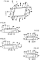
Fig. 1A is a plan view illustrating a block of a pneumatic tire according to a first exemplary embodiment. -
Fig. 1B is a drawing illustrating a first step portion and a second step portion provided at a block, as viewed alongarrow 1B inFig. 1A . -
Fig. 2A is a plan view illustrating a block of a pneumatic tire according to a second exemplary embodiment. -
Fig. 2B is an end-on view illustrating a second step portion provided at a block, as viewed alongarrow 2B inFig. 1A . -
Fig. 2C is an end-on view illustrating a first step portion provided at a block, as viewed along arrow 2C inFig. 1A . -
Fig. 3A is a plan view illustrating a block of a pneumatic tire according to a third exemplary embodiment. -
Fig. 3B is an end-on view illustrating a second step portion provided at a block, as viewed alongarrow 3B inFig. 3A . -
Fig. 3C is an end-on view illustrating a first step portion provided at a block, as viewed alongarrow 3C inFig. 3A . -
Fig. 3D is an end-on view illustrating a fourth step portion provided at a block, as viewed alongarrow 3D inFig. 3A . -
Fig. 3E is an end-on view illustrating a third step portion provided at a block, as viewed alongarrow 3E inFig. 3A . -
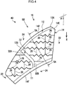
Fig. 4 ,Fig. 5A and Fig. 5B relate to a fourth exemplary embodiment.Fig. 4 is a plan view illustrating a block of a pneumatic tire. -
Fig. 5A is an enlarged cross-section illustrating a first step portion and a second step portion provided at a block, as viewed in the direction ofarrows 5A-5A inFig. 4 . -
Fig. 5B is an enlarged view illustrating a second step portion provided at a block, as viewed alongarrow 5B inFig. 4 . - Explanation follows regarding exemplary embodiments of the present invention, with reference to the drawings.
-
Fig. 1 illustrates apneumatic tire 10 according to the present exemplary embodiment, this being a snowtire including blocks 14, afirst step portion 11 extending along eachblock 14, and asecond step portion 12 extending along eachblock 14. Although plural of theblocks 14 are provided at atread 16, only one of theblocks 14 is illustrated in the drawings. Thefirst step portion 11 and thesecond step portion 12 are configured integrally to theblock 14. - The
blocks 14 are provided at thetread 16, and are demarcated by mutually intersecting main grooves that respectively extend around the tire circumferential direction and along the tire width direction. The main grooves are, for example, configured by circumferential directionmain grooves 22, and lateralmain grooves 24. In the present exemplary embodiment, the circumferential directionmain grooves 22 extend parallel to the tire circumferential direction, and the lateralmain grooves 24 extend parallel to the tire width direction. Eachblock 14 accordingly has a substantially rectangular shape in plan view. - The
first step portion 11 extends along aside wall portion 14F at one tire circumferential direction side of theblock 14, for example on the dig-in side in a tire rotation direction R. A height H1 of thefirst step portion 11 from agroove bottom 24A of the lateralmain groove 24 on theside wall portion 14F on the dig-in side is set lower than atread face 14A, and higher than thegroove bottom 24A. Specifically, inFig. 1B , H1 < H when H is a height of thetread face 14A of theblock 14 from thegroove bottom 24A. - The dig-in side refers to the side of the
block 14 that contacts the road surface first in the tire rotation direction R. - The
second step portion 12 extends along aside wall portion 14R at another tire circumferential direction side of theblock 14, for example on the kick-out side. A height H2 of thesecond step portion 12 from thegroove bottom 24A of the lateralmain groove 24 where theside wall portion 14R on the kick-out side is present is set lower than thetread face 14A, and higher than thegroove bottom 24A. Namely, inFig. 1B , H2 < H. - The kick-out side refers to the side of the
block 14 that is last to make contact (the side that is last to leave the road surface) in the tire rotation direction R. - The height H1 of the
first step portion 11 from thegroove bottom 24A and the height H2 of thesecond step portion 12 from thegroove bottom 24A are both from 50% to 80% of the height H from thegroove bottom 24A to thetread face 14A. The lower limit is set at 50% since below this value, the block rigidity becomes difficult to secure, and the upper limit is set at 80% since above this value, the increase in the volume of the lateralmain grooves 24 becomes small. - The height H2 of the
second step portion 12 from thegroove bottom 24A is greater than or equal to the height H1 of thefirst step portion 11, and the rigidity on thesecond step portion 12 side of theblock 14 is secured at that of thefirst step portion 11 side or greater. The relationship in size between the heights H1, H2 is more preferably H2 > H1. This thereby enables greater rigidity to be secured on the kick-out side of theblock 14. - The
second step portion 12 has a smaller width than thefirst step portion 11. More specifically, inFig. 1A , W2 < W1 when the width of thesecond step portion 12 is denoted W2, and the width of thefirst step portion 11 is denoted W1. Note that the widths W1, W2 respectively refer to the width in the tire circumferential direction in the cases of thefirst step portion 11 and thesecond step portion 12 that extend along the lateralmain grooves 24. - Explanation follows regarding operation of the present exemplary embodiment configured as described above. In
Fig. 1A and Fig. 1B , thepneumatic tire 10 according to the present exemplary embodiment is provided with thefirst step portion 11 and thesecond step portion 12 on eachblock 14 of thetread 16, and thefirst step portion 11 and thesecond step portion 12 are both set at a level lower than thetread face 14A. Moreover, the width W1 of thefirst step portion 11 is set larger than the width W2 of thesecond step portion 12. This secures a greater volume for the lateralmain grooves 24, and increases the shear force from snow columns in the lateralmain grooves 24, thereby enabling snow performance to be secured. - The width W2 of the
second step portion 12 is set smaller than the width W1 of thefirst step portion 11, and the rigidity of thesecond step portion 12 side (kick-out side) of theblock 14 is higher than that of thefirst step portion 11 side (dig-in side). Accordingly, when traction or braking force acts on thepneumatic tire 10, deformation of thesecond step portion 12 side (kick-out side) of theblock 14 is suppressed even when theblock 14 is dragged against the road surface. This thereby suppresses heel-and-toe wear of thepneumatic tire 10. - In particular, the height H2 of the
second step portion 12 from thegroove bottom 24A is set at from 50% to 80% of the height H from thegroove bottom 24A to the tread face, thereby enabling heel-and-toe wear to be more effectively suppressed, while improving snow performance. - In a
pneumatic tire 20 of the present exemplary embodiment illustrated inFig. 2A to Fig. 2C , the lateralmain grooves 24 are inclined with respect to the tire width direction. Theblock 14 accordingly has a substantially parallelogram shape in plan view, and anacute angle portion 14E is provided at a position on thesecond step portion 12 side of theblock 14 where an angle of intersection θ1 between the circumferential directionmain groove 22 and the lateralmain groove 24 on the kick-out side is an acute angle. - Widths W21, W22 of the
second step portion 12 are such that oneend 12A positioned on theacute angle portion 14E side is smaller than theother end 12B positioned on an opposite side from theacute angle portion 14E side. Specifically, inFig. 2A , W21 < W22 when the width of the oneend 12A of thesecond step portion 12 is denoted W21 and the width of theother end 12B is denoted W22. The widths W21, W22 of thesecond step portion 12 are smaller than the (uniform) width W1 of thefirst step portion 11, such that W21 < W22 < W1 when compared against the width W1. The width of thesecond step portion 12 gradually decreases on progression from theother end 12B (width W22) toward the oneend 12A (width W21). As an example, this change in width is linear; however it may also be on a curve. - The height of the
second step portion 12 from thegroove bottom 24A of the lateralmain groove 24 where theside wall portion 14R on the kick-out side is present is higher at the oneend 12A than at theother end 12B. Specifically, inFig. 2B , H21 > H22 when the height of the oneend 12A is denoted H21, and the height of theother end 12B is denoted H22. Including the height H1 of thefirst step portion 11 illustrated inFig. 2C , preferably H21 > H22 > H1. The height of thesecond step portion 12 gradually increases on progression from theother end 12B toward the oneend 12A. As an example, this change in height is linear; however it may also be on a curve. As illustrated inFig. 2C , the height H1 of thefirst step portion 11 is uniform. - Since other portions are similar to in the first exemplary embodiment, similar portions are allocated the same reference numerals, and explanation thereof is omitted.
- Explanation follows regarding operation of the present exemplary embodiment configured as described above. In the
pneumatic tire 20 according to the present exemplary embodiment illustrated inFig. 2A to 2C , theblock 14 includes theacute angle portion 14E. The width W21 of the oneend 12A positioned on theacute angle portion 14E side of thesecond step portion 12 is set smaller than the width W22 of theother end 12B positioned on the opposite side from theacute angle portion 14E. This accordingly secures the rigidity of theacute angle portion 14E. The width of thesecond step portion 12 gradually decreases on progression from theother end 12B toward the oneend 12A, giving a gentle change in the block rigidity along thesecond step portion 12. Specifically, there are no sudden changes in block rigidity in the range of thesecond step portion 12. - The height of the
second step portion 12 from thegroove bottom 24A of the main groove is set such that the height H21 of the oneend 12A is higher than the height H22 of theother end 12B, further securing the rigidity of theacute angle portion 14E. The height of thesecond step portion 12 gradually increases on progression from theother end 12B toward the oneend 12A, giving a gentle change in the block rigidity along thesecond step portion 12. - Accordingly, when traction or braking force acts on the
pneumatic tire 20, deformation of theacute angle portion 14E of theblock 14 is suppressed even when theblock 14 is dragged against the road surface. This thereby enables heel-and-toe wear to be suppressed even when theblock 14 includes theacute angle portion 14E. - In a
pneumatic tire 30 according to the present exemplary embodiment illustrated inFig. 3A to Fig. 3E , the lateralmain grooves 24 are inclined with respect to the tire width direction, and the main grooves extending in the tire circumferential direction, namely the circumferential directionmain grooves 22, are inclined with respect to the tire circumferential direction. Theblock 14 is provided with anacute angle portion 14G at a position on afourth step portion 34 side where an angle of intersection θ2 between the circumferential directionmain groove 22 and the lateralmain groove 24 is an acute angle. Respective tire width direction components arise at both tire width direction sides of theblock 14 due to force received from the road surface when travelling. In consideration of this, athird step portion 33 and thefourth step portion 34 are provided in addition to thefirst step portion 11 and thesecond step portion 12 of the second exemplary embodiment. - As illustrated in
Fig. 3A and Fig. 3D , thethird step portion 33 extends along awall portion 14S at one tire width direction side of theblock 14. Heights H31, H32 from agroove bottom 22A of the circumferential directionmain groove 22 where the oneside wall portion 14S is present, which are lower than thetread face 14A and higher than thegroove bottom 22A. Namely, inFig. 3C and Fig. 3D , H31 < H, and H32 < H. - As illustrated in
Fig. 3D , the height H31 is the height of one end positioned on theacute angle portion 14E side of thethird step portion 33, and the height H32 is the height of theother end 33B positioned on the opposite side from theacute angle portion 14E. The height H31 is higher than the height H32, namely, H31 > H32. - As illustrated in
Fig. 3A and Fig. 3E , thefourth step portion 34 extends along aside wall portion 14L at another tire width direction side of theblock 14. Heights H41, H42 from thegroove bottom 22A of the circumferential directionmain groove 22 where the otherside wall portion 14L is present, which are lower than thetread face 14A and higher than thegroove bottom 22A. Namely, inFig. 3C and Fig. 3E , H41 < H, and H42 < H. - As illustrated in
Fig. 3E , the height H41 is the height of oneend 34A positioned on theacute angle portion 14G side of thefourth step portion 34, and the height H42 is the height of theother end 34B positioned on an opposite side from theacute angle portion 14G side. The height of thefourth step portion 34 from thegroove bottom 22A is higher at the oneend 34A than at theother end 34B. Namely, H41 > H42. The height of thefourth step portion 34 from thegroove bottom 22A gradually increases on progression from theother end 34B toward the oneend 34A, giving a gentle change in the block rigidity along thefourth step portion 34. As an example, this change in height is linear; however it may also be on a curve. - The widths W41, W42 of the
fourth step portion 34 are set smaller than the width W3 of thethird step portion 33. Namely, W42 < W3, and W41 < W3. Specifically, inFig. 3A and Fig. 3E , W41 < W42 when the width of the oneend 34A of thefourth step portion 34 is denoted W41, and the width of theother end 34B is denoted W42. Since the widths W41, W42 of thefourth step portion 34 are smaller than the (uniform) width W3 of thethird step portion 33, when the width W3 is included, W41 < W42 < W3. The width of thefourth step portion 34 gradually decreases on progression from theother end 34B toward the oneend 34A. As an example, this change in width is linear; however it may also be on a curve. In the cases of thethird step portion 33 and thefourth step portion 34 extending along the circumferential directionmain grooves 22, the respective widths refer to the widths in the tire width direction. - The width W3 of the
third step portion 33 may be equal to the width W1 of thefirst step portion 11 as illustrated inFig. 3A , or may be different to the width W1. - As illustrated in
Fig. 3C , the height of thefirst step portion 11 from thegroove bottom 24A is higher at one end 11A than at theother end 11B. Specifically, H11 > H12 when the height of the one end 11A is denoted H11, and the height of theother end 11B is denoted H12. The height H32 of theother end 33B of thethird step portion 33 illustrated inFig. 3D is preferably higher than the height H12 of theother end 11B of thefirst step portion 11. - The heights H31, H32 of the
third step portion 33, and the heights H41, H42 of thefourth step portion 34, from thegroove bottom 22A, are each from 50% to 80% of the height H from thegroove bottom 22A to thetread face 14A. Note that the lower limit is set at 50% since below this value, block rigidity becomes difficult to secure, and the upper limit is set at 80% since above this value, the increase in the volume of the circumferential directionmain grooves 22 becomes small. - In the present exemplary embodiment, the one end 11A of the
first step portion 11 is connected to the oneend 34A of thefourth step portion 34, and theother end 11B is connected to theother end 33B of thethird step portion 33. The oneend 12A of thesecond step portion 12 is connected to oneend 33A of thethird step portion 33, and theother end 12B is connected to theother end 34B of thefourth step portion 34. - Since other portions are similar to in the first exemplary embodiment or the second exemplary embodiment, similar portions are allocated the same reference numerals, and explanation thereof is omitted.
- Explanation follows regarding operation of the present exemplary embodiment configured as described above. In the
pneumatic tire 30 according to the present exemplary embodiment illustrated inFig. 3A to Fig. 3E , theblock 14 of thetread 16 is provided not only with thefirst step portion 11 and thesecond step portion 12, but also with thethird step portion 33 and thefourth step portion 34. This accordingly secures a greater volume for the circumferential directionmain grooves 22 and the lateralmain grooves 24, and increases the shear force from snow columns in the circumferential directionmain grooves 22 and the lateralmain grooves 24, thereby enabling snow performance to be secured. - The
third step portion 33 and thefourth step portion 34 are provided at theside wall portions block 14, and the rigidity of theblock 14 is secured on thefourth step portion 34 side. Moreover, theblock 14 includes theacute angle portions acute angle portion 14E is secured by thesecond step portion 12, and the rigidity of theacute angle portion 14G is secured by thefourth step portion 34. The width of thefourth step portion 34 gradually decreases on progression from theother end 12B toward the oneend 12A, giving a gentle change in the block rigidity along thefourth step portion 34. Specifically, there are no sudden changes in block rigidity in the range of thefourth step portion 34. Moreover, the height of thefourth step portion 34 gradually increases on progression from theother end 34B toward the oneend 34A, giving a gentle change in the block rigidity along thefourth step portion 34. - Accordingly, when traction or braking force acts on the
pneumatic tire 30, deformation of theacute angle portion 14E of theblock 14 is suppressed even when theblock 14 is dragged against the road surface. Moreover, a tire width direction component arises in theblock 14 due to force received from the road surface when travelling, and when, for example, the side of the oneside wall portion 14S is the dig-in side, and the side of the otherside wall portion 14L is the kick-out side, deformation on thefourth step portion 34 side (kick-out side) of theblock 14 is suppressed. In particular, deformation of theacute angle portion 14G of theblock 14 is suppressed. This thereby enables heel-and-toe wear of thepneumatic tire 30 to be suppressed. - In a
pneumatic tire 40 according to the present exemplary embodiment, a more specific configuration of theblock 14 of the second exemplary embodiment is illustrated inFig. 4 andFigs. 5 . Theblock 14 is provided withplural sipes 26. Thetread 16 is configured including foam rubber. - The
sipes 26 are narrow grooves that open up when not in contact with the ground, and that close when in contact with the ground. Thesipes 26 extend in the tire width direction, for example, and are locally formed with zigzag shapes. - In addition to the
sipes 26, eachblock 14 is provided withlongitudinal sipes 28 and anarrow groove 32 in order to balance the rigidity of respective portions of theblock 14. Thelongitudinal sipes 28 extend around the tire circumferential direction, and cross theplural sipes 26. Thenarrow groove 32 is shallower than the circumferential directionmain grooves 22 and the lateralmain grooves 24, and crosses theblock 14 to open onto thefirst step portion 11 and thesecond step portion 12 respectively. Thenarrow groove 32 includes aninclined portion 32A that is inclined with respect to the tire circumferential direction, and astraight portion 32B that extends in the tire circumferential direction. As illustrated inFig. 5 , the groove bottom of thenarrow groove 32 is, for example, at a higher position than thefirst step portion 11 and thesecond step portion 12. This is so as to secure handling stability performance on dry road surfaces. - The one
end 12A of thesecond step portion 12 is positioned at the end portion on theacute angle portion 14E side of theblock 14, and theother end 12B of thesecond step portion 12 is positioned at the opening of thenarrow groove 32 onto thesecond step portion 12. Namely, thesecond step portion 12 is formed at a portion close to theacute angle portion 14E, rather than along the entireside wall portion 14R on the kick-out side. This is so as to secure braking performance on dry road surfaces. Thefirst step portion 11 is formed along the entireside wall portion 14F on the dig-in side. Edge removal is only performed locally, so as not to excessively reduce the rigidity of a narrow portion of theblock 14. - The
acute angle portion 14E, where theblock 14 is prone to low rigidity, is chamfered including at the oneend 12A of thesecond step portion 12 to remove the corner. - Note that the
sipes Fig. 5A for simplicity. - Since other portions are similar to in the first exemplary embodiment, similar portions are allocated the same reference numerals, and explanation thereof is omitted.
- Explanation follows regarding operation of the present exemplary embodiment configured as described above. The
pneumatic tire 40 illustrated inFig. 4 andFig. 5 is provided with theplural sipes 26, thereby enabling snow performance to be further improved due to the edge effect thereof. Theblock 14 includes theinclined portion 32A and thestraight portion 32B, thereby enabling shear force from snow columns to be secured within thenarrow groove 32. - The
tread 16 is moreover configured including foam rubber, thereby enabling improved driving performance on icy roads. - The
first step portion 11 secures snow performance, and thesecond step portion 12 suppresses heel-and-toe wear, similarly to in the second exemplary embodiment. - In the first exemplary embodiment, the height of the
second step portion 12 is greater than or equal to the height of thefirst step portion 11; however there is no limitation thereto, and the height of thesecond step portion 12 may be lower than the height of thefirst step portion 11 as long as block rigidity on thesecond step portion 12 side is secured. - In the
pneumatic tire 20 according to the second exemplary embodiment, the width of thesecond step portion 12 gradually decreases on progression from theother end 12B toward the oneend 12A; however, there is no limitation thereto, and for example, the width may decrease in steps. Similar also applies to the width of thefourth step portion 34 in the third exemplary embodiment. - The height of the
second step portion 12 is higher at the oneend 12A than at theother end 12B. However, there is no limitation thereto, and the height of thesecond step portion 12 may be uniform. The height of thesecond step portion 12 gradually increases on progression from theother end 12B toward the oneend 12A; however, there is no limitation thereto, and for example, the height may increase in steps. Similar also applies to the height of thefourth step portion 34 in the third exemplary embodiment. - The
pneumatic tire 30 according to the third exemplary embodiment is provided with thefirst step portion 11, thesecond step portion 12, thethird step portion 33, and thefourth step portion 34 around the periphery of theblock 14; however, there is no limitation thereto. In cases in which, for example, the circumferential directionmain grooves 22 have a greater angle of inclination with respect to the tire circumferential direction, and the oneside wall portion 14S corresponds to the dig-in side and the otherside wall portion 14L corresponds to the kick-out side, thethird step portion 33 and thefourth step portion 34 may be provided alone, omitting thefirst step portion 11 and thesecond step portion 12. Moreover, the height of thefourth step portion 34 may be uniform. - In each of the exemplary embodiments, for example, approximately half of the plural blocks 14 provided at the
tread 16 may be disposed facing in the other direction in the tire circumferential direction. So doing enables directionality of the tire to be avoided. - The configurations described in the respective exemplary embodiments may be combined and implemented as appropriate.
- Tires according to Comparative Examples 1 to 5 and Examples 1 to 6 were fitted to an actual vehicle and tested respectively for snowy road traction performance, braking performance on dry road surfaces, and for heel-and-toe anti-wear performance. Details of each test are as follows.
- For snow traction performance, test vehicles fitted with the respective tires travelled over snow at a vehicle speed of 5 km/h, before pressing the accelerator to accelerate and measuring the time required for the vehicle speed to reach 40 km/h (acceleration time), with the inverse of the acceleration time evaluated employing an index in which a conventional example is set to 100. The higher the number, the shorter the acceleration time and the higher the snow traction performance.
- For dry road surface braking performance, test vehicles fitted with the respective tires travelled at 100 km/h over a dry road surface, and the inverse of the stopping distance with the brakes fully applied (mm) was evaluated employing an index in which a Comparative Example 1 is set to 100. The greater the value, the better the dry braking performance.
- For heel-and-toe anti-wear performance, test vehicles fitted with the respective tires travelled for 2000 km at a constant speed of 60 km/h in various drive modes, on general roads in a dry state. For the presence or absence of heel-and-toe wear in the block, the block height on the kick-out side when new, and the block height on the kick-out side after wear were measured, and evaluation was made based on the difference between the heights. The smaller the difference in heights, the better the heel-and-toe anti-wear performance.
- Comparative Example 1 is a structure in which the
block 14 illustrated inFig. 4 does not have step portions on either of the dig-in side or the kick-out side. - Comparative Example 2 is provided with step portions of equal width and height on the dig-in side and the kick-out side of the blocks. The height of the step portions is 60% of the height from the groove bottom of the main grooves to the tread face.
- In Comparative Example 3, the height of a step portion on the kick-out side of the block from a reference of the groove bottom of a main groove is set to 48% of the height of the tread face.
- In Comparative Example 4 the similar height of a step portion is set to 49% of the height of the tread face.
- In Comparative Example 5, the similar height of a step portion is set to 81% of the height of the tread face.
- Example 1 has the
block 14 structure illustrated inFig. 4 . The height of thesecond step portion 12 on the kick-out side is 50% the height of thetread face 14A. - In Example 2, the similar height of a
second step portion 12 is set to 51 % the height of thetread face 14A. - In Example 3, the similar height of a
second step portion 12 is set to 79% the height of thetread face 14A. - In Example 4, the similar height of a
second step portion 12 is set to 80% the height of thetread face 14A. - Example 5 has a structure in which the width of the
second step portion 12 is set such that the width of the oneend 12A is smaller than the width of theother end 12B. - In Example 6, the shape of the
first step portion 11 of theblock 14 is modified. Specifically, as illustrated inFig. 3C , the height of thefirst step portion 11 on the dig-in side is higher at the one end 11A than at theother end 11B. - The results are shown in Table 1. Snow traction performance and dry road surface braking performance are shown using an index in which Comparative Example 1 is set to 100. The heel-and-toe anti-wear performance is evaluated using the three grades A, B, and C.
"A" means that heel-and-toe wear was not liable to occur, and wear was suppressed even when it did occur. "B" means that heel-and-toe wear was not liable to occur, however there was a high degree of wear when it did occur. "C" means that heel-and-toe wear occurred. - It can be seen from Table 1 that although Comparative Examples 2 to 5 exhibited improved dry road surface braking performance, there was a drop in snow traction performance, and the heel-and-toe anti-wear performance was evaluated as being poor. However, the tires according to Examples 1 to 6 not only exhibited snow traction performance and dry road surface braking performance equal to or better than that of Comparative Example 1, but heel-and-toe anti-wear performance was also evaluated highly.
Table 1 Snow traction performance Dry road surface braking performance Heel-and-toe anti-wear performance Comparative Example 1 100 100 B Comparative Example 2 90 108 C Comparative Example 3 98 115 C Comparative Example 4 98 115 C Comparative Example 5 95 110 B Example 1 108 99 A Example 2 108 99 A Example 3 100 108 A Example 4 100 108 A Example 5 105 105 A Example 6 108 108 A - The disclosure of
Japanese Patent Application No. 2013-123098, filed on June 11, 2013 - All cited documents, patent applications and technical standards mentioned in the present specification are incorporated by reference in the present specification to the same extent as if the individual cited document, patent application, or technical standard was specifically and individually indicated to be incorporated by reference.
-
- 10
- pneumatic tire
- 11
- first step portion
- 12
- second step portion
- 12A
- one end
- 12B
- other end
- 14
- block
- 14A
- tread face
- 14E
- acute angle portion
- 14F
- side wall portion
- 14G
- acute angle portion
- 14L
- side wall portion
- 14S
- side wall portion
- 14R
- side wall portion
- 16
- tread
- 20
- pneumatic tire
- 22
- circumferential direction main groove (main groove)
- 22A
- groove bottom
- 24
- lateral main groove (main groove)
- 24A
- groove bottom
- 26
- sipe
- 30
- pneumatic tire
- 33
- third step portion
- 33A
- one end
- 33B
- other end
- 34
- fourth step portion
- 34A
- one end
- 34B
- other end
- 40
- pneumatic tire
- W1
- Width
- W2
- Width
- W21
- Width
- W22
- Width
- W3
- Width
- W41
- Width
- W42
- Width
- θ1
- angle of intersection
- θ2
- angle of intersection
Claims (13)
- A pneumatic snow tire comprising:a block that is provided at a tread, and that is demarcated by mutually intersecting main grooves respectively extending around a tire circumferential direction and along a tire width direction;a first step portion that extends along a side wall portion at one tire circumferential direction side of the block, and that has a height from a groove bottom of the main groove, where the one side wall portion is present, which is lower than a tread face and higher than the groove bottom; anda second step portion that extends along a side wall portion at another tire circumferential direction side of the block, that has a height from a groove bottom of the main groove, where the other side wall portion is present, which is lower than the tread face and higher than the groove bottom, and that has a smaller width than the first step portion.
- The pneumatic tire of claim 1, wherein the height of the second step portion from the groove bottom is greater than or equal to the height of the first step portion.
- The pneumatic tire of either claim 1 or claim 2, wherein:the first step portion is provided on a dig-in side of the block; andthe second step portion is provided on a kick-out side of the block.
- The pneumatic tire of any one of claim 1 to claim 3, wherein:an acute angle portion is provided at a position on the second step portion side of the block where an acute angle of intersection is formed between the main grooves; andthe width of the second step portion is such that one end positioned on the acute angle portion side is smaller than another end positioned on an opposite side from the acute angle portion side.
- The pneumatic tire of claim 4, wherein the width of the second step portion gradually decreases on progression from the other end toward the one end.
- The pneumatic tire of either claim 4 or claim 5, wherein the height of the second step portion from the groove bottom is higher at the one end than at the other end.
- The pneumatic tire of claim 6, wherein the height of the second step portion from the groove bottom gradually increases on progression from the other end toward the one end.
- The pneumatic tire of any one of claim 1 to claim 7, wherein the height of the second step portion from the groove bottom is from 50% to 80% of a height from the groove bottom to the tread face.
- The pneumatic tire of any one of claim 1 to claim 8, wherein the main groove extending around the tire circumferential direction is inclined with respect to the tire circumferential direction, and the pneumatic tire further comprises:a third step portion that extends along a side wall portion at one tire width direction side of the block, and that has a height from a groove bottom of the main groove, where the one side wall portion is present, which is lower than the tread face and higher than the groove bottom; anda fourth step portion that extends along a side wall portion at another tire width direction side of the block, that has a height from a groove bottom of the main groove, where the other side wall portion is present, which is lower than the tread face and higher than the groove bottom, and that has a smaller width than the third step portion.
- The pneumatic tire of claim 9, wherein:an acute angle portion is provided at a position on the fourth step portion side of the block where an acute angle of intersection is formed between the main grooves; andthe width of the fourth step portion is such that one end positioned on the acute angle portion side is smaller than another end positioned on an opposite side from the acute angle portion side.
- The pneumatic tire of claim 10, wherein the width of the fourth step portion gradually decreases on progression from the other end toward the one end.
- The pneumatic tire of either claim 10 or claim 11, wherein the height of the fourth step portion from the groove bottom is higher at the one end than at the other end.
- The pneumatic tire of claim 12, wherein the height of the fourth step portion from the groove bottom gradually increases on progression from the other end toward the one end.
Applications Claiming Priority (2)
| Application Number | Priority Date | Filing Date | Title |
|---|---|---|---|
| JP2013123098A JP5577430B1 (en) | 2013-06-11 | 2013-06-11 | Pneumatic tire |
| PCT/JP2014/060034 WO2014199708A1 (en) | 2013-06-11 | 2014-04-04 | Pneumatic tire |
Publications (3)
| Publication Number | Publication Date |
|---|---|
| EP3009277A1 true EP3009277A1 (en) | 2016-04-20 |
| EP3009277A4 EP3009277A4 (en) | 2016-05-04 |
| EP3009277B1 EP3009277B1 (en) | 2017-06-21 |
Family
ID=51579071
Family Applications (1)
| Application Number | Title | Priority Date | Filing Date |
|---|---|---|---|
| EP14811548.8A Active EP3009277B1 (en) | 2013-06-11 | 2014-04-04 | Pneumatic tire |
Country Status (5)
| Country | Link |
|---|---|
| US (1) | US10052917B2 (en) |
| EP (1) | EP3009277B1 (en) |
| JP (1) | JP5577430B1 (en) |
| CN (1) | CN105283327B (en) |
| WO (1) | WO2014199708A1 (en) |
Families Citing this family (9)
| Publication number | Priority date | Publication date | Assignee | Title |
|---|---|---|---|---|
| JP6304329B2 (en) | 2016-08-31 | 2018-04-04 | 横浜ゴム株式会社 | Pneumatic tire |
| JP6848514B2 (en) * | 2017-02-22 | 2021-03-24 | 横浜ゴム株式会社 | Pneumatic tires |
| US10782908B2 (en) | 2018-02-05 | 2020-09-22 | Micron Technology, Inc. | Predictive data orchestration in multi-tier memory systems |
| US11099789B2 (en) | 2018-02-05 | 2021-08-24 | Micron Technology, Inc. | Remote direct memory access in multi-tier memory systems |
| US11416395B2 (en) | 2018-02-05 | 2022-08-16 | Micron Technology, Inc. | Memory virtualization for accessing heterogeneous memory components |
| US12135876B2 (en) | 2018-02-05 | 2024-11-05 | Micron Technology, Inc. | Memory systems having controllers embedded in packages of integrated circuit memory |
| CN109130708B (en) * | 2018-08-13 | 2024-08-06 | 厦门正新橡胶工业有限公司 | Tread pattern structure of pneumatic tire for dangerous pulling force vehicle |
| US11541693B2 (en) * | 2018-11-20 | 2023-01-03 | Sumitomo Rubber Industries, Ltd. | Tire |
| US10852949B2 (en) | 2019-04-15 | 2020-12-01 | Micron Technology, Inc. | Predictive data pre-fetching in a data storage device |
Family Cites Families (16)
| Publication number | Priority date | Publication date | Assignee | Title |
|---|---|---|---|---|
| CA1198043A (en) * | 1981-06-12 | 1985-12-17 | Barry W. Treves | Tyre treads |
| JPH0659765B2 (en) * | 1984-09-03 | 1994-08-10 | 住友ゴム工業株式会社 | Heavy vehicle tires |
| JPH0521441Y2 (en) * | 1986-03-18 | 1993-06-02 | ||
| JPH02303906A (en) * | 1989-05-18 | 1990-12-17 | Bridgestone Corp | Pneumatic tire |
| JP3024986B2 (en) * | 1990-08-16 | 2000-03-27 | 株式会社ブリヂストン | Pneumatic tire |
| JPH05338413A (en) * | 1992-06-10 | 1993-12-21 | Sumitomo Rubber Ind Ltd | Radial tire for heavy load |
| JPH0796716A (en) * | 1993-09-29 | 1995-04-11 | Yokohama Rubber Co Ltd:The | Pneumatic tire for heavy load |
| JP4390879B2 (en) | 1997-12-24 | 2009-12-24 | 株式会社ブリヂストン | Pneumatic tire |
| JP4472110B2 (en) * | 1999-10-21 | 2010-06-02 | 株式会社ブリヂストン | Pneumatic tire |
| JP4582578B2 (en) | 2004-11-10 | 2010-11-17 | 株式会社ブリヂストン | Block and pneumatic tire including the block |
| JP4968895B2 (en) * | 2006-09-25 | 2012-07-04 | 東洋ゴム工業株式会社 | Rough road running pneumatic tire |
| WO2008064703A1 (en) | 2006-11-30 | 2008-06-05 | Pirelli Tyre S.P.A. | Tire tread comprising blocks with stepped sidewalls |
| JP5303255B2 (en) | 2008-12-18 | 2013-10-02 | 株式会社ブリヂストン | Tires for motorcycles |
| JP2011046223A (en) * | 2009-08-25 | 2011-03-10 | Bridgestone Corp | Pneumatic tire |
| JP2011051431A (en) | 2009-08-31 | 2011-03-17 | Bridgestone Corp | Pneumatic tire |
| JP5461214B2 (en) * | 2010-02-01 | 2014-04-02 | 東洋ゴム工業株式会社 | Pneumatic tire |
-
2013
- 2013-06-11 JP JP2013123098A patent/JP5577430B1/en not_active Expired - Fee Related
-
2014
- 2014-04-04 CN CN201480033287.6A patent/CN105283327B/en active Active
- 2014-04-04 US US14/896,923 patent/US10052917B2/en active Active
- 2014-04-04 WO PCT/JP2014/060034 patent/WO2014199708A1/en not_active Ceased
- 2014-04-04 EP EP14811548.8A patent/EP3009277B1/en active Active
Also Published As
| Publication number | Publication date |
|---|---|
| US20160152086A1 (en) | 2016-06-02 |
| WO2014199708A1 (en) | 2014-12-18 |
| CN105283327A (en) | 2016-01-27 |
| JP5577430B1 (en) | 2014-08-20 |
| EP3009277B1 (en) | 2017-06-21 |
| JP2014240232A (en) | 2014-12-25 |
| US10052917B2 (en) | 2018-08-21 |
| EP3009277A4 (en) | 2016-05-04 |
| CN105283327B (en) | 2017-03-08 |
Similar Documents
| Publication | Publication Date | Title |
|---|---|---|
| EP3009277B1 (en) | Pneumatic tire | |
| JP5421135B2 (en) | Pneumatic tire | |
| RU2663960C2 (en) | Winter tire | |
| CN106994867B (en) | Pneumatic tire | |
| EP3000622B1 (en) | Pneumatic tire | |
| US9290061B2 (en) | Pneumatic tire | |
| US10266013B2 (en) | Pneumatic tire | |
| CN106042783B (en) | Pneumatic tire | |
| EP3081397A1 (en) | Pneumatic tire | |
| CN104175810B (en) | Pneumatic tire | |
| US11007820B2 (en) | Tire | |
| CN105459732B (en) | pneumatic tire | |
| US8794278B2 (en) | Pneumatic tire | |
| CN104723797A (en) | Pneumatic tire | |
| CN105636802B (en) | Pneumatic tire | |
| EP3375643A1 (en) | Tire | |
| US20150306917A1 (en) | Tire with rounded tread elements | |
| JP2016037083A (en) | Pneumatic tire | |
| EP3388254A1 (en) | Tire | |
| JP5560651B2 (en) | Pneumatic tire | |
| JP2015178337A (en) | pneumatic tire | |
| JP2013103567A (en) | Pneumatic tire | |
| JP5609263B2 (en) | Pneumatic tire | |
| CN110341393B (en) | Tyre | |
| JP5827661B2 (en) | Pneumatic tire |
Legal Events
| Date | Code | Title | Description |
|---|---|---|---|
| PUAI | Public reference made under article 153(3) epc to a published international application that has entered the european phase |
Free format text: ORIGINAL CODE: 0009012 |
|
| 17P | Request for examination filed |
Effective date: 20151231 |
|
| AK | Designated contracting states |
Kind code of ref document: A1 Designated state(s): AL AT BE BG CH CY CZ DE DK EE ES FI FR GB GR HR HU IE IS IT LI LT LU LV MC MK MT NL NO PL PT RO RS SE SI SK SM TR |
|
| AX | Request for extension of the european patent |
Extension state: BA ME |
|
| A4 | Supplementary search report drawn up and despatched |
Effective date: 20160405 |
|
| RIC1 | Information provided on ipc code assigned before grant |
Ipc: B60C 11/04 20060101ALI20160330BHEP Ipc: B60C 11/11 20060101AFI20160330BHEP Ipc: B60C 11/13 20060101ALI20160330BHEP |
|
| DAX | Request for extension of the european patent (deleted) | ||
| RIC1 | Information provided on ipc code assigned before grant |
Ipc: B60C 11/04 20060101ALI20161124BHEP Ipc: B60C 11/11 20060101AFI20161124BHEP Ipc: B60C 11/13 20060101ALI20161124BHEP Ipc: B60C 11/03 20060101ALI20161124BHEP |
|
| GRAP | Despatch of communication of intention to grant a patent |
Free format text: ORIGINAL CODE: EPIDOSNIGR1 |
|
| INTG | Intention to grant announced |
Effective date: 20170105 |
|
| GRAS | Grant fee paid |
Free format text: ORIGINAL CODE: EPIDOSNIGR3 |
|
| GRAA | (expected) grant |
Free format text: ORIGINAL CODE: 0009210 |
|
| AK | Designated contracting states |
Kind code of ref document: B1 Designated state(s): AL AT BE BG CH CY CZ DE DK EE ES FI FR GB GR HR HU IE IS IT LI LT LU LV MC MK MT NL NO PL PT RO RS SE SI SK SM TR |
|
| REG | Reference to a national code |
Ref country code: GB Ref legal event code: FG4D |
|
| REG | Reference to a national code |
Ref country code: CH Ref legal event code: EP |
|
| REG | Reference to a national code |
Ref country code: IE Ref legal event code: FG4D |
|
| REG | Reference to a national code |
Ref country code: AT Ref legal event code: REF Ref document number: 902592 Country of ref document: AT Kind code of ref document: T Effective date: 20170715 |
|
| REG | Reference to a national code |
Ref country code: SE Ref legal event code: TRGR |
|
| REG | Reference to a national code |
Ref country code: DE Ref legal event code: R096 Ref document number: 602014011092 Country of ref document: DE |
|
| REG | Reference to a national code |
Ref country code: NL Ref legal event code: MP Effective date: 20170621 |
|
| PG25 | Lapsed in a contracting state [announced via postgrant information from national office to epo] |
Ref country code: GR Free format text: LAPSE BECAUSE OF FAILURE TO SUBMIT A TRANSLATION OF THE DESCRIPTION OR TO PAY THE FEE WITHIN THE PRESCRIBED TIME-LIMIT Effective date: 20170922 Ref country code: LT Free format text: LAPSE BECAUSE OF FAILURE TO SUBMIT A TRANSLATION OF THE DESCRIPTION OR TO PAY THE FEE WITHIN THE PRESCRIBED TIME-LIMIT Effective date: 20170621 Ref country code: HR Free format text: LAPSE BECAUSE OF FAILURE TO SUBMIT A TRANSLATION OF THE DESCRIPTION OR TO PAY THE FEE WITHIN THE PRESCRIBED TIME-LIMIT Effective date: 20170621 Ref country code: NO Free format text: LAPSE BECAUSE OF FAILURE TO SUBMIT A TRANSLATION OF THE DESCRIPTION OR TO PAY THE FEE WITHIN THE PRESCRIBED TIME-LIMIT Effective date: 20170921 |
|
| REG | Reference to a national code |
Ref country code: LT Ref legal event code: MG4D |
|
| REG | Reference to a national code |
Ref country code: AT Ref legal event code: MK05 Ref document number: 902592 Country of ref document: AT Kind code of ref document: T Effective date: 20170621 |
|
| PG25 | Lapsed in a contracting state [announced via postgrant information from national office to epo] |
Ref country code: RS Free format text: LAPSE BECAUSE OF FAILURE TO SUBMIT A TRANSLATION OF THE DESCRIPTION OR TO PAY THE FEE WITHIN THE PRESCRIBED TIME-LIMIT Effective date: 20170621 Ref country code: LV Free format text: LAPSE BECAUSE OF FAILURE TO SUBMIT A TRANSLATION OF THE DESCRIPTION OR TO PAY THE FEE WITHIN THE PRESCRIBED TIME-LIMIT Effective date: 20170621 Ref country code: BG Free format text: LAPSE BECAUSE OF FAILURE TO SUBMIT A TRANSLATION OF THE DESCRIPTION OR TO PAY THE FEE WITHIN THE PRESCRIBED TIME-LIMIT Effective date: 20170921 Ref country code: NL Free format text: LAPSE BECAUSE OF FAILURE TO SUBMIT A TRANSLATION OF THE DESCRIPTION OR TO PAY THE FEE WITHIN THE PRESCRIBED TIME-LIMIT Effective date: 20170621 |
|
| PG25 | Lapsed in a contracting state [announced via postgrant information from national office to epo] |
Ref country code: SK Free format text: LAPSE BECAUSE OF FAILURE TO SUBMIT A TRANSLATION OF THE DESCRIPTION OR TO PAY THE FEE WITHIN THE PRESCRIBED TIME-LIMIT Effective date: 20170621 Ref country code: AT Free format text: LAPSE BECAUSE OF FAILURE TO SUBMIT A TRANSLATION OF THE DESCRIPTION OR TO PAY THE FEE WITHIN THE PRESCRIBED TIME-LIMIT Effective date: 20170621 Ref country code: RO Free format text: LAPSE BECAUSE OF FAILURE TO SUBMIT A TRANSLATION OF THE DESCRIPTION OR TO PAY THE FEE WITHIN THE PRESCRIBED TIME-LIMIT Effective date: 20170621 Ref country code: EE Free format text: LAPSE BECAUSE OF FAILURE TO SUBMIT A TRANSLATION OF THE DESCRIPTION OR TO PAY THE FEE WITHIN THE PRESCRIBED TIME-LIMIT Effective date: 20170621 Ref country code: CZ Free format text: LAPSE BECAUSE OF FAILURE TO SUBMIT A TRANSLATION OF THE DESCRIPTION OR TO PAY THE FEE WITHIN THE PRESCRIBED TIME-LIMIT Effective date: 20170621 |
|
| PG25 | Lapsed in a contracting state [announced via postgrant information from national office to epo] |
Ref country code: ES Free format text: LAPSE BECAUSE OF FAILURE TO SUBMIT A TRANSLATION OF THE DESCRIPTION OR TO PAY THE FEE WITHIN THE PRESCRIBED TIME-LIMIT Effective date: 20170621 Ref country code: PL Free format text: LAPSE BECAUSE OF FAILURE TO SUBMIT A TRANSLATION OF THE DESCRIPTION OR TO PAY THE FEE WITHIN THE PRESCRIBED TIME-LIMIT Effective date: 20170621 Ref country code: SM Free format text: LAPSE BECAUSE OF FAILURE TO SUBMIT A TRANSLATION OF THE DESCRIPTION OR TO PAY THE FEE WITHIN THE PRESCRIBED TIME-LIMIT Effective date: 20170621 Ref country code: IS Free format text: LAPSE BECAUSE OF FAILURE TO SUBMIT A TRANSLATION OF THE DESCRIPTION OR TO PAY THE FEE WITHIN THE PRESCRIBED TIME-LIMIT Effective date: 20171021 |
|
| REG | Reference to a national code |
Ref country code: DE Ref legal event code: R097 Ref document number: 602014011092 Country of ref document: DE |
|
| REG | Reference to a national code |
Ref country code: FR Ref legal event code: PLFP Year of fee payment: 5 |
|
| PLBE | No opposition filed within time limit |
Free format text: ORIGINAL CODE: 0009261 |
|
| STAA | Information on the status of an ep patent application or granted ep patent |
Free format text: STATUS: NO OPPOSITION FILED WITHIN TIME LIMIT |
|
| PG25 | Lapsed in a contracting state [announced via postgrant information from national office to epo] |
Ref country code: DK Free format text: LAPSE BECAUSE OF FAILURE TO SUBMIT A TRANSLATION OF THE DESCRIPTION OR TO PAY THE FEE WITHIN THE PRESCRIBED TIME-LIMIT Effective date: 20170621 |
|
| 26N | No opposition filed |
Effective date: 20180322 |
|
| PG25 | Lapsed in a contracting state [announced via postgrant information from national office to epo] |
Ref country code: SI Free format text: LAPSE BECAUSE OF FAILURE TO SUBMIT A TRANSLATION OF THE DESCRIPTION OR TO PAY THE FEE WITHIN THE PRESCRIBED TIME-LIMIT Effective date: 20170621 |
|
| PG25 | Lapsed in a contracting state [announced via postgrant information from national office to epo] |
Ref country code: MC Free format text: LAPSE BECAUSE OF FAILURE TO SUBMIT A TRANSLATION OF THE DESCRIPTION OR TO PAY THE FEE WITHIN THE PRESCRIBED TIME-LIMIT Effective date: 20170621 |
|
| REG | Reference to a national code |
Ref country code: CH Ref legal event code: PL |
|
| REG | Reference to a national code |
Ref country code: BE Ref legal event code: MM Effective date: 20180430 |
|
| GBPC | Gb: european patent ceased through non-payment of renewal fee |
Effective date: 20180404 |
|
| REG | Reference to a national code |
Ref country code: IE Ref legal event code: MM4A |
|
| PG25 | Lapsed in a contracting state [announced via postgrant information from national office to epo] |
Ref country code: LU Free format text: LAPSE BECAUSE OF NON-PAYMENT OF DUE FEES Effective date: 20180404 |
|
| PG25 | Lapsed in a contracting state [announced via postgrant information from national office to epo] |
Ref country code: GB Free format text: LAPSE BECAUSE OF NON-PAYMENT OF DUE FEES Effective date: 20180404 Ref country code: BE Free format text: LAPSE BECAUSE OF NON-PAYMENT OF DUE FEES Effective date: 20180430 Ref country code: CH Free format text: LAPSE BECAUSE OF NON-PAYMENT OF DUE FEES Effective date: 20180430 Ref country code: LI Free format text: LAPSE BECAUSE OF NON-PAYMENT OF DUE FEES Effective date: 20180430 |
|
| PG25 | Lapsed in a contracting state [announced via postgrant information from national office to epo] |
Ref country code: IE Free format text: LAPSE BECAUSE OF NON-PAYMENT OF DUE FEES Effective date: 20180404 |
|
| PG25 | Lapsed in a contracting state [announced via postgrant information from national office to epo] |
Ref country code: MT Free format text: LAPSE BECAUSE OF NON-PAYMENT OF DUE FEES Effective date: 20180404 |
|
| PG25 | Lapsed in a contracting state [announced via postgrant information from national office to epo] |
Ref country code: TR Free format text: LAPSE BECAUSE OF FAILURE TO SUBMIT A TRANSLATION OF THE DESCRIPTION OR TO PAY THE FEE WITHIN THE PRESCRIBED TIME-LIMIT Effective date: 20170621 |
|
| PG25 | Lapsed in a contracting state [announced via postgrant information from national office to epo] |
Ref country code: PT Free format text: LAPSE BECAUSE OF FAILURE TO SUBMIT A TRANSLATION OF THE DESCRIPTION OR TO PAY THE FEE WITHIN THE PRESCRIBED TIME-LIMIT Effective date: 20170621 |
|
| PG25 | Lapsed in a contracting state [announced via postgrant information from national office to epo] |
Ref country code: CY Free format text: LAPSE BECAUSE OF FAILURE TO SUBMIT A TRANSLATION OF THE DESCRIPTION OR TO PAY THE FEE WITHIN THE PRESCRIBED TIME-LIMIT Effective date: 20170621 Ref country code: MK Free format text: LAPSE BECAUSE OF NON-PAYMENT OF DUE FEES Effective date: 20170621 Ref country code: HU Free format text: LAPSE BECAUSE OF FAILURE TO SUBMIT A TRANSLATION OF THE DESCRIPTION OR TO PAY THE FEE WITHIN THE PRESCRIBED TIME-LIMIT; INVALID AB INITIO Effective date: 20140404 |
|
| PG25 | Lapsed in a contracting state [announced via postgrant information from national office to epo] |
Ref country code: AL Free format text: LAPSE BECAUSE OF FAILURE TO SUBMIT A TRANSLATION OF THE DESCRIPTION OR TO PAY THE FEE WITHIN THE PRESCRIBED TIME-LIMIT Effective date: 20170621 |
|
| P01 | Opt-out of the competence of the unified patent court (upc) registered |
Effective date: 20230531 |
|
| PGFP | Annual fee paid to national office [announced via postgrant information from national office to epo] |
Ref country code: FI Payment date: 20250424 Year of fee payment: 12 |
|
| PGFP | Annual fee paid to national office [announced via postgrant information from national office to epo] |
Ref country code: DE Payment date: 20250422 Year of fee payment: 12 |
|
| PGFP | Annual fee paid to national office [announced via postgrant information from national office to epo] |
Ref country code: IT Payment date: 20250424 Year of fee payment: 12 |
|
| PGFP | Annual fee paid to national office [announced via postgrant information from national office to epo] |
Ref country code: FR Payment date: 20250425 Year of fee payment: 12 |
|
| PGFP | Annual fee paid to national office [announced via postgrant information from national office to epo] |
Ref country code: SE Payment date: 20250429 Year of fee payment: 12 |