EP3009184A1 - Micro and nano bubble generating method, generating nozzle, and generating device - Google Patents
Micro and nano bubble generating method, generating nozzle, and generating device Download PDFInfo
- Publication number
- EP3009184A1 EP3009184A1 EP13886736.1A EP13886736A EP3009184A1 EP 3009184 A1 EP3009184 A1 EP 3009184A1 EP 13886736 A EP13886736 A EP 13886736A EP 3009184 A1 EP3009184 A1 EP 3009184A1
- Authority
- EP
- European Patent Office
- Prior art keywords
- liquid
- gas
- micro
- nano bubbles
- generating
- Prior art date
- Legal status (The legal status is an assumption and is not a legal conclusion. Google has not performed a legal analysis and makes no representation as to the accuracy of the status listed.)
- Granted
Links
Images









Classifications
-
- D—TEXTILES; PAPER
- D06—TREATMENT OF TEXTILES OR THE LIKE; LAUNDERING; FLEXIBLE MATERIALS NOT OTHERWISE PROVIDED FOR
- D06F—LAUNDERING, DRYING, IRONING, PRESSING OR FOLDING TEXTILE ARTICLES
- D06F35/00—Washing machines, apparatus, or methods not otherwise provided for
- D06F35/002—Washing machines, apparatus, or methods not otherwise provided for using bubbles
-
- B—PERFORMING OPERATIONS; TRANSPORTING
- B01—PHYSICAL OR CHEMICAL PROCESSES OR APPARATUS IN GENERAL
- B01F—MIXING, e.g. DISSOLVING, EMULSIFYING OR DISPERSING
- B01F23/00—Mixing according to the phases to be mixed, e.g. dispersing or emulsifying
- B01F23/20—Mixing gases with liquids
- B01F23/23—Mixing gases with liquids by introducing gases into liquid media, e.g. for producing aerated liquids
- B01F23/231—Mixing gases with liquids by introducing gases into liquid media, e.g. for producing aerated liquids by bubbling
- B01F23/23105—Arrangement or manipulation of the gas bubbling devices
- B01F23/2312—Diffusers
- B01F23/23121—Diffusers having injection means, e.g. nozzles with circumferential outlet
-
- A—HUMAN NECESSITIES
- A61—MEDICAL OR VETERINARY SCIENCE; HYGIENE
- A61L—METHODS OR APPARATUS FOR STERILISING MATERIALS OR OBJECTS IN GENERAL; DISINFECTION, STERILISATION OR DEODORISATION OF AIR; CHEMICAL ASPECTS OF BANDAGES, DRESSINGS, ABSORBENT PADS OR SURGICAL ARTICLES; MATERIALS FOR BANDAGES, DRESSINGS, ABSORBENT PADS OR SURGICAL ARTICLES
- A61L9/00—Disinfection, sterilisation or deodorisation of air
- A61L9/16—Disinfection, sterilisation or deodorisation of air using physical phenomena
- A61L9/18—Radiation
-
- B—PERFORMING OPERATIONS; TRANSPORTING
- B01—PHYSICAL OR CHEMICAL PROCESSES OR APPARATUS IN GENERAL
- B01F—MIXING, e.g. DISSOLVING, EMULSIFYING OR DISPERSING
- B01F23/00—Mixing according to the phases to be mixed, e.g. dispersing or emulsifying
- B01F23/20—Mixing gases with liquids
- B01F23/23—Mixing gases with liquids by introducing gases into liquid media, e.g. for producing aerated liquids
- B01F23/2319—Methods of introducing gases into liquid media
-
- B—PERFORMING OPERATIONS; TRANSPORTING
- B01—PHYSICAL OR CHEMICAL PROCESSES OR APPARATUS IN GENERAL
- B01F—MIXING, e.g. DISSOLVING, EMULSIFYING OR DISPERSING
- B01F23/00—Mixing according to the phases to be mixed, e.g. dispersing or emulsifying
- B01F23/20—Mixing gases with liquids
- B01F23/23—Mixing gases with liquids by introducing gases into liquid media, e.g. for producing aerated liquids
- B01F23/232—Mixing gases with liquids by introducing gases into liquid media, e.g. for producing aerated liquids using flow-mixing means for introducing the gases, e.g. baffles
- B01F23/2323—Mixing gases with liquids by introducing gases into liquid media, e.g. for producing aerated liquids using flow-mixing means for introducing the gases, e.g. baffles by circulating the flow in guiding constructions or conduits
-
- B—PERFORMING OPERATIONS; TRANSPORTING
- B01—PHYSICAL OR CHEMICAL PROCESSES OR APPARATUS IN GENERAL
- B01F—MIXING, e.g. DISSOLVING, EMULSIFYING OR DISPERSING
- B01F23/00—Mixing according to the phases to be mixed, e.g. dispersing or emulsifying
- B01F23/20—Mixing gases with liquids
- B01F23/23—Mixing gases with liquids by introducing gases into liquid media, e.g. for producing aerated liquids
- B01F23/237—Mixing gases with liquids by introducing gases into liquid media, e.g. for producing aerated liquids characterised by the physical or chemical properties of gases or vapours introduced in the liquid media
- B01F23/2373—Mixing gases with liquids by introducing gases into liquid media, e.g. for producing aerated liquids characterised by the physical or chemical properties of gases or vapours introduced in the liquid media for obtaining fine bubbles, i.e. bubbles with a size below 100 µm
-
- B—PERFORMING OPERATIONS; TRANSPORTING
- B01—PHYSICAL OR CHEMICAL PROCESSES OR APPARATUS IN GENERAL
- B01F—MIXING, e.g. DISSOLVING, EMULSIFYING OR DISPERSING
- B01F25/00—Flow mixers; Mixers for falling materials, e.g. solid particles
- B01F25/20—Jet mixers, i.e. mixers using high-speed fluid streams
- B01F25/23—Mixing by intersecting jets
-
- B—PERFORMING OPERATIONS; TRANSPORTING
- B01—PHYSICAL OR CHEMICAL PROCESSES OR APPARATUS IN GENERAL
- B01F—MIXING, e.g. DISSOLVING, EMULSIFYING OR DISPERSING
- B01F25/00—Flow mixers; Mixers for falling materials, e.g. solid particles
- B01F25/40—Static mixers
- B01F25/45—Mixers in which the materials to be mixed are pressed together through orifices or interstitial spaces, e.g. between beads
- B01F25/452—Mixers in which the materials to be mixed are pressed together through orifices or interstitial spaces, e.g. between beads characterised by elements provided with orifices or interstitial spaces
- B01F25/4521—Mixers in which the materials to be mixed are pressed together through orifices or interstitial spaces, e.g. between beads characterised by elements provided with orifices or interstitial spaces the components being pressed through orifices in elements, e.g. flat plates or cylinders, which obstruct the whole diameter of the tube
- B01F25/45211—Mixers in which the materials to be mixed are pressed together through orifices or interstitial spaces, e.g. between beads characterised by elements provided with orifices or interstitial spaces the components being pressed through orifices in elements, e.g. flat plates or cylinders, which obstruct the whole diameter of the tube the elements being cylinders or cones which obstruct the whole diameter of the tube, the flow changing from axial in radial and again in axial
-
- B—PERFORMING OPERATIONS; TRANSPORTING
- B01—PHYSICAL OR CHEMICAL PROCESSES OR APPARATUS IN GENERAL
- B01F—MIXING, e.g. DISSOLVING, EMULSIFYING OR DISPERSING
- B01F25/00—Flow mixers; Mixers for falling materials, e.g. solid particles
- B01F25/70—Spray-mixers, e.g. for mixing intersecting sheets of material
- B01F25/72—Spray-mixers, e.g. for mixing intersecting sheets of material with nozzles
-
- B—PERFORMING OPERATIONS; TRANSPORTING
- B01—PHYSICAL OR CHEMICAL PROCESSES OR APPARATUS IN GENERAL
- B01F—MIXING, e.g. DISSOLVING, EMULSIFYING OR DISPERSING
- B01F35/00—Accessories for mixers; Auxiliary operations or auxiliary devices; Parts or details of general application
- B01F35/30—Driving arrangements; Transmissions; Couplings; Brakes
- B01F35/32—Driving arrangements
- B01F35/32005—Type of drive
- B01F35/3204—Motor driven, i.e. by means of an electric or IC motor
-
- B—PERFORMING OPERATIONS; TRANSPORTING
- B01—PHYSICAL OR CHEMICAL PROCESSES OR APPARATUS IN GENERAL
- B01F—MIXING, e.g. DISSOLVING, EMULSIFYING OR DISPERSING
- B01F35/00—Accessories for mixers; Auxiliary operations or auxiliary devices; Parts or details of general application
- B01F35/30—Driving arrangements; Transmissions; Couplings; Brakes
- B01F35/32—Driving arrangements
- B01F35/32005—Type of drive
- B01F35/32045—Hydraulically driven
-
- B—PERFORMING OPERATIONS; TRANSPORTING
- B01—PHYSICAL OR CHEMICAL PROCESSES OR APPARATUS IN GENERAL
- B01J—CHEMICAL OR PHYSICAL PROCESSES, e.g. CATALYSIS OR COLLOID CHEMISTRY; THEIR RELEVANT APPARATUS
- B01J19/00—Chemical, physical or physico-chemical processes in general; Their relevant apparatus
- B01J19/26—Nozzle-type reactors, i.e. the distribution of the initial reactants within the reactor is effected by their introduction or injection through nozzles
-
- B—PERFORMING OPERATIONS; TRANSPORTING
- B01—PHYSICAL OR CHEMICAL PROCESSES OR APPARATUS IN GENERAL
- B01J—CHEMICAL OR PHYSICAL PROCESSES, e.g. CATALYSIS OR COLLOID CHEMISTRY; THEIR RELEVANT APPARATUS
- B01J7/00—Apparatus for generating gases
-
- C—CHEMISTRY; METALLURGY
- C02—TREATMENT OF WATER, WASTE WATER, SEWAGE, OR SLUDGE
- C02F—TREATMENT OF WATER, WASTE WATER, SEWAGE, OR SLUDGE
- C02F1/00—Treatment of water, waste water, or sewage
- C02F1/34—Treatment of water, waste water, or sewage with mechanical oscillations
-
- C—CHEMISTRY; METALLURGY
- C02—TREATMENT OF WATER, WASTE WATER, SEWAGE, OR SLUDGE
- C02F—TREATMENT OF WATER, WASTE WATER, SEWAGE, OR SLUDGE
- C02F1/00—Treatment of water, waste water, or sewage
- C02F1/72—Treatment of water, waste water, or sewage by oxidation
-
- B—PERFORMING OPERATIONS; TRANSPORTING
- B01—PHYSICAL OR CHEMICAL PROCESSES OR APPARATUS IN GENERAL
- B01F—MIXING, e.g. DISSOLVING, EMULSIFYING OR DISPERSING
- B01F2101/00—Mixing characterised by the nature of the mixed materials or by the application field
- B01F2101/48—Mixing water in water-taps with other ingredients, e.g. air, detergents or disinfectants
-
- B—PERFORMING OPERATIONS; TRANSPORTING
- B01—PHYSICAL OR CHEMICAL PROCESSES OR APPARATUS IN GENERAL
- B01J—CHEMICAL OR PHYSICAL PROCESSES, e.g. CATALYSIS OR COLLOID CHEMISTRY; THEIR RELEVANT APPARATUS
- B01J2219/00—Chemical, physical or physico-chemical processes in general; Their relevant apparatus
- B01J2219/00049—Controlling or regulating processes
- B01J2219/00162—Controlling or regulating processes controlling the pressure
-
- C—CHEMISTRY; METALLURGY
- C02—TREATMENT OF WATER, WASTE WATER, SEWAGE, OR SLUDGE
- C02F—TREATMENT OF WATER, WASTE WATER, SEWAGE, OR SLUDGE
- C02F1/00—Treatment of water, waste water, or sewage
- C02F1/72—Treatment of water, waste water, or sewage by oxidation
- C02F1/722—Oxidation by peroxides
-
- C—CHEMISTRY; METALLURGY
- C02—TREATMENT OF WATER, WASTE WATER, SEWAGE, OR SLUDGE
- C02F—TREATMENT OF WATER, WASTE WATER, SEWAGE, OR SLUDGE
- C02F1/00—Treatment of water, waste water, or sewage
- C02F1/72—Treatment of water, waste water, or sewage by oxidation
- C02F1/76—Treatment of water, waste water, or sewage by oxidation with halogens or compounds of halogens
-
- C—CHEMISTRY; METALLURGY
- C02—TREATMENT OF WATER, WASTE WATER, SEWAGE, OR SLUDGE
- C02F—TREATMENT OF WATER, WASTE WATER, SEWAGE, OR SLUDGE
- C02F1/00—Treatment of water, waste water, or sewage
- C02F1/72—Treatment of water, waste water, or sewage by oxidation
- C02F1/78—Treatment of water, waste water, or sewage by oxidation with ozone
-
- C—CHEMISTRY; METALLURGY
- C02—TREATMENT OF WATER, WASTE WATER, SEWAGE, OR SLUDGE
- C02F—TREATMENT OF WATER, WASTE WATER, SEWAGE, OR SLUDGE
- C02F2303/00—Specific treatment goals
- C02F2303/04—Disinfection
Definitions
- the present invention relates to a method for, a bubble generating nozzle for, and an apparatus for generating micro-nano bubbles, wherein the method, the nozzle, and the apparatus use water hammering.
- washing or sterilizing by micro-nano bubbles is a method that uses only water, air, and additives of a trace quantity, offering a reduced environmental load. Due to this, such method have attracted attention as an alternative to a conventional method for washing or sterilizing that uses materials like detergents and chemicals. In addition, because of such method being highly safe, application as a sterilization method for vegetables and foods has been studied. Conventional methods for generating micro-nano bubbles have been known in three fashions: the gas-liquid two-phase swirl flow method, the venturi tube method, and the pressure dissolution method. (For example, refer to Patent Literatures 1 and 2 for the gas-liquid two-phase swirl flow method and the pressure dissolution method.)
- Pumps of various types are employable as the driving pump in an apparatus that generates bubbles using water, air, and additives of a trace quantity.
- washing and sterilization of semiconductor devices and food require that all the pertinent apparatus components including the driving pump should operate without causing metal contamination.
- all the wetted parts of pumps to be used in an apparatus for generating micro-nano bubbles should be made of those which do not generate any metal ions; and further, such pumps must operate stably at a discharge pressure of 0.3 to 0.6 MPa.
- Patent Literatures 3 and 4 have proposed an apparatus that employs a compressed-air driven bellows-cylinder pump as a pump that feeds liquid without using rotating movements. All the wetted parts of the proposed pump are made of fluorine resin to avoid the feared metal contamination that will occur in a rotating type pump. To achieve the goal of performing a clean washing without the influence of contamination, technical development is desired on application of plastic by use of such as fluorine resin to all the related constituent units for generating micro-bubbles, including not only pumps but also nozzles.
- micro-nano bubbles In conventional technologies, it is extremely difficult to generate a large amount of micro-nano bubbles only with pure water but without using nucleating agent. Granted that addition of a nucleating agent is intended, the agent is required to be used in a significantly reduced amount. In addition, if micro-nano bubbles can be generated in an amount considerably larger than a quantity that conventional technologies will generate, great improvement in washing and sterilization can be expected and, further, the broadening of application of such technique to various usages becomes practicable. Thus, a method for generating micro-nano bubbles by a new technique instead of prior arts and an apparatus for generating micro-nano bubbles capable of actualizing such new technique have been strongly desired.
- an object of the present invention is to provide an apparatus for generating micro-nano bubbles to construct a system that performs clean washing and sterilizing with large amount of micro-nano bubbles generated using pure water only and can generate micro-nano bubbles without metal contamination.
- the apparatus intended to be provided including a bubble generating nozzle and an auto-regulating gas-liquid mixing vessel is to operate on a new method, which is different from conventional arts, for generating micro-nano bubbles using water hammering.
- the basic idea for solving the problem described above is use of violent water hammering to generate a large amount of micro-nano bubbles that contains dissolved gas, wherein the water hammering occurs on collision of water, a non-compressive substance.
- the inventors of the present invention has been led to the present art through, in the method for generating micro-nano bubbles and the apparatus therefor, optimizing the structure and the shape of the bubble generating nozzle so that the water hammering power will work to its utmost extent and constructing an apparatus for generating micro-nano bubbles having a configuration that accelerates generating large amount of micro-nano bubbles.
- the method for generating micro-nano bubbles by the present invention generates micro-nano bubbles using the water hammering power. Therefore, the method is able to generate micro-nano bubbles in a large amount using pure water only without use of substances which are not necessarily needed such as nucleating agents. Accordingly, the method can realize a clean washing and sterilization. Since this water hammering power is maximized by the use of a bubble-generating nozzle having an optimized structure and shape, the use of such optimized nozzle makes it possible to perform continuous and stable generation of bubbles in an efficient manner. Thereby, the amount of generation of small-size bubbles, not only of the size of micrometer order but also of nanometer order, can be increased together. This feature enhances the capability and function in the washing and sterilizing more than those in conventional technique.
- the apparatus for generating micro-nano bubbles by the present invention has a bubble generating nozzle and equipment configuration that permits the generating of bubbles in a large amount stably; therefore, the apparatus is usable in a set of equipment for clean washing and sterilizing with pure water.
- the gas-liquid mixing vessel that dissolves gas in liquid
- transferring gas and liquid in a lump by a pump may sometimes prevent generating uniform micro-nano bubbles.
- This problem is solvable by discharging excess gas from the gas-liquid mixing vessel through a float valve provided inside or outside the vessel. With this float valve, the volume of the gas and the liquid are maintained always within a prescribed range and thereby the amount of generation of the micro-nano bubbles becomes constant.
- the method and the apparatus by the present invention contribute to constructing a micro-nano bubble generating system that generates bubbles without metal contaminations.
- application of the present invention to washing such as semiconductor wafers simplifies such washing process compared to conventional processes that perform complicated washing using such as drug solutions.
- the invention is cable of reducing environmental load because the invented method does not need use of material such as drug solutions.
- the use of the invention for sterilization of foods such as vegetables makes it possible to perform reliable and safe sterilization.
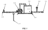
- FIG. 1 is a front view of the micro-nano bubble generating system to which the present invention is applied and FIG. 2 is a perspective view of the same.
- Each of the reference numerals therein denotes; 15: a bellows cylinder pump, 13: a pump controller, 14: a gas-liquid mixing vessel, 12: a pressure sensor, 11: a micro-nano bubble generating nozzle attachment part, 17: a liquid sucking pipe, 16: a gas sucking port, and 18: a gas sucking regulating valve.
- the bellows cylinder pump 15 wetted parts of which are made of fluorine resin, sucks gas and liquid into the pump in a mixture state through the liquid sucking pipe 17 and the gas sucking regulating valve 18, with the volume of the gas regulated.
- the sucked liquid and gas mixture is agitated and compressed inside the bellows to dissolve the gas in the liquid.
- the bellows cylinder pump 15 has a metal free structure, such configuration is enough. Any plastic other than fluorine resin can also be useable.
- Usable plastic includes at least one of plastics selected from the group consisting of, for example: general purpose plastics such as polyethylene, polypropylene, and polyethylene terephthalate; engineering plastics such as polyacetar, polyamide, polycarbonate, and denaturing polyphenylene ether; and super engineering plastics such as polyether sulfone, polyphenylene sulfide, polyether ether ketone, and liquid crystal polymer.
- general purpose plastics such as polyethylene, polypropylene, and polyethylene terephthalate
- engineering plastics such as polyacetar, polyamide, polycarbonate, and denaturing polyphenylene ether
- super engineering plastics such as polyether sulfone, polyphenylene sulfide, polyether ether ketone, and liquid crystal polymer.
- plastics selected from the group consisting of, for example: general purpose plastics such as polyethylene, polypropylene, and polyethylene terephthalate; engineering plastics such as polyacetar, polyamide, polycarbon
- the pump 15 used is mainly a bellows cylinder pump of compressed-air driven type but an electric motor driven type may be used.
- the gas and the liquid in the gas-liquid mixing vessel 14 are under the pressure generated by the pump 15; therefore, the gas is easily dissolved.
- the pressure that force-feeds the gas and the liquid from the pump 15 is watched by the pressure sensor 12.
- Increasing the quantity of the dissolved gas with this manner the preparations are made for increasing the amount of generation of the micro-nano bubbles.
- the applicable pumps include a reciprocating pump such as a piston pump, a plunger pump, or a diaphragm pump; or a rotary pump such as a gear pump, an eccentric pump, or a screw pump.
- the liquid entered under force-feeding the gas-liquid mixing vessel 14 mixes with gas to dissolve the gas thereinto and then is transferred to the micro-nano bubble generating nozzle attachment part 11.
- the micro-nano bubble generating nozzle attachment part 11 is a part to which a nozzle connects, wherein the nozzle generates, from the gas-dissolved liquid, micro-nano bubbles in a large amount having a diameter of 60 ⁇ m or smaller, preferably to be 15 ⁇ m or smaller.
- the pressure sensor 12 senses variation of the liquid pressure at the section between the micro-nano bubble generating nozzle attachment part 11 and the gas-liquid mixing vessel 14 to watch the dissolving conditions of the gas-liquid. By this, a constant pressure condition needed for stable generation of micro-nano bubbles is actualized.
- the process to be performed by the apparatus for generating micro-nano bubbles to which the present invention is applied is as follows. Treatments that the gas sucking port 16, the liquid sucking pipe 17, and the gas sucking regulating valve 18 perform are the gas- and liquid-sucking process. The pressure is regulated by the pressure sensor 12. Next, the gas-including liquid is pressurized using the bellows cylinder pump 15; this treatment is the gas-liquid pressurization process. Following this process, the pressurized gas-including liquid is mixed with another new gas using the pump controller 13 and the gas-liquid mixing vessel 14; this treatment is the dissolved gas enriching process.
- the bubble generating nozzle by the present invention which nozzle will be mentioned later, is connected to the micro-nano bubble generating nozzle attachment part 11 to generate micro-nano bubbles.
- This process is referred to as the dissolved liquid miniaturization process, in which the micro-nano bubbles are generated by injecting the dissolved liquid from the outside of a cylinder, which has two or more small through-holes, via such small through-holes at a pressure higher than the atmospheric pressure to produce jets of the liquid, and the jets are collided mutually at one point inside the cylinder.
- FIG. 3 is a cross sectional view of the micro-nano bubble generating nozzle including an attachment part.
- reference numerals 1 and 2 are the outer cases of the nozzle, which are disposed facing each other and fastened together using a bolt 8 and a nut 9, wherein the dissolved liquid force-fed by the pump is divided into two streams and each of the streams is separately introduced into the outer cases 1 and 2 as arrows show.
- a recess is provided to accommodate the high-speed liquid jet squirting nozzle parts 3 and 4.
- the size of the nozzle hole determines the flow rate and the flow velocity of the liquid discharge.
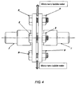
- FIG. 4 illustrates the nozzle in the fabricated state, in which the bolt 8 is tightening-fastened by the nut 9.
- the water that produced micro-nano bubble is discharged in the radial direction indicated by arrows.
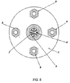
- FIG. 5 is a side view of the micro-nano bubble generating nozzle by high-speed liquid jet squirting, in which the micro-nano bubble water is discharged in the circumferential direction.
- the following explains how to generate the micro-nano bubbles using the water stream squirted from the high-speed liquid jet squirting nozzle.
- the gas-dissolved liquid is discharged from the high-speed liquid jet squirting nozzle at the discharge pressure of 0.2 MPa to 0.6 MPa given by the high-pressure pump 15.
- the discharged liquid rapidly releases its pressure and collides violently each other producing a water hammering power.
- the explosive water hammering smashes the gas-dissolve liquid and makes the liquid to be in a state that a large amount of micro-nano bubbles is involved therein.
- the amount of generation of micro-nano bubbles becomes reduced.
- the micro-nano bubbles can be generated in a large amount with the method and the apparatus by the present invention.
- FIG. 6 is a cross sectional view taken along the line B-B and an outline view of the high-speed liquid jet squirting nozzle parts 3 and 4 that generate micro-nano bubbles.
- the high-speed liquid jet squirting nozzle parts 3 and 4 are, as illustrated in the cross sectional view, centered relying on the centering pin 5, which defines the center, and positioned guided by the positioning pins 6 and 7, and then fixed.
- the high-speed liquid jet squirting nozzle parts 3 and 4 generate the micro-nano bubbles.
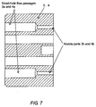
- FIG. 7 is an enlarged cross sectional view of the high-speed liquid jet squirting nozzle parts 3 and 4 illustrated in FIG. 6 . Since these parts 3 and 4 have the same shape and disposed symmetrically, the following explains using reference numerals 3 and 4 for simplicity.
- the liquid stream is narrowed at small-hole flow passages 3a and 4a. Thereby the jet stream squirts from the end of small-hole flow passages 3a and 4a that narrow the liquid stream.
- Nozzle parts 3b and 4b are arranged so that the jets squirted from each of the high-speed liquid jet squirting nozzle parts 3 and 4 collide, producing micro-nano bubbles from the collided gas-dissolved liquid.
- the micro-nano bubbles that involve gas inside diffuse in the circumferential direction indicated by arrows.
- the reason of feeding the liquid at a high-pressure is to increase the speed of the liquid in squirting from the small-hole. This means that making the liquid collision high-speed increases the impact energy and that a large amount of micro-nano bubbles of more minute size can be generated thereby.
- the amount of generation of micro-nano bubbles can be made equal to or more than the conventional quantity when the pressure of squirting the dissolved liquid of the gas-liquid mixing state is the atmospheric pressure (about 0.1 MPa) or more. Further, setting the pressure to 0.2 MPa or higher makes it possible to generate micro-nano bubbles in an amount sufficient for performing clean washing and sterilizing. As mentioned above in the present invention, the lower limit of the squirting pressure of the dissolved liquid can be set to 0.2 MPa, a lower value than the conventional pressure.
- the compressed-air driven or electric-motor driven bellows cylinder pump 15 made of fluorine resin As shown in FIGS. 1 and 2 .
- the squirting pressure of the dissolved liquid exceeds 0.6 MPa while using the compressed-air driven or electric-motor driven bellows cylinder pump of the present invention, the amount of generation of micro-nano bubbles tends to be saturated. Therefore, the squirting pressure of the dissolved liquid in the present invention is preferred to be 0.2 to 0.6 MPa.
- the micro-nano bubble generating nozzle by the present invention needs to have a diameter of 0.1 to 6 mm at its nozzle parts 3b and 4b shown in FIG. 7 so as to squirt the jet of the dissolved liquid in a pressure higher than the atmospheric pressure, preferably 0.2 to 0.6 MPa, which are lower than conventional pressures.
- the openings of the nozzle parts 3b and 4b, from which the jet stream squirts, and the diameters of the nozzle parts 3b and 4b correspond to the "spout" and the "diameter of the small through-holes of the nozzle at the part leading to the hollow of the cylinder" respectively, as the present invention defines.
- the reason for specifying the diameter of the nozzle parts 3b and 4b to be 0.1 to 6 mm will be detailed in the description of embodiment example later.
- the small-hole flow passages 3a and 4a are enough when they are such a device as has a stream-narrowing function for feeding the gas-dissolved liquid in a form of a high-speed jet; and when they are taper-shaped continuously toward the nozzle parts 3b and 4b, they may also be enough.
- the amount of generation of micro-nano bubbles is determined mainly by the dimension of the diameter of the nozzle parts 3b and 4b; therefore, the small-hole flow passages 3a and 4a may be omitted in the present invention.
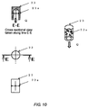
- FIG. 8 Illustrated in FIG. 8 is the nozzle for generating micro-nano bubbles, which is comprised of a nozzle case 21, a micro-nano bubble discharging nozzle 22, and a base 24, wherein one or more liquid-collision nozzles 23 are installed on the base 24.
- FIG. 9 is an enlarged view of the part where the liquid-collision nozzle 23 shown in FIG. 8 is disposed.
- FIG. 10 illustrates the shape of a single piece of the liquid-collision nozzle 23.
- a small-hole 23a opens toward the center of the liquid-collision nozzle 23.
- High-pressure liquid entering through this small-hole at a high-pressure in the direction of the arrow Q collides in the center of the liquid-collision nozzle 23, generating micro-nano bubbles.
- FIG. 10 illustrates the shape of the liquid-collision nozzles 23, wherein a small-hole 23a is made in the circumference of the nozzle-cylinder part of the liquid-collision nozzle 23. Through this small-hole, the dissolved liquid squirts to collide in the center and generates micro-nano bubbles. The micro-nano bubbles thus generated is discharged toward the arrow Q. When a plurality of the liquid-collision nozzle 23 is gather-arrayed, a large amount of micro-nano bubbles are generated and are discharged from a nozzle part 22a of the discharging nozzle 22 illustrated in FIG. 8 . As illustrated in FIG.
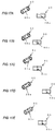
- the shape of a liquid-collision nozzle 25 is such a shape as has small-holes 25a in a multi-row configuration. For example therefore, when three places are provided for producing the water hammering by making holes in a three-row configuration, it becomes practicable to generate micro-nano bubbles in a large amount. Thus, this practice is a useful method for miniaturization and increased efficiency.
- Discharging the liquid from a plurality of holes increases the intensity of the water hammering.
- Using this technique will not decrease the amount of generation of micro-nano bubbles even if the velocity V is low; and consequently a pump with a high discharging pressure is not needed, which imposes less defrayment.
- this technique is industrially very useful and permits development of a nozzle having good efficiency.
- FIG. 12 is a cross sectional view of the gas-liquid mixing vessel 14.
- FIG. 13 is an enlarged view of the circled area E in FIG. 12 .
- a conventional gas-liquid mixing vessel wherein gas and liquid are mixed under a high pressure, the mixture of gas and pure water is fed into the gas-liquid mixing vessel by a pump and spouted therein upward like a water spout to merge the mixture.
- This method however is not efficient in mixing; therefore it is necessary to generate micro-nano bubbles in an increased amount for improved efficiency.
- gas and liquid are fed by a pump in the direction of the arrow A toward the arrow B and are introduced into gas-liquid injection pipes 32 and 33.
- water hammering produced by colliding liquid in the directions from the arrow X and the arrow Y is used for increased efficiency of the mixing of the gas and liquid discharged from a hole of gas-liquid injection pipe 32a and a hole of gas-liquid injection pipe 33a of the gas-liquid injection pipe 33.
- mixing gas and liquid is performed efficiently and gas-liquid mixture liquid as a raw material of micro-nano bubbles is produced speedily with increased merging rate.
- a float 31 illustrated in FIG. 12 is provided for the purpose of exhausting excessively entered gas to outside if gas enters excessively in mixing gas and liquid.
- the float 31 exhausts entered excess gas safely and regulates the amount of gas and liquid to a proper level. This means that a certain situation is produced as described below. If there remains undissolved gas due to the entering of excessive amount of gas, the gas will flow into the nozzle and impedes the generation of micro-nano bubbles.
- the float eliminates this adverse effect of impeding bubble generation and controls the amount of generation of the micro-nano bubbles to a proper level, enabling sending bubbles stably.
- FIG. 14 illustrates a cross sectional view of a part of the float 31 shown in FIG. 12 .
- the structure of the float pipe 31 comprises a float tip part 31a (which is tapered toward its end), a reinforcing rib 31b for prevention of collapse by the pressure of liquid, and a stop plug 31c.
- the float 31 may be installed outside the gas-liquid mixing vessel, instead of installing inside. In this arrangement, connecting the inside and outside of the gas-liquid mixing vessel using such as a communication pipe permits controlling the volume ratio of gas and liquid.
- FIG. 15 is an example of a gas-liquid mixing vessel that has more improved efficiency.
- This vessel is a gas-liquid mixing vessel structured based on a gas-liquid mixing vessel comprising a gas-liquid mixing vessel outer frame 36, a micro-nano bubble generating nozzle 38, and a member 40, wherein a structure resistible to the internal pressure of the gas-liquid mixing vessel is given to the basic structure. The mixing of gas and liquid is efficiently performed inside that vessel.
- each of the reference numerals denotes:
- a major method for generating an increased amount of micro-nano bubbles is as follows.
- the method is comprised of processes of: generating micro-nano bubbles once in a water tank; pumping up micro-nano bubbles generated in the water tank again; injecting additional gas to be dissolved into the pumped bubble-containing liquid at the gas-liquid mixing vessel; and circulating the gas-injected bubble-containing liquid multiple times to bring the bubble-containing liquid to a state in which a large amount of micro-nano bubbles are involved.
- micro-nano bubbles are generated in an increased amount.
- micro-nano bubbles without circulation in the gas-liquid mixing vessel to be used in the present invention, by a liquid-collision in the gas-liquid mixture state under the working of the micro-nano bubble generating nozzle 38, which is held on a nozzle holder 39, having a structure same as illustrated in FIG. 8 .
- the nozzle 38 arranged inside the gas-liquid mixing vessel should issue the dissolved liquid of the gas-liquid mixture state at a flow rate more than that of the nozzle 11 arranged at the distal end to increase the pressure inside the gas-liquid mixing vessel. If the flow rate of the nozzle 38 is smaller, micro-nano bubbles sometimes may not be generated from the nozzle attached at the distal end.
- the effect of the installing of the nozzle 38 inside the gas-liquid mixing vessel is that one-path of processing along the gas-liquid mixing vessel to the nozzle permits a stable generation of a large amount of micro-nano bubbles. Thereby, such technique enables provision of an apparatus suitable for washing process in semiconductor manufacturing line for example.
- configuring gas-liquid mixing vessels in a multi-stage cascade makes it possible to generate a larger amount of micro-nano bubbles; this is a useful means for generating a large amount of bubbles.
- FIG. 16 offers another method for generating micro-nano bubbles.
- This method employs an arrangement in which two or more small-hole nozzles 45 are arrayed perpendicular to the incoming or discharging direction (longitudinal direction) of the flow of the dissolved liquid.
- This array is different from the parallel arrangement illustrated in FIG. 8 .
- the arrangement illustrated in FIG. 16 has an advantage in that a desired flow rate is easily ensured, because the small-hole nozzles are arrayed as the figure shows with respect to the outer cases 42 and 43, a packing 46, and a nozzle hole 44; and thereby the small-hole nozzles become to have discharging ports on their both sides.
- the gas-liquid mixture liquid fed from the port IN is brought into a water hammering state by the nozzle 45 to generate micro-nano bubbles, and then discharged to the both sides of the nozzle.
- This ensures the flow rate as desired and the efficiency is doubled, therefore the energy needed for generating micro-nano bubbles becomes half.
- Bubbles like this produced by a water hammering gives less damage to the nozzle structure, because collision occurs only between the liquid. Therefore, it is possible to make a bubble generating apparatus have a longer service life.
- the significant feature of the method and the apparatus for generating micro-nano bubbles by the present invention is that they are compatible with using pure water as a dissolved liquid that does not include any foreign matters such as nucleating agent in an application to washing and sterilization of semiconductor devices and food. Granted that a use of nucleating agent, or the like, is needed to increase the amount of generation of micro-nano bubbles, the quantity of addition of such material into pure water can be considerably reduced.
- tap water, well water, or spring water such as natural water other than pure water can be used in consideration of the supply state or usability.
- the strengthening of the oxidizing action of the dissolved liquid and the reformulating of the liquid for enhancing permeability required for impurity removing action may be practicable to increase the effectiveness of the washing and sterilizing.
- the method for strengthening the oxidizing action of the dissolved liquid stated above includes the use of the dissolved liquid which is an aqueous solution prepared by adding, to pure water, at least one of oxidant selected from the group consisting of ozone, oxygen, hydrogen peroxide, chloric acid, perchloric acid, and potassium permanganate.
- oxidant selected from the group consisting of ozone, oxygen, hydrogen peroxide, chloric acid, perchloric acid, and potassium permanganate.
- ozone and oxygen are preferable oxidant for the present invention, because they have little adverse effect as an additive and their environmental load is very small.
- a gas selected from the group consisting of carbon dioxide, hydrogen gas, and nitrogen gas which has excellent permeability for impurity removing action.
- carbon dioxide, hydrogen gas, or nitrogen gas invades easily the boundary surface between a semiconductor device and impurities, such as residuals of resist, adhering to its surface. Thereby, the effectiveness of the washing is largely increased. Further, since carbon dioxide or nitrogen gas is harmless to human body, such gas is suitable for the present invention as a reformulating additive.
- micro-nano bubble generating nozzle by the present invention will be detailed referring to concrete embodiments.
- FIG. 17 illustrates the structure and shape of the liquid-collision nozzle which was examined to generate micro-nano bubbles using a water hammering power.
- FIG. 17A illustrates a comparative example to the embodiment of the present invention and
- FIGS. 17B to 17E illustrate embodiments of the present invention.
- FIG. 17A illustrates a configuration that a single-hole 49a is made in the circumference of a hollow cylinder.
- this comparative example which has the single-hole 49a of one small through-hole, the dissolved liquid squirted at a speed V collides against the wall of a pipe 49. Therefore, the amount of generated micro-nano bubbles is not much and there is a disadvantage in that the impact by the collision against the wall may damage the wall.
- a liquid-collision nozzle illustrated in FIG. 17B has a two-hole 50a configured with two small through-holes.
- the dissolved liquid squirting at a speed V actualizes a collision at a speed of 2V, because the two-hole 50a provides another spout at the opposite side.
- the collision energy becomes higher than that of the comparison example of FIG. 17A .
- a liquid-collision nozzle illustrated in FIG. 17C has a three-hole 51a configured with three small through-holes.
- the dissolved liquid squirts at a speed V from three holes provided at an interval of 120 degree for collision.
- the energy in the center of collision of the liquid squirted at a speed V becomes three times. This means that, when the collision is produced using three spouts and when the collision energy same as the one in the former two-hole case is considered to be enough, the collision produces still the same amount of energy even if the speed V is reduced by as much as 20%. Since the pump pressure determines the speed V, even a lowered pump pressure is still capable of generating micro-nano bubbles.
- a liquid-collision nozzle illustrated in FIG. 17D has a four-hole 52a configured with four small through-holes.
- the dissolved liquid squirts at a speed V from four holes provided at an interval of 90 degree for collision.
- the energy in the center of collision of the liquid squirted at a speed V becomes four times. This means that, when the collision is produced using four spouts and when the collision energy same as the one in the former two-hole case is considered to be enough, the collision produces still the same amount of energy even if the speed V is reduced by as much as 30%. Since the pump pressure determines the speed V, even a lowered pump pressure is still capable of generating micro-nano bubbles.
- a liquid-collision nozzle illustrated in FIG. 17E has a five-hole 53a configured with five small through-holes.
- the dissolved liquid squirts at a speed V from five holes provided at an interval of 72 degree for collision.
- the energy in the center of collision of the liquid squirted at a speed V becomes five times. This means that, when the collision is produced using five spouts and when the collision energy same as the one in the former two-hole case is considered to be enough, the collision produces still the same amount of energy even if the speed V is reduced by as much as 40%. Since the pump pressure determines the speed V, even a lowered pump pressure is still capable of generating micro-nano bubbles.
- micro-nano bubbles which were not generated without a high-pressure pump, can be generated in a large amount by optimizing the structure and arrangement of the through-hole of the liquid-collision nozzle even if the pump pressure is 0.2 MPa; thus this technique is able to actualize energy-saving.
- the following explains a diameter-related feature in the liquid-collision nozzle by the present invention that generates micro-nano bubble.
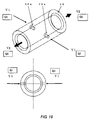
- the explanation describes the relationship between the diameter of a micro-nano bubble discharging port to be provided on the end of a hollow cylinder and the diameter of the hollow cylinder at its part where a through-hole is arranged in the circumferential direction.
- FIG. 18A illustrates a liquid-collision nozzle having two holes 54a.
- D1 the diameter of the part (the part in which the small through-hole is made) against which the jet of liquid collides
- D2 the diameter of a discharging port
- a liquid-collision nozzle illustrated in FIG. 18B has two holes 55a.
- D3 the diameter of the part against which the jet of liquid collides
- D4 the diameter of a discharging port
- either of the nozzles having the structure illustrated in FIG. 18 may be used.
- the nozzle cylinder shown in FIG. 18A has such a structure that the diameter of the discharging port is smaller than the diameter of the collision occurring part of the nozzle cylinder; therefore, the pressure of the dissolved liquid in the vicinity of the spout becomes high. Because of that, even though there is an advantageous effect for miniaturization of micro-nano bubble particles, the bubble generation is a little bit impeded. As a consequence to this, the lowering of the amount of generated bubbles, or the late-generating of bubbles at a place away from the spout, may occur. In contrast to this, the nozzle having the structure illustrated in FIG.
- the nozzle illustrated in FIG. 18B is suitable.
- FIGS. 19 to 21 the relationship between the diameter of the liquid-collision nozzle and micro-nano bubbles is explained referring to FIGS. 19 to 21 , wherein the pressure is kept constant and pure water, which includes 50 ppm of ozone, is used as the dissolved liquid.
- FIG. 19 illustrates the relationship between the flow rate of the jet squirted from the small through-hole of a nozzle 56 and the flow rate of the discharge issued from the discharge port.
- the dissolved liquid squirted from a small through-hole 56a at a speed V1 after its squirting from a single-hole 56a at a liquid rate Q1 per second, collides to generate micro-nano bubbles. Then, it goes out from the discharge port of the nozzle 56 at a speed V2 with a liquid rate Q2 per second.
- the flow rates Q1 and Q2 are same.
- FIG. 20 shows the relationship between the diameter of the small through-hole of the liquid-collision nozzle and the amount of generation of micro-nano bubbles.
- the amount of generated micro-nano bubbles is plotted in the number of bubbles generated per unit volume of the dissolved liquid.
- the diameter of the small through-hole of the liquid-collision nozzle is an important factor that determines the performance of the micro-nano bubbles. Although there is a difference in behavior depending on the nature of the liquid and the gas to be dissolved, the tendency is as described in the above. Therefore, the amount of micro-nano bubbles can be controlled by adjusting the diameter of the small through-hole of the liquid-collision nozzle.
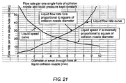
- FIG. 21 shows the relationship between the diameter of the small through-hole of the liquid-collision nozzle and the flow rate Q.
- the flow rate Q is proportional to the square of the diameter of the small through-hole of the liquid-collision nozzle, but the liquid speed V is inversely proportional to the square of the diameter of the liquid-collision nozzle.
- the relationship between the diameter of one single-hole of the small through-hole of the liquid-collision nozzle and the flow rate Q is as shown in FIG. 20 .
- the optimization of the diameter of the small through-hole of the nozzle is possible by determining the number of holes of the liquid-collision nozzles in view of the required flow rate.
- the small through-hole of the nozzle should have a diameter of 0.1 to 6.0 mm. If the diameter of the small through-hole of the nozzle is smaller than 0.1 mm, the amount of generation of small-size bubbles of about 60 ⁇ m or smaller in particle diameter increases. However, the amounts of generation of bubbles having larger diameters than that particle diameter decreases sharply; then, micro-nano bubbles are hardly generated. In addition, if the diameter of the small through-hole of the nozzle is in excess of 6 mm, the total amount of generated bubbles increases.
- the amount of generation of small-size bubbles of about 60 ⁇ m or smaller in particle diameter decreases sharply to 500 bubbles per mL or less; thus, it is not possible to achieve a sufficient effect of the present invention.
- the diameter of the small through-hole of the liquid-collision nozzle should be configured within a range of 0.1 to 3 mm to generate micro-nano bubbles in a large amount of 1000 bubbles per mL or more.
- Micro-nano bubbles were generated using distilled water as the dissolved liquid with the apparatus for generating micro-nano bubbles by the present invention as illustrated in FIGS. 1 and 2 .
- the nozzle used had the same structure as illustrated in FIGS. 3 and 4 , and the nozzle parts 3b and 4b were given a straight shape of a small through-hole of 0.5 mm in diameter.
- micro-nano bubbles were generated by the conventional gas-liquid two-phase swirl flow method using, similarly to the above, distilled water as the dissolved liquid.
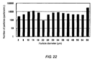
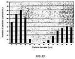
- FIGS. 22 and 23 show the relationship between the amount of generated bubbles and the particle diameter of bubbles.
- FIG. 22 shows the amount generated by the method for generating micro-nano bubbles by the present invention and FIG. 23 shows the same using the gas-flow two-phase swirl flow method.
- the amount of generated bubbles is indicated in the number of bubbles per unit volume of the distilled water (bubble/mL).
- the amount of generated bubbles and their particle diameter are determined using a submerged particle counter at room temperature.
- FIGS. 22 and 23 do not show the amount of bubbles having particle diameters in the nano region; this is because of the difficulty in measuring the number of particles in the nano region with an optical method.
- the present invention can be considered to be a method that generates a large number of bubbles in the sub-micron region, i.e., even in the nano region.
- a use of the apparatus for generating micro-nano bubbles by the present invention for the washing semiconductor wafers and the sterilization of food such as vegetables actually has confirmed that the effect of washing or sterilization continued even when the dissolved liquid became an apparent-clear solution over time, like a bubble-disappeared liquid.
- the present invention gains an effect of being able to continue rendering a washing and sterilization effect by generating micro-nano bubbles, for a long time more than the conventional method would provide. It is understood that the existence of nano-bubbles, which is large in amount, having smaller diameter of less than 1 ⁇ m has produced such an effect.
- the method for generating micro-nano bubbles by the present invention generates micro-nano bubbles using the water hammering power. Therefore, the method is able to generate micro-nano bubbles in a large amount using pure water only without use of substances which are not necessarily needed such as nucleating agents. Accordingly, the method can realize a clean washing and sterilization. Since this water hammering power is maximized by the use of a bubble generating nozzle having an optimized structure and shape and by an apparatus that is able to stably perform the generation of a large amount of bubbles, the application of such combination makes it possible to perform continuous and stable generation of bubbles in an efficient manner. Thereby, the amount of generation of small-size bubbles, not only of the size of micrometer order but also of nanometer order, can be increased together. This feature enhances the capability and function in the washing and sterilizing more than those in conventional technique.
- the apparatus for generating micro-nano bubbles by the present invention is applicable to the clean washing for such as semiconductor wafers.
- the washing of semiconductor wafers has used processing with such as strong acid treatment, alkaline neutralization, and pure water rinsing.
- the process therefore has been complicated and the environmental load has been large because, for example, the process uses drug solutions.
- the present invention is able to solve this problem. Further, the process burden such as in the disposal of drug solutions is eliminated and the required scale for semiconductor manufacturing equipment becomes small and related process is made compact; these are a great industrial value.
- micro-nano bubble-generated liquid other than pure water
- the micro-nano bubble-generated liquid for such use is prepared by adding a gas having excellent oxidizing ability like oxygen or a permeable impurity removal agent such as carbon dioxide or nitrogen gas, and then followed by the micro-nano bubble generation process by the present invention.
- a gas having excellent oxidizing ability like oxygen or a permeable impurity removal agent such as carbon dioxide or nitrogen gas
- micro-nano bubble generating system by the present invention is applicable to medical use, because the system uses micro-nano bubbles generated by a clean system that uses pumps and wetted part made of fluorine resin. Therefore, it is expected that the field of the application of the invented system will expand greatly.
- micro-nano bubbles that uses oxygen or ozone as its constitution gas
- the application range may expand to the fields such as agriculture and the fishery; and the method for generating micro-nano bubbles, the bubble generating nozzle, and the apparatus for generating micro-nano bubbles by the present invention have a very high superiority in such field expansion movement.
Landscapes
- Chemical & Material Sciences (AREA)
- Chemical Kinetics & Catalysis (AREA)
- Engineering & Computer Science (AREA)
- Organic Chemistry (AREA)
- Life Sciences & Earth Sciences (AREA)
- Hydrology & Water Resources (AREA)
- Environmental & Geological Engineering (AREA)
- Water Supply & Treatment (AREA)
- Dispersion Chemistry (AREA)
- Nanotechnology (AREA)
- Health & Medical Sciences (AREA)
- Textile Engineering (AREA)
- Mechanical Engineering (AREA)
- Epidemiology (AREA)
- Animal Behavior & Ethology (AREA)
- General Health & Medical Sciences (AREA)
- Public Health (AREA)
- Veterinary Medicine (AREA)
Abstract
Description
- The present invention relates to a method for, a bubble generating nozzle for, and an apparatus for generating micro-nano bubbles, wherein the method, the nozzle, and the apparatus use water hammering.
- Washing or sterilizing by micro-nano bubbles is a method that uses only water, air, and additives of a trace quantity, offering a reduced environmental load. Due to this, such method have attracted attention as an alternative to a conventional method for washing or sterilizing that uses materials like detergents and chemicals. In addition, because of such method being highly safe, application as a sterilization method for vegetables and foods has been studied. Conventional methods for generating micro-nano bubbles have been known in three fashions: the gas-liquid two-phase swirl flow method, the venturi tube method, and the pressure dissolution method. (For example, refer to
Patent Literatures - Such conventional methods are however not satisfactory because the number of micro-nano bubbles generated by each of such methods is still not large enough. Although each of such conventional three methods can easily produce micro-bubble water, nucleating agent like base and magnesium must be added to the micro-nano water for generating a sufficient number of micro-nano bubbles. Addition of a nucleating agent has been a major obstacle in expansion of application to washing and sterilization of such as semiconductor devices and food. At present however, it is very difficult to generate a large amount of micro-nano bubbles using pure water.
- Pumps of various types are employable as the driving pump in an apparatus that generates bubbles using water, air, and additives of a trace quantity. However, washing and sterilization of semiconductor devices and food require that all the pertinent apparatus components including the driving pump should operate without causing metal contamination. For example, when devices such as semiconductor wafers are to be washed without metal contaminations, all the wetted parts of pumps to be used in an apparatus for generating micro-nano bubbles should be made of those which do not generate any metal ions; and further, such pumps must operate stably at a discharge pressure of 0.3 to 0.6 MPa.
- In consideration for these, the inventors of the present invention have proposed an apparatus that employs a compressed-air driven bellows-cylinder pump as a pump that feeds liquid without using rotating movements (
Patent Literatures 3 and 4). All the wetted parts of the proposed pump are made of fluorine resin to avoid the feared metal contamination that will occur in a rotating type pump. To achieve the goal of performing a clean washing without the influence of contamination, technical development is desired on application of plastic by use of such as fluorine resin to all the related constituent units for generating micro-bubbles, including not only pumps but also nozzles. -
- {Patent Literature 1}
Laid-open patent applicationTOKKAI 2009-274045 - {Patent Literature 2}
Laid-open patent applicationTOKKAI 2008-264771 - {Patent Literature 3}
Patent No.4547451 - {Patent Literature 4}
Patent No.4924907 - In conventional technologies, it is extremely difficult to generate a large amount of micro-nano bubbles only with pure water but without using nucleating agent. Granted that addition of a nucleating agent is intended, the agent is required to be used in a significantly reduced amount. In addition, if micro-nano bubbles can be generated in an amount considerably larger than a quantity that conventional technologies will generate, great improvement in washing and sterilization can be expected and, further, the broadening of application of such technique to various usages becomes practicable. Thus, a method for generating micro-nano bubbles by a new technique instead of prior arts and an apparatus for generating micro-nano bubbles capable of actualizing such new technique have been strongly desired.
- In the technical field to which the present invention relates, constructing a system capable of generating micro-nano bubbles without metal contamination is still being sought as in the past. As stated above, a prospect that this problem can be solved by employing a compressed-air driven bellows-cylinder pump, in which all the wetted parts thereof are made of fluorine resin, is obtained. Moreover, if micro-nano bubbles can be generated in an amount considerably larger than a conventional quantity using a micro-nano bubble generating apparatus that employs the pump of such configuration, it is expected that such bubble-generating method will be a useful washing method as a response to a demand by technical movements toward the fining of wiring in manufacturing semiconductor devices. At present however, a high performance apparatus of metal-free material that can generate increased amount of bubbles has not been available.
- Therefore, it is strongly desired to establish a new method for generating micro-nano bubbles and to develop a high-performance apparatus for generating micro-nano bubbles, by general optimization of structure and shapes of constituents including pumps and other constituting parts such as a bubble generating nozzle, a gas-liquid mixing vessel, and a liquid-feeding device. Ultimately, it is necessary to construct a system capable of generating micro-nano bubbles without metal contamination.
- In view of the background described above, an object of the present invention is to provide an apparatus for generating micro-nano bubbles to construct a system that performs clean washing and sterilizing with large amount of micro-nano bubbles generated using pure water only and can generate micro-nano bubbles without metal contamination. The apparatus intended to be provided, including a bubble generating nozzle and an auto-regulating gas-liquid mixing vessel is to operate on a new method, which is different from conventional arts, for generating micro-nano bubbles using water hammering.
- The basic idea for solving the problem described above is use of violent water hammering to generate a large amount of micro-nano bubbles that contains dissolved gas, wherein the water hammering occurs on collision of water, a non-compressive substance. To actualize this, the inventors of the present invention has been led to the present art through, in the method for generating micro-nano bubbles and the apparatus therefor, optimizing the structure and the shape of the bubble generating nozzle so that the water hammering power will work to its utmost extent and constructing an apparatus for generating micro-nano bubbles having a configuration that accelerates generating large amount of micro-nano bubbles.
- Thus, the configuration of the present invention is as follows:
- (1) The present invention provides a method for generating micro-nano bubbles, wherein the method uses water hammering power that is produced by mutual collision of jets of a solution, which includes dissolved gas, squirted out from each of two or more spouts.
- (2) The present invention provides the method for generating micro-nano bubbles as described in the paragraph (1), wherein the method uses water hammering power to generate micro-nano bubbles, wherein micro-nano bubbles are generated by a mutual collision of jets of a dissolved liquid of a gas-liquid mixture state; the collision of jets is created inside a cylinder that has two or more small through-holes; and the jets of the dissolved liquid are produced by injecting the liquid from the outside of the cylinder via the small through-holes in the cylinder at a pressure higher than the atmospheric pressure.
- (3) The present invention provides the method for generating micro-nano bubbles as described in the paragraph (2), comprising the processes of:
- a sucking process that sucks gas and liquid;
- a pressurization process that pressurizes gas and liquid;
- a dissolved gas enriching process, wherein the pressurized gas-including liquid is mixed with another new gas;
- a dissolved gas miniaturization process that generates micro-nano bubbles,
- wherein a dissolved liquid of a gas-liquid mixture state prepared at the dissolved gas enriching process is injected from the outside of the cylinder having two or more small through-holes, via such small through-holes at a pressure higher than the atmospheric pressure to produce jets of the liquid, and the jets are collided mutually inside the cylinder.
- (4) The present invention provides the method for generating micro-nano bubbles as described in any of the paragraphs (1) to (3), wherein the pressure of being more than the atmospheric pressure at the time of squirting is 0.2 to 0.6 MPa, and the diameter of the small through-holes at the part leading to the hollow of the cylinder is 0.1 to 6.0 mm.
- (5) The present invention provides the method for generating micro-nano bubbles as described in any of the paragraphs (1) to (4), wherein the dissolved liquid is an aqueous solution that includes at least one of substance selected from the group consisting of ozone, oxygen, hydrogen peroxide, chloric acid, perchloric acid, and potassium permanganate.
- (6) The present invention provides the method for generating micro-nano bubbles as described in any of the paragraphs (1) to (4), wherein the dissolved liquid is an aqueous solution that includes a substance selected from the group consisting of carbon dioxide, hydrogen gas, and nitrogen gas.
- (7) The present invention provides a bubble generating nozzle for use in the generating of micro-nano bubbles using water hammering power, comprising:
- a hollow cylinder having two or more small through-holes arrayed in the circumferential direction thereof and
- a micro-nano bubble discharge port provided on at least one end of the hollow cylinder,
- wherein the small through-holes are arranged so that all of their extension lines passing through respective center of the cross-section of each of the small through-holes intersect each other in the inside of the hollow of the cylinder.
- (8) The present invention provides the bubble generating nozzle for generating micro-nano bubbles as described in the paragraph (7), wherein the nozzle has two or more numbers of hollow cylinders.
- (9) The present invention provides the bubble generating nozzle for generating micro-nano bubbles as described in the paragraph (8), wherein the hollow cylinders of two or more numbers are arranged in parallel to or perpendicular to the direction of the inflow or the discharge of the flow of the dissolved liquid.
- (10) The present invention provides the bubble generating nozzle for generating micro-nano bubbles as described in any of the paragraphs (7) to (9), wherein the hollow cylinder has, in its longitudinal direction, a multi-row of two or more rows of small through-holes, and each of such rows consists of two or more small through-holes.
- (11) The present invention provides the bubble generating nozzle for generating micro-nano bubbles as described in any of the paragraphs (7) to (10), wherein the diameter of the small through-hole at the part that leads to the hollow of the hollow cylinder is 0.1 to 6.0 mm.
- (12) The present invention provides the bubble generating nozzle for generating micro-nano bubbles as described in any of the paragraphs (7) to (11), wherein the diameter of the micro-nano bubble discharge port provided on at least one end of the hollow cylinder is equal to or larger than the diameter of a part of the hollow cylinder, wherein such part is such a part where the small through-holes are arranged in a circumferential direction.
- (13) The present invention provides an apparatus for generating micro-nano bubbles, comprising:
- a means for sucking each of gas and liquid;
- a means for pressurizing the gas and the liquid in a lump and transferring them;
- a gas-liquid mixing vessel for enriching the dissolved gas by mixing the transferred liquid, which includes the gas, with another new gas; and
- a means for generating micro-nano bubbles in the gas-liquid mixing vessel using the dissolved liquid of the gas-liquid mixing state, wherein the means has the bubble generating nozzle for generating micro-nano bubbles as described in any of paragraphs (7) to (12).
- (14) The present invention provides the apparatus for generating micro-nano bubbles as described in the paragraph (13), wherein, in the means for generating micro-nano bubbles, the dissolved liquid is squirted at a pressure of 0.2 to 0.6 MPa through the small through-hole of the bubble generating nozzle.
- (15)The present invention provides the apparatus for generating micro-nano bubbles as described in the paragraphs (13) or (14), wherein the gas-liquid mixing vessel has the bubble generating nozzle for generating micro-nano bubbles, and the liquid that includes the gas transferred by the means for pressurizing and transferring is discharged into the gas-liquid mixing vessel by the bubble generating nozzle.
- (16) The present invention provides the apparatus for generating micro-nano bubbles as described in any of the paragraphs (13) to (15), wherein the gas-liquid mixing vessel has a float valve inside or outside the vessel to maintain the volume of the gas and the liquid and the internal pressure inside the vessel always within a prescribed range by discharging excess gas from the vessel.
- (17) The present invention provides the apparatus for generating micro-nano bubbles as described in any of the paragraphs (13) to (16), wherein a pump or piping, or both, through which the gas-liquid mixture liquid flows, is made of plastic.
- (18) The present invention provides the apparatus for generating micro-nano bubbles as described in the paragraph (17), wherein a pump or piping, or both, through which the gas-liquid mixture liquid flows, is made of fluorine resin.
- (19) The present invention provides the apparatus for generating micro-nano bubbles as described in any of the paragraphs (13) to (18), wherein the means for pressurizing and transferring the liquid that includes the gas is an apparatus that uses a compressed-air driven or an electric motor driven bellows cylinder pump.
- (20)The present invention provides the apparatus for generating micro-nano bubbles as described in any of the paragraphs (13) to (19), wherein the dissolved liquid is an aqueous solution that includes at least one of substance selected from the group consisting of ozone, oxygen, hydrogen peroxide, chloric acid, perchloric acid, and potassium permanganate.
- (21)The present invention provides the apparatus for generating micro-nano bubbles as described in any of the paragraphs (13) to (19), wherein the dissolved liquid is an aqueous solution that includes a substance selected from the group consisting of carbon dioxide, hydrogen gas, and nitrogen gas.
- The method for generating micro-nano bubbles by the present invention generates micro-nano bubbles using the water hammering power. Therefore, the method is able to generate micro-nano bubbles in a large amount using pure water only without use of substances which are not necessarily needed such as nucleating agents. Accordingly, the method can realize a clean washing and sterilization. Since this water hammering power is maximized by the use of a bubble-generating nozzle having an optimized structure and shape, the use of such optimized nozzle makes it possible to perform continuous and stable generation of bubbles in an efficient manner. Thereby, the amount of generation of small-size bubbles, not only of the size of micrometer order but also of nanometer order, can be increased together. This feature enhances the capability and function in the washing and sterilizing more than those in conventional technique.
- The apparatus for generating micro-nano bubbles by the present invention has a bubble generating nozzle and equipment configuration that permits the generating of bubbles in a large amount stably; therefore, the apparatus is usable in a set of equipment for clean washing and sterilizing with pure water.
- On the other hand in the gas-liquid mixing vessel that dissolves gas in liquid, transferring gas and liquid in a lump by a pump may sometimes prevent generating uniform micro-nano bubbles. This is because that, if there occurs a phenomenon in which the volume of the gas increases, causing the inside of the gas-liquid mixture vessel to become full of gas and the volume of liquid in the vessel to be lessened, the gas not dissolved in liquid is fed to the bubble generating nozzle in an as-gas-state causing an unstable generation of micro-nano bubbles. This problem is solvable by discharging excess gas from the gas-liquid mixing vessel through a float valve provided inside or outside the vessel. With this float valve, the volume of the gas and the liquid are maintained always within a prescribed range and thereby the amount of generation of the micro-nano bubbles becomes constant.
- Further, for a clean washing that is incompatible with metal ion which a wetted part generates, configuring a pump or piping, or both, in a washing apparatus with plastic or preferably with fluorine resin makes the apparatus become to have high reliability and clean feature.
- The method and the apparatus by the present invention contribute to constructing a micro-nano bubble generating system that generates bubbles without metal contaminations. For example, application of the present invention to washing such as semiconductor wafers simplifies such washing process compared to conventional processes that perform complicated washing using such as drug solutions. Further, the invention is cable of reducing environmental load because the invented method does not need use of material such as drug solutions. Moreover, the use of the invention for sterilization of foods such as vegetables makes it possible to perform reliable and safe sterilization.
-
-
FIG. 1 is a front view of a micro-nano bubble generation system to which the present invention is applied. -
FIG. 2 is a perspective view of the micro-nano bubble generation system to which the present invention is applied. -
FIG. 3 is a cross sectional view of a micro-nano bubble generating nozzle. -
FIG. 4 is a front view of the micro-nano bubble generating nozzle. -
FIG. 5 is a side view of the micro-nano bubble generating nozzle. -
FIG. 6 illustrates a high-speed jet liquid squirting nozzle part. -
FIG. 7 is an enlarged partial cross sectional view of the high-speed jet liquid squirting nozzle part. -
FIG. 8 is a cross sectional view of a nozzle that generates micro-nano bubbles. -
FIG. 9 is a cross sectional detail view of a liquid-collision nozzle with which micro-nano bubbles are generated. -
FIG. 10 is a front view, a cross sectional view, and a three-dimensional view of the liquid-collision nozzle. -
FIG. 11 illustrates a liquid-collision nozzle having multi-row of groups of liquid squirting holes. -
FIG. 12 is a cross sectional view of a gas-liquid mixing vessel. -
FIG. 13 is a detail view of structure of a high-efficiency gas-liquid injection pipe for mixing gas and liquid in the gas-liquid mixing vessel. -
FIG. 14 is a cross sectional view of a float part to be equipped on the gas-liquid mixing vessel. -
FIG. 15 is a cross sectional view of the gas-liquid mixing vessel having a bubble generating nozzle by the present invention. -
FIG. 16 is a cross sectional view of a multi-row nozzle of another configuration that generates micro-nano bubbles. -
FIGS. 17A to 17E are a perspective view and a cross sectional view of the structures of the liquid-collision nozzles by the present invention. -
FIGS. 18A and 18B are a perspective view and a cross sectional view of the structures and shapes of the nozzle cylinders by the present invention. -
FIG. 19 is an illustration that shows the relationship between the flow rate of the jet squirted from the small through-hole of the liquid-collision nozzle and the flow rate of the discharge from the discharge port. -
FIG. 20 is a graph that shows schematically the relationship between the diameter of the small through-hole of the liquid-collision nozzle and the number of bubbles per unit volume. -
FIG. 21 is a graph that shows the relationship between the diameter of the small through-hole of the liquid-collision nozzle and the flow rate Q at the nozzle. -
FIG. 22 is a graph that shows the amount of bubbles generated by the method for generating micro-nano bubbles by the present invention and the particle diameter of the generated bubbles. -
FIG. 23 is a graph that shows the amount of bubbles generated by a conventional gas-liquid two-phase swirl flow method and the particle diameter of the generated bubbles. - The following describes the best mode for carrying out the present invention, referring to drawings.
-
FIG. 1 is a front view of the micro-nano bubble generating system to which the present invention is applied andFIG. 2 is a perspective view of the same. Each of the reference numerals therein denotes;
15: a bellows cylinder pump,
13: a pump controller,
14: a gas-liquid mixing vessel,
12: a pressure sensor,
11: a micro-nano bubble generating nozzle attachment part,
17: a liquid sucking pipe,
16: a gas sucking port, and
18: a gas sucking regulating valve. - These constituents are arranged as illustrated in a perspective view
FIG. 2 . The bellows cylinder pump 15, wetted parts of which are made of fluorine resin, sucks gas and liquid into the pump in a mixture state through theliquid sucking pipe 17 and the gas sucking regulatingvalve 18, with the volume of the gas regulated. The sucked liquid and gas mixture is agitated and compressed inside the bellows to dissolve the gas in the liquid. In the present invention, if the bellows cylinder pump 15 has a metal free structure, such configuration is enough. Any plastic other than fluorine resin can also be useable. Usable plastic includes at least one of plastics selected from the group consisting of, for example: general purpose plastics such as polyethylene, polypropylene, and polyethylene terephthalate; engineering plastics such as polyacetar, polyamide, polycarbonate, and denaturing polyphenylene ether; and super engineering plastics such as polyether sulfone, polyphenylene sulfide, polyether ether ketone, and liquid crystal polymer. When use of plastic is intended, applying above stated various plastics including fluorine resin to the wetted part, not only to the pump only, will provide an apparatus for generating micro-nano bubbles having a high reliability and cleanliness. In addition to the above, when washing or sterilizing in a strict metal free condition is not required, metals and ceramics may be used as well as those plastics mentioned above. - Next, the gas and the liquid are agitated by the pump 15 and are force-fed to the gas-
liquid mixing vessel 14. The pump 15 used is mainly a bellows cylinder pump of compressed-air driven type but an electric motor driven type may be used. The gas and the liquid in the gas-liquid mixing vessel 14 are under the pressure generated by the pump 15; therefore, the gas is easily dissolved. The pressure that force-feeds the gas and the liquid from the pump 15 is watched by thepressure sensor 12. Increasing the quantity of the dissolved gas with this manner, the preparations are made for increasing the amount of generation of the micro-nano bubbles. In the micro-nano bubble generating system by the present invention, it is a practical manner to use a bellows cylinder pump as the pump 15. Depending on the use purpose however, conventional known pumps are applicable. The applicable pumps include a reciprocating pump such as a piston pump, a plunger pump, or a diaphragm pump; or a rotary pump such as a gear pump, an eccentric pump, or a screw pump. - The liquid entered under force-feeding the gas-
liquid mixing vessel 14 mixes with gas to dissolve the gas thereinto and then is transferred to the micro-nano bubble generating nozzle attachment part 11. The micro-nano bubble generating nozzle attachment part 11 is a part to which a nozzle connects, wherein the nozzle generates, from the gas-dissolved liquid, micro-nano bubbles in a large amount having a diameter of 60 µm or smaller, preferably to be 15 µm or smaller. - At that time, the
pressure sensor 12 senses variation of the liquid pressure at the section between the micro-nano bubble generating nozzle attachment part 11 and the gas-liquid mixing vessel 14 to watch the dissolving conditions of the gas-liquid. By this, a constant pressure condition needed for stable generation of micro-nano bubbles is actualized. - The process to be performed by the apparatus for generating micro-nano bubbles to which the present invention is applied is as follows. Treatments that the gas sucking port 16, the
liquid sucking pipe 17, and the gas sucking regulatingvalve 18 perform are the gas- and liquid-sucking process. The pressure is regulated by thepressure sensor 12. Next, the gas-including liquid is pressurized using the bellows cylinder pump 15; this treatment is the gas-liquid pressurization process. Following this process, the pressurized gas-including liquid is mixed with another new gas using thepump controller 13 and the gas-liquid mixing vessel 14; this treatment is the dissolved gas enriching process. After this, the bubble generating nozzle by the present invention, which nozzle will be mentioned later, is connected to the micro-nano bubble generating nozzle attachment part 11 to generate micro-nano bubbles. This process is referred to as the dissolved liquid miniaturization process, in which the micro-nano bubbles are generated by injecting the dissolved liquid from the outside of a cylinder, which has two or more small through-holes, via such small through-holes at a pressure higher than the atmospheric pressure to produce jets of the liquid, and the jets are collided mutually at one point inside the cylinder. - Next, explanation follows to describe a method for generating micro-nano bubbles in a large amount from the dissolved liquid that is in a gas-dissolved state.
FIG. 3 is a cross sectional view of the micro-nano bubble generating nozzle including an attachment part. In the figure,reference numerals bolt 8 and anut 9, wherein the dissolved liquid force-fed by the pump is divided into two streams and each of the streams is separately introduced into theouter cases nozzle parts -
FIG. 4 illustrates the nozzle in the fabricated state, in which thebolt 8 is tightening-fastened by thenut 9. The water that produced micro-nano bubble is discharged in the radial direction indicated by arrows.FIG. 5 is a side view of the micro-nano bubble generating nozzle by high-speed liquid jet squirting, in which the micro-nano bubble water is discharged in the circumferential direction. - The following explains how to generate the micro-nano bubbles using the water stream squirted from the high-speed liquid jet squirting nozzle. The gas-dissolved liquid is discharged from the high-speed liquid jet squirting nozzle at the discharge pressure of 0.2 MPa to 0.6 MPa given by the high-pressure pump 15. The discharged liquid rapidly releases its pressure and collides violently each other producing a water hammering power. The explosive water hammering smashes the gas-dissolve liquid and makes the liquid to be in a state that a large amount of micro-nano bubbles is involved therein. It should be noted that, depending on the method of release, there is a case where the amount of generation of micro-nano bubbles becomes reduced. However, the micro-nano bubbles can be generated in a large amount with the method and the apparatus by the present invention.
-
FIG. 6 is a cross sectional view taken along the line B-B and an outline view of the high-speed liquid jet squirtingnozzle parts nozzle parts pin 5, which defines the center, and positioned guided by the positioning pins 6 and 7, and then fixed. The high-speed liquid jet squirtingnozzle parts -
FIG. 7 is an enlarged cross sectional view of the high-speed liquid jet squirtingnozzle parts FIG. 6 . Since theseparts reference numerals hole flow passages hole flow passages Nozzle parts nozzle parts - The reason of feeding the liquid at a high-pressure is to increase the speed of the liquid in squirting from the small-hole. This means that making the liquid collision high-speed increases the impact energy and that a large amount of micro-nano bubbles of more minute size can be generated thereby.
- Assume that F is the power of collision. Also assume that the density of a liquid is p, the size of a small-hole S, and the velocity of a liquid V. Then, the relationship of F = ρSV2 holds. For the optimal value of F, the optimum design that considers the relation between the size of hole S and the velocity V is needed.
- What is important here is that, if a pump capable of generating a higher pressure is used, there is a possibility that further-large amount of micro-nano bubbles can be generated. For example, it is available to use a high-pressure pump that generates pressures of 0.5 to 250 MPa or so. If a pump of this kind is used, the liquid velocity V increases proportionally to the pressure and the amount of generation of micro-nano bubbles greatly increases because the impact power of the water hammering power F increases with the square of V. However, for the application of such high-pressure pump to an apparatus for generating micro-nano bubbles, it is difficult to meet various demands such as light weight, small size, metal-free, and low maintenance cost.
- In the present invention, by using the nozzle having a structure as illustrated in
FIGS. 3 to 7 , the amount of generation of micro-nano bubbles can be made equal to or more than the conventional quantity when the pressure of squirting the dissolved liquid of the gas-liquid mixing state is the atmospheric pressure (about 0.1 MPa) or more. Further, setting the pressure to 0.2 MPa or higher makes it possible to generate micro-nano bubbles in an amount sufficient for performing clean washing and sterilizing. As mentioned above in the present invention, the lower limit of the squirting pressure of the dissolved liquid can be set to 0.2 MPa, a lower value than the conventional pressure. It therefore becomes practicable to use a pump suitable for eliminating metal contamination, that is, the compressed-air driven or electric-motor driven bellows cylinder pump 15 made of fluorine resin, as shown inFIGS. 1 and2 . On the other hand, if the squirting pressure of the dissolved liquid exceeds 0.6 MPa while using the compressed-air driven or electric-motor driven bellows cylinder pump of the present invention, the amount of generation of micro-nano bubbles tends to be saturated. Therefore, the squirting pressure of the dissolved liquid in the present invention is preferred to be 0.2 to 0.6 MPa. - The micro-nano bubble generating nozzle by the present invention needs to have a diameter of 0.1 to 6 mm at its
nozzle parts FIG. 7 so as to squirt the jet of the dissolved liquid in a pressure higher than the atmospheric pressure, preferably 0.2 to 0.6 MPa, which are lower than conventional pressures. Here, the openings of thenozzle parts nozzle parts nozzle parts - The small-
hole flow passages nozzle parts nozzle parts hole flow passages - An example of another method for colliding the gas-dissolved liquid will be explained referring to
FIG. 8 . Illustrated inFIG. 8 is the nozzle for generating micro-nano bubbles, which is comprised of anozzle case 21, a micro-nanobubble discharging nozzle 22, and a base 24, wherein one or more liquid-collision nozzles 23 are installed on the base 24. -
FIG. 9 is an enlarged view of the part where the liquid-collision nozzle 23 shown inFIG. 8 is disposed.FIG. 10 illustrates the shape of a single piece of the liquid-collision nozzle 23. A small-hole 23a opens toward the center of the liquid-collision nozzle 23. High-pressure liquid entering through this small-hole at a high-pressure in the direction of the arrow Q collides in the center of the liquid-collision nozzle 23, generating micro-nano bubbles. - The experiment told that controlling the velocity of liquid V made the amount of generated micro-nano bubbles increased and prolonged the life of bubbles. When the velocity V exceeds 25 m/s as a guideline, the nozzle generates micro-nano bubbles stably.
- The same effect will be obtained at a lower liquid velocity by squirting the liquid toward center from every direction concentrating the water hammering at the center. This means that when water hammering is given from every direction, the same or more effect will be produced even if the velocity is reduced to 1/2. For example, since F = 2ρSV2, when eight holes are arranged so that the hammering among the jets concentrates in the center, the force at the center becomes F = ρS(1/2)2 x 8 = 2ρSV2. Thus, when the small-hole of the nozzle is provided in a plural number for concentrating the water hammering produced by the liquid collision, the energy of the liquid collision becomes same even if the velocity V is low because the flowing quantity of liquid increases. Since the amount of generation of micro-nano bubbles will be acceptably same if the energy in the collisions of the liquid are same, the pressure of discharging the liquid can be lowered and the amount of generation of micro-nano bubbles will be secured as desired.
-
FIG. 10 illustrates the shape of the liquid-collision nozzles 23, wherein a small-hole 23a is made in the circumference of the nozzle-cylinder part of the liquid-collision nozzle 23. Through this small-hole, the dissolved liquid squirts to collide in the center and generates micro-nano bubbles. The micro-nano bubbles thus generated is discharged toward the arrow Q. When a plurality of the liquid-collision nozzle 23 is gather-arrayed, a large amount of micro-nano bubbles are generated and are discharged from a nozzle part 22a of the dischargingnozzle 22 illustrated inFIG. 8 . As illustrated inFIG. 11 , the shape of a liquid-collision nozzle 25 is such a shape as has small-holes 25a in a multi-row configuration. For example therefore, when three places are provided for producing the water hammering by making holes in a three-row configuration, it becomes practicable to generate micro-nano bubbles in a large amount. Thus, this practice is a useful method for miniaturization and increased efficiency. - Discharging the liquid from a plurality of holes, as the nozzle illustrated in
FIG. 11 , increases the intensity of the water hammering. Using this technique will not decrease the amount of generation of micro-nano bubbles even if the velocity V is low; and consequently a pump with a high discharging pressure is not needed, which imposes less defrayment. Thus, this technique is industrially very useful and permits development of a nozzle having good efficiency. -
FIG. 12 is a cross sectional view of the gas-liquid mixing vessel 14.FIG. 13 is an enlarged view of the circled area E inFIG. 12 . In a conventional gas-liquid mixing vessel, wherein gas and liquid are mixed under a high pressure, the mixture of gas and pure water is fed into the gas-liquid mixing vessel by a pump and spouted therein upward like a water spout to merge the mixture. This method however is not efficient in mixing; therefore it is necessary to generate micro-nano bubbles in an increased amount for improved efficiency. - Then, as illustrated in
FIG. 12 , gas and liquid are fed by a pump in the direction of the arrow A toward the arrow B and are introduced into gas-liquid injection pipes FIG. 13 illustrates, water hammering produced by colliding liquid in the directions from the arrow X and the arrow Y is used for increased efficiency of the mixing of the gas and liquid discharged from a hole of gas-liquid injection pipe 32a and a hole of gas-liquid injection pipe 33a of the gas-liquid injection pipe 33. Thereby, mixing gas and liquid is performed efficiently and gas-liquid mixture liquid as a raw material of micro-nano bubbles is produced speedily with increased merging rate. - A
float 31 illustrated inFIG. 12 is provided for the purpose of exhausting excessively entered gas to outside if gas enters excessively in mixing gas and liquid. Thefloat 31 exhausts entered excess gas safely and regulates the amount of gas and liquid to a proper level. This means that a certain situation is produced as described below. If there remains undissolved gas due to the entering of excessive amount of gas, the gas will flow into the nozzle and impedes the generation of micro-nano bubbles. The float eliminates this adverse effect of impeding bubble generation and controls the amount of generation of the micro-nano bubbles to a proper level, enabling sending bubbles stably. -
FIG. 14 illustrates a cross sectional view of a part of thefloat 31 shown inFIG. 12 . The structure of thefloat pipe 31 comprises a float tip part 31a (which is tapered toward its end), a reinforcing rib 31b for prevention of collapse by the pressure of liquid, and astop plug 31c. - Mixing gas and liquid requires its method to increase the dissolving efficiency of gas into liquid by enlarging the contact area of gas and liquid. If the efficiency lowers, shortage of the generation amount occurs due to a shortage of gas, which is a fatal problem in the generating of micro-nano bubbles.
- We examined how much the amount of generated micro-nano bubbles will be increased depending on the degree of control over the amount of gas and liquid. As a result, it was understood that the following are the points. If the amount of liquid in the volume ratio inside the gas-liquid mixing vessel occupies 60% and the amount of gas occupies 40%, the gas-liquid ratio is the ideal balance of amounts. To stabilize the amount of generation of the micro-nano bubbles and to increase the amount of generated bubbles, it is necessary that the condition of the mixing of gas to be dissolved and liquid should be optimized by exhausting the excess gas from an excess
gas exhausting port 48 of a float socket 47 using the buoyancy of thefloat 31 caused by the liquid for controlling their ratio automatically. In the present invention, for the purpose of increasing greatly the amount of generation of micro-nano bubbles, it is preferable to control the volume ratio of gas and liquid in the gas-liquid mixing vessel within the range of gas to liquid ratio = 50 : 50 to 5 : 95 so that liquid will occupy more part in the volume ratio. Also in the present invention, thefloat 31 may be installed outside the gas-liquid mixing vessel, instead of installing inside. In this arrangement, connecting the inside and outside of the gas-liquid mixing vessel using such as a communication pipe permits controlling the volume ratio of gas and liquid. -
FIG. 15 is an example of a gas-liquid mixing vessel that has more improved efficiency. The fundamental working is same as those illustrated inFIGS. 12 and13 . This vessel is a gas-liquid mixing vessel structured based on a gas-liquid mixing vessel comprising a gas-liquid mixing vesselouter frame 36, a micro-nanobubble generating nozzle 38, and amember 40, wherein a structure resistible to the internal pressure of the gas-liquid mixing vessel is given to the basic structure. The mixing of gas and liquid is efficiently performed inside that vessel. - In
FIG. 15 , each of the reference numerals denotes: - 36: the gas-liquid mixing vessel outer frame;
- 41: a float;
- 35: a float holder;
- 35a: an excess gas exhausting port on float holder; and
- 41a: a float tip, wherein the float tip 41a has a function that regulates automatically the excess gas.
- When using an conventional apparatus that generates a less amount of micro-nano bubbles, a major method for generating an increased amount of micro-nano bubbles is as follows. The method is comprised of processes of: generating micro-nano bubbles once in a water tank; pumping up micro-nano bubbles generated in the water tank again; injecting additional gas to be dissolved into the pumped bubble-containing liquid at the gas-liquid mixing vessel; and circulating the gas-injected bubble-containing liquid multiple times to bring the bubble-containing liquid to a state in which a large amount of micro-nano bubbles are involved. Thereby, micro-nano bubbles are generated in an increased amount.
- In this method, it is difficult to control the amount of generation of the micro-nano bubbles. Further, circulating technique invites a trouble such as occurrence of contamination. Because of that, an apparatus that is capable of generating a large amount of micro-nano bubbles in one process without use of circulation technique is desired.
- Therefore, it is intended to generate micro-nano bubbles, without circulation in the gas-liquid mixing vessel to be used in the present invention, by a liquid-collision in the gas-liquid mixture state under the working of the micro-nano
bubble generating nozzle 38, which is held on anozzle holder 39, having a structure same as illustrated inFIG. 8 . - In this situation, it is the requisite condition that the
nozzle 38 arranged inside the gas-liquid mixing vessel should issue the dissolved liquid of the gas-liquid mixture state at a flow rate more than that of the nozzle 11 arranged at the distal end to increase the pressure inside the gas-liquid mixing vessel. If the flow rate of thenozzle 38 is smaller, micro-nano bubbles sometimes may not be generated from the nozzle attached at the distal end. - The effect of the installing of the
nozzle 38 inside the gas-liquid mixing vessel is that one-path of processing along the gas-liquid mixing vessel to the nozzle permits a stable generation of a large amount of micro-nano bubbles. Thereby, such technique enables provision of an apparatus suitable for washing process in semiconductor manufacturing line for example. - In the present invention, configuring gas-liquid mixing vessels in a multi-stage cascade makes it possible to generate a larger amount of micro-nano bubbles; this is a useful means for generating a large amount of bubbles.
-
FIG. 16 offers another method for generating micro-nano bubbles. This method employs an arrangement in which two or more small-hole nozzles 45 are arrayed perpendicular to the incoming or discharging direction (longitudinal direction) of the flow of the dissolved liquid. This array is different from the parallel arrangement illustrated inFIG. 8 . The arrangement illustrated inFIG. 16 has an advantage in that a desired flow rate is easily ensured, because the small-hole nozzles are arrayed as the figure shows with respect to theouter cases nozzle hole 44; and thereby the small-hole nozzles become to have discharging ports on their both sides. - As can be seen in
FIG. 16 , the gas-liquid mixture liquid fed from the port IN is brought into a water hammering state by thenozzle 45 to generate micro-nano bubbles, and then discharged to the both sides of the nozzle. This ensures the flow rate as desired and the efficiency is doubled, therefore the energy needed for generating micro-nano bubbles becomes half. - Bubbles like this produced by a water hammering gives less damage to the nozzle structure, because collision occurs only between the liquid. Therefore, it is possible to make a bubble generating apparatus have a longer service life.
- The significant feature of the method and the apparatus for generating micro-nano bubbles by the present invention is that they are compatible with using pure water as a dissolved liquid that does not include any foreign matters such as nucleating agent in an application to washing and sterilization of semiconductor devices and food. Granted that a use of nucleating agent, or the like, is needed to increase the amount of generation of micro-nano bubbles, the quantity of addition of such material into pure water can be considerably reduced. In the present invention, tap water, well water, or spring water such as natural water other than pure water can be used in consideration of the supply state or usability. Further in the present invention, the strengthening of the oxidizing action of the dissolved liquid and the reformulating of the liquid for enhancing permeability required for impurity removing action may be practicable to increase the effectiveness of the washing and sterilizing.
- The method for strengthening the oxidizing action of the dissolved liquid stated above includes the use of the dissolved liquid which is an aqueous solution prepared by adding, to pure water, at least one of oxidant selected from the group consisting of ozone, oxygen, hydrogen peroxide, chloric acid, perchloric acid, and potassium permanganate. Among these oxidant, ozone and oxygen are preferable oxidant for the present invention, because they have little adverse effect as an additive and their environmental load is very small.
- As the method for enhancing the permeability for impurity removing action in the dissolved liquid stated above, it is a preferable method to add a gas selected from the group consisting of carbon dioxide, hydrogen gas, and nitrogen gas, which has excellent permeability for impurity removing action. On generation of micro-nano bubbles, carbon dioxide, hydrogen gas, or nitrogen gas invades easily the boundary surface between a semiconductor device and impurities, such as residuals of resist, adhering to its surface. Thereby, the effectiveness of the washing is largely increased. Further, since carbon dioxide or nitrogen gas is harmless to human body, such gas is suitable for the present invention as a reformulating additive.
- The structure and shape of the micro-nano bubble generating nozzle by the present invention will be detailed referring to concrete embodiments.
-
FIG. 17 illustrates the structure and shape of the liquid-collision nozzle which was examined to generate micro-nano bubbles using a water hammering power.FIG. 17A illustrates a comparative example to the embodiment of the present invention andFIGS. 17B to 17E illustrate embodiments of the present invention. -
FIG. 17A illustrates a configuration that a single-hole 49a is made in the circumference of a hollow cylinder. In this comparative example, which has the single-hole 49a of one small through-hole, the dissolved liquid squirted at a speed V collides against the wall of apipe 49. Therefore, the amount of generated micro-nano bubbles is not much and there is a disadvantage in that the impact by the collision against the wall may damage the wall. - A liquid-collision nozzle illustrated in
FIG. 17B has a two-hole 50a configured with two small through-holes. In this embodiment, the dissolved liquid squirting at a speed V actualizes a collision at a speed of 2V, because the two-hole 50a provides another spout at the opposite side. Thus, the collision energy becomes higher than that of the comparison example ofFIG. 17A . - A liquid-collision nozzle illustrated in
FIG. 17C has a three-hole 51a configured with three small through-holes. In this embodiment, the dissolved liquid squirts at a speed V from three holes provided at an interval of 120 degree for collision. Thereby, the energy in the center of collision of the liquid squirted at a speed V becomes three times. This means that, when the collision is produced using three spouts and when the collision energy same as the one in the former two-hole case is considered to be enough, the collision produces still the same amount of energy even if the speed V is reduced by as much as 20%. Since the pump pressure determines the speed V, even a lowered pump pressure is still capable of generating micro-nano bubbles. - A liquid-collision nozzle illustrated in
FIG. 17D has a four-hole 52a configured with four small through-holes. In this embodiment, the dissolved liquid squirts at a speed V from four holes provided at an interval of 90 degree for collision. Thereby, the energy in the center of collision of the liquid squirted at a speed V becomes four times. This means that, when the collision is produced using four spouts and when the collision energy same as the one in the former two-hole case is considered to be enough, the collision produces still the same amount of energy even if the speed V is reduced by as much as 30%. Since the pump pressure determines the speed V, even a lowered pump pressure is still capable of generating micro-nano bubbles. - A liquid-collision nozzle illustrated in
FIG. 17E has a five-hole 53a configured with five small through-holes. In this embodiment, the dissolved liquid squirts at a speed V from five holes provided at an interval of 72 degree for collision. Thereby, the energy in the center of collision of the liquid squirted at a speed V becomes five times. This means that, when the collision is produced using five spouts and when the collision energy same as the one in the former two-hole case is considered to be enough, the collision produces still the same amount of energy even if the speed V is reduced by as much as 40%. Since the pump pressure determines the speed V, even a lowered pump pressure is still capable of generating micro-nano bubbles. - As stated above, micro-nano bubbles, which were not generated without a high-pressure pump, can be generated in a large amount by optimizing the structure and arrangement of the through-hole of the liquid-collision nozzle even if the pump pressure is 0.2 MPa; thus this technique is able to actualize energy-saving.
- Referring to
FIG. 18 , the following explains a diameter-related feature in the liquid-collision nozzle by the present invention that generates micro-nano bubble. The explanation describes the relationship between the diameter of a micro-nano bubble discharging port to be provided on the end of a hollow cylinder and the diameter of the hollow cylinder at its part where a through-hole is arranged in the circumferential direction. -
FIG. 18A illustrates a liquid-collision nozzle having two holes 54a. In a nozzle cylinder 54, the diameter of the part (the part in which the small through-hole is made) against which the jet of liquid collides is made large, referred to as D1, and the diameter of a discharging port is made small, referred to as D2. With this configuration, pressure is immediately imposed on micro-nano bubbles generated by the collision. Thereby, the composition of micro-nano bubbles can be controlled. That is, this diameter configuration works as a means for controlling the distribution of particles in micro-nano bubbles and therefore an advantageous effect is brought in the miniaturization of particles. - A liquid-collision nozzle illustrated in
FIG. 18B has two holes 55a. In anozzle cylinder 55, the diameter of the part against which the jet of liquid collides is made small, referred to as D3, and the diameter of a discharging port is made large, referred to as D4. With this configuration, pressure is not imposed on micro-nano bubbles generated by the collision. Therefore, the distribution of particles of micro-nano bubbles which expand on generation becomes a little large. - In the present invention, either of the nozzles having the structure illustrated in
FIG. 18 may be used. The nozzle cylinder shown inFIG. 18A has such a structure that the diameter of the discharging port is smaller than the diameter of the collision occurring part of the nozzle cylinder; therefore, the pressure of the dissolved liquid in the vicinity of the spout becomes high. Because of that, even though there is an advantageous effect for miniaturization of micro-nano bubble particles, the bubble generation is a little bit impeded. As a consequence to this, the lowering of the amount of generated bubbles, or the late-generating of bubbles at a place away from the spout, may occur. In contrast to this, the nozzle having the structure illustrated inFIG. 18B is able to generate a large amount of bubbles stably, because the nozzle allows pressure release at its discharging port. Since it is possible to regulate the miniaturization of micro-nano bubbles by the diameter of the small through-hole of the nozzle, the nozzle illustrated inFIG. 18B is suitable. - Regarding a liquid-collision nozzle illustrated in
FIG. 18B , the relationship between the diameter of the liquid-collision nozzle and micro-nano bubbles is explained referring toFIGS. 19 to 21 , wherein the pressure is kept constant and pure water, which includes 50 ppm of ozone, is used as the dissolved liquid. -
FIG. 19 illustrates the relationship between the flow rate of the jet squirted from the small through-hole of anozzle 56 and the flow rate of the discharge issued from the discharge port. InFIG. 19 , the dissolved liquid squirted from a small through-hole 56a at a speed V1, after its squirting from a single-hole 56a at a liquid rate Q1 per second, collides to generate micro-nano bubbles. Then, it goes out from the discharge port of thenozzle 56 at a speed V2 with a liquid rate Q2 per second. Here, the flow rates Q1 and Q2 are same. -
FIG. 20 shows the relationship between the diameter of the small through-hole of the liquid-collision nozzle and the amount of generation of micro-nano bubbles. In this graph, the amount of generated micro-nano bubbles is plotted in the number of bubbles generated per unit volume of the dissolved liquid. As can be known fromFIG. 20 , when the diameter of the small through-hole of the liquid-collision nozzle becomes larger, V1 reduces and the liquid rate Q1 increases. In this case, the amount of generated micro bubbles (60 µm or larger in diameter) increases but the amount of generated nano bubbles reduces. On the other hand, when the diameter of a liquid-collision nozzle becomes smaller, the liquid rate Q1 reduces. In this case, the amount of generated micro bubbles (60 µm or larger in diameter) reduces and V1 increases, but the amount of generated nano bubbles (2 µm or smaller in diameter) increases. - Thus, the diameter of the small through-hole of the liquid-collision nozzle is an important factor that determines the performance of the micro-nano bubbles. Although there is a difference in behavior depending on the nature of the liquid and the gas to be dissolved, the tendency is as described in the above. Therefore, the amount of micro-nano bubbles can be controlled by adjusting the diameter of the small through-hole of the liquid-collision nozzle.
-
FIG. 21 shows the relationship between the diameter of the small through-hole of the liquid-collision nozzle and the flow rate Q. Where the liquid pressure is kept constant, the flow rate Q is proportional to the square of the diameter of the small through-hole of the liquid-collision nozzle, but the liquid speed V is inversely proportional to the square of the diameter of the liquid-collision nozzle. Thus, the relationship between the diameter of one single-hole of the small through-hole of the liquid-collision nozzle and the flow rate Q is as shown inFIG. 20 . The optimization of the diameter of the small through-hole of the nozzle is possible by determining the number of holes of the liquid-collision nozzles in view of the required flow rate. - As can be known from
FIG. 20 , it is necessary in the present invention that the small through-hole of the nozzle should have a diameter of 0.1 to 6.0 mm. If the diameter of the small through-hole of the nozzle is smaller than 0.1 mm, the amount of generation of small-size bubbles of about 60 µm or smaller in particle diameter increases. However, the amounts of generation of bubbles having larger diameters than that particle diameter decreases sharply; then, micro-nano bubbles are hardly generated. In addition, if the diameter of the small through-hole of the nozzle is in excess of 6 mm, the total amount of generated bubbles increases. On the contrary however, the amount of generation of small-size bubbles of about 60 µm or smaller in particle diameter decreases sharply to 500 bubbles per mL or less; thus, it is not possible to achieve a sufficient effect of the present invention. It is more preferable in the present invention that the diameter of the small through-hole of the liquid-collision nozzle should be configured within a range of 0.1 to 3 mm to generate micro-nano bubbles in a large amount of 1000 bubbles per mL or more. - Micro-nano bubbles were generated using distilled water as the dissolved liquid with the apparatus for generating micro-nano bubbles by the present invention as illustrated in
FIGS. 1 and2 . The nozzle used had the same structure as illustrated inFIGS. 3 and4 , and thenozzle parts FIGS. 22 and23 show the relationship between the amount of generated bubbles and the particle diameter of bubbles.FIG. 22 shows the amount generated by the method for generating micro-nano bubbles by the present invention andFIG. 23 shows the same using the gas-flow two-phase swirl flow method. The amount of generated bubbles is indicated in the number of bubbles per unit volume of the distilled water (bubble/mL). The amount of generated bubbles and their particle diameter are determined using a submerged particle counter at room temperature.FIGS. 22 and23 do not show the amount of bubbles having particle diameters in the nano region; this is because of the difficulty in measuring the number of particles in the nano region with an optical method. - Comparison of the results shown in
FIGS. 22 and23 teaches that the method for generating micro-nano bubbles by the present invention generates larger amount of bubbles compared to the amount generated by the conventional gas-liquid two-phase swirl flow method over the entire particle diameter region of about 60 µm or smaller. Particularly, the difference in the region of the bubble particle diameter of 20 to 40 µm is considerable. In addition, comparison of both methods for the region of the bubble particle diameter of 2 to 10 µm tells that the generated bubbles by the present invention is equal to or slightly larger than that by the conventional method in the amount. By analogy from the results of the number of generated bubbles in the region of a small particle diameter, the present invention can be considered to be a method that generates a large number of bubbles in the sub-micron region, i.e., even in the nano region. A use of the apparatus for generating micro-nano bubbles by the present invention for the washing semiconductor wafers and the sterilization of food such as vegetables actually has confirmed that the effect of washing or sterilization continued even when the dissolved liquid became an apparent-clear solution over time, like a bubble-disappeared liquid. This means that the present invention gains an effect of being able to continue rendering a washing and sterilization effect by generating micro-nano bubbles, for a long time more than the conventional method would provide. It is understood that the existence of nano-bubbles, which is large in amount, having smaller diameter of less than 1µm has produced such an effect. - As stated above, the method for generating micro-nano bubbles by the present invention generates micro-nano bubbles using the water hammering power. Therefore, the method is able to generate micro-nano bubbles in a large amount using pure water only without use of substances which are not necessarily needed such as nucleating agents. Accordingly, the method can realize a clean washing and sterilization. Since this water hammering power is maximized by the use of a bubble generating nozzle having an optimized structure and shape and by an apparatus that is able to stably perform the generation of a large amount of bubbles, the application of such combination makes it possible to perform continuous and stable generation of bubbles in an efficient manner. Thereby, the amount of generation of small-size bubbles, not only of the size of micrometer order but also of nanometer order, can be increased together. This feature enhances the capability and function in the washing and sterilizing more than those in conventional technique.
- Further, for a clean washing that is incompatible with metal ion which a wetted part generates, configuring a pump or piping, or both, in a washing apparatus with plastic or preferably with fluorine resin makes the apparatus become to have high reliability and clean feature. Thus, the apparatus for generating micro-nano bubbles by the present invention is applicable to the clean washing for such as semiconductor wafers. Conventionally, the washing of semiconductor wafers has used processing with such as strong acid treatment, alkaline neutralization, and pure water rinsing. The process therefore has been complicated and the environmental load has been large because, for example, the process uses drug solutions. However, the present invention is able to solve this problem. Further, the process burden such as in the disposal of drug solutions is eliminated and the required scale for semiconductor manufacturing equipment becomes small and related process is made compact; these are a great industrial value.
- Further, in the semiconductor wafer washing, the use of a micro-nano bubble-generated liquid, other than pure water, improves the washing effect largely and makes the washing process very simple with the washing equipment downsized. The micro-nano bubble-generated liquid for such use is prepared by adding a gas having excellent oxidizing ability like oxygen or a permeable impurity removal agent such as carbon dioxide or nitrogen gas, and then followed by the micro-nano bubble generation process by the present invention. Thereby, the washing becomes environment friendly. Further, the process burden such as in the disposal of drug solutions is eliminated and the required scale for semiconductor manufacturing equipment becomes small and related process is made compact; these are a great industrial value.
- The micro-nano bubble generating system by the present invention is applicable to medical use, because the system uses micro-nano bubbles generated by a clean system that uses pumps and wetted part made of fluorine resin. Therefore, it is expected that the field of the application of the invented system will expand greatly.
- Further, the capability of the washing and sterilization by micro-nano bubbles that uses oxygen or ozone as its constitution gas can be applied not only to the semiconductor field but also to fields of foods and vegetables. Thus, there is a possibility in that the application range may expand to the fields such as agriculture and the fishery; and the method for generating micro-nano bubbles, the bubble generating nozzle, and the apparatus for generating micro-nano bubbles by the present invention have a very high superiority in such field expansion movement.
Claims (21)
- A method for generating micro-nano bubbles, wherein the method uses water hammering power that is produced by mutual collision of jets of a solution, which includes dissolved gas, squirted out from each of two or more spouts.
- The method for generating micro-nano bubbles according to claim 1, wherein the method uses water hammering power to generate micro-nano bubbles, wherein micro-nano bubbles are generated by a mutual collision of jets of a dissolved liquid of a gas-liquid mixture state; the collision of jets is created inside a cylinder that has two or more small through-holes; and the jets of the dissolved liquid are produced by injecting the liquid from the outside of the cylinder via the small through-holes in the cylinder at a pressure higher than the atmospheric pressure.
- The method for generating micro-nano bubbles according to claim 2, comprising:a sucking process that sucks gas and liquid;a pressurization process that pressurizes gas and liquid;a dissolved gas enriching process, wherein the pressurized gas-including liquid is mixed with another new gas; anda dissolved gas miniaturization process that generates micro-nano bubbles,wherein a dissolved liquid of a gas-liquid mixture state prepared at the dissolved gas enriching process is injected from the outside of the cylinder having two or more small through-holes, via such small through-holes at a pressure higher than the atmospheric pressure to produce jets of the liquid, and the jets are collided mutually inside the cylinder.
- The method for generating micro-nano bubbles according to any of claims 1 to 3, wherein the pressure of being more than the atmospheric pressure at the time of squirting is 0.2 to 0.6 MPa, and the diameter of the small through-holes at the part leading to the hollow of the cylinder is 0.1 to 6.0 mm.
- The method for generating micro-nano bubbles according to any of claims 1 to 4, wherein the dissolved liquid is an aqueous solution that includes at least one of substance selected from the group consisting of ozone, oxygen, hydrogen peroxide, chloric acid, perchloric acid, and potassium permanganate.
- The method for generating micro-nano bubbles according to any of claims 1 to 4, wherein the dissolved liquid is an aqueous solution that includes a substance selected from the group consisting of carbon dioxide, hydrogen gas, and nitrogen gas.
- A bubble generating nozzle for use in the generating of micro-nano bubbles using water hammering power, comprising:a hollow cylinder having two or more small through-holes arrayed in the circumferential direction thereof anda micro-nano bubble discharge port provided on at least one end of the hollow cylinder,wherein the small through-holes are arranged so that all of their extension lines passing through respective center of the cross-section of each of the small through-holes intersect each other in the inside of the hollow of the cylinder.
- The bubble generating nozzle for generating micro-nano bubbles according to claim 7, wherein the nozzle has two or more numbers of hollow cylinders.
- The bubble generating nozzle for generating micro-nano bubbles according to claim 8, wherein the hollow cylinders of two or more numbers are arranged in parallel to or perpendicular to the direction of the inflow or the discharge of the flow of the dissolved liquid.
- The bubble generating nozzle for generating micro-nano bubbles according to any of claims 7 to 9, wherein the hollow cylinder has, in its longitudinal direction, a multi-row of two or more rows of small through-holes, and each of such rows consists of two or more small through-holes.
- The bubble generating nozzle for generating micro-nano bubbles according to any of claims 7 to 10, wherein the diameter of the small through-hole at the part that leads to the hollow of the hollow cylinder is 0.1 to 6.0 mm.
- The bubble generating nozzle for generating micro-nano bubbles according to any of claims 7 to 11, wherein the diameter of the micro-nano bubble discharge port provided on at least one end of the hollow cylinder is equal to or larger than the diameter of a part of the hollow cylinder, wherein such part is such a part where the small through-holes are arranged in a circumferential direction.
- An apparatus for generating micro-nano bubbles, comprising:a means for sucking each of gas and liquid;a means for pressurizing the gas and the liquid in a lump and transferring them;a gas-liquid mixing vessel for enriching the dissolved gas by mixing the transferred liquid, which includes the gas, with another new gas; anda means for generating micro-nano bubbles in the gas-liquid mixing vessel using the dissolved liquid of the gas-liquid mixing state, wherein the means has the bubble generating nozzle for generating micro-nano bubbles as described in any of claims 7 to 12.
- The apparatus for generating micro-nano bubbles according to claim 13, wherein, in the means for generating micro-nano bubbles, the dissolved liquid is squirted at a pressure of 0.2 to 0.6 MPa through the small through-hole of the bubble generating nozzle.
- The apparatus for generating micro-nano bubbles according to claims 13 or 14, wherein the gas-liquid mixing vessel has the bubble generating nozzle for generating micro-nano bubbles, and the liquid that includes the gas transferred by the means for pressurizing and transferring is discharged into the gas-liquid mixing vessel by the bubble generating nozzle.
- The apparatus for generating micro-nano bubbles according to any of claims 13 to 15, wherein the gas-liquid mixing vessel has a float valve inside or outside the vessel to maintain the volume of the gas and the liquid and the internal pressure inside the vessel always within a prescribed range by discharging excess gas from the vessel.
- The apparatus for generating micro-nano bubbles according to any of claims 13 to 16, wherein a pump or piping, or both, through which the gas-liquid mixture liquid flows, is made of plastic.
- The apparatus for generating micro-nano bubbles according to claim 17, wherein a pump or piping, or both, through which the gas-liquid mixture liquid flows, is made of fluorine resin.
- The apparatus for generating micro-nano bubbles according to any of claims 13 to 18, wherein the means for pressurizing and transferring the liquid that includes the gas is an apparatus that uses a compressed-air driven or an electric motor driven bellows cylinder pump.
- The apparatus for generating micro-nano bubbles according to any of claims 13 to 19, wherein the dissolved liquid is an aqueous solution that includes at least one of substance selected from the group consisting of ozone, oxygen, hydrogen peroxide, chloric acid, perchloric acid, and potassium permanganate.
- The apparatus for generating micro-nano bubbles according to any of claims 13 to 19, wherein the dissolved liquid is an aqueous solution that includes a substance selected from the group consisting of carbon dioxide, hydrogen gas, and nitrogen gas.
Applications Claiming Priority (1)
| Application Number | Priority Date | Filing Date | Title |
|---|---|---|---|
| PCT/JP2013/066902 WO2014199525A1 (en) | 2013-06-13 | 2013-06-13 | Micro and nano bubble generating method, generating nozzle, and generating device |
Publications (3)
| Publication Number | Publication Date |
|---|---|
| EP3009184A1 true EP3009184A1 (en) | 2016-04-20 |
| EP3009184A4 EP3009184A4 (en) | 2016-05-11 |
| EP3009184B1 EP3009184B1 (en) | 2019-05-01 |
Family
ID=52021854
Family Applications (1)
| Application Number | Title | Priority Date | Filing Date |
|---|---|---|---|
| EP13886736.1A Active EP3009184B1 (en) | 2013-06-13 | 2013-06-13 | Method and device for generating micro and nano bubbles |
Country Status (5)
| Country | Link |
|---|---|
| US (1) | US10293309B2 (en) |
| EP (1) | EP3009184B1 (en) |
| KR (3) | KR20160005070A (en) |
| CN (1) | CN105228736B (en) |
| WO (1) | WO2014199525A1 (en) |
Cited By (1)
| Publication number | Priority date | Publication date | Assignee | Title |
|---|---|---|---|---|
| EP3456815A4 (en) * | 2016-05-13 | 2019-11-27 | Sigma-Technology Inc. | AQUEOUS SOLUTION THAT CAN BE ADMINISTERED TO A LIVING BODY AND METHOD FOR ITS PRODUCTION |
Families Citing this family (38)
| Publication number | Priority date | Publication date | Assignee | Title |
|---|---|---|---|---|
| CA2856196C (en) | 2011-12-06 | 2020-09-01 | Masco Corporation Of Indiana | Ozone distribution in a faucet |
| JP2016104474A (en) * | 2014-08-22 | 2016-06-09 | 有限会社情報科学研究所 | Ultrafine bubble manufacturing method and ultrafine bubble water manufacturing device by resonance forming and vacuum cavitation |
| US9937472B2 (en) * | 2015-05-07 | 2018-04-10 | Techmetals, Inc. | Assembly operable to mix or sparge a liquid |
| CN115093008B (en) | 2015-12-21 | 2024-05-14 | 德尔塔阀门公司 | Fluid delivery system including a sterilizing device |
| US10982370B2 (en) * | 2016-03-08 | 2021-04-20 | Lg Electronics Inc. | Washing machine |
| WO2017199827A1 (en) * | 2016-05-17 | 2017-11-23 | シグマテクノロジー有限会社 | Aqueous solution containing ozone nanobubbles, method for producing same and utilization of aqueous solution containing ozone nanobubbles |
| JP6290366B1 (en) * | 2016-12-21 | 2018-03-07 | 東芝ライフスタイル株式会社 | Fine bubble generator, home appliances equipped with fine bubble generator |
| CN106943905B (en) * | 2017-03-14 | 2020-04-17 | 中原工学院 | Nanoscale micro-bubble water-gas-liquid mixing device |
| KR102397442B1 (en) * | 2017-03-23 | 2022-05-12 | 주식회사 위니아전자 | Washing machine, generator for micro-bubble thereof and method for suppling for washing water including micro-bubble |
| KR102397440B1 (en) * | 2017-03-23 | 2022-05-12 | 주식회사 위니아전자 | Washing machine, generator for micro-bubble thereof and method for suppling for washing water including micro-bubble |
| JP6317505B1 (en) * | 2017-04-24 | 2018-04-25 | 有限会社ベイクルーズ | Jet injection device |
| JP2019025468A (en) * | 2017-07-28 | 2019-02-21 | 株式会社Ppl Next | Simple nano-bubble generating nozzle |
| JP7271108B2 (en) * | 2017-08-31 | 2023-05-11 | キヤノン株式会社 | Apparatus for producing liquid containing ultra-fine bubbles and method for producing liquid containing ultra-fine bubbles |
| CN107459156B (en) * | 2017-09-30 | 2023-05-12 | 浙江创美机电有限公司 | Micro-nano bubble generating device and water flow purifying system |
| SG10201708891TA (en) * | 2017-10-30 | 2019-05-30 | Lai Huat Goi | Apparatus for generating ultrafine bubbles of molecular hydrogen in water |
| US11548509B2 (en) | 2018-04-11 | 2023-01-10 | Hyundai Motor Company | Apparatus and method for controlling lane change in vehicle |
| CN108403045B (en) * | 2018-04-19 | 2020-08-28 | 广州江水清智能科技有限公司 | Dish washer filter equipment based on micro-nano explodes gas |
| KR102559147B1 (en) * | 2018-05-30 | 2023-07-24 | 가부시키가이샤 아쿠아솔루션 | liquid supply equipment |
| KR102440907B1 (en) * | 2018-05-30 | 2022-09-05 | 가부시키가이샤 아쿠아솔루션 | microbubble generator |
| CN108786507A (en) * | 2018-06-13 | 2018-11-13 | 四川奉泽水环境技术有限公司 | Protective gas nano-bubble generating apparatus |
| CN109731491A (en) * | 2018-08-21 | 2019-05-10 | 北京环域生态环保技术有限公司 | A kind of double-current micro-nano bubble method for generation of jetting type and device of clashing |
| CN109622482B (en) * | 2018-11-13 | 2021-10-01 | 迪瑞医疗科技股份有限公司 | Probe cleaning tank of biochemical analyzer, biochemical analyzer and probe cleaning method |
| CN109731494A (en) * | 2018-12-31 | 2019-05-10 | 北京环域生态环保技术有限公司 | A kind of generating device and method of micro-nano bubble |
| WO2020185715A1 (en) * | 2019-03-08 | 2020-09-17 | En Solución, Inc. | Systems and methods of controlling a concentration of microbubbles and nanobubbles of a solution for treatment of a product |
| US11904366B2 (en) | 2019-03-08 | 2024-02-20 | En Solución, Inc. | Systems and methods of controlling a concentration of microbubbles and nanobubbles of a solution for treatment of a product |
| JP7295669B2 (en) * | 2019-03-22 | 2023-06-21 | 日東精工株式会社 | shower head |
| US11247923B2 (en) * | 2019-03-28 | 2022-02-15 | Nbot Systems LLC | Gas injection systems for optimizing nanobubble formation in a disinfecting solution |
| CN112439331B (en) * | 2019-08-30 | 2022-07-22 | 宁波方太厨具有限公司 | Spray arm and cleaning machine with same |
| CN110668522A (en) * | 2019-10-17 | 2020-01-10 | 中南大学 | Micro-nano bubble generating device and micro-nano bubble processing method for oily wastewater |
| CN112316770B (en) * | 2020-08-29 | 2024-02-09 | 浙江恒盈环境科技有限公司 | Bubble spray head and bubble generation method |
| KR102436851B1 (en) * | 2020-10-29 | 2022-08-26 | 주식회사 온트리 | Cooling-fog sterilization system with gathering moisture in the air |
| CN112456630B (en) * | 2020-12-01 | 2024-12-24 | 王忠友 | An oxygen explosion sterilization device |
| US12251669B2 (en) | 2021-04-16 | 2025-03-18 | En Solución | Shear flow nanobubble generator |
| US20240188592A1 (en) | 2022-12-12 | 2024-06-13 | Sameer H. Israni | Using oxygen in nanobubbles to improve characteristics of poultry |
| US20240189344A1 (en) | 2022-12-12 | 2024-06-13 | Sameer H. Israni | Methods using carbon dioxide and oxygen to improve characteristics of poultry |
| CN117225356B (en) * | 2023-11-14 | 2024-01-09 | 淄博亚华信橡塑有限责任公司 | A processing equipment for polyurethane |
| CN118480382A (en) * | 2024-04-28 | 2024-08-13 | 好啊油(北京)品牌管理有限公司 | Alcohol hydrogen fuel power additive and preparation method and application thereof |
| CN119386691B (en) * | 2024-12-05 | 2025-10-03 | 浙江工业大学 | A high-concentration nanobubble hydrogen water production equipment |
Family Cites Families (22)
| Publication number | Priority date | Publication date | Assignee | Title |
|---|---|---|---|---|
| JPS62295663A (en) | 1986-06-14 | 1987-12-23 | 松下電工株式会社 | Structure of pressure reduced part of fine bubble generator |
| US4994242A (en) * | 1988-08-15 | 1991-02-19 | Noram Engineering And Constructors Ltd. | Jet impingement reactor |
| CN2242725Y (en) * | 1995-10-16 | 1996-12-18 | 廖根柱 | Vapour-liquid mixing homogenizing emulsifying device |
| JP2000325767A (en) | 1999-03-15 | 2000-11-28 | Shin Nippon Techno Kk | Gas-liquid mixed flow generator and unit pipe for gas-liquid mixing |
| JP2000262876A (en) | 1999-03-15 | 2000-09-26 | Toshiba Corp | Fluid heat transfer / mixing promotion mechanism and fluid equipment using the mechanism |
| WO2001097958A1 (en) * | 2000-06-23 | 2001-12-27 | Ikeda, Yoshiaki | Fine air bubble generator and fine air bubble generating device with the generator |
| JP4637329B2 (en) | 2000-07-06 | 2011-02-23 | 株式会社ササクラ | Hydrogen dissolver |
| JP3717767B2 (en) | 2000-08-04 | 2005-11-16 | 福岡県 | Circulating flow generator |
| US6868701B2 (en) | 2002-06-14 | 2005-03-22 | Yong Mi Lee | Washing machine equipped with means for generating microbubbles of air |
| JP3805350B2 (en) | 2004-12-27 | 2006-08-02 | 株式会社グリーンプレシャス | Water treatment method and water treatment apparatus |
| JP4648792B2 (en) | 2005-08-01 | 2011-03-09 | 株式会社ノリタケカンパニーリミテド | Fluid mixing apparatus and fluid mixing method |
| JP4969939B2 (en) | 2006-07-31 | 2012-07-04 | 株式会社オプトクリエーション | Ultrafine bubble generation method |
| CN101505859A (en) * | 2006-09-28 | 2009-08-12 | 仲田涂覆株式会社 | Swirling flow producing apparatus, method of producing swirling flow, vapor phase generating apparatus, microbubble generating apparatus, fluid mixer and fluid injection nozzle |
| KR100778491B1 (en) * | 2006-12-29 | 2007-11-28 | 주식회사 케이엠에스 | Aerators for aeration |
| JP2008264771A (en) | 2007-03-22 | 2008-11-06 | Shunsuke Miyao | Micro bubble water and nano bubble water production equipment |
| JP4547451B2 (en) | 2007-11-22 | 2010-09-22 | シグマテクノロジー有限会社 | Bellows pump and operation method of bellows pump |
| JP5000583B2 (en) | 2008-05-16 | 2012-08-15 | 株式会社バイコム | Micro / nano bubble generation method and apparatus, and micro / nano bubble water generation apparatus |
| SG163454A1 (en) * | 2009-01-30 | 2010-08-30 | Neftech Pte Ltd | A method and apparatus for increasing the fuel efficiency of mixed fuels |
| KR101034747B1 (en) | 2009-05-29 | 2011-05-17 | 삼성에스디아이 주식회사 | Mixing device |
| JP4924907B2 (en) | 2009-12-01 | 2012-04-25 | シグマテクノロジー有限会社 | Bellows pump and operation method of bellows pump |
| JP5431573B2 (en) | 2010-03-29 | 2014-03-05 | 株式会社技術開発総合研究所 | Mixer device and gas-liquid supply device |
| JP2012236151A (en) | 2011-05-12 | 2012-12-06 | Sigma Technology Kk | Micronanobubble generator and nozzle structure |
-
2013
- 2013-06-13 CN CN201380077105.0A patent/CN105228736B/en active Active
- 2013-06-13 US US14/433,705 patent/US10293309B2/en active Active
- 2013-06-13 KR KR1020157033983A patent/KR20160005070A/en not_active Ceased
- 2013-06-13 EP EP13886736.1A patent/EP3009184B1/en active Active
- 2013-06-13 KR KR1020187008692A patent/KR101937133B1/en active Active
- 2013-06-13 WO PCT/JP2013/066902 patent/WO2014199525A1/en not_active Ceased
- 2013-06-13 KR KR1020197000137A patent/KR20190004835A/en not_active Ceased
Cited By (1)
| Publication number | Priority date | Publication date | Assignee | Title |
|---|---|---|---|---|
| EP3456815A4 (en) * | 2016-05-13 | 2019-11-27 | Sigma-Technology Inc. | AQUEOUS SOLUTION THAT CAN BE ADMINISTERED TO A LIVING BODY AND METHOD FOR ITS PRODUCTION |
Also Published As
| Publication number | Publication date |
|---|---|
| KR101937133B1 (en) | 2019-01-10 |
| US10293309B2 (en) | 2019-05-21 |
| KR20190004835A (en) | 2019-01-14 |
| WO2014199525A1 (en) | 2014-12-18 |
| US20150273408A1 (en) | 2015-10-01 |
| KR20180034703A (en) | 2018-04-04 |
| EP3009184B1 (en) | 2019-05-01 |
| EP3009184A4 (en) | 2016-05-11 |
| KR20160005070A (en) | 2016-01-13 |
| CN105228736B (en) | 2019-05-10 |
| CN105228736A (en) | 2016-01-06 |
Similar Documents
| Publication | Publication Date | Title |
|---|---|---|
| EP3009184B1 (en) | Method and device for generating micro and nano bubbles | |
| JP5555892B2 (en) | Micro / nano bubble generating method, generating nozzle and generating device | |
| KR101969772B1 (en) | Gas-dissolved water producing device for dissolving air or gas in liquid | |
| JP4893365B2 (en) | Microbubble generator and microbubble generator system | |
| JP3197149U (en) | Generator for dissolving gas in liquid and fluid spray nozzle | |
| JP2021510116A (en) | Cavitation member of micro bubble generator, micro bubble generator and washing equipment | |
| CN113634184B (en) | A micro-nano bubble generation system | |
| KR102313214B1 (en) | Ultra fine bubble generating system with coil-shaped nozzle | |
| KR101869487B1 (en) | Nano bubble generator for bathtub or sink with cleaning and sterilizing function | |
| JP2014083477A (en) | Gas-liquid mixing device | |
| CN110877294A (en) | High-negative-pressure micro-nano bubble enhanced abrasive flow cavitation polishing device and method | |
| CN109731491A (en) | A kind of double-current micro-nano bubble method for generation of jetting type and device of clashing | |
| JP2014033999A (en) | Bubble generating nozzle, and loop flow type bubble generating nozzle | |
| JP6075674B1 (en) | Fluid mixing device | |
| CN222855123U (en) | Fluid mixing device | |
| CN103055730B (en) | Preparation method of micro oxygen bubbles | |
| CN118477616A (en) | Bubble generation and dispersion device of bubble column reactor | |
| CN112316770B (en) | Bubble spray head and bubble generation method | |
| CN117090019B (en) | Multi-stage micro-bubble washing machine | |
| KR102521926B1 (en) | Micro Bubble Generating Apparatus | |
| KR20220002801U (en) | Connector for nano bubble generator | |
| JP2013208555A (en) | Ozone dissolver | |
| KR101278548B1 (en) | Mixture unit Micro bubble manufacturing apparatus | |
| JP2006272091A (en) | Fine bubble producing apparatus | |
| CN203108449U (en) | Micro small oxygen bubble generator |
Legal Events
| Date | Code | Title | Description |
|---|---|---|---|
| PUAI | Public reference made under article 153(3) epc to a published international application that has entered the european phase |
Free format text: ORIGINAL CODE: 0009012 |
|
| 17P | Request for examination filed |
Effective date: 20151230 |
|
| AK | Designated contracting states |
Kind code of ref document: A1 Designated state(s): AL AT BE BG CH CY CZ DE DK EE ES FI FR GB GR HR HU IE IS IT LI LT LU LV MC MK MT NL NO PL PT RO RS SE SI SK SM TR |
|
| AX | Request for extension of the european patent |
Extension state: BA ME |
|
| A4 | Supplementary search report drawn up and despatched |
Effective date: 20160408 |
|
| RIC1 | Information provided on ipc code assigned before grant |
Ipc: B01F 5/20 20060101ALI20160404BHEP Ipc: B08B 3/10 20060101ALI20160404BHEP Ipc: C02F 1/78 20060101ALI20160404BHEP Ipc: C02F 1/76 20060101ALI20160404BHEP Ipc: D06F 35/00 20060101ALN20160404BHEP Ipc: C02F 1/72 20060101ALI20160404BHEP Ipc: B01F 5/02 20060101ALI20160404BHEP Ipc: A61L 9/18 20060101ALI20160404BHEP Ipc: B01F 3/04 20060101AFI20160404BHEP Ipc: C02F 1/50 20060101ALI20160404BHEP |
|
| DAX | Request for extension of the european patent (deleted) | ||
| STAA | Information on the status of an ep patent application or granted ep patent |
Free format text: STATUS: EXAMINATION IS IN PROGRESS |
|
| 17Q | First examination report despatched |
Effective date: 20170207 |
|
| RIC1 | Information provided on ipc code assigned before grant |
Ipc: C02F 1/72 20060101ALI20180919BHEP Ipc: B01F 5/02 20060101ALI20180919BHEP Ipc: C02F 1/76 20060101ALI20180919BHEP Ipc: C02F 1/78 20060101ALI20180919BHEP Ipc: C02F 1/50 20060101ALI20180919BHEP Ipc: B08B 3/10 20060101ALI20180919BHEP Ipc: B01F 5/20 20060101ALI20180919BHEP Ipc: D06F 35/00 20060101ALN20180919BHEP Ipc: B01F 3/04 20060101AFI20180919BHEP Ipc: A61L 9/18 20060101ALI20180919BHEP |
|
| GRAP | Despatch of communication of intention to grant a patent |
Free format text: ORIGINAL CODE: EPIDOSNIGR1 |
|
| STAA | Information on the status of an ep patent application or granted ep patent |
Free format text: STATUS: GRANT OF PATENT IS INTENDED |
|
| INTG | Intention to grant announced |
Effective date: 20181114 |
|
| GRAS | Grant fee paid |
Free format text: ORIGINAL CODE: EPIDOSNIGR3 |
|
| GRAA | (expected) grant |
Free format text: ORIGINAL CODE: 0009210 |
|
| STAA | Information on the status of an ep patent application or granted ep patent |
Free format text: STATUS: THE PATENT HAS BEEN GRANTED |
|
| AK | Designated contracting states |
Kind code of ref document: B1 Designated state(s): AL AT BE BG CH CY CZ DE DK EE ES FI FR GB GR HR HU IE IS IT LI LT LU LV MC MK MT NL NO PL PT RO RS SE SI SK SM TR |
|
| REG | Reference to a national code |
Ref country code: GB Ref legal event code: FG4D |
|
| REG | Reference to a national code |
Ref country code: CH Ref legal event code: EP Ref country code: AT Ref legal event code: REF Ref document number: 1126170 Country of ref document: AT Kind code of ref document: T Effective date: 20190515 |
|
| REG | Reference to a national code |
Ref country code: DE Ref legal event code: R096 Ref document number: 602013054843 Country of ref document: DE |
|
| REG | Reference to a national code |
Ref country code: IE Ref legal event code: FG4D |
|
| REG | Reference to a national code |
Ref country code: NL Ref legal event code: MP Effective date: 20190501 |
|
| REG | Reference to a national code |
Ref country code: LT Ref legal event code: MG4D |
|
| PG25 | Lapsed in a contracting state [announced via postgrant information from national office to epo] |
Ref country code: SE Free format text: LAPSE BECAUSE OF FAILURE TO SUBMIT A TRANSLATION OF THE DESCRIPTION OR TO PAY THE FEE WITHIN THE PRESCRIBED TIME-LIMIT Effective date: 20190501 Ref country code: NL Free format text: LAPSE BECAUSE OF FAILURE TO SUBMIT A TRANSLATION OF THE DESCRIPTION OR TO PAY THE FEE WITHIN THE PRESCRIBED TIME-LIMIT Effective date: 20190501 Ref country code: ES Free format text: LAPSE BECAUSE OF FAILURE TO SUBMIT A TRANSLATION OF THE DESCRIPTION OR TO PAY THE FEE WITHIN THE PRESCRIBED TIME-LIMIT Effective date: 20190501 Ref country code: HR Free format text: LAPSE BECAUSE OF FAILURE TO SUBMIT A TRANSLATION OF THE DESCRIPTION OR TO PAY THE FEE WITHIN THE PRESCRIBED TIME-LIMIT Effective date: 20190501 Ref country code: AL Free format text: LAPSE BECAUSE OF FAILURE TO SUBMIT A TRANSLATION OF THE DESCRIPTION OR TO PAY THE FEE WITHIN THE PRESCRIBED TIME-LIMIT Effective date: 20190501 Ref country code: PT Free format text: LAPSE BECAUSE OF FAILURE TO SUBMIT A TRANSLATION OF THE DESCRIPTION OR TO PAY THE FEE WITHIN THE PRESCRIBED TIME-LIMIT Effective date: 20190901 Ref country code: NO Free format text: LAPSE BECAUSE OF FAILURE TO SUBMIT A TRANSLATION OF THE DESCRIPTION OR TO PAY THE FEE WITHIN THE PRESCRIBED TIME-LIMIT Effective date: 20190801 Ref country code: FI Free format text: LAPSE BECAUSE OF FAILURE TO SUBMIT A TRANSLATION OF THE DESCRIPTION OR TO PAY THE FEE WITHIN THE PRESCRIBED TIME-LIMIT Effective date: 20190501 Ref country code: LT Free format text: LAPSE BECAUSE OF FAILURE TO SUBMIT A TRANSLATION OF THE DESCRIPTION OR TO PAY THE FEE WITHIN THE PRESCRIBED TIME-LIMIT Effective date: 20190501 |
|
| PG25 | Lapsed in a contracting state [announced via postgrant information from national office to epo] |
Ref country code: GR Free format text: LAPSE BECAUSE OF FAILURE TO SUBMIT A TRANSLATION OF THE DESCRIPTION OR TO PAY THE FEE WITHIN THE PRESCRIBED TIME-LIMIT Effective date: 20190802 Ref country code: LV Free format text: LAPSE BECAUSE OF FAILURE TO SUBMIT A TRANSLATION OF THE DESCRIPTION OR TO PAY THE FEE WITHIN THE PRESCRIBED TIME-LIMIT Effective date: 20190501 Ref country code: RS Free format text: LAPSE BECAUSE OF FAILURE TO SUBMIT A TRANSLATION OF THE DESCRIPTION OR TO PAY THE FEE WITHIN THE PRESCRIBED TIME-LIMIT Effective date: 20190501 Ref country code: BG Free format text: LAPSE BECAUSE OF FAILURE TO SUBMIT A TRANSLATION OF THE DESCRIPTION OR TO PAY THE FEE WITHIN THE PRESCRIBED TIME-LIMIT Effective date: 20190801 |
|
| REG | Reference to a national code |
Ref country code: AT Ref legal event code: MK05 Ref document number: 1126170 Country of ref document: AT Kind code of ref document: T Effective date: 20190501 |
|
| PG25 | Lapsed in a contracting state [announced via postgrant information from national office to epo] |
Ref country code: IS Free format text: LAPSE BECAUSE OF FAILURE TO SUBMIT A TRANSLATION OF THE DESCRIPTION OR TO PAY THE FEE WITHIN THE PRESCRIBED TIME-LIMIT Effective date: 20190901 |
|
| PG25 | Lapsed in a contracting state [announced via postgrant information from national office to epo] |
Ref country code: DK Free format text: LAPSE BECAUSE OF FAILURE TO SUBMIT A TRANSLATION OF THE DESCRIPTION OR TO PAY THE FEE WITHIN THE PRESCRIBED TIME-LIMIT Effective date: 20190501 Ref country code: EE Free format text: LAPSE BECAUSE OF FAILURE TO SUBMIT A TRANSLATION OF THE DESCRIPTION OR TO PAY THE FEE WITHIN THE PRESCRIBED TIME-LIMIT Effective date: 20190501 Ref country code: AT Free format text: LAPSE BECAUSE OF FAILURE TO SUBMIT A TRANSLATION OF THE DESCRIPTION OR TO PAY THE FEE WITHIN THE PRESCRIBED TIME-LIMIT Effective date: 20190501 Ref country code: MC Free format text: LAPSE BECAUSE OF FAILURE TO SUBMIT A TRANSLATION OF THE DESCRIPTION OR TO PAY THE FEE WITHIN THE PRESCRIBED TIME-LIMIT Effective date: 20190501 Ref country code: RO Free format text: LAPSE BECAUSE OF FAILURE TO SUBMIT A TRANSLATION OF THE DESCRIPTION OR TO PAY THE FEE WITHIN THE PRESCRIBED TIME-LIMIT Effective date: 20190501 Ref country code: SK Free format text: LAPSE BECAUSE OF FAILURE TO SUBMIT A TRANSLATION OF THE DESCRIPTION OR TO PAY THE FEE WITHIN THE PRESCRIBED TIME-LIMIT Effective date: 20190501 Ref country code: CZ Free format text: LAPSE BECAUSE OF FAILURE TO SUBMIT A TRANSLATION OF THE DESCRIPTION OR TO PAY THE FEE WITHIN THE PRESCRIBED TIME-LIMIT Effective date: 20190501 |
|
| REG | Reference to a national code |
Ref country code: CH Ref legal event code: PL |
|
| REG | Reference to a national code |
Ref country code: DE Ref legal event code: R097 Ref document number: 602013054843 Country of ref document: DE |
|
| PG25 | Lapsed in a contracting state [announced via postgrant information from national office to epo] |
Ref country code: IT Free format text: LAPSE BECAUSE OF FAILURE TO SUBMIT A TRANSLATION OF THE DESCRIPTION OR TO PAY THE FEE WITHIN THE PRESCRIBED TIME-LIMIT Effective date: 20190501 Ref country code: SM Free format text: LAPSE BECAUSE OF FAILURE TO SUBMIT A TRANSLATION OF THE DESCRIPTION OR TO PAY THE FEE WITHIN THE PRESCRIBED TIME-LIMIT Effective date: 20190501 |
|
| PLBE | No opposition filed within time limit |
Free format text: ORIGINAL CODE: 0009261 |
|
| STAA | Information on the status of an ep patent application or granted ep patent |
Free format text: STATUS: NO OPPOSITION FILED WITHIN TIME LIMIT |
|
| REG | Reference to a national code |
Ref country code: BE Ref legal event code: MM Effective date: 20190630 |
|
| PG25 | Lapsed in a contracting state [announced via postgrant information from national office to epo] |
Ref country code: TR Free format text: LAPSE BECAUSE OF FAILURE TO SUBMIT A TRANSLATION OF THE DESCRIPTION OR TO PAY THE FEE WITHIN THE PRESCRIBED TIME-LIMIT Effective date: 20190501 |
|
| 26N | No opposition filed |
Effective date: 20200204 |
|
| PG25 | Lapsed in a contracting state [announced via postgrant information from national office to epo] |
Ref country code: IE Free format text: LAPSE BECAUSE OF NON-PAYMENT OF DUE FEES Effective date: 20190613 Ref country code: PL Free format text: LAPSE BECAUSE OF FAILURE TO SUBMIT A TRANSLATION OF THE DESCRIPTION OR TO PAY THE FEE WITHIN THE PRESCRIBED TIME-LIMIT Effective date: 20190501 |
|
| PG25 | Lapsed in a contracting state [announced via postgrant information from national office to epo] |
Ref country code: CH Free format text: LAPSE BECAUSE OF NON-PAYMENT OF DUE FEES Effective date: 20190630 Ref country code: BE Free format text: LAPSE BECAUSE OF NON-PAYMENT OF DUE FEES Effective date: 20190630 Ref country code: LI Free format text: LAPSE BECAUSE OF NON-PAYMENT OF DUE FEES Effective date: 20190630 Ref country code: SI Free format text: LAPSE BECAUSE OF FAILURE TO SUBMIT A TRANSLATION OF THE DESCRIPTION OR TO PAY THE FEE WITHIN THE PRESCRIBED TIME-LIMIT Effective date: 20190501 Ref country code: LU Free format text: LAPSE BECAUSE OF NON-PAYMENT OF DUE FEES Effective date: 20190613 |
|
| PG25 | Lapsed in a contracting state [announced via postgrant information from national office to epo] |
Ref country code: CY Free format text: LAPSE BECAUSE OF FAILURE TO SUBMIT A TRANSLATION OF THE DESCRIPTION OR TO PAY THE FEE WITHIN THE PRESCRIBED TIME-LIMIT Effective date: 20190501 |
|
| PG25 | Lapsed in a contracting state [announced via postgrant information from national office to epo] |
Ref country code: HU Free format text: LAPSE BECAUSE OF FAILURE TO SUBMIT A TRANSLATION OF THE DESCRIPTION OR TO PAY THE FEE WITHIN THE PRESCRIBED TIME-LIMIT; INVALID AB INITIO Effective date: 20130613 Ref country code: MT Free format text: LAPSE BECAUSE OF FAILURE TO SUBMIT A TRANSLATION OF THE DESCRIPTION OR TO PAY THE FEE WITHIN THE PRESCRIBED TIME-LIMIT Effective date: 20190501 |
|
| REG | Reference to a national code |
Ref country code: DE Ref legal event code: R081 Ref document number: 602013054843 Country of ref document: DE Owner name: SIGMA TECHNOLOGY, INC., JP Free format text: FORMER OWNER: SIGMA-TECHNOLOGY INC., HITACHINAKA-SHI, IBARAKI, JP Ref country code: DE Ref legal event code: R082 Ref document number: 602013054843 Country of ref document: DE Representative=s name: DENNEMEYER & ASSOCIATES S.A., DE Ref country code: DE Ref legal event code: R082 Ref document number: 602013054843 Country of ref document: DE Representative=s name: DENNEMEYER & ASSOCIATES RECHTSANWALTSGESELLSCH, DE |
|
| REG | Reference to a national code |
Ref country code: GB Ref legal event code: 732E Free format text: REGISTERED BETWEEN 20211007 AND 20211013 |
|
| REG | Reference to a national code |
Ref country code: DE Ref legal event code: R079 Ref document number: 602013054843 Country of ref document: DE Free format text: PREVIOUS MAIN CLASS: B01F0003040000 Ipc: B01F0023200000 |
|
| PG25 | Lapsed in a contracting state [announced via postgrant information from national office to epo] |
Ref country code: MK Free format text: LAPSE BECAUSE OF FAILURE TO SUBMIT A TRANSLATION OF THE DESCRIPTION OR TO PAY THE FEE WITHIN THE PRESCRIBED TIME-LIMIT Effective date: 20190501 |
|
| P01 | Opt-out of the competence of the unified patent court (upc) registered |
Effective date: 20230516 |
|
| REG | Reference to a national code |
Ref country code: DE Ref legal event code: R082 Ref document number: 602013054843 Country of ref document: DE Representative=s name: DENNEMEYER & ASSOCIATES RECHTSANWALTSGESELLSCH, DE |
|
| PGFP | Annual fee paid to national office [announced via postgrant information from national office to epo] |
Ref country code: DE Payment date: 20250618 Year of fee payment: 13 |
|
| PGFP | Annual fee paid to national office [announced via postgrant information from national office to epo] |
Ref country code: GB Payment date: 20250618 Year of fee payment: 13 |
|
| PGFP | Annual fee paid to national office [announced via postgrant information from national office to epo] |
Ref country code: FR Payment date: 20250625 Year of fee payment: 13 |