EP3008507B1 - An image projector and optical assembly - Google Patents
An image projector and optical assembly Download PDFInfo
- Publication number
- EP3008507B1 EP3008507B1 EP14771528.8A EP14771528A EP3008507B1 EP 3008507 B1 EP3008507 B1 EP 3008507B1 EP 14771528 A EP14771528 A EP 14771528A EP 3008507 B1 EP3008507 B1 EP 3008507B1
- Authority
- EP
- European Patent Office
- Prior art keywords
- planar
- beam splitter
- optical assembly
- light
- sin
- Prior art date
- Legal status (The legal status is an assumption and is not a legal conclusion. Google has not performed a legal analysis and makes no representation as to the accuracy of the status listed.)
- Active
Links
- 230000003287 optical effect Effects 0.000 title claims description 151
- 239000011248 coating agent Substances 0.000 claims description 100
- 238000000576 coating method Methods 0.000 claims description 100
- 239000000463 material Substances 0.000 claims description 60
- NCGICGYLBXGBGN-UHFFFAOYSA-N 3-morpholin-4-yl-1-oxa-3-azonia-2-azanidacyclopent-3-en-5-imine;hydrochloride Chemical compound Cl.[N-]1OC(=N)C=[N+]1N1CCOCC1 NCGICGYLBXGBGN-UHFFFAOYSA-N 0.000 claims description 29
- 230000010355 oscillation Effects 0.000 claims description 19
- 230000001427 coherent effect Effects 0.000 claims description 18
- 229920000535 Tan II Polymers 0.000 claims description 7
- 238000004891 communication Methods 0.000 claims description 6
- 239000012780 transparent material Substances 0.000 claims description 6
- 230000005540 biological transmission Effects 0.000 claims description 4
- 235000010627 Phaseolus vulgaris Nutrition 0.000 claims description 3
- 244000046052 Phaseolus vulgaris Species 0.000 claims description 3
- 239000011521 glass Substances 0.000 description 32
- 230000009467 reduction Effects 0.000 description 17
- 235000021251 pulses Nutrition 0.000 description 16
- 230000004075 alteration Effects 0.000 description 12
- 230000000712 assembly Effects 0.000 description 7
- 238000000429 assembly Methods 0.000 description 7
- 210000001747 pupil Anatomy 0.000 description 6
- 230000008859 change Effects 0.000 description 5
- 230000007423 decrease Effects 0.000 description 3
- 230000000694 effects Effects 0.000 description 3
- 238000004519 manufacturing process Methods 0.000 description 3
- 238000000926 separation method Methods 0.000 description 3
- 238000003491 array Methods 0.000 description 2
- 238000005286 illumination Methods 0.000 description 2
- 230000000737 periodic effect Effects 0.000 description 2
- 238000009924 canning Methods 0.000 description 1
- 239000003638 chemical reducing agent Substances 0.000 description 1
- 239000003086 colorant Substances 0.000 description 1
- 230000000295 complement effect Effects 0.000 description 1
- 230000001419 dependent effect Effects 0.000 description 1
- 238000000034 method Methods 0.000 description 1
- 238000012986 modification Methods 0.000 description 1
- 230000004048 modification Effects 0.000 description 1
- 230000010287 polarization Effects 0.000 description 1
- 230000001360 synchronised effect Effects 0.000 description 1
Images




Classifications
-
- G—PHYSICS
- G02—OPTICS
- G02B—OPTICAL ELEMENTS, SYSTEMS OR APPARATUS
- G02B27/00—Optical systems or apparatus not provided for by any of the groups G02B1/00 - G02B26/00, G02B30/00
- G02B27/48—Laser speckle optics
-
- G—PHYSICS
- G02—OPTICS
- G02B—OPTICAL ELEMENTS, SYSTEMS OR APPARATUS
- G02B26/00—Optical devices or arrangements for the control of light using movable or deformable optical elements
- G02B26/08—Optical devices or arrangements for the control of light using movable or deformable optical elements for controlling the direction of light
- G02B26/0816—Optical devices or arrangements for the control of light using movable or deformable optical elements for controlling the direction of light by means of one or more reflecting elements
- G02B26/0833—Optical devices or arrangements for the control of light using movable or deformable optical elements for controlling the direction of light by means of one or more reflecting elements the reflecting element being a micromechanical device, e.g. a MEMS mirror, DMD
-
- G—PHYSICS
- G02—OPTICS
- G02B—OPTICAL ELEMENTS, SYSTEMS OR APPARATUS
- G02B26/00—Optical devices or arrangements for the control of light using movable or deformable optical elements
- G02B26/08—Optical devices or arrangements for the control of light using movable or deformable optical elements for controlling the direction of light
- G02B26/10—Scanning systems
- G02B26/101—Scanning systems with both horizontal and vertical deflecting means, e.g. raster or XY scanners
-
- G—PHYSICS
- G02—OPTICS
- G02B—OPTICAL ELEMENTS, SYSTEMS OR APPARATUS
- G02B27/00—Optical systems or apparatus not provided for by any of the groups G02B1/00 - G02B26/00, G02B30/00
- G02B27/01—Head-up displays
- G02B27/0101—Head-up displays characterised by optical features
-
- G—PHYSICS
- G02—OPTICS
- G02B—OPTICAL ELEMENTS, SYSTEMS OR APPARATUS
- G02B27/00—Optical systems or apparatus not provided for by any of the groups G02B1/00 - G02B26/00, G02B30/00
- G02B27/10—Beam splitting or combining systems
- G02B27/14—Beam splitting or combining systems operating by reflection only
- G02B27/142—Coating structures, e.g. thin films multilayers
-
- G—PHYSICS
- G03—PHOTOGRAPHY; CINEMATOGRAPHY; ANALOGOUS TECHNIQUES USING WAVES OTHER THAN OPTICAL WAVES; ELECTROGRAPHY; HOLOGRAPHY
- G03B—APPARATUS OR ARRANGEMENTS FOR TAKING PHOTOGRAPHS OR FOR PROJECTING OR VIEWING THEM; APPARATUS OR ARRANGEMENTS EMPLOYING ANALOGOUS TECHNIQUES USING WAVES OTHER THAN OPTICAL WAVES; ACCESSORIES THEREFOR
- G03B21/00—Projectors or projection-type viewers; Accessories therefor
- G03B21/54—Accessories
- G03B21/56—Projection screens
- G03B21/60—Projection screens characterised by the nature of the surface
- G03B21/602—Lenticular screens
-
- H—ELECTRICITY
- H04—ELECTRIC COMMUNICATION TECHNIQUE
- H04N—PICTORIAL COMMUNICATION, e.g. TELEVISION
- H04N9/00—Details of colour television systems
- H04N9/12—Picture reproducers
- H04N9/31—Projection devices for colour picture display, e.g. using electronic spatial light modulators [ESLM]
- H04N9/3129—Projection devices for colour picture display, e.g. using electronic spatial light modulators [ESLM] scanning a light beam on the display screen
-
- G—PHYSICS
- G02—OPTICS
- G02B—OPTICAL ELEMENTS, SYSTEMS OR APPARATUS
- G02B27/00—Optical systems or apparatus not provided for by any of the groups G02B1/00 - G02B26/00, G02B30/00
- G02B27/01—Head-up displays
- G02B27/0101—Head-up displays characterised by optical features
- G02B2027/011—Head-up displays characterised by optical features comprising device for correcting geometrical aberrations, distortion
-
- G—PHYSICS
- G02—OPTICS
- G02B—OPTICAL ELEMENTS, SYSTEMS OR APPARATUS
- G02B27/00—Optical systems or apparatus not provided for by any of the groups G02B1/00 - G02B26/00, G02B30/00
- G02B27/01—Head-up displays
- G02B27/0101—Head-up displays characterised by optical features
- G02B2027/0118—Head-up displays characterised by optical features comprising devices for improving the contrast of the display / brillance control visibility
-
- G—PHYSICS
- G02—OPTICS
- G02B—OPTICAL ELEMENTS, SYSTEMS OR APPARATUS
- G02B2207/00—Coding scheme for general features or characteristics of optical elements and systems of subclass G02B, but not including elements and systems which would be classified in G02B6/00 and subgroups
- G02B2207/117—Adjustment of the optical path length
-
- G—PHYSICS
- G02—OPTICS
- G02B—OPTICAL ELEMENTS, SYSTEMS OR APPARATUS
- G02B3/00—Simple or compound lenses
- G02B3/0006—Arrays
-
- G—PHYSICS
- G02—OPTICS
- G02B—OPTICAL ELEMENTS, SYSTEMS OR APPARATUS
- G02B5/00—Optical elements other than lenses
- G02B5/20—Filters
- G02B5/28—Interference filters
- G02B5/285—Interference filters comprising deposited thin solid films
- G02B5/288—Interference filters comprising deposited thin solid films comprising at least one thin film resonant cavity, e.g. in bandpass filters
Definitions
- the present invention concerns an image projector and optical assembly which comprises the image projector, which is suitable for use in a head-up-display, and which is configured to achieve a reduction in both speckle and moiré.
- light projected onto a projection screen can cause speckle which reduces the resolution of the projected image.
- coherent light is projected onto the head-up-display so that a projected image appears on the head-up-display.
- the head-up-display is typically provided in the form of a transparent screen (e.g. a windscreen of a vehicle); the coherent light is projected onto the transparent screen so that a virtual image is visible at some point beyond the screen.
- a transparent screen e.g. a windscreen of a vehicle
- the surface of the transparent screen is never perfectly smooth; accordingly when the coherent light is projected onto the transparent screen the transparent screen will randomly diffuse the coherent light thereby creating random inference which causes speckle which reduces the resolution of the virtual image.
- the head-up-display in the form of a microlens array (or in the form of a micromirror array).
- the surface of each lens in the microlens array is perfectly smooth, accordingly it will not randomly diffuse the coherent light it receives; therefore no random inference or speckle is created.
- the microlens array will cause regular diffraction and regular interference known as moire.
- the moire appears as variations in intensity across the virtual image; accordingly the moire compromises the quality of the projected image.
- JP 2013 254031 A describes a head-up display device for allowing a projection of a display image to be drawn on a scanning surface by scanning of the laser light to view a virtual image of the display image from a preliminarily prescribed eye box.
- the scanning surface on which the display image is drawn is formed by arraying convex curve parts of micro lenses.
- a MEMS mirror part generates first laser light L1 and second laser light L2 to be irradiated from a mutually different direction.
- EP 1329760 A2 describes a coherence reducer having a light path that divides a received coherent light beam into several sub-beams so that the sub-beams are offset with respect to each other in and/or transverse to the beam direction and/or propagate in different directions.
- WO 2014/111163 A1 describes a method of reducing speckle effects in a projected image which is displayed on a display surface, comprising the steps of, transmitting an input light beam to a first interferometer, generating a plurality of primary transmit beams at the first interferometer using the input light beam, using the plurality of primary transmit beams to generate interference fringes at a display surface.
- an image projector comprising, a light source for providing a light beam; a MEMS mirror which is arranged such that it can receive the light beam, and which can oscillate about at least one oscillation axis to scan said light beam; one or more multiple-beam-generators each of the one or more multiple-beam-generators comprising, a planar beam splitter which is arranged to receive the light beam reflected by the MEMS mirror, and a planar reflector which can receive the part of the light beam which is transmitted through the planar beam splitter, so that each of the one or more multiple-beam-generators can generated multiple beams, and wherein the planar beam splitter and planar reflector are arranged to be in parallel; and a focusing lens which is arranged to receive multiple beams which are generated by the one or more multiple-beam-generators; wherein, in each of the one or more multiple-beam-generators the distance ( h ) between the planar beam splitter and
- the light beam is a collimated light beam.
- the light source is configured to provide a collimated light beam.
- the image projector may comprise a plurality of multiple-beam-generators, which are arranged to be in optical communication, and wherein the planar beam splitter and planar bean reflector of each of the plurality of multiple-beam-generators lie on, or are arranged parallel to, differently orientated planes.
- the planar beam splitter may be configured to have a beam splitting ratio of 40% reflection to 60% transmission.
- the planar beam splitter is configured to have a beam splitting ratio of 45% reflection and 55% transmission.
- the planar beam splitter may be arranged such that the part of the light beam which has transmitted through the planar beam splitter and is reflected by the planar reflector, can pass directly to the focusing lens without passing through the planar beam splitter.
- the position of the planar beam splitter may be offset from the position of planar reflector so that the planar beam splitter does not completely overlay the planar reflector.
- the planar beam splitter may have a smaller dimension than the planar reflector so that the planar beam splitter does not completely overlay the planar reflector. A combination of both offset positioning and smaller dimensions is also possible.
- an optical assembly comprising, an image projector according to any one of the preceding claims, and a screen arranged to receive light which has passed through the focusing lens, wherein the screen is configured to diffuse light it receives, and a head-up-display which is arranged to receive light which is diffused by the screen.
- the screen is preferably a diffuser; the screen may be a microlens array, a micromirror array, or a white-board.
- the image projector is positioned such that the focusing lens of the image projector is located at a distance from the screen which is equal to the focal length of the focusing lens.
- the optical assembly is configured to have a numerical aperture which is greater than the numerical aperture of the viewer.
- the optical assembly is configured to have a numerical aperture which is greater than 0.016.
- the numerical aperture of the the optical assembly is defined as (d / 2) / (F.M), wherein M is the magnification of the head-up-display, and F is the focal length of the of the focusing lens, and d is the distance between two consecutive multiple light beams which are output from the multiple beam generator and prior to said multiple light beams being incident on the focusing lens.
- 't' is the thickness of the planar beam splitter
- ' ⁇ i ' is the angle of incidence (AOI) of the light beam on the planar beam splitter
- 'n1' is the refractive index of the material in which the light beam passes before it is incident on the planar beam splitter
- 'n' is the refractive index of planar beam splitter
- 'h' is the distance between the planar beam splitter and planar reflector
- ' n3 ' is the refractive index of the material which occupies the space between planar beam splitter and planar reflector.
- 't' may be the thickness of a planar beam splitter element
- ' ⁇ i ' may be the angle of incidence (AOI) of the light beam on the planar beam splitter element
- 'n1' is the refractive index of the material in which the light beam passes before it is incident on the planar beam splitter element (e.g. 'n1' may be the refractive index of air)
- 'n' may be the refractive index of planar beam splitter element
- 'h' is the distance between the planar beam splitter element and a planar reflector element
- 'n3' is the refractive index of the material which occupies the space between planar beam splitter element and planar reflector element (e.g. 'n3' may be the refractive index of air).
- 'h' is the distance between the planar beam splitter and the planar beam reflector
- n is the refractive index of the material between the planar beam splitter and planar beam reflector
- ⁇ i is the angle of incidence of the light beam on the of semi-reflective material.
- 'h' may be the distance between a coating of semi-reflective material provided on a surface of a transparent block and a. coating of reflective material provided on an opposite surface of the transparent block
- n may be the refractive index of a transparent block
- ⁇ i may be the angle of incidence of the light beam on the of coating of semi-reflective material.
- the distance 'h' between the planar beam splitter and the planar reflector is between 0.5 mm and 10 mm. More preferably the distance 'h' between the planar beam splitter and the planar reflector is between 3mm-4mm.
- the screen comprises a microlens array.
- the microlens array comprises different sized microlenses so that the microlens array has a plurality of different pitch lengths between microlenses in the microlens array.
- the screen may comprise a micromirror array.
- the micromirror array may comprise different sized micromirrors so that the micromirror array has a plurality of different pitch lengths between micromirrors.
- the predefined effective pitch value will be a pitch value which the users desires the scanned light to experience as it is incident on the microlens/micromirror array. Because P varies along the scanning angle (i.e. the size of the microlenses or micromirrors varies (increases or decreases depending on the direction of scanning)) the P eff remains constant, at a predefined value, throughout the whole of the scanning angle.
- k is an integer which is the order of the multiple beam generator
- ⁇ i is the angle of incidence of the light beam of the planar beam splitter
- F is the focal length of the collimating lens
- ⁇ is the wavelength of the light beam
- 'h' is the distance between the planar beam splitter and the planar reflector
- n is the refractive index of material between the planar beam splitter and the planar reflector.
- the consecutive emission of independent red, green and blue light beams from the light source is synchronization with the oscillation of the MEMS mirror, so that the red, green and blue light beams are incident on predefined respective points on the focusing lens, so as to compensate for chromatic aberration ensuring that the red, green and blue light beams are focused by the focusing lens onto the same point on the screen.
- the red, green and blue light beams define the red, green and blue colours of a pixel; and therefore the amount of red, green and blue light in each beam is proportional to the amount of red, green and blue light in the pixel to be projected.
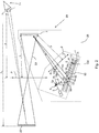
- Figure 1 shows a plan view of an optical assembly 1 according to an embodiment of the present invention.
- the optical assembly 1 comprises an image projector 2 according to an embodiment of the present invention, and a screen 3 in the form of a microlens array 3.
- the microlens array 3 comprises an array of microlenses 3'.
- the screen 3 is not limited to being a microlens array; the screen 3 may take any suitable form, for example the screen 3 may be a micromirror array or a diffuser such as a wall surface, white board or standard projector-screen.
- each of the microlenses 3' in the microlens array 3 is the same size; accordingly the pitch 'P' between the microlenses 3' in the microlens array 3 is constant across the microlens array 3.
- the microlens array may comprise microlenses which have different sizes such that the pitch between the microlenses in the microlens array differs across the microlens array.
- the pitch 'P' is the distance between the centre of a microlens to the centre of its neighbouring microlens.
- the image projector 2 comprises, a light source 4 which provides a collimated light beam 5; and a MEMS mirror 6 which is arranged such that it can receive the collimated light beam 5.
- the MEMS mirror 6 is configured such that it can oscillate about two orthogonal oscillation axes 7a,b so that it can scan the collimated light beam 5 in two-dimensions. It will be understood that the MEMS mirror 6 could be configured to oscillate about any number of oscillation axes. For example the MEMS mirror 6 could be configured to oscillate about a single oscillation axes so that it can scan the collimated light beam 5 in one dimension.
- the image projector 2 may comprise two MEMS mirrors, arranged to be in optical communication with each other, one of the MEMS mirrors being configured to oscillate about one oscillation axis and the second MEMS mirror being configured to oscillate about a second oscillation axis which is orthogonal to the first oscillation axis, so that collectively the two MEMS mirrors can scan the collimated light beam 5 in two-dimensions.
- the image projector 2 further comprises a multiple-beam-generator 8.
- the multiple-beam-generator 8 comprises a planar beam splitter 9 in the form of a planar beam splitter element 90 which is arranged to receive the collimated light beam 5 reflected by the MEMS mirror 6.
- the planar beam splitter element 90 reflects part 5b of the collimated light beam 5 and transmits another part 5a of the collimated light beam 5.
- the planar beam splitter element 90 is configured to have a beam splitting ratio of 40% reflection to 60% transmission.
- the multiple-beam-generator 8 further comprises a planar reflector 10 in the form of a planar reflector element 100(e.g. a mirror) which can receive, and subsequently reflect, the part 5a of the collimated light beam which is transmitted through the planar beam splitter element 90.
- the multiple-beam-generator 8 thus generates multiple light beams 15a-c from the single collimated light beam 5. Only three multiple light beams 15a-c are illustrated in the figure for clarity, but it should be understood that the multiple-beam-generator 8 could generate any number of multiple light beams.
- planar beam splitter element 90 and planar reflector element 100 are arranged to be in parallel.
- the planar beam splitter element 90 and planar reflector element 100 are further arranged such that the optical distance between the planar beam splitter element 90 and the planar reflector element 100 is greater than, or equal to, half the coherent length of the collimated light beam 5 (Typically the coherent length of the collimated light beam 5 will be a fixed value; the coherent length of the collimated light beam 5 is a property of the light source 4 which generates the collimated light beam 5 and is given as part of the specification for the light source 4).
- 'OD' is the optical distance
- 't' is the thickness of the planar beam splitter element 90
- ' ⁇ i ' is the incidence (AOI)of the collimated beam 5 (preferably the central beam) on the planar beam splitter element 90
- 'n1' is the refractive index of the material in which the collimated beam 5 passes before it is incident on the planar beam splitter element 90 (e.g.
- the material in which the collimated beam passes before it is incident on the planar beam splitter element 90 is air so 'n1' is equal to the refractive index 'air'), 'n' is the refractive index of planar beam splitter element 90, 'h' is the distance between the planar beam splitter element 90 and planar reflector element 100, 'n3' is the refractive index of the material which occupies the space 13 between planar beam splitter element 90 and planar reflector element 100.
- the space 13 between the planar beam splitter element 90 and planar reflector element 100 is occupied by 'air' (i.e.
- the multiple-beam-generator 8 may have any other suitable configurations.
- a block of material preferably transparent material (e.g glass), having a thickness 'h' , occupies the space 13.
- planar beam splitter 9 and planar reflector 10 are attached, abut to, or are formed on, opposite sides of the block of material thus the planar beam splitter 9 and planar reflector 10 are fixed distance 'h' apart ( 'h' in this case is equal to the thickness of the block of material).
- ⁇ 2 sin ⁇ 1 n 1 sin ⁇ i n
- ' ⁇ i ' is the incidence (AOI) of the collimated beam 5 (preferably the central beam) on the planar beam splitter element 90
- 'n1' is the refractive index of the material in which the collimated beam 5 passes before it is incident on the planar beam splitter element 90 (e.g. in this example the material in which the collimated beam passes before it is incident on the planar beam splitter 90 is air so 'n1' is equal to the refractive index 'air'), 'n' is the refractive index of planar beam splitter element 90.
- the multiple-beam-generator may comprise a glass block with a beam splitter coating on one surface of the glass block and a reflective coating on a second, opposite surface of the glass block.
- the beam splitter coating defines the planar beam splitter 9 and the reflective coating defines the planar reflector 10, and the optical distance is defined as: OD ⁇ h cos ⁇ 2 wherein 'h' is the distance between the beam splitter coating (i.e. the planar beam splitter 9) and the reflective coating (i.e.
- the image projector 2 further comprises a focusing lens 11 which is arranged to receive the multiple light beams 15a-c which are output from the multiple beam generator 8.
- the image projector 2 is arranged to be a distance 'F' equal to the focal length of the focusing lens 11, from the microlens array 3.
- the planar beam splitter 9 (planar beam splitter element 90) and planar reflector 10 (planar reflector element 100) causes the collimated light beam 5 to be split into multiple light beams 15a-c; because the optical distance is greater than, or equal to, half the coherent length of the collimated light beam the multiple beams are 'independent'; two beam are 'independent' if the difference between their optical paths is greater than the coherence length of the light source which generated the two beams.
- the light beam 15a is reflected only by the planar beam splitter element 90 whereas the consecutive (or neighbouring) light beam 15b is transmitted by the planar beam splitter element 90 and reflected by the planar reflector element 100 and transmitted again by the planar beam splitter element 90. Since the optical distance between the planar beam splitter element 90 and the planar reflector element 100 is greater than, or equal to, half the coherent length of the collimated light beam 5, the beam 15b travels an optical distance which is greater than the optical distance travelled by the beam 15a, by at least an amount equal to the coherence length of the light source 4. Thus consecutive (i.e. neighbouring) multiple light beams 15a and 15b are independent from each other. The other successive (i.e. neighbouring) multiple light beams (15c etc.) will also have optical paths which differ at least by a distance greater than or equal to the coherence length of the light source 4.
- planar beam splitter 9 planar beam splitter element 90
- planar reflector 10 the planar reflector element 100
- the multiple light beams 15a-c are then focused onto the same point 16 on the microlens array 3 using the focusing lens 11, so as to define a single pixel 17 of a projected image at point 16.
- the multiple independent light beams 15a-c each produce their own speckle and moire pattern; accordingly when the multiple light beams 15a-c are focused onto the same point 16 the speckle and moire patterns of each of the multiple independent light beams 15a-c will overlap at point 16 and thus will average-out; accordingly the speckle and moire which is visible to a viewer viewing the pixel 17 will be reduced. In practice it is the viewer's eyes that will average out the speckle and moire patterns upon viewing the pixel 17.
- Each pixel of the image is projected onto the microlens array 3 in this manner so that there is a reduction in speckle and moire pattern over the whole of the image projected on the microlens array 3.
- the manufacturer will typically calculate the smallest angle of incidence ' ⁇ i ' of the collimated light beam 5 (preferably the central beam) on the beam splitter 9.
- the smallest angle of incidence can be found for example, in the following manner: when the MEMS mirror 6 is at rest (i.e. the MEMS mirror 6 is not oscillating) the collimated light beam 5 reflected by the MEMS mirror 6 towards the beam splitter 9 defines what is referred to as the 'central beam.
- the manufacturer can adjust and measure the angle of incidence ' ⁇ i ' of the central beam on the beam splitter 9. Then, the smallest angle of incidence is equal to the angle of incidence ' ⁇ i ' of the central beam minus half the maximum angle over which the MEMS mirror can scan the collimated light beam 5 . If the value for the smallest angle of incidence is less than 0° then 0° is taken to be smallest angle of incidence. Then, using the optical distance 'OD' formula described above and using the known refractive index of the materials composing the multiple beam generator, the manufacturer can adjust the dimension 't' and 'h' such that the optical distance is greater than, or equal to, half the coherence length of the collimated light beam which is known.
- each light source generating one of the multiple independent light beams 15a-c. Since each of the light beams will come from different light sources the multiple light beams 15a-c will be "independent".
- a first light source could be used to generate the light beam 15a
- a second light source could be used to generate light beam 15b
- a third light source could be used to generate light beam 15c.
- no planar beam splitter 9 and planar reflector 10 is required; and the optical assembly may configured such that the first, second and third light sources generate respective light beams 15a-c which are passed directly to the focusing lens 11.
- Fig. 2 shows a perspective view of an optical assembly 20 according to a further embodiment of the present invention.
- the optical assembly comprises many of the same features of the optical assembly 1 shown in Figure 1 and like features are awarded the same reference numbers.
- the optical assembly 20 further comprises a head-up-display 21 which is arranged to receive light from the microlens array 3.
- the head-up-display 21 is arranged a distance 'L' from the microlens array 3 wherein 'L' is equal to: Ze ⁇ z / M wherein 'Ze' is a distance from a predefined position where the optical assembly 20 projects a virtual image 22 to a predefined position where a viewer should view the virtual image 22,, 'z' is a distance between the head-up-display 21 and the predefined position where a viewer should view the virtual image 22, and 'M' is the magnification of the head-up-display 21.
- the multiple light beams 15a-c which are focused onto the microlens array 3 by the focusing lens 11 are diffused by the microlens array 3.
- the diffused light 23 is passed through the head-up-display 21 to project a virtual image 22 at a location beyond the head-up-display 21.
- the virtual image 22 will be the same image as the image which is projected onto the microlens array 3, however the virtual image 22 may be larger(or smaller) as it may be magnified (or reduced) by the head-up-display 21.
- the optical-assembly 20 is configured such that it has a numerical aperture which is larger than the numerical aperture of a viewer 27 who is viewing the virtual image 22.
- the optical assembly 20 is configured such that it has a numerical aperture which is greater than a predefined numerical aperture value which represents the numerical aperture of a viewer; the predefined numerical aperture value is usually 0.016.
- 0.016 is the largest numerical aperture of a viewer having a pupil size between 1 to 10 mm for a virtual image position which is greater than, or equal to, 300 mm from the viewer.
- the numerical aperture of the optical assembly 20 is defined as: d / 2 / F . M wherein M is the magnification of the head-up-display 21 and F is the focal length of the of the focusing lens 11, and 'd' is the distance between two consecutive (i.e.
- the angle of incidence (AOI) ' ⁇ i ' , of the collimated light beam 5 (preferably the central beam) on the beam splitter element 90 is the angle between the collimated light beam 5 and the normal vector to the planar surface 9a of the planar beam splitter element 90.
- the AOI is the angle between a central beam and the normal vector to the planar surface 9a of the planar beam splitter element 90, wherein the central beam is the beam reflected towards the planar surface 9a when the MEMS mirror 6 is at rest (i.e. is not oscillating about oscillation axes 7a,b, in other words when the MEMS mirror 6 is not actuated).
- the central beam could use the central beam to make the calculation to find suitable dimensions for the thickness 't' of the planar beam splitter element 90 and for the distance 'h' between the planar beam splitter element 90 and the planar reflector element 100 to ensure that the 'OD' of the planar beam splitter element 90 and the planar reflector element 100 is greater than, or equal to, half the coherence length of the calumniated light beam 5 and that the numerical aperture of the optical assembly 20 is larger than the numerical aperture of the viewer 27:
- the central beam is found by measuring the angle between the collimated beam 5 projected on the beam splitter 9 when the MEMS mirror is at rest and the normal to the surface 9a of the beam splitter element 90.
- the refractive index of the planar beam splitter ( 'n' ) is a known value typically given from material datasheet. Suitable dimensions for 't' and 'h' are then chosen such that the optical distance 'OD' between the planar beam splitter element 90 and the planar reflector element 100 is greater than, or equal to, half the coherence length of the collimated light beam 5 and such that the numerical aperture of the optical assembly 20 (i.e. ( d / 2 )/( FM )) is larger than the numerical aperture of the viewer 27.
- the numerical aperture of the viewer 27 is defined by: y / 2 / Ze wherein y is the pupil size of the viewer 27, and Ze is a distance from a predefined position where the optical assembly 20 projects a virtual image 22 to a predefined position where a viewer will view the virtual image 22,.
- the pupil size depends of each viewer physiognomy and ambient light conditions and may vary between 1 to 10 mm in size.
- 'z' is preferably a predefined value and is typically between 500 to 1200 mm.
- a distance between 500 to 1200 mm is the typical distance between the eye of a driver of a car and the position of a head-up-display 21 in the car.
- 'M' is preferably a predefined value which is representative of the position of the virtual image 22; the position of the virtual image 22 can be changed by changing 'M'.
- a predefined value of for 'M' is given by the manufacturer.
- the magnification of the head-up-display M is preferably in the range of 1 to 20.
- the focal length F of the of the focusing lens is preferably in the range 5 to 1000 mm, and for d: t and h are preferably in the range 0.1 to 100 mm, and n is preferably in the range 1 to 4, ⁇ i is preferably in the range 0 to 89°, so that d is preferably in the range 9.5x10 -4 mm to 55 mm.
- the manufacturer will position the planar reflector element 100 and the planar beam splitter element 90 to achieve suitable values for 'h' , 'd' and will adjust the position of the microlens array 3 and/or the position of the image projector 2 and replace the focusing lens 11 with a focusing lens having a suitable focal length, so as to achieve a suitable value for 'F' , so as to ensure that the optical assembly 20 has a numerical aperture which is larger than the numerical aperture of a viewer 27 who is viewing the virtual image 22, and such that the optical distance (OD) between the planar beam splitter element 90 and the planar reflector element 100 is greater than, or equal to, half the coherence length of the calumniated light beam 5.
- the focusing lens having a suitable focal length is a focusing lens which can be positioned between the image projector 2 and microlens array 3 at a distance from the microlens array which is equal to the focal length 'F' of the focusing lens.
- 'M' is equal 6 for the system compactness.
- the pixel density must be at least 60 pixel/degree. This implies a condition on the virtual image size and resolution.
- the image can have a 720p resolution which means that the image has 1280x720 pixels.
- the image on the microlens array 3 measures 141x79 mm.
- the position of the microlens array 3 and/or the focusing lens 11 can be adjusted, and/or the focusing lens 11 can be replaced with a focusing lens having a suitable focal length, to achieve a suitable dimension for F which ensures that an image on the microlens array 3 is generated which is smaller or equal to the dimension 141x79 mm, otherwise the quality of the virtual image 22 will be lowered. In practice it will depend on the full optical scanning angle of the MEMS mirror 6.
- the right image size is always possible to obtain the right image size with a MEMS mirror projection system. If the image on the microlens array 3 is too small, one can replace the focusing lens 11 with a focusing lens with a suitable focal length, or move the image projector 2 further away from the microlens array 3 until the image dimension on the microlens array is small than or equal to the dimension 141x79 mm. Similarly if the if the image on the microlens array 3 is too large the focusing one can move the image projector 2 further away from the microlens array 3 and replace the focusing lens 11 with a focusing lens with a suitable focal length, until the image dimension on the microlens array is small than or equal to the dimension 141x79 mm.
- a suitable value for the thickness 't' of the planar beam splitter element 90 and a suitable value for the distance 'h' between the planar beam splitter element 90 and the reflector element 100 are then determined so that the the 'OD' between the planar beam splitter element 90 and the planar reflector element 100 is greater than, or equal to, half the coherence length of the collimated light beam 5 and the numerical aperture of the optical assembly 20 is larger than the numerical aperture of the viewer 27.
- the planar beam splitter element 90 and planar reflector element 100 are arranged in parallel and have an optical distance greater than half the coherent length of the collimated light beam 5, its image projector 2 offers the same advantages of reduced speckle and reduced moire patterns, as the image projector 2 of the optical assembly 1 shown in Figure 1 .
- the optical assembly 20 is configured such that it has a numerical aperture which is larger than the numerical aperture of a viewer 27 who is viewing the virtual image 22, the speckle patterns created by each of the multiple independent light beams 15a-c are de-correlated from each other; this results in a further reduction in speckle.
- the distance 'd' between two consecutive (i.e. two neighbouring) multiple beams 15a-c output from the multiple beam generator 8 measured prior to being incident on the focusing lens 11 and is equal to: d 2 t tan ⁇ 2 + h tan ⁇ 3 cos ⁇ i a better reduction in moire is achieved because this condition for 'd' ensures that the maxima of the interference pattern of at least one of the multiple light beams 15a-c more precisely overlays the minima of the interference pattern of at least one other of the multiple light beams 15a-c, and vice versa; in practice there will be many multiple light beams 15a-c and many more precise overlays of maxima and minima of the interference patterns for different light beams.
- d F tan 2 k + 1 ⁇ P 2
- ⁇ is the wavelength of the collimated light beam 5 and 'P' is the pitch of the microlens array 3 which is the distance from the center of a microlens in the microlens array 3 to the center of its neighbouring microlens
- k is an integer defining the order of the multiple beam generator 8
- ⁇ p is the angular separation between the interference maxima of one of the multiple light beams 15a-c
- Fig. 3 shows a perspective view of an optical assembly 30 according to a further embodiment of the present invention.
- the optical assembly 30 shown in Figure 3 has many of the same features of the optical assembly 20 shown in Figure 2 and like features are awarded the same reference numbers.
- the optical assembly 30 comprises an image projector 2b according to a further embodiment of the present invention, which comprises a multiple beam generator 80 having a glass block 81 between the planar beam splitter 9 and the planar reflector 10 (It will be understood that the invention is not limited to requiring a glass block; it will be understood that any suitable optically transparent material may be used in the multiple beam generator 80).
- a planar beam splitter coating 82 is provided on one surface 83 of the glass block 81 and a planar reflective coating 84 is provided on a second, opposite surface 85 of the glass block.
- the planar beam splitter coating 82 may comprise a semi-reflective material and the planar reflective coating 84 may comprise reflective material.
- planar beam splitter coating 82 defines the planar beam splitter 9 and the planar reflective coating 84 defines the planar reflector 10
- ⁇ 2 sin ⁇ 1 n 1 sin ⁇ i n
- ' ⁇ i ' is the incidence (AOI) of the collimated beam 5 (preferably the central beam) on the planar beam splitter coating 82
- 'n1' is the refractive index of the material in which the collimated beam 5 passes before it is incident on the planar beam splitter element 9 (e.g. in this example the material in which the collimated beam passes before it is incident on the planar beam splitter 9 is air so 'n1' is equal to the refractive index 'air'), 'n' is the refractive index of the planar beam splitter coating 82.
- 'd' is the distance 'd' between two consecutive (i.e. two neighbouring) multiple beams (e.g.15a and 15b, or, 15b and 15c) output from the multiple beam generator 80 prior to two consecutive multiple beams being incident on the focusing lens 11
- ' ⁇ i ' is the incidence (AOI) of the collimated beam 5 (preferably the central beam) on the planar beam splitter coating 82
- 'n' is the refractive index of the material the glass block 81.
- a manufacturer of the optical assembly 30 may choose a glass block having a suitable thickness 'T' such that the condition for 'h' mentioned above is met.
- the optical-assembly 30 is configured such that it has a numerical aperture which is larger than the numerical aperture of a viewer 27 who is viewing the virtual image 22.
- the optical assembly 30 is configured such that it has a numerical aperture which is greater than a predefined numerical aperture value which represents the numerical aperture of a viewer; the predefined numerical aperture value is usually 0.016.
- 0.016 is the largest numerical aperture of a viewer having a pupil size between 1 to 10 mm for a virtual image position which is greater than, or equal to, 300 mm from the viewer.
- the numerical aperture of the optical assembly 30 is defined as: d / 2 / F . M wherein M is the magnification of the head-up-display 21 and F is the focal length of the of the focusing lens 11, and 'd' is the distance between two consecutive (i.e. two neighbouring) multiple beams 15a-c output from the multiple beam generator 8 measured prior to being incident on the focusing lens 11 and is given by the equation
- the angle of incidence (AOI), ' ⁇ i ' , of the collimated light beam 5 on the beam splitter coating 82 is the angle between the collimated light beam 5 and the normal vector to the planar beam splitter coating 82.
- the AOI is the angle between a central beam of the collimated light beam 5 and the normal vector to the planar beam splitter coating 82 wherein the central beam of the collimated light beam 5 is the beam reflected towards the planar beam splitter coating 82 when the MEMS mirror 6 is at rest.
- the central beam is found by measuring the angle between the collimated beam 5 projected on the beam splitter 9 when the MEMS mirror is at rest and the normal to the surface 83 of the beam splitter element 9.
- the refractive index of the planar beam splitter is a known value typically given from material datasheet. Suitable dimensions for 'h' are then chosen such that 'OD' between the planar beam splitter coating 82 and the planar reflective coating 84 is greater than, or equal to, half the coherence length of the collimated light beam 5 and such that the numerical aperture of the optical assembly 30 (i.e. ( d / 2 )/( FM )) is larger than the numerical aperture of the viewer 27 .
- the numerical aperture of the viewer 27 is defined by (y / 2) / (Ze) wherein y is the pupil size of the viewer 27, and Ze is a distance from a predefined position where the optical assembly 30 projects a virtual image 22 to a predefined position where a viewer will view the virtual image 22,.
- the pupil size depends of each viewer physiognomy and ambient light conditions and may vary between 1 to 10 mm in size.
- 'L' is the distance between the microlens array 3 and the head-up-display 21 and 'z' is the distance between a predefined position for the eye of a viewer 27 and the head-up-display 21.
- 'z' is preferably a predefined value and is typically between 500 to 1200 mm.
- a distance between 500 to 1200 mm is the typical distance between the eye of a driver of a car and the position of a head-up-display 21 in the car.
- 'M' is preferably a predefined value which is representative of the position of the virtual image 22; the position of the virtual image 22 can be changed by changing 'M'.
- a predefined value of for 'M' is given by the manufacturer.
- the magnification of the head-up-display M is preferably in the range of 1 to 20.
- the focal length F of the of the focusing lens is preferably in the range 5 to 1000 mm, and for d: h is preferably in the range 0.1 to 100 mm, and n is preferably in the range 1 to 4, ⁇ i is preferably in the range 0 to 89°, so that d is preferably in the range 9.5x10 -4 mm to 55 mm.
- the manufacturer of the optical assembly 30 may choose a glass block having a suitable thickness 'T' such that the condition for 'h' mentioned above is met and will adjust the position of the microlens array 3 and/or the projector 2 and replace the focusing lens 11 with a focusing lens having a suitable focal length, to achieve a suitable value for 'F' , so as to ensure that the optical assembly 30, is configured such that it has a numerical aperture which is larger than the numerical aperture of a viewer 27 who is viewing the virtual image 22, and such that optical distance between the planar beam splitter coating 82 and the planar reflective coating 84 is greater than, or equal to, half the coherence length of the calumniated light beam 5.
- 'M' is equal 6 for the system compactness.
- the pixel density must be at least 60 pixel/degree. This implies a condition on the virtual image size and resolution.
- the image can have a 720p resolution which means that the image has 1280x720 pixels.
- the image on the microlens array 3 measures 141x79 mm.
- the position of the microlens array 3 and/or the focusing lens 11 can be adjusted, and/or the focusing lens 11 can be replaced with a focusing lens having a suitable focal length, to achieve a suitable dimension for F which ensures that an image on the microlens array 3 is generated which is smaller or equal to the dimension 141x79 mm, otherwise the quality of the virtual image 22 will be lowered. In practice it will depend on the full optical scanning angle of the MEMS mirror 6.
- the right image size is always possible to obtain the right image size with a MEMS mirror projection system. If the image on the microlens array 3 is too small, one can replace the focusing lens 11 with a focusing lens with a suitable focal length, or move the image projector 2b further away from the microlens array 3 until the image dimension on the microlens array is small than or equal to the dimension 141x79 mm. Similarly if the if the image on the microlens array 3 is too large the focusing one can move the image projector 2 further away from the microlens array 3 and replace the focusing lens 11 with a focusing lens with a suitable focal length, until the image dimension on the microlens array is small than or equal to the dimension 141x79 mm.
- a suitable value for the distance 'h' between the planar beam splitter coating 82 and the planar reflective coating 84 are then determined so that the 'OD' between the planar beam splitter coating 82 and the planar reflective coating 84 is greater than, or equal to, half the coherence length of the collimated light beam 5 and the numerical aperture of the optical assembly 30 is larger than the numerical aperture of the viewer 27.
- planar beam splitter coating 82 and planar reflective coating 84 are arranged in parallel and have an optical distance greater than half the coherent length of the collimated light beam 5, its image projector 2b offers the same advantages of reduced speckle and reduced moire patterns, as the image projector 2 of the optical assembly 1 shown in Figure 1 .
- the optical assembly 30 is configured such that it has a numerical aperture which is larger than the numerical aperture of a viewer 27 who is viewing the virtual image 22, the speckle patterns created by each of the multiple independent light beams 15a-c are de-correlated from each other; this results in a further reduction in speckle.
- the optical assembly 30 can achieve an improved reduction in moire is achieved because this condition for 'h' ensures that the maxima of the interference pattern of at least one of the multiple light beams 15a-c more precisely overlays the minima of the interference pattern of at least one other of the multiple light beams 15a-c, and vice versa; in practice there will be many multiple light beams 15a-c and many more precise overlays of maxima and minima of the interference patterns for different light beams.
- 'h' is equal to 5.12 mm.
- Figure 7 illustrates how the moire reduction is achieved in the embodiments shown in Figures 2 and 3 .
- Figure 7 illustrates the maxima 71 of the interference pattern of the second light beam 15b overlaying the minima 72 of the interference pattern of the first light beam 15a, and the maxima 73 of the interference pattern of the first light beam 15b overlaying the minima (not visible in figure) of the interference pattern of the second light beam 15b.
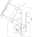
- Fig. 4 shows a plan view of an optical assembly 40 according to a further embodiment of the present invention.
- the optical assembly 40 shown in Figure 4 has many of the same features as the optical assembly 1 shown in Figure 1 and like features are awarded the same reference numbers. It will be understood that the optical assembly 40 could have any one or more of the features or conditions of the optical assemblies 20,30 shown in Figures 2 an 3.
- the optical assembly 40 according to a further embodiment of the present invention which comprises an image projector 2c according to a further embodiment of the present invention, which has a multiple beam generator 41 which comprises a glass block 46 (It will be understood that the invention is not limited to requiring a glass block 46; it will be understood that any suitable optically transparent material may be used in the multiple beam generator 41).
- planar beam splitter coating 42 defines the planar beam splitter 9 and the planar reflective coating 43 defines the planar beam reflector 10.
- the first and second surfaces 49a,b are flat and are parallel to one another so that the planar beam splitter coating 42 and planar reflective coating 43 are parallel and planar.
- planar beam splitter coating 42 is configured such that light 45 reflected from the planar reflector coating 43 passes directly from the planar reflector coating 43 to the focusing lens 11 without passing through the planar beam splitter 42. This can be achieved by positioning the planar beam splitter coating 42 on only a portion of the first surface 49a of the glass block 46 so that the planar beam splitter coating 42 does not overlay the whole of the planar reflector coating 43 and/or by providing a planar beam splitter coating 42 which has a smaller perimeter than the perimeter of the planar reflector coating 43 so that the planar beam splitter coating 42 does not overlay the whole of the planar reflector coating 43.
- planar beam splitter coating 42 is provided on only a portion of the first surface 49a of the glass block 46 so that the planar beam splitter coating 42 does not overlay the whole of the planar reflector coating 43. Collimated light beam 45 which passes through the planar beam splitter coating 42 is thus reflected by the planar reflector coating 43 directly to the focusing lens 11 without passing through the planar beam splitter coating 42.
- the multiple beam splitter 41 comprises a glass block 46 and a planar beam splitter coating 42 on one surface of the glass block 46 defines the planar beam splitter coating 42, while a planar reflective coating 43 provides on an opposite surface of the glass block 46 defines the planar reflector 43.
- the light beams reflected 45 by the planar reflector 43 are passed directly from the planar reflector 43 to the focusing lens 11 without passing through the planar beam splitter 42 only two beams 48a,48b are generated by the multiple beam splitter 41 from a single collimated light beam 45 and these two beams 48a,b have similar optical power.
- each of the two beams 48a,b When these two beams 48a,b are focused to the same point 16 on the microlens array 3 by the focusing lens 11 each of the two beams 48a,b will produce an interference pattern of the same intensity and which are angularly shifted with respect to one another such as the maxima of the interference pattern of one of the light beams 48a are located at the minima of the interference pattern of the other light beam 48b;because the two beams 48a,b have the same optical power the interference patterns will average out perfectly to obtain a constant optical power image with reduced moire.
- the multiple beam generator may simply take the form of the multiple beam generator 8 of the image projector 2 of the optical assembly 1 shown in Figure 1 , which comprises a planar beam splitter element 90 and planar reflector element 100 as mechanically independent structures separated by an air gap 13.
- planar beam splitter element 90 and planar reflector element 100 may be simply position so that the planar beam splitter element 90 does not overlay the planar reflector element 100 completely; or the planar beam splitter element 90 could be dimensioned to have a perimeter which is smaller than the perimeter of the planar reflector element 100 so that the planar beam splitter element 90 does not overlay the planar reflector element 100 completely; thereby allowing light 45 reflected from the planar reflector element 100 to pass directly from the planar reflector element 100 to the focusing lens 11 without passing through the planar beam splitter element 90.
- Figure 6 illustrates an optical assembly 60 according to further embodiment of the present invention.
- the optical assembly 60 contains many of the same features of the optical assemblies (1,20,30,40) shown in Figures 1-4 and like features are awarded the same reference numbers. It will be understood that the optical assembly 60 could contain any of the features of the embodiments illustrated in Figures 1-4 .
- the optical assembly 60 comprises a plurality of multiple-beam-generators 61,62 , which are arranged to be in optical communication with one-another.
- Each of the multiple-beam-generators 61,62 may comprise one or more of the features of the multiple-beam-generators 8,41,80 illustrated in the any of the other optical assembly embodiments already described.
- Each of the plurality of multiple-beam-generators have a different orientation such that they each lie on, or are parallel to, differently orientated planes 64,65.
- the planar beam splitter 9 and planar reflector 10 of the multiple beam generator 61 lie on, or are parallel to, a first plane 64 and the planar beam splitter 9 and planar reflector 10 of the multiple beam generator 62 lie on, or are parallel to, a second plane 65.
- the first plane 64 and second plane 65 are orientated such that there is an angle of 120° between the planes 64,65.
- the first plane 64 of the multiple beam generator 61 is orientated along the (1 0 1) and the second plane 65 of the multiple beam generator 62 is orientated along the (-1 -1 0).
- the orientation of a plane is defined by a vector (x y z) which is normal to the plane.
- the first plane 64 is orientated perpendicular to the (1 0 1) vector 66 while the second plane 65 is orientated perpendicular to the (-1 -1 0) vector 67.
- optical assembly 60 illustrates only two multiple-beam-generators 61,62 which lie on different planes 64,65 any number of multiple-beam-generators could be provided in the optical assembly 60, each multiple-beam-generator being in optical communication with another multiple-beam-generator and the planar beam splitter 9 and planar reflector 10 of each of the multiple beam generators lying on, or being parallel to, differently orientated planes.
- the optical assembly 60 comprises two multiple beam generators 61,62 which are in optical communication and which lie on, or are parallel to, differently orientated planes 64,65 this enables a further reduction in speckle and moire to be achieved because a 2D array 69 of multiple beams is created when using two multiple beam generators 61,62.
- Each of the multiple beams in the 2D multiple beam array 69 are focused by the focusing lens 11 to the same point 16 on the microlens array 3 to define a single pixel 17.
- Multiple speckle patterns or moire patterns are then created at point 16 such as they average out in 2D providing improved speckle and moire reduction.
- Each pixel of the projected image is projected in this manner so that there is a reduction in speckle and moire over the whole of the projected image.
- the microlens array 3 is configured to have different sized microlenses as shown in Figure 5a.
- Figure 5a shows a perspective view of an alternative configuration for the screen 3 which can be used in any of the embodiments of the present invention.
- Figure 5a illustrates a screen 3 in the form of a microlens array 50 which comprises differently sized microlenses 51. Accordingly in the microlens array 50 the pitch 'P' between the microlenses 51 in the microlens array 50 differs across the microlens array 50. More precisely in this example the sizes of the microlenses 51 in the microlens array 50 increase from a centre column 53 of microlenses towards the outermost column 54 of microlenses of the microlens array 51. The size of the microlenses along each respective column 53,54 are equal; however in a variation of the embodiment the size of the microlenses along each respective column 53,54 may increase or decrease.
- the sizes of the microlenses 51 in the microlens array 50 can increase from a centre row 56 of microlenses towards the outermost row of microlenses 57 of the microlens array 51.
- the size of the microlenses along each respective row 56,57 may be equal; however in a further variation of the invention the size of the microlenses along each respective row 56,57 may increase or decrease.
- the size of the microlenses 51 in the microlens array 50 is such that the pitch between consecutive microlenses 51, is equal to: P eff / cos ⁇ scan wherein P eff is a predefined effective pitch value and ⁇ scan is the angle of incidence of a light beam emitted from the projector device on that microlenses 51.
- the 'effective pitch' is the projection of the pitch of the microlenses along the incoming light direction ⁇ scan. .
- Fig. 5b illustrates the problem which arises with microlens arrays in which all microlenses of the microlens array are of equal size:
- the angle of incidence of the light beam on microlens array will change over the scan amplitude; as the light beam is scanned towards the outermost microlenses in the angle of incidence will be reduced so that light beam experiences an 'effective pitch' which is lower than the physical distance between the centres of neighbouring microlenses; this can result in a changing interference pattern along the scanning amplitude (wherein the scanning amplitude is the amplitude over which the oscillating MEMS mirror 6 scans the collimated light beam 5).
- the microlens array shown in Figure 5a resolves this problem; since the microlenses are sized such that the pitch between consecutive microlenses 51 is equal to (P eff / cos ⁇ scan ) it compensates for the scanning of the light beam by the MEMS mirror 6 so that 'effective pitch' experienced by the light beam is equal across the whole scanning amplitude.
- the microlenses 51 in the microlens array may be further sized such that they compensate for the change in angle of incidence of the collimated light 5 beam on the planar beam splitter 9, which occurs when the collimated light beam 5 is scanned by the oscillating MEMS mirror 6.
- the thickness 'T' of the glass block 81 between the beam splitter coating 82 and the reflective coating 84 defines the distance 'h' between the planar beam splitter 9 (beam splitter coating 82) and the planar reflector 10 (reflective coating 84)), thus the optical assembly 30 is configured such that the above mentioned condition for 'h' is met by choosing a glass block 81 with the appropriate thickness.
- the screen 3 shown in Figure 5a is in the form of a microlens array 50
- the screen 3 could alternatively be in the form of a micromirror array having the same pitch conditions between consecutive micromirrors as those described above for the microlens array 50.
- any of the above described optical assemblies could have a screen 3 in the form shown in Figures 5a .
- the screen 3 may alternatively comprise a micromirror array and similarly the pitch between consecutive micromirrors in the micromirror array may be equal to (P eff / cos ⁇ scan ).
- the focusing lens 11 may take any suitable form; for example the focusing lens 11 may be a simple converging lens, a plano convex lens, double convex lens or a F-theta lens. Additionally, or alternatively, the focusing lens 11 may be further configured to correct chromatic aberration; for example the focusing lens 11 may be an achromatic lens such as an achromatic doublet or lens with a surface grating which is configured to correct chromatic aberration.
- the a light source 4 may be configured to emit collimated light beams 5 in pulses, each pulse of light defining a single pixel of a projected image.
- Each pulse may comprise the amount of red, green and blue light beams necessary for defining a corresponding pixel of the projected image; thus in this case the red, green and blue light beams are emitted by the light source simultaneously in the same pulse.
- the light source 4 may be configured to emit pulses of green, red and blue light beams consecutively in independent pulses, rather than emitting them simultaneously in the same pulse.
- the time of the emission of the green, red and blue light beams is synchronized with the orientation of the oscillating MEMS mirror 6 so that the red, green and blue light beams are incident at predefined respective positions on the focusing lens 11.
- the predefined respective positions are such that the red, green and blue light beams are focused to same point on the screen 3 by the focusing lens 11.
- the chromatic aberration of the focusing lens 11 is a known value; typically known from the lens manufacturer or it can be calculated using well known equations in optics; it can also be measured using a detector placed after the focusing lens 11. Thus, the chromatic aberration is known for each pixel of a projected image.
- the optical assembly can also include a position sensor which is configured to measure the position and the speed of oscillation the MEMS mirror 6 about its oscillation axes 7a,7b, so that the position and the speed of oscillation of the MEMS mirror 6 is known at all-times.
- the blue light portion of a pixel is offset by a fixed distance of 'x mm' with respect to the green light portion of a pixel at a given scanning angle ⁇ of the MEMS mirror.
- the speed of oscillation of the MEMS mirror 6 is ' ⁇ ' in degree/second and the scanned spot 16 moves on the screen 3 at a speed 'v' in mm/s.
- the light source 4 is configured to emit independent pulses of blue, red and green light, consecutively, for each pixel to be projected; the red, green and blue pulses combine on the screen 3 to form an pixel.
- the amount of blue, red and green light in the each pulse is according to the amount of blue, red and green colour in the pixel to be projected.
- 't' defines the time delay between consecutive red, green and blue pulses.
- the time delay of the emission of the green, red and blue light beams can vary for each position of the MEMS mirror 6 because the aberration and the speed of the MEMS mirror 6 also vary throughout the oscillation amplitude of the MEMS mirror 6 will vary.
- the synchronization of the emission of the independent red, green and blue light beams from the light source 4 with the oscillation of the MEMS mirror, so that the red, green and blue light beams are incident on predefined respective points on the focusing lens 11 such that they are focused by the focusing lens 11 onto the same point on the screen 3, can be used to correct chromatic aberration.
Landscapes
- Physics & Mathematics (AREA)
- Optics & Photonics (AREA)
- General Physics & Mathematics (AREA)
- Engineering & Computer Science (AREA)
- Multimedia (AREA)
- Signal Processing (AREA)
- Projection Apparatus (AREA)
- Mechanical Optical Scanning Systems (AREA)
- Optical Elements Other Than Lenses (AREA)
- Transforming Electric Information Into Light Information (AREA)
- Mechanical Light Control Or Optical Switches (AREA)
Description
- The present invention concerns an image projector and optical assembly which comprises the image projector, which is suitable for use in a head-up-display, and which is configured to achieve a reduction in both speckle and moiré.
- In projection assemblies light projected onto a projection screen can cause speckle which reduces the resolution of the projected image. For example, in projection assemblies which comprise a head-up-display, coherent light is projected onto the head-up-display so that a projected image appears on the head-up-display.
- In projection assemblies which comprise a head-up-display the head-up-display is typically provided in the form of a transparent screen (e.g. a windscreen of a vehicle); the coherent light is projected onto the transparent screen so that a virtual image is visible at some point beyond the screen. The surface of the transparent screen is never perfectly smooth; accordingly when the coherent light is projected onto the transparent screen the transparent screen will randomly diffuse the coherent light thereby creating random inference which causes speckle which reduces the resolution of the virtual image.
- In order to resolve this problem of speckle which occurs in projection assemblies which comprise a head-up-displays, it is known to provide the head-up-display in the form of a microlens array (or in the form of a micromirror array). The surface of each lens in the microlens array is perfectly smooth, accordingly it will not randomly diffuse the coherent light it receives; therefore no random inference or speckle is created. However, when the coherent light is projected onto the microlens array the microlens array will cause regular diffraction and regular interference known as moire. The moire appears as variations in intensity across the virtual image; accordingly the moire compromises the quality of the projected image.
- Many solutions in the prior art address exclusively the problem of speckle or moire however none of the solutions provide an single adequate solutions with addresses both problems.
US20040257664 discloses a solution to speckle but this solution is not effective to reduce moire because the system is not configured to create an angle between the multiple beams which would allow the interference of the first beam to be averaged with the interference of the second beam by having the interference maxima of the second beam fit between the interference maxima of the first beam. - Other solutions of the prior art use anti-moire filters or antialiasing filters but these solutions provide no means for adequate speckle reduction; moreover these solutions cannot incorporate a speckle reduction means such as a microlens array because they project polarised light and a microlens array cannot reduce the speckle in polarized light because the speckle or moire pattern for microlens are the same for both orthogonal orientation of the polarization.
- It is an aim of the present invention to mitigate or obviate at least some of the above-mentioned problems.
-
JP 2013 254031 A -
EP 1329760 A2 describes a coherence reducer having a light path that divides a received coherent light beam into several sub-beams so that the sub-beams are offset with respect to each other in and/or transverse to the beam direction and/or propagate in different directions. -
WO 2014/111163 A1 describes a method of reducing speckle effects in a projected image which is displayed on a display surface, comprising the steps of, transmitting an input light beam to a first interferometer, generating a plurality of primary transmit beams at the first interferometer using the input light beam, using the plurality of primary transmit beams to generate interference fringes at a display surface. - The present invention is defined in
claim 1. Preferred features are recited in the dependent claims. - According to an aspect of the present invention there is provided an image projector comprising, a light source for providing a light beam; a MEMS mirror which is arranged such that it can receive the light beam, and which can oscillate about at least one oscillation axis to scan said light beam; one or more multiple-beam-generators each of the one or more multiple-beam-generators comprising, a planar beam splitter which is arranged to receive the light beam reflected by the MEMS mirror, and a planar reflector which can receive the part of the light beam which is transmitted through the planar beam splitter, so that each of the one or
more multiple-beam-generators can generated multiple beams, and wherein the planar beam splitter and planar reflector are arranged to be in parallel; and a focusing lens which is arranged to receive multiple beams which are generated by the one or more multiple-beam-generators; wherein, in each of the one or more multiple-beam-generators the distance (h) between the planar beam splitter and planar reflector is such that the optical distance (OD) between the planar beam splitter and planar reflector is greater than, or equal to, half the coherent length of the light beam. - Preferably the light beam is a collimated light beam. Preferably the light source is configured to provide a collimated light beam.
- The one or more multiple beam generators may comprise a planar beam splitter element, which defines the planar beam splitter, and a planar reflector element, which defines the planar reflector, arranged in parallel and spaced apart such that there is an air-gap between the planar beam splitter element and a planar reflector element and wherein the optical distance (OD) is defined as:


- The one or more multiple beam generators may comprise a block of transparent material, and a planar coating of semi-reflective material on a first surface of the block, which defines the planar beam splitter, and a planar coating of reflective material provided on a second, opposite, surface of the block which defines the planar reflector, and wherein the optical distance (OD) is defined as:


- The image projector may comprise a plurality of multiple-beam-generators, which are arranged to be in optical communication, and wherein the planar beam splitter and planar bean reflector of each of the plurality of multiple-beam-generators lie on, or are arranged parallel to, differently orientated planes.
- The planar beam splitter may be configured to have a beam splitting ratio of 40% reflection to 60% transmission. Preferably the planar beam splitter is configured to have a beam splitting ratio of 45% reflection and 55% transmission.
- The planar beam splitter may be arranged such that the part of the light beam which has transmitted through the planar beam splitter and is reflected by the planar reflector, can pass directly to the focusing lens without passing through the planar beam splitter. For example the position of the planar beam splitter may be offset from the position of planar reflector so that the planar beam splitter does not completely overlay the planar reflector. Alternatively the planar beam splitter may have a smaller dimension than the planar reflector so that the planar beam splitter does not completely overlay the planar reflector. A combination of both offset positioning and smaller dimensions is also possible.
- According to the present invention there is provided an optical assembly comprising, an image projector according to any one of the preceding claims, and a screen arranged to receive light which has passed through the focusing lens, wherein the screen is configured to diffuse light it receives, and a head-up-display which is arranged to receive light which is diffused by the screen.
- The screen is preferably a diffuser; the screen may be a microlens array, a micromirror array, or a white-board.
- Preferably the image projector is positioned such that the focusing lens of the image projector is located at a distance from the screen which is equal to the focal length of the focusing lens.
- The optical assembly is configured to have a numerical aperture which is greater than the numerical aperture of the viewer. The optical assembly is configured to have a numerical aperture which is greater than 0.016. The numerical aperture of the the optical assembly is defined as (d/2)/(F.M), wherein M is the magnification of the head-up-display, and F is the focal length of the of the focusing lens, and d is the distance between two consecutive multiple light beams which are output from the multiple beam generator and prior to said multiple light beams being incident on the focusing lens.
- The optical assembly may be configured such that 'd' satisfies the condition:


- The optical assembly may be configured such that 'd' satisfies the condition:

- The optical assembly may be configured such that 'd' satisfies the condition:


- k can be any integer: 0,1,2,3,4,... it should preferably be chosen such that it will make the OD greater than or equal to half the coherence length of the coherent light beam. It can also be chosen so as to ensure that the OD is greater than or equal to half the coherence length of the coherent light beam for all the wavelength λ used in the light beam (for example where h=5.12 choosing k = 4,5,6 for the light bean red, green, blue respectively).
- The optical assembly may be configured such that the distance 'h' between the planar beam splitter and the planar reflector is equal to:

- Preferably the distance 'h' between the planar beam splitter and the planar reflector is between 0.5 mm and 10 mm. More preferably the distance 'h' between the planar beam splitter and the planar reflector is between 3mm-4mm.
- The screen comprises a microlens array. The microlens array comprises different sized microlenses so that the microlens array has a plurality of different pitch lengths between microlenses in the microlens array.
- The screen may comprise a micromirror array. The micromirror array may comprise different sized micromirrors so that the micromirror array has a plurality of different pitch lengths between micromirrors. The pitch (P) between consecutive microlenses, or micromirrors, may be equal to:

- The pitch (P) between consecutive microlenses, or micromirrors, may be equal to:

- In a further embodiment the consecutive emission of independent red, green and blue light beams from the light source is synchronization with the oscillation of the MEMS mirror, so that the red, green and blue light beams are incident on predefined respective points on the focusing lens, so as to compensate for chromatic aberration ensuring that the red, green and blue light beams are focused by the focusing lens onto the same point on the screen. Preferably the red, green and blue light beams define the red, green and blue colours of a pixel; and therefore the amount of red, green and blue light in each beam is proportional to the amount of red, green and blue light in the pixel to be projected.
- The invention will be better understood with the aid of the description of embodiments of the present invention, which are given by way of example only, and illustrated by the figures, in which:
-
Fig. 1 shows a plan view of an optical assembly according to an example not covered by the present invention; -
Fig. 2 shows a perspective view of an optical assembly according to an example not covered by the present invention; -
Fig. 3 shows a perspective view of an optical assembly according to an example not covered by the present invention; -
Fig. 4 shows a plan view of an optical assembly according to an example not covered by the present invention; -
Fig. 5a provides front view of a configuration for the screen which is used in the optical assembly of the present invention;Fig. 5b illustrates the problem which arises with the use of standard microlens arrays as a screen; -
Fig. 6 provides a perspective view of an optical assembly according to a further embodiment of the present invention; -
Figure 7 illustrates the maxima of the interference pattern of a light beam overlaying the minima of the interference pattern of another light beam. -
Figure 1 shows a plan view of anoptical assembly 1 according to an embodiment of the present invention. Theoptical assembly 1 comprises animage projector 2 according to an embodiment of the present invention, and ascreen 3 in the form of amicrolens array 3. Themicrolens array 3 comprises an array of microlenses 3'. - It should be understood that the
screen 3 is not limited to being a microlens array; thescreen 3 may take any suitable form, for example thescreen 3 may be a micromirror array or a diffuser such as a wall surface, white board or standard projector-screen. Furthermore, in this exemplary embodiment each of the microlenses 3' in themicrolens array 3 is the same size; accordingly the pitch 'P' between the microlenses 3' in themicrolens array 3 is constant across themicrolens array 3. However, as will be described with respect to another embodiment of the invention, the microlens array may comprise microlenses which have different sizes such that the pitch between the microlenses in the microlens array differs across the microlens array. The pitch 'P' is the distance between the centre of a microlens to the centre of its neighbouring microlens. - The
image projector 2 comprises, alight source 4 which provides acollimated light beam 5; and aMEMS mirror 6 which is arranged such that it can receive the collimatedlight beam 5. TheMEMS mirror 6 is configured such that it can oscillate about twoorthogonal oscillation axes 7a,b so that it can scan the collimatedlight beam 5 in two-dimensions. It will be understood that theMEMS mirror 6 could be configured to oscillate about any number of oscillation axes. For example theMEMS mirror 6 could be configured to oscillate about a single oscillation axes so that it can scan the collimatedlight beam 5 in one dimension. In a further variation theimage projector 2 may comprise two MEMS mirrors, arranged to be in optical communication with each other, one of the MEMS mirrors being configured to oscillate about one oscillation axis and the second MEMS mirror being configured to oscillate about a second oscillation axis which is orthogonal to the first oscillation axis, so that collectively the two MEMS mirrors can scan the collimatedlight beam 5 in two-dimensions. - The
image projector 2 further comprises a multiple-beam-generator 8. The multiple-beam-generator 8 comprises aplanar beam splitter 9 in the form of a planarbeam splitter element 90 which is arranged to receive the collimatedlight beam 5 reflected by theMEMS mirror 6. The planarbeam splitter element 90 reflectspart 5b of the collimatedlight beam 5 and transmits anotherpart 5a of the collimatedlight beam 5. The planarbeam splitter element 90 is configured to have a beam splitting ratio of 40% reflection to 60% transmission. - The multiple-beam-
generator 8 further comprises aplanar reflector 10 in the form of a planar reflector element 100(e.g. a mirror) which can receive, and subsequently reflect, thepart 5a of the collimated light beam which is transmitted through the planarbeam splitter element 90. The multiple-beam-generator 8 thus generates multiplelight beams 15a-c from the single collimatedlight beam 5. Only three multiplelight beams 15a-c are illustrated in the figure for clarity, but it should be understood that the multiple-beam-generator 8 could generate any number of multiple light beams. - The planar
beam splitter element 90 and planar reflector element 100are arranged to be in parallel. The planarbeam splitter element 90 and planar reflector element 100are further arranged such that the optical distance between the planarbeam splitter element 90 and theplanar reflector element 100 is greater than, or equal to, half the coherent length of the collimated light beam 5 (Typically the coherent length of the collimatedlight beam 5 will be a fixed value; the coherent length of the collimatedlight beam 5 is a property of thelight source 4 which generates the collimatedlight beam 5 and is given as part of the specification for the light source 4). The optical distance is defined as:

beam splitter element 90, 'Θi' is the incidence (AOI)of the collimated beam 5 (preferably the central beam) on the planarbeam splitter element 90, 'n1' is the refractive index of the material in which the collimatedbeam 5 passes before it is incident on the planar beam splitter element 90 (e.g. in this example the material in which the collimated beam passes before it is incident on the planarbeam splitter element 90 is air so 'n1' is equal to the refractive index 'air'), 'n' is the refractive index of planarbeam splitter element 90, 'h' is the distance between the planarbeam splitter element 90 andplanar reflector element 100, 'n3' is the refractive index of the material which occupies thespace 13 between planarbeam splitter element 90 andplanar reflector element 100. In this embodiment thespace 13 between the planarbeam splitter element 90 andplanar reflector element 100 is occupied by 'air' (i.e. there is anair gap 13 between the planarbeam splitter element 90 and planar reflector element 100) and the collimatedbeam 5 passes through 'air' before it is incident on the planarbeam splitter element 90 such that n1=n3=1, so that in this example the optical distance is defined as:
- While this example shown in
Figure 1 illustrates the multiple-beam-generator 8 as comprising a planarbeam splitter element 90 andplanar reflector element 100 defining theplanar beam splitter 9 and planar reflector respectively, and being separated by an air gap; it should be understood that the multiple-beam-generator 8 may have any other suitable configurations. For example in another embodiment a block of material, preferably transparent material (e.g glass), having a thickness 'h', occupies thespace 13. Theplanar beam splitter 9 andplanar reflector 10 are attached, abut to, or are formed on, opposite sides of the block of material thus theplanar beam splitter 9 andplanar reflector 10 are fixed distance 'h' apart ('h' in this case is equal to the thickness of the block of material). In this case the optical distance is defined as:
planar beam splitter 9 and planar reflector 10 (i.e. the thickness of the block of material) and Θ2 is
beam splitter element 90, 'n1' is the refractive index of the material in which the collimatedbeam 5 passes before it is incident on the planar beam splitter element 90 (e.g. in this example the material in which the collimated beam passes before it is incident on theplanar beam splitter 90 is air so 'n1' is equal to the refractive index 'air'), 'n' is the refractive index of planarbeam splitter element 90. - For example, in a variation of the embodiment shown in
Figure 1 , the multiple-beam-generator may comprise a glass block with a beam splitter coating on one surface of the glass block and a reflective coating on a second, opposite surface of the glass block. In this variation the beam splitter coating defines theplanar beam splitter 9 and the reflective coating defines theplanar reflector 10, and the optical distance is defined as:

planar beam splitter 9, 'n1' is the refractive index of the material in which the collimatedbeam 5 passes before it is incident on the planar beam splitter 9 (e.g. the refractive index 'air'), 'n' is the refractive index of planar beam splitter 9.Theimage projector 2 further comprises a focusinglens 11 which is arranged to receive the multiplelight beams 15a-c which are output from themultiple beam generator 8. - The
image projector 2 is arranged to be a distance 'F' equal to the focal length of the focusinglens 11, from themicrolens array 3. - Advantageously, in the embodiment shown in
Figure 1 , the planar beam splitter 9 (planar beam splitter element 90) and planar reflector 10 (planar reflector element 100) causes the collimatedlight beam 5 to be split into multiplelight beams 15a-c; because the optical distance is greater than, or equal to, half the coherent length of the collimated light beam the multiple beams are 'independent'; two beam are 'independent' if the difference between their optical paths is greater than the coherence length of the light source which generated the two beams. Referring to theoptical assembly 1 illustrated inFigure 1 thelight beam 15a is reflected only by the planarbeam splitter element 90 whereas the consecutive (or neighbouring)light beam 15b is transmitted by the planarbeam splitter element 90 and reflected by theplanar reflector element 100 and transmitted again by the planarbeam splitter element 90. Since the optical distance between the planarbeam splitter element 90 and theplanar reflector element 100 is greater than, or equal to, half the coherent length of the collimatedlight beam 5, thebeam 15b travels an optical distance which is greater than the optical distance travelled by thebeam 15a, by at least an amount equal to the coherence length of thelight source 4. Thus consecutive (i.e. neighbouring) multiplelight beams light source 4. - Since the planar beam splitter 9 (planar beam splitter element 90) and planar reflector 10 (the planar reflector element 100) are arranged in parallel the multiple
light beams 15a-c are then focused onto thesame point 16 on themicrolens array 3 using the focusinglens 11, so as to define asingle pixel 17 of a projected image atpoint 16. Since the collimatedlight beam 5 is split into multiple independentlight beams 15a-c by themultiple beam generator 8, the multiple independentlight beams 15a-c each produce their own speckle and moire pattern; accordingly when the multiplelight beams 15a-c are focused onto thesame point 16 the speckle and moire patterns of each of the multiple independentlight beams 15a-c will overlap atpoint 16 and thus will average-out; accordingly the speckle and moire which is visible to a viewer viewing thepixel 17 will be reduced. In practice it is the viewer's eyes that will average out the speckle and moire patterns upon viewing thepixel 17. Each pixel of the image is projected onto themicrolens array 3 in this manner so that there is a reduction in speckle and moire pattern over the whole of the image projected on themicrolens array 3. - To ensure that the optical distance between the planar beam splitter 9 (the planar beam splitter element 90) and the planar reflector 10 (the planar reflector element 100) is greater than, or equal to, half the coherence length of the collimated light beam, the manufacturer will typically calculate the smallest angle of incidence 'Θi' of the collimated light beam 5 (preferably the central beam) on the
beam splitter 9. The smallest angle of incidence can be found for example, in the following manner: when theMEMS mirror 6 is at rest (i.e. theMEMS mirror 6 is not oscillating) the collimatedlight beam 5 reflected by theMEMS mirror 6 towards thebeam splitter 9 defines what is referred to as the 'central beam. It should be noted that in this embodiment, and for each of the other embodiments described herein, when theMEMS mirror 6 is at rest it is not oscillating aboutoscillation axes 7a,b, and it is assumed that when theMEMS mirror 6 is at rest it will located at the centre of its amplitude of oscillation; for example if theMEMS mirror 6 can oscillation between ±45° then when theMEMS mirror 6 is at rest it will be positioned at 0°. - The manufacturer can adjust and measure the angle of incidence 'Θi' of the central beam on the
beam splitter 9. Then, the smallest angle of incidence is equal to the angle of incidence 'Θi' of the central beam minus half the maximum angle over which the MEMS mirror can scan the collimatedlight beam 5 . If the value for the smallest angle of incidence is less than 0° then 0° is taken to be smallest angle of incidence. Then, using the optical distance 'OD' formula described above and using the known refractive index of the materials composing the multiple beam generator, the manufacturer can adjust the dimension 't' and 'h' such that the optical distance is greater than, or equal to, half the coherence length of the collimated light beam which is known. - In another type of optical assembly there may be provided a plurality of different light sources use to generate the multiple independent
light beams 15a-c, each light source generating one of the multiple independentlight beams 15a-c. Since each of the light beams will come from different light sources the multiplelight beams 15a-c will be "independent". For example a first light source could be used to generate thelight beam 15a, a second light source could be used to generatelight beam 15b and a third light source could be used to generatelight beam 15c. In this variation noplanar beam splitter 9 andplanar reflector 10 is required; and the optical assembly may configured such that the first, second and third light sources generate respectivelight beams 15a-c which are passed directly to the focusinglens 11. -
Fig. 2 shows a perspective view of anoptical assembly 20 according to a further embodiment of the present invention. The optical assembly comprises many of the same features of theoptical assembly 1 shown inFigure 1 and like features are awarded the same reference numbers. - The
optical assembly 20 further comprises a head-up-display 21 which is arranged to receive light from themicrolens array 3. The head-up-display 21 is arranged a distance 'L' from themicrolens array 3 wherein 'L' is equal to:
optical assembly 20 projects avirtual image 22 to a predefined position where a viewer should view thevirtual image 22,, 'z' is a distance between the head-up-display 21 and the predefined position where a viewer should view thevirtual image 22, and 'M' is the magnification of the head-up-display 21. The multiplelight beams 15a-c which are focused onto themicrolens array 3 by the focusinglens 11 are diffused by themicrolens array 3. The diffusedlight 23 is passed through the head-up-display 21 to project avirtual image 22 at a location beyond the head-up-display 21. Thevirtual image 22 will be the same image as the image which is projected onto themicrolens array 3, however thevirtual image 22 may be larger(or smaller) as it may be magnified (or reduced) by the head-up-display 21. - The optical-
assembly 20 is configured such that it has a numerical aperture which is larger than the numerical aperture of aviewer 27 who is viewing thevirtual image 22. Preferably theoptical assembly 20 is configured such that it has a numerical aperture which is greater than a predefined numerical aperture value which represents the numerical aperture of a viewer; the predefined numerical aperture value is usually 0.016. 0.016 is the largest numerical aperture of a viewer having a pupil size between 1 to 10 mm for a virtual image position which is greater than, or equal to, 300 mm from the viewer. - The numerical aperture of the optical assembly 20 is defined as:


- In a preferred variation of the embodiment shown in
Figure 2 , 'd' preferably satisfies the following equation:

light beam 5 and 'P' is the pitch of themicrolens array 3 which is the distance from the center of a microlens in themicrolens array 3 to the center of its neighbouring microlens, k is an integer defining the order of themultiple beam generator 8, and Θp is the angular separation between the interference maxima (or minima) of one of the multiplelight beams 15a-c; this means that successive interference maxima of thefirst light beam 15a will occur at 0Θp ,1Θp ,2Θp ,3Θp ...etc. In order for the maxima of the interference pattern another one of the multiplelight beams 15a-c (e.g. secondlight beam 15b) to overlay the minima of the interference pattern of thefirst light beam 15a, its maxima of the interference pattern must fit between two successive maxima of the interference pattern of thefirst light beam 15a; accordingly the maxima of the interference pattern of the secondlight beam 15b must occur at Θ = Θp /2, 1.5Θp , 2.5Θp , 3.5Θp ...etc. - Thus calculation of 'd' using the condition Θ = Θp /2, 1.5Θp , 2.5Θp , 3.5Θp ...etc gives:


- The angle of incidence (AOI) 'Θi', of the collimated light beam 5 (preferably the central beam) on the
beam splitter element 90 is the angle between thecollimated light beam 5 and the normal vector to theplanar surface 9a of the planarbeam splitter element 90. Preferably the AOI is the angle between a central beam and the normal vector to theplanar surface 9a of the planarbeam splitter element 90, wherein the central beam is the beam reflected towards theplanar surface 9a when theMEMS mirror 6 is at rest (i.e. is not oscillating aboutoscillation axes 7a,b, in other words when theMEMS mirror 6 is not actuated). For example, one could use the central beam to make the calculation to find suitable dimensions for the thickness 't' of the planarbeam splitter element 90 and for the distance 'h' between the planarbeam splitter element 90 and theplanar reflector element 100 to ensure that the 'OD' of the planarbeam splitter element 90 and theplanar reflector element 100 is greater than, or equal to, half the coherence length of the calumniatedlight beam 5 and that the numerical aperture of theoptical assembly 20 is larger than the numerical aperture of the viewer 27: - The central beam is found by measuring the angle between the
collimated beam 5 projected on thebeam splitter 9 when the MEMS mirror is at rest and the normal to thesurface 9a of thebeam splitter element 90. The refractive index of the planar beam splitter ('n') is a known value typically given from material datasheet. Suitable dimensions for 't' and 'h' are then chosen such that the optical distance 'OD' between the planarbeam splitter element 90 and theplanar reflector element 100 is greater than, or equal to, half the coherence length of the collimatedlight beam 5 and such that the numerical aperture of the optical assembly 20 (i.e. (d/2)/(FM)) is larger than the numerical aperture of theviewer 27. - The numerical aperture of the
viewer 27 is defined by:
viewer 27, and Ze is a distance from a predefined position where theoptical assembly 20 projects avirtual image 22 to a predefined position where a viewer will view thevirtual image 22,. The pupil size depends of each viewer physiognomy and ambient light conditions and may vary between 1 to 10 mm in size. The position/distance of thevirtual image 22 with respect to theviewer 27 is preferably a predefined value and it is equal to 'Ze = (L.M) + z' wherein, 'L' is the distance between themicrolens array 3 and the head-up-display 21 and 'z' is the distance between a predefined position for the eye of aviewer 27 and the head-up-display 21. 'L' is determined using the equation L= (Ze - z)/M and is typically between 1 to 500 mm. 'z' is preferably a predefined value and is typically between 500 to 1200 mm. A distance between 500 to 1200 mm is the typical distance between the eye of a driver of a car and the position of a head-up-display 21 in the car. 'M' is preferably a predefined value which is representative of the position of thevirtual image 22; the position of thevirtual image 22 can be changed by changing 'M'. Typically a predefined value of for 'M' is given by the manufacturer. - During manufacturing fixed predefined values for the Ze, z, M and L are given. The magnification of the head-up-display M is preferably in the range of 1 to 20. The focal length F of the of the focusing lens is preferably in the
range 5 to 1000 mm, and for d: t and h are preferably in the range 0.1 to 100 mm, and n is preferably in therange 1 to 4, Θi is preferably in therange 0 to 89°, so that d is preferably in the range 9.5x10⁻⁴ mm to 55 mm. - The manufacturer will position the
planar reflector element 100 and the planarbeam splitter element 90 to achieve suitable values for 'h', 'd' and will adjust the position of themicrolens array 3 and/or the position of theimage projector 2 and replace the focusinglens 11 with a focusing lens having a suitable focal length, so as to achieve a suitable value for 'F', so as to ensure that theoptical assembly 20 has a numerical aperture which is larger than the numerical aperture of aviewer 27 who is viewing thevirtual image 22, and such that the optical distance (OD) between the planarbeam splitter element 90 and theplanar reflector element 100 is greater than, or equal to, half the coherence length of the calumniatedlight beam 5. It is noted that if the position of themicrolens array 3 and/or the position of theimage projector 2 is moved then the focusing lens having a suitable focal length is a focusing lens which can be positioned between theimage projector 2 andmicrolens array 3 at a distance from the microlens array which is equal to the focal length 'F' of the focusing lens. - For example, under normal illumination conditions the eye of a
viewer 27 can measure 3 mm such that 'y = 3mm'. Thevirtual image 22 can be desired to be at a distance of 'Ze = 2250 mm' from theviewer 27 because typically for a head-up-display in automotive application it is desired to have the virtual image project to just in front of the automobile, thus the numerical aperture of theviewer 27 is 0.00067. Typically 'M' is equal 6 for the system compactness. To obtain a good virtual image quality, the pixel density must be at least 60 pixel/degree. This implies a condition on the virtual image size and resolution. For example, the image can have a 720p resolution which means that the image has 1280x720 pixels. If the image is viewed from a distance of 2250 mm it must have a maximal dimension of 846x473 mm to have a minimum of 60 pixels/degree. With a magnification of 6 the image on themicrolens array 3 measures 141x79 mm. Thus the position of themicrolens array 3 and/or the focusinglens 11 can be adjusted, and/or the focusinglens 11 can be replaced with a focusing lens having a suitable focal length, to achieve a suitable dimension for F which ensures that an image on themicrolens array 3 is generated which is smaller or equal to the dimension 141x79 mm, otherwise the quality of thevirtual image 22 will be lowered. In practice it will depend on the full optical scanning angle of theMEMS mirror 6. It is always possible to obtain the right image size with a MEMS mirror projection system. If the image on themicrolens array 3 is too small, one can replace the focusinglens 11 with a focusing lens with a suitable focal length, or move theimage projector 2 further away from themicrolens array 3 until the image dimension on the microlens array is small than or equal to the dimension 141x79 mm. Similarly if the if the image on themicrolens array 3 is too large the focusing one can move theimage projector 2 further away from themicrolens array 3 and replace the focusinglens 11 with a focusing lens with a suitable focal length, until the image dimension on the microlens array is small than or equal to the dimension 141x79 mm. Once a value for 'F' is found which provides an image dimension on themicrolens array 3 which is small than or equal to the dimension 141x79 mm, a suitable value for the thickness 't' of the planarbeam splitter element 90 and a suitable value for the distance 'h' between the planarbeam splitter element 90 and thereflector element 100 are then determined so that the the 'OD' between the planarbeam splitter element 90 and theplanar reflector element 100 is greater than, or equal to, half the coherence length of the collimatedlight beam 5 and the numerical aperture of theoptical assembly 20 is larger than the numerical aperture of theviewer 27. Typically, 'F = 200 mm' such that 'd' must be larger or equal to 2xFxMx0.00067 = 1.61 mm. - In this embodiment the
space 13 between the planarbeam splitter element 90 andplanar reflector element 100 is occupied by an air and the collimatedlight beam 5 passes through air before it is incident on the planarbeam splitter element 90 such that n1=n3=1, and the angle of incidence 'Θi' is 45°, and the beam splitter material is glass such that 'n = 1.52', so that in this example the optical distance is defined as: 'OD = t/0.885 + h/0.707' ; suitable values for 't' and 'h' are chosen such that the optical distance (OD) between the planarbeam splitter element 90 and theplanar reflector element 100 is greater than, or equal to, half the coherence length of the collimatedlight beam 5 which for example in the case of a red diode laser can be 1 mm. From these numbers, one can adjust the dimension for 't' and 'h' in theoptical assembly 20 such that 'OD' of theoptical assembly 20 is at least 1 mm and 'd' is at least 1.61 mm. - Advantageously, in this
optical assembly 20 embodiment illustrated inFigure 2 , because the planarbeam splitter element 90 andplanar reflector element 100 are arranged in parallel and have an optical distance greater than half the coherent length of the collimatedlight beam 5, itsimage projector 2 offers the same advantages of reduced speckle and reduced moire patterns, as theimage projector 2 of theoptical assembly 1 shown inFigure 1 . Furthermore, since theoptical assembly 20 is configured such that it has a numerical aperture which is larger than the numerical aperture of aviewer 27 who is viewing thevirtual image 22, the speckle patterns created by each of the multiple independentlight beams 15a-c are de-correlated from each other; this results in a further reduction in speckle. - Furthermore since, in this
optical assembly 20 the distance 'd' between two consecutive (i.e. two neighbouring)multiple beams 15a-c output from themultiple beam generator 8 measured prior to being incident on the focusinglens 11 and is equal to:
light beams 15a-c more precisely overlays the minima of the interference pattern of at least one other of the multiplelight beams 15a-c, and vice versa; in practice there will be many multiplelight beams 15a-c and many more precise overlays of maxima and minima of the interference patterns for different light beams. - In the embodiment in which 'd' satisfies the following equation:


light beam 5 and 'P' is the pitch of themicrolens array 3 which is the distance from the center of a microlens in themicrolens array 3 to the center of its neighbouring microlens, k is an integer defining the order of themultiple beam generator 8, and Θp is the angular separation between the interference maxima of one of the multiplelight beams 15a-c, then advantageously a further reduction in moire is achieved. -
Fig. 3 shows a perspective view of anoptical assembly 30 according to a further embodiment of the present invention. Theoptical assembly 30 shown inFigure 3 has many of the same features of theoptical assembly 20 shown inFigure 2 and like features are awarded the same reference numbers. - However in contrast the embodiment illustrated in
Figure 2 , theoptical assembly 30 comprises animage projector 2b according to a further embodiment of the present invention, which comprises a multiple beam generator 80 having aglass block 81 between theplanar beam splitter 9 and the planar reflector 10 (It will be understood that the invention is not limited to requiring a glass block; it will be understood that any suitable optically transparent material may be used in the multiple beam generator 80). A planarbeam splitter coating 82 is provided on one surface 83 of theglass block 81 and a planarreflective coating 84 is provided on a second, opposite surface 85 of the glass block. The planarbeam splitter coating 82 may comprise a semi-reflective material and the planarreflective coating 84 may comprise reflective material. The opposing surfaces 83,85 of the glass block are flat and are parallel to one another so that the planarbeam splitter coating 82 and planarreflective coating 84 are parallel and planar. In this embodiment the planarbeam splitter coating 82 defines theplanar beam splitter 9 and the planarreflective coating 84 defines theplanar reflector 10, and the optical distance between the planar beam splitter 9 (planar beam splitter coating 82) and the planar reflector 10 (planar reflective coating 84) is defined by:
beam splitter coating 82 and planar reflective coating 84 (i.e. the thickness 'T' of the block of the glass block 81) and Θ2 is
beam splitter coating 82, 'n1' is the refractive index of the material in which the collimatedbeam 5 passes before it is incident on the planar beam splitter element 9 (e.g. in this example the material in which the collimated beam passes before it is incident on theplanar beam splitter 9 is air so 'n1' is equal to the refractive index 'air'), 'n' is the refractive index of the planarbeam splitter coating 82. - In this example the distance 'h' between planar
beam splitter coating 82 and planarreflective coating 84 is equal to:
lens 11, 'Θi' is the incidence (AOI) of the collimated beam 5 (preferably the central beam) on the planarbeam splitter coating 82, 'n' is the refractive index of the material theglass block 81. - For example a manufacturer of the
optical assembly 30 may choose a glass block having a suitable thickness 'T' such that the condition for 'h' mentioned above is met. - When this condition for 'h' is met a better reduction in moire is achieved because the maxima of the interference pattern of at least one of the multiple
light beams 15a-c more precisely overlays the minima of the interference pattern of at least one other of the multiplelight beams 15a-c, and vice versa; in practice there will be many multiplelight beams 15a-c and many more precise overlays of maxima and minima of the interference patterns for different light beams. - The optical-
assembly 30 is configured such that it has a numerical aperture which is larger than the numerical aperture of aviewer 27 who is viewing thevirtual image 22. Preferably theoptical assembly 30 is configured such that it has a numerical aperture which is greater than a predefined numerical aperture value which represents the numerical aperture of a viewer; the predefined numerical aperture value is usually 0.016. 0.016 is the largest numerical aperture of a viewer having a pupil size between 1 to 10 mm for a virtual image position which is greater than, or equal to, 300 mm from the viewer. - The numerical aperture of the
optical assembly 30 is defined as:
display 21 and F is the focal length of the of the focusinglens 11, and 'd' is the distance between two consecutive (i.e. two neighbouring)multiple beams 15a-c output from themultiple beam generator 8 measured prior to being incident on the focusinglens 11 and is given by the equation - The optical assembly 30 i configured such that the distance 'd' between two consecutive (i.e. two neighbouring) multiple beams (e.g.15a and 15b, or, 15b and 15c) output from the multiple beam generator 80 measured prior to being incident on the focusing
lens 11 is equal to:
glass block 81, Θi is the angle of incidence of the collimatedlight beam 5 on the planar beam splitter coating 82 (typically Θi taken to be the angle of incidence of central beam on the beam splitter coating 82), and 'h' is the distance between the planarbeam splitter coating 82 and planar reflective coating 84 (i.e. 'h' is equal to the thickness 'T' of the glass block 81). - In a more preferred variation of the embodiment shown in
Figure 3 , theoptical assembly 30 is configured such that the distance 'd' between two consecutive (i.e. two neighbouring) multiple beams (e.g.15a and 15b, or, 15b and 15c) output from the multiple beam generator 80 measured prior to being incident on the focusinglens 11 is equal to:

light beam 5 and 'P' is the pitch of themicrolens array 3 which is the distance from the center of a microlens in themicrolens array 3 to the center of its neighbouring microlens, k is an integer defining the order of the multiple beam generator 80,and Θp is the angular separation between the interference maxima (or minima) of one of the multiplelight beams 15a-c; this means that successive interference maxima of thefirst light beam 15a will occur at 0Θp ,1Θp ,2Θp ,3Θp ...etc. In order for the maxima of the interference pattern another one of the multiplelight beams 15a-c (e.g. secondlight beam 15b) to overlay the minima of the interference pattern of thefirst light beam 15a, its maxima of the interference pattern must fit between two successive maxima of the interference pattern of thefirst light beam 15a; accordingly the maxima of the interference pattern of the secondlight beam 15b must occur at Θ = Θp /2, 1.5Θp , 2.5Θp , 3.5Θp ...etc. - Thus, the calculation of 'd' using the condition Θ = Θp /2, 1.5Θp , 2.5Θp , 3.5Θp ...etc. gives:


optical assembly 30 is configured such that 'd' satisfies this condition a further reduction in moire is achieved. - The angle of incidence (AOI), 'Θi', of the collimated
light beam 5 on thebeam splitter coating 82 is the angle between thecollimated light beam 5 and the normal vector to the planarbeam splitter coating 82. Preferably the AOI is the angle between a central beam of the collimatedlight beam 5 and the normal vector to the planarbeam splitter coating 82 wherein the central beam of the collimatedlight beam 5 is the beam reflected towards the planarbeam splitter coating 82 when theMEMS mirror 6 is at rest. - For example, one could consider the AOI of the central beam to find suitable dimensions for 'h' (i.e. to find a suitable dimension for the thickness of the glass block 81) when designing or manufacturing the
optical assembly 20 so that such that 'OD' between planarbeam splitter coating 82 and planarreflective coating 84 is greater than, or equal to, half the coherence length of the collimatedlight beam 5 and such that the numerical aperture of the optical assembly 20 (i.e. (d/2)/(FM)) is larger than the numerical aperture of the viewer 27: - The central beam is found by measuring the angle between the
collimated beam 5 projected on thebeam splitter 9 when the MEMS mirror is at rest and the normal to the surface 83 of thebeam splitter element 9. The refractive index of the planar beam splitter is a known value typically given from material datasheet. Suitable dimensions for 'h' are then chosen such that 'OD' between the planarbeam splitter coating 82 and the planarreflective coating 84 is greater than, or equal to, half the coherence length of the collimatedlight beam 5 and such that the numerical aperture of the optical assembly 30 (i.e. (d/2)/(FM)) is larger than the numerical aperture of theviewer 27 . - The numerical aperture of the
viewer 27 is defined by (y/2)/(Ze) wherein y is the pupil size of theviewer 27, and Ze is a distance from a predefined position where theoptical assembly 30 projects avirtual image 22 to a predefined position where a viewer will view thevirtual image 22,. The pupil size depends of each viewer physiognomy and ambient light conditions and may vary between 1 to 10 mm in size. The position of thevirtual image 22 is preferably a predefined value and it is equal to 'Ze = (L.M) + z' wherein, 'L' is the distance between themicrolens array 3 and the head-up-display 21 and 'z' is the distance between a predefined position for the eye of aviewer 27 and the head-up-display 21. 'L' is determined using the equation L= (Ze - z)/M and is typically between 1 to 500 mm. 'z' is preferably a predefined value and is typically between 500 to 1200 mm. A distance between 500 to 1200 mm is the typical distance between the eye of a driver of a car and the position of a head-up-display 21 in the car. 'M' is preferably a predefined value which is representative of the position of thevirtual image 22; the position of thevirtual image 22 can be changed by changing 'M'. Typically a predefined value of for 'M' is given by the manufacturer. - During manufacturing fixed predefined values for the Ze, z, M and L are given. The magnification of the head-up-display M is preferably in the range of 1 to 20. The focal length F of the of the focusing lens is preferably in the
range 5 to 1000 mm, and for d: h is preferably in the range 0.1 to 100 mm, and n is preferably in therange 1 to 4, Θi is preferably in therange 0 to 89°, so that d is preferably in the range 9.5x10⁻⁴ mm to 55 mm. - The manufacturer of the
optical assembly 30 may choose a glass block having a suitable thickness 'T' such that the condition for 'h' mentioned above is met and will adjust the position of themicrolens array 3 and/or theprojector 2 and replace the focusinglens 11 with a focusing lens having a suitable focal length, to achieve a suitable value for 'F', so as to ensure that theoptical assembly 30, is configured such that it has a numerical aperture which is larger than the numerical aperture of aviewer 27 who is viewing thevirtual image 22, and such that optical distance between the planarbeam splitter coating 82 and the planarreflective coating 84 is greater than, or equal to, half the coherence length of the calumniatedlight beam 5. - For example, under normal illumination conditions the eye of a
viewer 27 can measure 3 mm such that 'y = 3mm'. Thevirtual image 22 can be desired to be at a distance of 'Ze = 2250 mm' from theviewer 27 because typically for a head-up-display in automotive application it is desired to have the virtual image project to just in front of the automobile, thus the numerical aperture of theviewer 27 is 0.00067. Typically 'M' is equal 6 for the system compactness. To obtain a good virtual image quality, the pixel density must be at least 60 pixel/degree. This implies a condition on the virtual image size and resolution. For example, the image can have a 720p resolution which means that the image has 1280x720 pixels. If the image is viewed from a distance of 2250 mm it must have a maximal dimension of 846x473 mm to have a minimum of 60 pixels/degree. With a magnification of 6 the image on themicrolens array 3 measures 141x79 mm. Thus the position of themicrolens array 3 and/or the focusinglens 11 can be adjusted, and/or the focusinglens 11 can be replaced with a focusing lens having a suitable focal length, to achieve a suitable dimension for F which ensures that an image on themicrolens array 3 is generated which is smaller or equal to the dimension 141x79 mm, otherwise the quality of thevirtual image 22 will be lowered. In practice it will depend on the full optical scanning angle of theMEMS mirror 6. It is always possible to obtain the right image size with a MEMS mirror projection system. If the image on themicrolens array 3 is too small, one can replace the focusinglens 11 with a focusing lens with a suitable focal length, or move theimage projector 2b further away from themicrolens array 3 until the image dimension on the microlens array is small than or equal to the dimension 141x79 mm. Similarly if the if the image on themicrolens array 3 is too large the focusing one can move theimage projector 2 further away from themicrolens array 3 and replace the focusinglens 11 with a focusing lens with a suitable focal length, until the image dimension on the microlens array is small than or equal to the dimension 141x79 mm. Once a value for 'F' is found which provides an image dimension on themicrolens array 3 which is small than or equal to the dimension 141x79 mm, a suitable value for the distance 'h' between the planarbeam splitter coating 82 and the planarreflective coating 84 are then determined so that the 'OD' between the planarbeam splitter coating 82 and the planarreflective coating 84 is greater than, or equal to, half the coherence length of the collimatedlight beam 5 and the numerical aperture of theoptical assembly 30 is larger than the numerical aperture of theviewer 27. Typically, 'F = 200 mm' such that 'd' must be larger or equal to 2xFxMx0.00067 = 1.61 mm. - In this embodiment the
space 81 between the planarbeam splitter coating 82 and planarreflective coating 84 is occupied by glass and the collimatedlight beam 5 passes through air before it is incident on the planarbeam splitter coating 82 such that n1=1, and the angle of incidence 'Θi' is 45°, and the beam splitter material is glass such that 'n = 1.52', so that in this example the optical distance is defined as: 'OD = h/0.707' ; suitable values for 'h' is chosen such that the optical distance (OD) between the planarbeam splitter coating 82 and theplanar reflecting coating 84 is greater than, or equal to, half the coherence length of the collimatedlight beam 5 which for example in the case of a red diode laser can be 1 mm. From these numbers, one can adjust the dimension for 'h' in theoptical assembly 30 such that 'OD' of theoptical assembly 30 is at least 1 mm and 'd' is at least 1.61 mm. - Advantageously, in this embodiment illustrated in
Figure 3 , because the planarbeam splitter coating 82 and planarreflective coating 84 are arranged in parallel and have an optical distance greater than half the coherent length of the collimatedlight beam 5, itsimage projector 2b offers the same advantages of reduced speckle and reduced moire patterns, as theimage projector 2 of theoptical assembly 1 shown inFigure 1 . Furthermore, since theoptical assembly 30 is configured such that it has a numerical aperture which is larger than the numerical aperture of aviewer 27 who is viewing thevirtual image 22, the speckle patterns created by each of the multiple independentlight beams 15a-c are de-correlated from each other; this results in a further reduction in speckle. - Furthermore since, in this
optical assembly 30 the distance 'h' between planarbeam splitter coating 82 and planarreflective coating 84 is equal to:
optical assembly 30 can achieve an improved reduction in moire is achieved because this condition for 'h' ensures that the maxima of the interference pattern of at least one of the multiplelight beams 15a-c more precisely overlays the minima of the interference pattern of at least one other of the multiplelight beams 15a-c, and vice versa; in practice there will be many multiplelight beams 15a-c and many more precise overlays of maxima and minima of the interference patterns for different light beams. - Additionally an further more precise overlays of maxima and minima of the interference patterns of multiple
light beams 15a-c is achieved when theoptical assembly 30 is configured such that 'd' satisfies the condition:
- In the most preferred embodiment 'h' is equal to 5.12 mm. This provides the optimum moire reduction when the multiple
light beams 15a-c are blue, green and red light beams respectively; and which each have an angle of incidence Θi of 45°; and which has respective wavelength values
λblue = 0.438 µm
λgreen = 0.520 µm
λred = 0.638 µm
and respective k values,
k blue = 6
k green = 5
k red = 4
And respective n values: - n blue = 1.47
- n green = 1.46
- n red = 1.46
-
Figure 7 illustrates how the moire reduction is achieved in the embodiments shown inFigures 2 and3 .Figure 7 illustrates themaxima 71 of the interference pattern of the secondlight beam 15b overlaying theminima 72 of the interference pattern of thefirst light beam 15a, and themaxima 73 of the interference pattern of thefirst light beam 15b overlaying the minima (not visible in figure) of the interference pattern of the secondlight beam 15b. -
Fig. 4 shows a plan view of anoptical assembly 40 according to a further embodiment of the present invention. Theoptical assembly 40 shown inFigure 4 has many of the same features as theoptical assembly 1 shown inFigure 1 and like features are awarded the same reference numbers. It will be understood that theoptical assembly 40 could have any one or more of the features or conditions of theoptical assemblies Figures 2 an 3. - In contrast the optical assembly shown in
Figure 1 theoptical assembly 40 according to a further embodiment of the present invention which comprises animage projector 2c according to a further embodiment of the present invention, which has amultiple beam generator 41 which comprises a glass block 46 (It will be understood that the invention is not limited to requiring aglass block 46; it will be understood that any suitable optically transparent material may be used in the multiple beam generator 41). Aplanar beam splitter 9, in the form of a planar beam splitter coating 42 (which may comprise semi-reflective material), is provided on onesurface 49a of theglass block 81, and aplanar reflector 10, in the form of a planar reflective coating 43 (which may comprise reflective material), is provided on a second, oppositesurface 49b of theglass block 46. In this embodiment the planarbeam splitter coating 42 defines theplanar beam splitter 9 and the planarreflective coating 43 defines theplanar beam reflector 10. The first andsecond surfaces 49a,b are flat and are parallel to one another so that the planarbeam splitter coating 42 and planarreflective coating 43 are parallel and planar. - Importantly the planar
beam splitter coating 42 is configured such that light 45 reflected from theplanar reflector coating 43 passes directly from theplanar reflector coating 43 to the focusinglens 11 without passing through theplanar beam splitter 42. This can be achieved by positioning the planarbeam splitter coating 42 on only a portion of thefirst surface 49a of theglass block 46 so that the planarbeam splitter coating 42 does not overlay the whole of theplanar reflector coating 43 and/or by providing a planarbeam splitter coating 42 which has a smaller perimeter than the perimeter of theplanar reflector coating 43 so that the planarbeam splitter coating 42 does not overlay the whole of theplanar reflector coating 43. In this embodiment illustrated inFigure 4 the planarbeam splitter coating 42 is provided on only a portion of thefirst surface 49a of theglass block 46 so that the planarbeam splitter coating 42 does not overlay the whole of theplanar reflector coating 43. Collimatedlight beam 45 which passes through the planarbeam splitter coating 42 is thus reflected by theplanar reflector coating 43 directly to the focusinglens 11 without passing through the planarbeam splitter coating 42. Themultiple beam splitter 41 comprises aglass block 46 and a planarbeam splitter coating 42 on one surface of theglass block 46 defines the planarbeam splitter coating 42, while a planarreflective coating 43 provides on an opposite surface of theglass block 46 defines theplanar reflector 43. - Advantageously, because the light beams reflected 45 by the
planar reflector 43 are passed directly from theplanar reflector 43 to the focusinglens 11 without passing through theplanar beam splitter 42 only twobeams multiple beam splitter 41 from a single collimatedlight beam 45 and these twobeams 48a,b have similar optical power. When these twobeams 48a,b are focused to thesame point 16 on themicrolens array 3 by the focusinglens 11 each of the twobeams 48a,b will produce an interference pattern of the same intensity and which are angularly shifted with respect to one another such as the maxima of the interference pattern of one of thelight beams 48a are located at the minima of the interference pattern of the otherlight beam 48b;because the twobeams 48a,b have the same optical power the interference patterns will average out perfectly to obtain a constant optical power image with reduced moire. - It will be understood that in a variation of the embodiment shown in
Figure 4 , no glass block is provided in the multiple beam generator; rather the multiple beam generator may simply take the form of themultiple beam generator 8 of theimage projector 2 of theoptical assembly 1 shown inFigure 1 , which comprises a planarbeam splitter element 90 andplanar reflector element 100 as mechanically independent structures separated by anair gap 13. In this variation the planarbeam splitter element 90 andplanar reflector element 100 may be simply position so that the planarbeam splitter element 90 does not overlay theplanar reflector element 100 completely; or the planarbeam splitter element 90 could be dimensioned to have a perimeter which is smaller than the perimeter of theplanar reflector element 100 so that the planarbeam splitter element 90 does not overlay theplanar reflector element 100 completely; thereby allowing light 45 reflected from theplanar reflector element 100 to pass directly from theplanar reflector element 100 to the focusinglens 11 without passing through the planarbeam splitter element 90. -
Figure 6 illustrates anoptical assembly 60 according to further embodiment of the present invention. Theoptical assembly 60 contains many of the same features of the optical assemblies (1,20,30,40) shown inFigures 1-4 and like features are awarded the same reference numbers. It will be understood that theoptical assembly 60 could contain any of the features of the embodiments illustrated inFigures 1-4 . - Unlike the other embodiments the
optical assembly 60 comprises a plurality of multiple-beam-generators generators generators - Each of the plurality of multiple-beam-generators have a different orientation such that they each lie on, or are parallel to, differently orientated
planes planar beam splitter 9 andplanar reflector 10 of themultiple beam generator 61 lie on, or are parallel to, afirst plane 64 and theplanar beam splitter 9 andplanar reflector 10 of themultiple beam generator 62 lie on, or are parallel to, asecond plane 65. Thefirst plane 64 andsecond plane 65 are orientated such that there is an angle of 120° between theplanes first plane 64 of themultiple beam generator 61 is orientated along the (1 0 1) and thesecond plane 65 of themultiple beam generator 62 is orientated along the (-1 -1 0). Then the angle between the two planes is 120°. The orientation of a plane is defined by a vector (x y z) which is normal to the plane. Thefirst plane 64 is orientated perpendicular to the (1 0 1)vector 66 while thesecond plane 65 is orientated perpendicular to the (-1 -1 0)vector 67. - It will be understood that while the
optical assembly 60 illustrates only two multiple-beam-generators different planes optical assembly 60, each multiple-beam-generator being in optical communication with another multiple-beam-generator and theplanar beam splitter 9 andplanar reflector 10 of each of the multiple beam generators lying on, or being parallel to, differently orientated planes. - Advantageously because the
optical assembly 60 comprises twomultiple beam generators planes 2D array 69 of multiple beams is created when using twomultiple beam generators multiple beam array 69 are focused by the focusinglens 11 to thesame point 16 on themicrolens array 3 to define asingle pixel 17. Multiple speckle patterns or moire patterns are then created atpoint 16 such as they average out in 2D providing improved speckle and moire reduction. Each pixel of the projected image is projected in this manner so that there is a reduction in speckle and moire over the whole of the projected image. - The
microlens array 3 is configured to have different sized microlenses as shown inFigure 5a. Figure 5a shows a perspective view of an alternative configuration for thescreen 3 which can be used in any of the embodiments of the present invention.Figure 5a illustrates ascreen 3 in the form of amicrolens array 50 which comprises differentlysized microlenses 51. Accordingly in themicrolens array 50 the pitch 'P' between themicrolenses 51 in themicrolens array 50 differs across themicrolens array 50. More precisely in this example the sizes of themicrolenses 51 in themicrolens array 50 increase from acentre column 53 of microlenses towards theoutermost column 54 of microlenses of themicrolens array 51. The size of the microlenses along eachrespective column respective column - In a further variation of the embodiment the sizes of the
microlenses 51 in themicrolens array 50 can increase from acentre row 56 of microlenses towards the outermost row ofmicrolenses 57 of themicrolens array 51. The size of the microlenses along eachrespective row respective row - Specifically the size of the
microlenses 51 in themicrolens array 50 is such that the pitch betweenconsecutive microlenses 51, is equal to:
microlenses 51. The 'effective pitch' is the projection of the pitch of the microlenses along the incoming light direction Θscan.. -
Fig. 5b illustrates the problem which arises with microlens arrays in which all microlenses of the microlens array are of equal size: As the light beam is scanned across the microlens array, the angle of incidence of the light beam on microlens array will change over the scan amplitude; as the light beam is scanned towards the outermost microlenses in the angle of incidence will be reduced so that light beam experiences an 'effective pitch' which is lower than the physical distance between the centres of neighbouring microlenses; this can result in a changing interference pattern along the scanning amplitude (wherein the scanning amplitude is the amplitude over which theoscillating MEMS mirror 6 scans the collimated light beam 5). Because the angle between two maxima of the interference pattern is defined by Θp=λ/P, as the scanning amplitude increases, the 'effective pitch' becomes smaller, thus Θp becomes larger and the calculated thickness of the MBG is not optimal to average out perfectly the interference patterns. Advantageously the microlens array shown inFigure 5a resolves this problem; since the microlenses are sized such that the pitch betweenconsecutive microlenses 51 is equal to (Peff/ cos Θscan) it compensates for the scanning of the light beam by theMEMS mirror 6 so that 'effective pitch' experienced by the light beam is equal across the whole scanning amplitude. - In a further variation of the
microlens array 50 shown inFigure 5 ; themicrolenses 51 in the microlens array may be further sized such that they compensate for the change in angle of incidence of the collimatedlight 5 beam on theplanar beam splitter 9, which occurs when the collimatedlight beam 5 is scanned by the oscillatingMEMS mirror 6. In this case the optical assembly will preferably take the form of theoptical assembly 30 shown inFigure 3 and theoptical assembly 30 will be configured such that the distance 'h' between the planar beam splitter 9 (beam splitter coating 82) and the planar reflector 10 (reflective coating 84)) is given by:
- The thickness 'T' of the
glass block 81 between thebeam splitter coating 82 and thereflective coating 84 defines the distance 'h' between the planar beam splitter 9 (beam splitter coating 82) and the planar reflector 10 (reflective coating 84)), thus theoptical assembly 30 is configured such that the above mentioned condition for 'h' is met by choosing aglass block 81 with the appropriate thickness. - The
optical assembly 30 is configured such that the distance 'd' between two consecutive (i.e. two neighbouring)multiple beams 15a-c output from the multiple beam generator 80 measured prior to being incident on the focusinglens 11 is:
- The
optical assebly 30 is configured such that the above conditions for 'h' and 'd' are met for the 'central beam'. As the amplitude of the scannign angle increases, Θi will change and the required value of 'h' to satisfy the condition on 'd' will thus change too. But it is difficult to have a changing thickness 'h' because the beam splitter and reflector should preferably be planar. In the present solution the variable Θp=λ/P is changed over the canning angle by having a microlens array which has an increasing pitch betwee the microlens, such as the condition on 'd' is constant with the change in input angle Θi. Preferably pitch P between the microlens in themicrolens array 50 should preferably vary according to the following equation:
optical assembly 30 and Θi varies with the scanning of theMEMS mirror 6. - It will be understood that although the
screen 3 shown inFigure 5a is in the form of amicrolens array 50, thescreen 3 could alternatively be in the form of a micromirror array having the same pitch conditions between consecutive micromirrors as those described above for themicrolens array 50. It will also be understood that any of the above described optical assemblies could have ascreen 3 in the form shown inFigures 5a . Also it will be understood that thescreen 3 may alternatively comprise a micromirror array and similarly the pitch between consecutive micromirrors in the micromirror array may be equal to (Peff/ cos Θscan). - Furthermore, it will be understood that in each of the above-mentioned
image projector optical assembly embodiments lens 11 may take any suitable form; for example the focusinglens 11 may be a simple converging lens, a plano convex lens, double convex lens or a F-theta lens. Additionally, or alternatively, the focusinglens 11 may be further configured to correct chromatic aberration; for example the focusinglens 11 may be an achromatic lens such as an achromatic doublet or lens with a surface grating which is configured to correct chromatic aberration. - In each of the above mentioned
image projector optical assembly embodiments light source 4 may be configured to emit collimatedlight beams 5 in pulses, each pulse of light defining a single pixel of a projected image. Each pulse may comprise the amount of red, green and blue light beams necessary for defining a corresponding pixel of the projected image; thus in this case the red, green and blue light beams are emitted by the light source simultaneously in the same pulse. One problem which may arise by having the red, green and blue light beams in the same pulse is that each of the red, green and blue light beams are incident on the same position on the focusinglens 11; as a result due to chromatic aberration the red, green and blue light beams will be focused to different points on thescreen 3 thus compromising the resolution of the projected pixel. - To obviate or mitigate this problem the
light source 4 may be configured to emit pulses of green, red and blue light beams consecutively in independent pulses, rather than emitting them simultaneously in the same pulse. Preferably the time of the emission of the green, red and blue light beams is synchronized with the orientation of theoscillating MEMS mirror 6 so that the red, green and blue light beams are incident at predefined respective positions on the focusinglens 11. The predefined respective positions are such that the red, green and blue light beams are focused to same point on thescreen 3 by the focusinglens 11. - The chromatic aberration of the focusing
lens 11 is a known value; typically known from the lens manufacturer or it can be calculated using well known equations in optics; it can also be measured using a detector placed after the focusinglens 11. Thus, the chromatic aberration is known for each pixel of a projected image. The optical assembly can also include a position sensor which is configured to measure the position and the speed of oscillation theMEMS mirror 6 about itsoscillation axes MEMS mirror 6 is known at all-times. Knowing the speed and the position of theMEMS mirror 6, and knowing the chromatic aberrations of the focusinglens 11 for each red, green and blue light beam, allows calculating the time of the emission of the green, red and blue light beams to compensate the chromatic aberration such that the green, red and blue light beams are focused to the same point on thescreen 3 by the focusing lens 11: - For example, due to the effects of chromatic aberration the blue light portion of a pixel is offset by a fixed distance of 'x mm' with respect to the green light portion of a pixel at a given scanning angle α of the MEMS mirror. At this given scanning angle α, the speed of oscillation of the
MEMS mirror 6 is 'ω' in degree/second and the scannedspot 16 moves on thescreen 3 at a speed 'v' in mm/s. To compensate for the effects of chromatic aberration, thelight source 4 is configured to emit independent pulses of blue, red and green light, consecutively, for each pixel to be projected; the red, green and blue pulses combine on thescreen 3 to form an pixel. The amount of blue, red and green light in the each pulse is according to the amount of blue, red and green colour in the pixel to be projected. Importantly in present invention, when theMEMS mirror 6 is detected to be at its given scanning angle α, and oscillating at a speed of 'ω' in degree/second, the blue light pulse which is to define blue colour portion of the pixel is emitted at a time delay of 't = x/v' seconds after the green light pulse which is to define the green colour portion of the pixel such that the blue and green pulses are incident at thesame position 16 on thescreen 3 to form thepixel 17. A similar operation will be done for the emission of the red light pulse. 't' defines the time delay between consecutive red, green and blue pulses. The time delay of the emission of the green, red and blue light beams can vary for each position of theMEMS mirror 6 because the aberration and the speed of theMEMS mirror 6 also vary throughout the oscillation amplitude of theMEMS mirror 6 will vary. Thus the synchronization of the emission of the independent red, green and blue light beams from thelight source 4 with the oscillation of the MEMS mirror, so that the red, green and blue light beams are incident on predefined respective points on the focusinglens 11 such that they are focused by the focusinglens 11 onto the same point on thescreen 3, can be used to correct chromatic aberration. - Various modifications and variations to the described embodiments of the invention will be apparent to those skilled in the art without departing from the scope of the invention as defined in the appended claims. Although the invention has been described in connection with specific preferred embodiments, it should be understood that the invention as claimed should not be unduly limited to such specific embodiment.
Claims (12)
- An optical assembly (1, 20, 30, 40, 60) comprising:an image projector comprising:a light source (4) for providing a light beam (5);a MEMS mirror (6) which is arranged such that it can receive the light beam (5), and which can oscillate about at least one oscillation axis (7a,b) to scan said light beam (5);one or more multiple-beam-generators (8, 80, 41 ,61 ,62) each of the one or more multiple-beam-generators comprising, a planar beam splitter (9) which is arranged to receive the light beam (5) reflected by the MEMS mirror (6), and a planar reflector (10) which can receive the part of the light beam (5) which is transmitted through the planar beam splitter (9), so that each of the one or more multiple-beam-generators (8,80,41) can generate multiple beams (15a-c), and wherein the planar beam splitter (9) and planar reflector (10) are arranged to be in parallel; anda focusing lens (11) which is arranged to receive multiple beams (15a-c) which are generated by the one or more multiple-beam-generators (8, 80, 41, 61, 62);wherein, in each of the one or more multiple-beam-generators (8, 80, 41, 61, 62), the distance (h) between the planar beam splitter (9) and planar reflector (10) is such that the optical distance (OD) between the planar beam splitter (9) and planar reflector (10) is greater than, or equal to, half the coherent length of the light beam (5); anda screen (3) arranged to receive light which has passed through the focusing lens (11), wherein the screen (3) is configured to diffuse light it receives,and a head-up-display which is arranged to receive light which is diffused by the screen,wherein the screen comprises a microlens array and wherein the microlens array comprises different sized microlenses so that the microlens array has a plurality of different pitch lengths between the microlenses, or wherein the screen comprises a micromirror array wherein the micromirror array comprises different sized micromirrors so that the micromirror array has a plurality of different pitch lengths between the micromirrors, and
wherein the optical assembly is configured to have a numerical aperture which is greater than 0.016, wherein the numerical aperture of the the optical assembly is defined as (d/2)/(F.M), wherein M is the magnification of the head-up-display, and F is the focal length of the of the focusing lens (11), and d is the distance between two consecutive multiple light beams (15a-c) which are output from the multiple beam generator and prior to said multiple light beams (15a-c) being incident on the focusing lens (11). - An optical assembly according to claim 1 wherein said one or more multiple beam generators comprises a planar beam splitter element (90), which defines the planar beam splitter (9), and a planar reflector element (100), which defines the planar reflector (10), arranged in parallel and spaced apart such that there is an air-gap (13) between the planar beam splitter element (90) and a planar reflector element (100) and wherein the optical distance (OD) is defined as:


- An optical assembly according to claim 1 wherein said one or more multiple beam generators comprise a block of transparent material (46, 81), and a planar coating of semi-reflective material (82) on a first surface (83) of the block, which defines the planar beam splitter (9), and a planar coating of reflective material (84) provided on a second, opposite, surface (85) of the block which defines the planar reflector (10), and wherein the optical distance (OD) is defined as:


- An optical assembly according to any one of the preceding claims wherein herein the image projector comprises a plurality of multiple-beam-generators, which are arranged to be in optical communication, and wherein the planar beam splitter (9) and planar bean reflector (10) of each of the plurality of multiple-beam-generators lie on, or are arranged parallel to, differently orientated planes (64,65).
- An optical assembly according to any preceding claim wherein the planar beam splitter (9) is configured to have a beam splitting ratio of 40% reflection to 60% transmission.
- An optical assembly according to any one of the preceding claims wherein the planar beam splitter (9, 42) is arranged such that the part of the light beam which has transmitted through the planar beam splitter (9, 42) and is reflected by the planar reflector (10,43), can pass directly to the focusing lens (11) without passing through the planar beam splitter (9,42).
- An optical assembly according to claim 2,, wherein the optical assembly is configured such that 'd' satisfies the condition:


- An optical assembly according to claim 3,, wherein the optical assembly is configured such that 'd' satisfies the condition:

- An optical assembly according to claim 1 wherein the optical assembly is configured such that d satisfies the condition:


- A optical assembly according claim 8, wherein the optical assembly is configured such the distance h between the planar beam splitter and the planar reflector satisfies the condition:

- An optical assembly according to claim 1 wherein the pitch (P) between consecutive microlenses, or micromirrors, is equal to:

- An optical assembly according to claim 1 or 11 wherein the pitch (P) between consecutive microlenses, or micromirrors, is equal to:

Applications Claiming Priority (1)
| Application Number | Priority Date | Filing Date | Title |
|---|---|---|---|
| PCT/EP2014/068947 WO2016034247A1 (en) | 2014-09-05 | 2014-09-05 | An image projector and optical assembly |
Publications (2)
| Publication Number | Publication Date |
|---|---|
| EP3008507A1 EP3008507A1 (en) | 2016-04-20 |
| EP3008507B1 true EP3008507B1 (en) | 2019-11-20 |
Family
ID=51585083
Family Applications (1)
| Application Number | Title | Priority Date | Filing Date |
|---|---|---|---|
| EP14771528.8A Active EP3008507B1 (en) | 2014-09-05 | 2014-09-05 | An image projector and optical assembly |
Country Status (7)
| Country | Link |
|---|---|
| US (2) | US9817242B2 (en) |
| EP (1) | EP3008507B1 (en) |
| JP (1) | JP6124385B2 (en) |
| KR (1) | KR101771912B1 (en) |
| CN (1) | CN105579883B (en) |
| TW (1) | TWI585459B (en) |
| WO (1) | WO2016034247A1 (en) |
Families Citing this family (59)
| Publication number | Priority date | Publication date | Assignee | Title |
|---|---|---|---|---|
| US8908995B2 (en) | 2009-01-12 | 2014-12-09 | Intermec Ip Corp. | Semi-automatic dimensioning with imager on a portable device |
| US9779546B2 (en) | 2012-05-04 | 2017-10-03 | Intermec Ip Corp. | Volume dimensioning systems and methods |
| US10007858B2 (en) | 2012-05-15 | 2018-06-26 | Honeywell International Inc. | Terminals and methods for dimensioning objects |
| US10321127B2 (en) | 2012-08-20 | 2019-06-11 | Intermec Ip Corp. | Volume dimensioning system calibration systems and methods |
| US9939259B2 (en) | 2012-10-04 | 2018-04-10 | Hand Held Products, Inc. | Measuring object dimensions using mobile computer |
| US20140104413A1 (en) | 2012-10-16 | 2014-04-17 | Hand Held Products, Inc. | Integrated dimensioning and weighing system |
| US9080856B2 (en) | 2013-03-13 | 2015-07-14 | Intermec Ip Corp. | Systems and methods for enhancing dimensioning, for example volume dimensioning |
| US10228452B2 (en) | 2013-06-07 | 2019-03-12 | Hand Held Products, Inc. | Method of error correction for 3D imaging device |
| EP3117191A4 (en) * | 2014-03-13 | 2018-03-28 | National University of Singapore | An optical interference device |
| WO2016014560A2 (en) | 2014-07-22 | 2016-01-28 | Barco,Inc. | Display systems and methods employing polarizing reflective screens |
| US9766535B2 (en) | 2014-07-22 | 2017-09-19 | Barco, Inc. | Display systems and methods employing wavelength multiplexing of colors |
| EP3172620A4 (en) | 2014-07-22 | 2018-03-28 | Barco Inc. | Display systems and methods employing time mutiplexing of projection screens and projectors |
| US9823059B2 (en) | 2014-08-06 | 2017-11-21 | Hand Held Products, Inc. | Dimensioning system with guided alignment |
| EP3008507B1 (en) * | 2014-09-05 | 2019-11-20 | North Inc. | An image projector and optical assembly |
| US10810715B2 (en) | 2014-10-10 | 2020-10-20 | Hand Held Products, Inc | System and method for picking validation |
| US9779276B2 (en) | 2014-10-10 | 2017-10-03 | Hand Held Products, Inc. | Depth sensor based auto-focus system for an indicia scanner |
| US10775165B2 (en) | 2014-10-10 | 2020-09-15 | Hand Held Products, Inc. | Methods for improving the accuracy of dimensioning-system measurements |
| US9557166B2 (en) | 2014-10-21 | 2017-01-31 | Hand Held Products, Inc. | Dimensioning system with multipath interference mitigation |
| US9752864B2 (en) | 2014-10-21 | 2017-09-05 | Hand Held Products, Inc. | Handheld dimensioning system with feedback |
| US9897434B2 (en) | 2014-10-21 | 2018-02-20 | Hand Held Products, Inc. | Handheld dimensioning system with measurement-conformance feedback |
| US9762793B2 (en) | 2014-10-21 | 2017-09-12 | Hand Held Products, Inc. | System and method for dimensioning |
| US10060729B2 (en) | 2014-10-21 | 2018-08-28 | Hand Held Products, Inc. | Handheld dimensioner with data-quality indication |
| US9726968B2 (en) * | 2014-10-27 | 2017-08-08 | Barco, Inc. | Display systems and methods employing screens with an array of micro-lenses or micro-mirrors |
| US9786101B2 (en) | 2015-05-19 | 2017-10-10 | Hand Held Products, Inc. | Evaluating image values |
| US10066982B2 (en) | 2015-06-16 | 2018-09-04 | Hand Held Products, Inc. | Calibrating a volume dimensioner |
| US9857167B2 (en) | 2015-06-23 | 2018-01-02 | Hand Held Products, Inc. | Dual-projector three-dimensional scanner |
| US20160377414A1 (en) * | 2015-06-23 | 2016-12-29 | Hand Held Products, Inc. | Optical pattern projector |
| US9835486B2 (en) | 2015-07-07 | 2017-12-05 | Hand Held Products, Inc. | Mobile dimensioner apparatus for use in commerce |
| EP3118576B1 (en) | 2015-07-15 | 2018-09-12 | Hand Held Products, Inc. | Mobile dimensioning device with dynamic accuracy compatible with nist standard |
| US20170017301A1 (en) | 2015-07-16 | 2017-01-19 | Hand Held Products, Inc. | Adjusting dimensioning results using augmented reality |
| US10094650B2 (en) | 2015-07-16 | 2018-10-09 | Hand Held Products, Inc. | Dimensioning and imaging items |
| US10249030B2 (en) | 2015-10-30 | 2019-04-02 | Hand Held Products, Inc. | Image transformation for indicia reading |
| US10225544B2 (en) | 2015-11-19 | 2019-03-05 | Hand Held Products, Inc. | High resolution dot pattern |
| US10025314B2 (en) | 2016-01-27 | 2018-07-17 | Hand Held Products, Inc. | Vehicle positioning and object avoidance |
| US10012836B2 (en) | 2016-05-23 | 2018-07-03 | Lg Electronics Inc. | Head up display for vehicle |
| KR101912499B1 (en) * | 2016-05-23 | 2018-12-28 | 엘지전자 주식회사 | Head Up Display for Vehicle |
| US10339352B2 (en) | 2016-06-03 | 2019-07-02 | Hand Held Products, Inc. | Wearable metrological apparatus |
| US9940721B2 (en) | 2016-06-10 | 2018-04-10 | Hand Held Products, Inc. | Scene change detection in a dimensioner |
| US10163216B2 (en) | 2016-06-15 | 2018-12-25 | Hand Held Products, Inc. | Automatic mode switching in a volume dimensioner |
| JP6680109B2 (en) * | 2016-06-28 | 2020-04-15 | 株式会社デンソー | Video projection device and head-up display device including the same |
| CN105911713B (en) * | 2016-06-30 | 2018-07-03 | 成都工业学院 | A kind of integration imaging 3D display device based on gradual change pitch microlens array |
| US10909708B2 (en) | 2016-12-09 | 2021-02-02 | Hand Held Products, Inc. | Calibrating a dimensioner using ratios of measurable parameters of optic ally-perceptible geometric elements |
| CN108241207B (en) * | 2016-12-23 | 2020-07-10 | 清华大学 | Design method of optical system used as squint camera lens |
| CN108343861B (en) * | 2017-01-24 | 2020-07-10 | 清华大学 | Free-form surface illumination system |
| WO2018141407A1 (en) * | 2017-02-03 | 2018-08-09 | Barco N.V. | System and method for enhanced image projection |
| US11047672B2 (en) | 2017-03-28 | 2021-06-29 | Hand Held Products, Inc. | System for optically dimensioning |
| TWI717602B (en) * | 2017-05-16 | 2021-02-01 | 宏達國際電子股份有限公司 | Head mounted display device |
| US10222615B2 (en) * | 2017-05-26 | 2019-03-05 | Microsoft Technology Licensing, Llc | Optical waveguide with coherent light source |
| EP3640707A4 (en) | 2017-06-13 | 2021-03-10 | Hamamatsu Photonics K.K. | SCAN DISPLAY DEVICE, SCAN DISPLAY SYSTEM AND METHOD OF MANUFACTURING A LIGHT DIFFUSING PART |
| JP6535702B2 (en) * | 2017-06-13 | 2019-06-26 | 浜松ホトニクス株式会社 | Scanning display device and scanning display system |
| US10733748B2 (en) | 2017-07-24 | 2020-08-04 | Hand Held Products, Inc. | Dual-pattern optical 3D dimensioning |
| CN109425995A (en) * | 2017-08-24 | 2019-03-05 | 陈致晓 | Laser lighting system and laser spot eliminating method thereof |
| US10584962B2 (en) | 2018-05-01 | 2020-03-10 | Hand Held Products, Inc | System and method for validating physical-item security |
| TWI723660B (en) * | 2019-09-09 | 2021-04-01 | 英錡科技股份有限公司 | Laser projection system, wearable image projection device and method for improving laser projection image |
| US11639846B2 (en) | 2019-09-27 | 2023-05-02 | Honeywell International Inc. | Dual-pattern optical 3D dimensioning |
| JP7318604B2 (en) * | 2020-07-16 | 2023-08-01 | 株式会社デンソー | virtual image display |
| US11789333B2 (en) | 2021-03-01 | 2023-10-17 | Lawrence Livermore National Security, Llc | System and method for temporal dispersion compensator |
| DE102022205969A1 (en) * | 2022-06-13 | 2023-12-14 | Robert Bosch Gesellschaft mit beschränkter Haftung | Optical system for a virtual retinal display |
| US20240045004A1 (en) * | 2022-08-04 | 2024-02-08 | Pdc Facilities, Inc. | MRI Compatible Projector Assembly and System with Collimated Optics Through an RF Waveguide for In-Bore Viewing |
Citations (1)
| Publication number | Priority date | Publication date | Assignee | Title |
|---|---|---|---|---|
| US5861991A (en) * | 1996-12-19 | 1999-01-19 | Xerox Corporation | Laser beam conditioner using partially reflective mirrors |
Family Cites Families (14)
| Publication number | Priority date | Publication date | Assignee | Title |
|---|---|---|---|---|
| DE4124311A1 (en) * | 1991-07-23 | 1993-01-28 | Zeiss Carl Fa | ARRANGEMENT FOR COHERENCE REDUCTION AND BEAM FORMING A LASER BEAM |
| DE10201315A1 (en) * | 2002-01-15 | 2003-08-14 | Zeiss Carl Microelectronic Sys | coherence-reducing |
| JP2004045684A (en) * | 2002-07-11 | 2004-02-12 | Sony Corp | Illumination optical device and image display device in image display device |
| JP2009122551A (en) * | 2007-11-16 | 2009-06-04 | Panasonic Electric Works Co Ltd | Retina projection display device |
| US7791810B2 (en) | 2007-12-21 | 2010-09-07 | Microvision, Inc. | Scanned beam display having high uniformity and diminished coherent artifacts |
| JP5304380B2 (en) * | 2008-07-23 | 2013-10-02 | 株式会社リコー | Optical scanning device, image projection device using the same, head-up display device, and mobile phone |
| WO2010044028A1 (en) * | 2008-10-17 | 2010-04-22 | Koninklijke Philips Electronics N. V. | Laser device for projection systems |
| CN201845131U (en) * | 2010-08-03 | 2011-05-25 | 福州高意通讯有限公司 | Laser projection display system for eliminating speckles |
| CN102175327B (en) * | 2011-01-31 | 2012-09-26 | 重庆大学 | Translational grating light valve Fourier spectrometer |
| JP4717964B1 (en) * | 2011-02-09 | 2011-07-06 | 大日本印刷株式会社 | Lighting device using a coherent light source |
| JP5724949B2 (en) * | 2012-06-05 | 2015-05-27 | 株式会社デンソー | Head-up display device |
| JP2014013833A (en) * | 2012-07-04 | 2014-01-23 | Japan Steel Works Ltd:The | Laser beam reshaping device, laser beam reshaping method, laser processing device, and laser processing method |
| WO2014111163A1 (en) * | 2013-01-21 | 2014-07-24 | Lemoptix Sa | A method for reducing speckle |
| EP3008507B1 (en) * | 2014-09-05 | 2019-11-20 | North Inc. | An image projector and optical assembly |
-
2014
- 2014-09-05 EP EP14771528.8A patent/EP3008507B1/en active Active
- 2014-09-05 JP JP2016546153A patent/JP6124385B2/en not_active Expired - Fee Related
- 2014-09-05 KR KR1020157025311A patent/KR101771912B1/en not_active Expired - Fee Related
- 2014-09-05 US US14/774,686 patent/US9817242B2/en not_active Expired - Fee Related
- 2014-09-05 WO PCT/EP2014/068947 patent/WO2016034247A1/en not_active Ceased
- 2014-09-05 CN CN201480023302.9A patent/CN105579883B/en not_active Expired - Fee Related
-
2015
- 2015-09-03 TW TW104129209A patent/TWI585459B/en not_active IP Right Cessation
-
2017
- 2017-11-13 US US15/810,615 patent/US20180067332A1/en not_active Abandoned
Patent Citations (1)
| Publication number | Priority date | Publication date | Assignee | Title |
|---|---|---|---|---|
| US5861991A (en) * | 1996-12-19 | 1999-01-19 | Xerox Corporation | Laser beam conditioner using partially reflective mirrors |
Also Published As
| Publication number | Publication date |
|---|---|
| CN105579883B (en) | 2018-08-10 |
| KR101771912B1 (en) | 2017-08-28 |
| JP6124385B2 (en) | 2017-05-10 |
| US9817242B2 (en) | 2017-11-14 |
| TW201621394A (en) | 2016-06-16 |
| TWI585459B (en) | 2017-06-01 |
| WO2016034247A1 (en) | 2016-03-10 |
| KR20160042807A (en) | 2016-04-20 |
| CN105579883A (en) | 2016-05-11 |
| EP3008507A1 (en) | 2016-04-20 |
| JP2016535323A (en) | 2016-11-10 |
| US20180067332A1 (en) | 2018-03-08 |
| US20160202478A1 (en) | 2016-07-14 |
Similar Documents
| Publication | Publication Date | Title |
|---|---|---|
| US9817242B2 (en) | Image projector and optical assembly | |
| JP5724949B2 (en) | Head-up display device | |
| JP6696236B2 (en) | Display device and light guide device | |
| KR101746322B1 (en) | Head-up display device | |
| CN104350398B (en) | Screen components and heads-up displays | |
| KR101741938B1 (en) | Head-up display device | |
| KR101848186B1 (en) | Head-up display device | |
| US9829704B2 (en) | Head-up display device | |
| CN104345458A (en) | Head-up display apparatus | |
| CN102967938A (en) | Head-up display apparatus, screen member, manufacturing method thereof and image projecting method | |
| WO2016072372A1 (en) | Head-up display device | |
| JP6202806B2 (en) | Virtual image display device | |
| CN113396355A (en) | Image display apparatus and head mounted display | |
| JP2013160929A (en) | Image display device | |
| JP2016145938A (en) | Image processing device | |
| JP6311971B2 (en) | Illumination device, projection device and irradiation device | |
| CN219016783U (en) | Laser projection display equipment | |
| JP6229929B2 (en) | Illumination device and projection device | |
| KR102679785B1 (en) | Scanning display device, scanning display system, and method of manufacturing light diffusion unit | |
| JP2007033932A (en) | Projection device and image display device using the same |
Legal Events
| Date | Code | Title | Description |
|---|---|---|---|
| PUAI | Public reference made under article 153(3) epc to a published international application that has entered the european phase |
Free format text: ORIGINAL CODE: 0009012 |
|
| 17P | Request for examination filed |
Effective date: 20150903 |
|
| AK | Designated contracting states |
Kind code of ref document: A1 Designated state(s): AL AT BE BG CH CY CZ DE DK EE ES FI FR GB GR HR HU IE IS IT LI LT LU LV MC MK MT NL NO PL PT RO RS SE SI SK SM TR |
|
| AX | Request for extension of the european patent |
Extension state: BA ME |
|
| STAA | Information on the status of an ep patent application or granted ep patent |
Free format text: STATUS: EXAMINATION IS IN PROGRESS |
|
| 17Q | First examination report despatched |
Effective date: 20170307 |
|
| DAX | Request for extension of the european patent (deleted) | ||
| GRAP | Despatch of communication of intention to grant a patent |
Free format text: ORIGINAL CODE: EPIDOSNIGR1 |
|
| STAA | Information on the status of an ep patent application or granted ep patent |
Free format text: STATUS: GRANT OF PATENT IS INTENDED |
|
| INTG | Intention to grant announced |
Effective date: 20190529 |
|
| RAP1 | Party data changed (applicant data changed or rights of an application transferred) |
Owner name: NORTH INC. |
|
| GRAS | Grant fee paid |
Free format text: ORIGINAL CODE: EPIDOSNIGR3 |
|
| GRAA | (expected) grant |
Free format text: ORIGINAL CODE: 0009210 |
|
| STAA | Information on the status of an ep patent application or granted ep patent |
Free format text: STATUS: THE PATENT HAS BEEN GRANTED |
|
| AK | Designated contracting states |
Kind code of ref document: B1 Designated state(s): AL AT BE BG CH CY CZ DE DK EE ES FI FR GB GR HR HU IE IS IT LI LT LU LV MC MK MT NL NO PL PT RO RS SE SI SK SM TR |
|
| REG | Reference to a national code |
Ref country code: GB Ref legal event code: FG4D |
|
| REG | Reference to a national code |
Ref country code: CH Ref legal event code: EP |
|
| REG | Reference to a national code |
Ref country code: IE Ref legal event code: FG4D |
|
| REG | Reference to a national code |
Ref country code: DE Ref legal event code: R096 Ref document number: 602014057126 Country of ref document: DE |
|
| REG | Reference to a national code |
Ref country code: AT Ref legal event code: REF Ref document number: 1204835 Country of ref document: AT Kind code of ref document: T Effective date: 20191215 |
|
| REG | Reference to a national code |
Ref country code: NL Ref legal event code: MP Effective date: 20191120 |
|
| REG | Reference to a national code |
Ref country code: LT Ref legal event code: MG4D |
|
| PG25 | Lapsed in a contracting state [announced via postgrant information from national office to epo] |
Ref country code: LV Free format text: LAPSE BECAUSE OF FAILURE TO SUBMIT A TRANSLATION OF THE DESCRIPTION OR TO PAY THE FEE WITHIN THE PRESCRIBED TIME-LIMIT Effective date: 20191120 Ref country code: SE Free format text: LAPSE BECAUSE OF FAILURE TO SUBMIT A TRANSLATION OF THE DESCRIPTION OR TO PAY THE FEE WITHIN THE PRESCRIBED TIME-LIMIT Effective date: 20191120 Ref country code: NL Free format text: LAPSE BECAUSE OF FAILURE TO SUBMIT A TRANSLATION OF THE DESCRIPTION OR TO PAY THE FEE WITHIN THE PRESCRIBED TIME-LIMIT Effective date: 20191120 Ref country code: BG Free format text: LAPSE BECAUSE OF FAILURE TO SUBMIT A TRANSLATION OF THE DESCRIPTION OR TO PAY THE FEE WITHIN THE PRESCRIBED TIME-LIMIT Effective date: 20200220 Ref country code: FI Free format text: LAPSE BECAUSE OF FAILURE TO SUBMIT A TRANSLATION OF THE DESCRIPTION OR TO PAY THE FEE WITHIN THE PRESCRIBED TIME-LIMIT Effective date: 20191120 Ref country code: GR Free format text: LAPSE BECAUSE OF FAILURE TO SUBMIT A TRANSLATION OF THE DESCRIPTION OR TO PAY THE FEE WITHIN THE PRESCRIBED TIME-LIMIT Effective date: 20200221 Ref country code: LT Free format text: LAPSE BECAUSE OF FAILURE TO SUBMIT A TRANSLATION OF THE DESCRIPTION OR TO PAY THE FEE WITHIN THE PRESCRIBED TIME-LIMIT Effective date: 20191120 Ref country code: NO Free format text: LAPSE BECAUSE OF FAILURE TO SUBMIT A TRANSLATION OF THE DESCRIPTION OR TO PAY THE FEE WITHIN THE PRESCRIBED TIME-LIMIT Effective date: 20200220 |
|
| PG25 | Lapsed in a contracting state [announced via postgrant information from national office to epo] |
Ref country code: RS Free format text: LAPSE BECAUSE OF FAILURE TO SUBMIT A TRANSLATION OF THE DESCRIPTION OR TO PAY THE FEE WITHIN THE PRESCRIBED TIME-LIMIT Effective date: 20191120 Ref country code: IS Free format text: LAPSE BECAUSE OF FAILURE TO SUBMIT A TRANSLATION OF THE DESCRIPTION OR TO PAY THE FEE WITHIN THE PRESCRIBED TIME-LIMIT Effective date: 20200320 Ref country code: HR Free format text: LAPSE BECAUSE OF FAILURE TO SUBMIT A TRANSLATION OF THE DESCRIPTION OR TO PAY THE FEE WITHIN THE PRESCRIBED TIME-LIMIT Effective date: 20191120 |
|
| PG25 | Lapsed in a contracting state [announced via postgrant information from national office to epo] |
Ref country code: AL Free format text: LAPSE BECAUSE OF FAILURE TO SUBMIT A TRANSLATION OF THE DESCRIPTION OR TO PAY THE FEE WITHIN THE PRESCRIBED TIME-LIMIT Effective date: 20191120 |
|
| PG25 | Lapsed in a contracting state [announced via postgrant information from national office to epo] |
Ref country code: RO Free format text: LAPSE BECAUSE OF FAILURE TO SUBMIT A TRANSLATION OF THE DESCRIPTION OR TO PAY THE FEE WITHIN THE PRESCRIBED TIME-LIMIT Effective date: 20191120 Ref country code: ES Free format text: LAPSE BECAUSE OF FAILURE TO SUBMIT A TRANSLATION OF THE DESCRIPTION OR TO PAY THE FEE WITHIN THE PRESCRIBED TIME-LIMIT Effective date: 20191120 Ref country code: CZ Free format text: LAPSE BECAUSE OF FAILURE TO SUBMIT A TRANSLATION OF THE DESCRIPTION OR TO PAY THE FEE WITHIN THE PRESCRIBED TIME-LIMIT Effective date: 20191120 Ref country code: DK Free format text: LAPSE BECAUSE OF FAILURE TO SUBMIT A TRANSLATION OF THE DESCRIPTION OR TO PAY THE FEE WITHIN THE PRESCRIBED TIME-LIMIT Effective date: 20191120 Ref country code: PT Free format text: LAPSE BECAUSE OF FAILURE TO SUBMIT A TRANSLATION OF THE DESCRIPTION OR TO PAY THE FEE WITHIN THE PRESCRIBED TIME-LIMIT Effective date: 20200412 Ref country code: EE Free format text: LAPSE BECAUSE OF FAILURE TO SUBMIT A TRANSLATION OF THE DESCRIPTION OR TO PAY THE FEE WITHIN THE PRESCRIBED TIME-LIMIT Effective date: 20191120 |
|
| REG | Reference to a national code |
Ref country code: AT Ref legal event code: MK05 Ref document number: 1204835 Country of ref document: AT Kind code of ref document: T Effective date: 20191120 |
|
| REG | Reference to a national code |
Ref country code: DE Ref legal event code: R097 Ref document number: 602014057126 Country of ref document: DE |
|
| PG25 | Lapsed in a contracting state [announced via postgrant information from national office to epo] |
Ref country code: SK Free format text: LAPSE BECAUSE OF FAILURE TO SUBMIT A TRANSLATION OF THE DESCRIPTION OR TO PAY THE FEE WITHIN THE PRESCRIBED TIME-LIMIT Effective date: 20191120 Ref country code: SM Free format text: LAPSE BECAUSE OF FAILURE TO SUBMIT A TRANSLATION OF THE DESCRIPTION OR TO PAY THE FEE WITHIN THE PRESCRIBED TIME-LIMIT Effective date: 20191120 |
|
| PLBE | No opposition filed within time limit |
Free format text: ORIGINAL CODE: 0009261 |
|
| STAA | Information on the status of an ep patent application or granted ep patent |
Free format text: STATUS: NO OPPOSITION FILED WITHIN TIME LIMIT |
|
| 26N | No opposition filed |
Effective date: 20200821 |
|
| REG | Reference to a national code |
Ref country code: DE Ref legal event code: R081 Ref document number: 602014057126 Country of ref document: DE Owner name: GOOGLE LLC (N.D.GES.D. STAATES DELAWARE), MOUN, US Free format text: FORMER OWNER: NORTH INC., KITCHENER, ONTARIO, CA |
|
| PG25 | Lapsed in a contracting state [announced via postgrant information from national office to epo] |
Ref country code: SI Free format text: LAPSE BECAUSE OF FAILURE TO SUBMIT A TRANSLATION OF THE DESCRIPTION OR TO PAY THE FEE WITHIN THE PRESCRIBED TIME-LIMIT Effective date: 20191120 Ref country code: AT Free format text: LAPSE BECAUSE OF FAILURE TO SUBMIT A TRANSLATION OF THE DESCRIPTION OR TO PAY THE FEE WITHIN THE PRESCRIBED TIME-LIMIT Effective date: 20191120 Ref country code: PL Free format text: LAPSE BECAUSE OF FAILURE TO SUBMIT A TRANSLATION OF THE DESCRIPTION OR TO PAY THE FEE WITHIN THE PRESCRIBED TIME-LIMIT Effective date: 20191120 |
|
| PG25 | Lapsed in a contracting state [announced via postgrant information from national office to epo] |
Ref country code: IT Free format text: LAPSE BECAUSE OF FAILURE TO SUBMIT A TRANSLATION OF THE DESCRIPTION OR TO PAY THE FEE WITHIN THE PRESCRIBED TIME-LIMIT Effective date: 20191120 |
|
| REG | Reference to a national code |
Ref country code: CH Ref legal event code: PUE Owner name: GOOGLE LLC, US Free format text: FORMER OWNER: NORTH INC., CA |
|
| PG25 | Lapsed in a contracting state [announced via postgrant information from national office to epo] |
Ref country code: TR Free format text: LAPSE BECAUSE OF FAILURE TO SUBMIT A TRANSLATION OF THE DESCRIPTION OR TO PAY THE FEE WITHIN THE PRESCRIBED TIME-LIMIT Effective date: 20191120 Ref country code: CY Free format text: LAPSE BECAUSE OF FAILURE TO SUBMIT A TRANSLATION OF THE DESCRIPTION OR TO PAY THE FEE WITHIN THE PRESCRIBED TIME-LIMIT Effective date: 20191120 |
|
| PG25 | Lapsed in a contracting state [announced via postgrant information from national office to epo] |
Ref country code: MK Free format text: LAPSE BECAUSE OF FAILURE TO SUBMIT A TRANSLATION OF THE DESCRIPTION OR TO PAY THE FEE WITHIN THE PRESCRIBED TIME-LIMIT Effective date: 20191120 |
|
| PGFP | Annual fee paid to national office [announced via postgrant information from national office to epo] |
Ref country code: LU Payment date: 20220927 Year of fee payment: 9 Ref country code: IE Payment date: 20220927 Year of fee payment: 9 Ref country code: GB Payment date: 20220927 Year of fee payment: 9 Ref country code: DE Payment date: 20220928 Year of fee payment: 9 |
|
| PGFP | Annual fee paid to national office [announced via postgrant information from national office to epo] |
Ref country code: MC Payment date: 20220822 Year of fee payment: 9 Ref country code: FR Payment date: 20220926 Year of fee payment: 9 Ref country code: BE Payment date: 20220927 Year of fee payment: 9 |
|
| PGFP | Annual fee paid to national office [announced via postgrant information from national office to epo] |
Ref country code: CH Payment date: 20221005 Year of fee payment: 9 |
|
| PGFP | Annual fee paid to national office [announced via postgrant information from national office to epo] |
Ref country code: MT Payment date: 20220818 Year of fee payment: 9 |
|
| P01 | Opt-out of the competence of the unified patent court (upc) registered |
Effective date: 20230516 |
|
| REG | Reference to a national code |
Ref country code: DE Ref legal event code: R119 Ref document number: 602014057126 Country of ref document: DE |
|
| REG | Reference to a national code |
Ref country code: CH Ref legal event code: PL |
|
| PG25 | Lapsed in a contracting state [announced via postgrant information from national office to epo] |
Ref country code: LU Free format text: LAPSE BECAUSE OF NON-PAYMENT OF DUE FEES Effective date: 20230905 |
|
| REG | Reference to a national code |
Ref country code: BE Ref legal event code: MM Effective date: 20230930 |
|
| GBPC | Gb: european patent ceased through non-payment of renewal fee |
Effective date: 20230905 |
|
| PG25 | Lapsed in a contracting state [announced via postgrant information from national office to epo] |
Ref country code: LU Free format text: LAPSE BECAUSE OF NON-PAYMENT OF DUE FEES Effective date: 20230905 Ref country code: MC Free format text: LAPSE BECAUSE OF NON-PAYMENT OF DUE FEES Effective date: 20231002 |
|
| REG | Reference to a national code |
Ref country code: IE Ref legal event code: MM4A |
|
| PG25 | Lapsed in a contracting state [announced via postgrant information from national office to epo] |
Ref country code: IE Free format text: LAPSE BECAUSE OF NON-PAYMENT OF DUE FEES Effective date: 20230905 |
|
| PG25 | Lapsed in a contracting state [announced via postgrant information from national office to epo] |
Ref country code: GB Free format text: LAPSE BECAUSE OF NON-PAYMENT OF DUE FEES Effective date: 20230905 |
|
| PG25 | Lapsed in a contracting state [announced via postgrant information from national office to epo] |
Ref country code: CH Free format text: LAPSE BECAUSE OF NON-PAYMENT OF DUE FEES Effective date: 20230930 |
|
| PG25 | Lapsed in a contracting state [announced via postgrant information from national office to epo] |
Ref country code: IE Free format text: LAPSE BECAUSE OF NON-PAYMENT OF DUE FEES Effective date: 20230905 Ref country code: GB Free format text: LAPSE BECAUSE OF NON-PAYMENT OF DUE FEES Effective date: 20230905 Ref country code: FR Free format text: LAPSE BECAUSE OF NON-PAYMENT OF DUE FEES Effective date: 20230930 Ref country code: DE Free format text: LAPSE BECAUSE OF NON-PAYMENT OF DUE FEES Effective date: 20240403 Ref country code: CH Free format text: LAPSE BECAUSE OF NON-PAYMENT OF DUE FEES Effective date: 20230930 |
|
| PG25 | Lapsed in a contracting state [announced via postgrant information from national office to epo] |
Ref country code: BE Free format text: LAPSE BECAUSE OF NON-PAYMENT OF DUE FEES Effective date: 20230930 |