EP3008293B1 - Innengehäusenabe für eine gasturbine - Google Patents
Innengehäusenabe für eine gasturbine Download PDFInfo
- Publication number
- EP3008293B1 EP3008293B1 EP14780800.0A EP14780800A EP3008293B1 EP 3008293 B1 EP3008293 B1 EP 3008293B1 EP 14780800 A EP14780800 A EP 14780800A EP 3008293 B1 EP3008293 B1 EP 3008293B1
- Authority
- EP
- European Patent Office
- Prior art keywords
- inner housing
- gas turbine
- web
- housing hub
- main body
- Prior art date
- Legal status (The legal status is an assumption and is not a legal conclusion. Google has not performed a legal analysis and makes no representation as to the accuracy of the status listed.)
- Not-in-force
Links
- 239000007789 gas Substances 0.000 claims description 54
- 239000000463 material Substances 0.000 claims description 20
- 238000002485 combustion reaction Methods 0.000 claims description 15
- 230000008646 thermal stress Effects 0.000 description 5
- 230000015572 biosynthetic process Effects 0.000 description 3
- 230000035882 stress Effects 0.000 description 3
- 230000002093 peripheral effect Effects 0.000 description 2
- 238000005452 bending Methods 0.000 description 1
- 239000000919 ceramic Substances 0.000 description 1
- 238000010276 construction Methods 0.000 description 1
- 230000000694 effects Effects 0.000 description 1
- 239000000446 fuel Substances 0.000 description 1
- 239000000203 mixture Substances 0.000 description 1
- 230000002028 premature Effects 0.000 description 1
- 239000011253 protective coating Substances 0.000 description 1
- 238000000926 separation method Methods 0.000 description 1
- 238000005476 soldering Methods 0.000 description 1
- 239000012720 thermal barrier coating Substances 0.000 description 1
- 230000007704 transition Effects 0.000 description 1
- 238000003466 welding Methods 0.000 description 1
Images


Classifications
-
- F—MECHANICAL ENGINEERING; LIGHTING; HEATING; WEAPONS; BLASTING
- F01—MACHINES OR ENGINES IN GENERAL; ENGINE PLANTS IN GENERAL; STEAM ENGINES
- F01D—NON-POSITIVE DISPLACEMENT MACHINES OR ENGINES, e.g. STEAM TURBINES
- F01D9/00—Stators
- F01D9/02—Nozzles; Nozzle boxes; Stator blades; Guide conduits, e.g. individual nozzles
- F01D9/023—Transition ducts between combustor cans and first stage of the turbine in gas-turbine engines; their cooling or sealings
-
- F—MECHANICAL ENGINEERING; LIGHTING; HEATING; WEAPONS; BLASTING
- F01—MACHINES OR ENGINES IN GENERAL; ENGINE PLANTS IN GENERAL; STEAM ENGINES
- F01D—NON-POSITIVE DISPLACEMENT MACHINES OR ENGINES, e.g. STEAM TURBINES
- F01D25/00—Component parts, details, or accessories, not provided for in, or of interest apart from, other groups
- F01D25/08—Cooling; Heating; Heat-insulation
- F01D25/14—Casings modified therefor
Definitions
- the invention relates to an inner housing hub for a gas turbine.
- the inner housing hub can be arranged around a gas turbine shaft in the gas turbine and serves as a component of an inner housing together with the inner housing for deflecting hot gases emerging from combustion chambers onto a turbine inlet region arranged in the direction of the gas turbine shaft.
- the inner housing hub is thus flown on its side facing away from the gas turbine shaft side of the hot gases to be deflected.
- the inner housing hub comprises at least one substantially cylindrical jacket-shaped fastening portion with a cylinder jacket-shaped base body, on which the inner housing hub is fastened to a suitably designed fastening component of the gas turbine.
- the term cylinder jacket is not to be understood in a strictly mathematical sense.
- the attachment portion or the base body are formed as a tubular wall.
- the term cylinder jacket thus refers only to the circumferential shape of the wall and not on the thickness of the wall.
- the fastening component can be, for example, a component which is fastened indirectly to an outer housing of the gas turbine.
- the base body of the inner housing hub has a hot side facing a hot gas path and a cold gas side facing away from the hot gas path. The cold side is thus facing the gas turbine shaft.
- at least one web-shaped projection which extends along the cold side and is arranged on the cold side, is arranged on the cylinder jacket-shaped main body.
- Such fasteners are common in particular in components of the combustion chamber housing or the inner housing of gas turbines with Silobrennhuntn.
- the web-shaped projection is part of a tongue and groove connection between the cylinder jacket-shaped base body and the fastening component.
- the web-shaped projection can, for example, form the spring and be arranged for fastening in a groove running on the fastening component.
- the web-shaped projection could also form the groove of the tongue and groove connection by a groove extending in its top, which corresponds to a correspondingly shaped spring of the fastening component. Due to the operational temperature differences between the hot side and the cold side, the generic inner housing hub, in particular in the region of the fastening section, is subject to high thermal stresses. These thermal stresses can be transferred from the main body to a heat shield arranged on the hot side.
- the heat protection can be, for example, a thermal barrier coating, in particular a ceramic protective coating. This leads in particular in the region of the attachment portion to a high wear of the inner housing hub due to start-stop-driven fatigue cracks with subsequent crack growth and flaking of the heat protection from the hot side of the body.
- the patent EP-1744016 discloses an example of an inner housing hub. The invention has for its object to provide a gas turbine with an inner housing hub of the type mentioned, which is subject to reduced wear.
- the object is achieved in a gas turbine with an inner housing hub of the type mentioned above in that the web-shaped projection consists of a first material and the base body of a second material, wherein the first material has a larger thermal expansion coefficient than the second material, so that in at least one operating state of the gas turbine, the thermally induced stresses in the region of the mounting portion relative to an integral of the second material integral formation of the base body and the web-shaped projection are reduced.
- the heat protection on the hot side is thus not improved to reduce the wear, but the formation of the base body is improved to reduce thermal stresses.
- This is inventively no longer integral with the projection.
- the projection and the base are made of different materials.
- the two can be made separately and joined together by welding or soldering.
- the protruding from the cylinder shell-shaped base body web-shaped projection, which is thus colder than the rest of the base body is made of a material with a higher thermal expansion coefficient than the warmer body. Due to the larger coefficient of thermal expansion of the main body pulls the body or not so much together. However, the coefficient of thermal expansion should not be so great that the colder projection expands much more in operation despite lower temperature difference in the region of the projection than the main body.
- the first material and the second material are chosen such that they meet the requirements for the inner housing hub and the attachment and according to the invention, the different coefficients of thermal expansion are such that the thermally induced stresses in the region of the mounting portion relative to a one-piece construction of the second material Base body and the web-shaped projection are reduced.
- the base body may comprise one or more web-shaped projections designed according to the invention.
- the inner housing hub is exposed to high temperature differences between hot and cold side of the body, so that the inventive design of the mounting portion of the inner housing hub allows a substantial extension of the life of the inner housing hub.
- the inner housing hub to its attachment in the gas turbine such can be fastened to a fastening component such that the web-shaped projection can be arranged in a groove encompassed by the fastening component.
- the web-shaped projection thus forms the spring of the tongue and groove connection.
- the base body may comprise one or more web-shaped projections designed according to the invention. These can, for example, be arranged along the longitudinal extension of the cold side and form a common, subdivided web which can be arranged in a groove on the fastening component.
- the attachment portion is a housing wall arranged around a center axis, which is flowed around by the hot gas path, so that the hot side of the base body is remote from the central axis.
- a trained as a housing wall mounting portion is due to its small extent perpendicular to the wall particularly susceptible to a caused by thermal stresses bending.
- the wear of such gas turbine components can be particularly reduced with the invention.
- a further advantageous embodiment of the invention can provide that the inner housing hub is formed at least in the region of the attachment portion substantially cylinder jacket-shaped and the at least one web-shaped projection along a circular peripheral line is arranged on the base body, so that a continuous or segmentally divided or interrupted annular web the cold side is arranged.
- the inner housing hub with an end face in a turbine inlet region can be arranged, wherein the attachment portion is arranged in the region of the end face.
- FIG. 1 shows a schematic sectional view of a gas turbine 1 according to the prior art.
- the gas turbine 1 has inside a rotatably mounted about a rotation axis 2 rotor 3 with a shaft 4, which is also referred to as a turbine runner.
- a turbine runner Along the rotor 3 follow one another an intake housing 6, a compressor 8, a combustion system 9 with at least one combustion chamber 10, a turbine 14 and an exhaust housing 15.
- the one or more combustion chambers 10 each comprise a burner assembly 11 and a housing 12 which is for protection before hot gases with a heat shield 20 is lined.
- the at least one combustion chamber 10 may be an annular combustion chamber.
- the gas turbine may alternatively also comprise one or more tube combustion chambers or silo separation chambers.
- the combustion system 9 communicates with an annular hot gas duct, for example.
- a plurality of successively connected turbine stages form the turbine 14.
- Each turbine stage is formed of blade rings. Viewed in the flow direction of a working medium follows in the hot runner formed by a number 17 vanes row formed from blades 18 row.
- the guide vanes 17 are fastened to an inner housing of a stator 19, whereas the moving blades 18 of a row are attached to the rotor 3, for example by means of a turbine disk.
- Coupled to the rotor 3 is, for example, a generator (not shown).
- FIG. 2 shows an inventive inner housing hub 24 for a gas turbine according to an embodiment in a perspective view.
- the inner housing hub 24 has a cylinder jacket-shaped design with a central axis 26.
- the one end region of the inner housing hub forms a fastening section 28.
- the cylinder jacket-shaped fastening section 28 comprises a cylinder jacket-shaped basic body 30, which comprises a hot side 34 facing a hot gas path (which is illustrated schematically by the arrow 32) and a cold side 36 facing away from the hot gas path.
- the hot side 34 may be coated with a heat shield (not shown).
- a web-shaped projection 38 is arranged for fastening the inner housing hub 24.
- the web-shaped projection 38 extends along a circular peripheral line along the cold side 36 of the base body and is arranged on the cold side of the cylinder jacket-shaped main body 30, so that it is arranged as a circumferential annular web on the cold side 36.
- the annular projection 38 is disposed in an annular groove (not shown) in the mounting component.
- the inner housing hub 24 may be constructed of two half-shells, which are first brought into abutment separately on the fastening component (not shown) and then joined together. In this case, the circumferential ridge-shaped projection 38 is divided into segments.
- the attachment portion 28 is disposed about a central axis 26 around housing wall 40, which is flowed around by the hot gas path 32, so that the hot side 34 is remote from the central axis 26.
- the entire inner housing hub 24 can, except for the web-shaped projection, the structure of the mounting portion, so that the subdivision of the inner housing hub in a mounting portion to the line 42 in the present embodiment can be chosen freely in a certain way.
- FIG. 3 shows a section of the in FIG. 2
- the inner housing hub illustrated in a longitudinal section in the region of the attachment portion 28.
- the mounting portion 28 formed in the form of a housing wall 40 comprises a cylinder shell-shaped base body 30 with a hot side 34 and a cold side 36.
- the hot side is coated with a heat shield 44.
- On the cold side 36 a web-shaped projection 38 is arranged, whose cross-section 46 can be seen in the figure.
- the web-shaped projection 38 consists of a first material and the base body 30 of a second material, wherein the first material has a greater coefficient of thermal expansion than the second material, so that in at least one operating state of the gas turbine, the thermally induced stresses in the region of the fastening portion 28 against one of the second material integral formation of the base body 30 and the web-shaped projection 38 are reduced.
- high thermal stresses generated around the transition region of the base body and web-shaped projection 38 around the operation of the one-piece, known from the prior art design of the mounting portion, high thermal stresses generated.
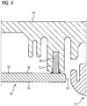
- FIG. 4 shows a section of the in FIG. 2 illustrated inner housing hub 24 in the region of the mounting portion 28 in a longitudinal section.
- the fastening section 28 For the sake of simplicity, only the main body 30 with the web-shaped projection 38 is illustrated by the fastening section 28. (The on the hot side 34 arranged heat shield 44 was omitted in the figure). Opposite the hot side 34 extends the cold side 36 of the main body 30, wherein in the region of the end face 50 of the main body 30 of the web-shaped projection 38 is disposed on the cold side 36.
- the web-shaped projection 38 is arranged in a groove 52 running in the fastening component 48.
- the groove 52 and the web-shaped projection 38 form a tongue-and-groove connection which fixes the position of the fastening section 28 and thus the position of the inner housing hub 24 in a turbine inlet region 54, so that the inner housing hub 24 is arranged with an end face 50 in a turbine inlet region 54 is.
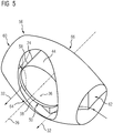
- FIG. 5 shows an inner housing 56 of a gas turbine with a centrally located in the inner housing according to the invention inner housing hub 58.
- the inner housing hub 58 encloses a along the central axis 26 extending gas turbine shaft (not shown).
- the inner housing 56 has two inputs 60 and 62 and an annular output 64. At the back 66, the inner housing is closed.
- the inputs 60 and 62 can each be arranged on a combustion chamber outlet of a combustion chamber (not shown).
- the output 64 is at a turbine inlet region (not shown) angordenbar.
- the inner housing 56 serves for deflecting the hot gases emerging from the two combustion chambers along the hot gas path 32 schematically illustrated by an arrow.
- the hot gases flow along the inner housing hub 58 surrounded by a heat protection 44 through the inner housing.
- the inner housing hub 58 For attachment of the inner housing, inter alia, the inner housing hub 58 in the region of its end face 50 by means of the web-shaped, on the cold side 36 circumferentially arranged projection 38 on a surrounding of the hub fastening component (not shown) attached. So that the cold projection 38 does not contract the inner housing hub during operation, the inner housing hub 58 is designed according to the invention. This protects in particular the heat protection 44 from a Chipping and thus the underlying body of the mounting portion from premature wear.
Landscapes
- Engineering & Computer Science (AREA)
- Mechanical Engineering (AREA)
- General Engineering & Computer Science (AREA)
- Turbine Rotor Nozzle Sealing (AREA)
Description
- Die Erfindung bezieht sich auf eine Innengehäusenabe für eine Gasturbine. Die Innengehäusenabe ist in der Gasturbine um eine Gasturbinenwelle herum anordenbar und dient als Bestandteil eines Innengehäuses zusammen mit dem Innengehäuse dem Umlenken von aus Brennkammern austretenden Heißgasen auf einen in Richtung der Gasturbinenwelle angeordneten Turbineneintrittsbereich. Die Innengehäusenabe wird somit auf ihrer von der Gasturbinenwelle abgewandten Seite von den umzulenkenden Heißgasen angeströmt.
- Die Innengehäusenabe umfasst mindestens einen im Wesentlichen zylindermantelförmigen Befestigungsabschnitt mit einem zylindermantelförmigen Grundkörper, an welchem die Innengehäusenabe an einer geeignet ausgebildeten Befestigungskomponente der Gasturbine befestigt ist. Der Begriff zylindermantelförmig ist hierbei nicht im streng mathematischen Sinne zu verstehen. Der Befestigungsabschnitt bzw. der Grundkörper sind als rohrförmige Wand ausgebildet. Der Begriff zylindermantelförmig bezieht sich somit nur auf die umlaufende Form der Wand und nicht auf die Dicke der Wand. Die Befestigungskomponente kann beispielsweise ein indirekt an einem Außengehäuse der Gasturbine befestigtes Bauteil sein. Der Grundkörper der Innengehäusenabe weist eine einem Heißgaspfad zugewandten Heißseite und eine dem Heißgaspfad abgewandten Kaltseite auf. Die Kaltseite ist somit der Gasturbinenwelle zugewandt. Zur Befestigung der Innengehäusenabe ist an dem zylindermantelförmigen Grundkörper mindestens ein stegförmiger Vorsprung angeordnet, der sich entlang der Kaltseite erstreckt und an der Kaltseite angeordnet ist.
- Derartige Befestigungen sind insbesondere bei Komponenten des Brennkammergehäuses oder des Innengehäuses von Gasturbinen mit Silobrennkammern üblich.
- Der stegförmige Vorsprung ist hierbei Teil einer Nut-Feder-Verbindung zwischen dem zylindermantelförmigen Grundkörper und der Befestigungskomponente. Der stegförmige Vorsprung kann beispielsweise die Feder ausbilden und zur Befestigung in einer an der Befestigungskomponente verlaufenden Nut angeordnet werden. Der stegförmige Vorsprung könnte aber auch die Nut der Nut-Feder-Verbindung ausbilden, indem eine Nut in seiner Oberseite verläuft, die mit einer entsprechend ausgebildeten Feder der Befestigungskomponente korrespondiert. Aufgrund der betriebsgemäßen Temperaturunterschiede zwischen der Heißseite und der Kaltseite unterliegt die gattungsgemäße Innengehäusenabe, insbesondere im Bereich des Befestigungsabschnitts, hohen thermischen Spannungen. Diese thermischen Spannungen können sich vom Grundkörper auf einen auf der Heißseite angeordneten Hitzeschutz übertragen. Bei dem Hitzeschutz kann es sich beispielsweise um eine Wärmedämmschicht, insbesondere um eine keramische Schutzschicht handeln. Dies führt insbesondere im Bereich des Befestigungsabschnitts zu einem hohen Verschleiß der Innengehäusenabe aufgrund von Start-Stop-getriebenen Ermüdungsrissen mit anschließendem Risswachstum und Abplatzen des Hitzeschutzs von der Heißseite des Grundkörpers. Die Patentschrift
EP-1744016 offenbart ein Beispiel einer Innengehäusenabe. Der Erfindung liegt die Aufgabe zugrunde, eine Gasturbine mit einer Innengehäusenabe der eingangs genannten Art anzugeben, welche einem reduzierten Verschleiß unterliegt.
Die Aufgabe wird erfindungsgemäß bei einer Gasturbine mit einer Innengehäusenabe der eingangs genannten Art dadurch gelöst, dass der stegförmige Vorsprung aus einem ersten Material und der Grundkörper aus einem zweiten Material besteht, wobei das erste Material einen größeren Wärmeausdehnungskoeffizienten aufweist als das zweite Material, so dass in mindestens einem Betriebszustand der Gasturbine die thermisch induzierten Spannungen im Bereich des Befestigungsabschnitts gegenüber einer aus dem zweiten Material bestehenden einstückigen Ausbildung des Grundkörpers und des stegförmigen Vorsprungs reduziert sind. - Erfindungsgemäß wird somit zur Reduzierung des Verschleiß nicht der Wärmeschutz auf der Heißseite verbessert, sondern zur Reduzierung thermischer Spannungen die Ausbildung des Grundkörpers verbessert. Dieser ist erfindungsgemäß nicht mehr einstückig mit dem Vorsprung ausgebildet. Vorsprung und Grundkörper werden aus unterschiedlichen Materialien hergestellt. Beispielsweise können die beiden getrennt hergestellt werden und durch Schweißen oder Löten aneinandergefügt werden. Der von dem zylindermantelförmigen Grundkörper abstehende stegförmige Vorsprung, der somit kälter als der restliche Grundkörper ist, wird dabei aus einem Material mit höherem Wärmeausdehnungskoeffizient gefertigt als der wärmere Grundkörper. Aufgrund des größeren Wärmeausdehnungskoeffizienten zieht der Vorsprung den Grundkörper nicht mehr oder nicht mehr so stark zusammen. Allerdings sollte der Wärmeausdehnungskoeffizient auch nicht so groß gewählt werden, dass der kältere Vorsprung sich im Betrieb trotz geringerer Temperaturdifferenz im Bereich des Vorsprungs wesentlich stärker ausdehnt als der Grundkörper. Deshalb wird das erste Material und das zweite Material derart gewählt, dass sie die Anforderungen an die Innengehäusenabe und die Befestigung erfüllen und erfindungsgemäß die unterschiedlichen Wärmeausdehnungskoeffizienten derart sind, dass die thermisch induzierten Spannungen im Bereich des Befestigungsabschnitts gegenüber einer aus dem zweiten Material bestehenden einstückigen Ausbildung des Grundkörpers und des stegförmigen Vorsprungs reduziert sind. Der Grundkörper kann einen oder mehrere erfindungsgemäß ausgebildete stegförmige Vorsprünge umfassen.
- Die Innengehäusenabe ist zwischen Heiß- und Kaltseite des Grundkörpers hohen Temperaturunterschieden ausgesetzt, so dass die erfindungsgemäße Ausbildung des Befestigungsabschnitts der Innengehäusenabe eine wesentliche Verlängerung der Lebensdauer der Innengehäusenabe ermöglicht.
- Vorteilhafterweise kann vorgesehen sein, dass die Innengehäusenabe zu ihrer Befestigung in der Gasturbine derart an einer Befestigungskomponente befestigbar ist, dass der stegförmige Vorsprung in einer von der Befestigungskomponente umfassten Nut anordenbar ist.
- Der stegförmige Vorsprung bildet somit die Feder der Nut-Feder-Verbindung aus.
Der Grundkörper kann einen oder mehrere erfindungsgemäß ausgebildete stegförmige Vorsprünge umfassen. Diese können beispielsweise entlang ihrer Längserstreckung aneinandergereiht an der Kaltseite angeordnet sein und einen gemeinsamen, unterteilten Steg ausbilden, der in einer Nut an der Befestigungskomponente angeordnet werden kann. - Es kann auch als vorteilhaft angesehen werden, dass der Befestigungsabschnitt ein um eine Mittelachse herum angeordnete Gehäusewand ist, welche von dem Heißgaspfad umströmt wird, so dass die Heißseite des Grundkörpers von der Mittelachse abgewandt ist.
- Ein als Gehäusewand ausgebildeter Befestigungsabschnitt ist aufgrund seiner geringen Ausdehnung senkrecht zur Wand besonders anfällig für ein durch thermische Spannungen hervorgerufenes Verbiegen. Der Verschleiß derartiger Gasturbinenkomponenten kann mit der Erfindung besonders stark reduziert werden.
- Eine weitere vorteilhafte Ausgestaltung der Erfindung kann vorsehen, dass die Innengehäusenabe mindestens im Bereich des Befestigungsabschnitts im Wesentlichen Zylindermantelförmig ausgebildet ist und der mindestens eine stegförmige Vorsprung entlang einer kreisförmigen Umfangslinie an dem Grundkörper angeordnet ist, so dass ein durchgehender oder segmentförmig unterteilter oder unterbrochener ringförmiger Steg an der Kaltseite angeordnet ist.
- Es kann auch als vorteilhaft angesehen sein, dass die Innengehäusenabe mit einer Stirnseite in einem Turbineneintrittsbereich anordenbar ist, wobei der Befestigungsabschnitt im Bereich der Stirnseite angeordnet ist.
- Weitere zweckmäßige Ausgestaltungen und Vorteile der Erfindung sind Gegenstand der Beschreibung von Ausführungsbeispielsen der Erfindung unter Bezug auf die Figur der Zeichnung, wobei gleiche Bezugszeichen auf gleich wirkende Bauteile verweisen.
- Dabei zeigt die
-
Fig. 1 schematisch einen Längsschnitt durch eine Gasturbine nach dem Stand der Technik, -
Fig. 2 schematisch eine Innengehäusenabe gemäß einem Ausführungsbeispiel der Erfindung in einer perspektivischen Ansicht, -
Fig. 3 schematisch einen Ausschnitt der inFigur 2 dargestellten Innengehäusenabe in einem Längsschnitt, -
Fig. 4 schematisch einen Ausschnitt der inFigur 2 dargestellten Innengehäusenabe mit am Vorsprung angeordneter Befestigungskomponente in einem Längsschnitt, und -
Fig.5 schematisch ein Innengehäuse einer Gasturbine mit Innengehäusenabe, welche gemäßFigur 2 ausgebildet ist in einer perspektivischen Ansicht. - Die
Figur 1 zeigt eine schematische Schnittansicht einer Gasturbine 1 nach dem Stand der Technik. Die Gasturbine 1 weist im Inneren einen um eine Rotationsachse 2 drehgelagerten Rotor 3 mit einer Welle 4 auf, der auch als Turbinenläufer bezeichnet wird. Entlang des Rotors 3 folgen aufeinander ein Ansauggehäuse 6, ein Verdichter 8, ein Verbrennungssystem 9 mit mindestens einer Brennkammer 10, eine Turbine 14 und ein Abgasgehäuse 15. Die eine oder mehreren Brennkammern 10 umfassen jeweils eine Brenneranordnung 11 und ein Gehäuse 12, welches zum Schutz vor Heißgasen mit einem Hitzeschild 20 ausgekleidet ist. Die mindestens eine Brennkammer 10 kann eine Ringbrennkammer sein. Die Gasturbine kann alternativ auch eine oder mehrere Rohrbrennkammern oder Silobrennkammern umfassen. - Das Verbrennungssystem 9 kommuniziert mit einem beispielsweise ringförmigen Heißgaskanal. Dort bilden mehrere hintereinander geschaltete Turbinenstufen die Turbine 14. Jede Turbinenstufe ist aus Schaufelringen gebildet. In Strömungsrichtung eines Arbeitsmediums gesehen folgt im Heißkanal einer aus Leitschaufeln 17 gebildeten Reihe eine aus Laufschaufeln 18 gebildete Reihe. Die Leitschaufeln 17 sind dabei an einem Innengehäuse eines Stators 19 befestigt, wohingegen die Laufschaufeln 18 einer Reihe beispielsweise mittels einer Turbinenscheibe am Rotor 3 angebracht sind. An dem Rotor 3 angekoppelt ist beispielsweise ein Generator (nicht dargestellt).
- Während des Betriebes der Gasturbine wird vom Verdichter 8 durch das Ansauggehäuse 6 Luft angesaugt und verdichtet. Die am turbinenseitigen Ende des Verdichters 8 bereitgestellte verdichtete Luft wird zu dem Verbrennungssystem 9 geführt und dort im Bereich der Brenneranordnung 11 mit einem Brennstoff vermischt. Das Gemisch wird dann mit Hilfe der Brenneranordnung 11 unter Bildung eines Arbeitsgasstromes im Verbrennungssystem 9 verbrannt. Von dort strömt der Arbeitsgasstrom entlang des Heißgaskanals an den Leitschaufeln 17 und den Laufschaufeln 18 vorbei. An den Laufschaufeln 18 entspannt sich der Arbeitsgasstrom impulsübertragend, so dass die Laufschaufeln 18 den Rotor 3 antreiben und dieser den an ihn angekoppelten Generator (nicht dargestellt).
- Die
Figur 2 zeigt eine erfindungsgemäße Innengehäusenabe 24 für eine Gasturbine gemäß einem Ausführungsbeispiel in einer perspektivischen Ansicht. Die Innengehäusenabe 24 ist zylindermantelförmig ausgebildet mit einer Mittelachse 26. Der eine Endbereich der Innengehäusenabe bildet einen Befestigungsabschnitt 28 aus. Der zylindermantelförmige Befestigungsabschnitt 28 umfasst einen zylindermantelförmigen Grundkörper 30, der eine einem Heißgaspfad (der schematisch mit dem Pfeil 32 verdeutlicht ist) zugewandte Heißseite 34 und eine dem Heißgaspfad abgewandte Kaltseite 36 umfasst. Die Heißseite 34 kann mit einem Wärmeschutz beschichtet sein (nicht dargestellt). An dem Grundkörper 30 ist zur Befestigung der Innengehäusenabe 24 ein stegförmiger Vorsprung 38 angeordnet. - Der stegförmige Vorsprung 38 erstreckt sich entlang einer kreisförmigen Umfangslinie entlang der Kaltseite 36 des Grundkörpers und ist an der Kaltseite des zylindermantelförmigen Grundkörpers 30 angeordnet, so dass er als ein umlaufender ringförmiger Steg an der Kaltseite 36 angeordnet ist. Zur Befestigung der Innengehäusenabe 24 an einer Befestigungskomponente (nicht dargestellt) wird der ringförmige Vorsprung 38 in einer in der Befestigungskomponente verlaufenden ringförmigen Nut (nicht dargestellt) angeordnet. Hierzu kann die Innengehäusenabe 24 aus zwei Halbschalen aufgebaut sein, die zunächst getrennt an der Befestigungskomponente (nicht dargestellt) zur Anlage gebracht und dann zusammengefügt werden. In diesem Fall ist der umlaufende stegförmige Vorsprung 38 segmentförmig unterteilt.
- Bei dem dargestellten Ausführungsbeispiel ist der Befestigungsabschnitt 28 ein um eine Mittelachse 26 herum angeordnete Gehäusewand 40, welche von dem Heißgaspfad 32 umströmt wird, so dass die Heißseite 34 von der Mittelachse 26 abgewandt ist. Die gesamte Innengehäusenabe 24 kann, bis auf den stegförmigen Vorsprung, dem Aufbau des Befestigungsabschnitts entsprechen, so dass die Unterteilung der Innengehäusenabe in einen Befestigungsabschnitt bis zur Linie 42 bei dem vorliegenden Ausführungsbeispiel in gewisser Weise frei gewählt werden kann.
- Die
Figur 3 zeigt einen Ausschnitt der inFigur 2 dargestellten Innengehäusenabe in einem Längsschnitt im Bereich des Befestigungsabschnitts 28. Der in Form einer Gehäusewand 40 ausgebildete Befestigungsabschnitt 28 umfasst einen zylindermantelförmigen Grundkörper 30 mit einer Heißseite 34 und einer Kaltseite 36. Die Heißseite ist mit einem Hitzeschutz 44 beschichtet. An der Kaltseite 36 ist ein stegförmiger Vorsprung 38 angeordnet, dessen Querschnitt 46 in der Figur zu erkennen ist. Erfindungsgemäß besteht der stegförmige Vorsprung 38 aus einem ersten Material und der Grundkörper 30 aus einem zweiten Material, wobei das erste Material einen größeren Wärmeausdehnungskoeffizienten aufweist als das zweite Material, so dass in mindestens einem Betriebszustand der Gasturbine die thermisch induzierten Spannungen im Bereich des Befestigungsabschnitts 28 gegenüber einer aus dem zweiten Material bestehenden einstückigen Ausbildung des Grundkörpers 30 und des stegförmigen Vorsprungs 38 reduziert sind. Besonders um den Übergangsbereich von Grundkörper und stegförmigem Vorsprung 38 herum werden im Betrieb der einstückigen, aus dem Stand der Technik bekannten Ausbildung des Befestigungsabschnitts, hohe thermische Spannungen erzeugt. - Die
Figur 4 zeigt einen Ausschnitt der inFigur 2 dargestellten Innengehäusenabe 24 im Bereich des Befestigungsabschnitts 28 in einem Längsschnitt. Es ist der Einfachheit halber vom Befestigungsabschnitt 28 nur der Grundkörper 30 mit dem stegförmigen Vorsprung 38 dargestellt. (Der auf der Heißseite 34 angeordnete Hitzeschutz 44 wurde in der Figur weggelassen). Gegenüberliegend der Heißseite 34 verläuft die Kaltseite 36 des Grundkörpers 30, wobei im Bereich der Stirnseite 50 des Grundkörpers 30 der stegförmige Vorsprung 38 an der Kaltseite 36 angeordnet ist. Zur Befestigung des Befestigungsabschnitts 28 an einer Befestigungskomponente 48 ist der stegförmige Vorsprung 38 in einer in der Befestigungskomponente 48 verlaufenden Nut 52 angeordnet. Die Nut 52 und der stegförmige Vorsprung 38 bilden eine Nut-Feder-Verbindung aus, die die Lage des Befestigungsabschnitts 28 und damit die Lage der Innengehäusenabe 24 in einem Turbineneintrittsbereichs 54 fixiert, so dass die Innengehäusenabe 24 mit einer Stirnseite 50 in einem Turbineneintrittsbereich 54 angeordnet ist. - Die
Figur 5 zeigt ein Innengehäuse 56 einer Gasturbine mit einer zentral im Innengehäuse angeordneten erfindungsgemäßen Innengehäusenabe 58. Die Innengehäusenabe 58 umschließt eine sich entlang der Mittelachse 26 erstreckende Gasturbinenwelle (nicht dargestellt). Das Innengehäuse 56 weist zwei Eingänge 60 und 62 und einen ringförmigen Ausgang 64 auf. An der Rückseite 66 ist das Innengehäuse geschlossen. Die Eingänge 60 und 62 sind jeweils an einen Brennkammerausgang einer Brennkammer(nicht dargestellt) anordenbar. Der Ausgang 64 ist an einem Turbineneintrittsbereich (nicht dargestellt) angordenbar. Das Innengehäuse 56 dient dem Umlenken der aus den beiden Brennkammern austretenden Heißgase entlang des mit einem Pfeil schematisch verdeutlichen Heißgaspfads 32. Dabei strömen die Heißgase u.a. entlang der mit einem Hitzeschutz 44 ummantelte Innengehäusenabe 58 durch das Innengehäuse hindurch. Zur Befestigung des Innengehäuses ist u.a. die Innengehäusenabe 58 im Bereich ihrer Stirnseite 50 mittels des stegförmigen, an der Kaltseite 36 umlaufend angeordneten Vorsprungs 38 an einer von der Nabe umgebenden Befestigungskomponente (nicht dargestellt) befestigt. Damit der kalte Vorsprung 38 die Innengehäusenabe im Betrieb nicht zusammenzieht, ist die Innengehäusenabe 58 erfindungsgemäß ausgebildet. Dies schützt insbesondere den Hitzeschutz 44 vor einem Abplatzen und somit den darunter angeordneten Grundkörper des Befestigungsabschnitts vor einem vorzeitigen Verschleiß.
Claims (5)
- Gasturbine (1) mit einem Innengehäuse (56), welches (56) dem Umlenken von aus Brennkammern austretenden Heißgasen auf einen in Richtung der Gasturbinenwelle angeordneten Turbineneintrittsbereich (54) dient und eine Innengehäusenabe (24,58) umfasst, wobei die Innengehäusenabe (24,58) mindestens einen im Wesentlichen zylindermantelförmigen Befestigungsabschnitt (28) umfasst mit einem zylindermantelförmigen Grundkörper (30), welcher (30) eine einem Heißgaspfad (32) zugewandten Heißseite (34) und eine dem Heißgaspfad abgewandten Kaltseite (36) aufweist, und mit mindestens ein stegförmiger Vorsprung (38), welcher (38) an dem Grundkörper (30) an der Kaltseite zur Befestigung der Innengehäusenabe (24, 58) sich entlang der Kaltseite (36) erstreckend angeordnet ist,
dadurch gekennzeichnet,
dass der stegförmige Vorsprung (38) aus einem ersten Material und der Grundkörper (30) aus einem zweiten Material besteht, wobei das erste Material einen größeren Wärmeausdehnungskoeffizienten als das zweite Material aufweist, so dass in mindestens einem Betriebszustand der Gasturbine die thermisch induzierten Spannungen im Bereich des Befestigungsabschnitts (28) gegenüber einer aus dem zweiten Material bestehenden einstückigen Ausbildung des Grundkörpers und des stegförmigen Vorsprungs reduziert sind. - Gasturbine (1) nach Anspruch 1,
dadurch gekennzeichnet,
dass die Innengehäusenabe (24, 58) zu ihrer Befestigung in der Gasturbine derart an einer Befestigungskomponente (48) befestigbar ist, dass der stegförmige Vorsprung (38) in einer von der Befestigungskomponente umfassten Nut (52) anordenbar ist. - Gasturbine (1) nach Anspruch 1 oder 2,
dadurch gekennzeichnet,
dass der Befestigungsabschnitt (28) ein um eine Mittelachse (26) herum angeordnete Gehäusewand (40) ist, welche von dem Heißgaspfad (32) umströmt wird, so dass die Heißseite (34) von der Mittelachse (26) abgewandt ist. - Gasturbine (1) nach einem der Ansprüche 1 bis 3,
dadurch gekennzeichnet,
dass die Innengehäusenabe mindestens im Bereich des Befestigungsabschnitts (28) im Wesentlichen Zylindermantelförmig ausgebildet ist und der mindestens eine stegförmige Vorsprung (38) entlang einer kreisförmigen Umfangslinie an dem Grundkörper angeordnet ist, so dass ein durchgehender oder segmentförmig unterteilter oder unterbrochener ringförmiger Steg an der Kaltseite angeordnet ist. - Gasturbine (1) nach einem der Ansprüche 1 bis 4,
dadurch gekennzeichnet,
dass die Innengehäusenabe (24, 58) mit einer Stirnseite (50) in einem Turbineneintrittsbereich (54) anordenbar ist, wobei der Befestigungsabschnitt (28) im Bereich der Stirnseite (50) angeordnet ist.
Applications Claiming Priority (2)
| Application Number | Priority Date | Filing Date | Title |
|---|---|---|---|
| DE102013219612 | 2013-09-27 | ||
| PCT/EP2014/070483 WO2015044266A1 (de) | 2013-09-27 | 2014-09-25 | Innengehäusenabe für eine gasturbine |
Publications (2)
| Publication Number | Publication Date |
|---|---|
| EP3008293A1 EP3008293A1 (de) | 2016-04-20 |
| EP3008293B1 true EP3008293B1 (de) | 2017-11-29 |
Family
ID=51660455
Family Applications (1)
| Application Number | Title | Priority Date | Filing Date |
|---|---|---|---|
| EP14780800.0A Not-in-force EP3008293B1 (de) | 2013-09-27 | 2014-09-25 | Innengehäusenabe für eine gasturbine |
Country Status (4)
| Country | Link |
|---|---|
| US (1) | US20160208628A1 (de) |
| EP (1) | EP3008293B1 (de) |
| CN (1) | CN105579669B (de) |
| WO (1) | WO2015044266A1 (de) |
Family Cites Families (5)
| Publication number | Priority date | Publication date | Assignee | Title |
|---|---|---|---|---|
| EP1118806A1 (de) * | 2000-01-20 | 2001-07-25 | Siemens Aktiengesellschaft | Thermisch belastbare Wand und Verfahren zur Abdichtung eines Spaltes in einer thermisch belasteten Wand |
| DE50112597D1 (de) * | 2001-04-12 | 2007-07-19 | Siemens Ag | Gasturbine mit axial verschiebbaren Gehäuseteilen |
| US6910853B2 (en) * | 2002-11-27 | 2005-06-28 | General Electric Company | Structures for attaching or sealing a space between components having different coefficients or rates of thermal expansion |
| US7000406B2 (en) * | 2003-12-03 | 2006-02-21 | Pratt & Whitney Canada Corp. | Gas turbine combustor sliding joint |
| EP1744016A1 (de) * | 2005-07-11 | 2007-01-17 | Siemens Aktiengesellschaft | Heissgasführendes Gehäuseelement, Wellenschutzmantel und Gasturbinenanlage |
-
2014
- 2014-09-25 US US15/023,395 patent/US20160208628A1/en not_active Abandoned
- 2014-09-25 WO PCT/EP2014/070483 patent/WO2015044266A1/de not_active Ceased
- 2014-09-25 EP EP14780800.0A patent/EP3008293B1/de not_active Not-in-force
- 2014-09-25 CN CN201480052858.0A patent/CN105579669B/zh not_active Expired - Fee Related
Also Published As
| Publication number | Publication date |
|---|---|
| CN105579669B (zh) | 2017-07-07 |
| CN105579669A (zh) | 2016-05-11 |
| US20160208628A1 (en) | 2016-07-21 |
| EP3008293A1 (de) | 2016-04-20 |
| WO2015044266A1 (de) | 2015-04-02 |
Similar Documents
| Publication | Publication Date | Title |
|---|---|---|
| DE3713923C2 (de) | Kühlluft-Übertragungsvorrichtung | |
| EP2179143B1 (de) | Spaltkühlung zwischen brennkammerwand und turbinenwand einer gasturbinenanlage | |
| DE2943464A1 (de) | Dichtungsvorrichtung fuer ein gasturbinentriebwerk | |
| EP3121371B1 (de) | Turbine mit gekühlten turbinenleitschaufeln | |
| EP3017253B1 (de) | Keramisches hitzeschild für eine gasturbinenbrennkammer, brennkammer für eine gasturbine und verfahren | |
| EP2728122B1 (de) | Dichtungsträgerfixierung für eine Strömungsmaschine | |
| EP2647795A1 (de) | Dichtungssystem für eine Strömungsmaschine | |
| EP2084368B1 (de) | Turbinenschaufel | |
| EP3064706A1 (de) | Leitschaufelreihe für eine axial durchströmte Strömungsmaschine | |
| CH709266B1 (de) | Turbinenschaufel und Verfahren zum Auswuchten eines Spitzendeckbandes einer Turbinenschaufel und Gasturbine. | |
| EP0999349B1 (de) | Axialturbine | |
| EP2411631B1 (de) | Dichtplatte und Laufschaufelsystem | |
| WO2009109430A1 (de) | Dichtungsanordnung und gasturbine | |
| EP1904717B1 (de) | HEIßGASFÜHRENDES GEHÄUSEELEMENT, WELLENSCHUTZMANTEL UND GASTURBINENANLAGE | |
| WO2017025284A1 (de) | Brennkammer für eine gasturbine und hitzeschildelement zum auskleiden einer derartigen brennkammer | |
| EP3004741B1 (de) | Rohrbrennkammer mit einem flammrohr-endbereich und gasturbine | |
| EP2725203A1 (de) | Kühlluftführung in einer Gehäusestruktur einer Strömungsmaschine | |
| EP1429077B1 (de) | Gasturbine | |
| EP3921577B1 (de) | Rohrbrennkammersystem und gasturbinenanlage mit einem solchen rohrbrennkammersystem | |
| EP1783325B1 (de) | Befestigungsanordnung eines Rohres an einer Umfangsfläche | |
| DE102005045255A1 (de) | Verbesserter Verdichter in Axialbauart | |
| DE3519646A1 (de) | Umlaufende labyrinthdichtung | |
| EP3008293A1 (de) | Innengehäusenabe für eine gasturbine | |
| WO2003021149A1 (de) | Brennkammeranordnung | |
| EP1731715A1 (de) | Übergangsbereich zwischen einer Brennkammer und einer Turbineneinheit |
Legal Events
| Date | Code | Title | Description |
|---|---|---|---|
| PUAI | Public reference made under article 153(3) epc to a published international application that has entered the european phase |
Free format text: ORIGINAL CODE: 0009012 |
|
| 17P | Request for examination filed |
Effective date: 20160111 |
|
| AK | Designated contracting states |
Kind code of ref document: A1 Designated state(s): AL AT BE BG CH CY CZ DE DK EE ES FI FR GB GR HR HU IE IS IT LI LT LU LV MC MK MT NL NO PL PT RO RS SE SI SK SM TR |
|
| AX | Request for extension of the european patent |
Extension state: BA ME |
|
| DAX | Request for extension of the european patent (deleted) | ||
| 17Q | First examination report despatched |
Effective date: 20170214 |
|
| GRAP | Despatch of communication of intention to grant a patent |
Free format text: ORIGINAL CODE: EPIDOSNIGR1 |
|
| INTG | Intention to grant announced |
Effective date: 20170705 |
|
| RAP1 | Party data changed (applicant data changed or rights of an application transferred) |
Owner name: SIEMENS AKTIENGESELLSCHAFT |
|
| GRAS | Grant fee paid |
Free format text: ORIGINAL CODE: EPIDOSNIGR3 |
|
| GRAA | (expected) grant |
Free format text: ORIGINAL CODE: 0009210 |
|
| AK | Designated contracting states |
Kind code of ref document: B1 Designated state(s): AL AT BE BG CH CY CZ DE DK EE ES FI FR GB GR HR HU IE IS IT LI LT LU LV MC MK MT NL NO PL PT RO RS SE SI SK SM TR |
|
| REG | Reference to a national code |
Ref country code: CH Ref legal event code: EP |
|
| REG | Reference to a national code |
Ref country code: AT Ref legal event code: REF Ref document number: 950587 Country of ref document: AT Kind code of ref document: T Effective date: 20171215 |
|
| REG | Reference to a national code |
Ref country code: IE Ref legal event code: FG4D Free format text: LANGUAGE OF EP DOCUMENT: GERMAN |
|
| REG | Reference to a national code |
Ref country code: DE Ref legal event code: R096 Ref document number: 502014006426 Country of ref document: DE |
|
| REG | Reference to a national code |
Ref country code: NL Ref legal event code: MP Effective date: 20171129 |
|
| REG | Reference to a national code |
Ref country code: LT Ref legal event code: MG4D |
|
| PG25 | Lapsed in a contracting state [announced via postgrant information from national office to epo] |
Ref country code: NO Free format text: LAPSE BECAUSE OF FAILURE TO SUBMIT A TRANSLATION OF THE DESCRIPTION OR TO PAY THE FEE WITHIN THE PRESCRIBED TIME-LIMIT Effective date: 20180228 Ref country code: LT Free format text: LAPSE BECAUSE OF FAILURE TO SUBMIT A TRANSLATION OF THE DESCRIPTION OR TO PAY THE FEE WITHIN THE PRESCRIBED TIME-LIMIT Effective date: 20171129 Ref country code: SE Free format text: LAPSE BECAUSE OF FAILURE TO SUBMIT A TRANSLATION OF THE DESCRIPTION OR TO PAY THE FEE WITHIN THE PRESCRIBED TIME-LIMIT Effective date: 20171129 Ref country code: FI Free format text: LAPSE BECAUSE OF FAILURE TO SUBMIT A TRANSLATION OF THE DESCRIPTION OR TO PAY THE FEE WITHIN THE PRESCRIBED TIME-LIMIT Effective date: 20171129 Ref country code: ES Free format text: LAPSE BECAUSE OF FAILURE TO SUBMIT A TRANSLATION OF THE DESCRIPTION OR TO PAY THE FEE WITHIN THE PRESCRIBED TIME-LIMIT Effective date: 20171129 |
|
| PG25 | Lapsed in a contracting state [announced via postgrant information from national office to epo] |
Ref country code: HR Free format text: LAPSE BECAUSE OF FAILURE TO SUBMIT A TRANSLATION OF THE DESCRIPTION OR TO PAY THE FEE WITHIN THE PRESCRIBED TIME-LIMIT Effective date: 20171129 Ref country code: LV Free format text: LAPSE BECAUSE OF FAILURE TO SUBMIT A TRANSLATION OF THE DESCRIPTION OR TO PAY THE FEE WITHIN THE PRESCRIBED TIME-LIMIT Effective date: 20171129 Ref country code: GR Free format text: LAPSE BECAUSE OF FAILURE TO SUBMIT A TRANSLATION OF THE DESCRIPTION OR TO PAY THE FEE WITHIN THE PRESCRIBED TIME-LIMIT Effective date: 20180301 Ref country code: RS Free format text: LAPSE BECAUSE OF FAILURE TO SUBMIT A TRANSLATION OF THE DESCRIPTION OR TO PAY THE FEE WITHIN THE PRESCRIBED TIME-LIMIT Effective date: 20171129 Ref country code: BG Free format text: LAPSE BECAUSE OF FAILURE TO SUBMIT A TRANSLATION OF THE DESCRIPTION OR TO PAY THE FEE WITHIN THE PRESCRIBED TIME-LIMIT Effective date: 20180228 |
|
| PG25 | Lapsed in a contracting state [announced via postgrant information from national office to epo] |
Ref country code: NL Free format text: LAPSE BECAUSE OF FAILURE TO SUBMIT A TRANSLATION OF THE DESCRIPTION OR TO PAY THE FEE WITHIN THE PRESCRIBED TIME-LIMIT Effective date: 20171129 |
|
| PG25 | Lapsed in a contracting state [announced via postgrant information from national office to epo] |
Ref country code: EE Free format text: LAPSE BECAUSE OF FAILURE TO SUBMIT A TRANSLATION OF THE DESCRIPTION OR TO PAY THE FEE WITHIN THE PRESCRIBED TIME-LIMIT Effective date: 20171129 Ref country code: CY Free format text: LAPSE BECAUSE OF FAILURE TO SUBMIT A TRANSLATION OF THE DESCRIPTION OR TO PAY THE FEE WITHIN THE PRESCRIBED TIME-LIMIT Effective date: 20171129 Ref country code: DK Free format text: LAPSE BECAUSE OF FAILURE TO SUBMIT A TRANSLATION OF THE DESCRIPTION OR TO PAY THE FEE WITHIN THE PRESCRIBED TIME-LIMIT Effective date: 20171129 Ref country code: CZ Free format text: LAPSE BECAUSE OF FAILURE TO SUBMIT A TRANSLATION OF THE DESCRIPTION OR TO PAY THE FEE WITHIN THE PRESCRIBED TIME-LIMIT Effective date: 20171129 Ref country code: SK Free format text: LAPSE BECAUSE OF FAILURE TO SUBMIT A TRANSLATION OF THE DESCRIPTION OR TO PAY THE FEE WITHIN THE PRESCRIBED TIME-LIMIT Effective date: 20171129 |
|
| REG | Reference to a national code |
Ref country code: DE Ref legal event code: R097 Ref document number: 502014006426 Country of ref document: DE |
|
| PG25 | Lapsed in a contracting state [announced via postgrant information from national office to epo] |
Ref country code: SM Free format text: LAPSE BECAUSE OF FAILURE TO SUBMIT A TRANSLATION OF THE DESCRIPTION OR TO PAY THE FEE WITHIN THE PRESCRIBED TIME-LIMIT Effective date: 20171129 Ref country code: RO Free format text: LAPSE BECAUSE OF FAILURE TO SUBMIT A TRANSLATION OF THE DESCRIPTION OR TO PAY THE FEE WITHIN THE PRESCRIBED TIME-LIMIT Effective date: 20171129 Ref country code: PL Free format text: LAPSE BECAUSE OF FAILURE TO SUBMIT A TRANSLATION OF THE DESCRIPTION OR TO PAY THE FEE WITHIN THE PRESCRIBED TIME-LIMIT Effective date: 20171129 |
|
| PG25 | Lapsed in a contracting state [announced via postgrant information from national office to epo] |
Ref country code: MT Free format text: LAPSE BECAUSE OF FAILURE TO SUBMIT A TRANSLATION OF THE DESCRIPTION OR TO PAY THE FEE WITHIN THE PRESCRIBED TIME-LIMIT Effective date: 20171129 |
|
| PLBE | No opposition filed within time limit |
Free format text: ORIGINAL CODE: 0009261 |
|
| STAA | Information on the status of an ep patent application or granted ep patent |
Free format text: STATUS: NO OPPOSITION FILED WITHIN TIME LIMIT |
|
| PGFP | Annual fee paid to national office [announced via postgrant information from national office to epo] |
Ref country code: IT Payment date: 20180926 Year of fee payment: 5 |
|
| 26N | No opposition filed |
Effective date: 20180830 |
|
| PG25 | Lapsed in a contracting state [announced via postgrant information from national office to epo] |
Ref country code: SI Free format text: LAPSE BECAUSE OF FAILURE TO SUBMIT A TRANSLATION OF THE DESCRIPTION OR TO PAY THE FEE WITHIN THE PRESCRIBED TIME-LIMIT Effective date: 20171129 |
|
| PGFP | Annual fee paid to national office [announced via postgrant information from national office to epo] |
Ref country code: DE Payment date: 20181119 Year of fee payment: 5 |
|
| PG25 | Lapsed in a contracting state [announced via postgrant information from national office to epo] |
Ref country code: MC Free format text: LAPSE BECAUSE OF FAILURE TO SUBMIT A TRANSLATION OF THE DESCRIPTION OR TO PAY THE FEE WITHIN THE PRESCRIBED TIME-LIMIT Effective date: 20171129 |
|
| REG | Reference to a national code |
Ref country code: CH Ref legal event code: PL |
|
| GBPC | Gb: european patent ceased through non-payment of renewal fee |
Effective date: 20180925 |
|
| REG | Reference to a national code |
Ref country code: BE Ref legal event code: MM Effective date: 20180930 |
|
| REG | Reference to a national code |
Ref country code: IE Ref legal event code: MM4A |
|
| PG25 | Lapsed in a contracting state [announced via postgrant information from national office to epo] |
Ref country code: LU Free format text: LAPSE BECAUSE OF NON-PAYMENT OF DUE FEES Effective date: 20180925 |
|
| PG25 | Lapsed in a contracting state [announced via postgrant information from national office to epo] |
Ref country code: IE Free format text: LAPSE BECAUSE OF NON-PAYMENT OF DUE FEES Effective date: 20180925 |
|
| PG25 | Lapsed in a contracting state [announced via postgrant information from national office to epo] |
Ref country code: FR Free format text: LAPSE BECAUSE OF NON-PAYMENT OF DUE FEES Effective date: 20180930 Ref country code: CH Free format text: LAPSE BECAUSE OF NON-PAYMENT OF DUE FEES Effective date: 20180930 Ref country code: LI Free format text: LAPSE BECAUSE OF NON-PAYMENT OF DUE FEES Effective date: 20180930 Ref country code: BE Free format text: LAPSE BECAUSE OF NON-PAYMENT OF DUE FEES Effective date: 20180930 |
|
| PG25 | Lapsed in a contracting state [announced via postgrant information from national office to epo] |
Ref country code: GB Free format text: LAPSE BECAUSE OF NON-PAYMENT OF DUE FEES Effective date: 20180925 |
|
| PG25 | Lapsed in a contracting state [announced via postgrant information from national office to epo] |
Ref country code: TR Free format text: LAPSE BECAUSE OF FAILURE TO SUBMIT A TRANSLATION OF THE DESCRIPTION OR TO PAY THE FEE WITHIN THE PRESCRIBED TIME-LIMIT Effective date: 20171129 |
|
| REG | Reference to a national code |
Ref country code: DE Ref legal event code: R119 Ref document number: 502014006426 Country of ref document: DE |
|
| PG25 | Lapsed in a contracting state [announced via postgrant information from national office to epo] |
Ref country code: PT Free format text: LAPSE BECAUSE OF FAILURE TO SUBMIT A TRANSLATION OF THE DESCRIPTION OR TO PAY THE FEE WITHIN THE PRESCRIBED TIME-LIMIT Effective date: 20171129 |
|
| PG25 | Lapsed in a contracting state [announced via postgrant information from national office to epo] |
Ref country code: MK Free format text: LAPSE BECAUSE OF NON-PAYMENT OF DUE FEES Effective date: 20171129 Ref country code: HU Free format text: LAPSE BECAUSE OF FAILURE TO SUBMIT A TRANSLATION OF THE DESCRIPTION OR TO PAY THE FEE WITHIN THE PRESCRIBED TIME-LIMIT; INVALID AB INITIO Effective date: 20140925 |
|
| PG25 | Lapsed in a contracting state [announced via postgrant information from national office to epo] |
Ref country code: DE Free format text: LAPSE BECAUSE OF NON-PAYMENT OF DUE FEES Effective date: 20200401 Ref country code: AL Free format text: LAPSE BECAUSE OF FAILURE TO SUBMIT A TRANSLATION OF THE DESCRIPTION OR TO PAY THE FEE WITHIN THE PRESCRIBED TIME-LIMIT Effective date: 20171129 Ref country code: IS Free format text: LAPSE BECAUSE OF FAILURE TO SUBMIT A TRANSLATION OF THE DESCRIPTION OR TO PAY THE FEE WITHIN THE PRESCRIBED TIME-LIMIT Effective date: 20180329 |
|
| PG25 | Lapsed in a contracting state [announced via postgrant information from national office to epo] |
Ref country code: IT Free format text: LAPSE BECAUSE OF NON-PAYMENT OF DUE FEES Effective date: 20190925 |
|
| REG | Reference to a national code |
Ref country code: AT Ref legal event code: MM01 Ref document number: 950587 Country of ref document: AT Kind code of ref document: T Effective date: 20190925 |
|
| PG25 | Lapsed in a contracting state [announced via postgrant information from national office to epo] |
Ref country code: AT Free format text: LAPSE BECAUSE OF NON-PAYMENT OF DUE FEES Effective date: 20190925 |