EP3007190A1 - Pre-product for a dry transformer high voltage coil - Google Patents
Pre-product for a dry transformer high voltage coil Download PDFInfo
- Publication number
- EP3007190A1 EP3007190A1 EP14003469.5A EP14003469A EP3007190A1 EP 3007190 A1 EP3007190 A1 EP 3007190A1 EP 14003469 A EP14003469 A EP 14003469A EP 3007190 A1 EP3007190 A1 EP 3007190A1
- Authority
- EP
- European Patent Office
- Prior art keywords
- high voltage
- voltage coil
- transformer high
- product
- dry transformer
- Prior art date
- Legal status (The legal status is an assumption and is not a legal conclusion. Google has not performed a legal analysis and makes no representation as to the accuracy of the status listed.)
- Granted
Links
Images

Classifications
-
- H—ELECTRICITY
- H01—ELECTRIC ELEMENTS
- H01F—MAGNETS; INDUCTANCES; TRANSFORMERS; SELECTION OF MATERIALS FOR THEIR MAGNETIC PROPERTIES
- H01F27/00—Details of transformers or inductances, in general
- H01F27/28—Coils; Windings; Conductive connections
- H01F27/32—Insulating of coils, windings, or parts thereof
- H01F27/327—Encapsulating or impregnating
Definitions
- the invention is related to a pre-product for a dry transformer high voltage coil, comprising at least two radially adjacent layers of a wound electrical conductor with an interim laminar insulation layer inbetween, wherein the interim insulation layer is foreseen to be transformed to a final insulation layer by curing process.
- coils for dry transformers in high voltage applications comprise an electrical conductor, which is wound layer wise in radially adjacent layers around a winding axis.
- the axial winding direction typically changes inbetween radially adjacent winding layers so that a meander-like winding scheme is gained.
- a voltage difference inbetween adjacent layers occurs, which is lowest, at this axial end of a layer, where the conductor is fed up to the radially above laying layer and which is highest at the axial opposite end of the respective layer.
- an additional laminar insulation layer inbetween is for example made from a band-like wound prepreg material.
- Prepreg is a resin impregnated band material wherein the resin is in B-stage. So the resin respectively the band material is of harder consistency, wherein it has to become transferred to its final stage by a curing process at for example 150°C - 170°C. During this curing process the resin is melting back into a liquid state again and solidifies into a crystalline structure with extremely hard consistency. So an interim insulation layer is transformed to a final insulation layer by a curing process.
- a wound interim insulation layer typically comprises several voids especially in the wedge-shaped areas inbetween adjacent conductors within the same layer.
- a wound interim insulation layer typically comprises several voids especially in the wedge-shaped areas inbetween adjacent conductors within the same layer.
- the problem is solved by a pre-product for a dry transformer high voltage coil of the aforementioned kind.
- the interim insulation layer comprises an inner and two outer insulation layers, wherefrom the inner one is of hard consistency and the outer ones are of soft consistency.
- Basic idea of the invention is to reduce the amount of voids by providing outer insulation layers with a soft consistency. So the conductor loops which are wound on an outer layer with soft consistency are embedded therein, preferably with half of their diameter. Due to the embedding also the wedge shaped areas inbetween the conductors are filled with the material of soft consistency in an advantageous way. After curing the soft material it will be of hard consistency and suitable insulation material for the insulation layer of the coil.
- the interim laminar insulation layer comprises an inner insulation layer of hard consistency which is not considerably caveable so that its thickness is not reduced by the winding process whilst that a radial pressure is applied.
- An outer insulation layer of soft consistency is foreseen on both sides of the inner layer so that as well conductors which are under the interim insulation layer as conductors which are above the interim insulation layers are embedded therein.
- the number of voids in the interim insulation layer of the pre-product for a coil is reduced in an advantageous way and the number of voids in the cured final insulation layer therewith.
- the insulation ability of such a layer is improved in an advantageous way.
- the consistency of the material of the inner insulation layer is as hard, that its thickness profile is not considerably caved while winding the adjacent layer of electrical conductors thereon during manufacturing process. An electrically required minimum insulation thickness inbetween adjacent layer of conductors is ensured therewith.
- the consistency of the material of the outer insulation layers is as soft that its thickness profile is nearly form-locking caved while the adjacent layer of conductors are wound thereon during manufacturing process.
- the coil is manufactured from the radial inner layers of conductors respectively insulation to the radial outer layers. So a layer of conductors is embedded into an outer insulation layer and afterwards an outer insulation layer is applied on the layer of conductors. In the ideal case each loop of the layer of conductors is totally embedded in outer insulation layers so that no voids are present in the interim insulation layer.
- the inner insulation layer comprises a foil.
- a foil has the advantage, that it has a constant thickness and is as hard, that the thickness is not significantly reduced when a pressure is applied thereon. A constant thickness even under pressure conditions affords a minimum insulation ability of the whole insulation layer.
- a suitable material for the foil is for example Kapton or PE wherein a suitable thickness is in the range of 100 ⁇ m to 3.5mm.
- the foil is covered with a coating that glues the single layers of the interim insulation layer together during the curing process.
- a foil will not be molten during a curing process.
- a suitable material for glue is for example resin-based, preferably resin in 'B' stage, what means, that it is in a flexible solid state wherein after remelting the resin in 'B' stage by a curing process a hardening process is initiated.
- Prepreg is a band-like material with resin in the 'B' stage.
- the outer insulation layers have a varying thickness profile corresponding roughly to the outer shape of the layer of conductors to be embedded therein.
- the cross section of a typical electrical conductor is round so that a helical wedge-shaped area inbetween adjacent loops of conductors is built. Accordingly the shape of the not yet impressed outer insulation layer is thicker in the helical wedge-shaped area. In this case the deformation of the outer insulation layer is not as high if the layer of conductors is wound thereon.
- the outer insulation layers comprise a resin impregnateable and/or resin impregnated material.
- the resin is in the liquid state wherein the resin might become applied during the winding process of the transformer coil or shortly before.
- the outer insulation layers comprise polyester felt. This is a material with a sufficient soft consistency which additionally has the ability to suck up liquid resin like a sponge. Thus the number of voids in the outer insulation layer is reduced in an advantageous way.
- the resin impregnateable material respectively the polyester felt is of different color than the resin for impregnation. This facilitates an optical control of the quality of impregnation of the polyester felt.
- the Polyester felt is of white color and the resin is of black color the impregnated and not impressed polyester felt would be of dark grey color. Any areas of poor impregnation would be white or light gray.
- other combinations of colors with a preferably high contrast are suitable.
- the interim laminar insulation layer has been impregnated at least in part during applying it on the layer of electrical conductors thereunder.
- potential voids in the edge are of inner and outer insulation layers for example are completely filled with liquid resin.
- the dispensable resin is remaining on the surface of the coil for impregnating further layers which will be applied thereon.
- a method for manufacturing a dry transformer high voltage coil comprising the step of applying heat on a pre-product for a dry transformer high voltage coil according to the invention.
- a temperature of for example 200°C is applied for 2 hours so that the resin can be completely hardened therewith.
- the formally soft outer insulation layer and the inner layer are combined to a consistent insulation layer of hard consistency.
- the problem of the invention is additionally solved by a dry transformer high voltage coil which has been manufactured according to the aforementioned method of the invention.
- a dry transformer high voltage coil which has been manufactured according to the aforementioned method of the invention.
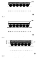
- Figure 1 shows an exemplary pre-product for a dry transformer high voltage coil in 1st stage of its production in a sketch 10.
- a layer 12 of conductor loops 14, 16, 18 is spirally wound around a winding axis 22 on a bobbin 22.
- Figure 2 shows an exemplary pre-product for a dry transformer high voltage coil in 2nd stage of its production in a sketch 30.
- an outer insulation layer 32 of soft consistency in this case strip-shaped polyester felt, has been wound around the layer of conductors. Since the material of the outer insulation layer 32 is soft, the outer shape of the layer of conductors is caved therein.
- Figure 3 shows an exemplary pre-product for a dry transformer high voltage coil in 3rd stage of its production in a sketch 40.
- the outer insulation layer 42 has been impregnated with a liquid resin also in the wedged areas inbetween the loops of conductors.
- Figure 4 shows an exemplary pre-product for a dry transformer high voltage coil in 4 th stage of its production in a sketch 50.
- an inner insulation layer 52 in this case a polyester foil, has been applied on the impregnated outer insulation layer.
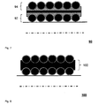
- Figure 5 shows an exemplary pre-product for a dry transformer high voltage coil in 5 th stage of its production in a sketch 60.
- An outer insulation 62 layer from polyester felt has been applied on the inner insulation layer.
- Figure 6 shows an exemplary pre-product for a dry transformer high voltage coil in 6 th stage of its production in a sketch 70.
- the outer insulation layer 72 from polyester felt has been impregnated with liquid resin.
- Figure 7 shows an exemplary pre-product for a dry transformer high voltage coil in final stage of its production in a sketch 80.
- a second layer 94 of conductors has been wound around the insulation layer and the first layer 92 of conductors below.
- a real coil might comprise significant more layers of electrical conductors and insulation layers inbetween.
- Figure 8 shows an exemplary dry transformer high voltage coil in a sketch 100. Due to a curing process the interim insulation layer with its inner and two outer insulation layers is now converted into a consistent solid final insulation layer 102.
Landscapes
- Engineering & Computer Science (AREA)
- Power Engineering (AREA)
- Insulating Of Coils (AREA)
Abstract
Description
- The invention is related to a pre-product for a dry transformer high voltage coil, comprising at least two radially adjacent layers of a wound electrical conductor with an interim laminar insulation layer inbetween, wherein the interim insulation layer is foreseen to be transformed to a final insulation layer by curing process.
- It is known that coils for dry transformers in high voltage applications, for example with a rated voltage in the range of 6kV to 36kV, comprise an electrical conductor, which is wound layer wise in radially adjacent layers around a winding axis. The axial winding direction typically changes inbetween radially adjacent winding layers so that a meander-like winding scheme is gained. Thus during operation of such a coil a voltage difference inbetween adjacent layers occurs, which is lowest, at this axial end of a layer, where the conductor is fed up to the radially above laying layer and which is highest at the axial opposite end of the respective layer.
- In order to avoid any electrical breakdown inbetween adjacent layers during operation of the coil, it is usual to provide an additional laminar insulation layer inbetween. This is for example made from a band-like wound prepreg material. Prepreg is a resin impregnated band material wherein the resin is in B-stage. So the resin respectively the band material is of harder consistency, wherein it has to become transferred to its final stage by a curing process at for example 150°C - 170°C. During this curing process the resin is melting back into a liquid state again and solidifies into a crystalline structure with extremely hard consistency. So an interim insulation layer is transformed to a final insulation layer by a curing process.
- In order to improve the insulation ability of such an additional insulation layer the number of voids respectively cavities, which are not filled with resin, has to be reduced as much as possible to avoid partial discharge.
- Disadvantageously within the state of the art is that a wound interim insulation layer typically comprises several voids especially in the wedge-shaped areas inbetween adjacent conductors within the same layer. Thus during the curing process there is not sufficient melted resin for filling the whole space inbetween the wound conductors and the quality of the final insulation layer is reduced therewith.
- It is objective of the invention to provide a pre-product for a dry transformer high voltage coil with interim laminar insulation layer inbetween adjacent layers of conductors, which affords the manufacturing of a dry transformer high voltage coil with improved insulation layer by a curing process.
- The problem is solved by a pre-product for a dry transformer high voltage coil of the aforementioned kind. This is characterized in that the interim insulation layer comprises an inner and two outer insulation layers, wherefrom the inner one is of hard consistency and the outer ones are of soft consistency.
- Basic idea of the invention is to reduce the amount of voids by providing outer insulation layers with a soft consistency. So the conductor loops which are wound on an outer layer with soft consistency are embedded therein, preferably with half of their diameter. Due to the embedding also the wedge shaped areas inbetween the conductors are filled with the material of soft consistency in an advantageous way. After curing the soft material it will be of hard consistency and suitable insulation material for the insulation layer of the coil.
- In order to ensure an electrically required minimum insulation thickness inbetween radially adjacent layers of conductors the interim laminar insulation layer comprises an inner insulation layer of hard consistency which is not considerably caveable so that its thickness is not reduced by the winding process whilst that a radial pressure is applied. An outer insulation layer of soft consistency is foreseen on both sides of the inner layer so that as well conductors which are under the interim insulation layer as conductors which are above the interim insulation layers are embedded therein.
- Thus the number of voids in the interim insulation layer of the pre-product for a coil is reduced in an advantageous way and the number of voids in the cured final insulation layer therewith. The insulation ability of such a layer is improved in an advantageous way.
- According to a further variant of the invention the consistency of the material of the inner insulation layer is as hard, that its thickness profile is not considerably caved while winding the adjacent layer of electrical conductors thereon during manufacturing process. An electrically required minimum insulation thickness inbetween adjacent layer of conductors is ensured therewith. Dependent on the electrical requirements it can be useful to adapt the thickness of the inner insulation layer along the axial length of the coil so that a wedge shaped cross section of the insulation layer is formed.
- According to a further variant of the invention that the consistency of the material of the outer insulation layers is as soft that its thickness profile is nearly form-locking caved while the adjacent layer of conductors are wound thereon during manufacturing process. The coil is manufactured from the radial inner layers of conductors respectively insulation to the radial outer layers. So a layer of conductors is embedded into an outer insulation layer and afterwards an outer insulation layer is applied on the layer of conductors. In the ideal case each loop of the layer of conductors is totally embedded in outer insulation layers so that no voids are present in the interim insulation layer.
- According to another embodiment of the invention the inner insulation layer comprises a foil. A foil has the advantage, that it has a constant thickness and is as hard, that the thickness is not significantly reduced when a pressure is applied thereon. A constant thickness even under pressure conditions affords a minimum insulation ability of the whole insulation layer. A suitable material for the foil is for example Kapton or PE wherein a suitable thickness is in the range of 100 µm to 3.5mm.
- According to a further embodiment of the invention the foil is covered with a coating that glues the single layers of the interim insulation layer together during the curing process. In contrast to resin a foil will not be molten during a curing process. Thus it has to be ensured, that a void-free adhesion of the foil with the both adjacent outer layers is gained. A suitable material for glue is for example resin-based, preferably resin in 'B' stage, what means, that it is in a flexible solid state wherein after remelting the resin in 'B' stage by a curing process a hardening process is initiated. Prepreg is a band-like material with resin in the 'B' stage.
- According to another embodiment of the invention the outer insulation layers have a varying thickness profile corresponding roughly to the outer shape of the layer of conductors to be embedded therein. The cross section of a typical electrical conductor is round so that a helical wedge-shaped area inbetween adjacent loops of conductors is built. Accordingly the shape of the not yet impressed outer insulation layer is thicker in the helical wedge-shaped area. In this case the deformation of the outer insulation layer is not as high if the layer of conductors is wound thereon.
- According to a further aspect of the invention the outer insulation layers comprise a resin impregnateable and/or resin impregnated material. In order to reduce the number of voids within the insulation material the resin is in the liquid state wherein the resin might become applied during the winding process of the transformer coil or shortly before.
- According to another embodiment of the invention the outer insulation layers comprise polyester felt. This is a material with a sufficient soft consistency which additionally has the ability to suck up liquid resin like a sponge. Thus the number of voids in the outer insulation layer is reduced in an advantageous way.
- According to another embodiment of the invention the resin impregnateable material respectively the polyester felt is of different color than the resin for impregnation. This facilitates an optical control of the quality of impregnation of the polyester felt. In case that the Polyester felt is of white color and the resin is of black color the impregnated and not impressed polyester felt would be of dark grey color. Any areas of poor impregnation would be white or light gray. Of course also other combinations of colors with a preferably high contrast are suitable.
- According to another embodiment of the invention the interim laminar insulation layer has been impregnated at least in part during applying it on the layer of electrical conductors thereunder. Thus it is ensured that potential voids in the edge are of inner and outer insulation layers for example are completely filled with liquid resin. In case that there is more resin than voids to be filled the dispensable resin is remaining on the surface of the coil for impregnating further layers which will be applied thereon.
- The problem is also solved by a method for manufacturing a dry transformer high voltage coil, comprising the step of applying heat on a pre-product for a dry transformer high voltage coil according to the invention. During such a curing process a temperature of for example 200°C is applied for 2 hours so that the resin can be completely hardened therewith. After the curing process the formally soft outer insulation layer and the inner layer are combined to a consistent insulation layer of hard consistency.
- The problem of the invention is additionally solved by a dry transformer high voltage coil which has been manufactured according to the aforementioned method of the invention. Thus the quality of the insulation layers is improved by reducing the number of voids therein.
- Further advantageous embodiments of the invention are mentioned in the dependent claims.
- The invention will now be further explained by means of an exemplary embodiment and with reference to the accompanying drawings, in which:
- Figure 1
- shows an exemplary pre-product for a dry transformer high voltage coil in 1 st stage,
- Figure 2
- shows an exemplary pre-product for a dry transformer high voltage coil in 2nd stage,
- Figure 3
- shows an exemplary pre-product for a dry transformer high voltage coil in 3rd stage,
- Figure 4
- shows an exemplary pre-product for a dry transformer high voltage coil in 4th stage,
- Figure 5
- shows an exemplary pre-product for a dry transformer high voltage coil in 5th stage,
- Figure 6
- shows an exemplary pre-product for a dry transformer high voltage coil in 6tht stage,
- Figure 7
- shows an exemplary pre-product for a dry transformer high voltage coil in final stage,
- Figure 8
- shows an exemplary dry transformer high voltage coil
-
Figure 1 shows an exemplary pre-product for a dry transformer high voltage coil in 1st stage of its production in asketch 10. Alayer 12 ofconductor loops axis 22 on abobbin 22. -
Figure 2 shows an exemplary pre-product for a dry transformer high voltage coil in 2nd stage of its production in asketch 30. Here anouter insulation layer 32 of soft consistency, in this case strip-shaped polyester felt, has been wound around the layer of conductors. Since the material of theouter insulation layer 32 is soft, the outer shape of the layer of conductors is caved therein. -
Figure 3 shows an exemplary pre-product for a dry transformer high voltage coil in 3rd stage of its production in asketch 40. Here theouter insulation layer 42 has been impregnated with a liquid resin also in the wedged areas inbetween the loops of conductors. -
Figure 4 shows an exemplary pre-product for a dry transformer high voltage coil in 4th stage of its production in asketch 50. Here aninner insulation layer 52, in this case a polyester foil, has been applied on the impregnated outer insulation layer. -
Figure 5 shows an exemplary pre-product for a dry transformer high voltage coil in 5th stage of its production in asketch 60. Anouter insulation 62 layer from polyester felt has been applied on the inner insulation layer. -
Figure 6 shows an exemplary pre-product for a dry transformer high voltage coil in 6th stage of its production in asketch 70. Theouter insulation layer 72 from polyester felt has been impregnated with liquid resin. -
Figure 7 shows an exemplary pre-product for a dry transformer high voltage coil in final stage of its production in a sketch 80. Here asecond layer 94 of conductors has been wound around the insulation layer and thefirst layer 92 of conductors below. Of course a real coil might comprise significant more layers of electrical conductors and insulation layers inbetween. -
Figure 8 shows an exemplary dry transformer high voltage coil in asketch 100. Due to a curing process the interim insulation layer with its inner and two outer insulation layers is now converted into a consistent solidfinal insulation layer 102. -
- 10
- exemplary pre-product for a dry transformer high voltage coil in 1 st stage
- 12
- fist layer of wound electrical conductors
- 14
- first conductor loop of first layer
- 16
- second conductor loop of first layer
- 18
- third conductor loop of first layer
- 20
- bobbin
- 22
- axis of rotation
- 30
- exemplary pre-product for a dry transformer high voltage coil in 2nd stage
- 32
- outer insulation layer
- 40
- exemplary pre-product for a dry transformer high voltage coil in 3rd stage
- 42
- outer insulation layer impregnated with resin
- 50
- exemplary pre-product for a dry transformer high voltage coil in 4th stage
- 52
- inner insulation layer
- 60
- exemplary pre-product for a dry transformer high voltage coil in 5th stage
- 62
- outer insulation layer
- 70
- exemplary pre-product for a dry transformer high voltage coil in 6th stage
- 72
- interim insulation layer
- 74
- outer insulation layer
- 76
- inner insulation layer
- 78
- outer insulation layer
- 90
- exemplary pre-product for a dry transformer high voltage coil in final stage
- 92
- fist layer of wound electrical conductors
- 94
- second layer of wound electrical conductors
- 100
- exemplary dry transformer high voltage coil
- 102
- final insulation layer
Claims (12)
- Pre-product (90) for a dry transformer high voltage coil (100), comprising at least two radially adjacent layers (12, 92, 94) of a wound electrical conductor (14, 16, 18) with an interim laminar insulation layer (72) inbetween, wherein the interim insulation layer (72) is foreseen to be transformed to a final insulation layer (102) by curing process,
characterized in that
the interim insulation layer (72) comprises an inner (76) and two outer (32, 42, 62, 80) insulation layers, wherefrom the inner one (76) is of hard consistency and the outer ones (32, 42, 62, 80) are of soft consistency. - Pre-product for a dry transformer high voltage coil according to claim 1, characterized in that the consistency of the material of the inner insulation layer (76) is as hard, that its thickness profile is not considerably caved while winding the adjacent layer (12, 92, 94) of electrical conductors (14, 16, 18) thereon during manufacturing process.
- Pre-product for a dry transformer high voltage coil according to claim 1 or 2, characterized in that the consistency of the material of the outer insulation layers (32, 42, 62, 80) is as soft that its thickness profile is nearly form-locking caved while winding the adjacent layer (12, 92, 94) of conductors (14, 16, 18) thereon during manufacturing process.
- Pre-product for a dry transformer high voltage coil according any of the previous claims, characterized in that the inner insulation layer (76) comprises a foil.
- Pre-product for a dry transformer high voltage coil according to claim 4, characterized in that the foil is covered with a coating that glues the interim insulation layer (72) together during the curing process.
- Pre-product for a dry transformer high voltage coil according to any of the previous claims, characterized in that the outer insulation layers (32, 42, 62, 80) have a varying thickness profile corresponding roughly to the outer shape of the layer (12, 92, 94) of conductors (14, 16, 18) to be embedded therein.
- Pre-product for a dry transformer high voltage coil according to any of the previous claims, characterized in that the outer insulation layers (32, 42, 62, 80) comprise a resin impregnateable and/or resin impregnated material.
- Pre-product for a dry transformer high voltage coil according to claim 7, characterized in that the outer insulation layers (32, 42, 62, 80) comprise polyester felt.
- Pre-product for a dry transformer high voltage coil according to any of the previous claims, characterized in that the resin impregnateable material respectively the polyester felt is of different color than the resin for impregnation.
- Pre-product for a dry transformer high voltage coil according to claim 7 to 9, characterized in that the interim laminar insulation layer (72) has been impregnated at least in part during applying it on the layer (12, 92, 94) of electrical conductors (14, 16, 18) thereunder.
- Method for manufacturing a dry transformer high voltage coil (100), comprising the step of applying heat on a pre-product for a dry transformer high voltage coil (90) according to claim 1 to 10.
- Dry transformer high voltage coil, characterized in that it has been manufactured according to the method of claim 11.
Priority Applications (1)
| Application Number | Priority Date | Filing Date | Title |
|---|---|---|---|
| EP14003469.5A EP3007190B1 (en) | 2014-10-09 | 2014-10-09 | Pre-product for a dry transformer high voltage coil |
Applications Claiming Priority (1)
| Application Number | Priority Date | Filing Date | Title |
|---|---|---|---|
| EP14003469.5A EP3007190B1 (en) | 2014-10-09 | 2014-10-09 | Pre-product for a dry transformer high voltage coil |
Publications (2)
| Publication Number | Publication Date |
|---|---|
| EP3007190A1 true EP3007190A1 (en) | 2016-04-13 |
| EP3007190B1 EP3007190B1 (en) | 2020-05-20 |
Family
ID=51690794
Family Applications (1)
| Application Number | Title | Priority Date | Filing Date |
|---|---|---|---|
| EP14003469.5A Active EP3007190B1 (en) | 2014-10-09 | 2014-10-09 | Pre-product for a dry transformer high voltage coil |
Country Status (1)
| Country | Link |
|---|---|
| EP (1) | EP3007190B1 (en) |
Cited By (1)
| Publication number | Priority date | Publication date | Assignee | Title |
|---|---|---|---|---|
| JP2022054076A (en) * | 2020-09-25 | 2022-04-06 | 株式会社スーリヤ | High voltage transformer |
Citations (5)
| Publication number | Priority date | Publication date | Assignee | Title |
|---|---|---|---|---|
| US3263196A (en) * | 1963-07-16 | 1966-07-26 | Mc Graw Edison Co | Encapsulated electrical coil having means to aid impregnation |
| EP0012542A1 (en) * | 1978-12-01 | 1980-06-25 | Westinghouse Electric Corporation | Method of making heat curable adhesive coated insulation for transformers |
| EP0150921A1 (en) * | 1984-01-09 | 1985-08-07 | Westinghouse Electric Corporation | Method of making a void-free non-cellulose electrical winding |
| EP0336053A2 (en) * | 1988-04-08 | 1989-10-11 | ANT Nachrichtentechnik GmbH | Method and devices for isolating high-voltage metallic parts |
| US20110291791A1 (en) * | 2010-05-26 | 2011-12-01 | Abb Technology Ag | Method for producing windings for a dry-type transformer |
-
2014
- 2014-10-09 EP EP14003469.5A patent/EP3007190B1/en active Active
Patent Citations (5)
| Publication number | Priority date | Publication date | Assignee | Title |
|---|---|---|---|---|
| US3263196A (en) * | 1963-07-16 | 1966-07-26 | Mc Graw Edison Co | Encapsulated electrical coil having means to aid impregnation |
| EP0012542A1 (en) * | 1978-12-01 | 1980-06-25 | Westinghouse Electric Corporation | Method of making heat curable adhesive coated insulation for transformers |
| EP0150921A1 (en) * | 1984-01-09 | 1985-08-07 | Westinghouse Electric Corporation | Method of making a void-free non-cellulose electrical winding |
| EP0336053A2 (en) * | 1988-04-08 | 1989-10-11 | ANT Nachrichtentechnik GmbH | Method and devices for isolating high-voltage metallic parts |
| US20110291791A1 (en) * | 2010-05-26 | 2011-12-01 | Abb Technology Ag | Method for producing windings for a dry-type transformer |
Cited By (1)
| Publication number | Priority date | Publication date | Assignee | Title |
|---|---|---|---|---|
| JP2022054076A (en) * | 2020-09-25 | 2022-04-06 | 株式会社スーリヤ | High voltage transformer |
Also Published As
| Publication number | Publication date |
|---|---|
| EP3007190B1 (en) | 2020-05-20 |
Similar Documents
| Publication | Publication Date | Title |
|---|---|---|
| US3303079A (en) | Method of manufacture of rocket chambers having an integral insulator or liner | |
| EP0368038B2 (en) | High voltage insulation system for electric machines | |
| EP3103124B1 (en) | Condenser core | |
| EP0150921B1 (en) | Method of making a void-free non-cellulose electrical winding | |
| US8316528B2 (en) | Method for making electrical windings for transformers and electrical apparatus | |
| US20100007226A1 (en) | Conductor bar for the stator of a generator, and method for its production | |
| CN1783369A (en) | Transformer | |
| EP2320440B1 (en) | Transformer winding and a method of reinforcing a transformer winding | |
| EP3007190B1 (en) | Pre-product for a dry transformer high voltage coil | |
| US20140083592A1 (en) | Method of producing an electrical insulation system for an electric machine | |
| US2246159A (en) | Electrical coil | |
| DE102007053685A1 (en) | Manufacturing method for a multi-layer transformer winding with insulation layer | |
| US20200321820A1 (en) | Stator and method of manufacturing stator | |
| DE102010001991B4 (en) | Flat conductor device with two braided insulating layers and manufacturing method | |
| RU2243095C2 (en) | Method of manufacturing sliding bearing | |
| JP6923578B2 (en) | Pressure vessel | |
| WO2016088541A1 (en) | Wire-wound resistor and method for manufacturing same | |
| JP2007282410A (en) | Stator coil of rotating electrical machine, method for manufacturing stator coil of rotating electrical machine, semiconductive sheet, semiconductive tape, and rotating electrical machine | |
| JPS58175946A (en) | Rotating electric machine windings made of insulated round wires | |
| JP2008182020A (en) | Molded coil | |
| JP6477448B2 (en) | Motor coil structure | |
| RU2566810C2 (en) | Method of coil manufacturing of high voltage electrotechnical device | |
| US20080286505A1 (en) | Mica-Reinforced Insulation | |
| EP3953953B1 (en) | Climate-proof magnetic coil | |
| EP2797211B1 (en) | Electrical machine and method for manufacturing an electrical machine |
Legal Events
| Date | Code | Title | Description |
|---|---|---|---|
| PUAI | Public reference made under article 153(3) epc to a published international application that has entered the european phase |
Free format text: ORIGINAL CODE: 0009012 |
|
| AK | Designated contracting states |
Kind code of ref document: A1 Designated state(s): AL AT BE BG CH CY CZ DE DK EE ES FI FR GB GR HR HU IE IS IT LI LT LU LV MC MK MT NL NO PL PT RO RS SE SI SK SM TR |
|
| AX | Request for extension of the european patent |
Extension state: BA ME |
|
| 17P | Request for examination filed |
Effective date: 20160923 |
|
| RAP1 | Party data changed (applicant data changed or rights of an application transferred) |
Owner name: ABB SCHWEIZ AG |
|
| STAA | Information on the status of an ep patent application or granted ep patent |
Free format text: STATUS: EXAMINATION IS IN PROGRESS |
|
| 17Q | First examination report despatched |
Effective date: 20170921 |
|
| GRAP | Despatch of communication of intention to grant a patent |
Free format text: ORIGINAL CODE: EPIDOSNIGR1 |
|
| STAA | Information on the status of an ep patent application or granted ep patent |
Free format text: STATUS: GRANT OF PATENT IS INTENDED |
|
| INTG | Intention to grant announced |
Effective date: 20191114 |
|
| RIN1 | Information on inventor provided before grant (corrected) |
Inventor name: TEPPER, JENS Inventor name: WEBER, BENJAMIN Inventor name: ZILLMANN, KARL-HEINZ Inventor name: SOETEBIER, SVEN |
|
| GRAJ | Information related to disapproval of communication of intention to grant by the applicant or resumption of examination proceedings by the epo deleted |
Free format text: ORIGINAL CODE: EPIDOSDIGR1 |
|
| STAA | Information on the status of an ep patent application or granted ep patent |
Free format text: STATUS: EXAMINATION IS IN PROGRESS |
|
| GRAP | Despatch of communication of intention to grant a patent |
Free format text: ORIGINAL CODE: EPIDOSNIGR1 |
|
| STAA | Information on the status of an ep patent application or granted ep patent |
Free format text: STATUS: GRANT OF PATENT IS INTENDED |
|
| RAP1 | Party data changed (applicant data changed or rights of an application transferred) |
Owner name: ABB POWER GRIDS SWITZERLAND AG |
|
| INTC | Intention to grant announced (deleted) | ||
| GRAS | Grant fee paid |
Free format text: ORIGINAL CODE: EPIDOSNIGR3 |
|
| INTG | Intention to grant announced |
Effective date: 20200317 |
|
| GRAA | (expected) grant |
Free format text: ORIGINAL CODE: 0009210 |
|
| STAA | Information on the status of an ep patent application or granted ep patent |
Free format text: STATUS: THE PATENT HAS BEEN GRANTED |
|
| AK | Designated contracting states |
Kind code of ref document: B1 Designated state(s): AL AT BE BG CH CY CZ DE DK EE ES FI FR GB GR HR HU IE IS IT LI LT LU LV MC MK MT NL NO PL PT RO RS SE SI SK SM TR |
|
| REG | Reference to a national code |
Ref country code: GB Ref legal event code: FG4D |
|
| REG | Reference to a national code |
Ref country code: CH Ref legal event code: EP |
|
| REG | Reference to a national code |
Ref country code: DE Ref legal event code: R096 Ref document number: 602014065636 Country of ref document: DE |
|
| REG | Reference to a national code |
Ref country code: AT Ref legal event code: REF Ref document number: 1273152 Country of ref document: AT Kind code of ref document: T Effective date: 20200615 |
|
| REG | Reference to a national code |
Ref country code: NO Ref legal event code: T2 Effective date: 20200520 |
|
| REG | Reference to a national code |
Ref country code: LT Ref legal event code: MG4D |
|
| REG | Reference to a national code |
Ref country code: NL Ref legal event code: MP Effective date: 20200520 |
|
| PG25 | Lapsed in a contracting state [announced via postgrant information from national office to epo] |
Ref country code: LT Free format text: LAPSE BECAUSE OF FAILURE TO SUBMIT A TRANSLATION OF THE DESCRIPTION OR TO PAY THE FEE WITHIN THE PRESCRIBED TIME-LIMIT Effective date: 20200520 Ref country code: SE Free format text: LAPSE BECAUSE OF FAILURE TO SUBMIT A TRANSLATION OF THE DESCRIPTION OR TO PAY THE FEE WITHIN THE PRESCRIBED TIME-LIMIT Effective date: 20200520 Ref country code: GR Free format text: LAPSE BECAUSE OF FAILURE TO SUBMIT A TRANSLATION OF THE DESCRIPTION OR TO PAY THE FEE WITHIN THE PRESCRIBED TIME-LIMIT Effective date: 20200821 Ref country code: IS Free format text: LAPSE BECAUSE OF FAILURE TO SUBMIT A TRANSLATION OF THE DESCRIPTION OR TO PAY THE FEE WITHIN THE PRESCRIBED TIME-LIMIT Effective date: 20200920 Ref country code: FI Free format text: LAPSE BECAUSE OF FAILURE TO SUBMIT A TRANSLATION OF THE DESCRIPTION OR TO PAY THE FEE WITHIN THE PRESCRIBED TIME-LIMIT Effective date: 20200520 Ref country code: PT Free format text: LAPSE BECAUSE OF FAILURE TO SUBMIT A TRANSLATION OF THE DESCRIPTION OR TO PAY THE FEE WITHIN THE PRESCRIBED TIME-LIMIT Effective date: 20200921 |
|
| PG25 | Lapsed in a contracting state [announced via postgrant information from national office to epo] |
Ref country code: RS Free format text: LAPSE BECAUSE OF FAILURE TO SUBMIT A TRANSLATION OF THE DESCRIPTION OR TO PAY THE FEE WITHIN THE PRESCRIBED TIME-LIMIT Effective date: 20200520 Ref country code: LV Free format text: LAPSE BECAUSE OF FAILURE TO SUBMIT A TRANSLATION OF THE DESCRIPTION OR TO PAY THE FEE WITHIN THE PRESCRIBED TIME-LIMIT Effective date: 20200520 Ref country code: HR Free format text: LAPSE BECAUSE OF FAILURE TO SUBMIT A TRANSLATION OF THE DESCRIPTION OR TO PAY THE FEE WITHIN THE PRESCRIBED TIME-LIMIT Effective date: 20200520 Ref country code: BG Free format text: LAPSE BECAUSE OF FAILURE TO SUBMIT A TRANSLATION OF THE DESCRIPTION OR TO PAY THE FEE WITHIN THE PRESCRIBED TIME-LIMIT Effective date: 20200820 |
|
| REG | Reference to a national code |
Ref country code: AT Ref legal event code: MK05 Ref document number: 1273152 Country of ref document: AT Kind code of ref document: T Effective date: 20200520 |
|
| PG25 | Lapsed in a contracting state [announced via postgrant information from national office to epo] |
Ref country code: AL Free format text: LAPSE BECAUSE OF FAILURE TO SUBMIT A TRANSLATION OF THE DESCRIPTION OR TO PAY THE FEE WITHIN THE PRESCRIBED TIME-LIMIT Effective date: 20200520 Ref country code: NL Free format text: LAPSE BECAUSE OF FAILURE TO SUBMIT A TRANSLATION OF THE DESCRIPTION OR TO PAY THE FEE WITHIN THE PRESCRIBED TIME-LIMIT Effective date: 20200520 |
|
| PG25 | Lapsed in a contracting state [announced via postgrant information from national office to epo] |
Ref country code: RO Free format text: LAPSE BECAUSE OF FAILURE TO SUBMIT A TRANSLATION OF THE DESCRIPTION OR TO PAY THE FEE WITHIN THE PRESCRIBED TIME-LIMIT Effective date: 20200520 Ref country code: CZ Free format text: LAPSE BECAUSE OF FAILURE TO SUBMIT A TRANSLATION OF THE DESCRIPTION OR TO PAY THE FEE WITHIN THE PRESCRIBED TIME-LIMIT Effective date: 20200520 Ref country code: ES Free format text: LAPSE BECAUSE OF FAILURE TO SUBMIT A TRANSLATION OF THE DESCRIPTION OR TO PAY THE FEE WITHIN THE PRESCRIBED TIME-LIMIT Effective date: 20200520 Ref country code: DK Free format text: LAPSE BECAUSE OF FAILURE TO SUBMIT A TRANSLATION OF THE DESCRIPTION OR TO PAY THE FEE WITHIN THE PRESCRIBED TIME-LIMIT Effective date: 20200520 Ref country code: AT Free format text: LAPSE BECAUSE OF FAILURE TO SUBMIT A TRANSLATION OF THE DESCRIPTION OR TO PAY THE FEE WITHIN THE PRESCRIBED TIME-LIMIT Effective date: 20200520 Ref country code: SM Free format text: LAPSE BECAUSE OF FAILURE TO SUBMIT A TRANSLATION OF THE DESCRIPTION OR TO PAY THE FEE WITHIN THE PRESCRIBED TIME-LIMIT Effective date: 20200520 Ref country code: EE Free format text: LAPSE BECAUSE OF FAILURE TO SUBMIT A TRANSLATION OF THE DESCRIPTION OR TO PAY THE FEE WITHIN THE PRESCRIBED TIME-LIMIT Effective date: 20200520 |
|
| REG | Reference to a national code |
Ref country code: DE Ref legal event code: R097 Ref document number: 602014065636 Country of ref document: DE |
|
| PG25 | Lapsed in a contracting state [announced via postgrant information from national office to epo] |
Ref country code: PL Free format text: LAPSE BECAUSE OF FAILURE TO SUBMIT A TRANSLATION OF THE DESCRIPTION OR TO PAY THE FEE WITHIN THE PRESCRIBED TIME-LIMIT Effective date: 20200520 Ref country code: SK Free format text: LAPSE BECAUSE OF FAILURE TO SUBMIT A TRANSLATION OF THE DESCRIPTION OR TO PAY THE FEE WITHIN THE PRESCRIBED TIME-LIMIT Effective date: 20200520 |
|
| PLBE | No opposition filed within time limit |
Free format text: ORIGINAL CODE: 0009261 |
|
| STAA | Information on the status of an ep patent application or granted ep patent |
Free format text: STATUS: NO OPPOSITION FILED WITHIN TIME LIMIT |
|
| REG | Reference to a national code |
Ref country code: NO Ref legal event code: CHAD Owner name: ABB POWER GRIDS SWITZERLAND AG, CH |
|
| 26N | No opposition filed |
Effective date: 20210223 |
|
| PG25 | Lapsed in a contracting state [announced via postgrant information from national office to epo] |
Ref country code: SI Free format text: LAPSE BECAUSE OF FAILURE TO SUBMIT A TRANSLATION OF THE DESCRIPTION OR TO PAY THE FEE WITHIN THE PRESCRIBED TIME-LIMIT Effective date: 20200520 |
|
| GBPC | Gb: european patent ceased through non-payment of renewal fee |
Effective date: 20201009 |
|
| PG25 | Lapsed in a contracting state [announced via postgrant information from national office to epo] |
Ref country code: MC Free format text: LAPSE BECAUSE OF FAILURE TO SUBMIT A TRANSLATION OF THE DESCRIPTION OR TO PAY THE FEE WITHIN THE PRESCRIBED TIME-LIMIT Effective date: 20200520 Ref country code: LU Free format text: LAPSE BECAUSE OF NON-PAYMENT OF DUE FEES Effective date: 20201009 |
|
| REG | Reference to a national code |
Ref country code: BE Ref legal event code: MM Effective date: 20201031 |
|
| PG25 | Lapsed in a contracting state [announced via postgrant information from national office to epo] |
Ref country code: BE Free format text: LAPSE BECAUSE OF NON-PAYMENT OF DUE FEES Effective date: 20201031 Ref country code: GB Free format text: LAPSE BECAUSE OF NON-PAYMENT OF DUE FEES Effective date: 20201009 |
|
| PG25 | Lapsed in a contracting state [announced via postgrant information from national office to epo] |
Ref country code: IE Free format text: LAPSE BECAUSE OF NON-PAYMENT OF DUE FEES Effective date: 20201009 |
|
| REG | Reference to a national code |
Ref country code: NO Ref legal event code: CHAD Owner name: HITACHI ENERGY SWITZERLAND AG, CH |
|
| PG25 | Lapsed in a contracting state [announced via postgrant information from national office to epo] |
Ref country code: TR Free format text: LAPSE BECAUSE OF FAILURE TO SUBMIT A TRANSLATION OF THE DESCRIPTION OR TO PAY THE FEE WITHIN THE PRESCRIBED TIME-LIMIT Effective date: 20200520 Ref country code: MT Free format text: LAPSE BECAUSE OF FAILURE TO SUBMIT A TRANSLATION OF THE DESCRIPTION OR TO PAY THE FEE WITHIN THE PRESCRIBED TIME-LIMIT Effective date: 20200520 Ref country code: CY Free format text: LAPSE BECAUSE OF FAILURE TO SUBMIT A TRANSLATION OF THE DESCRIPTION OR TO PAY THE FEE WITHIN THE PRESCRIBED TIME-LIMIT Effective date: 20200520 |
|
| REG | Reference to a national code |
Ref country code: DE Ref legal event code: R081 Ref document number: 602014065636 Country of ref document: DE Owner name: HITACHI ENERGY SWITZERLAND AG, CH Free format text: FORMER OWNER: ABB POWER GRIDS SWITZERLAND AG, BADEN, CH Ref country code: DE Ref legal event code: R081 Ref document number: 602014065636 Country of ref document: DE Owner name: HITACHI ENERGY LTD, CH Free format text: FORMER OWNER: ABB POWER GRIDS SWITZERLAND AG, BADEN, CH |
|
| PG25 | Lapsed in a contracting state [announced via postgrant information from national office to epo] |
Ref country code: MK Free format text: LAPSE BECAUSE OF FAILURE TO SUBMIT A TRANSLATION OF THE DESCRIPTION OR TO PAY THE FEE WITHIN THE PRESCRIBED TIME-LIMIT Effective date: 20200520 |
|
| P01 | Opt-out of the competence of the unified patent court (upc) registered |
Effective date: 20230527 |
|
| REG | Reference to a national code |
Ref country code: NO Ref legal event code: CHAD Owner name: HITACHI ENERGY LTD, CH |
|
| REG | Reference to a national code |
Ref country code: DE Ref legal event code: R082 Ref document number: 602014065636 Country of ref document: DE Representative=s name: DENNEMEYER & ASSOCIATES RECHTSANWALTSGESELLSCH, DE Ref country code: DE Ref legal event code: R082 Ref document number: 602014065636 Country of ref document: DE Representative=s name: DENNEMEYER & ASSOCIATES S.A., DE Ref country code: DE Ref legal event code: R081 Ref document number: 602014065636 Country of ref document: DE Owner name: HITACHI ENERGY LTD, CH Free format text: FORMER OWNER: HITACHI ENERGY SWITZERLAND AG, BADEN, CH |
|
| REG | Reference to a national code |
Ref country code: DE Ref legal event code: R082 Ref document number: 602014065636 Country of ref document: DE Representative=s name: DENNEMEYER & ASSOCIATES RECHTSANWALTSGESELLSCH, DE |
|
| REG | Reference to a national code |
Ref country code: CH Ref legal event code: U11 Free format text: ST27 STATUS EVENT CODE: U-0-0-U10-U11 (AS PROVIDED BY THE NATIONAL OFFICE) Effective date: 20251101 |
|
| PGFP | Annual fee paid to national office [announced via postgrant information from national office to epo] |
Ref country code: DE Payment date: 20251021 Year of fee payment: 12 |
|
| PGFP | Annual fee paid to national office [announced via postgrant information from national office to epo] |
Ref country code: NO Payment date: 20251024 Year of fee payment: 12 |
|
| PGFP | Annual fee paid to national office [announced via postgrant information from national office to epo] |
Ref country code: IT Payment date: 20251024 Year of fee payment: 12 |
|
| PGFP | Annual fee paid to national office [announced via postgrant information from national office to epo] |
Ref country code: FR Payment date: 20251030 Year of fee payment: 12 |
|
| PGFP | Annual fee paid to national office [announced via postgrant information from national office to epo] |
Ref country code: CH Payment date: 20251101 Year of fee payment: 12 |