EP3007026A2 - System and method for controlling flow rate ratio - Google Patents
System and method for controlling flow rate ratio Download PDFInfo
- Publication number
- EP3007026A2 EP3007026A2 EP15187115.9A EP15187115A EP3007026A2 EP 3007026 A2 EP3007026 A2 EP 3007026A2 EP 15187115 A EP15187115 A EP 15187115A EP 3007026 A2 EP3007026 A2 EP 3007026A2
- Authority
- EP
- European Patent Office
- Prior art keywords
- flow rate
- stream
- differential pressure
- rate ratio
- branch stream
- Prior art date
- Legal status (The legal status is an assumption and is not a legal conclusion. Google has not performed a legal analysis and makes no representation as to the accuracy of the status listed.)
- Granted
Links
Images




Classifications
-
- H—ELECTRICITY
- H01—ELECTRIC ELEMENTS
- H01M—PROCESSES OR MEANS, e.g. BATTERIES, FOR THE DIRECT CONVERSION OF CHEMICAL ENERGY INTO ELECTRICAL ENERGY
- H01M8/00—Fuel cells; Manufacture thereof
- H01M8/04—Auxiliary arrangements, e.g. for control of pressure or for circulation of fluids
- H01M8/04298—Processes for controlling fuel cells or fuel cell systems
- H01M8/04694—Processes for controlling fuel cells or fuel cell systems characterised by variables to be controlled
- H01M8/04746—Pressure; Flow
- H01M8/04753—Pressure; Flow of fuel cell reactants
-
- G—PHYSICS
- G05—CONTROLLING; REGULATING
- G05D—SYSTEMS FOR CONTROLLING OR REGULATING NON-ELECTRIC VARIABLES
- G05D11/00—Control of flow ratio
- G05D11/02—Controlling ratio of two or more flows of fluid or fluent material
- G05D11/13—Controlling ratio of two or more flows of fluid or fluent material characterised by the use of electric means
-
- G—PHYSICS
- G05—CONTROLLING; REGULATING
- G05D—SYSTEMS FOR CONTROLLING OR REGULATING NON-ELECTRIC VARIABLES
- G05D7/00—Control of flow
- G05D7/06—Control of flow characterised by the use of electric means
-
- G—PHYSICS
- G05—CONTROLLING; REGULATING
- G05D—SYSTEMS FOR CONTROLLING OR REGULATING NON-ELECTRIC VARIABLES
- G05D7/00—Control of flow
- G05D7/06—Control of flow characterised by the use of electric means
- G05D7/0617—Control of flow characterised by the use of electric means specially adapted for fluid materials
- G05D7/0629—Control of flow characterised by the use of electric means specially adapted for fluid materials characterised by the type of regulator means
- G05D7/0635—Control of flow characterised by the use of electric means specially adapted for fluid materials characterised by the type of regulator means by action on throttling means
-
- G—PHYSICS
- G05—CONTROLLING; REGULATING
- G05D—SYSTEMS FOR CONTROLLING OR REGULATING NON-ELECTRIC VARIABLES
- G05D7/00—Control of flow
- G05D7/06—Control of flow characterised by the use of electric means
- G05D7/0617—Control of flow characterised by the use of electric means specially adapted for fluid materials
- G05D7/0629—Control of flow characterised by the use of electric means specially adapted for fluid materials characterised by the type of regulator means
- G05D7/0635—Control of flow characterised by the use of electric means specially adapted for fluid materials characterised by the type of regulator means by action on throttling means
- G05D7/0641—Control of flow characterised by the use of electric means specially adapted for fluid materials characterised by the type of regulator means by action on throttling means using a plurality of throttling means
- G05D7/0664—Control of flow characterised by the use of electric means specially adapted for fluid materials characterised by the type of regulator means by action on throttling means using a plurality of throttling means the plurality of throttling means being arranged for the control of a plurality of diverging flows from a single flow
-
- H—ELECTRICITY
- H01—ELECTRIC ELEMENTS
- H01M—PROCESSES OR MEANS, e.g. BATTERIES, FOR THE DIRECT CONVERSION OF CHEMICAL ENERGY INTO ELECTRICAL ENERGY
- H01M8/00—Fuel cells; Manufacture thereof
- H01M8/04—Auxiliary arrangements, e.g. for control of pressure or for circulation of fluids
- H01M8/04082—Arrangements for control of reactant parameters, e.g. pressure or concentration
- H01M8/04089—Arrangements for control of reactant parameters, e.g. pressure or concentration of gaseous reactants
- H01M8/04097—Arrangements for control of reactant parameters, e.g. pressure or concentration of gaseous reactants with recycling of the reactants
-
- H—ELECTRICITY
- H01—ELECTRIC ELEMENTS
- H01M—PROCESSES OR MEANS, e.g. BATTERIES, FOR THE DIRECT CONVERSION OF CHEMICAL ENERGY INTO ELECTRICAL ENERGY
- H01M8/00—Fuel cells; Manufacture thereof
- H01M8/04—Auxiliary arrangements, e.g. for control of pressure or for circulation of fluids
- H01M8/04298—Processes for controlling fuel cells or fuel cell systems
- H01M8/04694—Processes for controlling fuel cells or fuel cell systems characterised by variables to be controlled
- H01M8/04746—Pressure; Flow
- H01M8/04761—Pressure; Flow of fuel cell exhausts
-
- H—ELECTRICITY
- H01—ELECTRIC ELEMENTS
- H01M—PROCESSES OR MEANS, e.g. BATTERIES, FOR THE DIRECT CONVERSION OF CHEMICAL ENERGY INTO ELECTRICAL ENERGY
- H01M8/00—Fuel cells; Manufacture thereof
- H01M8/06—Combination of fuel cells with means for production of reactants or for treatment of residues
- H01M8/0606—Combination of fuel cells with means for production of reactants or for treatment of residues with means for production of gaseous reactants
- H01M8/0612—Combination of fuel cells with means for production of reactants or for treatment of residues with means for production of gaseous reactants from carbon-containing material
- H01M8/0618—Reforming processes, e.g. autothermal, partial oxidation or steam reforming
-
- H—ELECTRICITY
- H01—ELECTRIC ELEMENTS
- H01M—PROCESSES OR MEANS, e.g. BATTERIES, FOR THE DIRECT CONVERSION OF CHEMICAL ENERGY INTO ELECTRICAL ENERGY
- H01M2250/00—Fuel cells for particular applications; Specific features of fuel cell system
- H01M2250/20—Fuel cells in motive systems, e.g. vehicle, ship, plane
-
- Y—GENERAL TAGGING OF NEW TECHNOLOGICAL DEVELOPMENTS; GENERAL TAGGING OF CROSS-SECTIONAL TECHNOLOGIES SPANNING OVER SEVERAL SECTIONS OF THE IPC; TECHNICAL SUBJECTS COVERED BY FORMER USPC CROSS-REFERENCE ART COLLECTIONS [XRACs] AND DIGESTS
- Y02—TECHNOLOGIES OR APPLICATIONS FOR MITIGATION OR ADAPTATION AGAINST CLIMATE CHANGE
- Y02E—REDUCTION OF GREENHOUSE GAS [GHG] EMISSIONS, RELATED TO ENERGY GENERATION, TRANSMISSION OR DISTRIBUTION
- Y02E60/00—Enabling technologies; Technologies with a potential or indirect contribution to GHG emissions mitigation
- Y02E60/30—Hydrogen technology
- Y02E60/50—Fuel cells
-
- Y—GENERAL TAGGING OF NEW TECHNOLOGICAL DEVELOPMENTS; GENERAL TAGGING OF CROSS-SECTIONAL TECHNOLOGIES SPANNING OVER SEVERAL SECTIONS OF THE IPC; TECHNICAL SUBJECTS COVERED BY FORMER USPC CROSS-REFERENCE ART COLLECTIONS [XRACs] AND DIGESTS
- Y02—TECHNOLOGIES OR APPLICATIONS FOR MITIGATION OR ADAPTATION AGAINST CLIMATE CHANGE
- Y02T—CLIMATE CHANGE MITIGATION TECHNOLOGIES RELATED TO TRANSPORTATION
- Y02T90/00—Enabling technologies or technologies with a potential or indirect contribution to GHG emissions mitigation
- Y02T90/40—Application of hydrogen technology to transportation, e.g. using fuel cells
Definitions
- This disclosure relates generally to high temperature application, and more particularly to a system and a method for controlling a flow rate ratio in a high temperature environment.
- a traditional way of controlling a recycle flow rate in the high temperature hybrid fuel cell system is generally by adjusting a gas driving device of the system, such as a blower or a compressor.
- a gas driving device of the system such as a blower or a compressor.
- it is slow due to the redistribution of pressure in a recycle loop of the high temperature hybrid fuel cell system.
- the fluctuation of differential pressure at an anode inlet of a fuel cell may affect durability and even its lifetime of the fuel cell, and the recycle flow rate may affect fuel utilization of the fuel cell and even the system efficiency.
- the differential pressure at the anode inlet of the fuel cell and the recycle flow rate cannot be controlled separately, due to lack of real time measurement and control of recycle flow rate ratio.
- a system for controlling a flow rate ratio comprises: an upstream device for generating a main stream, wherein the main stream is split into a first branch stream and a second branch stream at a splitting position; a first downstream device to which the first branch stream is diverted, wherein both the upstream device and the first downstream device operate at a high temperature which is larger than 300°C; a second downstream device to which the second branch stream is diverted; a measuring device for measuring differential pressures of two of the main stream, the first branch stream and the second branch stream; and a controlling device for controlling a flow rate ratio of the first branch stream to the main stream in real time in response to the measured differential pressures.
- a method for controlling a flow rate ratio using the above system comprises: a1) measuring real time differential pressures of two of the main stream, the first branch stream and the second branch stream; a2) calculating a flow rate ratio of the first branch stream to the main stream in real time with the measured differential pressures; a3) comparing the calculated flow rate ratio to a user-defined target flow rate ratio; and a4) controlling a flow rate of at least one of the first branch stream and the second branch stream in real time with the compared result.
- a system for controlling a recycle flow rate ratio comprises: a fuel cell comprising an anode for generating a tail gas, the anode comprising an inlet and an outlet; a fuel reformer for mixing a fuel with the tail gas from the outlet of the fuel cell to generate a reformed stream, wherein the reformed stream is split into a first branch stream and a second branch stream at a splitting position, and the first branch stream is returned to the inlet of the anode of the fuel cell for power generation; a cooler for removing heat from the second branch stream; a bottoming cycle including an external or internal combustion engine driven in response to the cooled second branch stream; a measuring device for measuring differential pressures of two of the main stream, the first branch stream and the second branch stream; and a controlling device for controlling a flow rate ratio of the first branch stream to the main stream in real time in response to the measured differential pressures.
- FIG. 1 illustrates a schematic block diagram of an embodiment of a high temperature system.
- the high temperature system 1 includes an upstream device 11, a first downstream device 12 and a second downstream device 13. Both the upstream device 11 and the first downstream device 12 operate at a high temperature which is larger than 300°C.
- the upstream device 11 generates a main stream S which is split into a first branch stream S1 and a second branch stream S2 at a splitting position Q.
- the main stream S has complex fluid or gas properties, for example, the main stream S can be fluid or gas having multi-components.
- the first branch stream S1 is diverted to the first downstream device 12 and is correspondingly processed in the first downstream device 12.
- the second branch stream S2 is diverted to the second downstream device 13 and is correspondingly processed in the second downstream device 13.
- a system for controlling a flow rate ratio further includes a measuring device and a controlling device (both of which are not shown in FIG. 1 ).
- the measuring device measures real time differential pressures DP 1 , DP 2 of two of the main stream S, the first branch stream S1 and the second branch stream S2.
- the controlling device controls the flow rate ratio RR of the first branch stream S 1 to the main stream S in real time in response to the measured differential pressures DP 1 , DP 2 .
- FIG. 7 illustrates a flowchart of a method for controlling a flow rate ratio using the above system in accordance with an embodiment of the present invention.
- a method for controlling a flow rate ratio using the above system in accordance with an embodiment of the present invention comprises the steps as following:
- the method for controlling the flow rate ratio further comprises the step as following:
- the high temperature system 1 can be a high temperature recycle system.
- FIG. 2 illustrates a schematic block diagram of an embodiment of a high temperature recycle system.
- the high temperature recycle system 2 similar to the high temperature system 1 of FIG. 1 , the high temperature recycle system 2 according to the embodiment includes an upstream device 11, a first downstream device 12 and a second downstream device 13. Both the upstream device 11 and the first downstream device 12 operate at a high temperature which is larger than 300°C.
- the upstream device 11 generates a main stream S which is split into a first branch stream S1 and a second branch stream S2 at a splitting position Q.
- the main stream S has complex fluid or gas properties, for example, the main stream S can be fluid or gas having multi-components.
- the first branch stream S1 is diverted to the first downstream device 12 and is correspondingly processed in the first downstream device 12.
- the second branch stream S2 is diverted to the second downstream device 13 and is correspondingly processed in the second downstream device 13.
- the high temperature recycle system 2 of FIG. 2 different from the high temperature system 1 of FIG. 1 , in the high temperature recycle system 2 of FIG. 2 , at least part of the first branch stream S1 is returned to the upstream device 11 for processing after the first branch stream S1 is passed through the first downstream device 12, and a flow rate ratio RR of the first branch stream S 1 to the main stream S is a recycle flow rate ratio RR of the first branch stream S1 to the main stream S.
- a system for controlling a flow rate ratio further includes a measuring device and a controlling device (both of which are not shown in FIG. 2 ).
- the measuring device measures real time differential pressures DP 1 , DP 2 of two of the main stream S, the first branch stream S1 and the second branch stream S2.
- the controlling device controls the recycle flow rate ratio RR in real time in response to the measured differential pressures DP 1 , DP 2 .
- a high temperature fuel cell system will be hereinafter taken as an example of a high temperature system for purpose to describe a system and a method for controlling a flow rate ratio in detail.
- FIG. 3 illustrates a schematic block diagram of a high temperature fuel cell system of an embodiment.
- the high temperature fuel cell system 3 includes a fuel reformer 31, a fuel cell 32, a cooler 331 and a bottoming cycle including an external or internal combustion engine 332.
- the fuel cell 32 which is for example a solid oxide fuel cell (SOFC) includes an anode 321 for electrochemically oxidizing fuel and a cathode 322 for electrochemically reducing oxygen.
- the anode 321 includes an inlet 3211 and an outlet 3212.
- a splitting position Q is located in an outlet of the fuel reformer 31.
- the fuel reformer 31 mixes a fuel with a tail gas generated from the outlet 3212 of the anode 321 of the fuel cell 32 and the fuel and the tail gas are reformed in the fuel reformer 32 to generate a reformed stream S as the main stream.
- the fuel can be for example biogas, natural gas, liquefied petroleum gas, methane, ethane, propane, methanol, ethanol, syngas, and other hydrocarbon fuels.
- the hydrocarbon fuel is reformed into hydrogen (H 2 ) and carbon monoxide (CO) by reforming reaction and at the same time, carbon monoxide and steam (H 2 O) is also transformed into carbon dioxide (CO 2 ) and hydrogen by transformation reaction.
- the reformed stream S includes multi-components, for example, the reformed stream S has mixed gas composition of hydrogen, carbon monoxide, carbon dioxide, methane (CH 4 ), steam and etc.
- the reformed stream S is split into a first branch stream S1 and a second branch stream S2 at the splitting position Q.
- the first branch stream S1 is diverted to the inlet 3211 of the anode 321 of the fuel cell 32 for high efficient power generation.
- the fuel cell 32 converts hydrogen and oxygen into water to produce electricity and heat.
- the byproduct water may exit from the outlet 3212 of the fuel cell 32 as steam in high temperature operations.
- the second branch stream S2 is diverted to the cooler 331.
- the cooler 331 removes heat from the second branch stream S2, and the external or internal combustion engine 332 is driven to generate additional electricity for providing increased efficiency of power generation in response to the cooled second branch stream, and the redundant portion is discharged as an exhaust from the external or internal combustion engine 332.
- the steam reforming reaction of hydrocarbons in the fuel reformer 31 is typically endothermic, and therefore, the reforming may utilize the heat generated by the typically exothermic electrochemical reactions of the fuel cell 32.
- the fuel reformer 31 acts as the upstream device, while the fuel cell 32 acts as the first downstream device, and the cooler 331 and the bottoming cycle including the external or internal combustion engine 332 together act as the second downstream device 33.
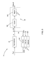
- FIG. 4 illustrates a schematic block diagram of a system for controlling a flow rate ratio based on FIG. 3 in accordance with a first embodiment of the present invention.
- a system 3a for controlling a flow rate ratio according to a first embodiment of the present invention further includes a measuring device 34 and a controlling device 35.
- the measuring device 34 measures differential pressures of two of the main stream S, the first branch stream S1 and the second branch stream S2.
- the controlling device 35 controls a flow rate ratio of the first branch stream S 1 to the main stream S in real time in response to the measured differential pressures.
- the measuring device 34 includes first and second differential pressure gauges 341, 342 which are the same and are both placed close to the splitting position Q.
- the first and second differential pressure gauges 341, 342 may be orifices.
- the first and second differential pressure gauges 341, 342 may be also venturi meters.
- the first differential pressure gauge 341 is located between the fuel reformer 31 as the upstream device and the splitting position Q for measuring a differential pressure DP 1 of the main stream S
- the second differential pressure gauge 342 is located between the fuel cell 32 as the first downstream device and the splitting position Q for measuring a differential pressure DP 2 of the first branch stream S 1.
- the system 3a for controlling the flow rate ratio further includes a flow rate ratio calculator 36.
- a calibrated coefficient K for the measuring device 34 that is, a calibrated coefficient K for the second differential pressure gauge 342 relative to the first differential pressure gauge 341 is pre-stored in the flow rate ratio calculator 36.
- the flow rate ratio calculator 36 calculates the flow rate ratio based on the measured differential pressures and the calibrated coefficient.
- FIG. 8 illustrates a schematic diagram used in determining the calibrated coefficient K for the measuring device 34.
- a variable gas source 81 is firstly prepared.
- the variable gas source 81 is connected to a mass flow rate controller 82, and the mass flow rate controller 82 is then connected with the first and the second differential pressure gauges 341, 342 of the measuring device 34.
- Gas flow rate of the mass flow rate controller 82 is changed and then, first and second differential pressure values DP c1 , DP c2 of the first and the second differential pressure gauges 341, 342 are recorded respectively.
- F represents the gas flow rate of the mass flow rate controller 82
- F1 and F2 respectively represent gas flow rate of the first and the second pressure gauges 341 and 34
- K 1 and K 2 respectively represent first and second coefficients of the first and the second differential pressure gauges 341 and 342
- ⁇ c represents a gas density of the variable gas source 81.
- ⁇ 1 represents a density of the first branch stream S1 and ⁇ represents a density of the main stream S.
- the controlling device 35 includes a controller 351 and an adjustable valve 352 for adjusting a flow rate.
- the controller 351 receives the flow rate ratio RR calculated from the flow rate ratio calculator 36, compares the calculated flow rate ratio RR to a user-defined target flow rate ratio and controls an opening position of the adjustable valve 352 based on the compared result.
- the controller 351 sends out a control signal to the adjustable valve 352 based on an error between the target flow rate ratio and the calculated flow rate ratio RR, and the adjustable valve 352 receives the control signal from the controller 351 and adjusts its opening position to control a flow rate of at least one of the first branch stream S1 and the second branch stream S2.
- the adjustable valve 352 is arranged between the splitting position Q and the second downstream device 33 for adjusting a flow rate of the second branch stream S2.
- the adjustable valve 352 is not limited to such an arrangement, for example, in another embodiment, the adjustable valve 352 may be also a three-way valve which is arranged at the splitting position Q for adjusting flow rates of the first and the second branch streams S1, S2.
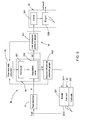
- FIG. 5 illustrates a schematic block diagram of a system for controlling a flow rate ratio based on FIG. 3 in accordance with a second embodiment of the present invention.
- a system 3b for controlling a flow rate ratio according to a second embodiment of the present invention further includes a measuring device 34 and a controlling device 35.
- the measuring device 34 measures differential pressures of two of the main stream S, the first branch stream S1 and the second branch stream S2.
- the controlling device 35 controls a flow rate ratio of the first branch stream S1 to the main stream S in real time in response to the measured differential pressures.
- the measuring device 34 includes first and second differential pressure gauges 341, 342 which are the same and are both placed close to the splitting position Q.
- the first and second differential pressure gauges 341, 342 may be orifices.
- the first and second differential pressure gauges 341, 342 may be also venturi meters.
- the first differential pressure gauge 341 is located between the splitting position Q and the second downstream device 33 for measuring a differential pressure DP 1 of the second branch stream S2
- the second differential pressure gauge 342 is located between the fuel cell 32 as the first downstream device and the splitting position Q for measuring a differential pressure DP 2 of the first branch stream S 1.
- the system 3b for controlling the flow rate ratio further includes a flow rate ratio calculator 36.
- a calibrated coefficient K for the measuring device 34 (that is, a calibrated coefficient K for the second differential pressure gauge 342 relative to the first differential pressure gauge 341, as shown in equation (4)) is pre-stored in the flow rate ratio calculator 36.
- the calibrated coefficient K for the measuring device 34 can be determined by using the above method with reference to FIG. 8 .
- the flow rate ratio calculator 36 calculates the flow rate ratio RR based on the measured differential pressures DP 1 , DP 2 and the calibrated coefficient K.
- ⁇ 2 represents a density of the first branch stream S1 and ⁇ 1 represents a density of the second branch stream S2.
- the controlling device 35 includes a controller 351 and an adjustable valve 352 for adjusting a flow rate.
- the controller 351 receives the flow rate ratio calculated from the flow rate ratio calculator 36, compares the calculated flow rate ratio to a user-defined target flow rate ratio and controls an opening position of the adjustable valve 352 based on the compared result.
- the controller 351 sends out a control signal to the adjustable valve 352 based on an error between the target flow rate ratio and the calculated flow rate ratio RR, and the adjustable valve 352 receives the control signal from the controller 351 and adjusts its opening position to control a flow rate of at least one of the first branch stream S1 and the second branch stream S2.
- the adjustable valve 352 may be a three-way valve which is arranged at the splitting position Q for adjusting flow rates of the first and the second branch streams S1, S2.
- the adjustable valve 352 is not limited to such an arrangement, for example, in another embodiment, the adjustable valve 352 may be also arranged between the splitting position Q and the second downstream device 33 for adjusting a flow rate of the second branch stream S2.
- the design of the first and the second differential pressure gauge 341, 342 of the measuring device 34 makes the measurement of the flow rate ratio RR independent of the change of temperature, pressure and composition of the stream, and the complex properties of the stream have no influence on the measurement of the flow rate ratio RR, so the flow rate ratio RR can be accurately measured. Furthermore, the accurate measurement of flow rate ratio RR can optimize system control. The efficiency and lifetime of the fuel cell 32 can be promised, which will increase the total efficiency of the system and reduce the operating cost.
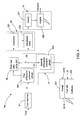
- FIG. 6 illustrates a schematic block diagram of a high temperature fuel cell system of another embodiment.
- the high temperature fuel cell system 4 similar to the high temperature fuel cell system 3 of FIG. 3 , the high temperature fuel cell system 4 according to another embodiment also includes a fuel reformer 31, a fuel cell 32, a cooler 331 and a bottoming cycle including an external or internal combustion engine 332.
- the fuel cell 32 includes an anode 321 for electrochemically oxidizing fuel and a cathode 322 for electrochemically reducing oxygen.
- the anode 321 includes an inlet 3211 and an outlet 3212.
- a splitting position Q is located in the outlet 3212 of the anode 321 of the fuel cell 32, instead of the outlet of the fuel reformer 31, and a tail gas S generated from the outlet 3212 of the anode 321 of the fuel cell 32 is regarded as the main stream.
- the tail gas S generated from the outlet 3212 of the anode 321 of the fuel cell 32 is split into a first branch stream S1 and a second branch stream S2 at the splitting position Q.
- the fuel reformer 31 mixes a fuel with the first branch stream S1 of the tail gas S from the outlet 3212 of the anode 321 of the fuel cell 32 to generate a reformed stream.
- the reformed stream is then returned to the inlet 3211 of the fuel cell 32 for high efficient power generation.
- the fuel can be for example biogas, natural gas, liquefied petroleum gas, methane, ethane, propane, methanol, ethanol, syngas, and other hydrocarbon fuels.
- the second branch stream S2 of the tail gas S is diverted to the cooler 331.
- the cooler 331 removes heat from the second branch stream S2, and the external or internal combustion engine 332 is driven to generate additional electricity for providing increased efficiency of power generation in response to the cooled second branch stream.
- the fuel cell 32 acts as the upstream device, while the fuel reformer 31 acts as the first downstream device, and the cooler 331 and the bottoming cycle including the external or internal combustion engine 332 together act as the second downstream device 33.
- measuring device 34 including the first and the second differential pressure gauge 341, 342, the controlling device 35 including the controller 351 and the adjustable valve 352 and the flow rate ratio calculator 36 as shown in FIGS. 4 and 5 and their equivalent alterations can be similarly applied to the high temperature fuel cell system 4 of FIG. 6 .
- the similar descriptions are omitted herein for purpose to language simplification.
- system for controlling the flow rate ratio of the present invention should be also not limited to the systems 3a and 3b of FIGS. 4 and 5 , in fact, the system and the method for controlling the flow rate ratio of the present invention can be applied to any proper high temperature system similar to the high temperature system 1 of FIG. 1 .
- the system and the method for controlling the flow rate ratio of the present invention can eliminate the need of correction for temperature, pressure and composition change of the stream, which has advantage of low pressure drop, low energy cost, fast response, easy maintenance and easier to scale up.
- the system and the method for controlling the flow rate ratio of the present invention can be applied to any high temperature system wherever fluid or gas properties are difficult to ascertain but an accurate flow split is required and can enable the high temperature system in terms of high energy efficiency, high reliability and flexibility, low operating cost.
Landscapes
- Engineering & Computer Science (AREA)
- Life Sciences & Earth Sciences (AREA)
- Sustainable Development (AREA)
- General Physics & Mathematics (AREA)
- Physics & Mathematics (AREA)
- General Chemical & Material Sciences (AREA)
- Chemical Kinetics & Catalysis (AREA)
- Electrochemistry (AREA)
- Chemical & Material Sciences (AREA)
- Sustainable Energy (AREA)
- Manufacturing & Machinery (AREA)
- Automation & Control Theory (AREA)
- Fuel Cell (AREA)
- Flow Control (AREA)
- Fluid Mechanics (AREA)
- Hydrogen, Water And Hydrids (AREA)
Abstract
Description
- This disclosure relates generally to high temperature application, and more particularly to a system and a method for controlling a flow rate ratio in a high temperature environment.
- In a high temperature environment, when fluid or gas properties are difficult to ascertain (for example, in the case that fluid or gas comprises multi-components) but an accurate flow split is required, it is usually impossible to measure flow rate of individual splitting flows by using flow meters, which results from complex fluid or gas properties. Because under the high temperature environment, a density of fluid or gas having complex properties depends on its temperature, pressure and composition, and the changes of fluid or gas on its temperature, pressure and composition in turn have an important influence on a flow rate of fluid or gas. So it is difficult to determine a flow rate ratio in such a circumstance.
- For example, in a high temperature fuel cell system, especially hybrid system with gas turbine, or gas engine, fast load transition and optimization of system efficiency are one key issue. A traditional way of controlling a recycle flow rate in the high temperature hybrid fuel cell system is generally by adjusting a gas driving device of the system, such as a blower or a compressor. However, it is slow due to the redistribution of pressure in a recycle loop of the high temperature hybrid fuel cell system. Furthermore, the fluctuation of differential pressure at an anode inlet of a fuel cell may affect durability and even its lifetime of the fuel cell, and the recycle flow rate may affect fuel utilization of the fuel cell and even the system efficiency. But in operation of the conventional high temperature fuel cell hybrid system, the differential pressure at the anode inlet of the fuel cell and the recycle flow rate cannot be controlled separately, due to lack of real time measurement and control of recycle flow rate ratio.
- In one aspect of the present invention, a system for controlling a flow rate ratio is provided. The system for controlling the flow rate ratio comprises: an upstream device for generating a main stream, wherein the main stream is split into a first branch stream and a second branch stream at a splitting position; a first downstream device to which the first branch stream is diverted, wherein both the upstream device and the first downstream device operate at a high temperature which is larger than 300°C; a second downstream device to which the second branch stream is diverted; a measuring device for measuring differential pressures of two of the main stream, the first branch stream and the second branch stream; and a controlling device for controlling a flow rate ratio of the first branch stream to the main stream in real time in response to the measured differential pressures.
- In another aspect of the present invention, a method for controlling a flow rate ratio using the above system is also provided. The method for controlling the flow rate ratio comprises: a1) measuring real time differential pressures of two of the main stream, the first branch stream and the second branch stream; a2) calculating a flow rate ratio of the first branch stream to the main stream in real time with the measured differential pressures; a3) comparing the calculated flow rate ratio to a user-defined target flow rate ratio; and a4) controlling a flow rate of at least one of the first branch stream and the second branch stream in real time with the compared result.
- In still another aspect of the present invention, a system for controlling a recycle flow rate ratio is also provided. The system for controlling the recycle flow rate ratio comprises: a fuel cell comprising an anode for generating a tail gas, the anode comprising an inlet and an outlet; a fuel reformer for mixing a fuel with the tail gas from the outlet of the fuel cell to generate a reformed stream, wherein the reformed stream is split into a first branch stream and a second branch stream at a splitting position, and the first branch stream is returned to the inlet of the anode of the fuel cell for power generation; a cooler for removing heat from the second branch stream; a bottoming cycle including an external or internal combustion engine driven in response to the cooled second branch stream; a measuring device for measuring differential pressures of two of the main stream, the first branch stream and the second branch stream; and a controlling device for controlling a flow rate ratio of the first branch stream to the main stream in real time in response to the measured differential pressures.
- These and other features, aspects, and advantages of the present disclosure will become better understood when the following detailed description is read with reference to the accompanying drawings in which like characters represent like parts throughout the drawings, wherein:
-
FIG. 1 is a schematic block diagram of a high temperature system; -
FIG. 2 is a schematic block diagram of a high temperature recycle system; -
FIG. 3 is a schematic block diagram of a high temperature fuel cell system in accordance with an embodiment; -
FIG. 4 is a schematic block diagram of a system for controlling a flow rate ratio based onFIG. 3 in accordance with a first embodiment of the present invention; -
FIG. 5 is a schematic block diagram of a system for controlling a flow rate ratio based onFIG. 3 in accordance with a second embodiment of the present invention; -
FIG. 6 is a schematic block diagram of a high temperature fuel cell system in accordance with another embodiment; -
FIG. 7 is a flowchart of a method for controlling a flow rate ratio in accordance with an embodiment of the present invention; and -
FIG. 8 is a schematic diagram used in determining a calibrated coefficient for a measuring device of the present invention. - Embodiments of the present disclosure will be described hereinbelow with reference to the accompanying drawings. In the following description, well-known functions or constructions are not described in detail to avoid obscuring the disclosure in unnecessary detail.
- Unless defined otherwise, technical and scientific terms used herein have the same meaning as is commonly understood by one of ordinary skill in the art to which this disclosure belongs. The terms "first", "second", and the like, as used herein do not denote any order, quantity, or importance, but rather are used to distinguish one element from another. Also, the terms "a" and "an" do not denote a limitation of quantity, but rather denote the presence of at least one of the referenced items. The term "or" is meant to be inclusive and mean either or all of the listed items. The use of "including," "comprising" or "having" and variations thereof herein are meant to encompass the items listed thereafter and equivalents thereof as well as additional items.
-
FIG. 1 illustrates a schematic block diagram of an embodiment of a high temperature system. As shown inFIG. 1 , thehigh temperature system 1 according to the embodiment includes anupstream device 11, a firstdownstream device 12 and a seconddownstream device 13. Both theupstream device 11 and the firstdownstream device 12 operate at a high temperature which is larger than 300°C. Theupstream device 11 generates a main stream S which is split into a first branch stream S1 and a second branch stream S2 at a splitting position Q. The main stream S has complex fluid or gas properties, for example, the main stream S can be fluid or gas having multi-components. The first branch stream S1 is diverted to the firstdownstream device 12 and is correspondingly processed in the firstdownstream device 12. The second branch stream S2 is diverted to the seconddownstream device 13 and is correspondingly processed in the seconddownstream device 13. - In order to measure and control a flow rate ratio RR of the first branch stream S1 to the main stream S in real time in the
high temperature system 1, on the basis of components of thehigh temperature system 1, a system for controlling a flow rate ratio further includes a measuring device and a controlling device (both of which are not shown inFIG. 1 ). The measuring device measures real time differential pressures DP1, DP2 of two of the main stream S, the first branch stream S1 and the second branch stream S2. The controlling device controls the flow rate ratio RR of the firstbranch stream S 1 to the main stream S in real time in response to the measured differential pressures DP1, DP2. -
FIG. 7 illustrates a flowchart of a method for controlling a flow rate ratio using the above system in accordance with an embodiment of the present invention. As shown inFIG. 7 , a method for controlling a flow rate ratio using the above system in accordance with an embodiment of the present invention comprises the steps as following: - At block s1, real time differential pressures DP1, DP2 of two of the main stream S, the first branch stream S1 and the second branch stream S2 in the above system are measured.
- At block s2, a flow rate ratio RR of the first
branch stream S 1 to the main stream S is calculated in real time with the measured differential pressures DP1, DP2. - At block s3, the calculated flow rate ratio RR is compared to a user-defined target flow rate ratio.
- At block s4, a flow rate of at least one of the first branch stream S1 and the second branch stream S2 in real time is controlled with the compared result.
- In one embodiment, as shown in
FIG. 7 , the method for controlling the flow rate ratio further comprises the step as following: - At block s5, a calibrated coefficient K for the
measuring device 34 is determined in advance. Therefore, at block s2, a flow rate ratio RR of the first branch stream S1 to the main stream S in real time is calculated with the measured differential pressures DP1, DP2 and the calibrated coefficient K. - As an example, the
high temperature system 1 can be a high temperature recycle system.FIG. 2 illustrates a schematic block diagram of an embodiment of a high temperature recycle system. As shown inFIG. 2 , similar to thehigh temperature system 1 ofFIG. 1 , the hightemperature recycle system 2 according to the embodiment includes anupstream device 11, a firstdownstream device 12 and a seconddownstream device 13. Both theupstream device 11 and the firstdownstream device 12 operate at a high temperature which is larger than 300°C. Theupstream device 11 generates a main stream S which is split into a first branch stream S1 and a second branch stream S2 at a splitting position Q. The main stream S has complex fluid or gas properties, for example, the main stream S can be fluid or gas having multi-components. The first branch stream S1 is diverted to the firstdownstream device 12 and is correspondingly processed in the firstdownstream device 12. The second branch stream S2 is diverted to the seconddownstream device 13 and is correspondingly processed in the seconddownstream device 13. - However, referring to
FIG. 2 , different from thehigh temperature system 1 ofFIG. 1 , in the hightemperature recycle system 2 ofFIG. 2 , at least part of the first branch stream S1 is returned to theupstream device 11 for processing after the first branch stream S1 is passed through the firstdownstream device 12, and a flow rate ratio RR of the firstbranch stream S 1 to the main stream S is a recycle flow rate ratio RR of the first branch stream S1 to the main stream S. - Similar to the
high temperature system 1 ofFIG. 1 , in order to measure and control the recycle flow rate ratio RR in real time in the hightemperature recycle system 2, on the basis of components of the hightemperature recycle system 2, a system for controlling a flow rate ratio further includes a measuring device and a controlling device (both of which are not shown inFIG. 2 ). The measuring device measures real time differential pressures DP1, DP2 of two of the main stream S, the first branch stream S1 and the second branch stream S2. The controlling device controls the recycle flow rate ratio RR in real time in response to the measured differential pressures DP1, DP2. - A high temperature fuel cell system will be hereinafter taken as an example of a high temperature system for purpose to describe a system and a method for controlling a flow rate ratio in detail.
-
FIG. 3 illustrates a schematic block diagram of a high temperature fuel cell system of an embodiment. As shown inFIG. 3 , the high temperaturefuel cell system 3 according to an embodiment includes afuel reformer 31, afuel cell 32, acooler 331 and a bottoming cycle including an external orinternal combustion engine 332. Thefuel cell 32 which is for example a solid oxide fuel cell (SOFC) includes ananode 321 for electrochemically oxidizing fuel and acathode 322 for electrochemically reducing oxygen. Theanode 321 includes aninlet 3211 and anoutlet 3212. - With reference to
FIG. 3 , a splitting position Q is located in an outlet of thefuel reformer 31. Thefuel reformer 31 mixes a fuel with a tail gas generated from theoutlet 3212 of theanode 321 of thefuel cell 32 and the fuel and the tail gas are reformed in thefuel reformer 32 to generate a reformed stream S as the main stream. The fuel can be for example biogas, natural gas, liquefied petroleum gas, methane, ethane, propane, methanol, ethanol, syngas, and other hydrocarbon fuels. In thefuel reformer 31, the hydrocarbon fuel is reformed into hydrogen (H2) and carbon monoxide (CO) by reforming reaction and at the same time, carbon monoxide and steam (H2O) is also transformed into carbon dioxide (CO2) and hydrogen by transformation reaction. The reformed stream S includes multi-components, for example, the reformed stream S has mixed gas composition of hydrogen, carbon monoxide, carbon dioxide, methane (CH4), steam and etc. The reformed stream S is split into a first branch stream S1 and a second branch stream S2 at the splitting position Q. The first branch stream S1 is diverted to theinlet 3211 of theanode 321 of thefuel cell 32 for high efficient power generation. Typically, thefuel cell 32 converts hydrogen and oxygen into water to produce electricity and heat. The byproduct water may exit from theoutlet 3212 of thefuel cell 32 as steam in high temperature operations. The second branch stream S2 is diverted to the cooler 331. The cooler 331 removes heat from the second branch stream S2, and the external orinternal combustion engine 332 is driven to generate additional electricity for providing increased efficiency of power generation in response to the cooled second branch stream, and the redundant portion is discharged as an exhaust from the external orinternal combustion engine 332. The steam reforming reaction of hydrocarbons in thefuel reformer 31 is typically endothermic, and therefore, the reforming may utilize the heat generated by the typically exothermic electrochemical reactions of thefuel cell 32. - In the high temperature
fuel cell system 3 ofFIG. 3 , thefuel reformer 31 acts as the upstream device, while thefuel cell 32 acts as the first downstream device, and the cooler 331 and the bottoming cycle including the external orinternal combustion engine 332 together act as the seconddownstream device 33. -
FIG. 4 illustrates a schematic block diagram of a system for controlling a flow rate ratio based onFIG. 3 in accordance with a first embodiment of the present invention. As shown inFIG. 4 , on the basis of components of the high temperaturefuel cell system 3 ofFIG. 3 , asystem 3a for controlling a flow rate ratio according to a first embodiment of the present invention further includes a measuringdevice 34 and a controllingdevice 35. The measuringdevice 34 measures differential pressures of two of the main stream S, the first branch stream S1 and the second branch stream S2. The controllingdevice 35 controls a flow rate ratio of the firstbranch stream S 1 to the main stream S in real time in response to the measured differential pressures. The measuringdevice 34 includes first and seconddifferential pressure gauges differential pressure gauges differential pressure gauges differential pressure gauge 341 is located between thefuel reformer 31 as the upstream device and the splitting position Q for measuring a differential pressure DP1 of the main stream S, and the seconddifferential pressure gauge 342 is located between thefuel cell 32 as the first downstream device and the splitting position Q for measuring a differential pressure DP2 of the firstbranch stream S 1. - With reference to
FIG. 4 , thesystem 3a for controlling the flow rate ratio further includes a flowrate ratio calculator 36. A calibrated coefficient K for the measuring device 34 (that is, a calibrated coefficient K for the seconddifferential pressure gauge 342 relative to the first differential pressure gauge 341) is pre-stored in the flowrate ratio calculator 36. The flowrate ratio calculator 36 calculates the flow rate ratio based on the measured differential pressures and the calibrated coefficient. -
FIG. 8 illustrates a schematic diagram used in determining the calibrated coefficient K for the measuringdevice 34. As shown inFIG. 8 , avariable gas source 81 is firstly prepared. Thevariable gas source 81 is connected to a massflow rate controller 82, and the massflow rate controller 82 is then connected with the first and the seconddifferential pressure gauges device 34. Gas flow rate of the massflow rate controller 82 is changed and then, first and second differential pressure values DPc1, DPc2 of the first and the seconddifferential pressure gauges device 33 is determined using the following equations:


- Wherein F represents the gas flow rate of the mass
flow rate controller 82, F1 and F2 respectively represent gas flow rate of the first and the second pressure gauges 341 and 342, K1 and K2 respectively represent first and second coefficients of the first and the seconddifferential pressure gauges variable gas source 81. - The flow rate ratio RR of the first
branch stream S 1 to the main stream S is calculated using the following equations:


- Wherein ρ1 represents a density of the first branch stream S1 and ρ represents a density of the main stream S.
- From the equations (5)-(8), the flow rate ratio RR of the first branch stream S1 to the main stream S may be obtained as following:

- The controlling
device 35 includes acontroller 351 and anadjustable valve 352 for adjusting a flow rate. Thecontroller 351 receives the flow rate ratio RR calculated from the flowrate ratio calculator 36, compares the calculated flow rate ratio RR to a user-defined target flow rate ratio and controls an opening position of theadjustable valve 352 based on the compared result. In detail, thecontroller 351 sends out a control signal to theadjustable valve 352 based on an error between the target flow rate ratio and the calculated flow rate ratio RR, and theadjustable valve 352 receives the control signal from thecontroller 351 and adjusts its opening position to control a flow rate of at least one of the first branch stream S1 and the second branch stream S2. In one embodiment, as shown inFIG. 4 , theadjustable valve 352 is arranged between the splitting position Q and the seconddownstream device 33 for adjusting a flow rate of the second branch stream S2. Theadjustable valve 352 is not limited to such an arrangement, for example, in another embodiment, theadjustable valve 352 may be also a three-way valve which is arranged at the splitting position Q for adjusting flow rates of the first and the second branch streams S1, S2. -
FIG. 5 illustrates a schematic block diagram of a system for controlling a flow rate ratio based onFIG. 3 in accordance with a second embodiment of the present invention. As shown inFIG. 5 , on the basis of components of the high temperaturefuel cell system 3 ofFIG. 3 , asystem 3b for controlling a flow rate ratio according to a second embodiment of the present invention further includes a measuringdevice 34 and a controllingdevice 35. The measuringdevice 34 measures differential pressures of two of the main stream S, the first branch stream S1 and the second branch stream S2. The controllingdevice 35 controls a flow rate ratio of the first branch stream S1 to the main stream S in real time in response to the measured differential pressures. The measuringdevice 34 includes first and seconddifferential pressure gauges differential pressure gauges differential pressure gauges differential pressure gauge 341 is located between the splitting position Q and the seconddownstream device 33 for measuring a differential pressure DP1 of the second branch stream S2, and the seconddifferential pressure gauge 342 is located between thefuel cell 32 as the first downstream device and the splitting position Q for measuring a differential pressure DP2 of the firstbranch stream S 1. - With reference to
FIG. 5 , thesystem 3b for controlling the flow rate ratio further includes a flowrate ratio calculator 36. A calibrated coefficient K for the measuring device 34 (that is, a calibrated coefficient K for the seconddifferential pressure gauge 342 relative to the firstdifferential pressure gauge 341, as shown in equation (4)) is pre-stored in the flowrate ratio calculator 36. The calibrated coefficient K for the measuringdevice 34 can be determined by using the above method with reference toFIG. 8 . The flowrate ratio calculator 36 calculates the flow rate ratio RR based on the measured differential pressures DP1, DP2 and the calibrated coefficient K. - The flow rate ratio RR of the first
branch stream S 1 to the main stream S is calculated using the following equations:


- Wherein ρ2 represents a density of the first branch stream S1 and ρ1 represents a density of the second branch stream S2.
- From the equations (10)-(13), the flow rate ratio RR of the first
branch stream S 1 to the main stream S may be obtained as following:
- The controlling
device 35 includes acontroller 351 and anadjustable valve 352 for adjusting a flow rate. Thecontroller 351 receives the flow rate ratio calculated from the flowrate ratio calculator 36, compares the calculated flow rate ratio to a user-defined target flow rate ratio and controls an opening position of theadjustable valve 352 based on the compared result. In detail, thecontroller 351 sends out a control signal to theadjustable valve 352 based on an error between the target flow rate ratio and the calculated flow rate ratio RR, and theadjustable valve 352 receives the control signal from thecontroller 351 and adjusts its opening position to control a flow rate of at least one of the first branch stream S1 and the second branch stream S2. In one embodiment, as shown inFIG. 5 , theadjustable valve 352 may be a three-way valve which is arranged at the splitting position Q for adjusting flow rates of the first and the second branch streams S1, S2. Theadjustable valve 352 is not limited to such an arrangement, for example, in another embodiment, theadjustable valve 352 may be also arranged between the splitting position Q and the seconddownstream device 33 for adjusting a flow rate of the second branch stream S2. - In the
system differential pressure gauge device 34 makes the measurement of the flow rate ratio RR independent of the change of temperature, pressure and composition of the stream, and the complex properties of the stream have no influence on the measurement of the flow rate ratio RR, so the flow rate ratio RR can be accurately measured. Furthermore, the accurate measurement of flow rate ratio RR can optimize system control. The efficiency and lifetime of thefuel cell 32 can be promised, which will increase the total efficiency of the system and reduce the operating cost. -
FIG. 6 illustrates a schematic block diagram of a high temperature fuel cell system of another embodiment. As shown inFIG. 6 , similar to the high temperaturefuel cell system 3 ofFIG. 3 , the high temperaturefuel cell system 4 according to another embodiment also includes afuel reformer 31, afuel cell 32, a cooler 331 and a bottoming cycle including an external orinternal combustion engine 332. Thefuel cell 32 includes ananode 321 for electrochemically oxidizing fuel and acathode 322 for electrochemically reducing oxygen. Theanode 321 includes aninlet 3211 and anoutlet 3212. - However, with reference to
FIG. 6 , different from the high temperaturefuel cell system 3 ofFIG. 3 , in the high temperaturefuel cell system 4 ofFIG. 6 , a splitting position Q is located in theoutlet 3212 of theanode 321 of thefuel cell 32, instead of the outlet of thefuel reformer 31, and a tail gas S generated from theoutlet 3212 of theanode 321 of thefuel cell 32 is regarded as the main stream. The tail gas S generated from theoutlet 3212 of theanode 321 of thefuel cell 32 is split into a first branch stream S1 and a second branch stream S2 at the splitting position Q. Thefuel reformer 31 mixes a fuel with the first branch stream S1 of the tail gas S from theoutlet 3212 of theanode 321 of thefuel cell 32 to generate a reformed stream. The reformed stream is then returned to theinlet 3211 of thefuel cell 32 for high efficient power generation. The fuel can be for example biogas, natural gas, liquefied petroleum gas, methane, ethane, propane, methanol, ethanol, syngas, and other hydrocarbon fuels. The second branch stream S2 of the tail gas S is diverted to the cooler 331. The cooler 331 removes heat from the second branch stream S2, and the external orinternal combustion engine 332 is driven to generate additional electricity for providing increased efficiency of power generation in response to the cooled second branch stream. - In the high temperature
fuel cell system 4 ofFIG. 6 , thefuel cell 32 acts as the upstream device, while thefuel reformer 31 acts as the first downstream device, and the cooler 331 and the bottoming cycle including the external orinternal combustion engine 332 together act as the seconddownstream device 33. - Arrangements of the measuring
device 34 including the first and the seconddifferential pressure gauge device 35 including thecontroller 351 and theadjustable valve 352 and the flowrate ratio calculator 36 as shown inFIGS. 4 and5 and their equivalent alterations can be similarly applied to the high temperaturefuel cell system 4 ofFIG. 6 . Thus, the similar descriptions are omitted herein for purpose to language simplification. - In addition, the system for controlling the flow rate ratio of the present invention should be also not limited to the
systems FIGS. 4 and5 , in fact, the system and the method for controlling the flow rate ratio of the present invention can be applied to any proper high temperature system similar to thehigh temperature system 1 ofFIG. 1 . - The system and the method for controlling the flow rate ratio of the present invention can eliminate the need of correction for temperature, pressure and composition change of the stream, which has advantage of low pressure drop, low energy cost, fast response, easy maintenance and easier to scale up. The system and the method for controlling the flow rate ratio of the present invention can be applied to any high temperature system wherever fluid or gas properties are difficult to ascertain but an accurate flow split is required and can enable the high temperature system in terms of high energy efficiency, high reliability and flexibility, low operating cost.
- While the disclosure has been illustrated and described in typical embodiments, it is not intended to be limited to the details shown, since various modifications and substitutions can be made without departing in any way from the scope of the claims. As such, further modifications and equivalents of the disclosure herein disclosed may occur to persons skilled in the art using no more than routine experimentation, and all such modifications and equivalents are believed to be within the scope of the disclosure as defined by the following claims.
- Various aspects and embodiments of the present invention are defined by the following numbered clauses:
- 1. A system for controlling a flow rate ratio, comprising:
- an upstream device for generating a main stream, wherein the main stream is split into a first branch stream and a second branch stream at a splitting position;
- a first downstream device to which the first branch stream is diverted, wherein both the upstream device and the first downstream device operate at a high temperature which is larger than 300□;
- a second downstream device to which the second branch stream is diverted;
- a measuring device for measuring differential pressures of two of the main stream, the first branch stream and the second branch stream; and
- a controlling device for controlling a flow rate ratio of the first branch stream to the main stream in real time in response to the measured differential pressures.
- 2. The system according to
clause 1, wherein the measuring device comprises first and second differential pressure gauges which are the same and are both placed close to the splitting position. - 3. The system according to any preceding clause, wherein the first differential pressure gauge is located between the upstream device and the splitting position for measuring a differential pressure of the main stream, and the second differential pressure gauge is located between the first downstream device and the splitting position for measuring a differential pressure of the first branch stream.
- 4. The system of any preceding clause, wherein the first differential pressure gauge is located between the splitting position and the second downstream device for measuring a differential pressure of the second branch stream, and the second differential pressure gauge is located between the first downstream device and the splitting position for measuring a differential pressure of the first branch stream.
- 5. The system of any preceding clause, further comprising:
- a flow rate ratio calculator in which a calibrated coefficient for the second differential pressure gauge relative to the first differential pressure gauge is pre-stored, and wherein the flow rate ratio calculator is for calculating the flow rate ratio based on the measured differential pressures and the calibrated coefficient.
- 6. The system of any preceding clause, wherein the controlling device comprises a controller and an adjustable valve for adjusting a flow rate, the controller is for receiving the flow rate ratio calculated from the flow rate ratio calculator, comparing the calculated flow rate ratio to a user-defined target flow rate ratio and controlling an opening position of the adjustable valve based on the compared result.
- 7. The system of any preceding clause, wherein the adjustable valve is arranged between the splitting position and the second downstream device for adjusting a flow rate of the second branch stream, or the adjustable valve is a three-way valve which is arranged at the splitting position for adjusting flow rates of the first and the second branch streams.
- 8. The system of any preceding clause, wherein at least part of the first branch stream is returned to the upstream device after the first branch stream is passed through the first downstream device, and the flow rate ratio is a recycle flow rate ratio.
- 9. The system of any preceding clause, wherein the first downstream device is a fuel cell comprising an anode for generating a tail gas, the anode comprising an inlet and an outlet, and the upstream device is a fuel reformer for mixing a fuel with the tail gas from the outlet of the fuel cell to generate a reformed stream as the main stream.
- 10. The system of any preceding clause, wherein the second downstream device comprises:
- a cooler for removing heat from the second branch stream; and
- a bottoming cycle comprising an external or internal combustion engine driven in response to the cooled second branch stream.
- 11. The system of any preceding clause, wherein the upstream device is a fuel cell comprising an anode for generating a tail gas as the main stream, the anode comprising an inlet and an outlet, and the first downstream device is a fuel reformer for mixing a fuel with the first branch stream of the tail gas from the outlet of the fuel cell to generate a reformed stream.
- 12. A method for controlling a flow rate ratio using the system according to any preceding clause, comprising:
- a1) measuring real time differential pressures of two of the main stream, the first branch stream and the second branch stream;
- a2) calculating a flow rate ratio of the first branch stream to the main stream in real time with the measured differential pressures;
- a3) comparing the calculated flow rate ratio to a user-defined target flow rate ratio; and
- a4) controlling a flow rate of at least one of the first branch stream and the second branch stream in real time with the compared result.
- 13. The method according to any preceding clause, further comprising:
- determining a calibrated coefficient for the measuring device in advance; wherein the step a2) comprises calculating a flow rate ratio of the first branch stream to the main stream in real time with the measured differential pressures and the calibrated coefficient.
- 14. The method according to any preceding clause, wherein the measuring device comprises first and second differential pressure gauges which are the same and are both placed close to the splitting position, determining the calibrated coefficient for the measuring device in advance comprising:
- preparing a variable gas source;
- connecting the variable gas source to a mass flow rate controller;
- connecting the mass flow rate controller with the first and the second differential pressure gauges;
- changing a gas flow rate of the mass flow rate controller;
- recording first and second differential pressure values of the first and the second differential pressure gauges respectively; and
- determining the calibrated coefficient using the following equations:


wherein F represents the gas flow rate of the mass flow rate controller, K represents the calibrated coefficient, DPc1 and DPc2 represent respectively the first and the second differential pressure values of the first and the second differential pressure gauges, K1 and K2 represent respectively first and second coefficients of the first and the second differential pressure gauges, and ρc represents a gas density of the variable gas source.
- 15. The method according to any preceding clause, wherein the step a1) comprises:
- measuring a differential pressure of the main stream using the first differential pressure gauge located between the upstream device and the splitting position; and
- measuring a differential pressure of the first branch stream using the second differential pressure gauge located between the first downstream device and the splitting position.
- 16. The method according to any preceding clause, wherein the step a2) comprises:
- calculating a flow rate ratio of the first branch stream to the main stream using the following equations:

wherein RR represents the flow rate ratio, DP1 represents the differential pressure of the main stream and DP2 represents the differential pressure of the first branch stream.
- calculating a flow rate ratio of the first branch stream to the main stream using the following equations:
- 17. The method according to any preceding clause, wherein the step a1) comprises:
- measuring a differential pressure of the second branch stream using the first differential pressure gauge located between the splitting position and the second downstream device; and
- measuring a differential pressure of the first branch stream using the second differential pressure gauge located between the first downstream device and the splitting position.
- 18. The method according to any preceding clause, wherein the step a2) comprises:
- calculating a flow rate ratio of the first branch stream to the main stream using the following equations:

wherein RR represents the flow rate ratio, DP1 represents the differential pressure of the second branch stream and DP2 represents the differential pressure of the first branch stream.
- calculating a flow rate ratio of the first branch stream to the main stream using the following equations:
- 19. The method according to any preceding clause, wherein the controlling device comprises a controller and an adjustable valve for adjusting a flow rate, the step a4) comprising:
- the controller sending out a control signal to the adjustable valve based on an error between the target flow rate ratio and the calculated flow rate ratio; and
- the adjustable valve receiving the control signal from the controller and adjusting its opening position to control a flow rate of at least one of the first branch stream and the second branch stream.
- 20. A system for controlling a recycle flow rate ratio, comprising:
- a fuel cell comprising an anode for generating a tail gas, the anode comprising an inlet and an outlet;
- a fuel reformer for mixing a fuel with the tail gas from the outlet of the fuel cell to generate a reformed stream, wherein the reformed stream is split into a first branch stream and a second branch stream at a splitting position, and the first branch stream is returned to the inlet of the anode of the fuel cell for power generation;
- a cooler for removing heat from the second branch stream;
- a bottoming cycle including an external or internal combustion engine driven in response to the cooled second branch stream;
- a measuring device for measuring differential pressures of two of the main stream, the first branch stream and the second branch stream; and
- a controlling device for controlling a flow rate ratio of the first branch stream to the main stream in real time in response to the measured differential pressures.
Claims (15)
- A system (1) for controlling a flow rate ratio, comprising:an upstream device (11) for generating a main stream (S), wherein the main stream (S) is split into a first branch stream (S1) and a second branch stream (S2) at a splitting position (Q);a first downstream device (12) to which the first branch stream (S1) is diverted, wherein both the upstream device (11) and the first downstream device (12) operate at a high temperature which is larger than 300°C;a second downstream device (13) to which the second branch stream (S2) is diverted;a measuring device for measuring differential pressures of two of the main stream, the first branch stream and the second branch stream; anda controlling device for controlling a flow rate ratio of the first branch stream to the main stream in real time in response to the measured differential pressures.
- The system (1) according to claim 1, wherein the measuring device comprises first and second differential pressure gauges which are the same and are both placed close to the splitting position (Q).
- The system (1) according to claim 2, wherein the first differential pressure gauge is located between the upstream device (11) and the splitting position (Q) for measuring a differential pressure of the main stream (S), and the second differential pressure gauge is located between the first downstream device (12) and the splitting position (Q) for measuring a differential pressure of the first branch stream (S1).
- The system (1) of either of claims 2 or 3, wherein the first differential pressure gauge is located between the splitting position (Q) and the second downstream device (12) for measuring a differential pressure of the second branch stream (S2), and the second differential pressure gauge is located between the first downstream device (12) and the splitting position (Q) for measuring a differential pressure of the first branch stream (S1).
- The system (1) of any of claims 2 to 4, further comprising:a flow rate ratio calculator in which a calibrated coefficient for the second differential pressure gauge relative to the first differential pressure gauge is pre-stored, and wherein the flow rate ratio calculator is for calculating the flow rate ratio based on the measured differential pressures and the calibrated coefficient.
- The system (1) of claim 5, wherein the controlling device comprises a controller and an adjustable valve for adjusting a flow rate, the controller is for receiving the flow rate ratio calculated from the flow rate ratio calculator, comparing the calculated flow rate ratio to a user-defined target flow rate ratio and controlling an opening position of the adjustable valve based on the compared result.
- The system (1) of claim 6, wherein the adjustable valve is arranged between the splitting position (Q) and the second downstream device (13) for adjusting a flow rate of the second branch stream (S2), or the adjustable valve is a three-way valve which is arranged at the splitting position (Q) for adjusting flow rates of the first and the second branch streams (S1, S2).
- The system (1) of any preceding claim, wherein at least part of the first branch stream (S1) is returned to the upstream device (11) after the first branch stream (S1) is passed through the first downstream device (12), and the flow rate ratio is a recycle flow rate ratio.
- The system (1) of claim 8, wherein the first downstream device (12) is a fuel cell comprising an anode for generating a tail gas, the anode comprising an inlet and an outlet, and the upstream device (11) is a fuel reformer for mixing a fuel with the tail gas from the outlet of the fuel cell to generate a reformed stream as the main stream (S).
- The system (1) of claim 9, wherein the second downstream device (13) comprises:a cooler for removing heat from the second branch stream (S2); anda bottoming cycle comprising an external or internal combustion engine driven in response to the cooled second branch stream (S2).
- The system (1) of any of claims 8 to 10, wherein the upstream device (11) is a fuel cell comprising an anode for generating a tail gas as the main stream (S), the anode comprising an inlet and an outlet, and the first downstream device (12) is a fuel reformer for mixing a fuel with the first branch stream (S1) of the tail gas from the outlet of the fuel cell to generate a reformed stream.
- A method for controlling a flow rate ratio using the system (1) according to claim 1, comprising:a1) measuring real time differential pressures of two of the main stream (S), the first branch stream (S1) and the second branch stream (S2);a2) calculating a flow rate ratio of the first branch stream (S1) to the main stream (S) in real time with the measured differential pressures;a3) comparing the calculated flow rate ratio to a user-defined target flow rate ratio; anda4) controlling a flow rate of at least one of the first branch stream (S1) and the second branch stream (S2) in real time with the compared result.
- The method according to claim 12, further comprising:determining a calibrated coefficient for the measuring device in advance; wherein the step a2) comprises calculating a flow rate ratio of the first branch stream (S1) to the main stream in real time with the measured differential pressures and the calibrated coefficient.
- The method according to claim 13, wherein the measuring device comprises first and second differential pressure gauges which are the same and are both placed close to the splitting position, determining the calibrated coefficient for the measuring device in advance comprising:preparing a variable gas source;connecting the variable gas source to a mass flow rate controller;connecting the mass flow rate controller with the first and the second differential pressure gauges;changing a gas flow rate of the mass flow rate controller;recording first and second differential pressure values of the first and the second differential pressure gauges respectively; anddetermining the calibrated coefficient using the following equations:


wherein F represents the gas flow rate of the mass flow rate controller, K represents the calibrated coefficient, DPc1 and DPc2 represent respectively the first and the second differential pressure values of the first and the second differential pressure gauges, K1 and K2 represent respectively first and second coefficients of the first and the second differential pressure gauges, and ρc represents a gas density of the variable gas source. - The method according to claim 14, wherein the step a1) comprises:measuring a differential pressure of the main stream using the first differential pressure gauge located between the upstream device and the splitting position; andmeasuring a differential pressure of the first branch stream using the second differential pressure gauge located between the first downstream device and the splitting position.
Applications Claiming Priority (1)
| Application Number | Priority Date | Filing Date | Title |
|---|---|---|---|
| CN201410525550.5A CN105576268B (en) | 2014-10-08 | 2014-10-08 | System and method for controlling flow ratio |
Publications (3)
| Publication Number | Publication Date |
|---|---|
| EP3007026A2 true EP3007026A2 (en) | 2016-04-13 |
| EP3007026A3 EP3007026A3 (en) | 2016-05-25 |
| EP3007026B1 EP3007026B1 (en) | 2018-09-26 |
Family
ID=54291023
Family Applications (1)
| Application Number | Title | Priority Date | Filing Date |
|---|---|---|---|
| EP15187115.9A Active EP3007026B1 (en) | 2014-10-08 | 2015-09-28 | System and method for controlling flow rate ratio |
Country Status (5)
| Country | Link |
|---|---|
| US (1) | US10305125B2 (en) |
| EP (1) | EP3007026B1 (en) |
| JP (1) | JP6749748B2 (en) |
| KR (1) | KR102321201B1 (en) |
| CN (1) | CN105576268B (en) |
Families Citing this family (7)
| Publication number | Priority date | Publication date | Assignee | Title |
|---|---|---|---|---|
| JP6109529B2 (en) * | 2012-10-31 | 2017-04-05 | 三菱日立パワーシステムズ株式会社 | Power generation system |
| AT517685B1 (en) * | 2015-11-17 | 2017-04-15 | Avl List Gmbh | Measuring method and measuring device for determining the recirculation rate |
| JP6213602B2 (en) | 2016-04-05 | 2017-10-18 | 住友電気工業株式会社 | Sensor module and wireless sensor device |
| CN107464944B (en) | 2016-05-27 | 2021-02-02 | 通用电气公司 | Fuel cell system and method of operating the same |
| CN111725545A (en) * | 2020-06-29 | 2020-09-29 | 潍柴动力股份有限公司 | A kind of control method, device and FCU of SOFC system |
| US11747053B2 (en) * | 2021-06-10 | 2023-09-05 | Johnson Controls Technology Company | Reheat operation for heat pump system |
| CN117829035B (en) * | 2024-03-05 | 2024-05-14 | 南昌工程学院 | A method for predicting flow in downstream branch channels of T-shaped open channels |
Family Cites Families (22)
| Publication number | Priority date | Publication date | Assignee | Title |
|---|---|---|---|---|
| JPS602606B2 (en) | 1979-11-10 | 1985-01-23 | 株式会社東芝 | Core recirculation flow measurement device |
| DE3673175D1 (en) | 1985-01-10 | 1990-09-13 | Atlas Fahrzeugtechnik Gmbh | MIXTURE CONTROL DEVICE FOR AN INTERNAL COMBUSTION ENGINE. |
| JPS62222571A (en) * | 1986-03-25 | 1987-09-30 | Tokyo Electric Power Co Inc:The | Fuel cell power generating plant |
| JPH0769315B2 (en) | 1992-04-06 | 1995-07-26 | 株式会社島津製作所 | Gas chromatograph |
| DE59710962D1 (en) * | 1997-08-15 | 2003-12-11 | Alstom Switzerland Ltd | Pipe system for the controlled distribution of a flowing medium and method for operating such a pipe system |
| JPH11233129A (en) | 1998-02-17 | 1999-08-27 | Mitsubishi Heavy Ind Ltd | Solid electrolyte fuel cell generating system |
| US7097925B2 (en) * | 2000-10-30 | 2006-08-29 | Questair Technologies Inc. | High temperature fuel cell power plant |
| JP3856730B2 (en) | 2002-06-03 | 2006-12-13 | 東京エレクトロン株式会社 | A gas diversion supply method to a chamber from a gas supply facility provided with a flow rate control device. |
| JP4055639B2 (en) * | 2003-04-28 | 2008-03-05 | トヨタ自動車株式会社 | Operation control of power supply system with fuel cell |
| US8034183B2 (en) * | 2005-02-02 | 2011-10-11 | Tokyo Electron Limited | Cleaning method and plasma processing method |
| US7562588B2 (en) | 2006-04-27 | 2009-07-21 | Delphi Technologies, Inc. | Method and apparatus for controlling mass flow rate of recycled anode tail gas in solid oxide fuel cell system |
| US20070278161A1 (en) | 2006-05-31 | 2007-12-06 | Holloman Corporation | Waste Sludge Sanitizing Process Utilizing Biosolids Recycle |
| US8019481B2 (en) * | 2006-12-12 | 2011-09-13 | Horiba Stec, Co., Ltd. | Flow rate ratio control device |
| JP2009054404A (en) * | 2007-08-27 | 2009-03-12 | Denso Corp | Fuel cell system |
| DE102007062097A1 (en) | 2007-12-21 | 2009-06-25 | Mahle International Gmbh | Diagnostic procedure for additional valves |
| US20100269924A1 (en) * | 2007-12-27 | 2010-10-28 | Horiba Stec, Co., Ltd. | Flow rate ratio controlling apparatus |
| JP2012079410A (en) * | 2010-09-30 | 2012-04-19 | Toto Ltd | Fuel cell device |
| US20140060461A1 (en) * | 2011-03-31 | 2014-03-06 | General Electric Company | Power generation system utilizing a fuel cell integrated with a combustion engine |
| US20120251899A1 (en) * | 2011-03-31 | 2012-10-04 | General Electric Company | Solid-oxide fuel cell high-efficiency reform-and-recirculate system |
| FI123857B (en) | 2012-02-10 | 2013-11-29 | Convion Oy | Method and apparatus for utilizing recirculation in a high temperature fuel cell system |
| CN202687941U (en) | 2012-06-12 | 2013-01-23 | 佛山市海卓瑞流体控制工程有限公司 | Variable frequency oil gas recycling control system of fueling machine |
| US9029036B2 (en) * | 2012-10-25 | 2015-05-12 | GM Global Technology Operations LLC | Systems and methods for controlling a compressor recirculation valve |
-
2014
- 2014-10-08 CN CN201410525550.5A patent/CN105576268B/en active Active
-
2015
- 2015-09-28 EP EP15187115.9A patent/EP3007026B1/en active Active
- 2015-10-01 JP JP2015195526A patent/JP6749748B2/en active Active
- 2015-10-02 KR KR1020150139116A patent/KR102321201B1/en active Active
- 2015-10-06 US US14/876,438 patent/US10305125B2/en active Active
Non-Patent Citations (1)
| Title |
|---|
| None |
Also Published As
| Publication number | Publication date |
|---|---|
| US10305125B2 (en) | 2019-05-28 |
| JP6749748B2 (en) | 2020-09-02 |
| EP3007026A3 (en) | 2016-05-25 |
| CN105576268A (en) | 2016-05-11 |
| KR102321201B1 (en) | 2021-11-04 |
| US20160104906A1 (en) | 2016-04-14 |
| KR20160041783A (en) | 2016-04-18 |
| EP3007026B1 (en) | 2018-09-26 |
| JP2016076213A (en) | 2016-05-12 |
| CN105576268B (en) | 2019-02-15 |
Similar Documents
| Publication | Publication Date | Title |
|---|---|---|
| US10305125B2 (en) | System and method for controlling flow rate ratio | |
| US20150086888A1 (en) | Method for determining composition of gas fuel, device for determining composition of gas fuel, fuel supply system, and fuel cell system | |
| US20140342257A1 (en) | Fuel supply system, fuel cell system, and method for running each | |
| US20140377678A1 (en) | Fuel supply system, fuel cell system, and method for running each | |
| US6884533B2 (en) | Utilization based power plant control system | |
| US6752968B2 (en) | Reformer controlling apparatus | |
| EP2847816B1 (en) | Method of operating a fuel cell power system | |
| US20120156575A1 (en) | Flow estimation based on anode pressure response in fuel cell system | |
| US20060269804A1 (en) | Fuel cell power generation system method of detecting degree of deterioration of reformer therefor and fuel cell power generation method | |
| CN216976520U (en) | Mixed gas transmission and distribution system for natural gas and hydrogen | |
| US20110183225A1 (en) | Optimized cathode fill strategy for fuel cell | |
| JP7694165B2 (en) | FUEL COMPOSITION ESTIMATION METHOD AND FUEL CELL SYSTEM | |
| JP3963710B2 (en) | Hydrogen-containing gas generator for LP gas and fuel cell system | |
| US10826089B2 (en) | Measuring method and measuring apparatus for determining the recirculation rate | |
| Wang et al. | Numerical analysis of optimal performance of planar electrode supported solid oxide fuel cell at various syngas flow rates | |
| US20060000142A1 (en) | Precise oxygen to carbon ratio control in oxidation reformers | |
| Kupilik et al. | Estimation of biogas composition in a catalytic reactor via an extended Kalman filter | |
| WO2025111441A1 (en) | Methods of and apparatus for operating a reformer with varying natural gas fuel supplies | |
| JP2004059354A (en) | Hydrogen production plant control device, hydrogen production device, and hydrogen production method | |
| JP7588772B1 (en) | Fuel Cell Systems | |
| CN104807956B (en) | Method for determining oxygen content of device for steam-methane reforming for hydrogen production | |
| US20230275246A1 (en) | Method and fuel cell power system to identify and compensate for fuel composition variations in a fuel cell stack or system | |
| JP7656869B2 (en) | Hydrogen generation device, fuel cell system, and method for operating hydrogen generation device | |
| Albani | Effects of Operating Conditions on Direct Methanol Fuel Cell | |
| Chorpening et al. | Demonstration of a reheat combustor for power production with CO 2 sequestration |
Legal Events
| Date | Code | Title | Description |
|---|---|---|---|
| PUAI | Public reference made under article 153(3) epc to a published international application that has entered the european phase |
Free format text: ORIGINAL CODE: 0009012 |
|
| AK | Designated contracting states |
Kind code of ref document: A2 Designated state(s): AL AT BE BG CH CY CZ DE DK EE ES FI FR GB GR HR HU IE IS IT LI LT LU LV MC MK MT NL NO PL PT RO RS SE SI SK SM TR |
|
| AX | Request for extension of the european patent |
Extension state: BA ME |
|
| PUAL | Search report despatched |
Free format text: ORIGINAL CODE: 0009013 |
|
| AK | Designated contracting states |
Kind code of ref document: A3 Designated state(s): AL AT BE BG CH CY CZ DE DK EE ES FI FR GB GR HR HU IE IS IT LI LT LU LV MC MK MT NL NO PL PT RO RS SE SI SK SM TR |
|
| AX | Request for extension of the european patent |
Extension state: BA ME |
|
| RIC1 | Information provided on ipc code assigned before grant |
Ipc: G05D 11/13 20060101ALI20160415BHEP Ipc: G05D 7/06 20060101AFI20160415BHEP Ipc: H01M 8/04089 20160101ALI20160415BHEP |
|
| 17P | Request for examination filed |
Effective date: 20161125 |
|
| RBV | Designated contracting states (corrected) |
Designated state(s): AL AT BE BG CH CY CZ DE DK EE ES FI FR GB GR HR HU IE IS IT LI LT LU LV MC MK MT NL NO PL PT RO RS SE SI SK SM TR |
|
| 17Q | First examination report despatched |
Effective date: 20170802 |
|
| RIC1 | Information provided on ipc code assigned before grant |
Ipc: H01M 8/04089 20160101ALI20180326BHEP Ipc: G05D 7/06 20060101AFI20180326BHEP Ipc: H01M 8/0612 20160101ALI20180326BHEP Ipc: H01M 8/04746 20160101ALI20180326BHEP Ipc: G05D 11/13 20060101ALI20180326BHEP |
|
| GRAP | Despatch of communication of intention to grant a patent |
Free format text: ORIGINAL CODE: EPIDOSNIGR1 |
|
| INTG | Intention to grant announced |
Effective date: 20180507 |
|
| GRAS | Grant fee paid |
Free format text: ORIGINAL CODE: EPIDOSNIGR3 |
|
| GRAA | (expected) grant |
Free format text: ORIGINAL CODE: 0009210 |
|
| AK | Designated contracting states |
Kind code of ref document: B1 Designated state(s): AL AT BE BG CH CY CZ DE DK EE ES FI FR GB GR HR HU IE IS IT LI LT LU LV MC MK MT NL NO PL PT RO RS SE SI SK SM TR |
|
| REG | Reference to a national code |
Ref country code: GB Ref legal event code: FG4D |
|
| REG | Reference to a national code |
Ref country code: CH Ref legal event code: EP |
|
| REG | Reference to a national code |
Ref country code: AT Ref legal event code: REF Ref document number: 1046774 Country of ref document: AT Kind code of ref document: T Effective date: 20181015 |
|
| REG | Reference to a national code |
Ref country code: IE Ref legal event code: FG4D |
|
| REG | Reference to a national code |
Ref country code: FR Ref legal event code: PLFP Year of fee payment: 4 |
|
| REG | Reference to a national code |
Ref country code: DE Ref legal event code: R096 Ref document number: 602015016856 Country of ref document: DE |
|
| REG | Reference to a national code |
Ref country code: NL Ref legal event code: MP Effective date: 20180926 |
|
| PG25 | Lapsed in a contracting state [announced via postgrant information from national office to epo] |
Ref country code: BG Free format text: LAPSE BECAUSE OF FAILURE TO SUBMIT A TRANSLATION OF THE DESCRIPTION OR TO PAY THE FEE WITHIN THE PRESCRIBED TIME-LIMIT Effective date: 20181226 Ref country code: LT Free format text: LAPSE BECAUSE OF FAILURE TO SUBMIT A TRANSLATION OF THE DESCRIPTION OR TO PAY THE FEE WITHIN THE PRESCRIBED TIME-LIMIT Effective date: 20180926 Ref country code: SE Free format text: LAPSE BECAUSE OF FAILURE TO SUBMIT A TRANSLATION OF THE DESCRIPTION OR TO PAY THE FEE WITHIN THE PRESCRIBED TIME-LIMIT Effective date: 20180926 Ref country code: NO Free format text: LAPSE BECAUSE OF FAILURE TO SUBMIT A TRANSLATION OF THE DESCRIPTION OR TO PAY THE FEE WITHIN THE PRESCRIBED TIME-LIMIT Effective date: 20181226 Ref country code: RS Free format text: LAPSE BECAUSE OF FAILURE TO SUBMIT A TRANSLATION OF THE DESCRIPTION OR TO PAY THE FEE WITHIN THE PRESCRIBED TIME-LIMIT Effective date: 20180926 Ref country code: FI Free format text: LAPSE BECAUSE OF FAILURE TO SUBMIT A TRANSLATION OF THE DESCRIPTION OR TO PAY THE FEE WITHIN THE PRESCRIBED TIME-LIMIT Effective date: 20180926 Ref country code: GR Free format text: LAPSE BECAUSE OF FAILURE TO SUBMIT A TRANSLATION OF THE DESCRIPTION OR TO PAY THE FEE WITHIN THE PRESCRIBED TIME-LIMIT Effective date: 20181227 |
|
| REG | Reference to a national code |
Ref country code: LT Ref legal event code: MG4D |
|
| PG25 | Lapsed in a contracting state [announced via postgrant information from national office to epo] |
Ref country code: HR Free format text: LAPSE BECAUSE OF FAILURE TO SUBMIT A TRANSLATION OF THE DESCRIPTION OR TO PAY THE FEE WITHIN THE PRESCRIBED TIME-LIMIT Effective date: 20180926 Ref country code: AL Free format text: LAPSE BECAUSE OF FAILURE TO SUBMIT A TRANSLATION OF THE DESCRIPTION OR TO PAY THE FEE WITHIN THE PRESCRIBED TIME-LIMIT Effective date: 20180926 Ref country code: LV Free format text: LAPSE BECAUSE OF FAILURE TO SUBMIT A TRANSLATION OF THE DESCRIPTION OR TO PAY THE FEE WITHIN THE PRESCRIBED TIME-LIMIT Effective date: 20180926 |
|
| REG | Reference to a national code |
Ref country code: AT Ref legal event code: MK05 Ref document number: 1046774 Country of ref document: AT Kind code of ref document: T Effective date: 20180926 |
|
| PG25 | Lapsed in a contracting state [announced via postgrant information from national office to epo] |
Ref country code: CZ Free format text: LAPSE BECAUSE OF FAILURE TO SUBMIT A TRANSLATION OF THE DESCRIPTION OR TO PAY THE FEE WITHIN THE PRESCRIBED TIME-LIMIT Effective date: 20180926 Ref country code: RO Free format text: LAPSE BECAUSE OF FAILURE TO SUBMIT A TRANSLATION OF THE DESCRIPTION OR TO PAY THE FEE WITHIN THE PRESCRIBED TIME-LIMIT Effective date: 20180926 Ref country code: PL Free format text: LAPSE BECAUSE OF FAILURE TO SUBMIT A TRANSLATION OF THE DESCRIPTION OR TO PAY THE FEE WITHIN THE PRESCRIBED TIME-LIMIT Effective date: 20180926 Ref country code: NL Free format text: LAPSE BECAUSE OF FAILURE TO SUBMIT A TRANSLATION OF THE DESCRIPTION OR TO PAY THE FEE WITHIN THE PRESCRIBED TIME-LIMIT Effective date: 20180926 Ref country code: EE Free format text: LAPSE BECAUSE OF FAILURE TO SUBMIT A TRANSLATION OF THE DESCRIPTION OR TO PAY THE FEE WITHIN THE PRESCRIBED TIME-LIMIT Effective date: 20180926 Ref country code: AT Free format text: LAPSE BECAUSE OF FAILURE TO SUBMIT A TRANSLATION OF THE DESCRIPTION OR TO PAY THE FEE WITHIN THE PRESCRIBED TIME-LIMIT Effective date: 20180926 Ref country code: ES Free format text: LAPSE BECAUSE OF FAILURE TO SUBMIT A TRANSLATION OF THE DESCRIPTION OR TO PAY THE FEE WITHIN THE PRESCRIBED TIME-LIMIT Effective date: 20180926 Ref country code: IS Free format text: LAPSE BECAUSE OF FAILURE TO SUBMIT A TRANSLATION OF THE DESCRIPTION OR TO PAY THE FEE WITHIN THE PRESCRIBED TIME-LIMIT Effective date: 20190126 |
|
| REG | Reference to a national code |
Ref country code: CH Ref legal event code: PL |
|
| PG25 | Lapsed in a contracting state [announced via postgrant information from national office to epo] |
Ref country code: SM Free format text: LAPSE BECAUSE OF FAILURE TO SUBMIT A TRANSLATION OF THE DESCRIPTION OR TO PAY THE FEE WITHIN THE PRESCRIBED TIME-LIMIT Effective date: 20180926 Ref country code: PT Free format text: LAPSE BECAUSE OF FAILURE TO SUBMIT A TRANSLATION OF THE DESCRIPTION OR TO PAY THE FEE WITHIN THE PRESCRIBED TIME-LIMIT Effective date: 20190126 Ref country code: SK Free format text: LAPSE BECAUSE OF FAILURE TO SUBMIT A TRANSLATION OF THE DESCRIPTION OR TO PAY THE FEE WITHIN THE PRESCRIBED TIME-LIMIT Effective date: 20180926 |
|
| REG | Reference to a national code |
Ref country code: BE Ref legal event code: MM Effective date: 20180930 |
|
| REG | Reference to a national code |
Ref country code: IE Ref legal event code: MM4A |
|
| REG | Reference to a national code |
Ref country code: DE Ref legal event code: R097 Ref document number: 602015016856 Country of ref document: DE |
|
| PG25 | Lapsed in a contracting state [announced via postgrant information from national office to epo] |
Ref country code: LU Free format text: LAPSE BECAUSE OF NON-PAYMENT OF DUE FEES Effective date: 20180928 |
|
| PG25 | Lapsed in a contracting state [announced via postgrant information from national office to epo] |
Ref country code: MC Free format text: LAPSE BECAUSE OF FAILURE TO SUBMIT A TRANSLATION OF THE DESCRIPTION OR TO PAY THE FEE WITHIN THE PRESCRIBED TIME-LIMIT Effective date: 20180926 Ref country code: IE Free format text: LAPSE BECAUSE OF NON-PAYMENT OF DUE FEES Effective date: 20180928 Ref country code: DK Free format text: LAPSE BECAUSE OF FAILURE TO SUBMIT A TRANSLATION OF THE DESCRIPTION OR TO PAY THE FEE WITHIN THE PRESCRIBED TIME-LIMIT Effective date: 20180926 |
|
| PLBE | No opposition filed within time limit |
Free format text: ORIGINAL CODE: 0009261 |
|
| STAA | Information on the status of an ep patent application or granted ep patent |
Free format text: STATUS: NO OPPOSITION FILED WITHIN TIME LIMIT |
|
| PG25 | Lapsed in a contracting state [announced via postgrant information from national office to epo] |
Ref country code: CH Free format text: LAPSE BECAUSE OF NON-PAYMENT OF DUE FEES Effective date: 20180930 Ref country code: LI Free format text: LAPSE BECAUSE OF NON-PAYMENT OF DUE FEES Effective date: 20180930 Ref country code: BE Free format text: LAPSE BECAUSE OF NON-PAYMENT OF DUE FEES Effective date: 20180930 |
|
| 26N | No opposition filed |
Effective date: 20190627 |
|
| PG25 | Lapsed in a contracting state [announced via postgrant information from national office to epo] |
Ref country code: SI Free format text: LAPSE BECAUSE OF FAILURE TO SUBMIT A TRANSLATION OF THE DESCRIPTION OR TO PAY THE FEE WITHIN THE PRESCRIBED TIME-LIMIT Effective date: 20180926 |
|
| PG25 | Lapsed in a contracting state [announced via postgrant information from national office to epo] |
Ref country code: MT Free format text: LAPSE BECAUSE OF NON-PAYMENT OF DUE FEES Effective date: 20180928 |
|
| PG25 | Lapsed in a contracting state [announced via postgrant information from national office to epo] |
Ref country code: TR Free format text: LAPSE BECAUSE OF FAILURE TO SUBMIT A TRANSLATION OF THE DESCRIPTION OR TO PAY THE FEE WITHIN THE PRESCRIBED TIME-LIMIT Effective date: 20180926 |
|
| PG25 | Lapsed in a contracting state [announced via postgrant information from national office to epo] |
Ref country code: HU Free format text: LAPSE BECAUSE OF FAILURE TO SUBMIT A TRANSLATION OF THE DESCRIPTION OR TO PAY THE FEE WITHIN THE PRESCRIBED TIME-LIMIT; INVALID AB INITIO Effective date: 20150928 Ref country code: CY Free format text: LAPSE BECAUSE OF FAILURE TO SUBMIT A TRANSLATION OF THE DESCRIPTION OR TO PAY THE FEE WITHIN THE PRESCRIBED TIME-LIMIT Effective date: 20180926 Ref country code: MK Free format text: LAPSE BECAUSE OF NON-PAYMENT OF DUE FEES Effective date: 20180926 |
|
| P01 | Opt-out of the competence of the unified patent court (upc) registered |
Effective date: 20230510 |
|
| REG | Reference to a national code |
Ref country code: DE Ref legal event code: R081 Ref document number: 602015016856 Country of ref document: DE Owner name: GE VERNOVA INFRASTRUCTURE TECHNOLOGY LLC, US Free format text: FORMER OWNER: GENERAL ELECTRIC CO., SCHENECTADY, N.Y., US Ref country code: DE Ref legal event code: R081 Ref document number: 602015016856 Country of ref document: DE Owner name: GE VERNOVA INFRASTRUCTURE TECHNOLOGY LLC, US Free format text: FORMER OWNER: CUMMINS ENTERPRISE LLC, INDIANAPOLIS, IN, US |
|
| REG | Reference to a national code |
Ref country code: GB Ref legal event code: 732E Free format text: REGISTERED BETWEEN 20250724 AND 20250730 |
|
| PGFP | Annual fee paid to national office [announced via postgrant information from national office to epo] |
Ref country code: DE Payment date: 20250820 Year of fee payment: 11 |
|
| PGFP | Annual fee paid to national office [announced via postgrant information from national office to epo] |
Ref country code: IT Payment date: 20250820 Year of fee payment: 11 |
|
| PGFP | Annual fee paid to national office [announced via postgrant information from national office to epo] |
Ref country code: GB Payment date: 20250822 Year of fee payment: 11 |
|
| PGFP | Annual fee paid to national office [announced via postgrant information from national office to epo] |
Ref country code: FR Payment date: 20250820 Year of fee payment: 11 |