EP3006815A1 - Led lighting device - Google Patents
Led lighting device Download PDFInfo
- Publication number
- EP3006815A1 EP3006815A1 EP14804361.5A EP14804361A EP3006815A1 EP 3006815 A1 EP3006815 A1 EP 3006815A1 EP 14804361 A EP14804361 A EP 14804361A EP 3006815 A1 EP3006815 A1 EP 3006815A1
- Authority
- EP
- European Patent Office
- Prior art keywords
- lighting device
- modules
- led lighting
- connecting member
- led
- Prior art date
- Legal status (The legal status is an assumption and is not a legal conclusion. Google has not performed a legal analysis and makes no representation as to the accuracy of the status listed.)
- Withdrawn
Links
- 238000005516 engineering process Methods 0.000 abstract description 2
- 238000004519 manufacturing process Methods 0.000 abstract description 2
- 238000010276 construction Methods 0.000 description 1
- 230000000694 effects Effects 0.000 description 1
- 238000001125 extrusion Methods 0.000 description 1
- 230000004907 flux Effects 0.000 description 1
- 238000012423 maintenance Methods 0.000 description 1
- 238000000034 method Methods 0.000 description 1
- 230000001737 promoting effect Effects 0.000 description 1
- 230000005855 radiation Effects 0.000 description 1
- 238000005728 strengthening Methods 0.000 description 1
Images




Classifications
-
- F—MECHANICAL ENGINEERING; LIGHTING; HEATING; WEAPONS; BLASTING
- F21—LIGHTING
- F21V—FUNCTIONAL FEATURES OR DETAILS OF LIGHTING DEVICES OR SYSTEMS THEREOF; STRUCTURAL COMBINATIONS OF LIGHTING DEVICES WITH OTHER ARTICLES, NOT OTHERWISE PROVIDED FOR
- F21V21/00—Supporting, suspending, or attaching arrangements for lighting devices; Hand grips
- F21V21/14—Adjustable mountings
- F21V21/30—Pivoted housings or frames
-
- F—MECHANICAL ENGINEERING; LIGHTING; HEATING; WEAPONS; BLASTING
- F21—LIGHTING
- F21S—NON-PORTABLE LIGHTING DEVICES; SYSTEMS THEREOF; VEHICLE LIGHTING DEVICES SPECIALLY ADAPTED FOR VEHICLE EXTERIORS
- F21S2/00—Systems of lighting devices, not provided for in main groups F21S4/00 - F21S10/00 or F21S19/00, e.g. of modular construction
- F21S2/005—Systems of lighting devices, not provided for in main groups F21S4/00 - F21S10/00 or F21S19/00, e.g. of modular construction of modular construction
-
- F—MECHANICAL ENGINEERING; LIGHTING; HEATING; WEAPONS; BLASTING
- F21—LIGHTING
- F21V—FUNCTIONAL FEATURES OR DETAILS OF LIGHTING DEVICES OR SYSTEMS THEREOF; STRUCTURAL COMBINATIONS OF LIGHTING DEVICES WITH OTHER ARTICLES, NOT OTHERWISE PROVIDED FOR
- F21V19/00—Fastening of light sources or lamp holders
- F21V19/001—Fastening of light sources or lamp holders the light sources being semiconductors devices, e.g. LEDs
- F21V19/003—Fastening of light source holders, e.g. of circuit boards or substrates holding light sources
- F21V19/0045—Fastening of light source holders, e.g. of circuit boards or substrates holding light sources by tongue and groove connections, e.g. dovetail interlocking means fixed by sliding
-
- F—MECHANICAL ENGINEERING; LIGHTING; HEATING; WEAPONS; BLASTING
- F21—LIGHTING
- F21Y—INDEXING SCHEME ASSOCIATED WITH SUBCLASSES F21K, F21L, F21S and F21V, RELATING TO THE FORM OR THE KIND OF THE LIGHT SOURCES OR OF THE COLOUR OF THE LIGHT EMITTED
- F21Y2115/00—Light-generating elements of semiconductor light sources
- F21Y2115/10—Light-emitting diodes [LED]
Definitions
- the present LED lighting device relates to the field of lighting technology and is intended for LED lighting equipment in indoor and outdoor lighting that can be easily adapted to different purposes.
- the LED modular lighting device is currently in use, containing the basic module attached on the mounting support and equipped with the facilities for connection with the additional module, while these modules are constituting the rotating pair relative the connection axis.
- the additional module in turn is equipped with the similar connecting facilities for connection with the next module (patent KR101027101 , IPC F21V21/116, published on April 05, 2011).
- connection facilities of modules are characterized by the complex attachment design containing multiple pieces used for modules positioning and fixing, which brings to the increased labor intensity and maintenance of the lighting device, increases the quantity of the component parts and eventually exerts an effect on the cost of the product.
- the parts of radiator of the LED lighting device described in the international application PCT/RU2012/000179 are equipped with links forming the slip joint, which makes it possible to assemble the casing of the lighting device from different segments.
- Usage of the connecting piece makes it possible to form the light flux direction in the course of operation without dismantling of the lighting device.
- the link profile of the sliding pair may be produced in the course of extrusion of the casing and of the corresponding connecting piece.
- connection angle between modules is determined by the value of A angle.
- the LED lighting device contains modules 1, each equipped with the light source (not shown).
- the central supporting module is mounted on the supporting surface (not shown), which may be light tower, light post, building wall. Modules connection with each other is realized using connecting member 2 designed with projections 3, each being the first link of the sliding pair and the second link 4 of which is designed in the casing of the corresponding module.
- the holes 5 are designed for drivers attachment.
- the links composing the sliding pair in simple case are the T-shaped groove in the module's casing and projection 3 of the corresponding profile on the connecting piece 2.
- the dihedral angle A value of the connecting piece in this case is near zero.
- the wedge-shaped connecting piece 2 ( Figures 4 and 7 ) is used, in which the dihedral angle A is selected with accounting of the desired relative position of the lighting device's emitting surfaces.
- the projection 3 of the connecting member 2 is directed to the groove in the casing and the forward movement of the projection 3 in the groove 4 along the casing is realized till the final positioning of the connecting piece. Similarly the next module of the device is connected to the connecting member. In case of necessity disassembling of the modules is realized in reverse order.
- connection process of the lighting device modules does not require the availability of any fastening elements and provides accuracy and reliability of their positioning.
- the fixing facility of the mutual position of links of the sliding pair is the end cover 6 ( Fig. 1 ), which is attached on the module casing.
- the lighting device assembling is simple and processable. Changing of the lighting device configuration or modules upgrading may be realized in the course of operation. At the same time creation of the common flat light-emitting surface, or the one turned outside, or directed to restricted area may be easily provided.
Landscapes
- Engineering & Computer Science (AREA)
- General Engineering & Computer Science (AREA)
- Non-Portable Lighting Devices Or Systems Thereof (AREA)
- Fastening Of Light Sources Or Lamp Holders (AREA)
- Arrangement Of Elements, Cooling, Sealing, Or The Like Of Lighting Devices (AREA)
Abstract
Description
- The present LED lighting device relates to the field of lighting technology and is intended for LED lighting equipment in indoor and outdoor lighting that can be easily adapted to different purposes.
- Designs are currently in use based on modular construction of lighting devices, containing the first lighting module equipped with emitter, the casing front edge of which contains the facilities for connection with the front edge of the second lighting module, which in turn contains the facilities for connection with the third module, designed for connection with the next module (patent
US2006050505 , published on March 09, 2010, IPC F21S4/00; patentEP1433997 , published on June 30, 2004, IPC F21S4/00). - The LED modular lighting device is currently in use, containing the basic module attached on the mounting support and equipped with the facilities for connection with the additional module, while these modules are constituting the rotating pair relative the connection axis. The additional module in turn is equipped with the similar connecting facilities for connection with the next module (patent
KR101027101 - The existing design makes it possible to adapt the mutual position of modules of the lighting device using the attachment facility combined with the facility designed for modules connection with each other. The connection facilities of modules are characterized by the complex attachment design containing multiple pieces used for modules positioning and fixing, which brings to the increased labor intensity and maintenance of the lighting device, increases the quantity of the component parts and eventually exerts an effect on the cost of the product.
- Another design of the modular lighting device contains the attached basic and additional modules equipped with the emitters, in which the facilities for modules connection are deigned as the sliding pair, the links of which are located on the casing of the basic and additional modules, while on the casing of the basic module the guiding link of the sliding pair is located. The end cover attached on the module casing is used as the facility preventing the self-movement of the sliding pair links (patent
RU112340 U - The parts of radiator of the LED lighting device described in the international application
PCT/RU2012/000179 - The intent and design described in patent
RU112340 U - The technical result of the current application is the design unification of the casing of the lighting device modules, possibility of modifying of the lighting device during operation, improvement of the design feasibility, lowering of the production cost.
- The applied design may be characterized by the following substantial features in the aggregate: LED lighting device comprising at at least a two LED modules, each of which equipped with a radiation source and the housing of each module is the first link sliding translational pair characterized in that has at least one connecting member disposed between the housings LED modules, and acts as a second link translational pairs for each the housing of the LED modules, wherein the plane of the tangents to the point on the external surface of the connecting element form a dihedral the angle A whose magnitude is selected from mathematical expression:

- A - dihedral angle, plane of whose tangential to point on the external surface of the connecting element, the angular degree. The value of angle A is determined with precision subject to the permissible error of the measuring facilities.
- Among the features, which are promoting and strengthening the technical result, it should be noted, that:
- the length of the connecting piece is equal to the module's length;
- the connecting piece may be hollow. Such design of the connecting piece makes it possible to decrease materials consumption;
- the important consequence of the dihedral angle value selection is the possibility of combining of LED modules in closed loop system;
- the facility for fixing of the relative links position within the sliding pair is fulfilled in the form of end cover attached on the module casing;
- Usage of the connecting piece makes it possible to form the light flux direction in the course of operation without dismantling of the lighting device.
- The link profile of the sliding pair may be produced in the course of extrusion of the casing and of the corresponding connecting piece.
- The connection angle between modules is determined by the value of A angle.
- The design of the LED lighting device is illustrated by the following drawings:
-
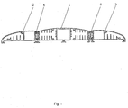
Fig. 1 illustrates the cross section of the lighting device casing, in which three LED modules are combined by the connecting pieces (different designs are used for illustration). The left module is closed by the end cover; -
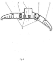
Fig. 2 illustrates the cross section of the lighting device, composed of three modules. The right and left connecting pieces are characterized by different designs; -
Fig. 3 illustrates the cross section of the third type of the lighting device, composed of five similar modules; -
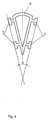
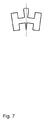
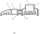
Fig. 4 ,Fig. 5 ,Fig. 6 andFig 7 illustrate scaled-up profile for different variants of the connecting pieces, with ventilating duct in that number, which may be used for connection of LED modules of the lighting device; -
Fig. 8 andFig 9 illustrate the disassembled connected modules. - The LED lighting device contains
modules 1, each equipped with the light source (not shown). The central supporting module is mounted on the supporting surface (not shown), which may be light tower, light post, building wall. Modules connection with each other is realized using connectingmember 2 designed withprojections 3, each being the first link of the sliding pair and thesecond link 4 of which is designed in the casing of the corresponding module. Theholes 5 are designed for drivers attachment. - The links composing the sliding pair in simple case are the T-shaped groove in the module's casing and
projection 3 of the corresponding profile on theconnecting piece 2. The dihedral angle A value of the connecting piece in this case is near zero. - In case of the inclined modules connection the wedge-shaped connecting piece 2 (
Figures 4 and7 ) is used, in which the dihedral angle A is selected with accounting of the desired relative position of the lighting device's emitting surfaces. - In order to connect the lighting device's modules the
projection 3 of the connectingmember 2 is directed to the groove in the casing and the forward movement of theprojection 3 in thegroove 4 along the casing is realized till the final positioning of the connecting piece. Similarly the next module of the device is connected to the connecting member. In case of necessity disassembling of the modules is realized in reverse order. - The connection process of the lighting device modules does not require the availability of any fastening elements and provides accuracy and reliability of their positioning. The fixing facility of the mutual position of links of the sliding pair is the end cover 6 (
Fig. 1 ), which is attached on the module casing. The lighting device assembling is simple and processable. Changing of the lighting device configuration or modules upgrading may be realized in the course of operation. At the same time creation of the common flat light-emitting surface, or the one turned outside, or directed to restricted area may be easily provided. - The designs presented in this description are not exhaustive. The design solutions bringing to equivalent result may be realized in different ways and may be adapted for realization of the present application. The design parts are characterized by such technological forms, which may be realized using the existing automated control facilities.
Claims (4)
- LED lighting device comprising at at least a two LED modules, each of which equipped with a light source and the housing of each module is the first link sliding translational pair characterized in that has at least one connecting member disposed between the housings LED modules, and acts as a second link translational pairs for each the housing of the LED modules, wherein the plane of the tangents to the point on the external surface of the connecting element form a dihedral the angle A whose magnitude is selected from mathematical expression:
 A - dihedral angle, plane of whose tangential to point on the external surface of the connecting element, the angular degree.
 - LED lighting device, characterized in that the connecting member has a length equal to the length housing.
- LED lighting device, characterized in that the connecting element is composed of two or more portions.
- LED lighting device, characterized in that the connecting element is made hollow
Applications Claiming Priority (2)
| Application Number | Priority Date | Filing Date | Title |
|---|---|---|---|
| RU2013125254/07A RU2528175C1 (en) | 2013-05-31 | 2013-05-31 | Light-emitting diode illumination device |
| PCT/RU2014/000325 WO2014193265A1 (en) | 2013-05-31 | 2014-05-06 | Led lighting device |
Publications (2)
| Publication Number | Publication Date |
|---|---|
| EP3006815A1 true EP3006815A1 (en) | 2016-04-13 |
| EP3006815A4 EP3006815A4 (en) | 2016-04-20 |
Family
ID=51540269
Family Applications (1)
| Application Number | Title | Priority Date | Filing Date |
|---|---|---|---|
| EP14804361.5A Withdrawn EP3006815A4 (en) | 2013-05-31 | 2014-05-06 | Led lighting device |
Country Status (5)
| Country | Link |
|---|---|
| EP (1) | EP3006815A4 (en) |
| CN (1) | CN105247272A (en) |
| EA (1) | EA201500625A1 (en) |
| RU (1) | RU2528175C1 (en) |
| WO (1) | WO2014193265A1 (en) |
Cited By (1)
| Publication number | Priority date | Publication date | Assignee | Title |
|---|---|---|---|---|
| EP3754249A4 (en) * | 2018-06-07 | 2021-11-03 | Suzhou Opple Lighting Co., Ltd. | LAMP AND LAMP ASSEMBLY |
Families Citing this family (3)
| Publication number | Priority date | Publication date | Assignee | Title |
|---|---|---|---|---|
| RU2625459C1 (en) * | 2016-02-02 | 2017-07-14 | Валерий Викторович Игнатьев | Led lighting device (versions) |
| RU173797U1 (en) * | 2017-03-02 | 2017-09-12 | Общество с ограниченной ответственностью Производственно-техническое предприятие "ЭнергоСтандарт" | LED lamp |
| RU2656610C1 (en) * | 2017-05-31 | 2018-06-06 | Общество С Ограниченной Ответственностью Инжиниринговая Компания "Велес" | Led lighting device |
Family Cites Families (20)
| Publication number | Priority date | Publication date | Assignee | Title |
|---|---|---|---|---|
| US20030223231A1 (en) | 2002-05-28 | 2003-12-04 | Mccarthy Charles A. | Selectively extendable modular lighting fixture, and method of making and assembly |
| DE50308782D1 (en) | 2002-12-24 | 2008-01-24 | Belux Ip Ag | Cascade-shaped, pluggable, electrical luminaire module with at least one fluorescent tube |
| CN101280896A (en) * | 2007-04-06 | 2008-10-08 | 深圳市阳光富源科技有限公司 | Novel wide-angle LED road lamp and manufacturing method thereof |
| CN101191596A (en) * | 2007-07-31 | 2008-06-04 | 宁波安迪光电科技有限公司 | High power LED road lamp and casing thereof |
| CN101469841B (en) * | 2007-12-28 | 2011-03-30 | 富士迈半导体精密工业(上海)有限公司 | lighting device |
| CN101498428B (en) * | 2008-01-28 | 2010-12-08 | 富士迈半导体精密工业(上海)有限公司 | lighting device |
| CN101539278B (en) * | 2008-03-19 | 2010-11-10 | 富准精密工业(深圳)有限公司 | LED combination |
| CN201218466Y (en) * | 2008-05-29 | 2009-04-08 | 傅小星 | High power LED lighting lamp |
| CN201344423Y (en) * | 2009-02-26 | 2009-11-11 | 复旦大学 | Street lamp adopting LEDs as light sources |
| IT1394901B1 (en) * | 2009-06-10 | 2012-07-20 | Spagnolo S R L | LAMP STRUCTURE. |
| CN101943334A (en) * | 2009-07-03 | 2011-01-12 | 富准精密工业(深圳)有限公司 | Lamp |
| CN101994916A (en) * | 2009-08-19 | 2011-03-30 | 李永臣 | Combinative light-emitting diode (LED) street lamp |
| CN201606720U (en) * | 2010-01-27 | 2010-10-13 | 周峰 | LED lamp with module irradiation angle multi-directional adjusting function |
| KR101027101B1 (en) | 2010-11-01 | 2011-04-05 | 박창수 | Lighting unit with improved heat dissipation structure and street lamp using the same |
| CN102563395B (en) * | 2010-12-23 | 2013-09-18 | 海洋王照明科技股份有限公司 | Combined lamp |
| CN102128427B (en) * | 2011-01-13 | 2013-08-28 | 深圳市佳比泰电子科技有限公司 | Connecting device capable of bidirectionally adjusting lighting angle of LED (Light-Emitting Diode) street lamp and operating method thereof |
| UA64404U (en) * | 2011-03-28 | 2011-11-10 | Владимир Александрович Сачура | Led lighting device |
| RU114124U1 (en) * | 2011-07-18 | 2012-03-10 | Николай Александрович Кузнецов | LED LAMP |
| RU112340U1 (en) * | 2011-08-11 | 2012-01-10 | Общество с ограниченной ответственностью "ДиС ПЛЮС" | MODULAR LIGHT |
| UA75752U (en) * | 2012-06-06 | 2012-12-10 |
-
2013
- 2013-05-31 RU RU2013125254/07A patent/RU2528175C1/en not_active IP Right Cessation
-
2014
- 2014-05-06 EA EA201500625A patent/EA201500625A1/en unknown
- 2014-05-06 EP EP14804361.5A patent/EP3006815A4/en not_active Withdrawn
- 2014-05-06 CN CN201480031327.3A patent/CN105247272A/en active Pending
- 2014-05-06 WO PCT/RU2014/000325 patent/WO2014193265A1/en not_active Ceased
Cited By (1)
| Publication number | Priority date | Publication date | Assignee | Title |
|---|---|---|---|---|
| EP3754249A4 (en) * | 2018-06-07 | 2021-11-03 | Suzhou Opple Lighting Co., Ltd. | LAMP AND LAMP ASSEMBLY |
Also Published As
| Publication number | Publication date |
|---|---|
| RU2528175C1 (en) | 2014-09-10 |
| EA201500625A1 (en) | 2015-09-30 |
| EP3006815A4 (en) | 2016-04-20 |
| WO2014193265A1 (en) | 2014-12-04 |
| CN105247272A (en) | 2016-01-13 |
Similar Documents
| Publication | Publication Date | Title |
|---|---|---|
| EP2396591B1 (en) | Led lighting fixture | |
| US20150308667A1 (en) | Wall Mount Light Assembly | |
| DE102008052869B4 (en) | Luminaire with LED mounting rail | |
| EP3151351A1 (en) | Improvements to sections of cable trays | |
| EP3956715A4 (en) | COMMERCIAL SYSTEM BASED ON A LIGHT FIELD DISPLAY SYSTEM | |
| JP2017529652A5 (en) | ||
| KR200487590Y1 (en) | Fire extinguisher locator | |
| US20160102839A1 (en) | Module high-bay lighting systems and methods of providing lighting | |
| US10823367B1 (en) | Modular LED light fixture with spaced diffuser | |
| CN105247272A (en) | LED lighting | |
| CN103056877A (en) | Mechanical arm | |
| EP3339718A2 (en) | Luminous flux creation method and extended cornice lamp for implementing same | |
| EP2938923B1 (en) | Warning lighting system using led beacon arrays with a single master power supply | |
| AT14622U1 (en) | Luminaire or lighting arrangement with an elongate carrier element and releasably attachable light module | |
| US20110154800A1 (en) | Chain link for an energy guiding chain | |
| EP3477805B1 (en) | Cable ladder corner | |
| US20190249851A1 (en) | Light tube | |
| US20230383519A1 (en) | Connecting hardware and structure system | |
| CN219606479U (en) | LED flexible screen with adjustable inner and outer radians | |
| CN104848172A (en) | Opto-mechanically adjustable and expandable light boards | |
| JP2016004754A (en) | LED lighting device | |
| EP3182000A1 (en) | Compact robotic locally adjustable lighting of workspace of medical facilities | |
| EP2740989A1 (en) | Lighting device | |
| EP3522315A1 (en) | Connection device for connecting two cable tray segments at a variable angle | |
| TW200728691A (en) | Transmissive optical encoder |
Legal Events
| Date | Code | Title | Description |
|---|---|---|---|
| PUAI | Public reference made under article 153(3) epc to a published international application that has entered the european phase |
Free format text: ORIGINAL CODE: 0009012 |
|
| 17P | Request for examination filed |
Effective date: 20150918 |
|
| AK | Designated contracting states |
Kind code of ref document: A1 Designated state(s): AL AT BE BG CH CY CZ DE DK EE ES FI FR GB GR HR HU IE IS IT LI LT LU LV MC MK MT NL NO PL PT RO RS SE SI SK SM TR |
|
| AX | Request for extension of the european patent |
Extension state: BA ME |
|
| A4 | Supplementary search report drawn up and despatched |
Effective date: 20160318 |
|
| RIC1 | Information provided on ipc code assigned before grant |
Ipc: F21V 21/30 20060101ALI20160314BHEP Ipc: F21V 19/00 20060101ALI20160314BHEP Ipc: F21S 2/00 20160101AFI20160314BHEP Ipc: F21Y 115/10 20160101ALN20160314BHEP |
|
| DAX | Request for extension of the european patent (deleted) | ||
| STAA | Information on the status of an ep patent application or granted ep patent |
Free format text: STATUS: THE APPLICATION IS DEEMED TO BE WITHDRAWN |
|
| 18D | Application deemed to be withdrawn |
Effective date: 20171201 |