EP3006722A1 - Driveshaft assembly - Google Patents
Driveshaft assembly Download PDFInfo
- Publication number
- EP3006722A1 EP3006722A1 EP15180772.4A EP15180772A EP3006722A1 EP 3006722 A1 EP3006722 A1 EP 3006722A1 EP 15180772 A EP15180772 A EP 15180772A EP 3006722 A1 EP3006722 A1 EP 3006722A1
- Authority
- EP
- European Patent Office
- Prior art keywords
- cam
- shaft
- plunger
- driveshaft assembly
- driveshaft
- Prior art date
- Legal status (The legal status is an assumption and is not a legal conclusion. Google has not performed a legal analysis and makes no representation as to the accuracy of the status listed.)
- Granted
Links
Images




Classifications
-
- F—MECHANICAL ENGINEERING; LIGHTING; HEATING; WEAPONS; BLASTING
- F02—COMBUSTION ENGINES; HOT-GAS OR COMBUSTION-PRODUCT ENGINE PLANTS
- F02M—SUPPLYING COMBUSTION ENGINES IN GENERAL WITH COMBUSTIBLE MIXTURES OR CONSTITUENTS THEREOF
- F02M59/00—Pumps specially adapted for fuel-injection and not provided for in groups F02M39/00 -F02M57/00, e.g. rotary cylinder-block type of pumps
- F02M59/02—Pumps specially adapted for fuel-injection and not provided for in groups F02M39/00 -F02M57/00, e.g. rotary cylinder-block type of pumps of reciprocating-piston or reciprocating-cylinder type
- F02M59/025—Pumps specially adapted for fuel-injection and not provided for in groups F02M39/00 -F02M57/00, e.g. rotary cylinder-block type of pumps of reciprocating-piston or reciprocating-cylinder type characterised by a single piston
- F02M59/027—Unit-pumps, i.e. single piston and cylinder pump-units, e.g. for cooperating with a camshaft
-
- F—MECHANICAL ENGINEERING; LIGHTING; HEATING; WEAPONS; BLASTING
- F02—COMBUSTION ENGINES; HOT-GAS OR COMBUSTION-PRODUCT ENGINE PLANTS
- F02M—SUPPLYING COMBUSTION ENGINES IN GENERAL WITH COMBUSTIBLE MIXTURES OR CONSTITUENTS THEREOF
- F02M65/00—Testing fuel-injection apparatus, e.g. testing injection timing ; Cleaning of fuel-injection apparatus
-
- F—MECHANICAL ENGINEERING; LIGHTING; HEATING; WEAPONS; BLASTING
- F02—COMBUSTION ENGINES; HOT-GAS OR COMBUSTION-PRODUCT ENGINE PLANTS
- F02M—SUPPLYING COMBUSTION ENGINES IN GENERAL WITH COMBUSTIBLE MIXTURES OR CONSTITUENTS THEREOF
- F02M57/00—Fuel-injectors combined or associated with other devices
- F02M57/02—Injectors structurally combined with fuel-injection pumps
- F02M57/022—Injectors structurally combined with fuel-injection pumps characterised by the pump drive
- F02M57/023—Injectors structurally combined with fuel-injection pumps characterised by the pump drive mechanical
-
- F—MECHANICAL ENGINEERING; LIGHTING; HEATING; WEAPONS; BLASTING
- F02—COMBUSTION ENGINES; HOT-GAS OR COMBUSTION-PRODUCT ENGINE PLANTS
- F02M—SUPPLYING COMBUSTION ENGINES IN GENERAL WITH COMBUSTIBLE MIXTURES OR CONSTITUENTS THEREOF
- F02M59/00—Pumps specially adapted for fuel-injection and not provided for in groups F02M39/00 -F02M57/00, e.g. rotary cylinder-block type of pumps
- F02M59/02—Pumps specially adapted for fuel-injection and not provided for in groups F02M39/00 -F02M57/00, e.g. rotary cylinder-block type of pumps of reciprocating-piston or reciprocating-cylinder type
- F02M59/10—Pumps specially adapted for fuel-injection and not provided for in groups F02M39/00 -F02M57/00, e.g. rotary cylinder-block type of pumps of reciprocating-piston or reciprocating-cylinder type characterised by the piston-drive
- F02M59/102—Mechanical drive, e.g. tappets or cams
-
- F—MECHANICAL ENGINEERING; LIGHTING; HEATING; WEAPONS; BLASTING
- F02—COMBUSTION ENGINES; HOT-GAS OR COMBUSTION-PRODUCT ENGINE PLANTS
- F02M—SUPPLYING COMBUSTION ENGINES IN GENERAL WITH COMBUSTIBLE MIXTURES OR CONSTITUENTS THEREOF
- F02M59/00—Pumps specially adapted for fuel-injection and not provided for in groups F02M39/00 -F02M57/00, e.g. rotary cylinder-block type of pumps
- F02M59/20—Varying fuel delivery in quantity or timing
- F02M59/30—Varying fuel delivery in quantity or timing with variable-length-stroke pistons
-
- F—MECHANICAL ENGINEERING; LIGHTING; HEATING; WEAPONS; BLASTING
- F02—COMBUSTION ENGINES; HOT-GAS OR COMBUSTION-PRODUCT ENGINE PLANTS
- F02M—SUPPLYING COMBUSTION ENGINES IN GENERAL WITH COMBUSTIBLE MIXTURES OR CONSTITUENTS THEREOF
- F02M59/00—Pumps specially adapted for fuel-injection and not provided for in groups F02M39/00 -F02M57/00, e.g. rotary cylinder-block type of pumps
- F02M59/44—Details, components parts, or accessories not provided for in, or of interest apart from, the apparatus of groups F02M59/02 - F02M59/42; Pumps having transducers, e.g. to measure displacement of pump rack or piston
- F02M59/48—Assembling; Disassembling; Replacing
-
- F—MECHANICAL ENGINEERING; LIGHTING; HEATING; WEAPONS; BLASTING
- F02—COMBUSTION ENGINES; HOT-GAS OR COMBUSTION-PRODUCT ENGINE PLANTS
- F02M—SUPPLYING COMBUSTION ENGINES IN GENERAL WITH COMBUSTIBLE MIXTURES OR CONSTITUENTS THEREOF
- F02M2200/00—Details of fuel-injection apparatus, not otherwise provided for
- F02M2200/80—Fuel injection apparatus manufacture, repair or assembly
- F02M2200/8015—Provisions for assembly of fuel injection apparatus in a certain orientation, e.g. markings, notches or specially shaped sleeves other than a clip
Definitions
- the present invention relates to a driveshaft assembly, and more specifically to a cam and shaft for a driveshaft assembly.
- the cam 2 operates on a plunger 90, either directly (as illustrated in the Figures 1a and 1b ), or indirectly via a pivoting rocker arm (not shown). Lift is transferred to the plunger 90 or rocker arm in the direction of arrow L, via a lift point 6 on the outer surface 4 of the cam 2, where the outer surface 4 of the cam contacts with the plunger 90 (or rocker arm). In the orientation of Figures 1a and 1b , point 6 is the uppermost point of the outer surface 4 cam 2.
- the cam 2 rotates about a centre of rotation, defined by a longitudinal central axis 14 of the shaft 12, which is coincident with a central axis 70 of the base cylinder section 8.
- the contact point between the cam 2 and the plunger 90 moves around the outer surface 4 of the cam, i.e. lift point 6 moves relatively around the outer surface 4 of the cam 2.
- distance A will vary in accordance with the external profile 4b of the further section 10.
- distance A will be constant and will be equal to distance B.
- Figure 1a illustrates a rotational position of the cam 2 which provides maximum lift, Lmax, i.e. lift point 6 is at a maximum distance from the centre 14 of the shaft 12, and distance A is therefore maximised.
- Figure 1b illustrates a rotational position of the cam 2 providing minimum lift, i.e. lift point 6 is at a minimum distance from the centre 14 of the shaft 12, and distance A is therefore minimised. In this position, A and B are equal, therefore the minimum lift Lmin is zero.
- the prior art embodiment of Figures 1a and 1b also provides a constant plunger rate period.
- a known disadvantage of the prior art embodiment such as that illustrated in Figures 1a and 1b is that the maximum lift Lmax of the driveshaft assembly 1, and therefore the travel of the plunger 90, is predetermined and fixed, as each driveshaft assembly has a set value of B and set maximum value of A.
- To obtain a different value for the travel of the plunger 90 it is necessary to disassemble the driveshaft assembly 1 by removing the cam 2 from the shaft 12, and replacing it with an alternative cam having a different external profile, i.e. a different value of B and/or maximum A, and/or by replacing the rocker arm or changing the pivot point of the rocker arm.
- the present invention comprises, in a first aspect, a driveshaft assembly in accordance with claim 1.
- the present invention enables different values of maximum lift to be achieved using a single cam and shaft combination, i.e. a variable plunger lift is enabled for a single cam and shaft combination. Accordingly, a required value of maximum lift can be selected by use of the same cam and shaft, avoiding the need to use a multiple cam and/or rocker arm combinations to achieve different values of maximum lift.
- the offset value may vary between zero and a maximum offset value.
- the indexing means may comprises splines.
- the splines comprise a first annular set of splines provided on an internal surface of the through bore of the cam, which correspond with a second annular set of splines provided on a section of the shaft, wherein a centre of a circumference of the splines is offset from the central axis of the shaft, and wherein the cam is a push fit onto the shaft, and wherein the plurality of rotational positions comprise a plurality of discreet rotational positions.
- the driveshaft assembly may further comprise a position indicator, to indicate a relative position at which the cam has been assembled onto the shaft.
- the present invention comprises a driveshaft and plunger assembly, comprising a driveshaft assembly in accordance with the first aspect of the present invention, and a plunger arranged for reciprocating movement caused by lift imparted by the cam during rotation of the shaft.
- the driveshaft and plunger assembly may further comprise a rocker arm, wherein lift is imparted to the plunger by the cam to the plunger via the rocker arm.
- the present invention comprises a machine for testing a fuel injectors or pump, such as an UI, EUI or EUP, comprising a driveshaft assembly in accordance with the first aspect of the present invention, wherein the driveshaft assembly causes reciprocating movement of a plunger of the fuel injector or pump.
- the present invention provides a simpler and cheaper solution than prior art driveshaft assemblies.
- the present invention comprises a driveshaft assembly 100 comprising a cam 102 and a shaft 112.
- the cam 102 comprises a base cylinder section 108, having a longitudinal central axis 170, and an integral further section 110, protruding from part of the circumference of the base cylinder section 108.
- An outer surface 104 of the cam 102 is defined by an outer surface 104a of the base cylinder section 108, and an outer surface 104b of the further section 110.
- the driveshaft assembly 100 is arranged to act upon a reciprocating component comprising a plunger 190 (shown in Figures 3a, 3b , 5a, 5b , 7a and 7b ).
- a longitudinally extending bore 116 is provided through the base cylinder section 108.
- the bore 116 is provided with a first set of splines, comprising a plurality of internal splines 118 defined by a plurality of troughs and peaks.
- An annular section 150 of the shaft 112 is provided a second set of splines, comprising a plurality of external splines 152, defined by a plurality of peaks and troughs.
- the annular section 150 is eccentric with the shaft 112, i.e. the central axis of the splines 152 is offset from a central axis 114 of the shaft 112.
- the cam 102 On assembly of the driveshaft assembly 100, the cam 102 is pushed onto the shaft 112, until the splines 118 of the cam 102 are located over the external splines 152 of the shaft 112.
- the external splines 152 of the shaft 112 cooperate with the internal splines 118 provided on the cam bore 116, such that the cam 102 is a push fit onto shaft 112.
- An annular section 180 of the shaft 112 (shown on Figure 2 ), which is of greater diameter that of the bore 116 of the cam 102, provides a stop, ensuring that the cam 102 and shaft 112 are located correctly with one another after the cam 102 has been pushed onto the shaft 112.
- the indexing means is annular and cylindrical. Due to the eccentricity of the annular section 150 with the shaft 112, a central axis 154 of the splined section 162 of the assembled driveshaft assembly 100 is offset from the central axis 114 of the shaft 112, by a distance C, as indicated in the Figures. In other words, a circumference of the indexing means is eccentric with the shaft 112.
- the indexing means allow the cam 102 to be located on the shaft 112 at a number of discreet positions, each of which provides a different maximum value of lift, Lmax. (The calculation and variation of Lmax is described in greater detail below).
- the central axis 154 of the splined section 162 is offset from the central axis 114 of the shaft 112, by distance C, in all arrangements of the cam 102 and shaft 112, i.e. at all indexed positions.
- the central axis 170 of the base cylinder section 108 from the central axis 114 of the shaft 112 can be varied between zero and D (D is illustrated in Figures 5a and 7a ), in either or both of the X and Y axes (indicated in the Figures).
- Each discreet position at which the cam 102 can be located on the shaft 112 provides a different offset value D, which determines the maximum value of lift, Lmax.
- a position indicator 156 (shown in Figures 3a, 3b , 5a, 5b , 7a and 7b ), is provided to indicate the relative position of the cam 102 on the shaft 112.
- eleven positions of the cam 102 relative to the shaft 112 are indicated by numerals 1 to 11; each of these positions provides a known value of Lmax and therefore a known value of travel of the plunger 190.
- distance A will vary in accordance with the rotational orientation of the cam 102 with respect to the centre 114 of the shaft 112.
- the lift, L, of the driveshaft assembly 100 varies between a maximum value, Lmax, and a minimum value of zero. As illustrated in Figures 3a , 5a and 7a , Lmax occurs when distance A is maximised and distance B is minimised. The minimum, zero value of lift occurs when distance A is equal to distance B, as illustrated in Figures 3b , 5b and 7b .
- a maximum value of A is equal to the maximum distance between the central axis 114 of the shaft 112 and the outer surface 4b of the further section 110 of the cam 102.
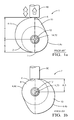
- Figure 3a illustrates the driveshaft assembly 100 at the maximum lift position, i.e. wherein the value of distance A is maximised.
- Figure 3b illustrates the driveshaft assembly 100 further around the rotational cycle, wherein distance A is at a minimum and is equal to distance B thereby providing an instantaneous lift value L of zero.
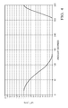
- Figure 4 provides an example of a lift profile during rotation, of the driveshaft assembly 100 when the cam 102 is located on the shaft in position 11, and wherein the offset C, (of the central axis 154 of the splined section 162 and the central axis 114 of the shaft 112), is 1.5mm. (The maximum value of offset D for this arrangement is also 1.5mm).
- the lift L varies between zero and an Lmax value of 12mm.
- the central axis 170 of the base cylinder section 108 is offset from the central axis 114 of the shaft 112, by distance D, in the X axis.
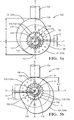
- Figure 5b illustrates the driveshaft assembly 100 in position 1, further around the cycle, when distance A is equal to distance B, and instantaneous lift L is therefore zero.
- Figure 6 corresponds to Figure 4 , and illustrates the lift profile of the same embodiment of driveshaft assembly 100 when the cam 102 has been assembled onto the shaft 112 in position 1.
- the maximum value of lift, Lmax is now 18mm, an increase of 6mm relative to the arrangement of Figures 3a and 3b .
- Figure 8 corresponds to Figures 4 and 6 , and illustrates the lift profile of the same embodiment of driveshaft assembly 100, when the cam 102 has been assembled onto the shaft 112 in position 6.
- the maximum value of lift Lmax is now 15.5mm, i.e. between the Lmax values of Figures 4 and 6 .
- the cam 102 acts directly on the plunger 190.
- the cam 102 could act indirectly on the plunger 190, via a rocker arm.
- the present invention can replace any driveshaft embodiment.
- a testing machine for a fuel injector or pump such as an UI, EUI or EUP.
- An example of a machine 200 for testing an injector 300 is illustrated Figure 9 , and comprises a driveshaft assembly 101 in accordance with the present invention.
- the cam 102 is housed in a cambox 210 comprising a cambox cover 208.
- the cambox 210 is mounted on a bedplate adapter 211 via an adapter plate 209.
- the machine 200 further comprises a pressure plate 213 and injector support plate 212 into which the injector 300 is clamped and held in position by a locknut 203.
- a rotary drive is connected to the camshaft 112 and rotates the shaft 112 and cam 102, for example at speeds of 30 to 4000rpm, which causes a cam follower 205 and hence a pressurising plunger (not shown) of the injector 300 to move in a reciprocating motion.
- the plunger generates an increasing fuel pressure within the injector 300 when an electronically operated spill valve (not shown) is closed.
- a nozzle (not shown) of the injector 300 is caused to open when fuel pressure within the injector 300 reaches a predetermined threshold.
- the machine 200 measures parameters of the injector 300 such as injected fuel quantity.
- the machine 200 may be used to test different types of injector or pump which have plungers requiring different values of maximum lift Lmax.
- the driveshaft assembly 101 of the present invention enables the machine to test different injector/pump types having different Lmax requirements, without requiring the fitting of different cams / cam follower combinations to the machine.
- the indexing means comprises cooperating splines provided on the shaft and on the bore of the cam.
- alternative indexing means could be used.
- alternative embodiments could enable a different number of discreet indexed positions, and therefore a different number of possible values of Lmax.
- a different number of splines would enable a different number of discreet positional arrangements of the cam onto the shaft.
Landscapes
- Engineering & Computer Science (AREA)
- Chemical & Material Sciences (AREA)
- Combustion & Propulsion (AREA)
- Mechanical Engineering (AREA)
- General Engineering & Computer Science (AREA)
- Reciprocating Pumps (AREA)
- Shafts, Cranks, Connecting Bars, And Related Bearings (AREA)
- Fuel-Injection Apparatus (AREA)
- Transmission Devices (AREA)
- Gears, Cams (AREA)
Abstract
Description
- The present invention relates to a driveshaft assembly, and more specifically to a cam and shaft for a driveshaft assembly.
- Fuel pumping and pressurising plungers of Electronic Unit Injectors (EUI), Unit Injectors (UI) and Electronic Unit Pumps (EUP), are operated in a reciprocating manner. In a known driveshaft arrangement or
assembly 1, as illustrated inFigures 1a and 1b , reciprocating motion of aplunger 90, as indicated by arrow P, is caused by a rotatingcam 2 located on ashaft 12. Thecam 2 is formed of abase cylinder section 8, and an integralfurther section 10, protruding from part of the circumference of thebase cylinder section 8. Thecam 2 therefore has anouter surface 4 defined partly by the outer surface 4a of thebase cylinder 8, and partly by the outer surface 4b of thefurther section 10. - The
cam 2 operates on aplunger 90, either directly (as illustrated in theFigures 1a and 1b ), or indirectly via a pivoting rocker arm (not shown). Lift is transferred to theplunger 90 or rocker arm in the direction of arrow L, via alift point 6 on theouter surface 4 of thecam 2, where theouter surface 4 of the cam contacts with the plunger 90 (or rocker arm). In the orientation ofFigures 1a and 1b ,point 6 is the uppermost point of theouter surface 4cam 2. - The
cam 2 rotates about a centre of rotation, defined by a longitudinalcentral axis 14 of theshaft 12, which is coincident with a central axis 70 of thebase cylinder section 8. As thecam 2 rotates with theshaft 12, the contact point between thecam 2 and theplunger 90, moves around theouter surface 4 of the cam, i.e.lift point 6 moves relatively around theouter surface 4 of thecam 2. - As illustrated in
Figures 1a and 1b , the instantaneous lift L of thecam 2 is calculated as below:
L = A - B;
where A is the distance from acentral axis 14 of theshaft 12 to thelift point 6, and B is the distance from thecentral axis 14 of theshaft 12 to the external surface 4a of thebase cylinder section 8, i.e. a radius of thebase cylinder section 8. - During part of the rotation cycle, when the
lift point 6 occurs on the external surface 4b of thefurther section 10, the distance A will vary in accordance with the external profile 4b of thefurther section 10. During the part of the rotation cycle when thelift point 6 occurs on the external surface 4a of thebase cylinder section 8, distance A will be constant and will be equal to distance B. -
Figure 1a illustrates a rotational position of thecam 2 which provides maximum lift, Lmax,i.e. lift point 6 is at a maximum distance from thecentre 14 of theshaft 12, and distance A is therefore maximised. -
Figure 1b illustrates a rotational position of thecam 2 providing minimum lift,i.e. lift point 6 is at a minimum distance from thecentre 14 of theshaft 12, and distance A is therefore minimised. In this position, A and B are equal, therefore the minimum lift Lmin is zero. - Typically, the prior art embodiment of
Figures 1a and 1b also provides a constant plunger rate period. A known disadvantage of the prior art embodiment such as that illustrated inFigures 1a and 1b is that the maximum lift Lmax of thedriveshaft assembly 1, and therefore the travel of theplunger 90, is predetermined and fixed, as each driveshaft assembly has a set value of B and set maximum value of A. To obtain a different value for the travel of theplunger 90, it is necessary to disassemble thedriveshaft assembly 1 by removing thecam 2 from theshaft 12, and replacing it with an alternative cam having a different external profile, i.e. a different value of B and/or maximum A, and/or by replacing the rocker arm or changing the pivot point of the rocker arm. - Accordingly, in prior art embodiments, it is difficult to accommodate the differing plunger travel requirements. For example, it is difficult to accommodate the specific lift range requirements of different EUI, UI and EUP families, which could typically range from 9mm to 19mm.
- It is an object of the present invention to provide an improved driveshaft assembly which at least mitigates the above mentioned problems.
- Accordingly the present invention comprises, in a first aspect, a driveshaft assembly in accordance with
claim 1. - The present invention enables different values of maximum lift to be achieved using a single cam and shaft combination, i.e. a variable plunger lift is enabled for a single cam and shaft combination. Accordingly, a required value of maximum lift can be selected by use of the same cam and shaft, avoiding the need to use a multiple cam and/or rocker arm combinations to achieve different values of maximum lift.
- The offset value may vary between zero and a maximum offset value.
- The indexing means may comprises splines. In one embodiment, the splines comprise a first annular set of splines provided on an internal surface of the through bore of the cam, which correspond with a second annular set of splines provided on a section of the shaft, wherein a centre of a circumference of the splines is offset from the central axis of the shaft, and wherein the cam is a push fit onto the shaft, and wherein the plurality of rotational positions comprise a plurality of discreet rotational positions.
- The driveshaft assembly may further comprise a position indicator, to indicate a relative position at which the cam has been assembled onto the shaft.
- In a further aspect, the present invention comprises a driveshaft and plunger assembly, comprising a driveshaft assembly in accordance with the first aspect of the present invention, and a plunger arranged for reciprocating movement caused by lift imparted by the cam during rotation of the shaft.
- The driveshaft and plunger assembly may further comprise a rocker arm, wherein lift is imparted to the plunger by the cam to the plunger via the rocker arm.
- In a further aspect, the present invention comprises a machine for testing a fuel injectors or pump, such as an UI, EUI or EUP, comprising a driveshaft assembly in accordance with the first aspect of the present invention, wherein the driveshaft assembly causes reciprocating movement of a plunger of the fuel injector or pump.
- The present invention provides a simpler and cheaper solution than prior art driveshaft assemblies.
- The present invention is now described by way of example with reference to the accompanying drawings in which:
-
Figure 2 is an exploded view of a driveshaft assembly in accordance with the present invention; -
Figures 3a and 3b are end views of the driveshaft assembly ofFigure 2 wherein the cam is located on the shaft in a first, a minimum Lmax lift position; -
Figure 4 is a graphical representation of a lift profile of the driveshaft assembly at the minimum lift position ofFigures 3a and 3b ; -
Figures 5a and 5b are end views of the driveshaft assembly ofFigure 2 , in which the cam is located on the shaft in a second, maximum Lmax lift position; -
Figures 6 is a graphical representation of a lift profile of the driveshaft assembly at the maximum lift position ofFigures 5a and 5b ; -
Figures 7a and 7b are end views of the driveshaft assembly ofFigure 2 , in which the cam is positioned on the shaft at a third, mid-Lmax position; -
Figure 8 is a graphical representation of a lift profile of the driveshaft assembly at the mid-Lmax position ofFigures 7a and 7b ;
and -
Figure 9 is an isometric view of a testing machine in accordance with the present invention. - Referring initially to
Figure 2 , the present invention comprises adriveshaft assembly 100 comprising acam 102 and ashaft 112. Thecam 102 comprises abase cylinder section 108, having a longitudinalcentral axis 170, and an integralfurther section 110, protruding from part of the circumference of thebase cylinder section 108. An outer surface 104 of thecam 102 is defined by an outer surface 104a of thebase cylinder section 108, and an outer surface 104b of thefurther section 110. - In the illustrated embodiment, the
driveshaft assembly 100 is arranged to act upon a reciprocating component comprising a plunger 190 (shown inFigures 3a, 3b ,5a, 5b ,7a and 7b ). - A longitudinally extending
bore 116 is provided through thebase cylinder section 108. - The
bore 116 is provided with a first set of splines, comprising a plurality ofinternal splines 118 defined by a plurality of troughs and peaks. - An
annular section 150 of theshaft 112 is provided a second set of splines, comprising a plurality ofexternal splines 152, defined by a plurality of peaks and troughs. Theannular section 150 is eccentric with theshaft 112, i.e. the central axis of thesplines 152 is offset from acentral axis 114 of theshaft 112. - On assembly of the
driveshaft assembly 100, thecam 102 is pushed onto theshaft 112, until thesplines 118 of thecam 102 are located over theexternal splines 152 of theshaft 112. - The
external splines 152 of theshaft 112 cooperate with theinternal splines 118 provided on thecam bore 116, such that thecam 102 is a push fit ontoshaft 112. - An
annular section 180 of the shaft 112 (shown onFigure 2 ), which is of greater diameter that of thebore 116 of thecam 102, provides a stop, ensuring that thecam 102 andshaft 112 are located correctly with one another after thecam 102 has been pushed onto theshaft 112. - On operation of the driveshaft, rotation of the
shaft 112 causes rotation of thecam 102, which acts upon the plunger 190 (Figures 3a, 3b ,5a, 5b ,7a and 7b ) at alift point 106, thereby imparting lift to theplunger 190 and causing theplunger 190 to move in a reciprocating movement, in the directions of arrow P (shown onFigure 3a ). - The
splines 118 of thecam 102, together with thesplines 152 of theshaft 112, form asplined section 162, which forms an indexing means. In this embodiment illustrated in the Figures, the indexing means is annular and cylindrical. Due to the eccentricity of theannular section 150 with theshaft 112, acentral axis 154 of thesplined section 162 of the assembleddriveshaft assembly 100 is offset from thecentral axis 114 of theshaft 112, by a distance C, as indicated in the Figures. In other words, a circumference of the indexing means is eccentric with theshaft 112. - The indexing means allow the
cam 102 to be located on theshaft 112 at a number of discreet positions, each of which provides a different maximum value of lift, Lmax. (The calculation and variation of Lmax is described in greater detail below). - Three central axes are defined above (as illustrated in
Figures 3, 3b ,5a, 5b ,7a and 7b ): - a
central axis 170 of thebase cylinder section 108; - a
central axis 114 of theshaft 112; - a
central axis 154 of thesplined section 162. - As above, the
central axis 154 of thesplined section 162 is offset from thecentral axis 114 of theshaft 112, by distance C, in all arrangements of thecam 102 andshaft 112, i.e. at all indexed positions. However, thecentral axis 170 of thebase cylinder section 108 from thecentral axis 114 of theshaft 112 can be varied between zero and D (D is illustrated inFigures 5a and7a ), in either or both of the X and Y axes (indicated in the Figures). - Each discreet position at which the
cam 102 can be located on theshaft 112 provides a different offset value D, which determines the maximum value of lift, Lmax. - A position indicator 156 (shown in
Figures 3a, 3b ,5a, 5b ,7a and 7b ), is provided to indicate the relative position of thecam 102 on theshaft 112. In the illustrated embodiment, eleven positions of thecam 102 relative to theshaft 112 are indicated bynumerals 1 to 11; each of these positions provides a known value of Lmax and therefore a known value of travel of theplunger 190. - As illustrated in
Figures 3a, 3b ,5a, 5b ,7a and 7b , the instantaneous lift L of thecam 102 is calculated as below:
central axis 114 of theshaft 112 to thelift point 106, and B is the distance from thecentral axis 114 of theshaft 112 to the external surface 104a of thebase cylinder section 108. - As the
cam 102 rotates and thelift point 106 moves around the outer surface 104 of thecam 102, due to the external profile of the outer surface 104 of thecam 102, distance A will vary in accordance with the rotational orientation of thecam 102 with respect to thecentre 114 of theshaft 112. - The lift, L, of the
driveshaft assembly 100 varies between a maximum value, Lmax, and a minimum value of zero. As illustrated inFigures 3a ,5a and7a , Lmax occurs when distance A is maximised and distance B is minimised. The minimum, zero value of lift occurs when distance A is equal to distance B, as illustrated inFigures 3b ,5b and7b . - A maximum value of A is equal to the maximum distance between the
central axis 114 of theshaft 112 and the outer surface 4b of thefurther section 110 of thecam 102. - The
cam 102 assembled onto theshaft 112 at three of the eleven positions will be described below in greater detail. - In
Figures 3a and 3b , thecam 102 has been assembled onto theshaft 112 atposition 11, providing a minimum value of Lmax, and therefore a minimum value of travel of theplunger 190. - In this position, the offset D of the
central axis 170 of thebase cylinder section 108, from thecentral axis 114 of theshaft 112, is zero, i.e. thecentral axes -
Figure 3a illustrates thedriveshaft assembly 100 at the maximum lift position, i.e. wherein the value of distance A is maximised.Figure 3b illustrates thedriveshaft assembly 100 further around the rotational cycle, wherein distance A is at a minimum and is equal to distance B thereby providing an instantaneous lift value L of zero. -
Figure 4 provides an example of a lift profile during rotation, of thedriveshaft assembly 100 when thecam 102 is located on the shaft inposition 11, and wherein the offset C, (of thecentral axis 154 of thesplined section 162 and thecentral axis 114 of the shaft 112), is 1.5mm. (The maximum value of offset D for this arrangement is also 1.5mm). The lift L varies between zero and an Lmax value of 12mm. - In
Figures 5a and 5b , thecam 102 has been assembled onto theshaft 112 inposition 1, wherein thecam 102 has been rotated 180□ with respect to the position ofFigures 3a and 3b . In this position, thedriveshaft assembly 100 provides a maximum value of Lmax, and therefore a maximum travel of a plunger. - In the arrangement of
Figures 5a and 5b , thecentral axis 170 of thebase cylinder section 108 is offset from thecentral axis 114 of theshaft 112, by distance D, in the X axis. - Relative to the arrangement of
Figures 3a and 3b , the maximum value of distance A (which occurs at the rotational position illustrated inFigure 5a ), has increased by both the offset values C and D, and maximum value of distance B, has decreased by both the offset values C and D. Accordingly, Lmax, which occurs at the rotational position ofFigure 5a , is maximised. -
Figure 5b illustrates thedriveshaft assembly 100 inposition 1, further around the cycle, when distance A is equal to distance B, and instantaneous lift L is therefore zero. -
Figure 6 corresponds toFigure 4 , and illustrates the lift profile of the same embodiment ofdriveshaft assembly 100 when thecam 102 has been assembled onto theshaft 112 inposition 1. As illustrated, the maximum value of lift, Lmax, is now 18mm, an increase of 6mm relative to the arrangement ofFigures 3a and 3b . - In
Figures 7a and 7b , thecam 102 has been assembled onto theshaft 112 inposition 6, wherein thecam 102 has been rotated 90□ with respect to the position ofFigures 3a and 3b . In this position, thedriveshaft assembly 100 provides a mid-value of Lmax and therefore a mid-value of travel of theplunger 190. - In the position of
Figures 7a and 7b , thecentral axis 170 of thebase cylinder portion 108 is offset by distance D from the centre ofrotation 114 of theshaft 112, in both the X and Y axes. -
Figure 8 corresponds toFigures 4 and6 , and illustrates the lift profile of the same embodiment ofdriveshaft assembly 100, when thecam 102 has been assembled onto theshaft 112 inposition 6. As illustrated, the maximum value of lift Lmax is now 15.5mm, i.e. between the Lmax values ofFigures 4 and6 . - Examples of the values of A, B and L for a
driveshaft 100 in accordance with the present invention, in the three positions described above, are provided in the table below, wherein the offsets C and D are each 1.5mm. The values of L are instantaneous values at the rotational position illustrated in each Figure.A (mm) B (mm) L (mm) Figure 3a 42 30 12 (Lmax) Figure 3b 30 30 0 Figure 5a 45 27 18 (Lmax) Figure 5b 27 27 0 Figure 7a 43.5 28.5 15 (Lmax) Figure 7b 28.5 28.5 0 - In the embodiments described above, the
cam 102 acts directly on theplunger 190. Alternatively, thecam 102 could act indirectly on theplunger 190, via a rocker arm. - The present invention can replace any driveshaft embodiment. One particular use could be for a testing machine for a fuel injector or pump such as an UI, EUI or EUP. An example of a
machine 200 for testing aninjector 300 is illustratedFigure 9 , and comprises adriveshaft assembly 101 in accordance with the present invention. Thecam 102 is housed in acambox 210 comprising acambox cover 208. Thecambox 210 is mounted on abedplate adapter 211 via anadapter plate 209. - The
machine 200 further comprises apressure plate 213 andinjector support plate 212 into which theinjector 300 is clamped and held in position by alocknut 203. A rotary drive is connected to thecamshaft 112 and rotates theshaft 112 andcam 102, for example at speeds of 30 to 4000rpm, which causes acam follower 205 and hence a pressurising plunger (not shown) of theinjector 300 to move in a reciprocating motion. The plunger generates an increasing fuel pressure within theinjector 300 when an electronically operated spill valve (not shown) is closed. A nozzle (not shown) of theinjector 300 is caused to open when fuel pressure within theinjector 300 reaches a predetermined threshold. - During operation, the
machine 200 measures parameters of theinjector 300 such as injected fuel quantity. - The
machine 200 may be used to test different types of injector or pump which have plungers requiring different values of maximum lift Lmax. Thedriveshaft assembly 101 of the present invention enables the machine to test different injector/pump types having different Lmax requirements, without requiring the fitting of different cams / cam follower combinations to the machine. - In the above embodiments, the indexing means comprises cooperating splines provided on the shaft and on the bore of the cam. In alternative embodiments of the present invention, alternative indexing means could be used.
- Furthermore, alternative embodiments could enable a different number of discreet indexed positions, and therefore a different number of possible values of Lmax. For example, a different number of splines would enable a different number of discreet positional arrangements of the cam onto the shaft.
-
-
driveshaft assembly 100 -
cam 102 - cam outer surface 104
- base cylinder section outer surface 104a
- further section outer surface 104b
- lift
point 106 -
base cylinder section 108 - cam
further section 110 -
shaft 112 - shaft
central axis 114 - bore 116
-
internal splines 118 - shaft
annular section 150 -
external splines 152 - splined section
central axis 154 -
position indicator 156 -
splined section 162 - base cylinder longitudinal
central axis 170 - increased diameter shaft
annular section 180 -
plunger 190 - offset C
- maximum value of lift Lmax
- plunger movement P
- variation of base cylinder central axis D
- axes X, Y
- offset Y
- cam shaft relative positions 1 - 11
- distance central axis of shaft to lift point A
- distance central axis of shaft to external surface base cylinder section B
-
machine 200 -
locknut 203 -
cam follower 205 -
cambox cover 208 -
adapter plate 209 -
cambox 210 -
bedplate adapter 211 -
pressure plate 213 -
injector support plate 212 -
injector 300
Claims (8)
- A driveshaft assembly for imparting lift to a plunger, the arrangement comprising a cam and a shaft;
the cam comprising a base cylinder section and an integral further section, wherein an outer profile of the cam is defined partly by an outer surface of the base cylinder section and partly by an outer surface of the further section;
wherein the shaft is insertable through a through bore provided in the base cylinder section of the cam thereby to form the driveshaft assembly;
wherein the driveshaft assembly further comprises an indexing means, which enable the cam to be assembled onto the shaft at a plurality of rotational positions, wherein at each rotational position, a central axis of the base cylinder section is offset from a central axis of the shaft by a different offset value. - A driveshaft assembly as claimed in claim 1 wherein the offset value varies between zero and a maximum offset value.
- A driveshaft assembly as claimed in claim 1 or claim 2 wherein the indexing means comprises splines.
- A driveshaft assembly as claimed in claim 3 wherein the splines comprise a first annular set of splines provided on an internal surface of the through bore of the cam, which correspond with a second annular set of splines provided on a section of the shaft,
wherein a centre of a circumference of the splines is offset from the central axis of the shaft,
and wherein the cam is a push fit onto the shaft, and wherein the plurality of rotational positions comprise a plurality of discreet rotational positions. - A driveshaft assembly as claimed in any one of the preceding claims further comprising a position indicator, to indicate a relative position at which the cam has been assembled onto the shaft.
- A driveshaft and plunger assembly comprising a driveshaft assembly as claimed in any one of the preceding claims, and a plunger arranged for reciprocating movement caused by lift imparted by the cam during rotation of the shaft.
- A driveshaft and plunger assembly as claimed in claim 6 further comprising a rocker arm, wherein lift is imparted to the plunger by the cam to the plunger via the rocker arm.
- A machine for testing a fuel injector or pump, comprising a driveshaft assembly as claimed in any one of claims 1 to 5, wherein the driveshaft assembly causes reciprocating movement of a plunger of the fuel injector or pump.
Applications Claiming Priority (1)
| Application Number | Priority Date | Filing Date | Title |
|---|---|---|---|
| GBGB1415964.4A GB201415964D0 (en) | 2014-09-10 | 2014-09-10 | Driveshaft assembly |
Publications (2)
| Publication Number | Publication Date |
|---|---|
| EP3006722A1 true EP3006722A1 (en) | 2016-04-13 |
| EP3006722B1 EP3006722B1 (en) | 2017-10-11 |
Family
ID=51796446
Family Applications (1)
| Application Number | Title | Priority Date | Filing Date |
|---|---|---|---|
| EP15180772.4A Active EP3006722B1 (en) | 2014-09-10 | 2015-08-12 | Driveshaft assembly |
Country Status (7)
| Country | Link |
|---|---|
| US (1) | US10557448B2 (en) |
| EP (1) | EP3006722B1 (en) |
| JP (1) | JP2017534809A (en) |
| CN (1) | CN107076083B (en) |
| ES (1) | ES2646992T3 (en) |
| GB (1) | GB201415964D0 (en) |
| WO (1) | WO2016037790A1 (en) |
Cited By (1)
| Publication number | Priority date | Publication date | Assignee | Title |
|---|---|---|---|---|
| GB2574847A (en) * | 2018-06-20 | 2019-12-25 | Delphi Tech Ip Ltd | Camshaft |
Families Citing this family (1)
| Publication number | Priority date | Publication date | Assignee | Title |
|---|---|---|---|---|
| CN111828217B (en) * | 2019-04-19 | 2025-02-28 | 罗伯特·博世有限公司 | Pumps with variable cam profiles |
Citations (2)
| Publication number | Priority date | Publication date | Assignee | Title |
|---|---|---|---|---|
| GB2121908A (en) * | 1982-06-17 | 1984-01-04 | Nippon Piston Ring Co Ltd | A camshaft |
| WO2013035137A1 (en) * | 2011-09-09 | 2013-03-14 | Aichi Machine Industry Co., Ltd. | Fuel pump driving structure and internal combustion engine |
Family Cites Families (13)
| Publication number | Priority date | Publication date | Assignee | Title |
|---|---|---|---|---|
| GB191516182A (en) | 1915-11-17 | 1916-07-27 | Frank Hall | Improvements in or relating to the Locking or Fastening of Cams to Rotating Shafts. |
| FR552028A (en) | 1921-09-30 | 1923-04-19 | Aeroplanes Voisin Sa | Timing drive shaft for four-stroke combustion engines |
| GB1548908A (en) * | 1975-10-17 | 1979-07-18 | Hartridge Ltd L | Apparatus fortesting fuel injectors |
| JPS52143003U (en) * | 1976-04-24 | 1977-10-29 | ||
| GB8521717D0 (en) * | 1985-08-31 | 1985-10-02 | Stidworthy F M | Oscillatory drives |
| US5125372A (en) | 1990-03-23 | 1992-06-30 | Gondek John T | Hydraulically operated engine valve system |
| DE4110226A1 (en) * | 1991-03-28 | 1992-05-27 | Bosch Gmbh Robert | Test appts. for injection pressure measurement of pump nozzle - measures pressure via length variations caused by reaction forces during operation of IC engine |
| JPH09177635A (en) * | 1995-12-27 | 1997-07-11 | Mitsubishi Motors Corp | Unit injector drive mechanism |
| JP2006097485A (en) * | 2004-09-28 | 2006-04-13 | Musashi Seimitsu Ind Co Ltd | Camshaft and assembling method therefor |
| US8122811B2 (en) | 2007-11-12 | 2012-02-28 | Denso Corporation | Fuel injection pump and method for assembling the same |
| US8641570B2 (en) * | 2010-07-20 | 2014-02-04 | Differential Dynamics Corporation | Infinitely variable motion control (IVMC) for generators, transmissions and pumps/compressors |
| DE102011103544A1 (en) * | 2011-06-08 | 2012-12-13 | Schaeffler Technologies AG & Co. KG | Storage of a camshaft |
| CN103061900B (en) | 2012-12-24 | 2015-10-14 | 绵阳新晨动力机械有限公司 | Engine variable duration distribution driving mechanism |
-
2014
- 2014-09-10 GB GBGB1415964.4A patent/GB201415964D0/en not_active Ceased
-
2015
- 2015-08-12 WO PCT/EP2015/068583 patent/WO2016037790A1/en not_active Ceased
- 2015-08-12 JP JP2017513513A patent/JP2017534809A/en active Pending
- 2015-08-12 CN CN201580048304.8A patent/CN107076083B/en active Active
- 2015-08-12 EP EP15180772.4A patent/EP3006722B1/en active Active
- 2015-08-12 US US15/510,361 patent/US10557448B2/en active Active
- 2015-08-12 ES ES15180772.4T patent/ES2646992T3/en active Active
Patent Citations (2)
| Publication number | Priority date | Publication date | Assignee | Title |
|---|---|---|---|---|
| GB2121908A (en) * | 1982-06-17 | 1984-01-04 | Nippon Piston Ring Co Ltd | A camshaft |
| WO2013035137A1 (en) * | 2011-09-09 | 2013-03-14 | Aichi Machine Industry Co., Ltd. | Fuel pump driving structure and internal combustion engine |
Cited By (1)
| Publication number | Priority date | Publication date | Assignee | Title |
|---|---|---|---|---|
| GB2574847A (en) * | 2018-06-20 | 2019-12-25 | Delphi Tech Ip Ltd | Camshaft |
Also Published As
| Publication number | Publication date |
|---|---|
| CN107076083B (en) | 2019-11-08 |
| CN107076083A (en) | 2017-08-18 |
| GB201415964D0 (en) | 2014-10-22 |
| EP3006722B1 (en) | 2017-10-11 |
| US20170260953A1 (en) | 2017-09-14 |
| ES2646992T3 (en) | 2017-12-18 |
| JP2017534809A (en) | 2017-11-24 |
| WO2016037790A1 (en) | 2016-03-17 |
| US10557448B2 (en) | 2020-02-11 |
Similar Documents
| Publication | Publication Date | Title |
|---|---|---|
| CN101523044A (en) | Tappet assembly for a high-pressure pump and high-pressure pump comprising at least one tappet assembly | |
| JP4288000B2 (en) | Radial piston pump that supplies high pressure fuel | |
| JP5491621B2 (en) | High pressure pump | |
| EP2464866B1 (en) | High pressure pump | |
| EP3006722B1 (en) | Driveshaft assembly | |
| US20120080013A1 (en) | High pressure pump and tappet assembly | |
| US2185144A (en) | Fuel injection pump | |
| EP1047875A1 (en) | Radial piston pump for high pressure fuel supply | |
| EP2188525B1 (en) | Pump, particularly high-pressure fuel pump | |
| US7661937B2 (en) | Axial piston machine and a control plate for an axial piston engine | |
| WO2012048961A1 (en) | High-pressure pump for a fuel injection device | |
| KR101697770B1 (en) | Fuel pump | |
| US20200018296A1 (en) | Tappet body and fuel injection pump comprising same | |
| DE102009038898A1 (en) | Lubricating device of a fuel pump | |
| DE102007022220A1 (en) | High-pressure pump for combustion engine fuel system, has tappet floor and piston coupled via first and second coupling sections | |
| CN117377818A (en) | fuel pump | |
| CN104279014B (en) | New anti-rotation roller lifts tappet | |
| CN106150806A (en) | Plunger displacement pump and high pressure fuel pump | |
| JP3374970B2 (en) | Pump device | |
| DE853079C (en) | Adjustable fuel pump | |
| US2620738A (en) | Parallel plunger pump with positive plunger actuation | |
| DE1601399C3 (en) | Fuel injection pump for internal combustion engines | |
| EP3673176B1 (en) | Camshaft for a pump, in particular a high pressure fuel pump, and pump having a camshaft | |
| US5443048A (en) | Fuel pumping apparatus | |
| KR20100027432A (en) | High-pressure fuel pump |
Legal Events
| Date | Code | Title | Description |
|---|---|---|---|
| PUAI | Public reference made under article 153(3) epc to a published international application that has entered the european phase |
Free format text: ORIGINAL CODE: 0009012 |
|
| AK | Designated contracting states |
Kind code of ref document: A1 Designated state(s): AL AT BE BG CH CY CZ DE DK EE ES FI FR GB GR HR HU IE IS IT LI LT LU LV MC MK MT NL NO PL PT RO RS SE SI SK SM TR |
|
| AX | Request for extension of the european patent |
Extension state: BA ME |
|
| 17P | Request for examination filed |
Effective date: 20161013 |
|
| RBV | Designated contracting states (corrected) |
Designated state(s): AL AT BE BG CH CY CZ DE DK EE ES FI FR GB GR HR HU IE IS IT LI LT LU LV MC MK MT NL NO PL PT RO RS SE SI SK SM TR |
|
| GRAP | Despatch of communication of intention to grant a patent |
Free format text: ORIGINAL CODE: EPIDOSNIGR1 |
|
| RIC1 | Information provided on ipc code assigned before grant |
Ipc: F02M 59/10 20060101ALI20170309BHEP Ipc: F02M 59/48 20060101ALI20170309BHEP Ipc: F02M 65/00 20060101ALI20170309BHEP Ipc: F02M 59/02 20060101AFI20170309BHEP Ipc: F01L 1/053 20060101ALI20170309BHEP Ipc: F02M 57/02 20060101ALI20170309BHEP Ipc: F01L 1/047 20060101ALN20170309BHEP |
|
| RIC1 | Information provided on ipc code assigned before grant |
Ipc: F02M 65/00 20060101ALI20170313BHEP Ipc: F02M 59/10 20060101ALI20170313BHEP Ipc: F02M 59/48 20060101ALI20170313BHEP Ipc: F02M 59/02 20060101AFI20170313BHEP Ipc: F01L 1/047 20060101ALN20170313BHEP Ipc: F02M 57/02 20060101ALI20170313BHEP Ipc: F01L 1/053 20060101ALI20170313BHEP |
|
| INTG | Intention to grant announced |
Effective date: 20170406 |
|
| GRAS | Grant fee paid |
Free format text: ORIGINAL CODE: EPIDOSNIGR3 |
|
| GRAA | (expected) grant |
Free format text: ORIGINAL CODE: 0009210 |
|
| AK | Designated contracting states |
Kind code of ref document: B1 Designated state(s): AL AT BE BG CH CY CZ DE DK EE ES FI FR GB GR HR HU IE IS IT LI LT LU LV MC MK MT NL NO PL PT RO RS SE SI SK SM TR |
|
| REG | Reference to a national code |
Ref country code: GB Ref legal event code: FG4D |
|
| REG | Reference to a national code |
Ref country code: CH Ref legal event code: EP |
|
| REG | Reference to a national code |
Ref country code: IE Ref legal event code: FG4D |
|
| REG | Reference to a national code |
Ref country code: AT Ref legal event code: REF Ref document number: 936289 Country of ref document: AT Kind code of ref document: T Effective date: 20171115 |
|
| REG | Reference to a national code |
Ref country code: DE Ref legal event code: R096 Ref document number: 602015005268 Country of ref document: DE |
|
| REG | Reference to a national code |
Ref country code: ES Ref legal event code: FG2A Ref document number: 2646992 Country of ref document: ES Kind code of ref document: T3 Effective date: 20171218 |
|
| REG | Reference to a national code |
Ref country code: NL Ref legal event code: MP Effective date: 20171011 |
|
| REG | Reference to a national code |
Ref country code: LT Ref legal event code: MG4D |
|
| REG | Reference to a national code |
Ref country code: AT Ref legal event code: MK05 Ref document number: 936289 Country of ref document: AT Kind code of ref document: T Effective date: 20171011 |
|
| PG25 | Lapsed in a contracting state [announced via postgrant information from national office to epo] |
Ref country code: NL Free format text: LAPSE BECAUSE OF FAILURE TO SUBMIT A TRANSLATION OF THE DESCRIPTION OR TO PAY THE FEE WITHIN THE PRESCRIBED TIME-LIMIT Effective date: 20171011 |
|
| REG | Reference to a national code |
Ref country code: GR Ref legal event code: EP Ref document number: 20170403000 Country of ref document: GR Effective date: 20180330 |
|
| PG25 | Lapsed in a contracting state [announced via postgrant information from national office to epo] |
Ref country code: SE Free format text: LAPSE BECAUSE OF FAILURE TO SUBMIT A TRANSLATION OF THE DESCRIPTION OR TO PAY THE FEE WITHIN THE PRESCRIBED TIME-LIMIT Effective date: 20171011 Ref country code: LT Free format text: LAPSE BECAUSE OF FAILURE TO SUBMIT A TRANSLATION OF THE DESCRIPTION OR TO PAY THE FEE WITHIN THE PRESCRIBED TIME-LIMIT Effective date: 20171011 Ref country code: NO Free format text: LAPSE BECAUSE OF FAILURE TO SUBMIT A TRANSLATION OF THE DESCRIPTION OR TO PAY THE FEE WITHIN THE PRESCRIBED TIME-LIMIT Effective date: 20180111 Ref country code: FI Free format text: LAPSE BECAUSE OF FAILURE TO SUBMIT A TRANSLATION OF THE DESCRIPTION OR TO PAY THE FEE WITHIN THE PRESCRIBED TIME-LIMIT Effective date: 20171011 |
|
| PG25 | Lapsed in a contracting state [announced via postgrant information from national office to epo] |
Ref country code: LV Free format text: LAPSE BECAUSE OF FAILURE TO SUBMIT A TRANSLATION OF THE DESCRIPTION OR TO PAY THE FEE WITHIN THE PRESCRIBED TIME-LIMIT Effective date: 20171011 Ref country code: IS Free format text: LAPSE BECAUSE OF FAILURE TO SUBMIT A TRANSLATION OF THE DESCRIPTION OR TO PAY THE FEE WITHIN THE PRESCRIBED TIME-LIMIT Effective date: 20180211 Ref country code: RS Free format text: LAPSE BECAUSE OF FAILURE TO SUBMIT A TRANSLATION OF THE DESCRIPTION OR TO PAY THE FEE WITHIN THE PRESCRIBED TIME-LIMIT Effective date: 20171011 Ref country code: HR Free format text: LAPSE BECAUSE OF FAILURE TO SUBMIT A TRANSLATION OF THE DESCRIPTION OR TO PAY THE FEE WITHIN THE PRESCRIBED TIME-LIMIT Effective date: 20171011 Ref country code: AT Free format text: LAPSE BECAUSE OF FAILURE TO SUBMIT A TRANSLATION OF THE DESCRIPTION OR TO PAY THE FEE WITHIN THE PRESCRIBED TIME-LIMIT Effective date: 20171011 Ref country code: BG Free format text: LAPSE BECAUSE OF FAILURE TO SUBMIT A TRANSLATION OF THE DESCRIPTION OR TO PAY THE FEE WITHIN THE PRESCRIBED TIME-LIMIT Effective date: 20180111 |
|
| REG | Reference to a national code |
Ref country code: DE Ref legal event code: R097 Ref document number: 602015005268 Country of ref document: DE |
|
| PG25 | Lapsed in a contracting state [announced via postgrant information from national office to epo] |
Ref country code: CZ Free format text: LAPSE BECAUSE OF FAILURE TO SUBMIT A TRANSLATION OF THE DESCRIPTION OR TO PAY THE FEE WITHIN THE PRESCRIBED TIME-LIMIT Effective date: 20171011 Ref country code: SK Free format text: LAPSE BECAUSE OF FAILURE TO SUBMIT A TRANSLATION OF THE DESCRIPTION OR TO PAY THE FEE WITHIN THE PRESCRIBED TIME-LIMIT Effective date: 20171011 Ref country code: DK Free format text: LAPSE BECAUSE OF FAILURE TO SUBMIT A TRANSLATION OF THE DESCRIPTION OR TO PAY THE FEE WITHIN THE PRESCRIBED TIME-LIMIT Effective date: 20171011 Ref country code: EE Free format text: LAPSE BECAUSE OF FAILURE TO SUBMIT A TRANSLATION OF THE DESCRIPTION OR TO PAY THE FEE WITHIN THE PRESCRIBED TIME-LIMIT Effective date: 20171011 |
|
| PLBE | No opposition filed within time limit |
Free format text: ORIGINAL CODE: 0009261 |
|
| STAA | Information on the status of an ep patent application or granted ep patent |
Free format text: STATUS: NO OPPOSITION FILED WITHIN TIME LIMIT |
|
| REG | Reference to a national code |
Ref country code: FR Ref legal event code: PLFP Year of fee payment: 4 |
|
| PG25 | Lapsed in a contracting state [announced via postgrant information from national office to epo] |
Ref country code: RO Free format text: LAPSE BECAUSE OF FAILURE TO SUBMIT A TRANSLATION OF THE DESCRIPTION OR TO PAY THE FEE WITHIN THE PRESCRIBED TIME-LIMIT Effective date: 20171011 Ref country code: SM Free format text: LAPSE BECAUSE OF FAILURE TO SUBMIT A TRANSLATION OF THE DESCRIPTION OR TO PAY THE FEE WITHIN THE PRESCRIBED TIME-LIMIT Effective date: 20171011 Ref country code: PL Free format text: LAPSE BECAUSE OF FAILURE TO SUBMIT A TRANSLATION OF THE DESCRIPTION OR TO PAY THE FEE WITHIN THE PRESCRIBED TIME-LIMIT Effective date: 20171011 |
|
| 26N | No opposition filed |
Effective date: 20180712 |
|
| PG25 | Lapsed in a contracting state [announced via postgrant information from national office to epo] |
Ref country code: SI Free format text: LAPSE BECAUSE OF FAILURE TO SUBMIT A TRANSLATION OF THE DESCRIPTION OR TO PAY THE FEE WITHIN THE PRESCRIBED TIME-LIMIT Effective date: 20171011 |
|
| REG | Reference to a national code |
Ref country code: DE Ref legal event code: R081 Ref document number: 602015005268 Country of ref document: DE Owner name: DELPHI TECHNOLOGIES IP LIMITED, BB Free format text: FORMER OWNER: DELPHI INTERNATIONAL OPERATIONS LUXEMBOURG S.A R.L., BASCHARAGE, LU |
|
| REG | Reference to a national code |
Ref country code: GB Ref legal event code: 732E Free format text: REGISTERED BETWEEN 20190222 AND 20190227 |
|
| PG25 | Lapsed in a contracting state [announced via postgrant information from national office to epo] |
Ref country code: MC Free format text: LAPSE BECAUSE OF FAILURE TO SUBMIT A TRANSLATION OF THE DESCRIPTION OR TO PAY THE FEE WITHIN THE PRESCRIBED TIME-LIMIT Effective date: 20171011 |
|
| REG | Reference to a national code |
Ref country code: CH Ref legal event code: PL |
|
| PG25 | Lapsed in a contracting state [announced via postgrant information from national office to epo] |
Ref country code: LI Free format text: LAPSE BECAUSE OF NON-PAYMENT OF DUE FEES Effective date: 20180831 Ref country code: CH Free format text: LAPSE BECAUSE OF NON-PAYMENT OF DUE FEES Effective date: 20180831 Ref country code: LU Free format text: LAPSE BECAUSE OF NON-PAYMENT OF DUE FEES Effective date: 20180812 |
|
| REG | Reference to a national code |
Ref country code: BE Ref legal event code: MM Effective date: 20180831 |
|
| REG | Reference to a national code |
Ref country code: IE Ref legal event code: MM4A |
|
| PG25 | Lapsed in a contracting state [announced via postgrant information from national office to epo] |
Ref country code: IE Free format text: LAPSE BECAUSE OF NON-PAYMENT OF DUE FEES Effective date: 20180812 |
|
| PG25 | Lapsed in a contracting state [announced via postgrant information from national office to epo] |
Ref country code: BE Free format text: LAPSE BECAUSE OF NON-PAYMENT OF DUE FEES Effective date: 20180831 |
|
| PG25 | Lapsed in a contracting state [announced via postgrant information from national office to epo] |
Ref country code: MT Free format text: LAPSE BECAUSE OF NON-PAYMENT OF DUE FEES Effective date: 20180812 |
|
| PG25 | Lapsed in a contracting state [announced via postgrant information from national office to epo] |
Ref country code: PT Free format text: LAPSE BECAUSE OF FAILURE TO SUBMIT A TRANSLATION OF THE DESCRIPTION OR TO PAY THE FEE WITHIN THE PRESCRIBED TIME-LIMIT Effective date: 20171011 |
|
| PG25 | Lapsed in a contracting state [announced via postgrant information from national office to epo] |
Ref country code: HU Free format text: LAPSE BECAUSE OF FAILURE TO SUBMIT A TRANSLATION OF THE DESCRIPTION OR TO PAY THE FEE WITHIN THE PRESCRIBED TIME-LIMIT; INVALID AB INITIO Effective date: 20150812 Ref country code: CY Free format text: LAPSE BECAUSE OF FAILURE TO SUBMIT A TRANSLATION OF THE DESCRIPTION OR TO PAY THE FEE WITHIN THE PRESCRIBED TIME-LIMIT Effective date: 20171011 Ref country code: MK Free format text: LAPSE BECAUSE OF NON-PAYMENT OF DUE FEES Effective date: 20171011 |
|
| PG25 | Lapsed in a contracting state [announced via postgrant information from national office to epo] |
Ref country code: AL Free format text: LAPSE BECAUSE OF FAILURE TO SUBMIT A TRANSLATION OF THE DESCRIPTION OR TO PAY THE FEE WITHIN THE PRESCRIBED TIME-LIMIT Effective date: 20171011 |
|
| REG | Reference to a national code |
Ref country code: ES Ref legal event code: PC2A Owner name: DELPHI TECHNOLOGIES IP LIMITED Effective date: 20201123 |
|
| P01 | Opt-out of the competence of the unified patent court (upc) registered |
Effective date: 20230324 |
|
| REG | Reference to a national code |
Ref country code: DE Ref legal event code: R081 Ref document number: 602015005268 Country of ref document: DE Owner name: PHINIA DELPHI LUXEMBOURG SARL, LU Free format text: FORMER OWNER: DELPHI TECHNOLOGIES IP LIMITED, ST. MICHAEL, BB |
|
| PGFP | Annual fee paid to national office [announced via postgrant information from national office to epo] |
Ref country code: ES Payment date: 20250908 Year of fee payment: 11 |
|
| PGFP | Annual fee paid to national office [announced via postgrant information from national office to epo] |
Ref country code: DE Payment date: 20250709 Year of fee payment: 11 |
|
| PGFP | Annual fee paid to national office [announced via postgrant information from national office to epo] |
Ref country code: GR Payment date: 20250728 Year of fee payment: 11 |
|
| PGFP | Annual fee paid to national office [announced via postgrant information from national office to epo] |
Ref country code: IT Payment date: 20250811 Year of fee payment: 11 Ref country code: TR Payment date: 20250717 Year of fee payment: 11 |
|
| PGFP | Annual fee paid to national office [announced via postgrant information from national office to epo] |
Ref country code: GB Payment date: 20250710 Year of fee payment: 11 |
|
| PGFP | Annual fee paid to national office [announced via postgrant information from national office to epo] |
Ref country code: FR Payment date: 20250709 Year of fee payment: 11 |