EP3006629A1 - Pipe fixing device for construction machine - Google Patents
Pipe fixing device for construction machine Download PDFInfo
- Publication number
- EP3006629A1 EP3006629A1 EP13885550.7A EP13885550A EP3006629A1 EP 3006629 A1 EP3006629 A1 EP 3006629A1 EP 13885550 A EP13885550 A EP 13885550A EP 3006629 A1 EP3006629 A1 EP 3006629A1
- Authority
- EP
- European Patent Office
- Prior art keywords
- hoses
- alignment
- fixing device
- hose clamp
- clamp
- Prior art date
- Legal status (The legal status is an assumption and is not a legal conclusion. Google has not performed a legal analysis and makes no representation as to the accuracy of the status listed.)
- Withdrawn
Links
- 238000010276 construction Methods 0.000 title claims abstract description 26
- 239000000126 substance Substances 0.000 claims description 6
- 230000000903 blocking effect Effects 0.000 claims description 5
- 238000000034 method Methods 0.000 description 11
- 238000009428 plumbing Methods 0.000 description 6
- 239000012530 fluid Substances 0.000 description 5
- 238000006073 displacement reaction Methods 0.000 description 4
- 230000002950 deficient Effects 0.000 description 2
- 239000012634 fragment Substances 0.000 description 2
- 239000011435 rock Substances 0.000 description 2
- 238000005299 abrasion Methods 0.000 description 1
- 230000006866 deterioration Effects 0.000 description 1
- 230000000694 effects Effects 0.000 description 1
- 238000012986 modification Methods 0.000 description 1
- 230000004048 modification Effects 0.000 description 1
- 239000011800 void material Substances 0.000 description 1
Images


Classifications
-
- F—MECHANICAL ENGINEERING; LIGHTING; HEATING; WEAPONS; BLASTING
- F16—ENGINEERING ELEMENTS AND UNITS; GENERAL MEASURES FOR PRODUCING AND MAINTAINING EFFECTIVE FUNCTIONING OF MACHINES OR INSTALLATIONS; THERMAL INSULATION IN GENERAL
- F16L—PIPES; JOINTS OR FITTINGS FOR PIPES; SUPPORTS FOR PIPES, CABLES OR PROTECTIVE TUBING; MEANS FOR THERMAL INSULATION IN GENERAL
- F16L3/00—Supports for pipes, cables or protective tubing, e.g. hangers, holders, clamps, cleats, clips, brackets
- F16L3/22—Supports for pipes, cables or protective tubing, e.g. hangers, holders, clamps, cleats, clips, brackets specially adapted for supporting a number of parallel pipes at intervals
- F16L3/222—Supports for pipes, cables or protective tubing, e.g. hangers, holders, clamps, cleats, clips, brackets specially adapted for supporting a number of parallel pipes at intervals having single supports directly connected together
-
- E—FIXED CONSTRUCTIONS
- E02—HYDRAULIC ENGINEERING; FOUNDATIONS; SOIL SHIFTING
- E02F—DREDGING; SOIL-SHIFTING
- E02F9/00—Component parts of dredgers or soil-shifting machines, not restricted to one of the kinds covered by groups E02F3/00 - E02F7/00
- E02F9/20—Drives; Control devices
- E02F9/22—Hydraulic or pneumatic drives
- E02F9/2264—Arrangements or adaptations of elements for hydraulic drives
- E02F9/2275—Hoses and supports therefor and protection therefor
-
- E—FIXED CONSTRUCTIONS
- E02—HYDRAULIC ENGINEERING; FOUNDATIONS; SOIL SHIFTING
- E02F—DREDGING; SOIL-SHIFTING
- E02F9/00—Component parts of dredgers or soil-shifting machines, not restricted to one of the kinds covered by groups E02F3/00 - E02F7/00
-
- F—MECHANICAL ENGINEERING; LIGHTING; HEATING; WEAPONS; BLASTING
- F16—ENGINEERING ELEMENTS AND UNITS; GENERAL MEASURES FOR PRODUCING AND MAINTAINING EFFECTIVE FUNCTIONING OF MACHINES OR INSTALLATIONS; THERMAL INSULATION IN GENERAL
- F16L—PIPES; JOINTS OR FITTINGS FOR PIPES; SUPPORTS FOR PIPES, CABLES OR PROTECTIVE TUBING; MEANS FOR THERMAL INSULATION IN GENERAL
- F16L3/00—Supports for pipes, cables or protective tubing, e.g. hangers, holders, clamps, cleats, clips, brackets
- F16L3/08—Supports for pipes, cables or protective tubing, e.g. hangers, holders, clamps, cleats, clips, brackets substantially surrounding the pipe, cable or protective tubing
-
- F—MECHANICAL ENGINEERING; LIGHTING; HEATING; WEAPONS; BLASTING
- F16—ENGINEERING ELEMENTS AND UNITS; GENERAL MEASURES FOR PRODUCING AND MAINTAINING EFFECTIVE FUNCTIONING OF MACHINES OR INSTALLATIONS; THERMAL INSULATION IN GENERAL
- F16L—PIPES; JOINTS OR FITTINGS FOR PIPES; SUPPORTS FOR PIPES, CABLES OR PROTECTIVE TUBING; MEANS FOR THERMAL INSULATION IN GENERAL
- F16L3/00—Supports for pipes, cables or protective tubing, e.g. hangers, holders, clamps, cleats, clips, brackets
- F16L3/22—Supports for pipes, cables or protective tubing, e.g. hangers, holders, clamps, cleats, clips, brackets specially adapted for supporting a number of parallel pipes at intervals
- F16L3/223—Supports for pipes, cables or protective tubing, e.g. hangers, holders, clamps, cleats, clips, brackets specially adapted for supporting a number of parallel pipes at intervals each support having one transverse base for supporting the pipes
- F16L3/2235—Supports for pipes, cables or protective tubing, e.g. hangers, holders, clamps, cleats, clips, brackets specially adapted for supporting a number of parallel pipes at intervals each support having one transverse base for supporting the pipes each pipe being supported by a common element fastened to the base
Definitions
- the present invention relates to a pipe fixing device for a construction machine. More particularly, the present invention relates to an improved pipe fixing device for a construction machine in which hydraulic hoses connected to a hydraulic cylinder side of a work apparatus including a boom are plumbed and assembled separately at upper and lower portions of a hose clamp on an upper swing structure of the construction machine so that the hydraulic hoses can be firmly fixed structurally and the number of works required can be reduced.
- a construction machine including an excavator provides hydraulic fluid through the operation of a hydraulic pump installed at an engine room of an upper swing structure so that a hydraulic cylinder of a boom, an arm, a bucket, or an option apparatus is driven by the oil pressure of the hydraulic fluid.
- the plumbing and layout of the hydraulic hoses should be maintained properly.
- the plumbing operation should be performed through a clamp device at a certain position adjacent to a base part of the boom or the base parts of the arm and the arm cylinder.
- the design of a clamp for work by one person is needed to reduce the number of assembly processes excessively occurring during a plumbing work.
- the design of a structure and durability are needed which enable proper restriction of the vertical or horizontal movement of the hydraulic hoses, which occurs due to the operation of the work apparatus and the option apparatus after completion of the arrangement of the hydraulic hoses on the clamp.
- Korean Patent Laid-Open Publication No. 10-2004-0022162 (laid out on March 11, 2004) discloses a hydraulic piping structure for a work apparatus which is well-known in the art.
- the conventional hydraulic piping structure has been proposed to solve problems in that a hose portion that is bent arcuately is moved while touching the top and bottom wall surfaces and the left and right wall surfaces, leading to displacement, and thus the damage and abrasion of the hydraulic hoses is accelerated, and in that the hydraulic hoses are tangled or touch with each other, leading to deterioration of durability of the hydraulic hoses.
- the swing bracket includes a first pipe discharge passage for allowing a hydraulic hose for a boom cylinder to be discharged from the inner space of the swing bracket to the outer space of a boom cylinder attachment part therethrough, and a second pipe discharge passage for allowing a hydraulic hose for an arm cylinder and a work apparatus cylinder to be discharged to the outer space of a boom attachment part therethrough.
- the conventional hydraulic piping structure still entails a problem in that a number of operators need a complicated work to fix or plumb hydraulic hoses during the plumbing work, leading to a great increase in the number of the assembly processes.
- the conventional hydraulic piping structure encounters a secondary problem in that when the arrangement and layout of the hydraulic hoses of the work apparatus and the option apparatus are adjusted or the number of the hydraulic hoses increases for the specification or compatibility of the construction machine, there occur twisting and displacement of the hydraulic hoses and durability is deteriorated.
- the present invention has been made to solve the aforementioned problems occurring in the prior art, and it is an object of the present invention to provide a pipe fixing device for a construction machine in which a plurality of first alignment hoses and a plurality of second alignment hoses disposed on a clamp are structurally plumbed separately in a stepwise manner to obtain increased fixing capability so that the assembly time and the number of work processes can be reduced.
- Another object of the present invention to provide a pipe fixing device for a construction machine in which a guide is separately attached to a main body of a hose clamp structurally so that the vertical movement and displacement of alignment hoses can be restricted, and a plurality of first alignment hoses and a plurality of second alignment hoses can be plumbed and assembled in a separate process, respectively.
- a pipe fixing device for a construction machine including:
- the hose clamp may include a guide seating part having a stepped recess formed thereon to fix the guide to the hose clamp.
- the guide may include at one cover fixing projection formed thereon to project between the clamp fixing parts.
- the fixing parts of the hose clamp may be attached to one side of a base part of a boom.
- the fixing parts of the host clamp may be attached to one side of a base part of an arm cylinder.
- the cover may further include a foreign substance blocking part.
- the pipe fixing device for a construction machine in accordance with an embodiment of the present invention as constructed above has the following advantages.
- the arrangement and assembly of the plurality of hydraulic hoses which are used is performed in a process in which the first alignment hoses and the second alignment hoses are arranged separately so that the assembly defectives can be minimized, the assembly time can be reduced, and the operator can easily perform an assembly process personally.
- a reference numeral 10 denotes a hose clamp in accordance with the present invention
- a reference numeral 11 denotes a first support part of the hose clamp
- a reference numeral 12 denotes a second support part of the hose clamp
- a reference numeral 14 denotes a guide seating part of the hose clamp
- a reference numeral 20 denotes a guide
- reference numeral 24 denotes a cover fixing projection of the guide
- a reference numeral 30 denotes a cover.
- the pipe fixing device for a construction machine upper swing structure in accordance with an embodiment of the present invention can be installed at a base part of a boom 2 or an arm 4 provided in an upper swing structure in various manners.
- hydraulic fluid is supplied to a boom cylinder 2a, an arm cylinder 4a, and a bucket cylinder 6a from a hydraulic pump included in an engine room 8 disposed at the rear of an operator's cab through a plurality of hydraulic hoses, i.e., first alignment hoses 10A and the second alignment hoses 10B.
- first alignment hoses 10A and the second alignment hoses 10B a plurality of hydraulic hoses
- an operator can easily plumb and assemble the first alignment hoses and the second alignment hoses separately in a stepwise process.
- a pipe fixing device for a construction machine in accordance with the present invention includes: a hose clamp 10 including a pair of opposed fixing parts 13 attached to one side of an upper swing structure 3, a first support part 11 formed extending between the fixing portions 13 and configured to support a plurality of first alignment hoses 10A seated therein from the bottom at predetermined intervals, and a second support part 12 formed to be spaced apart from the first support part 11 and configured to support a plurality of second alignment hoses 10B seated therein from the top at predetermined intervals; a guide 20 including a pair of opposed clamp fixing parts 23 and fixedly coupled to the hose clamp 10 to restrict the movement of at least one of the first alignment hoses 10A in a state where the at least one of the first alignment hoses 10A is arranged in the first support part 11; and a cover 30 securely fixed to the guide 20 to restrict the movement of at least one of the second alignment hoses 10B in a state where the at least one of the second alignment hoses 10B is arranged in the
- the hose clamp 10 includes a guide seating part 14 having a stepped recess formed thereon to fix the guide 20 to the hose clamp.
- the guide 20 includes a pair of opposed cover fixing projection 24 formed thereon to project between the clamp fixing parts 23.
- the fixing parts 13 of the hose clamp 10 are attached to one side of a base part of a boom 2.
- the fixing parts 13 of the host clamp 10 are attached to one side of a base part 9 of an arm cylinder 4a.
- the cover 30 includes a foreign substance blocking part.
- the pair of opposed fixing parts 13 formed at the hose clamp 10 are installed at the base part of the boom 2 disposed between a pair of opposed boom fixing brackets 1 of the upper swing structure 3.
- the first alignment hoses 10A for example, hydraulic hoses for a work apparatus, i.e., an attachment, which are arranged at predetermined intervals, are supported in a close contact manner by the first support part 11 having a plurality of support surfaces formed thereon in an arcuate shape.
- an operator can adjust the arrangement position of the first alignment hoses 10A on the first support part 11.
- a pair of opposed first fastening members 32 are fastened to the pair of opposed fixing parts 13 of the hose clamp 10 after the completion of the adjustment of the arrangement position of the first alignment hoses 10A, the hose clamp 10 can be securely fixed to the base part of the boom 2.
- the clamp fixing parts 23 of the guide 20 are seated on the fixing part 13 of the hose clamp 10 and a main body 21 of the guide 20 is mounted on the guide seating part 14 of the hose clamp 10.
- the first fastening members 32 are fixedly fastened to the base part of the boom 2 in a state where the fixing parts 13 of the hose clamp 10 and the clamp fixing parts 23 of the guide 20 are aligned with each other.
- the first alignment hoses 10A are fixedly held in the first support part 11 formed on the underside of the hose clamp 10 so that the horizontal and vertical movement of the first alignment hoses 10A is restricted.
- the main body 21 of the guide 20 additionally forms a hose supporting force in the guide seating part 14 of the hose clamp 10 that the vertical movement or displacement of the first alignment hoses 10A at a position adjacent to a central portion in the longitudinal direction of the hose clamp 10 can be limited.
- the second support part 12 of the hose clamp 10 is void, and the operator can seat the second alignment hoses 10B on the second support part 12.
- the second alignment hoses 10B for example, hydraulic hoses for an option apparatus, which are arranged at predetermined intervals, are insertingly seated in the second support part 12 having a plurality of support surfaces formed thereon in an arcuate shape.
- the operator can adjust the arrangement position of the second alignment hoses 10B on the second support part 12.
- the operator places the cover 300 on the second alignment hoses 10B so that the inner surface of the cover 30 presses the top surfaces of the second alignment hoses 10B after the completion of the adjustment of the arrangement position of the second alignment hoses 10B.
- the second fastening members 33 are screwably fastened to screw holes of the cover fixing projections 24 formed protrudingly on the main body 21 of the guide 20 through fastening holes of the cover 30.
- the second alignment hoses 10B are fixedly held in the second support part 12 formed on the top surface of the hose clamp 10.
- the first alignment hoses 10A are fixedly held in the first support part 11 of the hose clamp 10
- the second alignment hoses 10B are fixedly held in the second support part 12 of the hose clamp 10 so that the operator does not need a separate tool and a work for fixing the plurality of alignment hoses and components, and thus the first alignment hoses 10A and the second alignment hoses 10B can be easily assembled and installed in a stepwise manner.
- the cover 30 in accordance with the present invention, when the foreign substance blocking part 31 is provided, rock fragments or foreign substances are further blocked from infiltrating into the fixed positions of the first alignment hoses 10A and the second alignment hoses 10B.
- the main body of the hose clamp 10 formed as a rubber member as well as the alignment hoses in which fluid flows may be damaged and the arrangement or alignment state of the first alignment hoses 10A and the second alignment hoses 10B may be deteriorated.
- the cover 30 including the foreign substance blocking part 31 protect the hose clamp 10 and the first and second alignment hoses 10A and 10B from breakage or damage.
- the fixing parts 13 of the hose clamp 10 may be installed in proximity to the base part 9 side of an arm cylinder 4a, or may be installed in proximity to a hose connection part of a bucket cylinder 6a.
- the first alignment hoses 10A are fixedly held in the first support part 11 of the hose clamp 10
- the second alignment hoses 10B are fixedly held in the second support part 12 of the hose clamp 10 so that the operator does not need a separate tool and a work for fixing the plurality of alignment hoses and components.
- the operation principle in which the first alignment hoses 10A and the second alignment hoses 10B can be easily assembled and installed in a stepwise manner is the same as described above, and thus, a detailed description thereof will be omitted to avoid redundancy.
- the arrangement and assembly of the plurality of hydraulic hoses which are used is performed in a process in which the first alignment hoses and the second alignment hoses are arranged separately so that the assembly defectives can be minimized, the assembly time can be reduced, and a convenience of the operator can be improved.
Landscapes
- Engineering & Computer Science (AREA)
- General Engineering & Computer Science (AREA)
- Mechanical Engineering (AREA)
- Mining & Mineral Resources (AREA)
- Civil Engineering (AREA)
- Structural Engineering (AREA)
- Component Parts Of Construction Machinery (AREA)
- Supports For Pipes And Cables (AREA)
Abstract
Description
- The present invention relates to a pipe fixing device for a construction machine. More particularly, the present invention relates to an improved pipe fixing device for a construction machine in which hydraulic hoses connected to a hydraulic cylinder side of a work apparatus including a boom are plumbed and assembled separately at upper and lower portions of a hose clamp on an upper swing structure of the construction machine so that the hydraulic hoses can be firmly fixed structurally and the number of works required can be reduced.
- In general, a construction machine including an excavator provides hydraulic fluid through the operation of a hydraulic pump installed at an engine room of an upper swing structure so that a hydraulic cylinder of a boom, an arm, a bucket, or an option apparatus is driven by the oil pressure of the hydraulic fluid.
- For the supply and delivery of the hydraulic fluid, plural hydraulic hoses are complicatedly connected to the upper swing structure and the work apparatus from the hydraulic pump. In addition, when the option apparatus is attached to a front end of the arm, it is required that a separate hydraulic hose should be additionally connected to the option apparatus.
- There frequently occurs the case where the hydraulic hoses connected to the work apparatus or the option apparatus are demanded for the plumbing and assembly required. However, in the case of such hydraulic hoses, a plumbing and assembly space is insufficient, leading to a great increase in the number of the assembly and work processes, and the state of an outer appearance the hydraulic hoses is degraded or a twisting phenomenon occurs frequently after completion of the arrangement of the hydraulic hoses.
- Thus, for the smooth drive operation of the work apparatus and the option apparatus, it is required that the plumbing and layout of the hydraulic hoses should be maintained properly. In addition, it is required that a certain point where the hydraulic hoses are disposed, for example, the plumbing operation should be performed through a clamp device at a certain position adjacent to a base part of the boom or the base parts of the arm and the arm cylinder.
- Moreover, minimization of work manpower, for example, the design of a clamp for work by one person is needed to reduce the number of assembly processes excessively occurring during a plumbing work. In addition, the design of a structure and durability are needed which enable proper restriction of the vertical or horizontal movement of the hydraulic hoses, which occurs due to the operation of the work apparatus and the option apparatus after completion of the arrangement of the hydraulic hoses on the clamp.
- As an example of a hydraulic piping structure for a work apparatus, Korean Patent Laid-Open Publication No.
10-2004-0022162 - The conventional hydraulic piping structure has been proposed to solve problems in that a hose portion that is bent arcuately is moved while touching the top and bottom wall surfaces and the left and right wall surfaces, leading to displacement, and thus the damage and abrasion of the hydraulic hoses is accelerated, and in that the hydraulic hoses are tangled or touch with each other, leading to deterioration of durability of the hydraulic hoses. In the above hydraulic piping structure in which each hydraulic hose is connected to each hydraulic cylinder via a swing bracket, the swing bracket includes a first pipe discharge passage for allowing a hydraulic hose for a boom cylinder to be discharged from the inner space of the swing bracket to the outer space of a boom cylinder attachment part therethrough, and a second pipe discharge passage for allowing a hydraulic hose for an arm cylinder and a work apparatus cylinder to be discharged to the outer space of a boom attachment part therethrough.
- However, the conventional hydraulic piping structure still entails a problem in that a number of operators need a complicated work to fix or plumb hydraulic hoses during the plumbing work, leading to a great increase in the number of the assembly processes. In addition, the conventional hydraulic piping structure encounters a secondary problem in that when the arrangement and layout of the hydraulic hoses of the work apparatus and the option apparatus are adjusted or the number of the hydraulic hoses increases for the specification or compatibility of the construction machine, there occur twisting and displacement of the hydraulic hoses and durability is deteriorated.
- Accordingly, the present invention has been made to solve the aforementioned problems occurring in the prior art, and it is an object of the present invention to provide a pipe fixing device for a construction machine in which a plurality of first alignment hoses and a plurality of second alignment hoses disposed on a clamp are structurally plumbed separately in a stepwise manner to obtain increased fixing capability so that the assembly time and the number of work processes can be reduced.
- Another object of the present invention to provide a pipe fixing device for a construction machine in which a guide is separately attached to a main body of a hose clamp structurally so that the vertical movement and displacement of alignment hoses can be restricted, and a plurality of first alignment hoses and a plurality of second alignment hoses can be plumbed and assembled in a separate process, respectively.
- To achieve the above objects, in accordance with an embodiment of the present invention, there is provided a pipe fixing device for a construction machine, including:
- a hose clamp including a pair of opposed fixing parts attached to one side of an upper swing structure, a first support part formed extending between the fixing portions and configured to support a plurality of first alignment hoses seated therein from the bottom at predetermined intervals, and a second support part formed to be spaced apart from the first support part and configured to support a plurality of second alignment hoses seated therein from the top at predetermined intervals;
- a guide including a pair of opposed clamp fixing parts and fixedly coupled to the hose clamp to restrict the movement of at least one of the first alignment hoses in a state where the at least one of the first alignment hoses is arranged in the first support part; and
- a cover securely fixed to the guide to restrict the movement of at least one of the second alignment hoses in a state where the at least one of the second alignment hoses is arranged in the second support part.
- In accordance with an embodiment of the present invention, the hose clamp may include a guide seating part having a stepped recess formed thereon to fix the guide to the hose clamp.
- In addition, in the pipe fixing device for a construction machine in accordance with the present invention, the guide may include at one cover fixing projection formed thereon to project between the clamp fixing parts.
- Preferably, the fixing parts of the hose clamp may be attached to one side of a base part of a boom.
- In accordance with another embodiment of the present invention, the fixing parts of the host clamp may be attached to one side of a base part of an arm cylinder.
- In the pipe fixing device for a construction machine in accordance with the present invention, the cover may further include a foreign substance blocking part.
- The pipe fixing device for a construction machine in accordance with an embodiment of the present invention as constructed above has the following advantages.
- In assembling hoses connected to the work apparatus and the option apparatus on the upper swing structure, the arrangement and assembly of the plurality of hydraulic hoses which are used is performed in a process in which the first alignment hoses and the second alignment hoses are arranged separately so that the assembly defectives can be minimized, the assembly time can be reduced, and the operator can easily perform an assembly process personally.
- The above objects, other features and advantages of the present invention will become more apparent by describing the preferred embodiments thereof with reference to the accompanying drawings, in which:
-
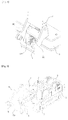
Fig. 1 is an exploded perspective view schematically showing a pipe fixing device for a construction machine in accordance with the present invention; -
Fig. 2 is a perspective view showing an assembled state in which first alignment hoses are preferentially disposed on a hose clamp to perform a pipe assembly work in a stepwise manner in accordance with the present invention; -
Fig. 3 is a perspective view showing an assembled state in which first alignment hoses are preferentially disposed and then second alignment hoses are disposed on a hose clamp to perform a pipe assembly work in a stepwise manner in accordance with the present invention; -
Fig. 4 is a perspective view showing an assembled state in which first alignment hoses and second alignment hoses are fixed to a boom base part in a stepwise manner in accordance with the present invention; and -
Fig. 5 is a schematic perspective view showing an example of an excavator to which a pipe fixing device for a construction machine in accordance with the present invention is applied. - Hereinafter, the preferred embodiments of the present invention will be described in detail with reference to the accompanying drawings.
- The matters defined in the description, such as the detailed construction and elements, are nothing but specific details provided to assist those of ordinary skill in the art in a comprehensive understanding of the invention, and the present invention is not limited to the embodiments disclosed hereinafter.
- In the drawings, for the sake of a clearer understanding of the present invention, sizes or shapes of elements illustrated in the drawings may be exaggerated for clarity and convenience of explanation. Also, the following terms particularly defined in consideration of the configuration and function of the present invention may vary according to an intention of a user or an operator or according to custom. Therefore, definition of such terms should be made based on overall contents of the specification.
- Here, the terms or words used in the specification and the claims of the present invention should not be construed as being typical or dictionary meanings, but should be construed as meanings and concepts conforming to the technical spirit of the present invention on the basis of the principle that an inventor can properly define the concepts of the terms in order to describe his or her invention in the best way.
- Prior to the description, a
reference numeral 10 denotes a hose clamp in accordance with the present invention, areference numeral 11 denotes a first support part of the hose clamp, areference numeral 12 denotes a second support part of the hose clamp, a reference numeral 14 denotes a guide seating part of the hose clamp, areference numeral 20 denotes a guide,reference numeral 24 denotes a cover fixing projection of the guide, and areference numeral 30 denotes a cover. - As shown in
Figs. 1 and4 , the pipe fixing device for a construction machineupper swing structure in accordance with an embodiment of the present invention can be installed at a base part of a
boom 2 or an arm 4 provided in an upper swing structure in various manners. - For example, typically, in the construction machine, hydraulic fluid is supplied to a
boom cylinder 2a, anarm cylinder 4a, and abucket cylinder 6a from a hydraulic pump included in an engine room 8 disposed at the rear of an operator's cab through a plurality of hydraulic hoses, i.e.,first alignment hoses 10A and thesecond alignment hoses 10B. In addition, an operator can easily plumb and assemble the first alignment hoses and the second alignment hoses separately in a stepwise process. - A pipe fixing device for a construction machine in accordance with the present invention includes: a
hose clamp 10 including a pair ofopposed fixing parts 13 attached to one side of anupper swing structure 3, afirst support part 11 formed extending between thefixing portions 13 and configured to support a plurality offirst alignment hoses 10A seated therein from the bottom at predetermined intervals, and asecond support part 12 formed to be spaced apart from thefirst support part 11 and configured to support a plurality ofsecond alignment hoses 10B seated therein from the top at predetermined intervals; aguide 20 including a pair of opposedclamp fixing parts 23 and fixedly coupled to thehose clamp 10 to restrict the movement of at least one of thefirst alignment hoses 10A in a state where the at least one of thefirst alignment hoses 10A is arranged in thefirst support part 11; and acover 30 securely fixed to theguide 20 to restrict the movement of at least one of thesecond alignment hoses 10B in a state where the at least one of thesecond alignment hoses 10B is arranged in thesecond support part 12. - In accordance with an embodiment of the present invention, the
hose clamp 10 includes a guide seating part 14 having a stepped recess formed thereon to fix theguide 20 to the hose clamp. In addition, theguide 20 includes a pair of opposedcover fixing projection 24 formed thereon to project between theclamp fixing parts 23. - Preferably, the
fixing parts 13 of thehose clamp 10 are attached to one side of a base part of aboom 2. In accordance with another embodiment of the present invention, thefixing parts 13 of thehost clamp 10 are attached to one side of a base part 9 of anarm cylinder 4a. - Meanwhile, in the pipe fixing device for a construction machine in accordance with the present invention, the
cover 30 includes a foreign substance blocking part. - The operation principle of the pipe fixing device for a construction machine in accordance with the present invention will be described hereinafter with reference to the accompanying drawings based on an embodiment in which the
fixing parts 13 of thehose clamp 10 are installed at a base part of theboom 2. - In the case where the
hose clamp 10 of the pipe fixing device for a construction machine in accordance with the present invention is assembled to the base part of theboom 2 of a general construction machine, the pair ofopposed fixing parts 13 formed at thehose clamp 10 are installed at the base part of theboom 2 disposed between a pair of opposed boom fixing brackets 1 of theupper swing structure 3. In this case, thefirst alignment hoses 10A, for example, hydraulic hoses for a work apparatus, i.e., an attachment, which are arranged at predetermined intervals, are supported in a close contact manner by thefirst support part 11 having a plurality of support surfaces formed thereon in an arcuate shape. - In this process, an operator can adjust the arrangement position of the
first alignment hoses 10A on thefirst support part 11. When a pair of opposedfirst fastening members 32 are fastened to the pair ofopposed fixing parts 13 of thehose clamp 10 after the completion of the adjustment of the arrangement position of thefirst alignment hoses 10A, thehose clamp 10 can be securely fixed to the base part of theboom 2. - Preferably, prior to the fixation of the
hose clamp 10 to the base part of theboom 2, theclamp fixing parts 23 of theguide 20 are seated on thefixing part 13 of thehose clamp 10 and a main body 21 of theguide 20 is mounted on the guide seating part 14 of thehose clamp 10. In this case, thefirst fastening members 32 are fixedly fastened to the base part of theboom 2 in a state where thefixing parts 13 of thehose clamp 10 and theclamp fixing parts 23 of theguide 20 are aligned with each other. - Thus, the
first alignment hoses 10A are fixedly held in thefirst support part 11 formed on the underside of thehose clamp 10 so that the horizontal and vertical movement of thefirst alignment hoses 10A is restricted. In this case, the main body 21 of theguide 20 additionally forms a hose supporting force in the guide seating part 14 of thehose clamp 10 that the vertical movement or displacement of thefirst alignment hoses 10A at a position adjacent to a central portion in the longitudinal direction of thehose clamp 10 can be limited. - In the meantime, the
second support part 12 of thehose clamp 10 is void, and the operator can seat thesecond alignment hoses 10B on thesecond support part 12. - In this case, the
second alignment hoses 10B, for example, hydraulic hoses for an option apparatus, which are arranged at predetermined intervals, are insertingly seated in thesecond support part 12 having a plurality of support surfaces formed thereon in an arcuate shape. - In this process, the operator can adjust the arrangement position of the
second alignment hoses 10B on thesecond support part 12. The operator places the cover 300 on thesecond alignment hoses 10B so that the inner surface of thecover 30 presses the top surfaces of thesecond alignment hoses 10B after the completion of the adjustment of the arrangement position of thesecond alignment hoses 10B. Subsequently, thesecond fastening members 33 are screwably fastened to screw holes of thecover fixing projections 24 formed protrudingly on the main body 21 of theguide 20 through fastening holes of thecover 30. - Thus, the
second alignment hoses 10B are fixedly held in thesecond support part 12 formed on the top surface of thehose clamp 10. Ultimately, thefirst alignment hoses 10A are fixedly held in thefirst support part 11 of thehose clamp 10, and then thesecond alignment hoses 10B are fixedly held in thesecond support part 12 of thehose clamp 10 so that the operator does not need a separate tool and a work for fixing the plurality of alignment hoses and components, and thus thefirst alignment hoses 10A and thesecond alignment hoses 10B can be easily assembled and installed in a stepwise manner. - Meanwhile, in the assembly of the
cover 30 in accordance with the present invention, when the foreignsubstance blocking part 31 is provided, rock fragments or foreign substances are further blocked from infiltrating into the fixed positions of thefirst alignment hoses 10A and thesecond alignment hoses 10B. For example, when rock fragments enter thehose clamp 10 side with them bouncing or infiltrate into thehose clamp 10 side from the top, the main body of thehose clamp 10 formed as a rubber member as well as the alignment hoses in which fluid flows may be damaged and the arrangement or alignment state of thefirst alignment hoses 10A and thesecond alignment hoses 10B may be deteriorated. In this case, thecover 30 including the foreignsubstance blocking part 31 protect thehose clamp 10 and the first andsecond alignment hoses - In various embodiments of the present invention, the fixing
parts 13 of thehose clamp 10 may be installed in proximity to the base part 9 side of anarm cylinder 4a, or may be installed in proximity to a hose connection part of abucket cylinder 6a. In this case, thefirst alignment hoses 10A are fixedly held in thefirst support part 11 of thehose clamp 10, and then thesecond alignment hoses 10B are fixedly held in thesecond support part 12 of thehose clamp 10 so that the operator does not need a separate tool and a work for fixing the plurality of alignment hoses and components. The operation principle in which thefirst alignment hoses 10A and thesecond alignment hoses 10B can be easily assembled and installed in a stepwise manner is the same as described above, and thus, a detailed description thereof will be omitted to avoid redundancy. - In accordance with the pipe fixing device for a construction machine of the present invention as constructed above, in assembling hoses connected to the work apparatus and the option apparatus on the upper swing structure, the arrangement and assembly of the plurality of hydraulic hoses which are used is performed in a process in which the first alignment hoses and the second alignment hoses are arranged separately so that the assembly defectives can be minimized, the assembly time can be reduced, and a convenience of the operator can be improved.
- While the present invention has been described in connection with the specific embodiments illustrated in the drawings, they are merely illustrative, and the invention is not limited to these embodiments. It is to be understood that various equivalent modifications and variations of the embodiments can be made by a person having an ordinary skill in the art without departing from the spirit and scope of the present invention. Therefore, the true technical scope of the present invention should not be defined by the above-mentioned embodiments but should be defined by the appended claims and equivalents thereof.
Claims (7)
- A pipe fixing device for a construction machine, comprising:a hose clamp including a pair of opposed fixing parts attached to one side of an upper swing structure, a first support part formed extending between the fixing portions and configured to support a plurality of first alignment hoses seated therein from the bottom at predetermined intervals, and a second support part formed to be spaced apart from the first support part and configured to support a plurality of second alignment hoses seated therein from the top at predetermined intervals;a guide including a pair of opposed clamp fixing parts and fixedly coupled to the hose clamp to restrict the movement of at least one of the first alignment hoses in a state where the at least one of the first alignment hoses is arranged in the first support part; anda cover securely fixed to the guide to restrict the movement of at least one of the second alignment hoses in a state where the at least one of the second alignment hoses is arranged in the second support part.
- The pipe fixing device according to claim 1, wherein the hose clamp comprises a guide seating part having a stepped recess formed thereon to fix the guide to the hose clamp.
- The pipe fixing device according to claim 2, wherein the guide comprises at one cover fixing projection formed thereon to project between the clamp fixing parts.
- The pipe fixing device according to claim 1 or 2, wherein the hose clamp is formed as a rubber member.
- The pipe fixing device according to claim 1 or 2, wherein the fixing parts of the hose clamp are attached to one side of a base part of a boom.
- The pipe fixing device according to claim 5, wherein the fixing parts of the host clamp are attached to one side of a base part of an arm cylinder.
- The pipe fixing device according to claim 5, wherein the cover further comprises a foreign substance blocking part.
Applications Claiming Priority (1)
| Application Number | Priority Date | Filing Date | Title |
|---|---|---|---|
| PCT/KR2013/004752 WO2014193002A1 (en) | 2013-05-30 | 2013-05-30 | Pipe fixing device for construction machine |
Publications (2)
| Publication Number | Publication Date |
|---|---|
| EP3006629A1 true EP3006629A1 (en) | 2016-04-13 |
| EP3006629A4 EP3006629A4 (en) | 2017-01-11 |
Family
ID=51989008
Family Applications (1)
| Application Number | Title | Priority Date | Filing Date |
|---|---|---|---|
| EP13885550.7A Withdrawn EP3006629A4 (en) | 2013-05-30 | 2013-05-30 | Pipe fixing device for construction machine |
Country Status (7)
| Country | Link |
|---|---|
| US (1) | US20160091123A1 (en) |
| EP (1) | EP3006629A4 (en) |
| KR (1) | KR20160006183A (en) |
| CN (1) | CN105247140A (en) |
| BR (1) | BR112015029531A2 (en) |
| CA (1) | CA2913144A1 (en) |
| WO (1) | WO2014193002A1 (en) |
Families Citing this family (14)
| Publication number | Priority date | Publication date | Assignee | Title |
|---|---|---|---|---|
| US10072391B2 (en) * | 2014-09-30 | 2018-09-11 | Kubota Corporation | Working machine |
| JP6856461B2 (en) * | 2017-06-27 | 2021-04-07 | 株式会社竹内製作所 | Steering structure of hydraulic hose |
| WO2021032421A1 (en) * | 2019-08-16 | 2021-02-25 | Volvo Truck Corporation | A modular mounting bracket |
| CN112460334A (en) * | 2020-12-15 | 2021-03-09 | 中国恩菲工程技术有限公司 | Pipeline fixing device |
| USD1019356S1 (en) * | 2022-02-09 | 2024-03-26 | Na Qiu | Cord organizer |
| CN115321272B (en) * | 2022-03-24 | 2024-10-29 | 中钢集团西安重机有限公司 | Hose motion system and method based on hose separation frame |
| USD1075484S1 (en) * | 2023-10-30 | 2025-05-20 | Ningbo Skl International Co., Ltd. | Cable organizer |
| USD1102876S1 (en) * | 2024-07-08 | 2025-11-25 | Xiamen Yameilongying Technology Co., Ltd. | Cord organizer |
| USD1118324S1 (en) * | 2024-08-28 | 2026-03-17 | Shenzhen Qifei Chuangxiang Technology Co., Ltd | Cord organizer |
| USD1073449S1 (en) * | 2025-01-17 | 2025-05-06 | Guoli Dai | Cord organizer |
| USD1081336S1 (en) * | 2025-03-19 | 2025-07-01 | Hong Jiang | Cable clip |
| USD1081335S1 (en) * | 2025-03-19 | 2025-07-01 | Hong Jiang | Cable clip |
| USD1079448S1 (en) * | 2025-03-19 | 2025-06-17 | Hong Jiang | Cable clip |
| USD1106804S1 (en) * | 2025-04-16 | 2025-12-23 | BingBing Sun | Cord organizer |
Family Cites Families (55)
| Publication number | Priority date | Publication date | Assignee | Title |
|---|---|---|---|---|
| GB527634A (en) * | 1939-03-28 | 1940-10-14 | Blackburn Aircraft Ltd | Improvements in means for bonding metal parts of aircraft and the like |
| GB589290A (en) * | 1944-07-10 | 1947-06-17 | Adel Prec Products Corp | Electric conduit supporting and bonding block |
| DE1601106U (en) * | 1949-10-10 | 1950-02-09 | Schalksmuehler Eisenwarenfabri | CLOTHES LIFT. |
| US3082890A (en) * | 1960-07-25 | 1963-03-26 | Deere & Co | Earth moving implement |
| GB952192A (en) * | 1960-11-07 | 1964-03-11 | Rolls Royce | Fastening device |
| US3099056A (en) * | 1960-11-07 | 1963-07-30 | Rolls Royce | Clamp |
| US3422884A (en) * | 1966-12-28 | 1969-01-21 | Baldwin Lima Hamilton Corp | Condenser tube bundles |
| US3742119A (en) * | 1971-11-11 | 1973-06-26 | Empire Prod Inc | Terminal housing |
| IT7722096U1 (en) * | 1977-09-01 | 1979-03-01 | Amp Italia | SUSPENSION CLAMP FOR ELECTRIC CABLES |
| US4131257A (en) * | 1977-11-14 | 1978-12-26 | Eby Company | Stacking cable clamp |
| JPH0137633B2 (en) * | 1979-07-16 | 1989-08-08 | Caterpillar Mitsubishi Ltd | |
| WO1982000843A1 (en) * | 1979-07-16 | 1982-03-18 | T Mueller | Guard structure for hydraulic conduits of a mobile apparatus |
| GB2059905A (en) * | 1979-09-24 | 1981-04-29 | Quraishi A H | Packing tubular members |
| JPS6131274Y2 (en) * | 1980-05-14 | 1986-09-11 | ||
| JPH0342311Y2 (en) * | 1985-05-23 | 1991-09-04 | ||
| US4658854A (en) * | 1985-06-03 | 1987-04-21 | Caterpillar Inc. | Conduit guarding and clamping device |
| US4934635A (en) * | 1988-12-20 | 1990-06-19 | Zsi, Inc. | Tubing clamp with hinged cushion |
| DE69004287T2 (en) * | 1989-02-16 | 1994-02-24 | Kubota Kk | Hydraulic pipe arrangement for a backhoe. |
| DE3913360C1 (en) * | 1989-04-22 | 1990-09-13 | Fa. A. Raymond, 7850 Loerrach, De | |
| DE3928320A1 (en) * | 1989-08-26 | 1991-03-14 | Drilltec Patents & Tech | DEVICE FOR STORING AND TRANSPORTING TUBES |
| US5071169A (en) * | 1990-09-04 | 1991-12-10 | Ford Motor Company | Tube coupling holder |
| US5098047A (en) * | 1990-10-18 | 1992-03-24 | Flex Rail, Inc. | Tube clamp |
| JP2563771Y2 (en) * | 1992-04-02 | 1998-02-25 | 株式会社クボタ | Construction machine hose clamp structure |
| US5205520A (en) * | 1992-05-26 | 1993-04-27 | Hydro-Craft, Inc. | Retaining block for clamping system |
| US5375888A (en) * | 1993-02-17 | 1994-12-27 | The Victaulic Company Of Japan Limited | Pipe coupling for repair |
| DE9304363U1 (en) * | 1993-03-18 | 1994-04-21 | Krone Ag, 14167 Berlin | Device for clamping cables (cable clamping element) |
| FR2744193B1 (en) * | 1996-01-31 | 1998-02-27 | Valeo Climatisation | DEVICE FOR FIXING AT LEAST ONE TUBING RELATIVE TO A HOUSING, PARTICULARLY FOR A VEHICLE HEATING SYSTEM |
| US5996945A (en) * | 1997-10-31 | 1999-12-07 | Caterpillar Inc. | Hose clamp assembly offset mounting capability |
| DE29920652U1 (en) * | 1999-11-24 | 2000-01-20 | Liebherr-Hydraulikbagger GmbH, 88457 Kirchdorf | Industrial handle, especially for handling equipment |
| DE19959185A1 (en) * | 1999-12-08 | 2001-06-28 | Bethke Kunststofftechnik Gmbh | Cable entry |
| US6783101B2 (en) * | 2000-07-26 | 2004-08-31 | Brook H. Knotts | Clamp for securing multiple, spaced-apart tubes |
| JP3668109B2 (en) * | 2000-08-15 | 2005-07-06 | 日立建機株式会社 | Construction machinery |
| JP2002161851A (en) * | 2000-11-24 | 2002-06-07 | Hitachi Constr Mach Co Ltd | Hydraulic pump device |
| US6561466B1 (en) * | 2002-02-20 | 2003-05-13 | Mitchell W. Myers | Interchangeable hose, cable, and conduit support mechanism |
| US7080864B2 (en) * | 2002-05-03 | 2006-07-25 | Drilltec Patents & Technologies Company, Inc. | Apparatus for shipping and storing elongated members |
| FR2843438B1 (en) * | 2002-08-09 | 2005-02-11 | Amphenol Air Lb | DEVICE FOR MAINTAINING PIPING SYSTEMS |
| JP4004041B2 (en) | 2002-09-05 | 2007-11-07 | 株式会社小松製作所 | Hydraulic piping structure of left and right swing type work equipment |
| JP4060755B2 (en) * | 2003-05-30 | 2008-03-12 | 日立建機株式会社 | Hose clamp device |
| US7464966B2 (en) * | 2004-06-30 | 2008-12-16 | Tokai Rubber Industries, Inc. | Through-panel fixing device for piping member |
| JP4720499B2 (en) * | 2005-12-28 | 2011-07-13 | コベルコ建機株式会社 | Work machine |
| JP4705056B2 (en) * | 2007-02-16 | 2011-06-22 | 日立建機株式会社 | Construction machinery |
| PL2297020T3 (en) * | 2008-07-11 | 2013-02-28 | Palfinger Ag | Vehicle crane having hose guide |
| US7922012B2 (en) * | 2008-07-24 | 2011-04-12 | Power Bus Way Ltd. | Cable tray |
| JP4954159B2 (en) * | 2008-08-05 | 2012-06-13 | 日立建機株式会社 | Hose clamp device |
| US20100123048A1 (en) * | 2008-11-18 | 2010-05-20 | Pollard Jr Michael E | Cable bus support block and system |
| US8074945B2 (en) * | 2008-12-15 | 2011-12-13 | Caterpillar Inc. | Conduit mounting system |
| JP5003711B2 (en) * | 2009-04-02 | 2012-08-15 | コベルコクレーン株式会社 | Piping clamp device |
| US8291551B2 (en) * | 2009-04-22 | 2012-10-23 | Deere & Company | Clamp assembly |
| KR101121706B1 (en) * | 2009-10-26 | 2012-03-09 | 볼보 컨스트럭션 이큅먼트 에이비 | fixing device of hydraulic pipe of construction equipment |
| JP5286305B2 (en) * | 2010-02-22 | 2013-09-11 | 川崎重工業株式会社 | Waterproof device for electric cable introduction part of railway vehicles |
| DE102011101366A1 (en) * | 2010-05-12 | 2011-11-17 | Helmut Hiendl | Device i.e. cable clip, for bundling, arranging and fixing of e.g. cable, has detent surface provided in recess of base body by locking unit in closed position, where detect surface is provided with mating surface in recess |
| JP5602944B2 (en) * | 2010-05-17 | 2014-10-08 | ボルボ コンストラクション イクイップメント アーベー | Hydraulic piping fixing device for construction machinery |
| JP5177201B2 (en) * | 2010-10-20 | 2013-04-03 | コベルコ建機株式会社 | Piping clamp for construction machinery |
| JP5525488B2 (en) * | 2011-06-24 | 2014-06-18 | 日立建機株式会社 | Swivel construction machine |
| NO334645B1 (en) * | 2012-02-17 | 2014-05-05 | Smed T Kristiansen As | Device by tube support |
-
2013
- 2013-05-30 CA CA2913144A patent/CA2913144A1/en not_active Abandoned
- 2013-05-30 CN CN201380077067.9A patent/CN105247140A/en active Pending
- 2013-05-30 WO PCT/KR2013/004752 patent/WO2014193002A1/en not_active Ceased
- 2013-05-30 KR KR1020157033169A patent/KR20160006183A/en not_active Abandoned
- 2013-05-30 EP EP13885550.7A patent/EP3006629A4/en not_active Withdrawn
- 2013-05-30 BR BR112015029531A patent/BR112015029531A2/en not_active IP Right Cessation
- 2013-05-30 US US14/893,582 patent/US20160091123A1/en not_active Abandoned
Also Published As
| Publication number | Publication date |
|---|---|
| WO2014193002A1 (en) | 2014-12-04 |
| CA2913144A1 (en) | 2014-12-04 |
| EP3006629A4 (en) | 2017-01-11 |
| US20160091123A1 (en) | 2016-03-31 |
| KR20160006183A (en) | 2016-01-18 |
| BR112015029531A2 (en) | 2017-07-25 |
| CN105247140A (en) | 2016-01-13 |
Similar Documents
| Publication | Publication Date | Title |
|---|---|---|
| US20160091123A1 (en) | Pipe fixing device for construction machine | |
| US8920105B2 (en) | Rotation-type construction machine | |
| US8950538B2 (en) | Working machine | |
| US9206585B2 (en) | Working machine having console box | |
| EP2792867A1 (en) | Exhaust apparatus of construction machine | |
| EP2829499A1 (en) | Outrigger connection locking device | |
| KR101834306B1 (en) | a work scaffold | |
| EP2653620A1 (en) | Device for fixing hydraulic pipe of boom swing type excavator | |
| EP1462576A2 (en) | Piping arrangement for swing type hydraulic excavators | |
| EP2366836A2 (en) | Construction machine | |
| EP2687635A1 (en) | Hydraulic oil tank attachment structure of construction machine | |
| JP2004100173A (en) | Hydraulic piping structure of left and right swing type work equipment | |
| EP3095923A1 (en) | Handrail for construction equipment | |
| JP6064773B2 (en) | Hydraulic hose arrangement structure | |
| EP3396072B1 (en) | Compact construction machine | |
| WO2016063395A1 (en) | Controller assembly and work machine cab | |
| JP2004250990A (en) | Piping structure in construction machinery | |
| EP2796622A1 (en) | Pilot valve attachment structure of construction machine | |
| JP6972777B2 (en) | Sanitary cleaning equipment and toilet equipment | |
| EP2868813B1 (en) | Construction machine with pilot hoses | |
| JP2008231693A (en) | Clamp device for delivery hose of swivel work machine | |
| JP2011241587A (en) | Piping structure for suction pipe of construction machine | |
| JP2015183511A (en) | Faucet device | |
| US10106958B2 (en) | Working machine | |
| JP2017080187A (en) | Support device and bathing support device |
Legal Events
| Date | Code | Title | Description |
|---|---|---|---|
| PUAI | Public reference made under article 153(3) epc to a published international application that has entered the european phase |
Free format text: ORIGINAL CODE: 0009012 |
|
| 17P | Request for examination filed |
Effective date: 20151126 |
|
| AK | Designated contracting states |
Kind code of ref document: A1 Designated state(s): AL AT BE BG CH CY CZ DE DK EE ES FI FR GB GR HR HU IE IS IT LI LT LU LV MC MK MT NL NO PL PT RO RS SE SI SK SM TR |
|
| AX | Request for extension of the european patent |
Extension state: BA ME |
|
| DAX | Request for extension of the european patent (deleted) | ||
| A4 | Supplementary search report drawn up and despatched |
Effective date: 20161209 |
|
| RIC1 | Information provided on ipc code assigned before grant |
Ipc: F16L 3/08 20060101ALI20161205BHEP Ipc: F16L 3/22 20060101ALI20161205BHEP Ipc: F16L 3/223 20060101ALI20161205BHEP Ipc: E02F 9/22 20060101AFI20161205BHEP |
|
| STAA | Information on the status of an ep patent application or granted ep patent |
Free format text: STATUS: THE APPLICATION IS DEEMED TO BE WITHDRAWN |
|
| 18D | Application deemed to be withdrawn |
Effective date: 20170714 |