US4934635A - Tubing clamp with hinged cushion - Google Patents
Tubing clamp with hinged cushion Download PDFInfo
- Publication number
- US4934635A US4934635A US07/287,007 US28700788A US4934635A US 4934635 A US4934635 A US 4934635A US 28700788 A US28700788 A US 28700788A US 4934635 A US4934635 A US 4934635A
- Authority
- US
- United States
- Prior art keywords
- cylindrical member
- clamp
- cushion insert
- side walls
- assembly
- Prior art date
- Legal status (The legal status is an assumption and is not a legal conclusion. Google has not performed a legal analysis and makes no representation as to the accuracy of the status listed.)
- Expired - Lifetime
Links
- 239000012530 fluid Substances 0.000 description 13
- 125000006850 spacer group Chemical group 0.000 description 3
- 230000000712 assembly Effects 0.000 description 2
- 238000000429 assembly Methods 0.000 description 2
- 238000001746 injection moulding Methods 0.000 description 2
- 239000000463 material Substances 0.000 description 2
- 239000004033 plastic Substances 0.000 description 2
- 230000000717 retained effect Effects 0.000 description 2
- RYGMFSIKBFXOCR-UHFFFAOYSA-N Copper Chemical compound [Cu] RYGMFSIKBFXOCR-UHFFFAOYSA-N 0.000 description 1
- 229910000831 Steel Inorganic materials 0.000 description 1
- 229910052802 copper Inorganic materials 0.000 description 1
- 239000010949 copper Substances 0.000 description 1
- 230000008878 coupling Effects 0.000 description 1
- 238000010168 coupling process Methods 0.000 description 1
- 238000005859 coupling reaction Methods 0.000 description 1
- 239000013536 elastomeric material Substances 0.000 description 1
- 230000008030 elimination Effects 0.000 description 1
- 238000003379 elimination reaction Methods 0.000 description 1
- 238000009434 installation Methods 0.000 description 1
- 235000015250 liver sausages Nutrition 0.000 description 1
- 230000004048 modification Effects 0.000 description 1
- 238000012986 modification Methods 0.000 description 1
- 239000010959 steel Substances 0.000 description 1
- 229920002725 thermoplastic elastomer Polymers 0.000 description 1
Images


Classifications
-
- F—MECHANICAL ENGINEERING; LIGHTING; HEATING; WEAPONS; BLASTING
- F16—ENGINEERING ELEMENTS AND UNITS; GENERAL MEASURES FOR PRODUCING AND MAINTAINING EFFECTIVE FUNCTIONING OF MACHINES OR INSTALLATIONS; THERMAL INSULATION IN GENERAL
- F16L—PIPES; JOINTS OR FITTINGS FOR PIPES; SUPPORTS FOR PIPES, CABLES OR PROTECTIVE TUBING; MEANS FOR THERMAL INSULATION IN GENERAL
- F16L55/00—Devices or appurtenances for use in, or in connection with, pipes or pipe systems
- F16L55/02—Energy absorbers; Noise absorbers
- F16L55/033—Noise absorbers
- F16L55/035—Noise absorbers in the form of specially adapted hangers or supports
-
- F—MECHANICAL ENGINEERING; LIGHTING; HEATING; WEAPONS; BLASTING
- F16—ENGINEERING ELEMENTS AND UNITS; GENERAL MEASURES FOR PRODUCING AND MAINTAINING EFFECTIVE FUNCTIONING OF MACHINES OR INSTALLATIONS; THERMAL INSULATION IN GENERAL
- F16L—PIPES; JOINTS OR FITTINGS FOR PIPES; SUPPORTS FOR PIPES, CABLES OR PROTECTIVE TUBING; MEANS FOR THERMAL INSULATION IN GENERAL
- F16L3/00—Supports for pipes, cables or protective tubing, e.g. hangers, holders, clamps, cleats, clips, brackets
- F16L3/08—Supports for pipes, cables or protective tubing, e.g. hangers, holders, clamps, cleats, clips, brackets substantially surrounding the pipe, cable or protective tubing
- F16L3/10—Supports for pipes, cables or protective tubing, e.g. hangers, holders, clamps, cleats, clips, brackets substantially surrounding the pipe, cable or protective tubing divided, i.e. with two or more members engaging the pipe, cable or protective tubing
-
- Y—GENERAL TAGGING OF NEW TECHNOLOGICAL DEVELOPMENTS; GENERAL TAGGING OF CROSS-SECTIONAL TECHNOLOGIES SPANNING OVER SEVERAL SECTIONS OF THE IPC; TECHNICAL SUBJECTS COVERED BY FORMER USPC CROSS-REFERENCE ART COLLECTIONS [XRACs] AND DIGESTS
- Y10—TECHNICAL SUBJECTS COVERED BY FORMER USPC
- Y10T—TECHNICAL SUBJECTS COVERED BY FORMER US CLASSIFICATION
- Y10T24/00—Buckles, buttons, clasps, etc.
- Y10T24/14—Bale and package ties, hose clamps
- Y10T24/1412—Bale and package ties, hose clamps with tighteners
- Y10T24/1441—Tangential screw
Definitions
- the present invention relates generally to a two-piece clamp for securing elongated cylindrical members, more particularly to, a two-piece clamp with a cushion for securing an elongated cylindrical member therein.
- a clamp assembly having two clamp halves and a stud non-rotatably anchored on one of the clamp halves.
- the stud includes an integral or separable spacer portion which controls the clamping force exerted on the tubing and prevents deformation of the tubing when the stud assembly is tightened.
- the patented clamp assembly includes a cushion insert for indirectly engaging the tubing through the elastomeric cushion insert which partially encircles the tubing and is retained within the clamp assembly as illustrated in FIG. 1.
- the cushion insert 10 includes a generally planar base portion 12 with upwardly and inwardly extending arcuate side walls 14 that substantially encompass the tubing. The ends of the side flanges 14 form a gap 16.
- the side walls 14 form a smooth continuous passageway 18 extending axially through the cushion insert 10 in which the tubing is disposed.
- the side walls 14 also include end flanges 20 extending outwardly at the ends of the cushion insert 10 to limit the relative axial movement between a clamp half disposed between the end flanges 20 and the cushion insert 10.
- One disadvantage of the above patented clamp assembly is that when small diameter tubes are used, e.g. one-half inch diameter, a large amount of force must be exerted by the operator on the cushion insert to spread the side walls of the cushion insert apart to fit over and about the tube. As a result, the cushion inserts were slid or disposed about one end of the tubing and moved to the desired position along the tubing.
- Another disadvantage of the above patented clamp assembly is that the cushion insert is used for generally continuous tubing of constant diameter which is used for fluid lines running from a power supply to a machine or the like, e.g. in the fluid power market.
- the patented clamp assembly is used for typically thin walled copper tubing to prevent the tubing from being deformed if the clamp assembly is over-tightened.
- the spacer prevents the clamp halves from being tightened together to the extent required to prevent leaking of a junction between tubing or relative movement between the tubing and clamp assembly.
- the rail mounted clamp assembly 21 includes a junction adapter or fitting 22 having a square or hexagon nut 23 formed on its outer surface with male or female threaded ends 24.
- the assembly also includes a rectangular tube or housing 25 about the nut 23 which is adapted to be secured to a support surface.
- a pair of cylindrical members 26 pass through the housing 25 on both sides of the adapter 22 to prevent rotation of the adapter 22.
- the cylindrical member 26 has a nut or base 27 at one end abutting the outside of the housing 25 and a fastener 28 which threadably engages the other end of the cylindrical member 26 to secure it to the housing 25.
- one object of the present invention to provide an easy-to-use cushion insert to fit over tubing or other cylindrical members of relatively small diameters.
- the present invention is a clamp assembly having two clamp halves.
- a cushion insert is disposed within the clamp halves to retain a tube or other cylindrical member within the clamp assembly.
- the cushion insert includes means for allowing the cushion insert to flex and be disposed about the tube or other cylindrical member.
- the clamp assembly can be used for fluid lines in the fluid power market. Also, the clamp assembly can be used with a channel mounted clamping system. Another advantage of the present invention is that the assembly does not have to be disassembled to attach the tubing or other cylindrical member to it. A further advantage of the present invention is that it can be used for discontinuous tubing, fittings or other cylindrical members. A still further advantage of the present invention is that the cushion insert is molded to prevent rotation of a tube or fitting within the clamp assembly. Another advantage of the present invention is that the cushion insert is more flexible to allow the cushion insert to be disposed over small diameter tubing, providing greater operator convenience. A further advantage of the present invention is that elimination of a spacer between the clamp halves allows the clamp halves to be tightened as much as desired.
- FIG. 1 is a perspective view of a prior art elastomeric cushion insert.
- FIG. 2 is a perspective view of a prior art clamp assembly for a rail mounted system used in the fluid power market;
- FIG. 3 is a perspective view of a cushion insert according to the principles of the present invention.
- FIG. 4 is a front elevational view of the cushion insert of FIG. 3 with the side walls spread apart in phantom lines.
- FIG. 5 is a front elevational view of a tubing clamp including the cushion insert of FIG. 3 secured to a channel.
- FIG. 6 is a sectional view of the tubing clamp of FIG. 5 taken along line 6--6.
- FIG. 7 is a sectional view of the tubing clamp of FIG. 6 taken along line 7--7 shown in full view.
- FIG. 8 is an elevational view of a mold cavity for making the cushion insert of FIG. 3.
- FIG. 9 is a front elevational view of the core insert for making the cushion insert of FIG. 3.
- FIG. 10 is a side elevational view of the core insert of FIG. 9.
- FIG. 11 is a perspective view of a first alternate cushion insert according to the principles of the present invention.
- FIG. 12 is a perspective view of a second alternate cushion insert according to the principles of the present invention.
- the cushion insert 30 constructed in accordance with the principles of the present invention is shown.
- the cushion insert 30 includes a generally planar base portion 32 with upwardly and inwardly extending arcuate side walls 34.
- the ends of the side walls 34 form a space or gap 36 that allows the side walls 34 to be partially flexed to fit over a tube, conduit, or fitting (not shown in the figure) in a passageway 38 defined by the side walls 34.
- the passageway 38 extends axially through the cushion insert 30.
- the side walls 34 also include end flanges 40 extending outwardly and partially upwardly at the ends of the cushion insert 30 to limit relative axial movement between the cushion insert 30 and a clamp half to be described disposed between the end flanges 40.
- the cushion insert 30 may be made of an elastomeric material such as a thermoplastic elastomer. This material allows the cushion insert 30 to be molded by conventional injection molding.
- the cushion insert 30 includes a generally arcuate first interior wall 42 extending radially inwardly into the passageway 38.
- the cushion insert 30 further includes a generally arcuate second interior wall 44 spaced axially from the first interior wall 42 and extending radially inwardly into the passageway 38.
- the passageway 38 has a shaped portion 46 between the first and second interior walls 42 and 44 formed to a predetermined shape such as that of a hexagon. It should be appreciated that a corresponding object such as a fitting 60 to be described is disposed in the shaped portion 46 of the passageway 38.
- the shaped portion 46 is molded to secure the fitting 60 and prevent the fitting 60 from rotating or turning even when wrench force is applied.
- the fitting 60 is also limited from axial movement by the first and second interior walls 42 and 44.
- the cushion insert 30 also includes a slot or groove 48 formed axially along the bottom surface of the passageway 38.
- the slot 48 acts as a living hinge and allows additional flexure of the side walls 34 permitting them to be spread apart and over a tube, conduit or fitting 60, especially at small outside diameters, e.g. outside diameter of 0.5 inches as illustrated in FIG. 4. This makes installation faster and easier, saving money in labor time as opposed to slipping the cushion insert over one end of the tubing or the like as in the past.
- the slot 48 is used, preferably, for passageways 38 having a diameter of one-quarter (1/4) to one and five-eighths (15/8) inches.
- the slot 48 also has a width of, preferably, 0.03 inches.
- the slot 48 also includes inclined side walls 49 having an angle of, preferably, thirty (30) degrees with a vertical axis passing through the slot 48 and perpendicular to the base portion 32. It should also be appreciated that the width of slot 48 and inclined side walls 49 allows flexure of the side walls 34 to accomodate tubing or the like having a diameter no greater than the diameter of the passageway 38.
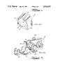
- the clamp assembly 50 comprises first and second clamp halves 52 and 54 which are detachably secured together by means of a threaded fastener 56 and an internally threaded nut 58.
- the fastener 56 is non-rotatable and press fit into an aperture 62 (FIG. 6) of the clamp half 52.
- the nut 58 is an elastic stopnut.
- the cushion insert 30 is provided inside the first and second clamp halves 52 and 54 for indirectly engaging a cylindrical member such as a tube, conduit or fitting, generally indicated at 60, through the cushion insert 30 which partially encircles the fitting 60 and is retained within the clamp assembly 50.
- the first and second clamp halves 52 and 54 each include a corresponding aperture 62 and 64, respectively, on one end for receiving the fastener 56.
- the first and second clamp halves 52 and 54 also include generally "T" shaped channel interlocking feet 66 and 68, respectively, provided on the opposite end thereof for engaging a generally U-shaped channel 70 having generally C-shaped ends 72.
- the fitting 60 is generally elongated tubular or cylindrical in shape and includes a gripping portion 74 extending radially outwardly from the outer surface of the fitting 60.
- the gripping portion 74 has a predetermined shape such as a hexagon and is disposed in the corresponding shaped portion 46 of the passageway 38.
- the first 42 and second 44 interior walls limit the axial movement of the gripping portion 74 of the fitting 60 within the passageway 38.
- the fitting 60 also includes end portions 76 and 78 which may be male or female to allow a corresponding female or male coupling (not shown) to be threadably secured to the fitting 60.
- the base portion 32 may have portions removed from it axially interior of its ends to form pockets 79 which add to the flexibility of the side walls 34 and reduce material cost.
- a mold cavity 80 for making the cushion insert 30 is shown.
- the mold cavity 80 fits in a mold (not shown) to allow the cushion insert 30 to be formed by conventional injection molding.
- the mold cavity 80 is generally rectangular and includes a pocket 82 formed in its upper surface 84.
- the pocket 82 includes sides 86 which extend generally vertically downward to an arcuate bottom 88.
- the pocket 82 also includes radially extending ends 90 partially along the sides 86.
- the pocket 82 further includes a slot or groove 92 extending axially along its bottom 88.
- a core insert, generally indicated at 94, is disposed in the slot 92 and spaced from the sides 86 and bottom 86 within the pocket 82.
- the core insert 94 includes a pair of blocks 96 and 98 which are generally rectangular in shape and a generally elongated cylindrical member 100.
- the block 98 includes inclined side portions 99 which form the inclined side walls 49 of the slot 48.
- the cylindrical member 100 includes opposite disposed slots 102 and 104 formed axially along its outer surface.
- the first block 96 is partially disposed in the slot 92 of the pocket 82 and the slot 102 of the cylindrical member 100.
- the second block 98 is partially disposed in the slot 104 and extends upwardly in the pocket 82 of the mold cavity 80.
- the cylindrical member 100 includes a forming portion 106 extending radially outwardly from its outer surface and has a predetermined shape such as a hexagon.
- the cylindrical member 100 also has end flanges 108 and 110 extending radially outwardly at its ends. It should be appreciated that the forming portion 106 forms the shaped portion 46 of the cushion insert 30 and spaces 111 formed between the end flanges 108 and 110 which form the interior walls 42 and 44.
- the cushion insert 130 has a smooth continuous passageway 138 with a slot 148 having inclined side walls 149 formed, preferably, axially along the bottom of the passageway 138.
- FIG. 12 an alternate embodiment 230 of the cushion insert 130 of FIG. 9 is shown. Like parts have like numerals increased by one hundred.
- the cushion insert 230 includes a slot 248 formed axially along the outer surface of the base portion 232.
- the slot 248 also has inclined side walls 249.
- the slot 248 on the outer surface of the base portion 232 gives a more desirable aesthetic appearance to the cushion insert 230. It should be appreciated that the slots 148 and 248 act as a living hinge similar to slot 48 and allow additional flexure of the side walls.
Abstract
Description
Claims (21)
Priority Applications (2)
| Application Number | Priority Date | Filing Date | Title |
|---|---|---|---|
| US07/287,007 US4934635A (en) | 1988-12-20 | 1988-12-20 | Tubing clamp with hinged cushion |
| US07/450,676 US4997148A (en) | 1988-12-20 | 1989-12-14 | Tubing clamp with hinged cushion |
Applications Claiming Priority (1)
| Application Number | Priority Date | Filing Date | Title |
|---|---|---|---|
| US07/287,007 US4934635A (en) | 1988-12-20 | 1988-12-20 | Tubing clamp with hinged cushion |
Related Child Applications (1)
| Application Number | Title | Priority Date | Filing Date |
|---|---|---|---|
| US07/450,676 Continuation US4997148A (en) | 1988-12-20 | 1989-12-14 | Tubing clamp with hinged cushion |
Publications (1)
| Publication Number | Publication Date |
|---|---|
| US4934635A true US4934635A (en) | 1990-06-19 |
Family
ID=23101074
Family Applications (1)
| Application Number | Title | Priority Date | Filing Date |
|---|---|---|---|
| US07/287,007 Expired - Lifetime US4934635A (en) | 1988-12-20 | 1988-12-20 | Tubing clamp with hinged cushion |
Country Status (1)
| Country | Link |
|---|---|
| US (1) | US4934635A (en) |
Cited By (31)
| Publication number | Priority date | Publication date | Assignee | Title |
|---|---|---|---|---|
| US4997148A (en) * | 1988-12-20 | 1991-03-05 | Zsi, Inc. | Tubing clamp with hinged cushion |
| US5205520A (en) * | 1992-05-26 | 1993-04-27 | Hydro-Craft, Inc. | Retaining block for clamping system |
| US5215281A (en) * | 1991-09-27 | 1993-06-01 | Zsi, Inc. | Two-piece cushion insert for U-bolt clamp assembly |
| US5946772A (en) * | 1997-09-16 | 1999-09-07 | Emco Enterprises, Inc. | Cover for a door closure |
| US5984243A (en) * | 1997-09-09 | 1999-11-16 | Thomas & Betts International, Inc. | Pipe cushion |
| US6105216A (en) * | 1999-02-25 | 2000-08-22 | Hydra-Zorb Co. | Clamp assembly |
| US6467507B1 (en) * | 2002-03-20 | 2002-10-22 | Visteon Global Technologies, Inc. | Clip for attaching a component to a plastic material mounting surface |
| US6601802B1 (en) | 1999-12-30 | 2003-08-05 | Lsp Products Group Inc | Method for making extruded acoustic pipe support |
| US6669150B2 (en) * | 2001-05-31 | 2003-12-30 | Illinois Tool Works Inc. | Clip assembly with positive locating features |
| US6682025B2 (en) * | 2001-12-26 | 2004-01-27 | Thomas M. Turner | Pipe support |
| US20050005982A1 (en) * | 2003-07-10 | 2005-01-13 | Brian Muscat | Power steering noise and vibration attenuator |
| US20050163561A1 (en) * | 2004-01-23 | 2005-07-28 | Weger Kris A. | Adjustable pipe clamp assembly |
| US20050211847A1 (en) * | 2004-03-29 | 2005-09-29 | The Boeing Company | Variable-duct support assembly |
| US20060076462A1 (en) * | 2004-10-08 | 2006-04-13 | Ramon Ceravalls Pujol | Clamp |
| US20070049073A1 (en) * | 2005-06-09 | 2007-03-01 | Hill Douglas C | Clip for flexible armored cable |
| US20070145198A1 (en) * | 2005-12-23 | 2007-06-28 | Eugene Miller | Rotating cushion for a tubing clamp |
| US20080203247A1 (en) * | 2005-06-09 | 2008-08-28 | Hill Douglas C | Clip |
| US20090271959A1 (en) * | 2008-04-30 | 2009-11-05 | Cazalet Michael E | Modular clamping system |
| US20100265728A1 (en) * | 2009-01-21 | 2010-10-21 | Melittas William S | Light Bulb Holder |
| US20110126934A1 (en) * | 2008-04-28 | 2011-06-02 | Thuesen Joergen | Clamp for securing a pipe to a supporting structure |
| US20130240682A1 (en) * | 2012-03-15 | 2013-09-19 | Airbus Operations (S.A.S.) | Device for attaching an electrical harness in an aircraft |
| US9074715B2 (en) | 2013-03-15 | 2015-07-07 | Zsi, Inc. | Cushion insert for a tubing clamp and method of replacement |
| US20150204474A1 (en) * | 2014-01-23 | 2015-07-23 | Hans-Jurgen Guido | After the mass-spring principle operating vibration absorber |
| US20150219132A1 (en) * | 2014-02-01 | 2015-08-06 | GM Global Technology Operations LLC | Retaining clip for at least one elongate element |
| US20160091123A1 (en) * | 2013-05-30 | 2016-03-31 | Seong-Geun Yun | Pipe fixing device for construction machine |
| USD756207S1 (en) * | 2014-04-15 | 2016-05-17 | General Electric Company | Center pivot |
| US20160265565A1 (en) * | 2015-03-13 | 2016-09-15 | Omron Corporation | Fixture |
| WO2016205957A1 (en) * | 2015-06-25 | 2016-12-29 | Hifi Engineering Inc. | A clamp and a method of clamping |
| US9903512B2 (en) * | 2015-05-26 | 2018-02-27 | Georg Fischer Llc | Pipe clamp for strut system |
| US10264736B2 (en) * | 2013-12-09 | 2019-04-23 | Thriving Systems Design, Llc | Radially slotted annular coupling system |
| CN110778799A (en) * | 2019-11-08 | 2020-02-11 | 哈尔滨锅炉厂有限责任公司 | Clamping type pipe seat and anti-rotation clamping block structure of pipe clamp cross arm |
Citations (25)
| Publication number | Priority date | Publication date | Assignee | Title |
|---|---|---|---|---|
| US2399899A (en) * | 1944-04-10 | 1946-05-07 | Tinnerman Products Inc | Bonding clamp |
| US2440469A (en) * | 1944-10-23 | 1948-04-27 | Adel Prec Products Corp | Multiple clip and bracket |
| US2872141A (en) * | 1953-11-27 | 1959-02-03 | Gen Motors Corp | Cable hanger |
| US2998217A (en) * | 1959-07-06 | 1961-08-29 | T A Mfg Corp | Quick-opening line supporting clamp |
| US3154281A (en) * | 1962-02-20 | 1964-10-27 | Frank Charles | Holder for electronic components |
| US3341232A (en) * | 1966-09-09 | 1967-09-12 | United States Pipe Foundry | Pipe joint |
| US3370815A (en) * | 1965-09-13 | 1968-02-27 | Lamb Co F Jos | Shock absorbing pad for conduit clamping device |
| US3397431A (en) * | 1967-05-12 | 1968-08-20 | Hydro Craft Inc | Tube clamp assembly |
| US3414220A (en) * | 1966-12-30 | 1968-12-03 | Hydro Craft Inc | Clamp means |
| US3429014A (en) * | 1967-12-04 | 1969-02-25 | Castle Ind Inc Of California | Clamp assembly for confronting annular flanges |
| US3486726A (en) * | 1968-07-09 | 1969-12-30 | Robert D Kindorf | Universal pipe clamp |
| US3521842A (en) * | 1968-05-06 | 1970-07-28 | Lamb Co F Jos | Spring clamp for mounting conduit on a channel support |
| US3606218A (en) * | 1969-03-21 | 1971-09-20 | Gen Dynamics Corp | Sound and vibration isolation support |
| US3684223A (en) * | 1970-10-20 | 1972-08-15 | Duane D Logsdon | Pipe clamp |
| US3843083A (en) * | 1972-11-09 | 1974-10-22 | Wonder Piles | Mounting apparatus for portable device |
| US3848839A (en) * | 1972-01-25 | 1974-11-19 | G Tillman | Conduit support clamp |
| US4037810A (en) * | 1976-01-12 | 1977-07-26 | Indian Head Inc. | Pipe bracket and clamp |
| US4185802A (en) * | 1978-09-13 | 1980-01-29 | Fischer Sherman, Inc. | Anti-vibration pad for pipe support clamp |
| US4417755A (en) * | 1974-10-07 | 1983-11-29 | Familian Corp. | Pipe coupling |
| US4442994A (en) * | 1982-02-02 | 1984-04-17 | Logsdon Duane D | Pipe hanger capable of totally encircling a pipe |
| US4516296A (en) * | 1983-10-05 | 1985-05-14 | Zsi, Inc. | Tubing clamp and method of making the same |
| US4612680A (en) * | 1984-03-26 | 1986-09-23 | Harumoto Iron Works Co., Ltd. | Cover joint and armor for bridge cable |
| US4614321A (en) * | 1984-04-30 | 1986-09-30 | A. Raymond | Pipe clip |
| US4640479A (en) * | 1983-01-31 | 1987-02-03 | All States Inc. | Strain relief grommet |
| US4653782A (en) * | 1985-02-18 | 1987-03-31 | British Gas Corporation | Pipe repair clamp |
-
1988
- 1988-12-20 US US07/287,007 patent/US4934635A/en not_active Expired - Lifetime
Patent Citations (25)
| Publication number | Priority date | Publication date | Assignee | Title |
|---|---|---|---|---|
| US2399899A (en) * | 1944-04-10 | 1946-05-07 | Tinnerman Products Inc | Bonding clamp |
| US2440469A (en) * | 1944-10-23 | 1948-04-27 | Adel Prec Products Corp | Multiple clip and bracket |
| US2872141A (en) * | 1953-11-27 | 1959-02-03 | Gen Motors Corp | Cable hanger |
| US2998217A (en) * | 1959-07-06 | 1961-08-29 | T A Mfg Corp | Quick-opening line supporting clamp |
| US3154281A (en) * | 1962-02-20 | 1964-10-27 | Frank Charles | Holder for electronic components |
| US3370815A (en) * | 1965-09-13 | 1968-02-27 | Lamb Co F Jos | Shock absorbing pad for conduit clamping device |
| US3341232A (en) * | 1966-09-09 | 1967-09-12 | United States Pipe Foundry | Pipe joint |
| US3414220A (en) * | 1966-12-30 | 1968-12-03 | Hydro Craft Inc | Clamp means |
| US3397431A (en) * | 1967-05-12 | 1968-08-20 | Hydro Craft Inc | Tube clamp assembly |
| US3429014A (en) * | 1967-12-04 | 1969-02-25 | Castle Ind Inc Of California | Clamp assembly for confronting annular flanges |
| US3521842A (en) * | 1968-05-06 | 1970-07-28 | Lamb Co F Jos | Spring clamp for mounting conduit on a channel support |
| US3486726A (en) * | 1968-07-09 | 1969-12-30 | Robert D Kindorf | Universal pipe clamp |
| US3606218A (en) * | 1969-03-21 | 1971-09-20 | Gen Dynamics Corp | Sound and vibration isolation support |
| US3684223A (en) * | 1970-10-20 | 1972-08-15 | Duane D Logsdon | Pipe clamp |
| US3848839A (en) * | 1972-01-25 | 1974-11-19 | G Tillman | Conduit support clamp |
| US3843083A (en) * | 1972-11-09 | 1974-10-22 | Wonder Piles | Mounting apparatus for portable device |
| US4417755A (en) * | 1974-10-07 | 1983-11-29 | Familian Corp. | Pipe coupling |
| US4037810A (en) * | 1976-01-12 | 1977-07-26 | Indian Head Inc. | Pipe bracket and clamp |
| US4185802A (en) * | 1978-09-13 | 1980-01-29 | Fischer Sherman, Inc. | Anti-vibration pad for pipe support clamp |
| US4442994A (en) * | 1982-02-02 | 1984-04-17 | Logsdon Duane D | Pipe hanger capable of totally encircling a pipe |
| US4640479A (en) * | 1983-01-31 | 1987-02-03 | All States Inc. | Strain relief grommet |
| US4516296A (en) * | 1983-10-05 | 1985-05-14 | Zsi, Inc. | Tubing clamp and method of making the same |
| US4612680A (en) * | 1984-03-26 | 1986-09-23 | Harumoto Iron Works Co., Ltd. | Cover joint and armor for bridge cable |
| US4614321A (en) * | 1984-04-30 | 1986-09-30 | A. Raymond | Pipe clip |
| US4653782A (en) * | 1985-02-18 | 1987-03-31 | British Gas Corporation | Pipe repair clamp |
Cited By (48)
| Publication number | Priority date | Publication date | Assignee | Title |
|---|---|---|---|---|
| US4997148A (en) * | 1988-12-20 | 1991-03-05 | Zsi, Inc. | Tubing clamp with hinged cushion |
| US5215281A (en) * | 1991-09-27 | 1993-06-01 | Zsi, Inc. | Two-piece cushion insert for U-bolt clamp assembly |
| US5205520A (en) * | 1992-05-26 | 1993-04-27 | Hydro-Craft, Inc. | Retaining block for clamping system |
| US5984243A (en) * | 1997-09-09 | 1999-11-16 | Thomas & Betts International, Inc. | Pipe cushion |
| US5946772A (en) * | 1997-09-16 | 1999-09-07 | Emco Enterprises, Inc. | Cover for a door closure |
| US6105216A (en) * | 1999-02-25 | 2000-08-22 | Hydra-Zorb Co. | Clamp assembly |
| US6604715B2 (en) * | 1999-12-30 | 2003-08-12 | Lsp Products Group, Inc. | Extruded acoustic pipe support |
| US6601802B1 (en) | 1999-12-30 | 2003-08-05 | Lsp Products Group Inc | Method for making extruded acoustic pipe support |
| US6669150B2 (en) * | 2001-05-31 | 2003-12-30 | Illinois Tool Works Inc. | Clip assembly with positive locating features |
| US6682025B2 (en) * | 2001-12-26 | 2004-01-27 | Thomas M. Turner | Pipe support |
| US6467507B1 (en) * | 2002-03-20 | 2002-10-22 | Visteon Global Technologies, Inc. | Clip for attaching a component to a plastic material mounting surface |
| US20050005982A1 (en) * | 2003-07-10 | 2005-01-13 | Brian Muscat | Power steering noise and vibration attenuator |
| US7059353B2 (en) * | 2003-07-10 | 2006-06-13 | Daimlerchrysler Corporation | Power steering noise and vibration attenuator |
| US20050163561A1 (en) * | 2004-01-23 | 2005-07-28 | Weger Kris A. | Adjustable pipe clamp assembly |
| US20070034752A1 (en) * | 2004-01-23 | 2007-02-15 | Zsi, Inc. | Adjustable pipe clamp assembly |
| US7179010B2 (en) | 2004-01-23 | 2007-02-20 | Zsi, Inc. | Adjustable pipe clamp assembly |
| US7261256B2 (en) | 2004-03-29 | 2007-08-28 | The Boeing Company | Variable-duct support assembly |
| US20050211847A1 (en) * | 2004-03-29 | 2005-09-29 | The Boeing Company | Variable-duct support assembly |
| US20060076462A1 (en) * | 2004-10-08 | 2006-04-13 | Ramon Ceravalls Pujol | Clamp |
| US20070049073A1 (en) * | 2005-06-09 | 2007-03-01 | Hill Douglas C | Clip for flexible armored cable |
| US20080203247A1 (en) * | 2005-06-09 | 2008-08-28 | Hill Douglas C | Clip |
| US7456361B2 (en) | 2005-06-09 | 2008-11-25 | Hill Douglas C | Clip for flexible armored cable |
| US7608782B2 (en) | 2005-06-09 | 2009-10-27 | Hill Douglas C | Clip |
| US20100058709A1 (en) * | 2005-06-09 | 2010-03-11 | Hill Douglas C | Clip |
| US20070145198A1 (en) * | 2005-12-23 | 2007-06-28 | Eugene Miller | Rotating cushion for a tubing clamp |
| US7621488B2 (en) | 2005-12-23 | 2009-11-24 | Eugene Miller | Rotating cushion for a tubing clamp |
| US20110126934A1 (en) * | 2008-04-28 | 2011-06-02 | Thuesen Joergen | Clamp for securing a pipe to a supporting structure |
| US8469061B2 (en) * | 2008-04-28 | 2013-06-25 | Jørgen Thuesen | Clamp for securing a pipe to a supporting structure |
| US20090271959A1 (en) * | 2008-04-30 | 2009-11-05 | Cazalet Michael E | Modular clamping system |
| US8136771B2 (en) | 2008-04-30 | 2012-03-20 | Cazalet Michael E | Modular clamping system |
| US8398035B2 (en) | 2008-04-30 | 2013-03-19 | Michael E. Cazalet | Modular clamping system |
| US8136774B2 (en) * | 2009-01-21 | 2012-03-20 | Gem Temp, Llc | Light bulb holder |
| US20100265728A1 (en) * | 2009-01-21 | 2010-10-21 | Melittas William S | Light Bulb Holder |
| US9212764B2 (en) * | 2012-03-15 | 2015-12-15 | Airbus Operations (S.A.S.) | Device for attaching an electrical harness in an aircraft |
| US20130240682A1 (en) * | 2012-03-15 | 2013-09-19 | Airbus Operations (S.A.S.) | Device for attaching an electrical harness in an aircraft |
| US9074715B2 (en) | 2013-03-15 | 2015-07-07 | Zsi, Inc. | Cushion insert for a tubing clamp and method of replacement |
| US20160091123A1 (en) * | 2013-05-30 | 2016-03-31 | Seong-Geun Yun | Pipe fixing device for construction machine |
| US10264736B2 (en) * | 2013-12-09 | 2019-04-23 | Thriving Systems Design, Llc | Radially slotted annular coupling system |
| US10203060B2 (en) * | 2014-01-23 | 2019-02-12 | Hans-Jurgen Guido | After the mass-spring principle operating vibration absorber |
| US20150204474A1 (en) * | 2014-01-23 | 2015-07-23 | Hans-Jurgen Guido | After the mass-spring principle operating vibration absorber |
| US20150219132A1 (en) * | 2014-02-01 | 2015-08-06 | GM Global Technology Operations LLC | Retaining clip for at least one elongate element |
| USD756207S1 (en) * | 2014-04-15 | 2016-05-17 | General Electric Company | Center pivot |
| US20160265565A1 (en) * | 2015-03-13 | 2016-09-15 | Omron Corporation | Fixture |
| US9777757B2 (en) * | 2015-03-13 | 2017-10-03 | Omron Corporation | Fixture |
| US9903512B2 (en) * | 2015-05-26 | 2018-02-27 | Georg Fischer Llc | Pipe clamp for strut system |
| WO2016205957A1 (en) * | 2015-06-25 | 2016-12-29 | Hifi Engineering Inc. | A clamp and a method of clamping |
| US10422365B2 (en) * | 2015-06-25 | 2019-09-24 | Hifi Engineering Inc. | Clamp and a method of clamping |
| CN110778799A (en) * | 2019-11-08 | 2020-02-11 | 哈尔滨锅炉厂有限责任公司 | Clamping type pipe seat and anti-rotation clamping block structure of pipe clamp cross arm |
Similar Documents
| Publication | Publication Date | Title |
|---|---|---|
| US4934635A (en) | Tubing clamp with hinged cushion | |
| US4997148A (en) | Tubing clamp with hinged cushion | |
| US5014940A (en) | Clamp assembly | |
| US5205520A (en) | Retaining block for clamping system | |
| US5375798A (en) | Connector for facilitating a connection between a channel member and a support member | |
| US4703957A (en) | Miniature tube fitting having a barbed stem portion surrounded by a protective shroud and method for making same | |
| US5556218A (en) | Tubing connector | |
| US6874971B2 (en) | Connector for tube and connected tubular structure | |
| CN100567792C (en) | Deformable mechanical pipe coupling | |
| US5025826A (en) | Faucet handle universal coupling | |
| US5984243A (en) | Pipe cushion | |
| US4307901A (en) | Apparatus for locating therein a pipe union | |
| CA2150435A1 (en) | Plastic Coating Thread and Coupling Assembly | |
| US8092133B2 (en) | Device and method for mounting objects on a vehicle wall | |
| JPS633507U (en) | ||
| US4283152A (en) | Hand and guard rails | |
| US4288112A (en) | Connecting piece for supply lines carrying gaseous or fluid media | |
| EP0150605B1 (en) | Moulded fixing devices | |
| US20070031187A1 (en) | Tubing frame connection insert | |
| US5209440A (en) | Hexagonal junction adapter with retaining shoulder | |
| KR102149986B1 (en) | cable droop prevention apparatus of distribution line | |
| US6234554B1 (en) | Ball and socket windshield mounting | |
| EP0387966B1 (en) | Pipe-clip | |
| US3643986A (en) | Pipeline saddle assembly | |
| US4406560A (en) | Pipe connector |
Legal Events
| Date | Code | Title | Description |
|---|---|---|---|
| AS | Assignment |
Owner name: ZSI, INC., 32497 SCHOOLCRAFT RD., LIVONIA, MI 4815 Free format text: ASSIGNMENT OF ASSIGNORS INTEREST.;ASSIGNOR:SHERMAN, CLARENCE A.;REEL/FRAME:004992/0833 Effective date: 19881216 |
|
| STCF | Information on status: patent grant |
Free format text: PATENTED CASE |
|
| FEPP | Fee payment procedure |
Free format text: PAYOR NUMBER ASSIGNED (ORIGINAL EVENT CODE: ASPN); ENTITY STATUS OF PATENT OWNER: SMALL ENTITY |
|
| CC | Certificate of correction | ||
| FPAY | Fee payment |
Year of fee payment: 4 |
|
| FPAY | Fee payment |
Year of fee payment: 8 |
|
| AS | Assignment |
Owner name: HORIZON INVESTMENT COMPANY, LLC, MICHIGAN Free format text: ASSIGNMENT OF ASSIGNORS INTEREST;ASSIGNOR:ZSI, INC.;REEL/FRAME:008943/0125 Effective date: 19980106 |
|
| FPAY | Fee payment |
Year of fee payment: 12 |
|
| AS | Assignment |
Owner name: ZSI, INC., MICHIGAN Free format text: MERGER AND CHANGE OF NAME;ASSIGNOR:ZSI, LLC;REEL/FRAME:015098/0704 Effective date: 20011227 Owner name: ZSI, LLC, MICHIGAN Free format text: CHANGE OF NAME;ASSIGNOR:HORIZON INVESTMENT COMPANY, LLC;REEL/FRAME:014964/0668 Effective date: 19980101 |
|
| AS | Assignment |
Owner name: ZSI, L.L.C., MICHIGAN Free format text: RECORD TO CORRECT WRONG PATENT NUMBER 4934535 ON COVER SHEET FOR CHANGE OF NAME DOCUMENT PREVIOUSLY RECORDED ON REEL 014964 FRAME 0668;ASSIGNOR:HORIZON INVESTMENT COMPANY, LLC;REEL/FRAME:015942/0898 Effective date: 20040210 Owner name: ZSI, INC., MICHIGAN Free format text: RE-RECORD TO CORRECT WRONG PATENT NUMBER 4,934,535 ON COVER SHEET OF MERGER AND CHANGE OF NAME, DOCUMENT PREVIOUSLY RECORDED AT REEL 015098 FRAME 0704.;ASSIGNOR:ZSI, LLC;REEL/FRAME:015942/0797 Effective date: 20011227 |