EP3006307A1 - Electric steering device - Google Patents
Electric steering device Download PDFInfo
- Publication number
- EP3006307A1 EP3006307A1 EP15188250.3A EP15188250A EP3006307A1 EP 3006307 A1 EP3006307 A1 EP 3006307A1 EP 15188250 A EP15188250 A EP 15188250A EP 3006307 A1 EP3006307 A1 EP 3006307A1
- Authority
- EP
- European Patent Office
- Prior art keywords
- ignition signal
- control unit
- vehicle
- steering
- assist force
- Prior art date
- Legal status (The legal status is an assumption and is not a legal conclusion. Google has not performed a legal analysis and makes no representation as to the accuracy of the status listed.)
- Granted
Links
Images






Classifications
-
- B—PERFORMING OPERATIONS; TRANSPORTING
- B62—LAND VEHICLES FOR TRAVELLING OTHERWISE THAN ON RAILS
- B62D—MOTOR VEHICLES; TRAILERS
- B62D5/00—Power-assisted or power-driven steering
- B62D5/04—Power-assisted or power-driven steering electrical, e.g. using an electric servo-motor connected to, or forming part of, the steering gear
- B62D5/0457—Power-assisted or power-driven steering electrical, e.g. using an electric servo-motor connected to, or forming part of, the steering gear characterised by control features of the drive means as such
- B62D5/046—Controlling the motor
- B62D5/0463—Controlling the motor calculating assisting torque from the motor based on driver input
-
- B—PERFORMING OPERATIONS; TRANSPORTING
- B62—LAND VEHICLES FOR TRAVELLING OTHERWISE THAN ON RAILS
- B62D—MOTOR VEHICLES; TRAILERS
- B62D5/00—Power-assisted or power-driven steering
- B62D5/04—Power-assisted or power-driven steering electrical, e.g. using an electric servo-motor connected to, or forming part of, the steering gear
- B62D5/0457—Power-assisted or power-driven steering electrical, e.g. using an electric servo-motor connected to, or forming part of, the steering gear characterised by control features of the drive means as such
- B62D5/0481—Power-assisted or power-driven steering electrical, e.g. using an electric servo-motor connected to, or forming part of, the steering gear characterised by control features of the drive means as such monitoring the steering system, e.g. failures
Definitions
- the present invention relates to an electric steering device for assisting a steering operation of a vehicle.
- An electric steering device which generates a steering assist force using an electric actuator for assisting a steering operation, that is, an operation of a steering wheel of a vehicle.
- driving of the electric steering device is stopped when a power supply system of a vehicle is turned off.
- driving of the electric steering device is stopped, as a driver performs a steering operation without a steering assist force, the steering operation is required to be performed with a larger force than usual.
- a patent literature 1 discloses a technique which includes a detection unit for detecting a turning-on/off of a power supply switch of a vehicle and a determination unit for determining whether or not a running speed of the vehicle is lower than a predetermined speed.
- the detection unit detects the turning-off of the power supply switch
- power supply to a steering device for the vehicle is stopped only when the determination unit determines that the running speed is lower than the predetermined speed.
- the invention having been contrived bearing in mind the heretofore described circumstances, has for its object to provide an electric steering device which enables a driver to easily notice an erroneous operation with respect to a vehicle and a failure of a power supply system while maintaining steering performance of the vehicle.
- an electric steering device comprising:
- control unit may multiply the upper limit of the steering assist force generated in the case that the ignition signal is detected by a correction coefficient smaller than 1 so that the upper limit is reduced so as to be smaller than the upper limit in the case that the ignition signal is detected.
- the control unit may change the steering assist force depending on the running speed, and may multiply the steering assist force generated at each of the respective running speeds by the correction coefficient so that the steering assist force generated at each of the respective running speeds is reduced so as to be smaller than the upper limit in the case that the ignition signal is detected.
- the control unit may change the correction coefficient depending on the running speed.
- the control unit may stop generation of the steering assist force by the electric actuator.
- Fig. 1 is a block diagram showing configuration of an electric steering device 20 according to the embodiment.
- the electric steering device 20 is mounted in a vehicle 10 and configured by including a steering wheel 202, a torque sensor 204, an EPS (Electric Power Steering) control unit 206 and an electric actuator 208.
- EPS Electronic Power Steering
- the steering wheel 202 is provided at a driver's compartment and accepts a steering operation, that is, an operation of the steering wheel of a driver.
- the torque sensor 204 detects an amount of steering operation with respect to the steering wheel 202 and outputs the detected amount as a torque value.
- the EPS control unit 206 is a microcomputer which is configured by including a CPU, an ROM for storing control program, and so on, an RAM acting as an operation area for the control program, an EEPROM for holding various kinds of data so as to be rewritable, an interface part acting as an interface with a peripheral circuit etc., and so on.
- the EPS control unit constitutes control means recited in claims.
- the EPS control unit 206 controls a steering assist force, generated by the electric actuator 208 described later, based on a steering operation of a driver.
- the electric actuator 208 is driven by electric power stored in a battery 106 to generate a steering assist force applied to a steering mechanism 210 of a vehicle.
- the steering mechanism 210 is configured by including tie rods, knuckle arms, a rack, a pinion gear, and so on and changes a direction of tires T.
- the vehicle 10 is configured by including a vehicle ECU 102, an ignition switch 104, the battery 106 and a display unit 108.
- the vehicle ECU 102 is a microcomputer which is configured by including a CPU, an ROM for storing control program, and so on, an RAM acting as an operation area for the control program, an EEPROM for holding various kinds of data so as to be rewritable, an interface part acting as an interface with a peripheral circuit etc., and so on.
- the vehicle ECU controls entirety of the vehicle 10.
- the vehicle ECU 102 outputs data representing a running speed of the vehicle 10 to the EPS control unit 206.
- the ignition switch 104 detects an operation of an engine key by a driver and outputs a signal representing the detection result.
- the ignition switch 104 detects four kinds of operation states, that is, "OFF”, “ACC”, “ON” and “START”.
- "OFF” represents a state that the engine key is detachable from a key cylinder and the ignition switch 104 has not been operated yet.
- "ACC” represents a state that an engine has not been started yet but electric power is supplied to a part of electric equipments (a car navigation equipment, a vehicle air conditioner, and so on) within the vehicle 10.
- "ON” represents a state that after the engine key is once operated to a "START" position to start the engine, the engine key is stayed at this position. Thus, in this state, the engine is driven and electric power is supplied to all the electric equipments within the vehicle 10.
- An ignition signal described later is a signal outputted from the ignition switch 104 in a case that the engine key locates at an "ON" position.
- the electric steering device 20 (in particular, the electric actuator 208) is usually operated when the ignition switch 104 is in the "ON" state, that is, when the ignition signal in an ON state is outputted.
- a start operation of the vehicle 10 is performed by operating the engine key.
- an IG (ignition) signal is outputted from an OSS (One-touch Start System) ECU in place of the ignition switch 104.
- the battery 106 stores power for driving the electric equipments within the vehicle 10.
- the electric actuator 208 is one of the electric equipments driven by electric power supplied from the battery 106. Specifically, electric power stored in the battery 106 is supplied to the electric actuator 208 via the EPS control unit 206.
- the EPS control unit 206 controls a current supplied to the electric actuator 208, thereby controlling an output of the electric actuator 208.
- Power stored in the battery 106 is also supplied to the vehicle ECU 102, the display unit 108, the EPS control unit 206, and so on so as to drive them. Wirings to these electric equipments are omitted in the drawing.
- the display unit 108 is provided in the vicinity of a dashboard of the driver's compartment and displays various kinds of information with respect to a driver.
- the display unit 108 displays at least information (an alarm lamp, for example) representing a failure of the electric steering device 20.
- Fig. 2 is a block diagram showing functional configuration of the EPS control unit 206.
- the EPS control unit 206 realizes a torque information acquisition unit 2062, an ignition signal detection unit 2064, a speed acquisition unit 2066, an output control unit 2068 and a display control unit 2069, when the CPU executes the control program.
- the torque information acquisition unit 2062 acquires a torque value representing an amount of steering operation outputted from the torque sensor 204.
- the ignition signal detection unit 2064 detects presence or absence (ON or OFF) of the ignition signal of the vehicle 10 outputted from the ignition switch 104.
- the speed acquisition unit 2066 acquires data representing a running speed of the vehicle 10 outputted from the vehicle ECU 102.
- a running speed of the vehicle 10 may be acquired from, for example, an ABS (Antilock Brake System) as well as the vehicle ECU 102. This is because, in a case of the vehicle 10 mounting the ABS thereon, a running speed acquired from the ABS is closer to an actual value than a running speed acquired from the vehicle ECU 102.
- ABS Antilock Brake System
- the output control unit 2068 determines a steering assist force based on a torque value acquired by the torque information acquisition unit 2062 and controls a driving direction, a driving speed, and so on of the electric actuator 208.
- the output control unit 2068 reduces an upper limit of a steering assist force generated from the electric actuator 208 so as to be smaller than an upper limit in a case that the ignition signal is detected.
- the electric steering device 20 operates when the ignition signal is in the ON state, that is, the ignition signal is detected.
- the ignition signal is interrupted by erroneously shifting the engine key to an "OFF" or “ACC” position or erroneously pushing the start switch, the operation of the electric steering device 20 is stopped.
- the steering wheel may become heavy or the steering operation may become difficult.
- the operation of the electric steering device 20 is also stopped.
- the electric actuator 208 is continuously driven. Further, the upper limit of a steering assist force being generated is reduced so as to be smaller than the case that the ignition signal is detected. As a result, a driver can easily notice the trouble of the vehicle 10.
- the display control unit 2069 displays the alarm lamp or the like on the display unit 108 so that a driver can more easily notice the trouble.
- Fig. 3 is a graph showing a relation between a steering assist force and a running speed of the vehicle 10.
- an ordinate shows a current value (ampere) supplied to the electric actuator 208, as a value representing a steering assist force.
- An abscissa shows a running speed (km/h) of the vehicle 10.
- a steady line shows a steering assist force in a state of normal assist control (in a case that the ignition signal is detected).
- a dotted line shows a steering assist force in a case that the ignition signal of the vehicle 10 is not detected and a running speed of the vehicle 10 is the predetermined speed or more.
- the control "in the case that the ignition signal of the vehicle 10 is not detected and a running speed of the vehicle 10 is the predetermined speed or more" shown by the dotted line is called “reduced assist control” because a steering assist force is reduced than the case of the normal assist control.
- the running speed (predetermined speed) as a threshold value, for determining whether or not the assist control shifts to the reduced assist control, is shown by Vx in the abscissa of Fig. 3 .
- Vx running speed
- the dotted line representing the reduced assist control, actually a steering assist force is not generated on the left side than Vx (0km/h side).
- the dotted line is shown on the left side than Vx merely for convenience of explanation.
- the output control unit 2068 changes a steering assist force depending on a running speed of the vehicle 10.
- a steering assist force is made maximum in a low running speed range near 0km/h. Further, the higher a running speed is, the smaller a steering assist force is made. Thus, the upper limit of a steering assist force is a steering assist force at a running speed near 0km/h.
- the output control unit 2068 multiplies the upper limit of a steering assist force, generated in the case that the ignition signal is detected, by a correction coefficient smaller than 1. By doing so, the upper limit is reduced than the case that the ignition signal is detected (in the case of normal assist control).
- the upper limit of a steering assist force is 80A
- this value is multiplied by the correction coefficient of 0.5 ( ⁇ 1) and reduced to 40A.
- the correction coefficient is not limited to 0.5 but may be any value in a range larger than 0 and smaller than 1.
- the output control unit 2068 changes a steering assist force depending on a running speed. Simultaneously, the output control unit multiplies a steering assist force generated at each of respective running speeds by the correction coefficient, thereby reducing the steering assist force generated at each of the respective running speeds than the case that the ignition signal is detected (in the case of normal assist control).
- the correction coefficient by which a steering assist force at each of the respective running speeds is multiplied, may not be uniform.
- the correction coefficient may be changed depending on a running speed.
- a steering assist force in a state of the reduced assist control may be determined by subtracting a constant value uniformly, from the steering assist force in a state of the normal assist control, at each of the respective running speeds.
- Such the reduced assist control may be terminated, for example, after continuing this control for a predetermined time, thus stopping generation of a steering assist force.
- the output control unit 2068 may control the electric actuator 208 to stop generation of a steering assist force.
- the reduced assist control may be continued despite that the vehicle 10 is stopped actually. If such a situation continues, a charged amount of the battery 106 may reduce and then battery exhaustion may occur. In order to avoid such a phenomenon, the reduced assist control may be terminated after continuing this control for the predetermined time.
- Fig. 4 is a flowchart showing a procedure of control processing of the electric steering device 20 performed by the EPS control unit 206.
- the EPS control unit 206 determines whether or not the ignition (IG) signal of the vehicle 10 is detected (ON) (step S400) and whether or not the engine is started (step S402).
- step S400 When the ignition signal is not detected (No in step S400) or the engine is not started (No in step S402), the processing is placed in a standby mode.
- step S404 When the ignition signal is detected (Yes in step S400) and the engine is started (Yes in step S402), the normal assist control shown in Fig. 3 is performed (step S404).
- step S404 After starting the normal assist control in step S404, the EPS control unit 206 always determines whether or not the ignition signal is detected (step S406). While the ignition signal is detected (No in step S406), the processing returns to step S404 and the normal assist control is continued.
- step S406 determines whether or not a current running speed of the vehicle 10 is the predetermined speed or more (step S408).
- step S408 determines whether or not a current running speed of the vehicle 10 is the predetermined speed or more.
- the assist termination processing includes gradual reduction of a steering assist force generated by the electric actuator 208, stop of driving of the electric actuator 208, a storing processing of various kinds of settings, and so on.
- step S408 when the running speed of the vehicle 10 in step S408 is the predetermined speed or more (Yes in step S408), the reduced assist control is performed as shown by the dotted line in Fig. 3 (step S410).
- the EPS control unit 206 determines whether or not the ignition signal is detected (ON) again (step S412). When the ignition signal is detected again (Yes in step S412), the processing returns to step S404 and the normal assist control is performed.
- step S4114 When a running speed of the vehicle 10 reduces lower than the predetermined speed during the reduced assist control (No in step S414), it is determined that the vehicle 10 is stopped and then the assist termination processing is performed (step S418). Thus, the processing of this flowchart is terminated.
- step S416 Until the predetermined time elapses after starting the reduced assist control (No in step S416), the EPS control unit 206 returns the processing to step S410 and continues the reduced assist control. Then, when the predetermined time elapses after starting the reduced assist control (Yes in step S416), the assist termination processing is performed (step S418). Thus, the processing of this flowchart is terminated.
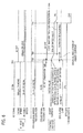
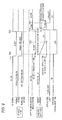
- Figs. 5 to 8 are timing charts showing the operations of the electric steering device 20 according to the invention.
- the timing chart of Fig. 5 shows a normal stop operation in which the ignition signal is switched off after the vehicle 10 stops.
- Fig. 5 shows, as information on the vehicle 10 side, ON/OFF of the ignition (IG) signal, an engine speed and a running speed.
- the ON/OFF of the ignition signal represents ON/OFF states of the ignition signal outputted from the ignition switch 104, respectively.
- An engine speed and a running speed represent information outputted from the vehicle ECU 102.
- Fig. 5 shows, as information on the EPS control unit 206 (control unit) side, a recognition state of a running speed, a recognition state of presence or absence of the ignition (IG) signal, an upper limit of supply current (assist current) to the electric actuator 208, a display state of the alarm lamp on the display unit 108 and an approval/disapproval of CAN communication in the EPS control unit 206.
- the recognition state of a running speed represents a running speed acquired by the speed acquisition unit 2066.
- the recognition state of presence or absence of the ignition signal represents a detection result of the ignition signal detection unit 2064.
- the upper limit of supply current (assist current) to the electric actuator 208 represents a supply current to the electric actuator 208 controlled by the output control unit 2068.
- the display state of the alarm lamp on the display unit 108 represents turned-on or off of the alarm lamp by the display control unit 2069.
- the approval/disapproval of the CAN communication in the EPS control unit 206 represents an activation state of the EPS control unit 206.
- the vehicle 10 is in a normal running state. That is, the ignition signal of the vehicle 10 side is in the ON state, an engine speed is 500rpm or more and a running speed is 2km/h or more. Further, the recognition state of a running speed in the EPS control unit 206 (control unit) is 2km/h or more, the recognition state of presence or absence of the ignition signal is ON (presence), the upper limit of supply current to the electric actuator 208 is a rated value (value in the normal assist control), the display state of the alarm lamp is turned-off and the CAN communication in the EPS control unit 206 is in an ON (approval) state.
- a running speed (predetermined speed), as a threshold value for determining whether or not the processing proceeds to the reduced assist control, is 2km/h.
- the recognition state of a running speed on the EPS control unit 206 side also becomes lower than 2km/h in linkage therewith.
- the ignition switch 104 is turned off at a time point TA2
- the ignition signal is switched off and hence the engine is stopped.
- the engine can be considered to be in a stopped state when an engine speed is 400rpm or less.
- the ignition signal detection unit 2064 recognizes, at a time point TA3 (time point TA2 + IG determination time) upon lapse of a predetermined determination time (IG determination time) after the ignition signal outputted from the ignition switch 104 is switched off, that the ignition signal is switched off.
- the assist termination processing is started. That is, a current supplied to the electric actuator 208 is reduced gradually after the time point TA3 and becomes 0A at a time point TA4. Further, the EPS control unit 206 switches the CAN communication in an OFF (disapproval) state at the time point TA3. As the CAN communication is in the OFF state, display control on the display unit 108 can also not be performed (dotted line in the drawing).
- the ignition switch 104 is turned on again at a time point TA5
- the ignition signal is switched on.
- the engine is started and an engine speed is increased to 500rpm or more.
- the recognition state of the ignition signal on the EPS control unit 206 side becomes ON at a time point TA6 upon lapse of the IG determination time after the time point TA5.
- a current supplied to the electric actuator 208 is increased gradually and reaches the rated value at a time point TA7.
- the EPS control unit 206 switches the CAN communication in the ON state.
- the display control unit 2069 switches the alarm lamp of the display unit 108 in the turned-on state for initial checking for a constant time (from the time point TA6 to a time point TA8).
- the vehicle 10 starts running and the normal assist control is performed.
- the timing chart of Fig. 6 shows an operation in a case that the ignition signal is switched off during running of the vehicle 10.
- the vehicle 10 is in the normal running state. That is, the ignition signal on the vehicle 10 side is in the ON state, an engine speed is 500rpm or more and a running speed is 2km/h or more. Further, the recognition state of a running speed in the EPS control unit 206 (control unit) is 2km/h or more, the recognition state of presence or absence of the ignition signal is ON, the upper limit of supply current to the electric actuator 208 is the rated value (value in the normal assist control), the display state of the alarm lamp is turned-off and the CAN communication in the EPS control unit 206 is in the ON state.
- a running speed is kept to be 2km/h or more.
- the reduced assist control is started. That is, a supply current to the electric actuator 208 is not set to 0A but is gradually reduced to a reduced assist control value (for example, 50% of the rated value) during a constant time until a time point TB3.
- a reduced assist control value for example, 50% of the rated value
- the display control unit 2069 switches the alarm lamp of the display unit 108 in the turned-on state or a flashing state at the time point TB2.
- the reduced assist control is terminated and then the assist termination processing is performed. That is, a supply current to the electric actuator 208 is gradually reduced to 0A during a constant time, and also the EPS control unit 206 switches the CAN communication in the OFF state. As the CAN communication is in the OFF state, display control on the display unit 108 can also not be performed (dotted line in the drawing).
- the timing chart of Fig. 7 shows an operation in a case that the ignition signal is switched on again after the ignition signal is switched off during running of the vehicle 10.
- the vehicle 10 is in the normal running state. That is, the ignition signal of the vehicle 10 side is in the ON state, an engine speed is 500rpm or more and a running speed is 2km/h or more. Further, the recognition state of a running speed in the EPS control unit 206 (control unit) is 2km/h or more, the recognition state of presence or absence of the ignition signal is ON, the upper limit of supply current to the electric actuator 208 is the rated value (value in the normal assist control), the display state of the alarm lamp is turned-off and the CAN communication in the EPS control unit 206 is in the ON state.
- the ignition switch 104 is turned off at a time point TC1, the ignition signal is switched off, and thus the engine is stopped (400rpm or less). In contrast, a running speed is kept to be 2km/h or more.
- the reduced assist control is started. That is, a supply current to the electric actuator 208 is not set to 0A but is gradually reduced to the reduced assist control value (for example, 50% of the rated value) during a constant time until a time point TC3.
- the display control unit 2069 switches the alarm lamp of the display unit 108 in the turned-on state or the flashing state at the time point TC2.
- the recognition state of the ignition signal on the EPS control unit 206 side becomes ON at a time point TC5 upon lapse of the IG determination time after the time point TC4.
- a current supplied to the electric actuator 208 is increased gradually and becomes the rated value at a time point TC6, thus the normal assist control is stared again
- the display control unit 2069 switches the alarm lamp of the display unit 108 in the turned-off state at the time point TC6.
- the timing chart of Fig. 8 shows an operation in a case that an interface (IG I/F) for detecting the ignition signal becomes failure during running of the vehicle 10.
- the failure of the interface for detecting the ignition signal is disconnection between the ignition switch 104 and the EPS control unit 206.
- the vehicle 10 is in the normal running state. That is, the ignition signal of the vehicle 10 side is in the ON state, an engine speed is 500rpm or more and a running speed is 2km/h or more.
- the recognition state of a running speed in the EPS control unit 206 is 2km/h or more
- the recognition state of presence or absence of the ignition signal is ON
- the upper limit of supply current to the electric actuator 208 is the rated value (value in the normal assist control)
- the display state of the alarm lamp is turned-off
- the CAN communication in the EPS control unit 206 is in the ON state.
- the normal running state an engine speed is 500rpm or more and a running speed is 2km/h or more
- the reduced assist control is started. That is, a supply current to the electric actuator 208 is not set to 0A but is gradually reduced to the reduced assist control value (for example, 50% of the rated value) during a constant time from the time point TD2 to a time point TD3.
- the display control unit 2069 switches the alarm lamp of the display unit 108 in the turned-on state or the flashing state at the time point TD2. Thereafter, when a predetermined time elapses (time point TD4) after starting the reduced assist control, the reduced assist control is terminated and then the assist termination processing is performed. That is, a supply current to the electric actuator 208 is gradually reduced to 0A during a constant time until a time point TD5, and also the EPS control unit 206 turns off the CAN communication at the time point TD4. As the CAN communication is in the OFF state, display control on the display unit 108 can also not be performed (dotted line in the drawing).
- Fig. 9 is a timing chart showing the operation of the electric steering device of the related art.
- Fig. 9 differs from the present invention (see Figs. 5 to 8 ) in a point that the EPS control unit 206 does not recognize a running speed.
- the vehicle 10 is in the normal running state. That is, the ignition signal on the vehicle 10 side is in the ON state, an engine speed is 500rpm or more and a running speed is 2km/h or more.
- the recognition state of presence or absence of the ignition signal in the EPS control unit 206 is ON, the upper limit of supply current to the electric actuator 208 is the rated value (value in the normal assist control), the display state of the alarm lamp is turned-off and the CAN communication in the EPS control unit 206 is in the ON state.
- the ignition switch 104 When the ignition switch 104 is turned off at a time point TE1, the ignition signal is switched off, and thus an engine speed reduces (400rpm or less). In contrast, a running speed is kept to be higher than 0km/h.
- the EPS control unit 206 side recognizes that the ignition signal is switched off at a time point TE2 (time point TE1 + iG determination time), the assist termination processing is started. That is, a current supplied to the electric actuator 208 is reduced gradually to 0A during a constant time until a time point TE3. Further, the EPS control unit 206 switches the CAN communication in the OFF state at the time point TE2. As the CAN communication is in the OFF state, display control on the display unit 108 can also not be performed (dotted line in the drawing). During this period, as a steering assist force is not generated at all, a large force is required for the steering operation.
- the ignition switch 104 is turned on again at a time point TE4, the ignition signal is switched on and thus the engine is started (500rpm or more).
- the recognition state of the ignition signal on the EPS control unit 206 side becomes ON at a time point TE5 (time point TE4 + IG determination time).
- the EPS control unit 206 switches the CAN communication in the ON state.
- a current supplied to the electric actuator 208 is increased gradually and becomes the rated value at a time point TE6.
- the display control unit 2069 switches the alarm lamp of the display unit 108 in the turned-on state for initial checking for a constant time (from the time point TE5 to a time point TE7).
- the electric steering device 20 reduces the upper limit of a steering assist force generated in the electric actuator than the case that the ignition signal is detected (normal assist control).
- the electric steering device 20 calculates a steering assist force in the reduced assist control by multiplying the upper limit of a steering assist force generated in the normal assist control by the correction coefficient smaller than 1.
- a steering assist force in the reduced assist control can be determined easily.
- the electric steering device 20 changes a steering assist force depending on a running speed, and also generates a steering assist force at each of the respective running speeds in the reduced assist control by multiplying a steering assist force generated at each of the respective running speeds by the correction coefficient.
- the electric steering device 20 reduces a steering assist force as a running speed becomes higher.
- straight running stability can be improved.
- the electric steering device 20 stops generation of a steering assist force.
- a driver can more easily notice a trouble (erroneous operation or failure) of the vehicle 10.
- a trouble erroneous operation or failure
Landscapes
- Engineering & Computer Science (AREA)
- Chemical & Material Sciences (AREA)
- Combustion & Propulsion (AREA)
- Transportation (AREA)
- Mechanical Engineering (AREA)
- Steering Control In Accordance With Driving Conditions (AREA)
- Power Steering Mechanism (AREA)
Abstract
Description
- The present invention relates to an electric steering device for assisting a steering operation of a vehicle.
- An electric steering device has been known which generates a steering assist force using an electric actuator for assisting a steering operation, that is, an operation of a steering wheel of a vehicle.
- As the electric steering device is driven by electric power, driving of the electric steering device is stopped when a power supply system of a vehicle is turned off. When driving of the electric steering device is stopped, as a driver performs a steering operation without a steering assist force, the steering operation is required to be performed with a larger force than usual.
- A patent literature 1 discloses a technique which includes a detection unit for detecting a turning-on/off of a power supply switch of a vehicle and a determination unit for determining whether or not a running speed of the vehicle is lower than a predetermined speed. In this technique, in a case that the detection unit detects the turning-off of the power supply switch, power supply to a steering device for the vehicle is stopped only when the determination unit determines that the running speed is lower than the predetermined speed.
[Patent Literature 1]JP-A-2000-128009 - In this related art, for example, even in a case that the power supply switch is erroneously turned off during running of the vehicle or the detection unit for detecting a state of the power supply switch becomes failure, it is possible to continuously drive the steering device for the vehicle to generate the steering assist force similar to that in the normal state. Thus, if the aforesaid erroneous operation, failure or the like occurs, it is possible to avoid occurrence of such a phenomenon that a steering wheel suddenly becomes heavy, that is, a force required for operating the steering wheel suddenly becomes large, during running of the vehicle and hence the steering operation becomes difficult.
- However, the aforesaid related art has a problem that the driver is hard to notice the erroneous operation or failure.
- Therefore, the invention, having been contrived bearing in mind the heretofore described circumstances, has for its object to provide an electric steering device which enables a driver to easily notice an erroneous operation with respect to a vehicle and a failure of a power supply system while maintaining steering performance of the vehicle.
- According to an embodiment of the present invention, there is provided an electric steering device comprising:
- an electric actuator which generates a steering assist force for a steering mechanism of a vehicle,
- a control unit which controls the steering assist force generated from the electric actuator based on a steering operation by a driver,
- an ignition signal detection unit which detects presence or absence of an ignition signal of the vehicle, and
- a speed acquisition unit which acquires a running speed of the vehicle,
- wherein, in a case that the ignition signal is not detected and the running speed is equal to or larger than a predetermined speed, the control unit reduces an upper limit of the steering assist force generated from the electric actuator so as to be smaller than an upper limit in a case that the ignition signal is detected.
- In the case that the ignition signal is not detected and the running speed is equal to or larger than the predetermined speed, the control unit may multiply the upper limit of the steering assist force generated in the case that the ignition signal is detected by a correction coefficient smaller than 1 so that the upper limit is reduced so as to be smaller than the upper limit in the case that the ignition signal is detected.
- The control unit may change the steering assist force depending on the running speed, and may multiply the steering assist force generated at each of the respective running speeds by the correction coefficient so that the steering assist force generated at each of the respective running speeds is reduced so as to be smaller than the upper limit in the case that the ignition signal is detected.
- The control unit may change the correction coefficient depending on the running speed.
- The higher the running speed is, the smaller the steering assist force may be set by the control unit.
- In a case that the ignition signal is not detected and the running speed is equal to or larger than the predetermined speed is continued for a predetermined time or more, the control unit may stop generation of the steering assist force by the electric actuator.
-
-
Fig. 1 is a block diagram showing configuration of anelectric steering device 20 according to an embodiment. -
Fig. 2 is a block diagram showing functional configuration of anEPS control unit 206. -
Fig. 3 is a graph showing a relation between a steering assist force and a running speed of avehicle 10 -
Fig. 4 is a flowchart showing a procedure of control processing of theelectric steering device 20 performed by theEPS control unit 206. -
Fig. 5 is a timing chart showing an operation of theelectric steering device 20 according to the invention. -
Fig. 6 is a timing chart showing an operation of theelectric steering device 20 according to the invention. -
Fig. 7 is a timing chart showing an operation of theelectric steering device 20 according to the invention. -
Fig. 8 is a timing chart showing an operation of theelectric steering device 20 according to the invention. -
Fig. 9 is a timing chart showing an operation of an electric steering device of a related art. - Hereinafter, an electric steering device according to an embodiment of the invention will be explained in detail with reference to accompanying drawings.
-
Fig. 1 is a block diagram showing configuration of anelectric steering device 20 according to the embodiment. - The
electric steering device 20 according to the embodiment is mounted in avehicle 10 and configured by including asteering wheel 202, atorque sensor 204, an EPS (Electric Power Steering)control unit 206 and anelectric actuator 208. - The
steering wheel 202 is provided at a driver's compartment and accepts a steering operation, that is, an operation of the steering wheel of a driver. - The
torque sensor 204 detects an amount of steering operation with respect to thesteering wheel 202 and outputs the detected amount as a torque value. - The
EPS control unit 206 is a microcomputer which is configured by including a CPU, an ROM for storing control program, and so on, an RAM acting as an operation area for the control program, an EEPROM for holding various kinds of data so as to be rewritable, an interface part acting as an interface with a peripheral circuit etc., and so on. The EPS control unit constitutes control means recited in claims. - The
EPS control unit 206 controls a steering assist force, generated by theelectric actuator 208 described later, based on a steering operation of a driver. - The
electric actuator 208 is driven by electric power stored in abattery 106 to generate a steering assist force applied to asteering mechanism 210 of a vehicle. Although various types are known as thesteering mechanism 210, the steering mechanism is configured by including tie rods, knuckle arms, a rack, a pinion gear, and so on and changes a direction of tires T. - The
vehicle 10 is configured by including a vehicle ECU 102, anignition switch 104, thebattery 106 and adisplay unit 108. - The vehicle ECU 102 is a microcomputer which is configured by including a CPU, an ROM for storing control program, and so on, an RAM acting as an operation area for the control program, an EEPROM for holding various kinds of data so as to be rewritable, an interface part acting as an interface with a peripheral circuit etc., and so on. The vehicle ECU controls entirety of the
vehicle 10. - In this embodiment, the vehicle ECU 102 outputs data representing a running speed of the
vehicle 10 to theEPS control unit 206. - The
ignition switch 104 detects an operation of an engine key by a driver and outputs a signal representing the detection result. In general, theignition switch 104 detects four kinds of operation states, that is, "OFF", "ACC", "ON" and "START". "OFF" represents a state that the engine key is detachable from a key cylinder and theignition switch 104 has not been operated yet. "ACC" represents a state that an engine has not been started yet but electric power is supplied to a part of electric equipments (a car navigation equipment, a vehicle air conditioner, and so on) within thevehicle 10. "ON" represents a state that after the engine key is once operated to a "START" position to start the engine, the engine key is stayed at this position. Thus, in this state, the engine is driven and electric power is supplied to all the electric equipments within thevehicle 10. - An ignition signal described later is a signal outputted from the
ignition switch 104 in a case that the engine key locates at an "ON" position. - The electric steering device 20 (in particular, the electric actuator 208) is usually operated when the
ignition switch 104 is in the "ON" state, that is, when the ignition signal in an ON state is outputted. - Incidentally, in this embodiment, explanation is made that a start operation of the
vehicle 10 is performed by operating the engine key. However, in a case that the start operation of thevehicle 10 is performed by operating a start switch, an IG (ignition) signal is outputted from an OSS (One-touch Start System) ECU in place of theignition switch 104. - The
battery 106 stores power for driving the electric equipments within thevehicle 10. Theelectric actuator 208 is one of the electric equipments driven by electric power supplied from thebattery 106. Specifically, electric power stored in thebattery 106 is supplied to theelectric actuator 208 via theEPS control unit 206. TheEPS control unit 206 controls a current supplied to theelectric actuator 208, thereby controlling an output of theelectric actuator 208. - Power stored in the
battery 106 is also supplied to the vehicle ECU 102, thedisplay unit 108, theEPS control unit 206, and so on so as to drive them. Wirings to these electric equipments are omitted in the drawing. - The
display unit 108 is provided in the vicinity of a dashboard of the driver's compartment and displays various kinds of information with respect to a driver. In this embodiment, thedisplay unit 108 displays at least information (an alarm lamp, for example) representing a failure of theelectric steering device 20. -
Fig. 2 is a block diagram showing functional configuration of theEPS control unit 206. - The
EPS control unit 206 realizes a torqueinformation acquisition unit 2062, an ignitionsignal detection unit 2064, aspeed acquisition unit 2066, anoutput control unit 2068 and adisplay control unit 2069, when the CPU executes the control program. - The torque
information acquisition unit 2062 acquires a torque value representing an amount of steering operation outputted from thetorque sensor 204. - The ignition
signal detection unit 2064 detects presence or absence (ON or OFF) of the ignition signal of thevehicle 10 outputted from theignition switch 104. - The
speed acquisition unit 2066 acquires data representing a running speed of thevehicle 10 outputted from thevehicle ECU 102. A running speed of thevehicle 10 may be acquired from, for example, an ABS (Antilock Brake System) as well as thevehicle ECU 102. This is because, in a case of thevehicle 10 mounting the ABS thereon, a running speed acquired from the ABS is closer to an actual value than a running speed acquired from thevehicle ECU 102. - The
output control unit 2068 determines a steering assist force based on a torque value acquired by the torqueinformation acquisition unit 2062 and controls a driving direction, a driving speed, and so on of theelectric actuator 208. - In a case that the ignition signal of the
vehicle 10 is not detected and a running speed of thevehicle 10 is a predetermined speed or more, theoutput control unit 2068 reduces an upper limit of a steering assist force generated from theelectric actuator 208 so as to be smaller than an upper limit in a case that the ignition signal is detected. - As described above, usually, the
electric steering device 20 operates when the ignition signal is in the ON state, that is, the ignition signal is detected. Thus, for example, during running of thevehicle 10, if the ignition signal is interrupted by erroneously shifting the engine key to an "OFF" or "ACC" position or erroneously pushing the start switch, the operation of theelectric steering device 20 is stopped. As a result, suddenly the steering wheel may become heavy or the steering operation may become difficult. Further, for example, during running of thevehicle 10, if a wiring between theignition switch 104 and theEPS control unit 206 is damaged and hence theEPS control unit 206 cannot detect the ignition signal, if the ignition switch 104 (or the vehicle ECU 102) becomes failure, or if an ignition recognition circuit of theEPS control unit 206 becomes failure, the operation of theelectric steering device 20 is also stopped. - On the other hand, if the
electric steering device 20 is driven like the normal state in a situation that the ignition signal cannot be detected, a driver may not be able to notice a trouble (the aforesaid erroneous operation or failure) of thevehicle 10. Thus, another trouble such as battery exhaustion may further occur. - In view of this, in the
electric steering device 20 according to the invention, even if the ignition signal is not detected during running of the vehicle 10 (running speed is equal to or higher than the predetermined speed), theelectric actuator 208 is continuously driven. Further, the upper limit of a steering assist force being generated is reduced so as to be smaller than the case that the ignition signal is detected. As a result, a driver can easily notice the trouble of thevehicle 10. - In this manner, in a case of continuously driving the
electric actuator 208 in a situation that the ignition signal cannot be detected, thedisplay control unit 2069 displays the alarm lamp or the like on thedisplay unit 108 so that a driver can more easily notice the trouble. -
Fig. 3 is a graph showing a relation between a steering assist force and a running speed of thevehicle 10. - In
Fig. 3 , an ordinate shows a current value (ampere) supplied to theelectric actuator 208, as a value representing a steering assist force. An abscissa shows a running speed (km/h) of thevehicle 10. - A steady line shows a steering assist force in a state of normal assist control (in a case that the ignition signal is detected). A dotted line shows a steering assist force in a case that the ignition signal of the
vehicle 10 is not detected and a running speed of thevehicle 10 is the predetermined speed or more. - The control "in the case that the ignition signal of the
vehicle 10 is not detected and a running speed of thevehicle 10 is the predetermined speed or more" shown by the dotted line is called "reduced assist control" because a steering assist force is reduced than the case of the normal assist control. - The running speed (predetermined speed) as a threshold value, for determining whether or not the assist control shifts to the reduced assist control, is shown by Vx in the abscissa of
Fig. 3 . Thus, in the curved dotted line representing the reduced assist control, actually a steering assist force is not generated on the left side than Vx (0km/h side). However, the dotted line is shown on the left side than Vx merely for convenience of explanation. - As shown in
Fig. 3 , theoutput control unit 2068 changes a steering assist force depending on a running speed of thevehicle 10. - Specifically, a steering assist force is made maximum in a low running speed range near 0km/h. Further, the higher a running speed is, the smaller a steering assist force is made. Thus, the upper limit of a steering assist force is a steering assist force at a running speed near 0km/h.
- In the case that the ignition signal is not detected and a running speed is the predetermined speed or more, the
output control unit 2068 multiplies the upper limit of a steering assist force, generated in the case that the ignition signal is detected, by a correction coefficient smaller than 1. By doing so, the upper limit is reduced than the case that the ignition signal is detected (in the case of normal assist control). - In the example shown in
Fig. 3 , although the upper limit of a steering assist force is 80A, this value is multiplied by the correction coefficient of 0.5 (< 1) and reduced to 40A. The correction coefficient is not limited to 0.5 but may be any value in a range larger than 0 and smaller than 1. - As a result, a driver feels that the steering wheel is heavy, that is, a force required for operating the steering wheel is larger than the case of normal assist control. Thus, a driver can easily notice that any troubles occurs in the
vehicle 10 due to a sense of incongruity. - As shown in
Fig. 3 , theoutput control unit 2068 changes a steering assist force depending on a running speed. Simultaneously, the output control unit multiplies a steering assist force generated at each of respective running speeds by the correction coefficient, thereby reducing the steering assist force generated at each of the respective running speeds than the case that the ignition signal is detected (in the case of normal assist control). - In the example shown in
Fig. 3 , as a steering assist force at each of the respective running speeds is multiplied by the correction coefficient of 0.5, the steering assist force is suppressed to 50% as a whole as compared with the case of normal assist control. - In this manner, as a steering assist force at each of the respective running speeds is multiplied by the uniform correction coefficient, it becomes possible to prevent occurrence of such a phenomenon that, when a running speed changes, a steering assist force changes excessively to impair steering stability.
- The correction coefficient, by which a steering assist force at each of the respective running speeds is multiplied, may not be uniform. For example, the correction coefficient may be changed depending on a running speed. As an example, the higher a running speed is, the larger the correction coefficient may be made. Alternatively, the lower a running speed is, the smaller the correction coefficient may be made. As another example, the larger an amount of deviation of a running speed from the current running speed of the
vehicle 10 is, the larger (or smaller) the correction coefficient may be made. - As still another example, a steering assist force in a state of the reduced assist control may be determined by subtracting a constant value uniformly, from the steering assist force in a state of the normal assist control, at each of the respective running speeds.
- Such the reduced assist control may be terminated, for example, after continuing this control for a predetermined time, thus stopping generation of a steering assist force.
- That is, if a situation that the ignition signal is not detected and a running speed is the predetermined speed or more is continued for a predetermined time or more, the
output control unit 2068 may control theelectric actuator 208 to stop generation of a steering assist force. - This is because, in a case that a driver continues a driving without noticing a trouble of the
vehicle 10 even in the state of the reduced assist control, the driver can more likely notice the trouble of thevehicle 10 by making the steering wheel heavier. - Further, for example, if a running speed acquired from the
vehicle ECU 102 is erroneous, the reduced assist control may be continued despite that thevehicle 10 is stopped actually. If such a situation continues, a charged amount of thebattery 106 may reduce and then battery exhaustion may occur. In order to avoid such a phenomenon, the reduced assist control may be terminated after continuing this control for the predetermined time. -
Fig. 4 is a flowchart showing a procedure of control processing of theelectric steering device 20 performed by theEPS control unit 206. - In the flowchart shown in
Fig. 4 , firstly theEPS control unit 206 determines whether or not the ignition (IG) signal of thevehicle 10 is detected (ON) (step S400) and whether or not the engine is started (step S402). - When the ignition signal is not detected (No in step S400) or the engine is not started (No in step S402), the processing is placed in a standby mode.
- When the ignition signal is detected (Yes in step S400) and the engine is started (Yes in step S402), the normal assist control shown in
Fig. 3 is performed (step S404). - After starting the normal assist control in step S404, the
EPS control unit 206 always determines whether or not the ignition signal is detected (step S406). While the ignition signal is detected (No in step S406), the processing returns to step S404 and the normal assist control is continued. - In contrast, when the ignition signal is not detected (OFF) (Yes in step S406), the
EPS control unit 206 determines whether or not a current running speed of thevehicle 10 is the predetermined speed or more (step S408). When the running speed of thevehicle 10 is not the predetermined speed or more (No in step S408), it is determined that thevehicle 10 is stopped and an assist termination processing is performed (step S418). Thus, the processing of this flowchart is terminated. - The assist termination processing includes gradual reduction of a steering assist force generated by the
electric actuator 208, stop of driving of theelectric actuator 208, a storing processing of various kinds of settings, and so on. - In contrast, when the running speed of the
vehicle 10 in step S408 is the predetermined speed or more (Yes in step S408), the reduced assist control is performed as shown by the dotted line inFig. 3 (step S410). - After starting the reduced assist control in step S410, the
EPS control unit 206 determines whether or not the ignition signal is detected (ON) again (step S412). When the ignition signal is detected again (Yes in step S412), the processing returns to step S404 and the normal assist control is performed. - When a running speed of the
vehicle 10 reduces lower than the predetermined speed during the reduced assist control (No in step S414), it is determined that thevehicle 10 is stopped and then the assist termination processing is performed (step S418). Thus, the processing of this flowchart is terminated. - Until the predetermined time elapses after starting the reduced assist control (No in step S416), the
EPS control unit 206 returns the processing to step S410 and continues the reduced assist control. Then, when the predetermined time elapses after starting the reduced assist control (Yes in step S416), the assist termination processing is performed (step S418). Thus, the processing of this flowchart is terminated. - More detail operations of the
electric steering device 20 will be explained with reference to timing charts. -
Figs. 5 to 8 are timing charts showing the operations of theelectric steering device 20 according to the invention. - The timing chart of
Fig. 5 shows a normal stop operation in which the ignition signal is switched off after thevehicle 10 stops. -
Fig. 5 shows, as information on thevehicle 10 side, ON/OFF of the ignition (IG) signal, an engine speed and a running speed. The ON/OFF of the ignition signal represents ON/OFF states of the ignition signal outputted from theignition switch 104, respectively. An engine speed and a running speed represent information outputted from thevehicle ECU 102. - Further,
Fig. 5 shows, as information on the EPS control unit 206 (control unit) side, a recognition state of a running speed, a recognition state of presence or absence of the ignition (IG) signal, an upper limit of supply current (assist current) to theelectric actuator 208, a display state of the alarm lamp on thedisplay unit 108 and an approval/disapproval of CAN communication in theEPS control unit 206. The recognition state of a running speed represents a running speed acquired by thespeed acquisition unit 2066. The recognition state of presence or absence of the ignition signal represents a detection result of the ignitionsignal detection unit 2064. The upper limit of supply current (assist current) to theelectric actuator 208 represents a supply current to theelectric actuator 208 controlled by theoutput control unit 2068. The display state of the alarm lamp on thedisplay unit 108 represents turned-on or off of the alarm lamp by thedisplay control unit 2069. The approval/disapproval of the CAN communication in theEPS control unit 206 represents an activation state of theEPS control unit 206. - In an initial situation shown in
Fig. 5 , thevehicle 10 is in a normal running state. That is, the ignition signal of thevehicle 10 side is in the ON state, an engine speed is 500rpm or more and a running speed is 2km/h or more. Further, the recognition state of a running speed in the EPS control unit 206 (control unit) is 2km/h or more, the recognition state of presence or absence of the ignition signal is ON (presence), the upper limit of supply current to theelectric actuator 208 is a rated value (value in the normal assist control), the display state of the alarm lamp is turned-off and the CAN communication in theEPS control unit 206 is in an ON (approval) state. - In the following explanation, a running speed (predetermined speed), as a threshold value for determining whether or not the processing proceeds to the reduced assist control, is 2km/h.
- When a running speed recognized on the
vehicle 10 side becomes lower than 2km/h at a time point TA1, the recognition state of a running speed on theEPS control unit 206 side also becomes lower than 2km/h in linkage therewith. Thereafter, when theignition switch 104 is turned off at a time point TA2, the ignition signal is switched off and hence the engine is stopped. In this respect, the engine can be considered to be in a stopped state when an engine speed is 400rpm or less. - The ignition
signal detection unit 2064 recognizes, at a time point TA3 (time point TA2 + IG determination time) upon lapse of a predetermined determination time (IG determination time) after the ignition signal outputted from theignition switch 104 is switched off, that the ignition signal is switched off. - In this case, as the recognition state of a running speed on the
EPS control unit 206 side also becomes lower than 2km/h, the assist termination processing is started. That is, a current supplied to theelectric actuator 208 is reduced gradually after the time point TA3 and becomes 0A at a time point TA4. Further, theEPS control unit 206 switches the CAN communication in an OFF (disapproval) state at the time point TA3. As the CAN communication is in the OFF state, display control on thedisplay unit 108 can also not be performed (dotted line in the drawing). - Thereafter, when the
ignition switch 104 is turned on again at a time point TA5, the ignition signal is switched on. Thus, the engine is started and an engine speed is increased to 500rpm or more.
The recognition state of the ignition signal on theEPS control unit 206 side becomes ON at a time point TA6 upon lapse of the IG determination time after the time point TA5. In linkage with this, a current supplied to theelectric actuator 208 is increased gradually and reaches the rated value at a time point TA7. Further, theEPS control unit 206 switches the CAN communication in the ON state. Thedisplay control unit 2069 switches the alarm lamp of thedisplay unit 108 in the turned-on state for initial checking for a constant time (from the time point TA6 to a time point TA8).
Thereafter, thevehicle 10 starts running and the normal assist control is performed. The timing chart ofFig. 6 shows an operation in a case that the ignition signal is switched off during running of thevehicle 10. - Also in the initial situation shown in
Fig. 6 , thevehicle 10 is in the normal running state. That is, the ignition signal on thevehicle 10 side is in the ON state, an engine speed is 500rpm or more and a running speed is 2km/h or more. Further, the recognition state of a running speed in the EPS control unit 206 (control unit) is 2km/h or more, the recognition state of presence or absence of the ignition signal is ON, the upper limit of supply current to theelectric actuator 208 is the rated value (value in the normal assist control), the display state of the alarm lamp is turned-off and the CAN communication in theEPS control unit 206 is in the ON state. - When the
ignition switch 104 is turned off at a time point TB1, the ignition signal is switched off, and thus the engine is also stopped (400rpm or less). In contrast, a running speed is kept to be 2km/h or more. - Although it is recognized on the
EPS control unit 206 side at a time point TB2 that the ignition signal is switched off, as the recognition state of a running speed is 2km/h or more, the reduced assist control is started. That is, a supply current to theelectric actuator 208 is not set to 0A but is gradually reduced to a reduced assist control value (for example, 50% of the rated value) during a constant time until a time point TB3. - The
display control unit 2069 switches the alarm lamp of thedisplay unit 108 in the turned-on state or a flashing state at the time point TB2. - Thereafter, when a predetermined time elapses after starting the reduced assist control (time point TB4), the reduced assist control is terminated and then the assist termination processing is performed. That is, a supply current to the
electric actuator 208 is gradually reduced to 0A during a constant time, and also theEPS control unit 206 switches the CAN communication in the OFF state. As the CAN communication is in the OFF state, display control on thedisplay unit 108 can also not be performed (dotted line in the drawing).
The timing chart ofFig. 7 shows an operation in a case that the ignition signal is switched on again after the ignition signal is switched off during running of thevehicle 10. - Also in the initial situation shown in
Fig. 7 , thevehicle 10 is in the normal running state. That is, the ignition signal of thevehicle 10 side is in the ON state, an engine speed is 500rpm or more and a running speed is 2km/h or more. Further, the recognition state of a running speed in the EPS control unit 206 (control unit) is 2km/h or more, the recognition state of presence or absence of the ignition signal is ON, the upper limit of supply current to theelectric actuator 208 is the rated value (value in the normal assist control), the display state of the alarm lamp is turned-off and the CAN communication in theEPS control unit 206 is in the ON state.
When theignition switch 104 is turned off at a time point TC1, the ignition signal is switched off, and thus the engine is stopped (400rpm or less). In contrast, a running speed is kept to be 2km/h or more. - Although it is recognized on the
EPS control unit 206 side at a time point TC2 that the ignition signal is switched off, as the recognition state of a running speed is 2km/h or more, the reduced assist control is started. That is, a supply current to theelectric actuator 208 is not set to 0A but is gradually reduced to the reduced assist control value (for example, 50% of the rated value) during a constant time until a time point TC3. - The
display control unit 2069 switches the alarm lamp of thedisplay unit 108 in the turned-on state or the flashing state at the time point TC2. - Thereafter, when the
ignition switch 104 is turned on again at a time point TC4, the ignition signal on thevehicle 10 side is switched on and the engine is started (500rpm or more). - The recognition state of the ignition signal on the
EPS control unit 206 side becomes ON at a time point TC5 upon lapse of the IG determination time after the time point TC4. In linkage with this, a current supplied to theelectric actuator 208 is increased gradually and becomes the rated value at a time point TC6, thus the normal assist control is stared again - Further, the
display control unit 2069 switches the alarm lamp of thedisplay unit 108 in the turned-off state at the time point TC6.
The timing chart ofFig. 8 shows an operation in a case that an interface (IG I/F) for detecting the ignition signal becomes failure during running of thevehicle 10.
For example, the failure of the interface for detecting the ignition signal is disconnection between theignition switch 104 and theEPS control unit 206.
Also in the initial situation shown inFig. 8 , thevehicle 10 is in the normal running state. That is, the ignition signal of thevehicle 10 side is in the ON state, an engine speed is 500rpm or more and a running speed is 2km/h or more. Further, the recognition state of a running speed in the EPS control unit 206 (control unit) is 2km/h or more, the recognition state of presence or absence of the ignition signal is ON, the upper limit of supply current to theelectric actuator 208 is the rated value (value in the normal assist control), the display state of the alarm lamp is turned-off and the CAN communication in theEPS control unit 206 is in the ON state.
When the interface for detecting the ignition signal becomes failure at a time point TD1, theEPS control unit 206 recognizes at a time point TD2 after the IG determination time that the ignition signal is switched off. At this time, as the ignition signal on thevehicle 10 side is kept in the ON state, the normal running state (an engine speed is 500rpm or more and a running speed is 2km/h or more) is continued.
As the recognition state of a running speed in theEPS control unit 206 is 2km/h or more, the reduced assist control is started. That is, a supply current to theelectric actuator 208 is not set to 0A but is gradually reduced to the reduced assist control value (for example, 50% of the rated value) during a constant time from the time point TD2 to a time point TD3. - The
display control unit 2069 switches the alarm lamp of thedisplay unit 108 in the turned-on state or the flashing state at the time point TD2.
Thereafter, when a predetermined time elapses (time point TD4) after starting the reduced assist control, the reduced assist control is terminated and then the assist termination processing is performed. That is, a supply current to theelectric actuator 208 is gradually reduced to 0A during a constant time until a time point TD5, and also theEPS control unit 206 turns off the CAN communication at the time point TD4. As the CAN communication is in the OFF state, display control on thedisplay unit 108 can also not be performed (dotted line in the drawing).
Next, an operation of an electric steering device of a related art will be explained for the sake of comparison with theelectric steering device 20 according to the invention.
Fig. 9 is a timing chart showing the operation of the electric steering device of the related art.
Fig. 9 differs from the present invention (seeFigs. 5 to 8 ) in a point that theEPS control unit 206 does not recognize a running speed.
Also in the initial situation shown inFig. 9 , thevehicle 10 is in the normal running state. That is, the ignition signal on thevehicle 10 side is in the ON state, an engine speed is 500rpm or more and a running speed is 2km/h or more. Further, the recognition state of presence or absence of the ignition signal in the EPS control unit 206 (control unit) is ON, the upper limit of supply current to theelectric actuator 208 is the rated value (value in the normal assist control), the display state of the alarm lamp is turned-off and the CAN communication in theEPS control unit 206 is in the ON state. - When the
ignition switch 104 is turned off at a time point TE1, the ignition signal is switched off, and thus an engine speed reduces (400rpm or less). In contrast, a running speed is kept to be higher than 0km/h.
When theEPS control unit 206 side recognizes that the ignition signal is switched off at a time point TE2 (time point TE1 + iG determination time), the assist termination processing is started. That is, a current supplied to theelectric actuator 208 is reduced gradually to 0A during a constant time until a time point TE3. Further, theEPS control unit 206 switches the CAN communication in the OFF state at the time point TE2. As the CAN communication is in the OFF state, display control on thedisplay unit 108 can also not be performed (dotted line in the drawing).
During this period, as a steering assist force is not generated at all, a large force is required for the steering operation. - Thereafter, when the
ignition switch 104 is turned on again at a time point TE4, the ignition signal is switched on and thus the engine is started (500rpm or more).
The recognition state of the ignition signal on theEPS control unit 206 side becomes ON at a time point TE5 (time point TE4 + IG determination time). In linkage with this, theEPS control unit 206 switches the CAN communication in the ON state. Further, a current supplied to theelectric actuator 208 is increased gradually and becomes the rated value at a time point TE6. Thus, the normal assist control is started again.
Further, thedisplay control unit 2069 switches the alarm lamp of thedisplay unit 108 in the turned-on state for initial checking for a constant time (from the time point TE5 to a time point TE7). - As described above, in a case that the ignition signal of the
vehicle 10 is not detected and a running speed of thevehicle 10 is the predetermined speed or more, that is, in a case that the ignition signal is most probably switched off against an intension of a diver during running of thevehicle 10, theelectric steering device 20 according to the embodiment reduces the upper limit of a steering assist force generated in the electric actuator than the case that the ignition signal is detected (normal assist control). - By doing so, it is possible to avoid occurrence of such a phenomenon that the driving of the
electric steering device 20 is stopped completely and hence the steering operation becomes difficult. Further, as a steering assist force becomes smaller than the case of the normal assist control, a driver can easily notice a trouble (erroneous operation or failure) of the vehicle. - The
electric steering device 20 calculates a steering assist force in the reduced assist control by multiplying the upper limit of a steering assist force generated in the normal assist control by the correction coefficient smaller than 1. Thus, for example, even in a case that the upper limit of a steering assist force changes depending on the running state, a steering assist force in the reduced assist control can be determined easily. - Further, the
electric steering device 20 changes a steering assist force depending on a running speed, and also generates a steering assist force at each of the respective running speeds in the reduced assist control by multiplying a steering assist force generated at each of the respective running speeds by the correction coefficient. Thus, it becomes possible to prevent occurrence of such a phenomenon that, when a running speed changes, a steering assist force changes excessively to impair steering stability. - Further, the
electric steering device 20 reduces a steering assist force as a running speed becomes higher. Thus, as the steering wheel becomes heavier at a high speed running, straight running stability can be improved. - Further, if a situation that the ignition signal is not detected and a running speed is the predetermined speed or more is continued for a predetermined time or more, the
electric steering device 20 stops generation of a steering assist force. Thus, a driver can more easily notice a trouble (erroneous operation or failure) of thevehicle 10. Further, for example, even in a case that an acquired running speed is erroneous and the vehicle 10 (engine) is stopped actually, it is possible to avoid occurrence of such a phenomenon that a charged amount of thebattery 106 reduces and then battery exhaustion occurs.
Claims (6)
- An electric steering device comprising:an electric actuator which generates a steering assist force for a steering mechanism of a vehicle,a control unit which controls the steering assist force generated from the electric actuator based on a steering operation by a driver,an ignition signal detection unit which detects presence or absence of an ignition signal of the vehicle, anda speed acquisition unit which acquires a running speed of the vehicle, wherein, in a case that the ignition signal is not detected and the running speed is equal to or larger than a predetermined speed, the control unit reduces an upper limit of the steering assist force generated from the electric actuator so as to be smaller than an upper limit in a case that the ignition signal is detected.
- The electric steering device according to Claim 1, wherein
in the case that the ignition signal is not detected and the running speed is equal to or larger than the predetermined speed, the control unit multiplies the upper limit of the steering assist force generated in the case that the ignition signal is detected by a correction coefficient smaller than 1 so that the upper limit is reduced so as to be smaller than the upper limit in the case that the ignition signal is detected. - The electric steering device according to Claim 2, wherein
the control unit changes the steering assist force depending on the running speed, and multiplies the steering assist force generated at each of the respective running speeds by the correction coefficient so that the steering assist force generated at each of the respective running speeds is reduced so as to be smaller than the upper limit in the case that the ignition signal is detected. - The electric steering device according to Claim 3, wherein
the control unit changes the correction coefficient depending on the running speed. - The electric steering device according to Claim 4, wherein
the higher the running speed is, the smaller the steering assist force is set by the control unit. - The electric steering device according to any one of Claims 1 to 5, wherein
in a case that the ignition signal is not detected and the running speed is equal to or larger than the predetermined speed is continued for a predetermined time or more, the control unit stops generation of the steering assist force by the electric actuator.
Applications Claiming Priority (1)
| Application Number | Priority Date | Filing Date | Title |
|---|---|---|---|
| JP2014205504A JP6451192B2 (en) | 2014-10-06 | 2014-10-06 | Electric steering device |
Publications (2)
| Publication Number | Publication Date |
|---|---|
| EP3006307A1 true EP3006307A1 (en) | 2016-04-13 |
| EP3006307B1 EP3006307B1 (en) | 2020-03-11 |
Family
ID=54292591
Family Applications (1)
| Application Number | Title | Priority Date | Filing Date |
|---|---|---|---|
| EP15188250.3A Active EP3006307B1 (en) | 2014-10-06 | 2015-10-02 | Electric steering device |
Country Status (4)
| Country | Link |
|---|---|
| US (1) | US9796408B2 (en) |
| EP (1) | EP3006307B1 (en) |
| JP (1) | JP6451192B2 (en) |
| CN (1) | CN105480297B (en) |
Cited By (1)
| Publication number | Priority date | Publication date | Assignee | Title |
|---|---|---|---|---|
| WO2021213619A1 (en) * | 2020-04-20 | 2021-10-28 | Thyssenkrupp Presta Ag | Power saving mode for steering systems of a motor vehicle |
Families Citing this family (7)
| Publication number | Priority date | Publication date | Assignee | Title |
|---|---|---|---|---|
| JP6756302B2 (en) * | 2017-05-09 | 2020-09-16 | トヨタ自動車株式会社 | Vehicle control device |
| CN108073554B (en) * | 2018-01-05 | 2021-04-02 | 聊城大学 | Design method of assist characteristic curve of automobile electric power steering system based on SOC |
| JP7279657B2 (en) * | 2020-02-11 | 2023-05-23 | トヨタ自動車株式会社 | steering device |
| SE544553C2 (en) | 2020-06-23 | 2022-07-12 | Scania Cv Ab | Management of electrically assisted steering of a vehicle |
| PL4029727T3 (en) | 2021-01-13 | 2024-10-28 | Joseph Vögele AG | Construction machine with seat console |
| JP7684126B2 (en) * | 2021-07-21 | 2025-05-27 | 株式会社ジェイテクト | Steering gear |
| EP4166422B1 (en) * | 2021-10-15 | 2025-11-05 | Jtekt Corporation | Control device for vehicle |
Citations (6)
| Publication number | Priority date | Publication date | Assignee | Title |
|---|---|---|---|---|
| EP0805095A2 (en) * | 1996-04-30 | 1997-11-05 | Mitsubishi Denki Kabushiki Kaisha | Control apparatus for motor-driven power steering system of motor vehicle |
| US6032091A (en) * | 1997-07-24 | 2000-02-29 | Honda Giken Kogyo Kabushiki Kaisha | Electric power steering apparatus |
| EP1072498A2 (en) * | 1999-07-26 | 2001-01-31 | Koyo Seiko Co., Ltd. | Electric power steering system |
| US6223852B1 (en) * | 1997-08-18 | 2001-05-01 | Honda Giken Kogyo Kabushiki Kaisha | Electric power steering apparatus |
| DE102013018070A1 (en) * | 2012-11-30 | 2014-06-05 | Mando Corporation | Method for controlling stopping of motor-driven type power steering apparatus mounted in vehicle, involves delaying stopping of motor-driven power steering apparatus for predetermined time depending on confirmation result |
| US20150203152A1 (en) * | 2014-01-21 | 2015-07-23 | Honda Motor Co., Ltd. | Vehicle steering device |
Family Cites Families (17)
| Publication number | Priority date | Publication date | Assignee | Title |
|---|---|---|---|---|
| JP2583468Y2 (en) * | 1991-09-13 | 1998-10-22 | 光洋精工株式会社 | Power steering device |
| JP3345804B2 (en) | 1998-10-23 | 2002-11-18 | 光洋精工株式会社 | Vehicle steering system |
| JP3412580B2 (en) * | 1999-10-25 | 2003-06-03 | トヨタ自動車株式会社 | Electric power steering device for vehicles |
| JP3700547B2 (en) * | 2000-06-29 | 2005-09-28 | 三菱電機株式会社 | Electric power steering device |
| US6857496B2 (en) * | 2002-09-03 | 2005-02-22 | Trw Inc. | Vehicle steering apparatus with anti-steer security device |
| US7233850B2 (en) * | 2002-10-31 | 2007-06-19 | Koyo Seiko Co., Ltd. | Vehicle steering apparatus |
| JP2005348583A (en) * | 2004-06-07 | 2005-12-15 | Fuji Heavy Ind Ltd | Control device for electric vehicle |
| US7500537B2 (en) * | 2004-08-25 | 2009-03-10 | Toyota Jidosha Kabushiki Kaisha | Steering apparatus for vehicle |
| CN2803861Y (en) * | 2005-05-11 | 2006-08-09 | 中国第一汽车集团公司 | Electric boosting steering system |
| US8950520B2 (en) * | 2006-07-07 | 2015-02-10 | Hydro-Gear Limited Partnership | Front steering module for a zero turn radius vehicle |
| JP5444992B2 (en) * | 2009-09-24 | 2014-03-19 | 株式会社ジェイテクト | Electric power steering device |
| JP2012166746A (en) * | 2011-02-16 | 2012-09-06 | Jtekt Corp | Electric power steering system |
| JP6024656B2 (en) * | 2011-06-15 | 2016-11-16 | 株式会社ジェイテクト | Electric power steering device |
| CN102530059B8 (en) * | 2011-12-25 | 2018-09-07 | 东方久乐汽车安全气囊有限公司 | Electric boosting steering system |
| JP5811081B2 (en) * | 2012-12-18 | 2015-11-11 | 日本精工株式会社 | Power relay control device |
| JP5856109B2 (en) * | 2013-07-16 | 2016-02-09 | 本田技研工業株式会社 | Vehicle steering system |
| US9409595B2 (en) * | 2014-09-15 | 2016-08-09 | Steering Solutions Ip Holding Corporation | Providing assist torque without hand wheel torque sensor for zero to low vehicle speeds |
-
2014
- 2014-10-06 JP JP2014205504A patent/JP6451192B2/en active Active
-
2015
- 2015-10-02 EP EP15188250.3A patent/EP3006307B1/en active Active
- 2015-10-05 US US14/875,283 patent/US9796408B2/en active Active
- 2015-10-08 CN CN201510646715.9A patent/CN105480297B/en active Active
Patent Citations (6)
| Publication number | Priority date | Publication date | Assignee | Title |
|---|---|---|---|---|
| EP0805095A2 (en) * | 1996-04-30 | 1997-11-05 | Mitsubishi Denki Kabushiki Kaisha | Control apparatus for motor-driven power steering system of motor vehicle |
| US6032091A (en) * | 1997-07-24 | 2000-02-29 | Honda Giken Kogyo Kabushiki Kaisha | Electric power steering apparatus |
| US6223852B1 (en) * | 1997-08-18 | 2001-05-01 | Honda Giken Kogyo Kabushiki Kaisha | Electric power steering apparatus |
| EP1072498A2 (en) * | 1999-07-26 | 2001-01-31 | Koyo Seiko Co., Ltd. | Electric power steering system |
| DE102013018070A1 (en) * | 2012-11-30 | 2014-06-05 | Mando Corporation | Method for controlling stopping of motor-driven type power steering apparatus mounted in vehicle, involves delaying stopping of motor-driven power steering apparatus for predetermined time depending on confirmation result |
| US20150203152A1 (en) * | 2014-01-21 | 2015-07-23 | Honda Motor Co., Ltd. | Vehicle steering device |
Cited By (2)
| Publication number | Priority date | Publication date | Assignee | Title |
|---|---|---|---|---|
| WO2021213619A1 (en) * | 2020-04-20 | 2021-10-28 | Thyssenkrupp Presta Ag | Power saving mode for steering systems of a motor vehicle |
| US12509141B2 (en) | 2020-04-20 | 2025-12-30 | Thyssenkrupp Presta Ag | Power saving mode for steering systems of a motor vehicle |
Also Published As
| Publication number | Publication date |
|---|---|
| CN105480297A (en) | 2016-04-13 |
| CN105480297B (en) | 2018-06-19 |
| US20160096544A1 (en) | 2016-04-07 |
| JP6451192B2 (en) | 2019-01-16 |
| JP2016074289A (en) | 2016-05-12 |
| US9796408B2 (en) | 2017-10-24 |
| EP3006307B1 (en) | 2020-03-11 |
Similar Documents
| Publication | Publication Date | Title |
|---|---|---|
| EP3006307B1 (en) | Electric steering device | |
| KR102025034B1 (en) | Brakes and vehicles | |
| US20070120530A1 (en) | Abnormality monitoring apparatus in load drive circuit | |
| US20020179363A1 (en) | Electric power steering control system | |
| JP6572447B2 (en) | In-vehicle power supply device and vehicle equipped with the same | |
| JP2008267298A (en) | Economic run control device and method for resetting the same | |
| US20130311072A1 (en) | Power-steering control system | |
| US20140350788A1 (en) | Method for controlling stop modes of moter-driven power steering | |
| JP5212637B2 (en) | Electric power steering device | |
| WO2019116997A1 (en) | Vehicle-mounted power supply apparatus | |
| JP2012095420A (en) | Electric power steering device | |
| US8538633B2 (en) | Power steering apparatus | |
| US10086669B2 (en) | Stabilizer control device | |
| EP2903151B1 (en) | Device for controlling electric motor | |
| EP3214320B1 (en) | Method for evaluating a possible reduction in the oil level in a hydraulic actuation system, in particular a hydraulic actuation system for a vehicle transmission | |
| JP2022080730A5 (en) | ||
| KR102019861B1 (en) | Apparatus and method for controlling vehicle | |
| KR20200124786A (en) | System and method for diagnosing battery sensor | |
| KR101148365B1 (en) | Method and Electronic Control Unit of Electric Power Steering Apparatus for Providing Steering Angle Error Distinguishable Function | |
| JP3742355B2 (en) | Control device for electric power steering device | |
| JP5454022B2 (en) | Vehicle power supply | |
| JP2008086060A (en) | Charge control device for vehicle battery | |
| KR102693290B1 (en) | Electronic power steering system and controlling method thereof | |
| KR100746716B1 (en) | Motor current control method in electric power steering system | |
| JP2016142346A (en) | Electronic control device for vehicle |
Legal Events
| Date | Code | Title | Description |
|---|---|---|---|
| PUAI | Public reference made under article 153(3) epc to a published international application that has entered the european phase |
Free format text: ORIGINAL CODE: 0009012 |
|
| 17P | Request for examination filed |
Effective date: 20151102 |
|
| AK | Designated contracting states |
Kind code of ref document: A1 Designated state(s): AL AT BE BG CH CY CZ DE DK EE ES FI FR GB GR HR HU IE IS IT LI LT LU LV MC MK MT NL NO PL PT RO RS SE SI SK SM TR |
|
| AX | Request for extension of the european patent |
Extension state: BA ME |
|
| STAA | Information on the status of an ep patent application or granted ep patent |
Free format text: STATUS: EXAMINATION IS IN PROGRESS |
|
| 17Q | First examination report despatched |
Effective date: 20170811 |
|
| RAP1 | Party data changed (applicant data changed or rights of an application transferred) |
Owner name: MITSUBISHI JIDOSHA KOGYO KABUSHIKI KAISHA |
|
| GRAP | Despatch of communication of intention to grant a patent |
Free format text: ORIGINAL CODE: EPIDOSNIGR1 |
|
| STAA | Information on the status of an ep patent application or granted ep patent |
Free format text: STATUS: GRANT OF PATENT IS INTENDED |
|
| INTG | Intention to grant announced |
Effective date: 20191010 |
|
| GRAS | Grant fee paid |
Free format text: ORIGINAL CODE: EPIDOSNIGR3 |
|
| GRAA | (expected) grant |
Free format text: ORIGINAL CODE: 0009210 |
|
| STAA | Information on the status of an ep patent application or granted ep patent |
Free format text: STATUS: THE PATENT HAS BEEN GRANTED |
|
| AK | Designated contracting states |
Kind code of ref document: B1 Designated state(s): AL AT BE BG CH CY CZ DE DK EE ES FI FR GB GR HR HU IE IS IT LI LT LU LV MC MK MT NL NO PL PT RO RS SE SI SK SM TR |
|
| REG | Reference to a national code |
Ref country code: GB Ref legal event code: FG4D |
|
| REG | Reference to a national code |
Ref country code: CH Ref legal event code: EP |
|
| REG | Reference to a national code |
Ref country code: AT Ref legal event code: REF Ref document number: 1242803 Country of ref document: AT Kind code of ref document: T Effective date: 20200315 |
|
| REG | Reference to a national code |
Ref country code: IE Ref legal event code: FG4D |
|
| REG | Reference to a national code |
Ref country code: DE Ref legal event code: R096 Ref document number: 602015048482 Country of ref document: DE |
|
| PG25 | Lapsed in a contracting state [announced via postgrant information from national office to epo] |
Ref country code: RS Free format text: LAPSE BECAUSE OF FAILURE TO SUBMIT A TRANSLATION OF THE DESCRIPTION OR TO PAY THE FEE WITHIN THE PRESCRIBED TIME-LIMIT Effective date: 20200311 Ref country code: FI Free format text: LAPSE BECAUSE OF FAILURE TO SUBMIT A TRANSLATION OF THE DESCRIPTION OR TO PAY THE FEE WITHIN THE PRESCRIBED TIME-LIMIT Effective date: 20200311 Ref country code: NO Free format text: LAPSE BECAUSE OF FAILURE TO SUBMIT A TRANSLATION OF THE DESCRIPTION OR TO PAY THE FEE WITHIN THE PRESCRIBED TIME-LIMIT Effective date: 20200611 |
|
| REG | Reference to a national code |
Ref country code: NL Ref legal event code: MP Effective date: 20200311 |
|
| PG25 | Lapsed in a contracting state [announced via postgrant information from national office to epo] |
Ref country code: HR Free format text: LAPSE BECAUSE OF FAILURE TO SUBMIT A TRANSLATION OF THE DESCRIPTION OR TO PAY THE FEE WITHIN THE PRESCRIBED TIME-LIMIT Effective date: 20200311 Ref country code: GR Free format text: LAPSE BECAUSE OF FAILURE TO SUBMIT A TRANSLATION OF THE DESCRIPTION OR TO PAY THE FEE WITHIN THE PRESCRIBED TIME-LIMIT Effective date: 20200612 Ref country code: LV Free format text: LAPSE BECAUSE OF FAILURE TO SUBMIT A TRANSLATION OF THE DESCRIPTION OR TO PAY THE FEE WITHIN THE PRESCRIBED TIME-LIMIT Effective date: 20200311 Ref country code: SE Free format text: LAPSE BECAUSE OF FAILURE TO SUBMIT A TRANSLATION OF THE DESCRIPTION OR TO PAY THE FEE WITHIN THE PRESCRIBED TIME-LIMIT Effective date: 20200311 Ref country code: BG Free format text: LAPSE BECAUSE OF FAILURE TO SUBMIT A TRANSLATION OF THE DESCRIPTION OR TO PAY THE FEE WITHIN THE PRESCRIBED TIME-LIMIT Effective date: 20200611 |
|
| REG | Reference to a national code |
Ref country code: LT Ref legal event code: MG4D |
|
| PG25 | Lapsed in a contracting state [announced via postgrant information from national office to epo] |
Ref country code: NL Free format text: LAPSE BECAUSE OF FAILURE TO SUBMIT A TRANSLATION OF THE DESCRIPTION OR TO PAY THE FEE WITHIN THE PRESCRIBED TIME-LIMIT Effective date: 20200311 |
|
| PG25 | Lapsed in a contracting state [announced via postgrant information from national office to epo] |
Ref country code: RO Free format text: LAPSE BECAUSE OF FAILURE TO SUBMIT A TRANSLATION OF THE DESCRIPTION OR TO PAY THE FEE WITHIN THE PRESCRIBED TIME-LIMIT Effective date: 20200311 Ref country code: CZ Free format text: LAPSE BECAUSE OF FAILURE TO SUBMIT A TRANSLATION OF THE DESCRIPTION OR TO PAY THE FEE WITHIN THE PRESCRIBED TIME-LIMIT Effective date: 20200311 Ref country code: SK Free format text: LAPSE BECAUSE OF FAILURE TO SUBMIT A TRANSLATION OF THE DESCRIPTION OR TO PAY THE FEE WITHIN THE PRESCRIBED TIME-LIMIT Effective date: 20200311 Ref country code: PT Free format text: LAPSE BECAUSE OF FAILURE TO SUBMIT A TRANSLATION OF THE DESCRIPTION OR TO PAY THE FEE WITHIN THE PRESCRIBED TIME-LIMIT Effective date: 20200805 Ref country code: IS Free format text: LAPSE BECAUSE OF FAILURE TO SUBMIT A TRANSLATION OF THE DESCRIPTION OR TO PAY THE FEE WITHIN THE PRESCRIBED TIME-LIMIT Effective date: 20200711 Ref country code: LT Free format text: LAPSE BECAUSE OF FAILURE TO SUBMIT A TRANSLATION OF THE DESCRIPTION OR TO PAY THE FEE WITHIN THE PRESCRIBED TIME-LIMIT Effective date: 20200311 Ref country code: SM Free format text: LAPSE BECAUSE OF FAILURE TO SUBMIT A TRANSLATION OF THE DESCRIPTION OR TO PAY THE FEE WITHIN THE PRESCRIBED TIME-LIMIT Effective date: 20200311 Ref country code: EE Free format text: LAPSE BECAUSE OF FAILURE TO SUBMIT A TRANSLATION OF THE DESCRIPTION OR TO PAY THE FEE WITHIN THE PRESCRIBED TIME-LIMIT Effective date: 20200311 |
|
| REG | Reference to a national code |
Ref country code: AT Ref legal event code: MK05 Ref document number: 1242803 Country of ref document: AT Kind code of ref document: T Effective date: 20200311 |
|
| REG | Reference to a national code |
Ref country code: DE Ref legal event code: R097 Ref document number: 602015048482 Country of ref document: DE |
|
| PLBE | No opposition filed within time limit |
Free format text: ORIGINAL CODE: 0009261 |
|
| STAA | Information on the status of an ep patent application or granted ep patent |
Free format text: STATUS: NO OPPOSITION FILED WITHIN TIME LIMIT |
|
| PG25 | Lapsed in a contracting state [announced via postgrant information from national office to epo] |
Ref country code: DK Free format text: LAPSE BECAUSE OF FAILURE TO SUBMIT A TRANSLATION OF THE DESCRIPTION OR TO PAY THE FEE WITHIN THE PRESCRIBED TIME-LIMIT Effective date: 20200311 Ref country code: ES Free format text: LAPSE BECAUSE OF FAILURE TO SUBMIT A TRANSLATION OF THE DESCRIPTION OR TO PAY THE FEE WITHIN THE PRESCRIBED TIME-LIMIT Effective date: 20200311 Ref country code: IT Free format text: LAPSE BECAUSE OF FAILURE TO SUBMIT A TRANSLATION OF THE DESCRIPTION OR TO PAY THE FEE WITHIN THE PRESCRIBED TIME-LIMIT Effective date: 20200311 Ref country code: AT Free format text: LAPSE BECAUSE OF FAILURE TO SUBMIT A TRANSLATION OF THE DESCRIPTION OR TO PAY THE FEE WITHIN THE PRESCRIBED TIME-LIMIT Effective date: 20200311 |
|
| 26N | No opposition filed |
Effective date: 20201214 |
|
| PG25 | Lapsed in a contracting state [announced via postgrant information from national office to epo] |
Ref country code: SI Free format text: LAPSE BECAUSE OF FAILURE TO SUBMIT A TRANSLATION OF THE DESCRIPTION OR TO PAY THE FEE WITHIN THE PRESCRIBED TIME-LIMIT Effective date: 20200311 Ref country code: PL Free format text: LAPSE BECAUSE OF FAILURE TO SUBMIT A TRANSLATION OF THE DESCRIPTION OR TO PAY THE FEE WITHIN THE PRESCRIBED TIME-LIMIT Effective date: 20200311 |
|
| REG | Reference to a national code |
Ref country code: CH Ref legal event code: PL |
|
| PG25 | Lapsed in a contracting state [announced via postgrant information from national office to epo] |
Ref country code: LU Free format text: LAPSE BECAUSE OF NON-PAYMENT OF DUE FEES Effective date: 20201002 Ref country code: MC Free format text: LAPSE BECAUSE OF FAILURE TO SUBMIT A TRANSLATION OF THE DESCRIPTION OR TO PAY THE FEE WITHIN THE PRESCRIBED TIME-LIMIT Effective date: 20200311 |
|
| REG | Reference to a national code |
Ref country code: BE Ref legal event code: MM Effective date: 20201031 |
|
| PG25 | Lapsed in a contracting state [announced via postgrant information from national office to epo] |
Ref country code: LI Free format text: LAPSE BECAUSE OF NON-PAYMENT OF DUE FEES Effective date: 20201031 Ref country code: BE Free format text: LAPSE BECAUSE OF NON-PAYMENT OF DUE FEES Effective date: 20201031 Ref country code: CH Free format text: LAPSE BECAUSE OF NON-PAYMENT OF DUE FEES Effective date: 20201031 |
|
| PG25 | Lapsed in a contracting state [announced via postgrant information from national office to epo] |
Ref country code: IE Free format text: LAPSE BECAUSE OF NON-PAYMENT OF DUE FEES Effective date: 20201002 |
|
| PG25 | Lapsed in a contracting state [announced via postgrant information from national office to epo] |
Ref country code: TR Free format text: LAPSE BECAUSE OF FAILURE TO SUBMIT A TRANSLATION OF THE DESCRIPTION OR TO PAY THE FEE WITHIN THE PRESCRIBED TIME-LIMIT Effective date: 20200311 Ref country code: MT Free format text: LAPSE BECAUSE OF FAILURE TO SUBMIT A TRANSLATION OF THE DESCRIPTION OR TO PAY THE FEE WITHIN THE PRESCRIBED TIME-LIMIT Effective date: 20200311 Ref country code: CY Free format text: LAPSE BECAUSE OF FAILURE TO SUBMIT A TRANSLATION OF THE DESCRIPTION OR TO PAY THE FEE WITHIN THE PRESCRIBED TIME-LIMIT Effective date: 20200311 |
|
| PG25 | Lapsed in a contracting state [announced via postgrant information from national office to epo] |
Ref country code: MK Free format text: LAPSE BECAUSE OF FAILURE TO SUBMIT A TRANSLATION OF THE DESCRIPTION OR TO PAY THE FEE WITHIN THE PRESCRIBED TIME-LIMIT Effective date: 20200311 Ref country code: AL Free format text: LAPSE BECAUSE OF FAILURE TO SUBMIT A TRANSLATION OF THE DESCRIPTION OR TO PAY THE FEE WITHIN THE PRESCRIBED TIME-LIMIT Effective date: 20200311 |
|
| PGFP | Annual fee paid to national office [announced via postgrant information from national office to epo] |
Ref country code: GB Payment date: 20250828 Year of fee payment: 11 |
|
| PGFP | Annual fee paid to national office [announced via postgrant information from national office to epo] |
Ref country code: FR Payment date: 20250908 Year of fee payment: 11 |
|
| PGFP | Annual fee paid to national office [announced via postgrant information from national office to epo] |
Ref country code: DE Payment date: 20250902 Year of fee payment: 11 |