EP3006281A2 - Fluid reservoir and method of infrared welding a fluid reservoir - Google Patents
Fluid reservoir and method of infrared welding a fluid reservoir Download PDFInfo
- Publication number
- EP3006281A2 EP3006281A2 EP15189325.2A EP15189325A EP3006281A2 EP 3006281 A2 EP3006281 A2 EP 3006281A2 EP 15189325 A EP15189325 A EP 15189325A EP 3006281 A2 EP3006281 A2 EP 3006281A2
- Authority
- EP
- European Patent Office
- Prior art keywords
- reservoir
- weld
- fluid
- light array
- reservoir portion
- Prior art date
- Legal status (The legal status is an assumption and is not a legal conclusion. Google has not performed a legal analysis and makes no representation as to the accuracy of the status listed.)
- Granted
Links
Images


Classifications
-
- B—PERFORMING OPERATIONS; TRANSPORTING
- B29—WORKING OF PLASTICS; WORKING OF SUBSTANCES IN A PLASTIC STATE IN GENERAL
- B29C—SHAPING OR JOINING OF PLASTICS; SHAPING OF MATERIAL IN A PLASTIC STATE, NOT OTHERWISE PROVIDED FOR; AFTER-TREATMENT OF THE SHAPED PRODUCTS, e.g. REPAIRING
- B29C65/00—Joining or sealing of preformed parts, e.g. welding of plastics materials; Apparatus therefor
- B29C65/02—Joining or sealing of preformed parts, e.g. welding of plastics materials; Apparatus therefor by heating, with or without pressure
- B29C65/14—Joining or sealing of preformed parts, e.g. welding of plastics materials; Apparatus therefor by heating, with or without pressure using wave energy, i.e. electromagnetic radiation, or particle radiation
- B29C65/1403—Joining or sealing of preformed parts, e.g. welding of plastics materials; Apparatus therefor by heating, with or without pressure using wave energy, i.e. electromagnetic radiation, or particle radiation characterised by the type of electromagnetic or particle radiation
- B29C65/1412—Infrared [IR] radiation
-
- B—PERFORMING OPERATIONS; TRANSPORTING
- B29—WORKING OF PLASTICS; WORKING OF SUBSTANCES IN A PLASTIC STATE IN GENERAL
- B29C—SHAPING OR JOINING OF PLASTICS; SHAPING OF MATERIAL IN A PLASTIC STATE, NOT OTHERWISE PROVIDED FOR; AFTER-TREATMENT OF THE SHAPED PRODUCTS, e.g. REPAIRING
- B29C65/00—Joining or sealing of preformed parts, e.g. welding of plastics materials; Apparatus therefor
- B29C65/02—Joining or sealing of preformed parts, e.g. welding of plastics materials; Apparatus therefor by heating, with or without pressure
- B29C65/14—Joining or sealing of preformed parts, e.g. welding of plastics materials; Apparatus therefor by heating, with or without pressure using wave energy, i.e. electromagnetic radiation, or particle radiation
- B29C65/1429—Joining or sealing of preformed parts, e.g. welding of plastics materials; Apparatus therefor by heating, with or without pressure using wave energy, i.e. electromagnetic radiation, or particle radiation characterised by the way of heating the interface
- B29C65/1464—Joining or sealing of preformed parts, e.g. welding of plastics materials; Apparatus therefor by heating, with or without pressure using wave energy, i.e. electromagnetic radiation, or particle radiation characterised by the way of heating the interface making use of several radiators
- B29C65/1467—Joining or sealing of preformed parts, e.g. welding of plastics materials; Apparatus therefor by heating, with or without pressure using wave energy, i.e. electromagnetic radiation, or particle radiation characterised by the way of heating the interface making use of several radiators at the same time, i.e. simultaneous welding
-
- B—PERFORMING OPERATIONS; TRANSPORTING
- B29—WORKING OF PLASTICS; WORKING OF SUBSTANCES IN A PLASTIC STATE IN GENERAL
- B29C—SHAPING OR JOINING OF PLASTICS; SHAPING OF MATERIAL IN A PLASTIC STATE, NOT OTHERWISE PROVIDED FOR; AFTER-TREATMENT OF THE SHAPED PRODUCTS, e.g. REPAIRING
- B29C66/00—General aspects of processes or apparatus for joining preformed parts
- B29C66/01—General aspects dealing with the joint area or with the area to be joined
- B29C66/05—Particular design of joint configurations
- B29C66/10—Particular design of joint configurations particular design of the joint cross-sections
- B29C66/12—Joint cross-sections combining only two joint-segments; Tongue and groove joints; Tenon and mortise joints; Stepped joint cross-sections
- B29C66/122—Joint cross-sections combining only two joint-segments, i.e. one of the parts to be joined comprising only two joint-segments in the joint cross-section
- B29C66/1222—Joint cross-sections combining only two joint-segments, i.e. one of the parts to be joined comprising only two joint-segments in the joint cross-section comprising at least a lapped joint-segment
-
- B—PERFORMING OPERATIONS; TRANSPORTING
- B29—WORKING OF PLASTICS; WORKING OF SUBSTANCES IN A PLASTIC STATE IN GENERAL
- B29C—SHAPING OR JOINING OF PLASTICS; SHAPING OF MATERIAL IN A PLASTIC STATE, NOT OTHERWISE PROVIDED FOR; AFTER-TREATMENT OF THE SHAPED PRODUCTS, e.g. REPAIRING
- B29C66/00—General aspects of processes or apparatus for joining preformed parts
- B29C66/01—General aspects dealing with the joint area or with the area to be joined
- B29C66/05—Particular design of joint configurations
- B29C66/10—Particular design of joint configurations particular design of the joint cross-sections
- B29C66/12—Joint cross-sections combining only two joint-segments; Tongue and groove joints; Tenon and mortise joints; Stepped joint cross-sections
- B29C66/122—Joint cross-sections combining only two joint-segments, i.e. one of the parts to be joined comprising only two joint-segments in the joint cross-section
- B29C66/1224—Joint cross-sections combining only two joint-segments, i.e. one of the parts to be joined comprising only two joint-segments in the joint cross-section comprising at least a butt joint-segment
-
- B—PERFORMING OPERATIONS; TRANSPORTING
- B29—WORKING OF PLASTICS; WORKING OF SUBSTANCES IN A PLASTIC STATE IN GENERAL
- B29C—SHAPING OR JOINING OF PLASTICS; SHAPING OF MATERIAL IN A PLASTIC STATE, NOT OTHERWISE PROVIDED FOR; AFTER-TREATMENT OF THE SHAPED PRODUCTS, e.g. REPAIRING
- B29C66/00—General aspects of processes or apparatus for joining preformed parts
- B29C66/01—General aspects dealing with the joint area or with the area to be joined
- B29C66/05—Particular design of joint configurations
- B29C66/10—Particular design of joint configurations particular design of the joint cross-sections
- B29C66/13—Single flanged joints; Fin-type joints; Single hem joints; Edge joints; Interpenetrating fingered joints; Other specific particular designs of joint cross-sections not provided for in groups B29C66/11 - B29C66/12
- B29C66/131—Single flanged joints, i.e. one of the parts to be joined being rigid and flanged in the joint area
-
- B—PERFORMING OPERATIONS; TRANSPORTING
- B29—WORKING OF PLASTICS; WORKING OF SUBSTANCES IN A PLASTIC STATE IN GENERAL
- B29C—SHAPING OR JOINING OF PLASTICS; SHAPING OF MATERIAL IN A PLASTIC STATE, NOT OTHERWISE PROVIDED FOR; AFTER-TREATMENT OF THE SHAPED PRODUCTS, e.g. REPAIRING
- B29C66/00—General aspects of processes or apparatus for joining preformed parts
- B29C66/50—General aspects of joining tubular articles; General aspects of joining long products, i.e. bars or profiled elements; General aspects of joining single elements to tubular articles, hollow articles or bars; General aspects of joining several hollow-preforms to form hollow or tubular articles
- B29C66/51—Joining tubular articles, profiled elements or bars; Joining single elements to tubular articles, hollow articles or bars; Joining several hollow-preforms to form hollow or tubular articles
- B29C66/54—Joining several hollow-preforms, e.g. half-shells, to form hollow articles, e.g. for making balls, containers; Joining several hollow-preforms, e.g. half-cylinders, to form tubular articles
-
- B—PERFORMING OPERATIONS; TRANSPORTING
- B29—WORKING OF PLASTICS; WORKING OF SUBSTANCES IN A PLASTIC STATE IN GENERAL
- B29C—SHAPING OR JOINING OF PLASTICS; SHAPING OF MATERIAL IN A PLASTIC STATE, NOT OTHERWISE PROVIDED FOR; AFTER-TREATMENT OF THE SHAPED PRODUCTS, e.g. REPAIRING
- B29C66/00—General aspects of processes or apparatus for joining preformed parts
- B29C66/50—General aspects of joining tubular articles; General aspects of joining long products, i.e. bars or profiled elements; General aspects of joining single elements to tubular articles, hollow articles or bars; General aspects of joining several hollow-preforms to form hollow or tubular articles
- B29C66/63—Internally supporting the article during joining
- B29C66/632—Internally supporting the article during joining using a fluid
-
- B—PERFORMING OPERATIONS; TRANSPORTING
- B60—VEHICLES IN GENERAL
- B60S—SERVICING, CLEANING, REPAIRING, SUPPORTING, LIFTING, OR MANOEUVRING OF VEHICLES, NOT OTHERWISE PROVIDED FOR
- B60S1/00—Cleaning of vehicles
- B60S1/02—Cleaning windscreens, windows or optical devices
- B60S1/46—Cleaning windscreens, windows or optical devices using liquid; Windscreen washers
- B60S1/48—Liquid supply therefor
- B60S1/50—Arrangement of reservoir
-
- B—PERFORMING OPERATIONS; TRANSPORTING
- B65—CONVEYING; PACKING; STORING; HANDLING THIN OR FILAMENTARY MATERIAL
- B65D—CONTAINERS FOR STORAGE OR TRANSPORT OF ARTICLES OR MATERIALS, e.g. BAGS, BARRELS, BOTTLES, BOXES, CANS, CARTONS, CRATES, DRUMS, JARS, TANKS, HOPPERS, FORWARDING CONTAINERS; ACCESSORIES, CLOSURES, OR FITTINGS THEREFOR; PACKAGING ELEMENTS; PACKAGES
- B65D11/00—Containers having bodies formed by interconnecting or uniting two or more rigid, or substantially rigid, components made wholly or mainly of plastics material
- B65D11/20—Details of walls made of plastics material
-
- B—PERFORMING OPERATIONS; TRANSPORTING
- B29—WORKING OF PLASTICS; WORKING OF SUBSTANCES IN A PLASTIC STATE IN GENERAL
- B29C—SHAPING OR JOINING OF PLASTICS; SHAPING OF MATERIAL IN A PLASTIC STATE, NOT OTHERWISE PROVIDED FOR; AFTER-TREATMENT OF THE SHAPED PRODUCTS, e.g. REPAIRING
- B29C65/00—Joining or sealing of preformed parts, e.g. welding of plastics materials; Apparatus therefor
- B29C65/78—Means for handling the parts to be joined, e.g. for making containers or hollow articles, e.g. means for handling sheets, plates, web-like materials, tubular articles, hollow articles or elements to be joined therewith; Means for discharging the joined articles from the joining apparatus
- B29C65/7841—Holding or clamping means for handling purposes
-
- B—PERFORMING OPERATIONS; TRANSPORTING
- B29—WORKING OF PLASTICS; WORKING OF SUBSTANCES IN A PLASTIC STATE IN GENERAL
- B29L—INDEXING SCHEME ASSOCIATED WITH SUBCLASS B29C, RELATING TO PARTICULAR ARTICLES
- B29L2031/00—Other particular articles
- B29L2031/712—Containers; Packaging elements or accessories, Packages
Definitions
- the present disclosure relates to fluid reservoirs and more particularly to fluid reservoirs for automotive vehicle washer systems.
- Vehicle washer systems require reservoirs to retain the fluid until needed.
- the required fluid reservoir size is increasing as more features on vehicles need washing, e.g. rear windows, headlights, etc.
- vehicle packaging space is limited for such reservoirs.
- washer reservoirs are injection molded using thin wall or light weight structure.
- the washer reservoirs then have to be welded.
- the current welding approach is a weld flange at 90 degree (perpendicular to reservoir walls). This creates a limited weld surface area and requires a minimum proximity to other components with high thermal conditions, which takes up limited packaging space within a vehicle.
- a direct fracture point at the internal weld is created that can be breached during freeze conditions, vibration testing, and from thermal shock.
- a fluid reservoir for a vehicle comprises a first reservoir portion and a second reservoir portion, wherein the first and the second reservoir portions define a reservoir to retain fluid for a washer system.
- An overlapping portion of the first reservoir portion and the second reservoir portion is formed between them when the portions are secured together.
- the overlapping portion is a weld formed using an infrared weld apparatus.
- a method of infrared welding a fluid reservoir for a vehicle comprises placing a first reservoir portion inside a first cavity defined by a first weld portion and a second reservoir portion inside a second cavity defined by a second weld portion.
- a first light array concentrically surrounds the first reservoir portion and a second light array is concentrically inside the second reservoir portion.
- the first weld position and the second weld portion are heated using the first and second light array.
- the light arrays are moved away and the first weld portion and the second weld portion are moved together until an overlapping portion is formed by the first reservoir portion and the second reservoir portion.
- a pair of slides are placed to concentrically surround the overlapping portion and pressurized air is applied to the reservoir to force the overlapping portion against the slides to secure the first reservoir portion and the second reservoir portion together at the weld.
- An infrared weld apparatus for a fluid reservoir comprises a first weld portion defining a first weld cavity to receive a first reservoir portion and a second weld portion defining a second weld cavity to receive a second reservoir portion.
- a pair of slides concentrically surround an overlapping portion of the first reservoir portion and the second reservoir portion, when the first reservoir portion, first weld portion, second reservoir portion and second weld portion are assembled together.
- a first light array is located concentrically surrounding the overlapping portion and assembled inside the pair of slides and a second light array located concentrically inside the overlapping portion, parallel to the first light array. The first light array and second light array are configured to apply heat at the overlapping portion to weld the first reservoir portion to the second reservoir portion.
- FIGS. 1-6 illustrate a washer reservoir 12 for a vehicle.
- the reservoir 12 is intended for use in a washer system for a vehicle. However, the reservoir 12 can also be used for other types of applications.
- the washer reservoir 12 is formed by injection molding to for a first reservoir portion 14 and a second reservoir portion 16.
- the first reservoir portion 14 and the second reservoir portion 16 are partially nested together with an overlapping portion 18.
- the first reservoir portion 14 may define a fluid inlet 20.
- a fluid passage 22 may connect to the fluid inlet 20.
- the fluid inlet 20 and fluid passage 22 may be used when the washer reservoir is in the vehicle to add fluid into the reservoir 12.
- the fluid inlet 20 and fluid passage 22 can be used to introduce pressurized air into the reservoir 12 as explained in further detail below.
- the washer reservoir 12 is shown with a welding apparatus 24.
- the welding apparatus 24 has a first weld portion 26 and a second weld portion 28.
- the first weld portion 26 defines a first cavity 30 corresponding to the shape of the first reservoir portion 14.
- the second weld portion 28 defines a second cavity 32 corresponding to the shape of the second reservoir portion 26.
- the first reservoir portion 14 and the second reservoir portion 16 are nested in the first weld portion 26 and second weld portion 28.
- An aperture 34 in the first weld portion 26 accomodates the fluid inlet 20, allowing air to pass through the fluid inlet 20 and fluid passage 22 into the washer reservoir 12.
- An air nozzle 36 for the weld apparatus 24 can apply pressurized air into the washer reservoir 12. The pressurized air forces the first reservoir portion 14 and the second reservoir portion 16 outward again the first weld portion 26 and the second weld portion 28 to hold the reservoir 14, 16 during the weld process.
- the air nozzle 36 can be configured to match an opening into the air passage 22.
- Additional fluid inlets 20 may be used to allow pressurized air into the washer reservoir.
- an aperture in the second portion 16, which is used to allow fluid to exit the reservoir 12 to the washer system during use in the vehicle, may also be use to allow pressurized air into the washer reservoir 12 during the weld process.
- Other apertures may also be use to provide pressurized air during the weld process and then sealed or used for other purposes.
- the welding apparatus 24 also includes a pair of slides 38 which fit over the washer reservoir 12 at positions that correspond to the overlapping portion 18. Once the first reservoir portion 14 an first weld portion 26 are positioned together with the second reservoir portion 16 and the second weld portion 28 the overlapping portion 18 is formed. The overlapping portion 18 is the targeted weld zone.
- a first infrared light array 40 is placed to surround the first reservoir portion 14 corresponding to what will be the overlapping portion 18 of the first weld portion 26.
- a second infrared light array 42 is placed within the second reservoir portion 16 and also corresponds to the location of the overlapping portion 18 of the second weld portion 28. Infrared light is applied by the first infrared light array 40 and the second infrared light array 42 to weld the first reservoir portion 14 to the second reservoir portion 16 at the overlapping area 18.
- the light array directs the heat to the desired specific weld zone(s).
- the first and the second light arrays 40 and 42 are heated until the areas which will form the overlapping portion 18 have reached a sufficient predetermined temperature. If necessary the first and the second light arrays 40 and 42 are then moved out of the way and the first weld portion 26 and the second weld portion 28 are moved together to form the overlapping portion 18.
- the second light array 42 is located inside the second reservoir portion 16 and will likely need to be moved out of the way in order for the first reservoir portion 14 and the second reservoir portion to be assembled together. Likewise, the second light array 40 will likely need to be moved out of the way in order for the slides 38 to surround the overlapping portion 18.
- the washer reservoir 12 is filled with pressurized air, which forces the overlapping portion 18 outward against the slides 38.
- the welding can occur in a manner that is not typical possible using infrared or hot plate welding.
- This process requires both sides of the weld, i.e. upper portion 14 and lower portion 16 at the overlapping area 18, to be pressed together and held using the nests 26, 28 on both sides and pressurized air within.
- a fluid reservoir 12 for a vehicle comprises a first reservoir portion 14 and a second reservoir portion 16, wherein the first and the second reservoir portions 14, 16 define a reservoir 12 to retain fluid for a washer system.
- An overlapping portion 18 of the first reservoir portion 14 and the second reservoir portion 16 is formed between them when the portions 14, 16 are secured together.
- the overlapping portion is a weld 19 formed using an infrared weld apparatus 24.
- the infrared weld apparatus 24 comprises a first nest 26 defining a first weld cavity 30 to receive the first reservoir portion 14 and a second nest 28 defining a second weld cavity 32 to receive the second reservoir portion 16.
- a first light array 40 is located concentrically surrounding the first reservoir portion 14 at the location that will become the overlapping portion 18 and a second light array 42 is located concentrically inside the second reservoir portion 16 at the location that will become the overlapping portion 18, and parallel to the first light array 40.
- the first and the second light arrays 40 and 42 are heated using infrared heat, until the areas which will form the overlapping portion 18 have reached a sufficient predetermined temperature.
- the first and the second light arrays 40 and 42 are then moved out of the way and the first nest 26 and the second nest 28 are moved together to form the overlapping portion 18.
- a pair of slides 38 are moved in place to concentrically surround the overlapping portion 18 when the first reservoir portion 14, first weld portion 26, second reservoir portion 16 and second weld portion 28 are assembled together.
- Pressurized air is pumped into the fluid reservoir 12 after the first reservoir portion 14, first weld portion 26, second reservoir portion 16, second weld portion 28, and the slides 38 are assembled together.
- the first reservoir portion 14 defines a fluid inlet 29 to receive the pressurized air when the fluid reservoir 12 is assembled in the weld apparatus 24 and to receive washer fluid when the fluid reservoir 12 is assembled in the vehicle.
- a method of infrared welding a fluid reservoir 12 for a vehicle comprises placing a first reservoir portion 14 inside a first cavity 30 defined by a first weld portion 26 and a second reservoir portion 16 inside a second cavity 32 defined by a second weld portion 28.
- a first light array 40 concentrically surrounds the first reservoir portion 14 and a second light array 42 is concentrically inside the second reservoir portion 16. The first light array 40 and the second light array 42 apply infrared heat to the first reservoir portion 14 and the second reservoir portion 16.
- the first light array 40 and the second light array 42 are moved out of the way.
- the first weld portion 26 and the second weld portion 28 are moved together until an overlapping portion 18 formed is formed by the first reservoir portion 14 and the second reservoir portion 16.
- a pair of slides 38 are placed to concentrically surround the overlapping portion 18 and the reservoir 12 is filled with pressurized air to weld the first reservoir portion 16 to the second reservoir portion 18, forming the weld 19. wherein the first reservoir portion defines a fluid inlet to receive washer fluid when the fluid reservoir is assembled in the vehicle.
- the infrared weld apparatus 24 for welding a fluid reservoir 12 comprises a first weld portion 26 defining a first weld cavity 30 to receive a first reservoir portion 14 and a second weld portion 28 defining a second weld cavity 32 to receive a second reservoir portion 16.
- a first light array 40 is located concentrically surrounding the overlapping portion 18 of the first reservoir portion 14 and a second light array 42 is located concentrically inside the overlapping portion 18 of the second reservoir portion 16, parallel to the first light array 40.
- the first light array 40 and second light array 42 are configured to apply heat at the overlapping portion 18.
- a pair of slides 38 concentrically surround an overlapping portion 18 of the first reservoir portion 14 and the second reservoir portion 16, when the first reservoir portion 14, first weld portion 26, second reservoir portion 16 and second weld portion 28 are assembled together.
- Pressurized air is pumped into the fluid reservoir 12 after the first reservoir portion 14, first weld portion 26, second reservoir portion 16, second weld portion 28, and the slides 38 are assembled together.
- the first reservoir portion 14 also defines a fluid inlet 29 to receive the pressurized air when the fluid reservoir 12 is assembled in the weld apparatus 24 and to receive washer fluid when the fluid reservoir 12 is assembled in the vehicle.
Landscapes
- Engineering & Computer Science (AREA)
- Mechanical Engineering (AREA)
- Physics & Mathematics (AREA)
- Electromagnetism (AREA)
- Health & Medical Sciences (AREA)
- Toxicology (AREA)
- Water Supply & Treatment (AREA)
- Lining Or Joining Of Plastics Or The Like (AREA)
- Supply Devices, Intensifiers, Converters, And Telemotors (AREA)
Abstract
Description
- This application claims priority to United States Provisional Application No.
62/062,320 filed on October 10, 2014 - The present disclosure relates to fluid reservoirs and more particularly to fluid reservoirs for automotive vehicle washer systems.
- Vehicle washer systems require reservoirs to retain the fluid until needed. The required fluid reservoir size is increasing as more features on vehicles need washing, e.g. rear windows, headlights, etc. However, vehicle packaging space is limited for such reservoirs. Typically, washer reservoirs are injection molded using thin wall or light weight structure. The washer reservoirs then have to be welded. The current welding approach is a weld flange at 90 degree (perpendicular to reservoir walls). This creates a limited weld surface area and requires a minimum proximity to other components with high thermal conditions, which takes up limited packaging space within a vehicle. However, a direct fracture point at the internal weld is created that can be breached during freeze conditions, vibration testing, and from thermal shock.
- The background description provided herein is for the purpose of generally presenting the context of the disclosure. Work of the presently named inventors, to the extent it is described in this background section, as well as aspects of the description that may not otherwise qualify as prior art at the time of filing, are neither expressly nor impliedly admitted as prior art against the present disclosure.
- A fluid reservoir for a vehicle comprises a first reservoir portion and a second reservoir portion, wherein the first and the second reservoir portions define a reservoir to retain fluid for a washer system. An overlapping portion of the first reservoir portion and the second reservoir portion is formed between them when the portions are secured together. The overlapping portion is a weld formed using an infrared weld apparatus.
- A method of infrared welding a fluid reservoir for a vehicle comprises placing a first reservoir portion inside a first cavity defined by a first weld portion and a second reservoir portion inside a second cavity defined by a second weld portion. A first light array concentrically surrounds the first reservoir portion and a second light array is concentrically inside the second reservoir portion. The first weld position and the second weld portion are heated using the first and second light array. Then the light arrays are moved away and the first weld portion and the second weld portion are moved together until an overlapping portion is formed by the first reservoir portion and the second reservoir portion. A pair of slides are placed to concentrically surround the overlapping portion and pressurized air is applied to the reservoir to force the overlapping portion against the slides to secure the first reservoir portion and the second reservoir portion together at the weld.
- An infrared weld apparatus for a fluid reservoir comprises a first weld portion defining a first weld cavity to receive a first reservoir portion and a second weld portion defining a second weld cavity to receive a second reservoir portion. A pair of slides concentrically surround an overlapping portion of the first reservoir portion and the second reservoir portion, when the first reservoir portion, first weld portion, second reservoir portion and second weld portion are assembled together. A first light array is located concentrically surrounding the overlapping portion and assembled inside the pair of slides and a second light array located concentrically inside the overlapping portion, parallel to the first light array. The first light array and second light array are configured to apply heat at the overlapping portion to weld the first reservoir portion to the second reservoir portion.
- Further areas of applicability of the present disclosure will become apparent from the detailed description provided hereinafiter. It should be understood that the detailed description and specific examples, while indicating the preferred embodiment of the disclosure, are intended for purposes of illustration only and are not intended to limit the scope of the disclosure.
- The present disclosure will become more fully understood from the detailed description and the accompanying drawings, wherein:
-
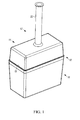
Fig. 1 is a schematic illustrations of a washer reservoir for a vehicle formed using an infrared pressure weld method; and -
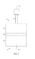
Fig. 2 is an enlarged schematic illustration of a front view of the washer reservoir and welding components showing section line 3-3; -
Fig. 3 is an enlarged schematic illustration of a cross-sectional view of the washer reservoir and welding components along the section line 3-3 ofFig. 2 ; -
Fig. 3A is an enlarged schematic illustration of a cross-sectional view of a section X the washer reservoir and welding components illustrating a weld zone; -
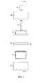
Fig. 4 is an exploded schematic front view illustration of the washer reservoir and welding components ofFigs. 2-3 showing section line 5-5; and -
Fig. 5 is an enlarged schematic illustration of a cross-sectional view of the washer reservoir and welding components along the section line 5-5 ofFig. 4 ; and -
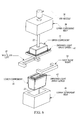
Fig. 6 is an enlarged schematic perspective illustration of the washer reservoir and welding components ofFigs. 4-5 . - The following description is merely exemplary in nature and is in no way intended to limit the disclosure, its application, or uses. For purposes of clarity, the same reference numbers will be used in the drawings to identify similar elements.
FIGS. 1-6 illustrate awasher reservoir 12 for a vehicle. Thereservoir 12 is intended for use in a washer system for a vehicle. However, thereservoir 12 can also be used for other types of applications. Thewasher reservoir 12 is formed by injection molding to for afirst reservoir portion 14 and asecond reservoir portion 16. Thefirst reservoir portion 14 and thesecond reservoir portion 16 are partially nested together with an overlappingportion 18. Thefirst reservoir portion 14 may define afluid inlet 20. Afluid passage 22 may connect to thefluid inlet 20. Thefluid inlet 20 andfluid passage 22 may be used when the washer reservoir is in the vehicle to add fluid into thereservoir 12. During the welding process thefluid inlet 20 andfluid passage 22 can be used to introduce pressurized air into thereservoir 12 as explained in further detail below. - Referring to
Figs. 1-6 thewasher reservoir 12 is shown with awelding apparatus 24. Thewelding apparatus 24 has afirst weld portion 26 and asecond weld portion 28. Thefirst weld portion 26 defines afirst cavity 30 corresponding to the shape of thefirst reservoir portion 14. Thesecond weld portion 28 defines asecond cavity 32 corresponding to the shape of thesecond reservoir portion 26. During the weld process thefirst reservoir portion 14 and thesecond reservoir portion 16 are nested in thefirst weld portion 26 andsecond weld portion 28. - An
aperture 34 in thefirst weld portion 26 accomodates thefluid inlet 20, allowing air to pass through thefluid inlet 20 andfluid passage 22 into thewasher reservoir 12. Anair nozzle 36 for theweld apparatus 24 can apply pressurized air into thewasher reservoir 12. The pressurized air forces thefirst reservoir portion 14 and thesecond reservoir portion 16 outward again thefirst weld portion 26 and thesecond weld portion 28 to hold thereservoir air nozzle 36 can be configured to match an opening into theair passage 22. -
Additional fluid inlets 20 may be used to allow pressurized air into the washer reservoir. For example, an aperture in thesecond portion 16, which is used to allow fluid to exit thereservoir 12 to the washer system during use in the vehicle, may also be use to allow pressurized air into thewasher reservoir 12 during the weld process. Other apertures may also be use to provide pressurized air during the weld process and then sealed or used for other purposes. Once skilled in the art would be able to determine the desired number ofinlets 20 to provide pressurized air during the weld process based upon the shape, size, and process for aparticular washer reservoir 12 andweld apparatus 24. - The
welding apparatus 24 also includes a pair ofslides 38 which fit over thewasher reservoir 12 at positions that correspond to the overlappingportion 18. Once thefirst reservoir portion 14 anfirst weld portion 26 are positioned together with thesecond reservoir portion 16 and thesecond weld portion 28 the overlappingportion 18 is formed. The overlappingportion 18 is the targeted weld zone. - During the weld process a first infrared
light array 40 is placed to surround thefirst reservoir portion 14 corresponding to what will be the overlappingportion 18 of thefirst weld portion 26. A second infraredlight array 42 is placed within thesecond reservoir portion 16 and also corresponds to the location of the overlappingportion 18 of thesecond weld portion 28. Infrared light is applied by the first infraredlight array 40 and the second infraredlight array 42 to weld thefirst reservoir portion 14 to thesecond reservoir portion 16 at the overlappingarea 18. The light array directs the heat to the desired specific weld zone(s). - The first and the second
light arrays portion 18 have reached a sufficient predetermined temperature. If necessary the first and the secondlight arrays first weld portion 26 and thesecond weld portion 28 are moved together to form the overlappingportion 18. The secondlight array 42 is located inside thesecond reservoir portion 16 and will likely need to be moved out of the way in order for thefirst reservoir portion 14 and the second reservoir portion to be assembled together. Likewise, the secondlight array 40 will likely need to be moved out of the way in order for theslides 38 to surround the overlappingportion 18. - From the outside, once assembled the pair of
slides 38, are moved into position to surround the overlappingportion 18. Thewasher reservoir 12 is filled with pressurized air, which forces the overlappingportion 18 outward against theslides 38. - Using internal pressure and the moving
nests upper portion 14 andlower portion 16 at the overlappingarea 18, to be pressed together and held using thenests light arrays weld surface 18 in the manner proposed removes the fracture point, increases weld surface area creating a stronger weld, and allows greater flexibility to respond to thermal and dynamic conditions acting on thereservoir 12 when it is assembled in the vehicle. - Therefore, referring to
Figures 1-6 , afluid reservoir 12 for a vehicle comprises afirst reservoir portion 14 and asecond reservoir portion 16, wherein the first and thesecond reservoir portions reservoir 12 to retain fluid for a washer system. An overlappingportion 18 of thefirst reservoir portion 14 and thesecond reservoir portion 16 is formed between them when theportions weld 19 formed using aninfrared weld apparatus 24. - The
infrared weld apparatus 24 comprises afirst nest 26 defining afirst weld cavity 30 to receive thefirst reservoir portion 14 and asecond nest 28 defining asecond weld cavity 32 to receive thesecond reservoir portion 16. Afirst light array 40 is located concentrically surrounding thefirst reservoir portion 14 at the location that will become the overlappingportion 18 and a secondlight array 42 is located concentrically inside thesecond reservoir portion 16 at the location that will become the overlappingportion 18, and parallel to thefirst light array 40. - The first and the second
light arrays portion 18 have reached a sufficient predetermined temperature. The first and the secondlight arrays first nest 26 and thesecond nest 28 are moved together to form the overlappingportion 18. - A pair of
slides 38 are moved in place to concentrically surround the overlappingportion 18 when thefirst reservoir portion 14,first weld portion 26,second reservoir portion 16 andsecond weld portion 28 are assembled together. Pressurized air is pumped into thefluid reservoir 12 after thefirst reservoir portion 14,first weld portion 26,second reservoir portion 16,second weld portion 28, and theslides 38 are assembled together. Thefirst reservoir portion 14 defines a fluid inlet 29 to receive the pressurized air when thefluid reservoir 12 is assembled in theweld apparatus 24 and to receive washer fluid when thefluid reservoir 12 is assembled in the vehicle. - A method of infrared welding a
fluid reservoir 12 for a vehicle comprises placing afirst reservoir portion 14 inside afirst cavity 30 defined by afirst weld portion 26 and asecond reservoir portion 16 inside asecond cavity 32 defined by asecond weld portion 28. Afirst light array 40 concentrically surrounds thefirst reservoir portion 14 and a secondlight array 42 is concentrically inside thesecond reservoir portion 16. Thefirst light array 40 and the secondlight array 42 apply infrared heat to thefirst reservoir portion 14 and thesecond reservoir portion 16. - The
first light array 40 and the secondlight array 42 are moved out of the way. Thefirst weld portion 26 and thesecond weld portion 28 are moved together until an overlappingportion 18 formed is formed by thefirst reservoir portion 14 and thesecond reservoir portion 16. A pair ofslides 38 are placed to concentrically surround the overlappingportion 18 and thereservoir 12 is filled with pressurized air to weld thefirst reservoir portion 16 to thesecond reservoir portion 18, forming theweld 19. wherein the first reservoir portion defines a fluid inlet to receive washer fluid when the fluid reservoir is assembled in the vehicle. - The
infrared weld apparatus 24 for welding afluid reservoir 12 comprises afirst weld portion 26 defining afirst weld cavity 30 to receive afirst reservoir portion 14 and asecond weld portion 28 defining asecond weld cavity 32 to receive asecond reservoir portion 16. Afirst light array 40 is located concentrically surrounding the overlappingportion 18 of thefirst reservoir portion 14 and a secondlight array 42 is located concentrically inside the overlappingportion 18 of thesecond reservoir portion 16, parallel to thefirst light array 40. Thefirst light array 40 and secondlight array 42 are configured to apply heat at the overlappingportion 18. A pair ofslides 38 concentrically surround an overlappingportion 18 of thefirst reservoir portion 14 and thesecond reservoir portion 16, when thefirst reservoir portion 14,first weld portion 26,second reservoir portion 16 andsecond weld portion 28 are assembled together. - Pressurized air is pumped into the
fluid reservoir 12 after thefirst reservoir portion 14,first weld portion 26,second reservoir portion 16,second weld portion 28, and theslides 38 are assembled together. - The
first reservoir portion 14 also defines a fluid inlet 29 to receive the pressurized air when thefluid reservoir 12 is assembled in theweld apparatus 24 and to receive washer fluid when thefluid reservoir 12 is assembled in the vehicle. - While the best modes for carrying out the invention have been described in detail the true scope of the disclosure should not be so limited, since those familiar with the art to which this invention relates will recognize various alternative designs and embodiments for practicing the invention within the scope of the appended claims.
Claims (8)
- A fluid reservoir for a washer system comprising:a first reservoir portion;a second reservoir portion, wherein the first and the second reservoir portions define a reservoir to retain fluid for a washer system; andan overlapping portion of the first reservoir portion and the second reservoir portion, wherein the overlapping portion is a weld formed using an infrared weld.
- The fluid reservoir of claim 1, wherein an infrared weld apparatus comprises;
a first weld portion defining a first weld cavity to receive the first reservoir portion;
a second weld portion defining a second weld cavity to receive the second reservoir portion;
a first light array located concentrically surrounding the overlapping portion;
a second light array located concentrically inside the overlapping portion, parallel to the first light array;
a pair of slides to concentrically surround the overlapping portion when the first reservoir portion, first weld portion, second reservoir portion and second weld portion are assembled together; and
wherein the first light array and second light array are configured to apply heat to the first reservoir portion to the second reservoir portion such that the first reservoir portion is welded to the second reservoir portion when the assembled together to form the overlapping portion. - The fluid reservoir of claim 2, wherein pressurized air is pumped into the fluid reservoir after the first reservoir portion, first weld portion, second reservoir portion and second weld portion, and the slides are assembled together after heat is applied by the first and second light array.
- The fluid reservoir of claim 3, wherein the first reservoir portion defines a fluid inlet to receive the pressurized air when the fluid reservoir is assembled in the weld apparatus and to receive washer fluid when the fluid reservoir is assembled in the vehicle.
- The fluid reservoir of one of the claims 1-4, wherein the first reservoir portion defines a fluid inlet to receive washer fluid when the fluid reservoir is assembled in the vehicle.
- A method of infrared welding a fluid reservoir for a vehicle comprising:placing a first reservoir portion inside a first cavity defined by a first weld portion;placing a second reservoir portion inside a second cavity defined by a second weld portion;placing a first light array concentrically surrounding the first reservoir portion;placing a second light array concentrically inside the second reservoir portion;applying infrared heat with the first light array and the second light array until a predetermined temperature on the first reservoir portion and the second reservoir portion is reached;removing the first light array and the second light array from the first and second reservoir portions;moving the first weld portion and the second weld portion together until an overlapping portion formed is formed by the first reservoir portion and the second reservoir portion;placing a pair of slides to concentrically surround the overlapping portion; andfilling the reservoir with pressurized air to weld the first reservoir portion to the second reservoir portion at the overlapping portion.
- The method of claim 6, wherein the first reservoir portion defines a fluid inlet to receive washer fluid when the fluid reservoir is assembled in the vehicle.
- The method of claim 7, further comprising pumping pressurized air into the fluid reservoir after the first reservoir portion, first weld portion, second reservoir portion and second weld portion, and the slides are assembled together such that the heated portions of the first reservoir and the second reservoir form a weld.
Applications Claiming Priority (2)
| Application Number | Priority Date | Filing Date | Title |
|---|---|---|---|
| US201462062320P | 2014-10-10 | 2014-10-10 | |
| US14/878,782 US10414101B2 (en) | 2014-10-10 | 2015-10-08 | Apparatus and method for an infrared pressure weld reservoir |
Publications (3)
| Publication Number | Publication Date |
|---|---|
| EP3006281A2 true EP3006281A2 (en) | 2016-04-13 |
| EP3006281A3 EP3006281A3 (en) | 2016-06-01 |
| EP3006281B1 EP3006281B1 (en) | 2025-08-13 |
Family
ID=54329393
Family Applications (1)
| Application Number | Title | Priority Date | Filing Date |
|---|---|---|---|
| EP15189325.2A Active EP3006281B1 (en) | 2014-10-10 | 2015-10-12 | Apparatus and method for infrared welding a fluid reservoir |
Country Status (3)
| Country | Link |
|---|---|
| US (1) | US10414101B2 (en) |
| EP (1) | EP3006281B1 (en) |
| JP (1) | JP6099717B2 (en) |
Citations (1)
| Publication number | Priority date | Publication date | Assignee | Title |
|---|---|---|---|---|
| US20040144780A1 (en) * | 2003-01-28 | 2004-07-29 | Brandner Brian W. | Fuel tank |
Family Cites Families (6)
| Publication number | Priority date | Publication date | Assignee | Title |
|---|---|---|---|---|
| JPS5828317A (en) | 1981-07-17 | 1983-02-19 | Kyoraku Co Ltd | Manufacture of tank with partition for automobile |
| US5454480A (en) * | 1993-10-21 | 1995-10-03 | Morris Holmes & Co. | Flangeless fuel tank |
| JP3776185B2 (en) | 1996-11-28 | 2006-05-17 | 日産自動車株式会社 | Resin fuel container and manufacturing method thereof |
| DE19909041A1 (en) | 1999-03-02 | 2000-09-07 | Mannesmann Vdo Ag | Arrangement of containers intended for assembly in a motor vehicle |
| DE10329990B3 (en) * | 2003-07-02 | 2005-04-21 | Benteler Automobiltechnik Gmbh | Pressure gas tank |
| WO2014032356A1 (en) * | 2012-08-28 | 2014-03-06 | 亚普汽车部件股份有限公司 | Automobile urea tank and forming method thereof |
-
2015
- 2015-10-08 US US14/878,782 patent/US10414101B2/en active Active
- 2015-10-09 JP JP2015201324A patent/JP6099717B2/en active Active
- 2015-10-12 EP EP15189325.2A patent/EP3006281B1/en active Active
Patent Citations (1)
| Publication number | Priority date | Publication date | Assignee | Title |
|---|---|---|---|---|
| US20040144780A1 (en) * | 2003-01-28 | 2004-07-29 | Brandner Brian W. | Fuel tank |
Also Published As
| Publication number | Publication date |
|---|---|
| JP6099717B2 (en) | 2017-03-22 |
| EP3006281A3 (en) | 2016-06-01 |
| EP3006281B1 (en) | 2025-08-13 |
| JP2016078844A (en) | 2016-05-16 |
| US20160101563A1 (en) | 2016-04-14 |
| US10414101B2 (en) | 2019-09-17 |
Similar Documents
| Publication | Publication Date | Title |
|---|---|---|
| US9371048B2 (en) | Energy absorbing member for a bumper assembly of a vehicle | |
| JP2017222345A (en) | Battery housing for automobile traction battery | |
| US20150300442A1 (en) | Damper for a Vehicle Having a Flange for Connecting an External Module Tube | |
| CN104804657A (en) | Bonded joint and bonding method of two hollow profiles | |
| JP5986243B2 (en) | How to connect the blade hose | |
| EP3717295B1 (en) | One-piece combined plastic urea and fuel tank with baffles, rotomoulded with a special mold heating system | |
| US10414101B2 (en) | Apparatus and method for an infrared pressure weld reservoir | |
| EP3009707A1 (en) | Air spring piston with integrated sealing | |
| CN104540697A (en) | Motor vehicle comprising a system for rapid access to the battery in the event of fire | |
| RU2017144618A (en) | HYBRID THERMOPLAST WELDING | |
| EP3098404A1 (en) | Blow-by heater | |
| KR20150048049A (en) | Method for connecting thermoplastic, coated components and plastic component | |
| US20170066076A1 (en) | Mechanical dimpling for vapor expression in welding | |
| KR102239013B1 (en) | Trailing arm bush for vehicle | |
| US10376993B2 (en) | Flash trap | |
| US10906250B2 (en) | Attachment part for connecting to a structural part | |
| JP6395253B2 (en) | Mounting structure for internal parts of automobile fuel tank | |
| US20160008915A1 (en) | Method of Connecting Two Components | |
| RU2018124510A (en) | METHOD FOR ASSEMBLING DOOR AND WINDOW FRAMES, PERFORMED FROM PLASTIC MATERIAL | |
| US10082161B2 (en) | Gas pressure actuator | |
| KR101745202B1 (en) | Door impact bar bracket, door assembly for vehicle including the same and manufacturing method of door assembly therefor | |
| US20170261266A1 (en) | Heat exchanger and method for producing a heat exchanger | |
| US20180017339A1 (en) | Thermal battery with encapsulated phase-change material and associated production method | |
| KR101304966B1 (en) | Impact pad assembly structure | |
| KR101514629B1 (en) | Laser welding apparatus and method |
Legal Events
| Date | Code | Title | Description |
|---|---|---|---|
| PUAI | Public reference made under article 153(3) epc to a published international application that has entered the european phase |
Free format text: ORIGINAL CODE: 0009012 |
|
| AK | Designated contracting states |
Kind code of ref document: A2 Designated state(s): AL AT BE BG CH CY CZ DE DK EE ES FI FR GB GR HR HU IE IS IT LI LT LU LV MC MK MT NL NO PL PT RO RS SE SI SK SM TR |
|
| AX | Request for extension of the european patent |
Extension state: BA ME |
|
| PUAL | Search report despatched |
Free format text: ORIGINAL CODE: 0009013 |
|
| AK | Designated contracting states |
Kind code of ref document: A3 Designated state(s): AL AT BE BG CH CY CZ DE DK EE ES FI FR GB GR HR HU IE IS IT LI LT LU LV MC MK MT NL NO PL PT RO RS SE SI SK SM TR |
|
| AX | Request for extension of the european patent |
Extension state: BA ME |
|
| RIC1 | Information provided on ipc code assigned before grant |
Ipc: B60S 1/50 20060101AFI20160422BHEP Ipc: B29C 65/14 20060101ALI20160422BHEP Ipc: B29C 65/78 20060101ALN20160422BHEP |
|
| STAA | Information on the status of an ep patent application or granted ep patent |
Free format text: STATUS: REQUEST FOR EXAMINATION WAS MADE |
|
| 17P | Request for examination filed |
Effective date: 20161201 |
|
| RBV | Designated contracting states (corrected) |
Designated state(s): AL AT BE BG CH CY CZ DE DK EE ES FI FR GB GR HR HU IE IS IT LI LT LU LV MC MK MT NL NO PL PT RO RS SE SI SK SM TR |
|
| STAA | Information on the status of an ep patent application or granted ep patent |
Free format text: STATUS: EXAMINATION IS IN PROGRESS |
|
| 17Q | First examination report despatched |
Effective date: 20190425 |
|
| RAP1 | Party data changed (applicant data changed or rights of an application transferred) |
Owner name: CONTINENTAL AUTOMOTIVE SYSTEMS, INC. |
|
| GRAP | Despatch of communication of intention to grant a patent |
Free format text: ORIGINAL CODE: EPIDOSNIGR1 |
|
| STAA | Information on the status of an ep patent application or granted ep patent |
Free format text: STATUS: GRANT OF PATENT IS INTENDED |
|
| INTG | Intention to grant announced |
Effective date: 20250328 |
|
| GRAS | Grant fee paid |
Free format text: ORIGINAL CODE: EPIDOSNIGR3 |
|
| GRAA | (expected) grant |
Free format text: ORIGINAL CODE: 0009210 |
|
| STAA | Information on the status of an ep patent application or granted ep patent |
Free format text: STATUS: THE PATENT HAS BEEN GRANTED |
|
| AK | Designated contracting states |
Kind code of ref document: B1 Designated state(s): AL AT BE BG CH CY CZ DE DK EE ES FI FR GB GR HR HU IE IS IT LI LT LU LV MC MK MT NL NO PL PT RO RS SE SI SK SM TR |
|
| REG | Reference to a national code |
Ref country code: GB Ref legal event code: FG4D |
|
| REG | Reference to a national code |
Ref country code: CH Ref legal event code: EP |
|
| REG | Reference to a national code |
Ref country code: DE Ref legal event code: R096 Ref document number: 602015092168 Country of ref document: DE |
|
| REG | Reference to a national code |
Ref country code: IE Ref legal event code: FG4D |
|
| REG | Reference to a national code |
Ref country code: CH Ref legal event code: W10 Free format text: ST27 STATUS EVENT CODE: U-0-0-W10-W00 (AS PROVIDED BY THE NATIONAL OFFICE) Effective date: 20251217 Ref country code: NL Ref legal event code: MP Effective date: 20250813 |
|
| PG25 | Lapsed in a contracting state [announced via postgrant information from national office to epo] |
Ref country code: IS Free format text: LAPSE BECAUSE OF FAILURE TO SUBMIT A TRANSLATION OF THE DESCRIPTION OR TO PAY THE FEE WITHIN THE PRESCRIBED TIME-LIMIT Effective date: 20251213 |
|
| PGFP | Annual fee paid to national office [announced via postgrant information from national office to epo] |
Ref country code: DE Payment date: 20251031 Year of fee payment: 11 |
|
| PG25 | Lapsed in a contracting state [announced via postgrant information from national office to epo] |
Ref country code: NO Free format text: LAPSE BECAUSE OF FAILURE TO SUBMIT A TRANSLATION OF THE DESCRIPTION OR TO PAY THE FEE WITHIN THE PRESCRIBED TIME-LIMIT Effective date: 20251113 |
|
| REG | Reference to a national code |
Ref country code: LT Ref legal event code: MG9D |
|
| PG25 | Lapsed in a contracting state [announced via postgrant information from national office to epo] |
Ref country code: PT Free format text: LAPSE BECAUSE OF FAILURE TO SUBMIT A TRANSLATION OF THE DESCRIPTION OR TO PAY THE FEE WITHIN THE PRESCRIBED TIME-LIMIT Effective date: 20251215 |
|
| PG25 | Lapsed in a contracting state [announced via postgrant information from national office to epo] |
Ref country code: FI Free format text: LAPSE BECAUSE OF FAILURE TO SUBMIT A TRANSLATION OF THE DESCRIPTION OR TO PAY THE FEE WITHIN THE PRESCRIBED TIME-LIMIT Effective date: 20250813 |
|
| RAP4 | Party data changed (patent owner data changed or rights of a patent transferred) |
Owner name: AUMOVIO SYSTEMS, INC. |
|
| PG25 | Lapsed in a contracting state [announced via postgrant information from national office to epo] |
Ref country code: HR Free format text: LAPSE BECAUSE OF FAILURE TO SUBMIT A TRANSLATION OF THE DESCRIPTION OR TO PAY THE FEE WITHIN THE PRESCRIBED TIME-LIMIT Effective date: 20250813 Ref country code: NL Free format text: LAPSE BECAUSE OF FAILURE TO SUBMIT A TRANSLATION OF THE DESCRIPTION OR TO PAY THE FEE WITHIN THE PRESCRIBED TIME-LIMIT Effective date: 20250813 |
|
| PG25 | Lapsed in a contracting state [announced via postgrant information from national office to epo] |
Ref country code: GR Free format text: LAPSE BECAUSE OF FAILURE TO SUBMIT A TRANSLATION OF THE DESCRIPTION OR TO PAY THE FEE WITHIN THE PRESCRIBED TIME-LIMIT Effective date: 20251114 |
|
| PG25 | Lapsed in a contracting state [announced via postgrant information from national office to epo] |
Ref country code: SE Free format text: LAPSE BECAUSE OF FAILURE TO SUBMIT A TRANSLATION OF THE DESCRIPTION OR TO PAY THE FEE WITHIN THE PRESCRIBED TIME-LIMIT Effective date: 20250813 |
|
| PG25 | Lapsed in a contracting state [announced via postgrant information from national office to epo] |
Ref country code: LV Free format text: LAPSE BECAUSE OF FAILURE TO SUBMIT A TRANSLATION OF THE DESCRIPTION OR TO PAY THE FEE WITHIN THE PRESCRIBED TIME-LIMIT Effective date: 20250813 |
|
| PG25 | Lapsed in a contracting state [announced via postgrant information from national office to epo] |
Ref country code: PL Free format text: LAPSE BECAUSE OF FAILURE TO SUBMIT A TRANSLATION OF THE DESCRIPTION OR TO PAY THE FEE WITHIN THE PRESCRIBED TIME-LIMIT Effective date: 20250813 Ref country code: BG Free format text: LAPSE BECAUSE OF FAILURE TO SUBMIT A TRANSLATION OF THE DESCRIPTION OR TO PAY THE FEE WITHIN THE PRESCRIBED TIME-LIMIT Effective date: 20250813 |
|
| PG25 | Lapsed in a contracting state [announced via postgrant information from national office to epo] |
Ref country code: RS Free format text: LAPSE BECAUSE OF FAILURE TO SUBMIT A TRANSLATION OF THE DESCRIPTION OR TO PAY THE FEE WITHIN THE PRESCRIBED TIME-LIMIT Effective date: 20251113 |
|
| PG25 | Lapsed in a contracting state [announced via postgrant information from national office to epo] |
Ref country code: ES Free format text: LAPSE BECAUSE OF FAILURE TO SUBMIT A TRANSLATION OF THE DESCRIPTION OR TO PAY THE FEE WITHIN THE PRESCRIBED TIME-LIMIT Effective date: 20250813 |
|
| REG | Reference to a national code |
Ref country code: AT Ref legal event code: MK05 Ref document number: 1824377 Country of ref document: AT Kind code of ref document: T Effective date: 20250813 |
|
| PG25 | Lapsed in a contracting state [announced via postgrant information from national office to epo] |
Ref country code: RO Free format text: LAPSE BECAUSE OF FAILURE TO SUBMIT A TRANSLATION OF THE DESCRIPTION OR TO PAY THE FEE WITHIN THE PRESCRIBED TIME-LIMIT Effective date: 20250813 |
|
| PG25 | Lapsed in a contracting state [announced via postgrant information from national office to epo] |
Ref country code: SM Free format text: LAPSE BECAUSE OF FAILURE TO SUBMIT A TRANSLATION OF THE DESCRIPTION OR TO PAY THE FEE WITHIN THE PRESCRIBED TIME-LIMIT Effective date: 20250813 |
|
| PG25 | Lapsed in a contracting state [announced via postgrant information from national office to epo] |
Ref country code: DK Free format text: LAPSE BECAUSE OF FAILURE TO SUBMIT A TRANSLATION OF THE DESCRIPTION OR TO PAY THE FEE WITHIN THE PRESCRIBED TIME-LIMIT Effective date: 20250813 |
|
| PG25 | Lapsed in a contracting state [announced via postgrant information from national office to epo] |
Ref country code: AT Free format text: LAPSE BECAUSE OF FAILURE TO SUBMIT A TRANSLATION OF THE DESCRIPTION OR TO PAY THE FEE WITHIN THE PRESCRIBED TIME-LIMIT Effective date: 20250813 |
|
| PG25 | Lapsed in a contracting state [announced via postgrant information from national office to epo] |
Ref country code: IT Free format text: LAPSE BECAUSE OF FAILURE TO SUBMIT A TRANSLATION OF THE DESCRIPTION OR TO PAY THE FEE WITHIN THE PRESCRIBED TIME-LIMIT Effective date: 20250813 |
|
| PG25 | Lapsed in a contracting state [announced via postgrant information from national office to epo] |
Ref country code: CZ Free format text: LAPSE BECAUSE OF FAILURE TO SUBMIT A TRANSLATION OF THE DESCRIPTION OR TO PAY THE FEE WITHIN THE PRESCRIBED TIME-LIMIT Effective date: 20250813 |
|
| PG25 | Lapsed in a contracting state [announced via postgrant information from national office to epo] |
Ref country code: SK Free format text: LAPSE BECAUSE OF FAILURE TO SUBMIT A TRANSLATION OF THE DESCRIPTION OR TO PAY THE FEE WITHIN THE PRESCRIBED TIME-LIMIT Effective date: 20250813 Ref country code: EE Free format text: LAPSE BECAUSE OF FAILURE TO SUBMIT A TRANSLATION OF THE DESCRIPTION OR TO PAY THE FEE WITHIN THE PRESCRIBED TIME-LIMIT Effective date: 20250813 |