EP3005973A1 - System of prosthetic attachments for dental implants, use and method of use thereof - Google Patents
System of prosthetic attachments for dental implants, use and method of use thereof Download PDFInfo
- Publication number
- EP3005973A1 EP3005973A1 EP14741992.3A EP14741992A EP3005973A1 EP 3005973 A1 EP3005973 A1 EP 3005973A1 EP 14741992 A EP14741992 A EP 14741992A EP 3005973 A1 EP3005973 A1 EP 3005973A1
- Authority
- EP
- European Patent Office
- Prior art keywords
- implant
- dental
- alveolus
- preferentially
- pillar
- Prior art date
- Legal status (The legal status is an assumption and is not a legal conclusion. Google has not performed a legal analysis and makes no representation as to the accuracy of the status listed.)
- Granted
Links
- 239000004053 dental implant Substances 0.000 title claims abstract description 44
- 238000000034 method Methods 0.000 title claims abstract description 10
- 239000007943 implant Substances 0.000 claims abstract description 83
- 210000003781 tooth socket Anatomy 0.000 claims abstract description 51
- 239000013589 supplement Substances 0.000 claims abstract description 33
- 210000000988 bone and bone Anatomy 0.000 claims description 8
- 210000003456 pulmonary alveoli Anatomy 0.000 claims description 8
- 230000003993 interaction Effects 0.000 claims description 4
- 230000014759 maintenance of location Effects 0.000 claims description 4
- QCWXUUIWCKQGHC-UHFFFAOYSA-N Zirconium Chemical compound [Zr] QCWXUUIWCKQGHC-UHFFFAOYSA-N 0.000 claims description 2
- 239000000463 material Substances 0.000 claims description 2
- 238000003801 milling Methods 0.000 claims description 2
- 238000000465 moulding Methods 0.000 claims description 2
- 239000000126 substance Substances 0.000 claims description 2
- 229910052726 zirconium Inorganic materials 0.000 claims description 2
- 208000007536 Thrombosis Diseases 0.000 claims 1
- 230000035876 healing Effects 0.000 abstract description 4
- 210000001519 tissue Anatomy 0.000 description 5
- 230000002349 favourable effect Effects 0.000 description 3
- 238000011084 recovery Methods 0.000 description 3
- 238000000605 extraction Methods 0.000 description 2
- 230000001737 promoting effect Effects 0.000 description 2
- 230000011664 signaling Effects 0.000 description 2
- 210000004872 soft tissue Anatomy 0.000 description 2
Images


Classifications
-
- A—HUMAN NECESSITIES
- A61—MEDICAL OR VETERINARY SCIENCE; HYGIENE
- A61C—DENTISTRY; APPARATUS OR METHODS FOR ORAL OR DENTAL HYGIENE
- A61C8/00—Means to be fixed to the jaw-bone for consolidating natural teeth or for fixing dental prostheses thereon; Dental implants; Implanting tools
- A61C8/0048—Connecting the upper structure to the implant, e.g. bridging bars
- A61C8/005—Connecting devices for joining an upper structure with an implant member, e.g. spacers
-
- A—HUMAN NECESSITIES
- A61—MEDICAL OR VETERINARY SCIENCE; HYGIENE
- A61C—DENTISTRY; APPARATUS OR METHODS FOR ORAL OR DENTAL HYGIENE
- A61C8/00—Means to be fixed to the jaw-bone for consolidating natural teeth or for fixing dental prostheses thereon; Dental implants; Implanting tools
- A61C8/0018—Means to be fixed to the jaw-bone for consolidating natural teeth or for fixing dental prostheses thereon; Dental implants; Implanting tools characterised by the shape
-
- A—HUMAN NECESSITIES
- A61—MEDICAL OR VETERINARY SCIENCE; HYGIENE
- A61C—DENTISTRY; APPARATUS OR METHODS FOR ORAL OR DENTAL HYGIENE
- A61C8/00—Means to be fixed to the jaw-bone for consolidating natural teeth or for fixing dental prostheses thereon; Dental implants; Implanting tools
- A61C8/0093—Features of implants not otherwise provided for
- A61C8/0098—Immediate loaded implants
-
- A—HUMAN NECESSITIES
- A61—MEDICAL OR VETERINARY SCIENCE; HYGIENE
- A61C—DENTISTRY; APPARATUS OR METHODS FOR ORAL OR DENTAL HYGIENE
- A61C8/00—Means to be fixed to the jaw-bone for consolidating natural teeth or for fixing dental prostheses thereon; Dental implants; Implanting tools
- A61C8/0048—Connecting the upper structure to the implant, e.g. bridging bars
- A61C8/0077—Connecting the upper structure to the implant, e.g. bridging bars with shape following the gingival surface or the bone surface
-
- A—HUMAN NECESSITIES
- A61—MEDICAL OR VETERINARY SCIENCE; HYGIENE
- A61C—DENTISTRY; APPARATUS OR METHODS FOR ORAL OR DENTAL HYGIENE
- A61C8/00—Means to be fixed to the jaw-bone for consolidating natural teeth or for fixing dental prostheses thereon; Dental implants; Implanting tools
- A61C8/008—Healing caps or the like
Definitions
- the present invention refers to the field of prosthetic supplements for dental implants, in particular to systems of prosthetic supplements for dental implants including an implant support and an implant pillar.
- the present invention further refers to the preferred use of the system of prosthetic supplements for dental implants and to a method of use of such a type of system of prosthetic supplements for dental implants.
- the goal of the present invention is to provide a system of prosthetic supplements for dental implants, in particular preferentially comprising a plurality of dental implants that present a respective implant support and implant pillar for application of a prosthetic crown, or similar device, that provides better recovery conditions of the soft and hard tissues of the implant alveolus, in particular promoting better clot development conditions inside of the implant alveolus.
- a system of prosthetic supplements for dental implants that present an implant support and an implant pillar provided so that they engage each other and engage in a respective dental alveolus, in particular configured with a cross section of smaller dimension than the alveolar section of said dental alveolus, and are disposed on said dental alveolus so that, when executing a respective assembly and placement, there remains a free alveolar space in the implant alveolus that develops preferentially in a substantially continuous manner on the exterior side of the dental alveolus with reference to the mouth cavity, in particular along at least part of a respective alveolus wall.
- the implant support and the implant pillar are configured and disposed so that said free alveolar space correspond to at least a fraction, preferentially a fraction of laminar form of the dental alveolus, and extends along at least part, preferentially most part of the alveolus wall, particularly preferred until the zone of the alveolar crest, and is closed relative to the outside.
- this free alveolar space favors clot development and, therefore, promotes a faster healing of the dental alveolus after placing the implant.
- the implant support is provided so that the respective support base results in engagement with the base of the dental alveolus and the support top results somewhat below of the bone crest of the dental alveolus, preferentially at a distance between 1 mm and 4 mm, particularly preferred at about 2 mm, being in this case disposed preferentially relative to the cross section of the dental alveolus so as to provide said free alveolar space.
- the implant support thus ensure a reliable fixation of the implant to the bone structure of alveolar surround, while simultaneously providing free alveolar space that is favorable to a more rapid recovery of the bone and soft tissues after placement of the implant.
- the implant pillar presents an emerging profile configured so as to minimize the zone of interaction with the edge of alveolar crest, while thereby closing said free alveolar space.
- the implant pillar presents an emerging profile configured so as to maximize the free alveolar space in the proximity of the alveolar crest while thereby closing said free alveolar space.
- the emerging profile is configured so as to sit in surface and/or minimal pressure at least in the perimeter part of the alveolar crest that is on the exterior side with relation to the mouth cavity, while simultaneously ensuring a sufficient proximity to thereby close the free alveolar space relative to the exterior of the dental alveolus.
- the implant pillar presents an emerging profile with a contour including a first profile zone preferentially provided in a concave configuration, and a second profile zone provided in a convex configuration in relation to the alveolar wall, so that the interaction with the edge of the alveolar crest is done, at least in most of its extension, by the convex zone of the emerging profile.
- the implant pillar presents an emerging profile that develops along an extension (x) and a height (y), whereby the dimensions and/or the relation between the extension (x) and the height (y) of the emerging profile are determined as a function of the dimension and/or of the type of respective dental alveolus.
- the relation between the extension (x) and the height (y) of the emerging profile is in the interval from 0,5:1 up to 3:1, preferentially in the interval from 1:1 up to 2:1.
- the present invention further discloses several preferred embodiments of the aforementioned emerging profile.
- the first and second zones of the emerging profile are provided in a curved configuration, preferentially substantially continuous.
- the implant pillar presents an emerging profile that develops along at least part, preferentially at least most part of the exterior surface of the base element, and along at least part, preferentially at least most part of half the cross section of the base element.
- the base of pillar presents an asymmetric cross section, in particular with the emerging profile developing along at least most part of half the perimeter thereof.
- the implant pillar presents a base element and a retention element adapted for engagement with an implant crown, whereby the base element presents said emerging profile in at least part of its side face.
- Another objective is to provide a system of prosthetic supplements for dental implants that comprises a plurality of elements or models of previously defined configurations and dimensions in view of thereby corresponding to the needs of at least the majority of the cases of dental alveolus after extraction.
- the system of dental implants is provided in form of sets of kits adequate for use in implants, regardless of whether immediate or not, in respectively representative dental alveolus.
- the implant pillar is produced in a single piece, preferentially by means of molding or tridimensional milling.
- the implant pillar is produced in zirconium, or material presenting similar physical and chemical proprieties.
- Another objective of the present invention is to provide an advantageous use of the system of prosthetic supplements for dental implants according to the invention.
- Another objective of the present invention is to provide a method of use of said system of prosthetic supplements for dental implants, whereby this objective is solved by means of a method whereby a dental implant is placed according to the steps identified in claim 20.
- Figure 1 presents a schematic representation in side cut view through a vertical symmetry plane, of a system (1) of prosthetic supplements for dental implants according to the invention.
- a dental implant of a system (1) of prosthetic supplements for dental implants such as known in prior art, presents a first implant part, hereinafter designated by implant support (2) that is provided in an elongated format of substantially cylindrical type, including a respective support base (21) and support top (22), and a second implant part, hereinafter designated by implant pillar (3), that is provided on the top of the implant support (3).
- the implant pillar (3) is usually provide with a base element (31) provided with a cross section that corresponds substantially to the cross section of the support top (22) so as to better engage with the implant support (2) arranged below thereof, and with a retention element (32) provided to engage with a prosthetic crown (8) arranged above thereof.
- Figure 7 presents the version whereby the implant pillar (3) and a prosthetic crown (8) arranged above are provided as a single device.
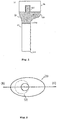
- Figures 2 and 8 show the implant support (2) ad the implant pillar (3) in top views.
- the implant pillar (3) according to the present invention is preferentially provided with a symmetry profile (identified by A-A') and with an asymmetric cross section, in particular including an emerging profile (33) on one side.
- Figure 3 presents a schematic representation of a dental alveolus (4) in front view relative to the interior of the mouth cavity, in particular signaling the general configuration and structure of soft and hard tissues.
- an exterior zone of soft tissues with dotted shadowing
- a zone of hard tissues with dashed shadowing
- alveolar wall zone (6) and the edge zone of the dental alveolus (4) hereinafter designated by alveolar crest (7).
- the dental implant according to the system (1) of prosthetic supplements for dental implants according to the present invention is provided so that there results a free alveolar space (5) disposed on the exterior side of the dental alveolus (4) relative to the mouth cavity.
- This free alveolar space (5) corresponds to at least a fraction of the volume of the dental alveolus (4), including a fraction of substantially laminar format.
- the implant support (2) is provided, including dimensioned and configured, so that the support base (21) engages in part of the alveolar wall (6) and of the alveolus base, and the support top (22) remains arranged somewhat below, preferentially at a distance (a) of between 1 mm to 4 mm, particularly preferred at about 2 mm from the proximal bone crest.
- said free alveolar space (5) develops along most part of the alveolar wall (6) that is in each case on the exterior side with relation to the mouth cavity, thereby providing better conditions for the development of the healing clot.
- the support pillar (3) presents an emerging profile (33) at least in the zone that is disposed on the exterior side of the dental alveolus (4) with relation to the mouth cavity, whereby this emerging profile (33) is configured so as to closed said free alveolar space (5), thereby exerting the least pressure and with the least proximity surface relative to the alveolar crest (7).
- said emerging profile (33) is configured in a curved form, including a convex part and a concave part, so as to maximize the free alveolar space (5) in the zone of the alveolar crest (6), and to minimize the pressure exerted and the respective contact surface with said alveolar crest (6).
- this emerging profile (33) are possible, notably in view of different characteristics and dimensions of the dental alveolus (4) being considered.
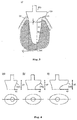
- Figure 4 presents schematic representations, in side cut view above, and in top view below, of three implant pillars (3) of a (1) of prosthetic supplements for dental implants according to the invention.
- the implant pillars (3) for immediate placement of a prosthetic crown present an emerging profile (33) that develops along different dimensions (x, y). These dimensions (x, y) are previously defined in view of a set of parameters generally associated with the general conditions and representative of the majority of dental alveolus (4).
- Figure 5 presents a schematic representation of a dental alveolus (4) in front view with relation to the interior of the mouth cavity, in particular thereby signaling the general configuration and the structure of soft and hard tissues.
- the embodiment of prosthetic supplement adapted for use without immediate placement of the prosthetic crown.
- the dimension h is previously defined in view of a set of parameters generally associated with general conditions, and representative of a majority of said dental alveolus (4) as a function of a height that should always be more coronal above of the gingival limit.
- Figure 6 presents schematic representations, in side cut view above, and in top view below, of three implant pillars (3) of a system (1) of prosthetic supplements for dental implants according to the invention, in the embodiment whereby there is not placed a prosthetic crown at the time of placing the dental implant.
Landscapes
- Health & Medical Sciences (AREA)
- Oral & Maxillofacial Surgery (AREA)
- Orthopedic Medicine & Surgery (AREA)
- Dentistry (AREA)
- Epidemiology (AREA)
- Life Sciences & Earth Sciences (AREA)
- Animal Behavior & Ethology (AREA)
- General Health & Medical Sciences (AREA)
- Public Health (AREA)
- Veterinary Medicine (AREA)
- Dental Prosthetics (AREA)
Abstract
Description
- The present invention refers to the field of prosthetic supplements for dental implants, in particular to systems of prosthetic supplements for dental implants including an implant support and an implant pillar.
- The present invention further refers to the preferred use of the system of prosthetic supplements for dental implants and to a method of use of such a type of system of prosthetic supplements for dental implants.
- When considering the extraction of a tooth and placement of an implant in a respective dental alveolus, there is the issue of the conditions more favorable to the recovery of the soft and hard biologic tissues affected by such intervention, in particular in the zone of the alveolar crest, and the creation of favorable conditions to a subsequent placement of prosthetic crown in said implant. This purpose has particular application in the so-called immediate implants, where a prosthetic crown is applied immediately after the placement of a respective implant. This type of implants presents several advantages, including in terms of minimizing the associated interventions and discomfort.
- There are several solutions already known in prior art that disclose emerging profile configurations of an implant pillar. Examples include the documents
WO 2006/138353 A2 ,WO 2010/141342 A2 andWO 2012/158769 A1 . - However, all of these documents refer only to the evolution of such an emerging profile above of the alveolar crown. None of the prior art documents addresses the problem of providing the dental implant in view of promoting the conditions of rapid healing, in particular resulting from the development of alveolar clot, not being therefore suited for immediate implants; only for implants placed in already healed bone crests.
- The goal of the present invention is to provide a system of prosthetic supplements for dental implants, in particular preferentially comprising a plurality of dental implants that present a respective implant support and implant pillar for application of a prosthetic crown, or similar device, that provides better recovery conditions of the soft and hard tissues of the implant alveolus, in particular promoting better clot development conditions inside of the implant alveolus.
- This goal is attained according to the present invention by means of a system of prosthetic supplements for dental implants that present an implant support and an implant pillar provided so that they engage each other and engage in a respective dental alveolus, in particular configured with a cross section of smaller dimension than the alveolar section of said dental alveolus, and are disposed on said dental alveolus so that, when executing a respective assembly and placement, there remains a free alveolar space in the implant alveolus that develops preferentially in a substantially continuous manner on the exterior side of the dental alveolus with reference to the mouth cavity, in particular along at least part of a respective alveolus wall.
- According to a particular embodiment, the implant support and the implant pillar are configured and disposed so that said free alveolar space correspond to at least a fraction, preferentially a fraction of laminar form of the dental alveolus, and extends along at least part, preferentially most part of the alveolus wall, particularly preferred until the zone of the alveolar crest, and is closed relative to the outside. In fact, it has been verified that this free alveolar space favors clot development and, therefore, promotes a faster healing of the dental alveolus after placing the implant.
- According to another inventive aspect, the implant support is provided so that the respective support base results in engagement with the base of the dental alveolus and the support top results somewhat below of the bone crest of the dental alveolus, preferentially at a distance between 1 mm and 4 mm, particularly preferred at about 2 mm, being in this case disposed preferentially relative to the cross section of the dental alveolus so as to provide said free alveolar space. The implant support thus ensure a reliable fixation of the implant to the bone structure of alveolar surround, while simultaneously providing free alveolar space that is favorable to a more rapid recovery of the bone and soft tissues after placement of the implant.
- According to another inventive aspect, the implant pillar presents an emerging profile configured so as to minimize the zone of interaction with the edge of alveolar crest, while thereby closing said free alveolar space. According to a preferred embodiment, the implant pillar presents an emerging profile configured so as to maximize the free alveolar space in the proximity of the alveolar crest while thereby closing said free alveolar space.
- According to another inventive aspect, the emerging profile is configured so as to sit in surface and/or minimal pressure at least in the perimeter part of the alveolar crest that is on the exterior side with relation to the mouth cavity, while simultaneously ensuring a sufficient proximity to thereby close the free alveolar space relative to the exterior of the dental alveolus.
- De according to a preferred embodiment, the implant pillar presents an emerging profile with a contour including a first profile zone preferentially provided in a concave configuration, and a second profile zone provided in a convex configuration in relation to the alveolar wall, so that the interaction with the edge of the alveolar crest is done, at least in most of its extension, by the convex zone of the emerging profile.
- According to a preferred embodiment, the implant pillar presents an emerging profile that develops along an extension (x) and a height (y), whereby the dimensions and/or the relation between the extension (x) and the height (y) of the emerging profile are determined as a function of the dimension and/or of the type of respective dental alveolus. In particular, it is preferred when the relation between the extension (x) and the height (y) of the emerging profile is in the interval from 0,5:1 up to 3:1, preferentially in the interval from 1:1 up to 2:1.
- The present invention further discloses several preferred embodiments of the aforementioned emerging profile.
- According to a first preferred embodiment, the first and second zones of the emerging profile are provided in a curved configuration, preferentially substantially continuous. According to another embodiment, the implant pillar presents an emerging profile that develops along at least part, preferentially at least most part of the exterior surface of the base element, and along at least part, preferentially at least most part of half the cross section of the base element. According to another preferred embodiment, the base of pillar presents an asymmetric cross section, in particular with the emerging profile developing along at least most part of half the perimeter thereof. According to another preferred embodiment, the implant pillar presents a base element and a retention element adapted for engagement with an implant crown, whereby the base element presents said emerging profile in at least part of its side face.
- Another objective is to provide a system of prosthetic supplements for dental implants that comprises a plurality of elements or models of previously defined configurations and dimensions in view of thereby corresponding to the needs of at least the majority of the cases of dental alveolus after extraction.
- This goal is solved according to the present invention by means of at least two, preferentially at least four models of prosthetic supplements for dental implants that present different dimensions of implant supports and/or of implant bases, including respective emerging profiles, configured and dimensioned so that they can be used with the generality of the dimensions and/or types of dental alveolus at least for a given age group of a given animal species. According to a preferred embodiment, the system of dental implants is provided in form of sets of kits adequate for use in implants, regardless of whether immediate or not, in respectively representative dental alveolus.
- According to a preferred embodiment, the implant pillar is produced in a single piece, preferentially by means of molding or tridimensional milling. According to another preferred embodiment, the implant pillar is produced in zirconium, or material presenting similar physical and chemical proprieties.
- Another objective of the present invention is to provide an advantageous use of the system of prosthetic supplements for dental implants according to the invention.
- This goal is solved through the use of the system of prosthetic supplements for dental implants whenever there is a placement of the prosthetic crown immediately after the placement of the implant support and pillar in a dental alveolus, in general, and according to claim 19 in particular.
- Another objective of the present invention is to provide a method of use of said system of prosthetic supplements for dental implants, whereby this objective is solved by means of a method whereby a dental implant is placed according to the steps identified in claim 20.
- Preferred embodiments are disclosed in the depending claims.
- The invention shall hereinafter be explained in more detail based upon preferred embodiments and the attached Figures.
- The Figures show:
- Figure 1:
- schematic representation in side view, in a view partially in cut, of an embodiment of a system (1) of prosthetic supplements for dental implants according to the invention (prosthetic version where the pillar and the crown are two components);
- Figure 2:
- schematic representation in top view of an embodiment of a system (1) of prosthetic supplements for dental implants according to the invention;
- Figure 3:
- schematic representation in front cut view, of a dental alveolus (2) with an embodiment of a system (1) of prosthetic supplements for dental implants according to the invention (prosthetic supplement version for immediate use of a prosthetic crown);
- Figure 4:
- schematic representation in side view and in top view (bottom) of a plurality of a system (1) of prosthetic supplements for dental implants according to the present invention;
- Figure 5:
- schematic representation in front cut view of a dental alveolus (2) with an embodiment of a system (1) of prosthetic supplements for dental implants according to the invention (prosthetic supplement version for use without immediate placement of a crown);
- Figure 6:
- schematic representations in side view and in top view (bottom), of a plurality of units of a system (1) of prosthetic supplements for dental implants according to the present invention;
- Figure 7:
- schematic representation in a partially in cut side view of an embodiment of system (1) of prosthetic supplements for dental implants according to the invention (prosthetic version where the pillar and the crown are a single component);
- Figure 8:
- schematic representation in top view of an embodiment of a system (1) of prosthetic supplements for dental implants according to the invention.
-
Figure 1 presents a schematic representation in side cut view through a vertical symmetry plane, of a system (1) of prosthetic supplements for dental implants according to the invention. A dental implant of a system (1) of prosthetic supplements for dental implants, such as known in prior art, presents a first implant part, hereinafter designated by implant support (2) that is provided in an elongated format of substantially cylindrical type, including a respective support base (21) and support top (22), and a second implant part, hereinafter designated by implant pillar (3), that is provided on the top of the implant support (3). The implant pillar (3) is usually provide with a base element (31) provided with a cross section that corresponds substantially to the cross section of the support top (22) so as to better engage with the implant support (2) arranged below thereof, and with a retention element (32) provided to engage with a prosthetic crown (8) arranged above thereof.Figure 7 presents the version whereby the implant pillar (3) and a prosthetic crown (8) arranged above are provided as a single device. -
Figures 2 and8 show the implant support (2) ad the implant pillar (3) in top views. - As one can observe from
Figures 1, 2, 7 , the implant pillar (3) according to the present invention is preferentially provided with a symmetry profile (identified by A-A') and with an asymmetric cross section, in particular including an emerging profile (33) on one side.e 8 -
Figure 3 presents a schematic representation of a dental alveolus (4) in front view relative to the interior of the mouth cavity, in particular signaling the general configuration and structure of soft and hard tissues. In particular, there is identified an exterior zone of soft tissues (with dotted shadowing) and a zone of hard tissues (with dashed shadowing) that surround the alveolar cavity. In the drawing there can further be recognized the alveolar wall zone (6) and the edge zone of the dental alveolus (4), hereinafter designated by alveolar crest (7). - As it can be observed, the dental implant according to the system (1) of prosthetic supplements for dental implants according to the present invention is provided so that there results a free alveolar space (5) disposed on the exterior side of the dental alveolus (4) relative to the mouth cavity. This free alveolar space (5) corresponds to at least a fraction of the volume of the dental alveolus (4), including a fraction of substantially laminar format.
- According to an inventive aspect, the implant support (2) is provided, including dimensioned and configured, so that the support base (21) engages in part of the alveolar wall (6) and of the alveolus base, and the support top (22) remains arranged somewhat below, preferentially at a distance (a) of between 1 mm to 4 mm, particularly preferred at about 2 mm from the proximal bone crest.
- In particular, it is preferred when said free alveolar space (5) develops along most part of the alveolar wall (6) that is in each case on the exterior side with relation to the mouth cavity, thereby providing better conditions for the development of the healing clot.
- According to another inventive aspect, the support pillar (3) presents an emerging profile (33) at least in the zone that is disposed on the exterior side of the dental alveolus (4) with relation to the mouth cavity, whereby this emerging profile (33) is configured so as to closed said free alveolar space (5), thereby exerting the least pressure and with the least proximity surface relative to the alveolar crest (7). In particular, it is preferred when said emerging profile (33) is configured in a curved form, including a convex part and a concave part, so as to maximize the free alveolar space (5) in the zone of the alveolar crest (6), and to minimize the pressure exerted and the respective contact surface with said alveolar crest (6). In this sense, different embodiments of this emerging profile (33) are possible, notably in view of different characteristics and dimensions of the dental alveolus (4) being considered.
-
Figure 4 presents schematic representations, in side cut view above, and in top view below, of three implant pillars (3) of a (1) of prosthetic supplements for dental implants according to the invention. As indicated, the implant pillars (3) for immediate placement of a prosthetic crown present an emerging profile (33) that develops along different dimensions (x, y). These dimensions (x, y) are previously defined in view of a set of parameters generally associated with the general conditions and representative of the majority of dental alveolus (4). -
Figure 5 presents a schematic representation of a dental alveolus (4) in front view with relation to the interior of the mouth cavity, in particular thereby signaling the general configuration and the structure of soft and hard tissues. In this figure there is represented the embodiment of prosthetic supplement adapted for use without immediate placement of the prosthetic crown. The dimension h is previously defined in view of a set of parameters generally associated with general conditions, and representative of a majority of said dental alveolus (4) as a function of a height that should always be more coronal above of the gingival limit. -
Figure 6 presents schematic representations, in side cut view above, and in top view below, of three implant pillars (3) of a system (1) of prosthetic supplements for dental implants according to the invention, in the embodiment whereby there is not placed a prosthetic crown at the time of placing the dental implant.
Claims (24)
- System (1) of prosthetic supplements for dental implants that present an implant support (2) and an implant pillar (3) provided so as to engage each other and in a respective dental alveolus (4), characterized
in that the implant support (2) and the implant pillar (3) are provided so that a free alveolar space (5) results on the dental alveolus (4), preferentially on the exterior side of the dental alveolus (4) with relation to the mouth cavity, that is sufficient to facilitate the development of blood clot in the dental alveolus (4). - System (1) according to claim 1, characterized in that the implant support (2) and the implant pillar (3) are provided in their joint assembly and resulting adequacy to a respective dental alveolus (4) so that said free alveolar space (5) corresponds to at least a fraction, preferentially a fraction of laminar format of the dental alveolus (4), and extends along at least part, preferentially most part of the alveolus wall (6), particularly preferentially until the zone of the alveolus crest (7), and is closed relative to the outside.
- System (1) according to claim 1 or 2, characterized in that said implant support (2) is provided so that the respective support base (21) engages with the base of the dental alveolus (4) and the support top (22) remains somewhat below the bone crest of the dental alveolus (4), preferentially at a distance between 1 mm and 4 mm, particularly preferentially -asymmetrically in relation to the cross section of the dental alveolus (4) so as to provide said free alveolar space (5).
- System (1) according to any of claims 1 to 3, characterized in that said implant pillar (3) present an emergent profile (33) configured so as to minimize the interaction zone with the edge of the alveolar crest (7) while thereby closing said free alveolar space (5).
- System (1) according to any of claims 1 to 4, characterized in that said implant pillar (3) presents an emergent profile (33) configured so as to maximize the free alveolar space (5) in the proximity of the alveolar crest (7) while thereby closing said free alveolar space (5).
- System (1) according to any of claims 4 or 5, characterized in that said emerging profile (33) is configured so as to sit in surface and/or minimal pressure on at least part of the perimeter of the alveolar crest (7) that is on the exterior side in relation to the mouth cavity, thereby closing the free alveolar space (5) to the exterior of the dental alveolus (4).
- System (1) according to any of claims 1 to 6, characterized in that said implant pillar (3) presents an emerging profile (33) with a contour including a first profile zone provided preferentially in a concave configuration, and a second profile zone provided in a convex configuration in relation to the alveolar wall (6), so that the interaction with the edge of the alveolar crest (7) is done, in at least most part of its extension, by the convex zone of the emerging profile (33).
- System (1) according to any of claims 1 to 7, characterized in that said implant pillar (3) presents an emerging profile (33) that develops along an extension (x) and a height (y), whereby the dimensions and/or the relation between the extension (x) and the height (y) of the emerging profile (33) are determined as a function of the dimensions and/or of the type of a respective dental alveolus (4).
- System (1) according to claim 8, characterized in that the relation between the extension (x) and the height (y) of the emerging profile (33) is in the interval between 0,5:1 up to 3:1, preferentially in the interval between 1:1 up to 2:1.
- System (1) according to any of claims 1 to 9, characterized in that the first and second zones of the emerging profile (33) are provided in a curved configuration, preferentially in a substantially continuous curved configuration.
- System (1) according to any of claims 1 to 10, characterized in that said implant pillar (3) presents an emerging profile (33) that develops along at least part, preferentially most part of the exterior surface of the base element (31), and along at least part, preferentially at least most part of half the cross section of the base element (31).
- System (1) according to claim 11, characterized in that said base element (31) presents an asymmetric cross section and present said emerging profile (33) in at least part of the side face.
- System (1) according to any of claims 1 to 12, characterized in that said implant pillar (3) presents a base element (31) and a retention element (32) adapted for engagement with an implant crown (8).
- System (1) according to claims 1 to 12, characterized in that said implant pillar (3) presents a base element (31) configured so that it elevates between 1 to 6 mm, preferentially between 2 to 4 mm, above of the edge of the alveolar crest (7) and does not present a retention element (32).
- System (1) according to any of the previous claims, characterized in that it includes at least two, preferentially at least four dental implants that present different implant supports (2) and/or implant pillars (3), including respective emerging profiles (33), provided so that they correspond to the generality of the dimensions and/or types of dental alveolus (4) at least for a given age group or a given animal species.
- System (1) according to any of the previous claims, characterized in that said implant pillar (3) is produced in a single piece, preferentially by means of molding or tridimensional milling.
- System (1) according to any of the previous claims, characterized in that said implant pillar (3) is produced in zirconium, or a material presenting similar physical and chemical properties.
- System (1) according to any of the previous claims, characterized in that it is provided for use in immediate dental implants or in dental implants placed in healed bone crests.
- Use of a system (1) of prosthetic supplements for dental implants according to any of the claims 1 to 18, characterized in that it includes the application of dental implants without, preferentially with placement of a prosthetic crown immediately thereafter.
- Method of dental treatment using a system (1) of prosthetic supplements for dental implants according to any of the claims 1 to 19, comprising the steps:- identification of a dental alveolus (4);- eventually collection of the dimensions or dimensional survey of the dental alveolus (4) and/or of the respective alveolar crest (7);- dimensioning or selection of the implant support (2) and/or implant pillar (3) to be used in the identified dental alveolus (4);- placement of the implant support (2) in the identified dental alveolus (4);- placement of the implant pillar (3) in the dental alveolus (4) so as to close the latter.
- Method according to claim 20, characterized in that said implant support (2) is placed asymmetrically in relation to the cross section of the dental alveolus (4) so as to generate a free alveolar space (5) on the exterior side of said dental alveolus (4) in relation to the mouth cavity, and so that the support base (21) engages the base of the dental alveolus (4) and that the support top (22) remains somewhat below the bone crest of the dental alveolus (4), preferentially at a distance between 1 mm to 4 mm, particularly preferentially at about 2 mm.
- Method according to any of claims 20 or 21, characterized in that said implant pillar (3) is placed so that results a free alveolar space (5) next to the alveolar crest (7), in particular on the exterior side of the dental alveolus (4) in relation to the mouth cavity, and so that it closes the dental alveolus (4).
- Method according to any of claims 20 to 22, characterized in that it further includes the step of placing the prosthetic crown (8) in fixed union with the implant support (3) after the placement of the latter.
- Method according to any of claims 20 to 23, characterized in that it further includes the step of placing the prosthetic crown (8) in union with the implant pillar (3) and/or with the implant support (2).
Applications Claiming Priority (2)
| Application Number | Priority Date | Filing Date | Title |
|---|---|---|---|
| PT106995A PT106995A (en) | 2013-06-07 | 2013-06-07 | SYSTEM OF PROTETIC ADDITIONS FOR DENTAL IMPLANTS |
| PCT/PT2014/000038 WO2014196884A1 (en) | 2013-06-07 | 2014-06-06 | System of prosthetic attachments for dental implants, use and method of use thereof |
Publications (2)
| Publication Number | Publication Date |
|---|---|
| EP3005973A1 true EP3005973A1 (en) | 2016-04-13 |
| EP3005973B1 EP3005973B1 (en) | 2020-03-18 |
Family
ID=51212929
Family Applications (1)
| Application Number | Title | Priority Date | Filing Date |
|---|---|---|---|
| EP14741992.3A Active EP3005973B1 (en) | 2013-06-07 | 2014-06-06 | System with dental implant and assymetric abutment |
Country Status (4)
| Country | Link |
|---|---|
| EP (1) | EP3005973B1 (en) |
| ES (1) | ES2796861T3 (en) |
| PT (2) | PT106995A (en) |
| WO (1) | WO2014196884A1 (en) |
Family Cites Families (11)
| Publication number | Priority date | Publication date | Assignee | Title |
|---|---|---|---|---|
| WO1999029254A1 (en) * | 1997-12-10 | 1999-06-17 | Douglas Alan Schappert | Integrated guided-tissue-regeneration barrier for root-form dental implants |
| WO2006084346A1 (en) * | 2005-02-11 | 2006-08-17 | Medin Tech | Implant system and method of installation thereof, and kit comprising the same |
| US8430668B2 (en) | 2005-06-17 | 2013-04-30 | Zimmer Dental, Inc. | Dental restorative system and components |
| WO2010141342A2 (en) | 2009-06-01 | 2010-12-09 | University Of Maryland, Baltimore | Snap-on two-piece emergence profile healing abutment |
| US8882506B2 (en) * | 2010-08-17 | 2014-11-11 | Warsaw Orthopedic, Inc. | Implant repair system and method |
| ES2354102B1 (en) * | 2010-11-10 | 2012-02-24 | Dentisel, S.L. | CONNECTION OF SUPPORT ELEMENT-PROTESIC ADDITION FOR DENTAL PROSTHESIS. |
| US8382477B2 (en) * | 2011-04-18 | 2013-02-26 | Terry B. Philibin | Healing abutment system for bone contouring |
| JP5834136B2 (en) | 2011-05-16 | 2015-12-16 | バイオメット・3アイ・エルエルシー | Temporary prosthesis assembly |
| ES2386589B2 (en) * | 2012-04-02 | 2013-03-25 | Terrats Mecanizados, S.L. | PROTESTIC ADDITION |
| DE202012102746U1 (en) * | 2012-07-18 | 2012-08-22 | Curd Gadau | Dental implant abutment system |
| ES2396526B1 (en) * | 2012-10-10 | 2013-12-26 | Dentisel, S.L. | Dental implant and prosthetic attachment system with connection to said implant by means of a mechanical spring without screwing |
-
2013
- 2013-06-07 PT PT106995A patent/PT106995A/en unknown
-
2014
- 2014-06-06 EP EP14741992.3A patent/EP3005973B1/en active Active
- 2014-06-06 ES ES14741992T patent/ES2796861T3/en active Active
- 2014-06-06 WO PCT/PT2014/000038 patent/WO2014196884A1/en not_active Ceased
- 2014-06-06 PT PT147419923T patent/PT3005973T/en unknown
Non-Patent Citations (1)
| Title |
|---|
| See references of WO2014196884A1 * |
Also Published As
| Publication number | Publication date |
|---|---|
| EP3005973B1 (en) | 2020-03-18 |
| PT3005973T (en) | 2020-06-25 |
| WO2014196884A1 (en) | 2014-12-11 |
| PT106995A (en) | 2014-12-09 |
| ES2796861T3 (en) | 2020-11-30 |
Similar Documents
| Publication | Publication Date | Title |
|---|---|---|
| KR102768867B1 (en) | Healing elements for dental restoration | |
| US20190262104A1 (en) | Attachment members with internally located radiopaque information markers for ct scan | |
| CN108135676B (en) | Healing cap with scannable features | |
| EP2582318B1 (en) | Method for design and manufacturing of a custom healing cap | |
| Ritschl et al. | Pitfalls and solutions in virtual design of nasoalveolar molding plates by using CAD/CAM technology—a preliminary clinical study | |
| US10959816B2 (en) | Patient-specific dental prosthesis and gingival contouring developed by predictive modeling | |
| US11058355B2 (en) | Dental appliance for use in supporting sensing devices within an oral cavity | |
| JP5518780B2 (en) | Protective device used in osteogenesis for dental implant treatment | |
| KR20170078761A (en) | Wound-healing unit for a dental restoration | |
| JP2015510425A (en) | Tooth abutment for supporting dental prosthesis and manufacturing method thereof | |
| CA2833215A1 (en) | Temporary abutment with combination of scanning features and provisionalization features | |
| AU2015243319B2 (en) | Preformed prosthesis-base blank | |
| KR20150010119A (en) | Manufacturing method of semi-customized dental implant using computer aided design and computer aided manufacturing | |
| IL269421B1 (en) | Dental restoration method | |
| WO2015075732A3 (en) | One piece custom made dental device for holding multiple teeth | |
| EP3005973B1 (en) | System with dental implant and assymetric abutment | |
| CN108261221A (en) | A kind of Mandible Osteotomy guide plate | |
| BR112014013654B1 (en) | computer-implemented method to design a virtual model of a custom bracket for use in designing a virtual dental prosthetic suite, and user interface | |
| CN103976757A (en) | Scanned transition structures for denture modeling | |
| KR20160136133A (en) | Tray for taking implant impression and transparent guide tray used therefor | |
| KR102363904B1 (en) | Method for providing dental abutment | |
| CN204931825U (en) | A kind of thoracic surgery rib fixture | |
| Gogushev et al. | Comparison between conventional and digital impression techniques in prosthetic dentistry: a literature review | |
| CN203328830U (en) | Multi-part artificial tooth implantation structure | |
| Rose et al. | The (Technical) Revolution Is On |
Legal Events
| Date | Code | Title | Description |
|---|---|---|---|
| PUAI | Public reference made under article 153(3) epc to a published international application that has entered the european phase |
Free format text: ORIGINAL CODE: 0009012 |
|
| 17P | Request for examination filed |
Effective date: 20151222 |
|
| AK | Designated contracting states |
Kind code of ref document: A1 Designated state(s): AL AT BE BG CH CY CZ DE DK EE ES FI FR GB GR HR HU IE IS IT LI LT LU LV MC MK MT NL NO PL PT RO RS SE SI SK SM TR |
|
| AX | Request for extension of the european patent |
Extension state: BA ME |
|
| DAX | Request for extension of the european patent (deleted) | ||
| STAA | Information on the status of an ep patent application or granted ep patent |
Free format text: STATUS: EXAMINATION IS IN PROGRESS |
|
| 17Q | First examination report despatched |
Effective date: 20170814 |
|
| GRAP | Despatch of communication of intention to grant a patent |
Free format text: ORIGINAL CODE: EPIDOSNIGR1 |
|
| STAA | Information on the status of an ep patent application or granted ep patent |
Free format text: STATUS: GRANT OF PATENT IS INTENDED |
|
| INTG | Intention to grant announced |
Effective date: 20191024 |
|
| GRAS | Grant fee paid |
Free format text: ORIGINAL CODE: EPIDOSNIGR3 |
|
| GRAA | (expected) grant |
Free format text: ORIGINAL CODE: 0009210 |
|
| STAA | Information on the status of an ep patent application or granted ep patent |
Free format text: STATUS: THE PATENT HAS BEEN GRANTED |
|
| AK | Designated contracting states |
Kind code of ref document: B1 Designated state(s): AL AT BE BG CH CY CZ DE DK EE ES FI FR GB GR HR HU IE IS IT LI LT LU LV MC MK MT NL NO PL PT RO RS SE SI SK SM TR |
|
| REG | Reference to a national code |
Ref country code: GB Ref legal event code: FG4D |
|
| REG | Reference to a national code |
Ref country code: DE Ref legal event code: R096 Ref document number: 602014062509 Country of ref document: DE |
|
| REG | Reference to a national code |
Ref country code: AT Ref legal event code: REF Ref document number: 1245027 Country of ref document: AT Kind code of ref document: T Effective date: 20200415 Ref country code: IE Ref legal event code: FG4D |
|
| REG | Reference to a national code |
Ref country code: PT Ref legal event code: SC4A Ref document number: 3005973 Country of ref document: PT Date of ref document: 20200625 Kind code of ref document: T Free format text: AVAILABILITY OF NATIONAL TRANSLATION Effective date: 20200617 |
|
| PG25 | Lapsed in a contracting state [announced via postgrant information from national office to epo] |
Ref country code: FI Free format text: LAPSE BECAUSE OF FAILURE TO SUBMIT A TRANSLATION OF THE DESCRIPTION OR TO PAY THE FEE WITHIN THE PRESCRIBED TIME-LIMIT Effective date: 20200318 Ref country code: NO Free format text: LAPSE BECAUSE OF FAILURE TO SUBMIT A TRANSLATION OF THE DESCRIPTION OR TO PAY THE FEE WITHIN THE PRESCRIBED TIME-LIMIT Effective date: 20200618 Ref country code: RS Free format text: LAPSE BECAUSE OF FAILURE TO SUBMIT A TRANSLATION OF THE DESCRIPTION OR TO PAY THE FEE WITHIN THE PRESCRIBED TIME-LIMIT Effective date: 20200318 |
|
| REG | Reference to a national code |
Ref country code: NL Ref legal event code: MP Effective date: 20200318 |
|
| PG25 | Lapsed in a contracting state [announced via postgrant information from national office to epo] |
Ref country code: LV Free format text: LAPSE BECAUSE OF FAILURE TO SUBMIT A TRANSLATION OF THE DESCRIPTION OR TO PAY THE FEE WITHIN THE PRESCRIBED TIME-LIMIT Effective date: 20200318 Ref country code: HR Free format text: LAPSE BECAUSE OF FAILURE TO SUBMIT A TRANSLATION OF THE DESCRIPTION OR TO PAY THE FEE WITHIN THE PRESCRIBED TIME-LIMIT Effective date: 20200318 Ref country code: GR Free format text: LAPSE BECAUSE OF FAILURE TO SUBMIT A TRANSLATION OF THE DESCRIPTION OR TO PAY THE FEE WITHIN THE PRESCRIBED TIME-LIMIT Effective date: 20200619 Ref country code: SE Free format text: LAPSE BECAUSE OF FAILURE TO SUBMIT A TRANSLATION OF THE DESCRIPTION OR TO PAY THE FEE WITHIN THE PRESCRIBED TIME-LIMIT Effective date: 20200318 Ref country code: BG Free format text: LAPSE BECAUSE OF FAILURE TO SUBMIT A TRANSLATION OF THE DESCRIPTION OR TO PAY THE FEE WITHIN THE PRESCRIBED TIME-LIMIT Effective date: 20200618 |
|
| REG | Reference to a national code |
Ref country code: LT Ref legal event code: MG4D |
|
| PG25 | Lapsed in a contracting state [announced via postgrant information from national office to epo] |
Ref country code: NL Free format text: LAPSE BECAUSE OF FAILURE TO SUBMIT A TRANSLATION OF THE DESCRIPTION OR TO PAY THE FEE WITHIN THE PRESCRIBED TIME-LIMIT Effective date: 20200318 |
|
| PG25 | Lapsed in a contracting state [announced via postgrant information from national office to epo] |
Ref country code: EE Free format text: LAPSE BECAUSE OF FAILURE TO SUBMIT A TRANSLATION OF THE DESCRIPTION OR TO PAY THE FEE WITHIN THE PRESCRIBED TIME-LIMIT Effective date: 20200318 Ref country code: SM Free format text: LAPSE BECAUSE OF FAILURE TO SUBMIT A TRANSLATION OF THE DESCRIPTION OR TO PAY THE FEE WITHIN THE PRESCRIBED TIME-LIMIT Effective date: 20200318 Ref country code: LT Free format text: LAPSE BECAUSE OF FAILURE TO SUBMIT A TRANSLATION OF THE DESCRIPTION OR TO PAY THE FEE WITHIN THE PRESCRIBED TIME-LIMIT Effective date: 20200318 Ref country code: CZ Free format text: LAPSE BECAUSE OF FAILURE TO SUBMIT A TRANSLATION OF THE DESCRIPTION OR TO PAY THE FEE WITHIN THE PRESCRIBED TIME-LIMIT Effective date: 20200318 Ref country code: RO Free format text: LAPSE BECAUSE OF FAILURE TO SUBMIT A TRANSLATION OF THE DESCRIPTION OR TO PAY THE FEE WITHIN THE PRESCRIBED TIME-LIMIT Effective date: 20200318 Ref country code: SK Free format text: LAPSE BECAUSE OF FAILURE TO SUBMIT A TRANSLATION OF THE DESCRIPTION OR TO PAY THE FEE WITHIN THE PRESCRIBED TIME-LIMIT Effective date: 20200318 Ref country code: IS Free format text: LAPSE BECAUSE OF FAILURE TO SUBMIT A TRANSLATION OF THE DESCRIPTION OR TO PAY THE FEE WITHIN THE PRESCRIBED TIME-LIMIT Effective date: 20200718 |
|
| REG | Reference to a national code |
Ref country code: AT Ref legal event code: MK05 Ref document number: 1245027 Country of ref document: AT Kind code of ref document: T Effective date: 20200318 |
|
| REG | Reference to a national code |
Ref country code: ES Ref legal event code: FG2A Ref document number: 2796861 Country of ref document: ES Kind code of ref document: T3 Effective date: 20201130 |
|
| REG | Reference to a national code |
Ref country code: DE Ref legal event code: R097 Ref document number: 602014062509 Country of ref document: DE |
|
| PLBE | No opposition filed within time limit |
Free format text: ORIGINAL CODE: 0009261 |
|
| STAA | Information on the status of an ep patent application or granted ep patent |
Free format text: STATUS: NO OPPOSITION FILED WITHIN TIME LIMIT |
|
| PG25 | Lapsed in a contracting state [announced via postgrant information from national office to epo] |
Ref country code: DK Free format text: LAPSE BECAUSE OF FAILURE TO SUBMIT A TRANSLATION OF THE DESCRIPTION OR TO PAY THE FEE WITHIN THE PRESCRIBED TIME-LIMIT Effective date: 20200318 Ref country code: AT Free format text: LAPSE BECAUSE OF FAILURE TO SUBMIT A TRANSLATION OF THE DESCRIPTION OR TO PAY THE FEE WITHIN THE PRESCRIBED TIME-LIMIT Effective date: 20200318 Ref country code: MC Free format text: LAPSE BECAUSE OF FAILURE TO SUBMIT A TRANSLATION OF THE DESCRIPTION OR TO PAY THE FEE WITHIN THE PRESCRIBED TIME-LIMIT Effective date: 20200318 |
|
| REG | Reference to a national code |
Ref country code: CH Ref legal event code: PL |
|
| 26N | No opposition filed |
Effective date: 20201221 |
|
| PG25 | Lapsed in a contracting state [announced via postgrant information from national office to epo] |
Ref country code: PL Free format text: LAPSE BECAUSE OF FAILURE TO SUBMIT A TRANSLATION OF THE DESCRIPTION OR TO PAY THE FEE WITHIN THE PRESCRIBED TIME-LIMIT Effective date: 20200318 |
|
| GBPC | Gb: european patent ceased through non-payment of renewal fee |
Effective date: 20200618 |
|
| PG25 | Lapsed in a contracting state [announced via postgrant information from national office to epo] |
Ref country code: LU Free format text: LAPSE BECAUSE OF NON-PAYMENT OF DUE FEES Effective date: 20200606 |
|
| REG | Reference to a national code |
Ref country code: BE Ref legal event code: MM Effective date: 20200630 |
|
| PG25 | Lapsed in a contracting state [announced via postgrant information from national office to epo] |
Ref country code: CH Free format text: LAPSE BECAUSE OF NON-PAYMENT OF DUE FEES Effective date: 20200630 Ref country code: IE Free format text: LAPSE BECAUSE OF NON-PAYMENT OF DUE FEES Effective date: 20200606 Ref country code: GB Free format text: LAPSE BECAUSE OF NON-PAYMENT OF DUE FEES Effective date: 20200618 Ref country code: LI Free format text: LAPSE BECAUSE OF NON-PAYMENT OF DUE FEES Effective date: 20200630 |
|
| PG25 | Lapsed in a contracting state [announced via postgrant information from national office to epo] |
Ref country code: SI Free format text: LAPSE BECAUSE OF FAILURE TO SUBMIT A TRANSLATION OF THE DESCRIPTION OR TO PAY THE FEE WITHIN THE PRESCRIBED TIME-LIMIT Effective date: 20200318 Ref country code: BE Free format text: LAPSE BECAUSE OF NON-PAYMENT OF DUE FEES Effective date: 20200630 |
|
| PGFP | Annual fee paid to national office [announced via postgrant information from national office to epo] |
Ref country code: PT Payment date: 20210527 Year of fee payment: 8 |
|
| PG25 | Lapsed in a contracting state [announced via postgrant information from national office to epo] |
Ref country code: TR Free format text: LAPSE BECAUSE OF FAILURE TO SUBMIT A TRANSLATION OF THE DESCRIPTION OR TO PAY THE FEE WITHIN THE PRESCRIBED TIME-LIMIT Effective date: 20200318 Ref country code: MT Free format text: LAPSE BECAUSE OF FAILURE TO SUBMIT A TRANSLATION OF THE DESCRIPTION OR TO PAY THE FEE WITHIN THE PRESCRIBED TIME-LIMIT Effective date: 20200318 Ref country code: CY Free format text: LAPSE BECAUSE OF FAILURE TO SUBMIT A TRANSLATION OF THE DESCRIPTION OR TO PAY THE FEE WITHIN THE PRESCRIBED TIME-LIMIT Effective date: 20200318 |
|
| PG25 | Lapsed in a contracting state [announced via postgrant information from national office to epo] |
Ref country code: MK Free format text: LAPSE BECAUSE OF FAILURE TO SUBMIT A TRANSLATION OF THE DESCRIPTION OR TO PAY THE FEE WITHIN THE PRESCRIBED TIME-LIMIT Effective date: 20200318 Ref country code: AL Free format text: LAPSE BECAUSE OF FAILURE TO SUBMIT A TRANSLATION OF THE DESCRIPTION OR TO PAY THE FEE WITHIN THE PRESCRIBED TIME-LIMIT Effective date: 20200318 |
|
| PGFP | Annual fee paid to national office [announced via postgrant information from national office to epo] |
Ref country code: DE Payment date: 20220621 Year of fee payment: 9 |
|
| PGFP | Annual fee paid to national office [announced via postgrant information from national office to epo] |
Ref country code: FR Payment date: 20220622 Year of fee payment: 9 |
|
| PGFP | Annual fee paid to national office [announced via postgrant information from national office to epo] |
Ref country code: IT Payment date: 20220630 Year of fee payment: 9 Ref country code: ES Payment date: 20220701 Year of fee payment: 9 |
|
| PG25 | Lapsed in a contracting state [announced via postgrant information from national office to epo] |
Ref country code: PT Free format text: LAPSE BECAUSE OF NON-PAYMENT OF DUE FEES Effective date: 20221206 |
|
| REG | Reference to a national code |
Ref country code: DE Ref legal event code: R119 Ref document number: 602014062509 Country of ref document: DE |
|
| PG25 | Lapsed in a contracting state [announced via postgrant information from national office to epo] |
Ref country code: DE Free format text: LAPSE BECAUSE OF NON-PAYMENT OF DUE FEES Effective date: 20240103 |
|
| PG25 | Lapsed in a contracting state [announced via postgrant information from national office to epo] |
Ref country code: FR Free format text: LAPSE BECAUSE OF NON-PAYMENT OF DUE FEES Effective date: 20230630 |
|
| REG | Reference to a national code |
Ref country code: ES Ref legal event code: FD2A Effective date: 20240729 |
|
| PG25 | Lapsed in a contracting state [announced via postgrant information from national office to epo] |
Ref country code: IT Free format text: LAPSE BECAUSE OF NON-PAYMENT OF DUE FEES Effective date: 20230606 |
|
| PG25 | Lapsed in a contracting state [announced via postgrant information from national office to epo] |
Ref country code: ES Free format text: LAPSE BECAUSE OF NON-PAYMENT OF DUE FEES Effective date: 20230607 |
|
| PG25 | Lapsed in a contracting state [announced via postgrant information from national office to epo] |
Ref country code: ES Free format text: LAPSE BECAUSE OF NON-PAYMENT OF DUE FEES Effective date: 20230607 |