EP3005705B1 - Hypothetical reference decoder model and conformance for cross-layer random access skipped pictures - Google Patents
Hypothetical reference decoder model and conformance for cross-layer random access skipped pictures Download PDFInfo
- Publication number
- EP3005705B1 EP3005705B1 EP14735758.6A EP14735758A EP3005705B1 EP 3005705 B1 EP3005705 B1 EP 3005705B1 EP 14735758 A EP14735758 A EP 14735758A EP 3005705 B1 EP3005705 B1 EP 3005705B1
- Authority
- EP
- European Patent Office
- Prior art keywords
- picture
- reference picture
- equal
- cpb
- value
- Prior art date
- Legal status (The legal status is an assumption and is not a legal conclusion. Google has not performed a legal analysis and makes no representation as to the accuracy of the status listed.)
- Active
Links
Images


Classifications
-
- H—ELECTRICITY
- H04—ELECTRIC COMMUNICATION TECHNIQUE
- H04N—PICTORIAL COMMUNICATION, e.g. TELEVISION
- H04N19/00—Methods or arrangements for coding, decoding, compressing or decompressing digital video signals
- H04N19/46—Embedding additional information in the video signal during the compression process
-
- H—ELECTRICITY
- H04—ELECTRIC COMMUNICATION TECHNIQUE
- H04N—PICTORIAL COMMUNICATION, e.g. TELEVISION
- H04N19/00—Methods or arrangements for coding, decoding, compressing or decompressing digital video signals
- H04N19/30—Methods or arrangements for coding, decoding, compressing or decompressing digital video signals using hierarchical techniques, e.g. scalability
-
- H—ELECTRICITY
- H04—ELECTRIC COMMUNICATION TECHNIQUE
- H04N—PICTORIAL COMMUNICATION, e.g. TELEVISION
- H04N19/00—Methods or arrangements for coding, decoding, compressing or decompressing digital video signals
- H04N19/50—Methods or arrangements for coding, decoding, compressing or decompressing digital video signals using predictive coding
- H04N19/503—Methods or arrangements for coding, decoding, compressing or decompressing digital video signals using predictive coding involving temporal prediction
- H04N19/51—Motion estimation or motion compensation
- H04N19/573—Motion compensation with multiple frame prediction using two or more reference frames in a given prediction direction
-
- H—ELECTRICITY
- H04—ELECTRIC COMMUNICATION TECHNIQUE
- H04N—PICTORIAL COMMUNICATION, e.g. TELEVISION
- H04N19/00—Methods or arrangements for coding, decoding, compressing or decompressing digital video signals
- H04N19/50—Methods or arrangements for coding, decoding, compressing or decompressing digital video signals using predictive coding
- H04N19/503—Methods or arrangements for coding, decoding, compressing or decompressing digital video signals using predictive coding involving temporal prediction
- H04N19/51—Motion estimation or motion compensation
- H04N19/58—Motion compensation with long-term prediction, i.e. the reference frame for a current frame not being the temporally closest one
-
- H—ELECTRICITY
- H04—ELECTRIC COMMUNICATION TECHNIQUE
- H04N—PICTORIAL COMMUNICATION, e.g. TELEVISION
- H04N19/00—Methods or arrangements for coding, decoding, compressing or decompressing digital video signals
- H04N19/50—Methods or arrangements for coding, decoding, compressing or decompressing digital video signals using predictive coding
- H04N19/597—Methods or arrangements for coding, decoding, compressing or decompressing digital video signals using predictive coding specially adapted for multi-view video sequence encoding
-
- H—ELECTRICITY
- H04—ELECTRIC COMMUNICATION TECHNIQUE
- H04N—PICTORIAL COMMUNICATION, e.g. TELEVISION
- H04N19/00—Methods or arrangements for coding, decoding, compressing or decompressing digital video signals
- H04N19/70—Methods or arrangements for coding, decoding, compressing or decompressing digital video signals characterised by syntax aspects related to video coding, e.g. related to compression standards
Definitions
- This disclosure relates to video encoding and decoding.
- Digital video capabilities can be incorporated into a wide range of devices, including digital televisions, digital direct broadcast systems, wireless broadcast systems, personal digital assistants (PDAs), laptop or desktop computers, tablet computers, e-book readers, digital cameras, digital recording devices, digital media players, video gaming devices, video game consoles, cellular or satellite radio telephones, so-called "smart phones," video teleconferencing devices, video streaming devices, and the like.
- Digital video devices implement video compression techniques, such as those described in the standards defined by MPEG-2, MPEG-4, ITU-T H.263, ITU-T H.264/MPEG-4, Part 10 Advanced Video Coding (AVC), the High Efficiency Video Coding (HEVC) standard, and extensions of such standards.
- the video devices may transmit, receive, encode, decode, and/or store digital video information more efficiently by implementing such video compression techniques.
- Video compression techniques perform spatial (intra-picture) prediction and/or temporal (inter-picture) prediction to remove redundancy inherent in video sequences.
- a video slice i.e., a video frame or a portion of a video frame
- Video blocks in an intra-coded (I) slice of a picture are encoded using spatial prediction with respect to reference samples in neighboring blocks in the same picture.
- Video blocks in an inter-coded (P or B) slice of a picture may use spatial prediction with respect to reference samples in neighboring blocks in the same picture or temporal prediction with respect to reference samples in other reference pictures.
- Pictures may be referred to as frames, and reference pictures may be referred to as reference frames.
- Residual data represents pixel differences between the original block to be coded and the predictive block.
- An inter-coded block is encoded according to a motion vector that points to a block of reference samples forming the predictive block, and the residual data indicates the difference between the coded block and the predictive block.
- An intra-coded block is encoded according to an intra-coding mode and the residual data.
- the residual data may be transformed from the pixel domain to a transform domain, resulting in residual coefficients, which then may be quantized.
- the quantized coefficients initially arranged in a two-dimensional array, may be scanned in order to produce a one-dimensional vector of coefficients, and entropy coding may be applied to achieve even more compression.
- a multiview coding bitstream may be generated by encoding views, e.g., from multiple perspectives.
- Some three-dimensional (3D) video standards have been developed that make use of multiview coding aspects. For example, different views may transmit left and right eye views to support 3D video.
- some 3D video coding processes may apply so-called multiview plus depth coding.
- a 3D video bitstream may contain not only texture view components, but also depth view components. For example, each view may comprise one texture view component and one depth view component.
- one or more techniques of this disclosure define, for a video coding process, additional conformance when enhancement layer pictures that are not correctly decodable are not present in the bitstream. Furthermore, one or more techniques of this disclosure define a complete decoding process for unavailable reference pictures when decoding a cross-layer random access skipped (CL-RAS) picture in an initial intra random access point (IRAP) access unit (AU) and when it is indicated that CL-RAS pictures are not to be output, and providing hypothetical reference decoder (HRD) parameters for both cases when CL-RAS pictures are present or absent.
- CL-RAS cross-layer random access skipped
- AU initial intra random access point
- HRD hypothetical reference decoder
- this disclosure describes a method of decoding video data, the method comprising: determining, based on a value, whether all CL-RAS pictures of an IRAP access unit are present in a video data bitstream; and reconstructing pictures of the video data based at least in part on syntax elements decoded from the video data bitstream.
- this disclosure describes a method of processing video data, the method comprising: generating a SEI message that sets a variable that specifies whether CL-RAS pictures of an IRAP access unit are present in a bitstream that includes a sequence of bits that forms a representation of coded pictures and associated data; and including the SEI message in the bitstream.
- this disclosure describes a device comprising: a data storage medium configured to store video data, and one or more processors configure to: determine, based on a value, whether all CL-RAS pictures of an IRAP access unit are present in a video data bitstream; and reconstruct pictures of the video data based at least in part on syntax elements decoded from the video data bitstream.
- this disclosure describes a device comprising: a data storage medium configured to store video data, and one or more processors configured to: generate a SEI message that sets a variable that specifies whether CL-RAS pictures of an IRAP access unit are present in a bitstream that includes a sequence of bits that forms a representation of coded pictures and associated data; and include the SEI message in the bitstream.
- this disclosure describes a device comprising: means for determining, based on a value, whether all CL-RAS pictures of an IRAP access unit are present in a video data bitstream; and means for reconstructing pictures of the video data based at least in part on syntax elements decoded from the video data bitstream.
- this disclosure describes a device comprising: means for generating a SEI message that sets a variable that specifies whether CL-RAS pictures of an IRAP access unit are present in a bitstream that includes a sequence of bits that forms a representation of coded pictures and associated data; and means for including the SEI message in the bitstream.
- this disclosure describes a computer-readable data storage medium having stored thereon instructions that, when executed, cause a device to: determine, based on a value, whether all CL-RAS pictures of an IRAP access unit are present in a video data bitstream; and reconstruct pictures of the video data based at least in part on syntax elements decoded from the video data bitstream.
- this disclosure describes a computer-readable data storage medium having stored thereon instructions that, when executed, cause a device to: generate a SEI message that sets a variable that specifies whether CL-RAS pictures of an IRAP access unit are present in a bitstream that includes a sequence of bits that forms a representation of coded pictures and associated data; and include the SEI message in the bitstream.
- a video data bitstream may comprise a sequence of bits that forms a representation of coded pictures and associated data.
- the pictures may belong to different access units and layers. Pictures belonging to the same access unit may have the same output time. Pictures belonging to different access units may have different output times.
- pictures belonging to different layers may belong to different views.
- pictures belonging to higher layers may provide enhanced visual quality.
- IRAP Intra Random Access Point
- a video coder may decode an IRAP picture without reference to any picture occurring prior to the IRAP picture in decoding order.
- the pictures may include cross-layer random access skipped (CL-RAS) pictures.
- CL-RAS cross-layer random access skipped
- a CL-RAS picture is a picture that satisfies one of the following criteria. First, the picture is not an IRAP picture but is in an IRAP access unit.
- the picture is not an IRAP picture
- the picture is in an access unit that follows (in decoding order) an IRAP access unit
- the picture is in an access unit that precedes a layer-switch IRAP access unit
- the picture is in a layer equal to a layer containing an IRAP picture in the layer-switch IRAP access unit.
- a CL-RAS picture cannot be decoded correctly because the CL-RAS picture depends on pictures occurring prior to the previous (or current) IRAP access unit.
- an IRAP access unit may be an access unit that contains one or more IRAP pictures and a picture in a base layer of the access unit is an IRAP picture.
- a layer-switch IRAP access unit may be an access unit that is not an IRAP access unit, but contains at least one IRAP picture.
- CL-RAS pictures may arise because of bitstream switching, random access within a bitstream, and/or in other circumstances.
- a device may remove CL-RAS pictures from a bitstream.
- the device may be free to remove the CL-RAS pictures from a bitstream because a video decoder would not be able to decode the CL-RAS pictures correctly.
- removing CL-RAS pictures from the bitstream may reduce the amount of data in the bitstream.
- removing CL-RAS pictures from the bitstream may result in a video decoder (e.g., a hypothetical reference decoder (HRD)) removing coded pictures from a coded picture buffer of the video decoder at inappropriate times.
- the video decoder may remove coded pictures from the coded picture buffer at a particular rate.
- the video decoder may decode coded pictures removed from the coded picture buffer. Furthermore, in this example, if the bitstream does not include CL-RAS pictures for an IRAP access unit, the coded picture buffer may include fewer coded pictures than the video decoder expects. Consequently, in this example, the rate at which the video decoder removes coded pictures from the coded picture buffer may be large, resulting in the bitstream being non-conforming.
- a video decoder may determine, based on a value, whether all CL-RAS pictures of an IRAP access unit are present in a bitstream.
- the video decoder may set the value based at least in part on data in a Supplemental Enhancement Information (SEI) message of the bitstream.
- SEI Supplemental Enhancement Information
- a mechanism outside a decoding process may set the value.
- the video decoder may use different sets of HRD parameters, as appropriate, depending on whether all CL-RAS pictures of the IRAP access unit are present in the bitstream.
- the HRD parameters may include parameters that control how the video decoder removes pictures from the coded picture buffer.
- video decoders conforming to a video coding standard may be able to decode bitstreams that include all CL-RAS pictures of an IRAP access unit and bitstreams that do not include all CL-RAS pictures of an IRAP access unit.
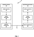
- FIG. 1 is a block diagram illustrating an example video coding system 10 that may utilize the techniques of this disclosure.
- video coder refers generically to both video encoders and video decoders.
- video coding or “coding” may refer generically to video encoding or video decoding.
- video coding system 10 includes a source device 12 and a destination device 14.
- Source device 12 generates encoded video data. Accordingly, source device 12 may be referred to as a video encoding device or a video encoding apparatus.
- Destination device 14 may decode the encoded video data generated by source device 12. Accordingly, destination device 14 may be referred to as a video decoding device or a video decoding apparatus.
- Source device 12 and destination device 14 may be examples of video coding devices or video coding apparatuses.
- Source device 12 and destination device 14 may comprise a wide range of devices, including desktop computers, mobile computing devices, notebook (e.g., laptop) computers, tablet computers, set-top boxes, telephone handsets such as so-called “smart" phones, televisions, cameras, display devices, digital media players, video gaming consoles, in-car computers, or the like.
- desktop computers mobile computing devices
- notebook (e.g., laptop) computers tablet computers
- set-top boxes telephone handsets such as so-called “smart" phones
- televisions cameras
- display devices digital media players
- video gaming consoles in-car computers, or the like.
- Destination device 14 may receive encoded video data from source device 12 via a channel 16.
- Channel 16 may comprise one or more media or devices capable of moving the encoded video data from source device 12 to destination device 14.
- channel 16 may comprise one or more communication media that enable source device 12 to transmit encoded video data directly to destination device 14 in real-time.
- source device 12 may modulate the encoded video data according to a communication standard, such as a wireless communication protocol, and may transmit the modulated video data to destination device 14.
- the one or more communication media may include wireless and/or wired communication media, such as a radio frequency (RF) spectrum or one or more physical transmission lines.
- RF radio frequency
- the one or more communication media may form part of a packet-based network, such as a local area network, a wide-area network, or a global network (e.g., the Internet).
- the one or more communication media may include routers, switches, base stations, or other equipment that facilitate communication from source device 12 to destination device 14.
- channel 16 may include a storage medium that stores encoded video data generated by source device 12.
- destination device 14 may access the storage medium, e.g., via disk access or card access.
- the storage medium may include a variety of locally-accessed data storage media such as Blu-ray discs, DVDs, CD-ROMs, flash memory, or other suitable digital storage media for storing encoded video data.
- channel 16 may include a file server or another intermediate storage device that stores encoded video data generated by source device 12.
- destination device 14 may access encoded video data stored at the file server or other intermediate storage device (e.g., via streaming or download).
- the file server may be a type of server capable of storing encoded video data and transmitting the encoded video data to destination device 14.
- Example file servers include web servers (e.g., for a website), file transfer protocol (FTP) servers, network attached storage (NAS) devices, and local disk drives.
- FTP file transfer protocol
- NAS network attached storage
- Destination device 14 may access the encoded video data through a standard data connection, such as an Internet connection.
- a standard data connection such as an Internet connection.
- Example types of data connections may include wireless channels (e.g., Wi-Fi connections), wired connections (e.g., DSL, cable modem, etc.), or combinations of both that are suitable for accessing encoded video data stored on a file server.
- the transmission of encoded video data from the file server may be a streaming transmission, a download transmission, or a combination of both.
- video coding system 10 may be configured to support one-way or two-way video transmission to support applications such as video streaming, video playback, video broadcasting, and/or video telephony.
- FIG. 1 is merely an example and the techniques of this disclosure may apply to video coding settings (e.g., video encoding or video decoding) that do not necessarily include any data communication between the encoding and decoding devices.
- data is retrieved from a local memory, streamed over a network, or the like.
- a video encoding device may encode and store data (e.g., video data) to memory, and/or a video decoding device may retrieve and decode data (e.g., video data) from memory.
- the encoding and decoding is performed by devices that do not communicate with one another, but simply encode data to memory and/or retrieve and decode data from memory.
- source device 12 includes a video source 18, a video encoder 20, and an output interface 22.
- output interface 22 may include a modulator/demodulator (modem) and/or a transmitter.
- Video source 18 may include a video capture device, e.g., a video camera, a video archive containing previously-captured video data, a video feed interface to receive video data from a video content provider, and/or a computer graphics system for generating video data, or a combination of such sources of video data.
- Video encoder 20 may encode video data from video source 18.
- source device 12 directly transmits the encoded video data to destination device 14 via output interface 22.
- the encoded video data may also be stored onto a storage medium or a file server for later access by destination device 14 for decoding and/or playback.
- destination device 14 includes an input interface 28, a video decoder 30, and a display device 32.
- input interface 28 includes a receiver and/or a modem.
- Input interface 28 may receive encoded video data over channel 16.
- Display device 32 may be integrated with or may be external to destination device 14. In general, display device 32 displays decoded video data.
- Display device 32 may comprise a variety of display devices, such as a liquid crystal display (LCD), a plasma display, an organic light emitting diode (OLED) display, or another type of display device.
- LCD liquid crystal display
- OLED organic light emitting diode
- Video encoder 20 and video decoder 30 each may be implemented as any of a variety of suitable circuitry, such as one or more microprocessors, digital signal processors (DSPs), application-specific integrated circuits (ASICs), field-programmable gate arrays (FPGAs), discrete logic, hardware, or any combinations thereof. If the techniques are implemented partially in software, a device may store instructions for the software in a suitable, non-transitory computer-readable storage medium and may execute the instructions in hardware using one or more processors to perform the techniques of this disclosure. Any of the foregoing (including hardware, software, a combination of hardware and software, etc.) may be considered to be one or more processors. Each of video encoder 20 and video decoder 30 may be included in one or more encoders or decoders, either of which may be integrated as part of a combined encoder/decoder (CODEC) in a respective device.
- CODEC combined encoder/decoder
- This disclosure may generally refer to video encoder 20 "signalling" certain information to another device, such as video decoder 30.
- the term “signalling” may generally refer to the communication of syntax elements and/or other data used to decode the compressed video data. Such communication may occur in real- or near-real-time. Alternately, such communication may occur over a span of time, such as might occur when storing syntax elements to a computer-readable storage medium in an encoded bitstream at the time of encoding, which then may be retrieved by a decoding device at any time after being stored to this medium.
- video encoder 20 and video decoder 30 operate according to a video compression standard, such as ISO/IEC MPEG-4 Visual and ITU-T H.264 (also known as ISO/IEC MPEG-4 AVC), including its Scalable Video Coding (SVC) extension, Multiview Video Coding (MVC) extension, and MVC-based 3DV extension.
- SVC Scalable Video Coding
- MVC Multiview Video Coding
- MVC-based 3DV extension any bitstream conforming to MVC-based 3DV always contains a sub-bitstream that is compliant to a MVC profile, e.g., stereo high profile.
- 3DV three-dimensional video
- video encoder 20 and video decoder 30 may operate according to ITU-T H.261, ISO/IEC MPEG-1 Visual, ITU-T H.262 or ISO/IEC MPEG-2 Visual, and ITU-T H.264, ISO/IEC Visual.
- video encoder 20 and video decoder 30 may operate according to the High Efficiency Video Coding (HEVC) standard developed by the Joint Collaboration Team on Video Coding (JCT-VC) of ITU-T Video Coding Experts Group (VCEG) and ISO/IEC Motion Picture Experts Group (MPEG).
- HEVC Working Draft 10 referred to as "HEVC Working Draft 10” or "HEVC WD10”
- JCT-VC Joint Collaboration Team on Video Coding
- HEVC Working Draft 10 is available from http://phenix.int-evry.fr/jct/doc_end_user/documents/13_Incheon/wg11/JCTVC-M0432-v3.zip.
- the 3DV extension of HEVC may be referred to as HEVC-based 3DV, HEVC-3DV, or 3D-HEVC.
- the multiview extension to HEVC namely MV-HEVC, is also being developed by the Joint Collaborative Team on 3D Video Coding Extension Development (JCT-3V).
- MV-HEVC WD4 A recent Working Draft (WD) of MV-HEVC, referred to hereinafter as MV-HEVC WD4, is described in Tech et al., "MV-HEVC Draft Text 4," Joint Collaborative Team on Video Coding (JCT-VC) of ITU-T SG16 WP3 and ISO/IEC JTC1/SC29/WG11, 4th Meeting, Incheon, KR, April 2013, document no. JCT3V-D1004_d0 (hereinafter, "JCT3V-D1004_d0").
- JCT3V-D1004_d0 Joint Collaborative Team on Video Coding
- JCT3V-D1004_d0 is available from available from http://phenix.it-sudparis.eu/jct2/doc_end_user/documents/4_Incheon/wg11/JCT3V-D1004-v1.zip.
- SHVC The scalable extension to HEVC, named SHVC, is also being developed by the JCT-VC.
- a recent Working Draft (WD) of SHVC is referred to as SHVC WD2 hereinafter and is described in Chen et al, "SHVC Working Draft 2," Joint Collaborative Team on Video Coding (JCT-VC) of ITU-T SG16 WP3 and ISO/IEC JTC1/SC29/WG11, 13th Meeting, Incheon, KR, 18-26 April 2013, document no. JCTVC-M1008_v1 (hereinafter, "JCTVC-M1008_v1").
- JCTVC-M1008_v1 Joint Collaborative Team on Video Coding
- JCTVC-M1008_v1 is available from http://phenix.int-evry.fr/jct/doc_end_user/documents/13_Incheon/wg11/JCTVC-M1008-v1.zip.
- a video sequence typically includes a series of pictures. Pictures may also be referred to as "frames.”
- a picture may include three sample arrays, denoted S L , S Cb and S Cr .
- S L is a two-dimensional array (i.e., a block) of luma samples.
- S Cb is a two-dimensional array of Cb chrominance samples.
- S Cr is a two-dimensional array of Cr chrominance samples.
- Chrominance samples may also be referred to herein as "chroma" samples.
- a picture may be monochrome and may only include an array of luma samples.
- video encoder 20 may generate a set of coding tree units (CTUs).
- Each of the CTUs may comprise (e.g., be) a coding tree block of luma samples, two corresponding coding tree blocks of chroma samples, and syntax structures used to code the samples of the coding tree blocks.
- a CTU may comprise a single coding tree block and syntax structures used to code the samples of the coding tree block.
- a coding tree block may be an NxN block of samples.
- a CTU may also be referred to as a "tree block” or a "largest coding unit” (LCU).
- the CTUs of HEVC may be broadly analogous to the macroblocks of other standards, such as H.264/AVC.
- a CTU is not necessarily limited to a particular size and may include one or more coding units (CUs).
- a slice may include an integer number of CTUs ordered consecutively in a scanning order (e.g., the raster scan order).
- video unit or “video block” or “block” to refer to one or more sample blocks and syntax structures used to code samples of the one or more blocks of samples.
- Example types of video units may include CTUs, CUs, PUs, transform units (TUs), macroblocks, macroblock partitions, and so on.
- discussion of CTUs, CU, PUs, etc. may be interchanged with discussion of macroblocks or macroblock partitions.
- video encoder 20 may recursively perform quad-tree partitioning on the coding tree blocks of a CTU to divide the coding tree blocks into coding blocks, hence the name "coding tree units.”
- a coding block may be an NxN block of samples.
- a CU may comprise (e.g., be) a coding block of luma samples and two corresponding coding blocks of chroma samples of a picture that has a luma sample array, a Cb sample array and a Cr sample array, and syntax structures used to code the samples of the coding blocks.
- a CU may comprise a single coding block and syntax structures used to code the samples of the coding block.
- Video encoder 20 may partition a coding block of a CU into one or more prediction blocks.
- a prediction block may be a rectangular (i.e., square or non-square) block of samples on which the same prediction is applied.
- a prediction unit (PU) of a CU may comprise (e.g., be) a prediction block of luma samples, two corresponding prediction blocks of chroma samples of a picture, and syntax structures used to predict the prediction block samples.
- Video encoder 20 may generate predictive luma, Cb and Cr blocks for luma, Cb and Cr prediction blocks of each PU of the CU.
- a PU may comprise a single prediction block and syntax structures used to predict the prediction block samples.
- Video encoder 20 may use intra prediction or inter prediction to generate the predictive blocks for a PU. If video encoder 20 uses intra prediction to generate the predictive blocks of a PU, video encoder 20 may generate the predictive blocks of the PU based on decoded samples of the picture associated with the PU (i.e., the picture containing the prediction block of the PU).
- video encoder 20 may generate the predictive blocks of the PU based on decoded samples of one or more pictures other than the picture associated with the PU.
- Video encoder 20 may use uni-prediction or bi-prediction to generate the predictive blocks of a PU.
- uni-prediction to generate the predictive blocks for a PU
- the PU may have a single motion vector.
- video encoder 20 uses bi-prediction to generate the predictive blocks for a PU, the PU may have two motion vectors.
- video encoder 20 may generate a first reference picture list (RefPicListO) and a second reference picture list (RefPicList1) for a current slice.
- Each of the reference picture lists may include one or more reference pictures.
- video encoder 20 may search the reference pictures in either or both RefPicListO and RefPicList1 to determine a reference location within a reference picture.
- video encoder 20 may generate, based at least in part on samples corresponding to the reference location, the predictive blocks (i.e., predictive sample blocks) for the PU.
- video encoder 20 may generate a single motion vector that indicates a spatial displacement between a prediction block of the PU and the reference location.
- a motion vector may include a horizontal component specifying a horizontal displacement between the prediction block of the PU and the reference location and may include a vertical component specifying a vertical displacement between the prediction block of the PU and the reference location.
- video encoder 20 may determine a first reference location in a reference picture in RefPicListO and a second reference location in a reference picture in RefPicList1. Video encoder 20 may then generate, based at least in part on samples corresponding to the first and second reference locations, the predictive blocks for the PU. Moreover, when using bi-prediction to encode the PU, video encoder 20 may generate a first motion vector indicating a spatial displacement between a prediction block of the PU and the first reference location and a second motion vector indicating a spatial displacement between the prediction block of the PU and the second reference location.
- video encoder 20 may generate one or more residual blocks for the CU. For example, video encoder 20 may generate a luma residual block for the CU. Each sample in the CU's luma residual block indicates a difference between a luma sample in one of the CU's predictive luma blocks and a corresponding sample in the CU's original luma coding block. In addition, video encoder 20 may generate a Cb residual block for the CU.
- predictive blocks e.g., luma, Cb and Cr predictive blocks
- Each sample in the CU's Cb residual block may indicate a difference between a Cb sample in one of the CU's predictive Cb blocks and a corresponding sample in the CU's original Cb coding block.
- Video encoder 20 may also generate a Cr residual block for the CU.
- Each sample in the CU's Cr residual block may indicate a difference between a Cr sample in one of the CU's predictive Cr blocks and a corresponding sample in the CU's original Cr coding block.
- video encoder 20 may use quad-tree partitioning to decompose the residual blocks (e.g., luma, Cb and Cr residual blocks) of a CU into one or more transform blocks (e.g., luma, Cb and Cr transform blocks).
- a transform block may be a rectangular block of samples on which the same transform is applied.
- a transform unit (TU) of a CU may comprise (e.g., be) a transform block of luma samples, two corresponding transform blocks of chroma samples, and syntax structures used to transform the transform block samples.
- each TU of a CU may have (i.e., be associated with) a luma transform block, a Cb transform block, and a Cr transform block.
- the luma transform block of (i.e., associated with) the TU may be a sub-block of the CU's luma residual block.
- the Cb transform block may be a sub-block of the CU's Cb residual block.
- the Cr transform block may be a sub-block of the CU's Cr residual block.
- a TU may comprise a single transform block of samples and syntax structures used to transform the transform block samples.
- Video encoder 20 may apply one or more transforms to a transform block of a TU to generate a coefficient block for the TU.
- a coefficient block may be a two-dimensional array of transform coefficients.
- a transform coefficient may be a scalar quantity.
- video encoder 20 may apply one or more transforms to a luma transform block of a TU to generate a luma coefficient block for the TU.
- Video encoder 20 may apply one or more transforms to a Cb transform block of a TU to generate a Cb coefficient block for the TU.
- Video encoder 20 may apply one or more transforms to a Cr transform block of a TU to generate a Cr coefficient block for the TU.
- video encoder 20 may quantize the coefficient block. Quantization generally refers to a process in which transform coefficients are quantized to possibly reduce the amount of data used to represent the transform coefficients, providing further compression.
- video encoder 20 may entropy encode syntax elements indicating the quantized transform coefficients. For example, video encoder 20 may perform Context-Adaptive Binary Arithmetic Coding (CABAC) on the syntax elements indicating the quantized transform coefficients.
- CABAC Context-Adaptive Binary Arithmetic Coding
- Video encoder 20 may output the entropy-encoded syntax elements in a bitstream.
- CABAC Context-Adaptive Binary Arithmetic Coding
- Video encoder 20 may output a bitstream that includes the entropy-encoded syntax elements.
- the bitstream may include a sequence of bits that forms a representation of coded pictures and associated data.
- the bitstream may comprise a sequence of network abstraction layer (NAL) units.
- NAL network abstraction layer
- Each of the NAL units may include a NAL unit header and may encapsulate a raw byte sequence payload (RBSP).
- the NAL unit header may include a syntax element that indicates a NAL unit type code.
- the NAL unit type code specified by the NAL unit header of a NAL unit indicates the type of the NAL unit.
- a RBSP may be a syntax structure containing an integer number of bytes that is encapsulated within a NAL unit. In some instances, an RBSP includes zero bits.
- NAL units may encapsulate different types of RBSPs.
- a first type of NAL unit may encapsulate an RBSP for a picture parameter set (PPS)
- a second type of NAL unit may encapsulate an RBSP for a coded slice
- a third type of NAL unit may encapsulate an RBSP for Supplemental Enhancement Information (SEI), and so on.
- NAL units that encapsulate RBSPs for video coding data (as opposed to RBSPs for parameter sets and SEI messages) may be referred to as video coding layer (VCL) NAL units.
- VCL video coding layer
- SEI contains information that is not necessary to decode the samples of coded pictures from VCL NAL units.
- an SEI RBSP may contain one or more SEI messages.
- An SEI message may be a message that contains SEI.
- a video parameter set is a syntax structure comprising syntax elements that apply to zero or more entire coded video sequences (CVSs).
- a sequence parameter set may contain information that applies to all slices of a CVS.
- An SPS may include a syntax element that identifies a VPS that is active when the SPS is active.
- the syntax elements of a VPS may be more generally applicable than the syntax elements of an SPS.
- a PPS is a syntax structure comprising syntax elements that apply to zero or more coded pictures.
- a PPS may include a syntax element that identifies an SPS that is active when the PPS is active.
- a slice header of a slice may include a syntax element that indicates a PPS that is active when the slice is being coded.
- Video decoder 30 may receive a bitstream generated by video encoder 20.
- video decoder 30 may parse the bitstream to obtain (e.g., decode) syntax elements from the bitstream.
- Video decoder 30 may reconstruct the pictures of the video data based at least in part on the syntax elements obtained (e.g., decoded) from the bitstream.
- the process to reconstruct the video data may be generally reciprocal to the process performed by video encoder 20. For instance, video decoder 30 may use motion vectors of PUs to determine predictive blocks for the PUs of a current CU. In addition, video decoder 30 may inverse quantize transform coefficient blocks associated with TUs of the current CU.
- Video decoder 30 may perform inverse transforms on the transform coefficient blocks to reconstruct transform blocks of (i.e., associated with) the TUs of the current CU. Video decoder 30 may reconstruct the coding blocks of the current CU by adding the samples of the predictive blocks for PUs of the current CU to corresponding samples of the transform blocks of the TUs of the current CU. By reconstructing the coding blocks for each CU of a picture, video decoder 30 may reconstruct the picture.
- the video coder may determine five reference picture set (RPS) subsets for the current picture: RefPicSetStCurrBefore, RefPicSetStCurrAfter, RefPicSetFoll, RefPicSetLtCurr, and RefPicSetLtFoll.
- RPS reference picture set
- the union of these five RPS subsets for the current picture may be referred to herein as the RPS for the current picture.
- RefPicSetStCurrBefore may include short-term reference pictures that occur before the current picture in output order and may be used for reference by the current picture.
- RefPicStCurrAfter may include short-term reference pictures that occur after the current picture in output order and may be used for reference by the current picture.
- RefPicSetStFoll may include short-term reference pictures that are not used for reference by the current picture.
- RefPicSetLtCurr may include long-term reference pictures that may be used for reference by the current picture.
- RefPicSetLtFoll may include long-term reference pictures that are not used for reference by the current picture.
- HEVC and other video coding standards provide for several different slice types. These slice types include I slices, P slices, and B slices. In I slices, only intra prediction is allowed. In P slices, intra prediction and uni-directional inter prediction is allowed. In B slices, intra prediction, uni-directional inter prediction, and bi-directional inter prediction is allowed.
- the video coder may initialize a first reference picture list (i.e., List 0). Furthermore, if the current slice is a B slice, the video coder may initialize a second reference picture list (i.e., List 1). This disclosure may refer to List 0 as "RefPicListO" and may refer to List 1 as "RefPicList1.”
- a video coder may generate an initial version of RefPicListO.
- RefPicSetStCurrBefore are listed first, followed by reference pictures in RefPicSetStCurrAfter, followed by reference pictures in RefPicSetLtCurr, if available.
- RefPicListO short-term pictures with earlier output order (i.e., reference pictures in RefPicSetStCurrBefore) are firstly inserted into RefPicListO in ascending order of picture order count (POC) distance to the current picture, then short-term pictures with later output order (i.e., reference pictures in RefPicSetStCurrAfter) are inserted into RefPicListO in ascending order of POC distance to the current picture, and finally the long-term pictures (i.e., reference pictures in RefPicSetLtCurr) are inserted at the end.
- a POC distance is the difference between POC values for pictures.
- a POC is a variable that is associated with each picture that indicates the position of the associated picture in output order relative to the output order positions of the other pictures in the same coded video sequence.
- the video coder may generate an initial version of RefPicList1.
- RefPicSetStCurrAfter reference pictures in RefPicSetStCurrAfter are listed first, followed by reference pictures in RefPictSetStCurrBefore, followed by reference pictures in RefPicSetLtCurr.
- RefPicList1 short-term pictures with later output order (i.e., reference pictures in RefPicSetStCurrAfter) are firstly inserted into RefPicList1 in ascending order of POC distance to the current picture, then short-term pictures with earlier output order (i.e., reference pictures in RefPicSetStCurrBefore) are inserted into RefPicList1 in ascending order of POC distance to the current picture, and finally the long-term pictures (i.e., reference pictures in RefPicSetLtCurr) are inserted at the end.
- short-term pictures with later output order i.e., reference pictures in RefPicSetStCurrAfter
- short-term pictures with earlier output order i.e., reference pictures in RefPicSetStCurrBefore
- the long-term pictures i.e., reference pictures in RefPicSetLtCurr
- reference picture list initialization creates default List 0 and List 1 (if the slice is a B slice) based on three RPS subsets: RefPicSetStCurrBefore, RefPicSetStCurrAfter, and RefPicSetLtCurr.
- the video coder may modify the order of reference pictures in the reference picture list. That is, the video coder may perform a reference picture list modification (RPLM) process to modify the order of the reference pictures in the reference picture list.
- RPLM reference picture list modification
- a “view component” may be a coded representation of a view in a single access unit.
- a “view” may refer to a sequence of view components associated with the same view identifier.
- Multi-view coding supports inter-view prediction.
- Inter-view prediction is similar to the inter prediction used in HEVC and may use the same syntax elements.
- video encoder 20 may use, as a reference picture, a picture that is in the same access unit as the current video unit, but in a different view.
- conventional inter prediction only uses pictures in different access units as reference pictures.
- a view may be referred to as a "base view” if a video decoder (e.g., video decoder 30) can decode pictures in the view without reference to pictures in any other view.
- a video coder (such as video encoder 20 or video decoder 30) may add a picture into a reference picture list if the picture is in a different view but within a same time instance (i.e., access unit) as the picture that the video coder is currently coding.
- the video coder may insert an inter-view prediction reference picture at any position of a reference picture list.
- NAL units may include headers and payloads.
- the headers of NAL units may include nuh_reserved_zero_6bits syntax elements.
- the nuh_reserved_zero_6bits syntax element of a NAL unit is equal to 0 if the NAL unit relates to a base layer in multi-view coding, 3DV coding, or scalable video coding. Data in a base layer of a bitstream may be decoded without reference to data in any other layer of the bitstream. If the NAL unit does not relate to a base layer in multi-view coding, 3DV, or scalable video coding, the nuh_reserved_zero_6bits syntax element may have a non-zero value.
- the nuh_reserved_zero_6bits syntax element of the NAL unit specify a layer identifier of the NAL unit.
- NAL units encapsulating data of certain pictures of a layer may be removed from the bitstream without affecting the decodability of other pictures in the layer.
- pictures with even picture order count (POC) values may be decodable without reference to pictures with odd POC values. Removing NAL units encapsulating data of such pictures may reduce the frame rate of the bitstream.
- a subset of pictures within a layer that may be decoded without reference to other pictures within the layer may be referred to herein as a sub-layer.
- NAL units may include temporal_id syntax elements.
- the temporal_id syntax element of a NAL unit specifies a temporal identifier of the NAL unit. If the temporal identifier of a first NAL unit is less than the temporal identifier of a second NAL unit in the same layer, the data encapsulated by the first NAL unit may be decoded without reference to the data encapsulated by the second NAL unit.
- Each operation point of a bitstream is associated with a set of layer identifiers (i.e., a set of nuh_layer_id values) and a temporal identifier.
- the set of layer identifiers may be denoted as OpLayerIdSet and the temporal identifier may be denoted as TemporalID. If a NAL unit's layer identifier is in an operation point's set of layer identifiers and the NAL unit's temporal identifier is less than or equal to the operation point's temporal identifier, the NAL unit belongs to the operation point.
- An operation point is a bitstream subset that is associated with an OpLayerIdSet and a temporal identifier.
- the operation point may include each NAL unit that is associated with the operation point.
- the operation point does not include VCL NAL units that are not associated with the operation point.
- At least some video coding standards specify video buffering models.
- a buffering model is referred to as a "hypothetical reference decoder" or "HRD.”
- HRD hyper reference decoder
- the HRD describes how data is to be buffered for decoding and how decoded data is buffered for output.
- the HRD describes the operation of a coded picture buffer ("CPB"), a decoded picture buffer (“DPB”), and a video decoding process.
- the CPB is a first-in first-out buffer containing access units in a decoding order specified by HRD.
- the DPB is a buffer holding decoded pictures for reference, output reordering, or output delay specified by the HRD.
- the behaviors of the CPB and DPB may be mathematically specified.
- the HRD may directly impose constraints on timing, buffer sizes, and bit rates. Furthermore, the HRD may indirectly impose constraints on various bitstream characteristics and statistics.
- bitstream conformance and decoder conformance are specified as parts of the HRD specification.
- the HRD model specifies tests to determine whether a bitstream conforms to a standard and tests to determine whether a decoder conforms to the standard.
- the HRD is named as some kind of decoder, video encoders typically use the HRD to guarantee bitstream conformance, while video decoders typically do not need the HRD.
- H.264/AVC and HEVC both specify two types of bitstream or HRD conformance, namely Type I and Type II.
- a Type I bitstream is a NAL unit stream containing only the VCL NAL units and filler data NAL unit for all access units in the bitstream.
- a NAL unit stream is a sequence of NAL units.
- a Type II bitstream is a NAL unit stream that contains, in addition to the VCL NAL units and filler data NAL units for all access units in the bitstream, at least one of the following: additional non-VCL NAL units other than filler data NAL units; and all leading_zero_8bits, zero_byte, start_coded_prefix_one_3bytes, and trailing_zero_8bits syntax elements that form a byte stream from the NAL unit stream.
- the device may select an operation point of the bitstream.
- the device may then determine a set of HRD parameters applicable to the selected operation point.
- the device may use the set of HRD parameters applicable to the selected operation point to configure the behavior of the HRD. More particularly, the device may use the applicable set of HRD parameters to configure the behaviors of particular components of the HRD, such as a hypothetical stream scheduler (HSS), the CPB, a decoding process, the DPB, and so on.
- HSS hypothetical stream scheduler
- the CPB the CPB
- a decoding process the DPB
- the HSS may inject coded video data of the bitstream into the CPB of the HRD according to a particular schedule.
- the device may invoke a decoding process that decodes the coded video data in the CPB.
- the decoding process may output decoded pictures to the DPB.
- the device may determine whether a particular set of constraints remains satisfied. For example, the device may determine whether an overflow or underflow condition occurs in the CPB or DPB while the HRD is decoding the operation point of the selected operation point.
- the device may select and process each operation point of the bitstream in this manner. If no operation point of the bitstream causes the constraints to be violated, the device may determine that the bitstream conforms to the video coding standard.
- Both H.264/AVC and HEVC specify two types of decoder conformance, namely output timing decoder conformance and output order decoder conformance.
- a decoder claiming conformance to a specific profile, tier and level is able to successfully decode all bitstreams that conform to the bitstream conformance requirements of a video coding standard, such as HEVC.
- a “profile” may refer to a subset of the bitstream syntax.
- "Tiers” and "levels" may be specified within each profile.
- a level of a tier may be a specified set of constraints imposed on values of the syntax elements in the bitstream. These constraints may be simple limits on values.
- the constraints may take the form of constraints on arithmetic combinations of values (e.g., picture width multiplied by picture height multiplied by number of pictures decoded per second).
- a level specified for a lower tier is more constrained than a level specified for a higher tier.
- the device may provide, to both the HRD and the DUT, a bitstream that conforms to the video coding standard.
- the HRD may process the bitstream in the manner described above with regard to the bitstream conformance test.
- the device may determine that the DUT conforms to the video coding standard if the order of decoded pictures output by the DUT matches the order of decoded pictures output by the HRD.
- the device may determine that the DUT conforms to the video coding standard if the timing with which the DUT outputs decoded pictures matches the timing with which the HRD outputs the decoded pictures.
- decoding or CPB removal may be access unit based. That is, the HRD is assumed to decode complete access units at one time and remove complete access units from the CPB. Furthermore, in the H.264/AVC and HEVC HRD models, it is assumed that picture decoding is instantaneous.
- Video encoder 20 may signal, in picture timing SEI messages, decoding times to start decoding of access units. In practical applications, if a conforming video decoder strictly follows the decoding times signalled to start decoding of access units, the earliest possible time to output a particular decoded picture is equal to the decoding time of that particular picture plus the time needed for decoding that particular picture. However, in the real world, the time needed for decoding a picture cannot be equal to zero.
- HRD parameters may control various aspects of the HRD. In other words, the HRD may rely on the HRD parameters.
- the HRD parameters may include an initial CPB removal delay, a CPB size, a bit rate, an initial DPB output delay, and a DPB size.
- Video encoder 20 may signal these HRD parameters in a hrd_parameters( ) syntax structure specified in a video parameter set (VPS) and/or a sequence parameter set (SPS). Individual VPS's and/or SPS's may include multiple hrd_parameters( ) syntax structures for different sets of HRD parameters.
- video encoder 20 may signal HRD parameters in buffering period SEI messages or picture timing SEI messages.
- an operation point of a bitstream is associated with a set of layer identifiers (i.e., a set of nuh_reserved_zero_6bits values) and a temporal identifier.
- An operation point may include each NAL unit that is associated with the operation point.
- An operation point may have a different frame rate and/or bit rate than an original bitstream. This is because the operation point may not include some pictures and/or some of the data of the original bitstream.
- video encoder 20 may signal different sets of HRD parameters for different operation points.
- video encoder 20 may include, in a VPS, multiple hrd_parameters( ) syntax structures that include HRD parameters for different operation points.
- the set of HRD parameters optionally includes a set of information that is common for all temporal sub-layers.
- the set of HRD parameters may optionally include a set of common syntax elements that are applicable to operation points that include any temporal sub-layers.
- a temporal sub-layer may be a temporal scalable layer of a temporal scalable bitstream consisting of VCL NAL units with a particular value of TemporalId and the associated non-VCL NAL units.
- the sets of HRD parameters may include a set of syntax elements that are specific to individual temporal sub-layer representations.
- the hrd_parameters( ) syntax structure may optionally include a set of information that is common for all sub-layer representations and always includes sub-layer-specific information. Because the set of common information is common to multiple sets of HRD parameters, it may be unnecessary to signal the set of common information in multiple sets of HRD parameters. Rather, in HEVC Working Draft 10, the common information may be present in a set of HRD parameters when the set of HRD parameters is the first set of HRD parameters in a VPS or the common information may be present in a set of HRD parameters when the set of HRD parameters is associated with a first operation point index.
- HEVC Working Draft 10 supports the presence of common information when either the hrd_parameters ( ) syntax structure is the first hrd_parameters( ) syntax structure in the VPS or when the hrd_parameters( ) syntax structure is associated with a first operation point index.
- Table 1 is an example syntax structure for a hrd_parameters( ) syntax structure in HEVC.
- syntax elements with type descriptor ue(v) may be variable-length unsigned integers encoded using 0 th order exponential Golomb (Exp-Golomb) coding with left bit first.
- syntax elements having descriptors of the form u( n ), where n is a non-negative integer are unsigned values of length n.
- nal_hrd_parameters_present_flag 1 specifies that NAL HRD parameters (pertaining to Type II bitstream conformance) are present in the hrd_parameters( ) syntax structure.
- nal_hrd_parameters_present_flag 0 specifies that NAL HRD parameters are not present in the hrd_parameters( ) syntax structure.
- NAL HRD parameters are HRD parameters pertaining to Type II bitstream conformance.
- the syntax element nal_hrd_parameters_present_flag 1 specifies that VCL HRD parameters (pertaining to all bitstream conformance) are present in the hrd_parameters( ) syntax structure.
- VCL HRD parameters are HRD parameters pertaining to all bitstream conformance.
- the syntax elements in the "if ( commonInfPresentFlag) ⁇ ... ⁇ " block are the common information of the HRD parameter sets.
- the common information of the set of HRD parameters may include the syntax elements timing_info_present_flag, num_units_in_tick, time_scale, nal_hrd_parameters_present_flag, vcl_hrd_parameters_present_flag, sub_pic_cpb_params_present_flag, tick_divisor_minus2, du_cpb_removal_delay_length_minus1, bit_rate_scale, cpb_size_scale, initial_cpb_removal_delay_length_minus 1, cpb_removal_delay_length_minus 1, and dpb_output_delay_length_minus1.
- the syntax elements fixed_pic_rate_flag[i], pic_duration_in_tc_minus1[i], low_delay_hrd_flag[i], and cpb_cnt_minus1[i] may be a set of sub-layer-specific HRD parameters.
- these syntax elements of the hrd_parameters() syntax structure may only be applicable to operation points that include a specific sub-layer representation.
- the HRD parameters of a hrd_parameters() syntax structure may include, in addition to the optionally-included common information, a set of sub-layer-specific HRD parameters that is specific to a particular sub-layer representation of the bitstream.
- the fixed_pic_rate_flag[i] syntax element may indicate that, when HighestTid is equal to i, the temporal distance between the HRD output times of any two consecutive pictures in output order is constrained in a specific way.
- HighestTid may be a variable that identifies a highest temporal sub-layer (e.g., of an operation point).
- the pic_duration_in_tc_minus1[i] syntax element may specify, when HighestTid is equal to i, the temporal distance, in clock ticks, between the HRD output times of any consecutive pictures in output order in the coded video sequence.
- the low_delay_hrd_flag[i] syntax element may specify the HRD operation mode, when HighestTid is equal to i, as specified in Annex C of HEVC Working Draft 10.
- the cpb_cnt_minus1[i] syntax element may specify the number of alternative CPB specifications in the bitstream of the coded video sequence when HighestTid is equal to i, wherein one alternative CPB specification refers to one particular CPB operation with a particular set of CPB parameters.
- Video encoder 20 may use SEI messages to include, in the bitstream, metadata that is not required for correct decoding of the sample values of pictures.
- video decoder 30 or other devices may use the metadata included in SEI messages for various other purposes.
- video decoder 30 or another device may use the metadata in SEI messages for picture output timing, picture displaying, loss detection, and error concealment.
- Video encoder 20 may include one or more SEI NAL units in an access unit. In other words, any number of SEI NAL units may be associated with an access unit. Furthermore, each SEI NAL unit may contain one or more SEI messages.
- the HEVC standard describes the syntax and semantics for various types of SEI messages. However, the HEVC standard does not describe the handling of the SEI messages because the SEI messages do not affect the normative decoding process. One reason to have SEI messages in the HEVC standard is to enable supplemental data being interpreted identically in different systems using HEVC. Specifications and systems using HEVC may require video encoders to generate certain SEI messages or may define specific handling of particular types of received SEI messages. Table 2, below, lists SEI messages specified in HEVC and briefly describes their purposes.
- Progressive refinement segment Indicates that certain consecutive pictures represent a progressive refinement of the quality of a picture rather than a moving scene
- Film grain characteristics Enables decoders to synthesize film grain
- Post-filter hint Provides suggested post-filter coefficients or correlation information for post-filter design Tone mapping information Remapping to another color space than that used or assumed in encoding Frame packing arrangement
- Decoded picture hash Checksum of the decoded picture, which may be used for error detection
- Decoding unit information timing Sub-picture removal time for HRD operation
- Active parameter sets Provides information on active VPS, SPS, etc. Structure of Pictures description Describes the temporal and inter prediction structure of the bitstream
- each NAL unit includes a syntax element (e.g., nal_unit_type) that indicates a NAL unit type of the NAL unit.
- video decoder 30 may identify, based on the NAL unit type of a NAL unit, the NAL unit as being associated with one of a plurality of picture types.
- picture types may include Instantaneous Decoding Refresh (IDR) pictures, Clean Random Access (CRA) pictures, Temporal Sub-Layer Access (TSA) pictures, Broken Link Access (BLA) pictures and coded pictures that are not IDR, CRA, or TSA pictures.
- the definition of an IDR picture in HEVC may be similar to the definition of an IDR picture in H.264/AVC.
- the definition of a coded picture in HEVC may be similar to the definition of a coded picture in H.264/AVC.
- the IDR and the coded pictures may be picture types inherited from the H.264/AVC specification.
- An IDR picture may cause a decoding process to mark all reference pictures as "unused for reference.” Because reference pictures marked as "unused for reference” may be removed from a decoded picture buffer (DPB) that stores the reference pictures, an IDR picture may clean out the DPB.
- DPB decoded picture buffer
- All coded pictures that follow an IDR picture in decoding order can be decoded without inter prediction from any picture that precedes the IDR picture in decoding order.
- the first picture of each coded video sequence in decoding order is an IDR picture or a BLA picture, or a CRA picture that is the also the first picture of the bitstream.
- the access unit may be referred to as an IDR access unit.
- a coded video sequence is a sequence of access units that consists, in decoding order, of an IDR access unit followed by zero or more access units that are not IRAP access units with NoRaslOutputFlag equal to 1 including all subsequent access units up to but not including any subsequent IDR access unit.
- the CRA and TSA picture types are new in HEVC and are not available in the H.264/AVC specification.
- the CRA picture type facilitates decoding that begins from any random access point (RAP) in the middle of a video sequence. Inserting CRA pictures in a video sequence may be more efficient than inserting IDR pictures into the same video sequence. Random access is the act of starting a decoding process for a bitstream at a point other than the beginning of the bitstream.
- a bitstream starting from a CRA picture may be a conforming bitstream. That is, the portion of a bitstream that starts with a CRA picture may conform to the HEVC specification.
- a TSA picture can be used to indicate a valid temporal sub-layer switching point.
- IDR pictures may be used in both H.264/AVC and HEVC as random access pictures.
- the IDR picture specified in both H.264/AVC and HEVC can be used for random access.
- an IDR picture starts a coded video sequence and may always clean the DPB, pictures following the IDR picture in decoding order cannot use pictures decoded prior, in decoding order, to the IDR picture for reference.
- bitstreams relying on IDR pictures for random access may have significantly lower coding efficiency (e.g., 6% lower coding efficiency).
- a CRA picture in HEVC may allow pictures that follow the CRA picture in decoding order, but precede the CRA picture in output order, to use pictures decoded before the CRA for reference.
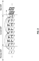
- FIG. 2 is a conceptual diagram illustrating a CRA picture and leading pictures. That is, a typical prediction structure around a CRA picture is shown in the example of FIG. 2 .
- each parallelogram represents a picture. Numbers within each respective parallelogram indicate example POC values of the respective picture represented by the respective parallelogram.
- the CRA picture i.e., the picture in the example of FIG. 2 with POC value 24
- GEP Group of Pictures
- Video decoder 30 may correctly decode the leading pictures of a current CRA picture if the decoding starts from an IDR picture or a CRA picture that occurs in decoding order before the current CRA picture. However, video decoder 30 may not be able to correctly decode the leading pictures of a current CRA picture when random access from the current CRA picture occurs. Hence, video decoder 30 may discard the leading pictures of a current CRA picture during random access decoding from the current CRA picture.
- Error propagation may occur when video decoder 30 uses an incorrectly decoded portion of a reference picture when decoding a current picture.
- no picture in the GOP that follows a CRA picture may use as reference any picture that precedes the CRA picture in either decoding order or output order (including leading pictures of the CRA picture).
- all pictures in the next GOP that follow the CRA picture both in decoding order and output order shall not use any picture that precedes the CRA picture either in decoding order or output order as reference.
- Recovery point SEI messages may be used in H.264/AVC to provide random access in a manner similar to the CRA pictures in HEVC.
- H.264/AVC supports similar random access functionalities with a recovery point SEI message.
- An H.264/AVC decoder implementation may or may not support the recovery point SEI message functionality.
- a bitstream starting with a CRA picture is considered to be a conforming bitstream.
- the leading pictures of the CRA picture may refer to unavailable reference pictures and hence cannot be correctly decoded.
- HEVC specifies that the leading pictures of a starting CRA picture are not output, hence the name "clean random access.”
- HEVC may specify a decoding process to generate unavailable reference pictures for decoding of the non-output leading pictures.
- conforming decoder implementations do not have to follow that decoding process, as long as the decoder implementations can generate identical output compared to when the decoding process is performed from the beginning of the bitstream.
- a conforming bitstream may include no IDR pictures at all.
- JCTVC-M0266_v2 Joint Collaborative Team on Video Coding (JCT-VC) of ITU-T SG 16 and ISO/IEC JTC 1/SC 29/WG 11, 13th Meeting, Incheon, KR, April 2013, document JCTVC-M0266_v2 (hereinafter, "JCTVC-M0266_v2"), provided a design for definition of the decoding process for cross-layer random access skipped (CL-RAS) pictures.
- JCTVC-M0266_v2 is available from http://phenix.int-evry. fr/jct/doc_end_user/documents/13_Incheon/wg11/JCTVC-M0266-v2 .zip.
- JCTVC-M0266_v2 defines IRAP access units (AUs) to include all AUs that have an IRAP picture with nuh_layer_id equal to 0.
- the nuh_layer_id value of a picture may indicate a layer to which the picture belongs.
- the design in JCTVC-M0266_v2 also defines CL-RAS pictures and broken-link IDR (BL-IDR) pictures that are used to detail the process of decoding of a bitstream starting from such an IRAP access unit.
- an access unit A set of NAL units that are associated with each other according to a specified classification rule, are consecutive in decoding order, and contain all coded pictures associated with the same output time. NOTE 1 - In addition to containing the VCL NAL units of the coded pictures, an access unit may also contain non-VCL NAL units.
- coded video sequence CVS: A sequence of access units that consists, in decoding order, of an initial IRAP access unit , followed by zero or more access units that are not initial IRAP access units , including all subsequent access units up to but not including any subsequent access unit that is an initial IRAP access unit .
- cross-layer random access skipped (CL-RAS) picture A coded picture for which each VCL NAL unit has nal_unit_type equal to CL_RAS_R or CL_RAS_N.
- NoClrasOutputFlag is equal to 1
- the CL-RAS picture is not output and may not be correctly decodable, as the CL-RAS picture may contain references to pictures that are not present in the bitstream.
- CL-RAS pictures are not used as reference pictures for the decoding process of non-CL-RAS pictures.
- initial intra random access point (IRAP) access unit An IRAP access unit in which the coded picture with nuh_layer_id equal to 0 has NoRaslOutputFlag equal to 1.
- IDR picture An IRAP picture for which each VCL NAL unit has nal_unit_type equal to IDR_W_RADL, IDR_N_LP , BL IDR W RADL, or BL IDR N LP.
- intra random access point (IRAP) access unit An access unit in which the coded picture with nuh layer id equal to 0 is an IRAP picture.
- a random access skipped leading (RASL) picture is a coded picture for which each VCL NAL unit has nal_unit_type equal to RASL_R or RASL_N.
- All RASL pictures are leading pictures of an associated BLA or CRA picture.
- the associated IRAP picture has NoRaslOutputFlag equal to 1
- the RASL picture is not output and may not be correctly decodable, as the RASL picture may contain references to pictures that are not present in the bitstream.
- RASL pictures are not used as reference pictures for the decoding process of non-RASL pictures. When present, all RASL pictures precede, in decoding order, all trailing pictures of the same associated IRAP picture.
- NoRaslOutputFlag is defined for each IRAP picture.
- NoRaslOutputFlag is equal to 1
- the IRAP picture starts a new coded video sequence, and the associated RASL pictures, when present, are not output.
- JCTVC-M0266v2 the definition of NoRaslOutputFlag is changed as follows:
- the current picture is an IRAP picture, the following applies: [Note that this definition of NoRaslOutputFlag is the same as in JCT3V-C1004v4.zip, but moved to be applicable also to IRAP pictures with nuh_layer_id greater than 0.]
- NoClrasOutputFlag may be defined as follows:
- the decoding process may be defined such that unavailable reference pictures are generated (similar to the generation of unavailable reference pictures in HEVC WD10) when decoding a CL-RAS picture of an initial IRAP access unit (AU) and when NoClRasOutputFlag is equal to 1.
- a bitstream does not include coded CL-RAS pictures.
- some HRD operations may rely on the bitstream including coded CL-RAS pictures. For instance, in HRD operations as specified in Annex C of HEVC Working Draft 10, access units containing RASL pictures may need to be taken into consideration in derivation of CPB arrival and removal times. Accordingly, a video decoder may perform a process to generate such unavailable reference pictures. The video coder may set each sample value of each pixel in a generated unavailable reference picture to a maximum value. For instance, as described in section 8.3.3.2 of HEVC Working Draft 10: When this process is invoked, an unavailable picture is generated as follows:
- U.S. Provisional Patent Application 61/812,225 filed April 16, 2013 , is related to one or more techniques of this disclosure.
- random access points are defined as those access units where all pictures in the access unit are IRAP pictures. This imposes restrictions on the random access capability, and it may be desirable to also provide random access capability at those access units where the pictures with nuh_layer_id equal to 0 are IRAP pictures.
- U.S. Provisional Patent Application 61/812,225 defined the notions of CL-RAS pictures that are associated with IRAP access units containing an IRAP picture with nuh layer id equal to 0.
- streaming servers and media-aware network elements may decide not to send CL-RAS pictures to receivers when such CL-RAS pictures are not correctly decodable (i.e. when NoClrasOutputFlag is equal to 1 for the initial IRAP AU).
- the bitstreams of both cases need to be defined as conforming bitstreams and consequently two sets of HRD parameters are needed. Otherwise, only one case can be defined as conforming bitstreams and consequently enhancements to conforming decoders are needed to handle the other case for which the bitstreams are non-conforming bitstreams.
- a device e.g., a video decoder or other device
- the NoClrasPicPresentFlag is a variable that can be set e.g., by external means or in an SEI message.
- the device may set the value (e.g., NoClRasPicPresentFlag) based at least in part on data in an SEI message of the video data bitstream.
- the value e.g., NoClRasPicPresentFlag
- the device may perform, based at least in part on the value (e.g., NoClRasPicPresentFlag), a CPB operation.
- video encoder 20 may generate a bitstream that includes a sequence of bits that forms a representation of coded pictures and associated data.
- the bitstream may include syntax elements from which a device that receives the bitstream is able to derive a value (e.g., NoClRasPicPresentFlag) that specifies whether cross-layer random access skipped (CL-RAS) pictures of an Intra Random Access Point (IRAP) access unit are present in the bitstream.
- Video encoder 20 may output the bitstream.
- video encoder 20 may generate an SEI message that sets a variable that specifies whether CL-RAS pictures of an IRAP access unit are present in a bitstream that includes a sequence of bits that forms a representation of coded pictures and associated data.
- the device may include the SEI message in the bitstream.
- some techniques of this disclosure define conformance of bitstreams where CL-RAS pictures associated with an initial IRAP access unit that has an IRAP picture with nuh layer id equal to 0 and NoRaslOutputFlag equal to 1. Syntax elements in a buffering period SEI message that correspond to CPB and DPB delay offsets when the CL-RAS pictures are not present in the conformance bitstream are signalled. Furthermore, some techniques of this disclosure define syntax elements in a buffering period SEI message that correspond to an alternate CPB initial removal delay and offsets values to account for removal of CL-RAS pictures. Additionally, some techniques of this disclosure define CPB and DPB behaviors using the newly defined syntax elements when the CL-RAS pictures are not present in the conforming bitstream.
- some techniques of this disclosure define a complete generation process for unavailable reference pictures when decoding a CL-RAS picture in an initial IRAP AU and when NoClRasOutputFlag is equal to 1. For instance, when CL-RAS pictures are not output (e.g., when NoClRasOutputFlag is equal to 1) and the current picture is a CL-RAS picture in an initial IRAP access unit, a video decoder (e.g., video decoder 30) may generate unavailable reference pictures for the CL-RAS picture.
- an IRAP access unit is an access unit where the picture with nuh_layer_id equal to 0 is an IRAP picture.
- An initial IRAP access unit may be an IRAP access unit where the IRAP picture with nuh_layer_id equal to 0 has NoRaslOutputFlag equal to 1.
- some techniques of this disclosure define a new cross-layer HRD parameters SEI message that is used to signal alternate bit rate and CPB size parameters for IRAP access units. These parameters may be used when the corresponding IRAP access unit is an initial IRAP access unit with associated CL-RAS pictures not present.
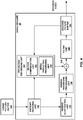
- FIG. 3 is a block diagram illustrating an example video encoder 20 that may implement the techniques of this disclosure.
- FIG. 3 is provided for purposes of explanation and should not be considered limiting of the techniques as broadly exemplified and described in this disclosure.
- this disclosure describes video encoder 20 in the context of HEVC coding.
- the techniques of this disclosure may be applicable to other coding standards or methods.
- video encoder 20 includes a prediction processing unit 100, a residual generation unit 102, a transform processing unit 104, a quantization unit 106, an inverse quantization unit 108, an inverse transform processing unit 110, a reconstruction unit 112, a filter unit 114, a decoded picture buffer 116, and an entropy encoding unit 118.
- Prediction processing unit 100 includes an inter-prediction processing unit 120 and an intra-prediction processing unit 126.
- Inter-prediction processing unit 120 includes a motion estimation unit 122 and a motion compensation unit 124.
- video encoder 20 may include more, fewer, or different functional components.
- Video encoder 20 may receive video data. Video encoder 20 may encode each CTU in a slice of a picture of the video data. Each of the CTUs may be associated with equally-sized luma coding tree blocks (CTBs) and corresponding CTBs of the picture. As part of encoding a CTU, prediction processing unit 100 may perform quad-tree partitioning to divide the CTBs of the CTU into progressively-smaller blocks. The smaller blocks may be coding blocks of CUs. For example, prediction processing unit 100 may partition a CTB associated with a CTU into four equally-sized sub-blocks, partition one or more of the sub-blocks into four equally-sized sub-sub-blocks, and so on.
- CTBs luma coding tree blocks
- Video encoder 20 may encode CUs of a CTU to generate encoded representations of the CUs (i.e., coded CUs).
- prediction processing unit 100 may partition the coding blocks associated with the CU among one or more PUs of the CU.
- each PU may be associated with a luma prediction block and corresponding chroma prediction blocks.
- Video encoder 20 and video decoder 30 may support PUs having various sizes.
- the size of a CU may refer to the size of the luma coding block of the CU and the size of a PU may refer to the size of a luma prediction block of the PU.
- video encoder 20 and video decoder 30 may support PU sizes of 2Nx2N or NxN for intra prediction, and symmetric PU sizes of 2Nx2N, 2NxN, Nx2N, NxN, or similar for inter prediction.
- Video encoder 20 and video decoder 30 may also support asymmetric partitioning for PU sizes of 2NxnU, 2NxnD, nLx2N, and nRx2N for inter prediction.
- Inter-prediction processing unit 120 may generate predictive data for a PU by performing inter prediction on each PU of a CU.
- the predictive data for the PU may include predictive blocks of the PU and motion information for the PU.
- Inter-prediction processing unit 120 may perform different operations for a PU of a CU depending on whether the PU is in an I slice, a P slice, or a B slice. In an I slice, all PUs are intra predicted. Hence, if the PU is in an I slice, inter-prediction processing unit 120 does not perform inter prediction on the PU.
- the predictive block is formed using spatial prediction from previously-encoded neighboring blocks within the same frame.
- motion estimation unit 122 may search the reference pictures in a list of reference pictures (e.g., "RefPicListO") for a reference region for the PU.
- the reference region for the PU may be a region, within a reference picture, that contains sample blocks that most closely correspond to the sample blocks of the PU.
- Motion estimation unit 122 may generate a reference index that indicates a position in RefPicListO of the reference picture containing the reference region for the PU.
- motion estimation unit 122 may generate a motion vector that indicates a spatial displacement between a coding block of the PU and a reference location associated with the reference region.
- the motion vector may be a two-dimensional vector that provides an offset from the coordinates in the current picture to coordinates in a reference picture.
- Motion estimation unit 122 may output the reference index and the motion vector as the motion information of the PU.
- Motion compensation unit 124 may generate the predictive blocks of the PU based on actual or interpolated samples at the reference location indicated by the motion vector of the PU.
- motion estimation unit 122 may perform uni-prediction or bi-prediction for the PU. To perform uni-prediction for the PU, motion estimation unit 122 may search the reference pictures of RefPicListO or a second reference picture list ("RefPicList1") for a reference region for the PU.
- RefPicListO a second reference picture list
- Motion estimation unit 122 may output, as the motion information of the PU, a reference index that indicates a position in RefPicListO or RefPicList1 of the reference picture that contains the reference region, a motion vector that indicates a spatial displacement between a prediction block of the PU and a reference location associated with the reference region, and one or more prediction direction indicators that indicate whether the reference picture is in RefPicListO or RefPicList1.
- Motion compensation unit 124 may generate the predictive blocks of the PU based at least in part on actual or interpolated samples at the reference region indicated by the motion vector of the PU.
- motion estimation unit 122 may search the reference pictures in RefPicListO for a reference region for the PU and may also search the reference pictures in RefPicList1 for another reference region for the PU.
- Motion estimation unit 122 may generate reference indexes that indicate positions in RefPicListO and RefPicList1 of the reference pictures that contain the reference regions.
- motion estimation unit 122 may generate motion vectors that indicate spatial displacements between the reference locations associated with the reference regions and a prediction block of the PU.
- the motion information of the PU may include the reference indexes and the motion vectors of the PU.
- Motion compensation unit 124 may generate the predictive blocks of the PU based at least in part on actual or interpolated samples at the reference region indicated by the motion vector of the PU.
- Intra-prediction processing unit 126 may generate predictive data for a PU by performing intra prediction on the PU.
- the predictive data for the PU may include predictive blocks for the PU and various syntax elements.
- Intra-prediction processing unit 126 may perform intra prediction on PUs in I slices, P slices, and B slices.
- intra-prediction processing unit 126 may use multiple intra prediction modes to generate multiple sets of predictive data for the PU.
- the neighboring PUs may be above, above and to the right, above and to the left, or to the left of the PU, assuming a left-to-right, top-to-bottom encoding order for PUs, CUs, and CTUs.
- Intra-prediction processing unit 126 may use various numbers of intra prediction modes, e.g., 33 directional intra prediction modes. In some examples, the number of intra prediction modes may depend on the size of the prediction blocks of the PU.
- Prediction processing unit 100 may select the predictive data for PUs of a CU from among the predictive data generated by inter-prediction processing unit 120 for the PUs or the predictive data generated by intra-prediction processing unit 126 for the PUs. In some examples, prediction processing unit 100 selects the predictive data for the PUs of the CU based on rate/distortion metrics of the sets of predictive data. The predictive blocks of the selected predictive data may be referred to herein as the selected predictive blocks.
- Residual generation unit 102 may generate, based on the coding blocks (e.g., luma, Cb and Cr coding blocks) of a CU and the selected predictive blocks (e.g., luma, Cb and Cr predictive blocks) of the PUs of the CU, residual blocks (e.g., luma, Cb and Cr residual blocks) of the CU. For instance, residual generation unit 102 may generate the residual blocks of the CU such that each sample in the residual blocks has a value equal to a difference between a sample in a coding block of the CU and a corresponding sample in a corresponding selected predictive block of a PU of the CU.
- residual blocks e.g., luma, Cb and Cr residual blocks
- Transform processing unit 104 may perform quad-tree partitioning to partition the residual blocks of a CU into transform blocks of (i.e., associated with) TUs of the CU.
- a TU may have (i.e., be associated with) a luma transform block and two corresponding chroma transform blocks.
- the sizes and positions of the luma and chroma transform blocks of TUs of a CU may or may not be based on the sizes and positions of prediction blocks of the PUs of the CU.
- a quad-tree structure known as a "residual quad-tree" (RQT) may include nodes associated with (e.g., corresponding to) each of the regions.
- the TUs of a CU may correspond to leaf nodes of the RQT.
- Transform processing unit 104 may generate transform coefficient blocks for each TU of a CU by applying one or more transforms to the transform blocks of the TU. Transform processing unit 104 may apply various transforms to a transform block associated with a TU. For example, transform processing unit 104 may apply a discrete cosine transform (DCT), a directional transform, or a conceptually-similar transform to a transform block. In some examples, transform processing unit 104 does not apply transforms to a transform block. In such examples, the transform block may be treated as a transform coefficient block.
- DCT discrete cosine transform
- Quantization unit 106 may quantize the transform coefficients in a coefficient block. The quantization process may reduce the bit depth associated with some or all of the transform coefficients. For example, an n-bit transform coefficient may be rounded down to an m-bit transform coefficient during quantization, where n is greater than m.
- Quantization unit 106 may quantize a coefficient block associated with a TU of a CU based on a quantization parameter (QP) value associated with the CU.
- QP quantization parameter
- Video encoder 20 may adjust the degree of quantization applied to the coefficient blocks associated with a CU by adjusting the QP value associated with the CU. Quantization may introduce loss of information, thus quantized transform coefficients may have lower precision than the original ones.
- Inverse quantization unit 108 and inverse transform processing unit 110 may apply inverse quantization and inverse transforms to a coefficient block, respectively, to reconstruct a residual block from the coefficient block.
- Reconstruction unit 112 may add the reconstructed residual block to corresponding samples from one or more predictive blocks generated by prediction processing unit 100 to produce a reconstructed transform block associated with a TU. By reconstructing transform blocks for each TU of a CU in this way, video encoder 20 may reconstruct the coding blocks of the CU.
- Filter unit 114 may perform one or more deblocking operations to reduce blocking artifacts in the coding blocks associated with a CU.
- Decoded picture buffer 116 may store the reconstructed coding blocks after filter unit 114 performs the one or more deblocking operations on the reconstructed coding blocks.
- Inter-prediction processing unit 120 may use a reference picture that contains the reconstructed coding blocks to perform inter prediction on PUs of other pictures.
- intra-prediction processing unit 126 may use reconstructed coding blocks in decoded picture buffer 116 to perform intra prediction on other PUs in the same picture as the CU.
- Entropy encoding unit 118 may receive data from other functional components of video encoder 20. For example, entropy encoding unit 118 may receive coefficient blocks from quantization unit 106 and may receive syntax elements from prediction processing unit 100. Entropy encoding unit 118 may perform one or more entropy encoding operations on the data to generate entropy-encoded data.
- entropy encoding unit 118 may perform a context-adaptive variable length coding (CAVLC) operation, a CABAC operation, a variable-to-variable (V2V) length coding operation, a syntax-based context-adaptive binary arithmetic coding (SBAC) operation, a Probability Interval Partitioning Entropy (PIPE) coding operation, an Exponential-Golomb encoding operation, or another type of entropy encoding operation on the data.
- Video encoder 20 may output a bitstream that includes entropy-encoded data generated by entropy encoding unit 118.
- the bitstream may include data that represents a RQT for a CU.
- the bitstream generated by video encoder 20 of FIG. 3 may include one or more syntax elements from which a device that receives the bitstream (e.g. video decoder 30) is able to derive a value that specifies whether CL-RAS pictures of an IRAP access unit are present in the bitstream.
- a buffering period SEI message generated by video encoder 20 may include one or more syntax elements from which a device that receives the bitstream is able to derive a value that specifies whether CL-RAS pictures of an IRAP access unit are present in the bitstream.
- FIG. 4 is a block diagram illustrating an example video decoder 30 that is configured to implement the techniques of this disclosure.
- FIG. 4 is provided for purposes of explanation and is not limiting on the techniques as broadly exemplified and described in this disclosure.
- this disclosure describes video decoder 30 in the context of HEVC coding.
- the techniques of this disclosure may be applicable to other coding standards or methods.
- video decoder 30 includes an entropy decoding unit 150, a prediction processing unit 152, an inverse quantization unit 154, an inverse transform processing unit 156, a reconstruction unit 158, a filter unit 160, and a decoded picture buffer 162.
- Prediction processing unit 152 includes a motion compensation unit 164 and an intra-prediction processing unit 166.
- video decoder 30 may include more, fewer, or different functional components.
- a coded picture buffer (CPB) 151 may receive and store encoded video data (e.g., NAL units) of a bitstream.
- Entropy decoding unit 150 may receive NAL units from CPB 151 and may parse the NAL units to obtain (e.g., decode) syntax elements.
- Entropy decoding unit 150 may entropy decode entropy-encoded syntax elements in the NAL units.
- Prediction processing unit 152, inverse quantization unit 154, inverse transform processing unit 156, reconstruction unit 158, and filter unit 160 may generate decoded video data based on the syntax elements extracted from the bitstream.
- the NAL units of the bitstream may include coded slice NAL units.
- entropy decoding unit 150 may extract and entropy decode syntax elements from the coded slice NAL units.
- Each of the coded slices may include a slice header and slice data.
- the slice header may contain syntax elements pertaining to a slice.
- the syntax elements in the slice header may include a syntax element that identifies a PPS associated with a picture that contains the slice.
- one or more components of video decoder 30 may determine a value (e.g., NoClRasPicPresentFlag). Furthermore, in accordance with one or more techniques of this disclosure, video decoder 30 may determine, based on the value, whether all CL-RAS pictures of an IRAP access unit are present in a video data bitstream. In addition, the device may decode the video data bitstream.
- a value e.g., NoClRasPicPresentFlag
- video decoder 30 may perform a reconstruction operation on a CU. To perform the reconstruction operation on a CU, video decoder 30 may perform a reconstruction operation on each TU of the CU. By performing the reconstruction operation for each TU of the CU, video decoder 30 may reconstruct residual blocks of the CU.
- inverse quantization unit 154 may inverse quantize, i.e., de-quantize, coefficient blocks of (e.g., associated with) the TU.
- Inverse quantization unit 154 may use a QP value associated with the CU of the TU to determine a degree of quantization and, likewise, a degree of inverse quantization for inverse quantization unit 154 to apply. That is, the compression ratio, i.e., the ratio of the number of bits used to represent original sequence and the compressed one, may be controlled by adjusting the value of the QP used when quantizing transform coefficients.
- the compression ratio may also depend on the method of entropy coding employed.
- inverse transform processing unit 156 may apply one or more inverse transforms to the coefficient block in order to generate a residual block associated with the TU.
- inverse transform processing unit 156 may apply an inverse DCT, an inverse integer transform, an inverse Karhunen-Loeve transform (KLT), an inverse rotational transform, an inverse directional transform, or another inverse transform to the coefficient block.
- KLT Karhunen-Loeve transform
- intra-prediction processing unit 166 may perform intra prediction to generate predictive blocks for the PU.
- Intra-prediction processing unit 166 may use an intra prediction mode to generate the predictive luma, Cb and Cr blocks for the PU based on the prediction blocks of spatially-neighboring PUs.
- Intra-prediction processing unit 166 may determine the intra prediction mode for the PU based on one or more syntax elements decoded from the bitstream.
- Prediction processing unit 152 may construct a first reference picture list (RefPicListO) and a second reference picture list (RefPicList1) based on syntax elements extracted from the bitstream. Furthermore, if a PU is encoded using inter prediction, entropy decoding unit 150 may extract motion information for the PU. Motion compensation unit 164 may determine, based on the motion information of the PU, one or more reference regions for the PU. Motion compensation unit 164 may generate, based on sample blocks at the one or more reference blocks for the PU, predictive luma, Cb and Cr blocks for the PU.
- Reconstruction unit 158 may use the transform blocks (e.g., luma, Cb and Cr transform blocks) associated with TUs of a CU and the predictive blocks (e.g., luma, Cb and Cr predictive blocks) of the PUs of the CU, i.e., either intra-prediction data or inter-prediction data, as applicable, to reconstruct the coding blocks (e.g., luma, Cb and Cr coding blocks) of the CU.
- the transform blocks e.g., luma, Cb and Cr transform blocks
- the predictive blocks e.g., luma, Cb and Cr predictive blocks
- reconstruction unit 158 may add samples of the transform blocks (e.g., luma, Cb and Cr transform blocks) to corresponding samples of the predictive blocks (e.g., luma, Cb and Cr predictive blocks) to reconstruct the coding blocks (e.g., luma, Cb and Cr coding blocks) of the CU.
- transform blocks e.g., luma, Cb and Cr transform blocks
- predictive blocks e.g., luma, Cb and Cr predictive blocks
- Filter unit 160 may perform a deblocking operation to reduce blocking artifacts associated with the coding blocks (e.g., luma, Cb and Cr coding blocks) of the CU.
- Video decoder 30 may store the coding blocks (e.g., luma, Cb and Cr coding blocks) of the CU in decoded picture buffer 162.
- Decoded picture buffer 162 may provide reference pictures for subsequent motion compensation, intra prediction, and presentation on a display device, such as display device 32 of FIG. 1 .
- video decoder 30 may perform, based on the blocks (e.g., luma, Cb and Cr blocks) in decoded picture buffer 162, intra prediction or inter prediction operations on PUs of other CUs.
- video decoder 30 may extract, from the bitstream, transform coefficient levels of coefficient blocks, inverse quantize the transform coefficient levels, apply a transform to the transform coefficient levels to generate transform blocks, generate, based at least in part on the transform blocks, one or more coding blocks, and output the one or more coding block for display.
- changes to syntax, semantics and decoding processes required for defining the conformance with the use of CL-RAS pictures are defined relative to particular processes described in JCTVC-M0266v2 and U.S. Provisional Patent Application 61/812,225 .
- the syntax elements introduced for the HRD parameters are included in the buffering period SEI message.
- associated CL-RAS pictures CL-RAS pictures for an initial IRAP AU where the CL-RAS pictures within a CVS with layer ID value nuh_layer_id contained in layerSetLayerIdList that succeed the first picture in an initial IRAP AU and precede, in decoding order, an IRAP picture with layer ID value nuh_layer_id.
- the following changes may be made to the general decoding process described in HEVC Working Draft 10.
- the SHVC and MV-HEVC working drafts define some portions of SHVC and MV-HEVC in terms of changes relative to the HEVC Working Draft (e.g., HEVC Working Draft 10).
- passages marked with underlining are additional changes to the syntax, semantics and decoding process of HEVC Working Draft 10 introduced by JCTVC-M0266v2 to implement SHVC and/or MV-HEVC. Passages marked with bold italics are additional changes introduced by the current disclosure.
- Input to this process is a bitstream.
- Output of this process is a list of decoded pictures.
- the layer identifier list TargetDecLayerIdList which specifies the list of nuh_layer_id values, in increasing order of nuh_layer_id values, of the NAL units to be decoded, is specified as follows:
- the sub-bitstream extraction process as specified in clause 10 is applied with the bitstream, HighestTid, and TargetDecLayerIdList as inputs, and the output is assigned to a bitstream referred to as BitstreamToDecode.
- the number of sample arrays of the current picture is as follows:
- the decoding process for the current picture takes as inputs the syntax elements and upper-case variables from clause 7.
- the term "the bitstream" (or part thereof, e.g. a CVS of the bitstream) refers to BitstreamToDecode (or part thereof).
- the decoding process is specified such that all decoders will produce numerically identical cropped decoded pictures. Any decoding process that produces identical cropped decoded pictures to those produced by the process described herein (with the correct output order or output timing, as specified) conforms to the decoding process requirements of this Specification.
- the access unit containing the current picture is an initial IRAP access unit, the following applies:
- NoClrasPicPresentFlag 0 specifies that all the CL-RAS pictures associated with the initial IRAP AU are not present in the bitstream.
- NoClrasPicPresentFlag 1 specifies that all the CL-RAS pictures that are associated with the initial IRAP AU are present in the bitstream.
- NoClRasPicPresentFlag may be derived by the syntax elements present as part of the bitstream, e.g. by new NAL unit type values, or through a flag in the VPS, through flags in an SEI message, e.g. in the buffering period SEI message.
- bitstream conformance it is a requirement of bitstream conformance that the following restriction is followed: If the current picture is an IRAP picture with nuh_layer_id greater than 0, then for every direct reference layer of the current layer with layer ID value directRefLayerId, there exists at least one IRAP picture in the CVS with nuh_layer_id value equal to directRefLayerId and with a decoding order preceding the current picture.
- a video decoder may perform a bitstream conformance test to determine whether the video data bitstream conforms to a video coding specification, wherein it is a requirement of bitstream conformance that if a current picture is an IRAP picture with a layer identifier greater than 0, then for each direct reference layer of a current layer, there exists at least one IRAP picture in a CVS with a layer identifier equal to a layer identifier of the current layer and with a decoding order preceding the current picture.
- a device may generate a bitstream that includes a VPS that includes a syntax element (e.g., a flag) from which a video decoder is able to derive the NoClRasPicPresentFlag.
- a syntax element e.g., a flag
- nal_unit_type specifies the type of RBSP data structure contained in the NAL unit as specified in Table 7-1.
- NOTE 1 - NAL unit types in the range of UNSPEC48..UNSPEC63 may be used as determined by the application. No decoding process for these values of nal_unit_type is specified in this Specification. Since different applications might use these NAL unit types for different purposes, particular care must be exercised in the design of encoders that generate NAL units with these nal_unit_type values, and in the design of decoders that interpret the content of NAL units with these nal_unit_type values.
- decoders For purposes other than determining the amount of data in the decoding units of the bitstream (as specified in Annex C), decoders shall ignore (remove from the bitstream and discard) the contents of all NAL units that use reserved values of nal_unit_type. NOTE 2 - This requirement allows future definition of compatible extensions to this Specification.
- NAL unit type codes and NAL unit type classes nal_unit_type Name of nal_unit_type Content of NAL unit and RBSP syntax structure
- NAL unit type class 0 TRAIL_N Coded slice segment of a non-TSA, non-STSA trailing picture
- VCL 1 TRAIL_R slice_segment_ layer_rbsp( ) 2
- VCL 3 TSA_R slice_segment_ layer_rbsp( ) 4
- VCL 7 RADL_R slice_segment_ layer_rbsp( ) 8
- VCL 9 RASL_R slice_seg
- VCL NAL unit types VCL RSV_VCL31 32 VPS_NUT Video parameter set video_parameter_set_rbsp( ) non-VCL 33 SPS_NUT Sequence parameter set seq_parameter_set_ rbsp( ) non-VCL 34 PPS_NUT Picture parameter set pic_parameter_set_rbsp( ) non-VCL 35 AUD_NUT Access unit delimiter access_unit_delimiter_rbsp( ) non-VCL 36 EOS_NUT End of sequence end_of_seq_rbsp( ) non-VCL 37 EOB_NUT End of bitstream end_of_bitstream_rbsp( ) non-VCL 38 FD_NUT Filler data filler_data_rbsp( ) non-VCL 39 PREFIX_SEI_NUT Supplemental enhancement information non-VCL 40 SUFFIX_SEI_NUT sei_rbsp() 41..47
- RSV_NVCL47 Reserved non-VCL 48..63 UNSPEC48.. UNSPEC63 Unspecified non-VCL
- NOTE 3 A CRA picture may have associated RASL or RADL pictures present in the bitstream.
- NOTE 4 A BLA picture having nal_unit_type equal to BLA_W_LP may have associated RASL or RADL pictures present in the bitstream.
- a BLA picture having nal_unit_type equal to BLA_W_RADL does not have associated RASL pictures present in the bitstream, but may have associated RADL pictures in the bitstream.
- a BLA picture having nal_unit_type equal to BLA_N_LP does not have associated leading pictures present in the bitstream.
- An IDR picture having nal_unit_type equal to IDR_N_LP or BL_IDR_N_LP does not have associated leading pictures present in the bitstream.
- An IDR picture having nal unit type equal to IDR_W_RADL or BL_IDR_W_RADL does not have associated RASL pictures present in the bitstream, but may have associated RADL pictures in the bitstream.
- All coded slice segment NAL units with a particular value of nuh_layer_id in an access unit shall have the same value of nal_unit_type.
- a picture is also referred to as having a nal_unit_type equal to the nal_unit_type of the coded slice segment NAL units of the picture.
- nal_unit_type equal to TRAIL_N, TSA_N, STSA_N, RADL_N, RASL_N, CL_RAS_N, RSV_VCL_N12, or RSV_VCL_N14
- the picture is a sub-layer non-reference picture. Otherwise, the picture is a sub-layer reference picture.
- the current access unit is an initial IRAP access unit, the following applies:
- each picture other than the first picture in the bitstream in decoding order, is considered to be associated with the previous IRAP picture in decoding order.
- a picture When a picture is a leading picture, it shall be a RADL or RASL picture.
- a picture When a picture is a trailing picture, it shall not be a RADL or RASL picture.
- a picture When a picture is a leading picture, it shall precede, in decoding order, all trailing pictures that are associated with the same IRAP picture.
- No RASL pictures shall be present in the bitstream that are associated with a BLA picture having nal_unit_type equal to BLA_W_RADL or BLA_N_LP. No RASL pictures shall be present in the bitstream that are associated with an IDR picture.
- No RADL pictures shall be present in the bitstream that are associated with a BLA picture having nal_unit_type equal to BLA_N_LP or that are associated with an IDR picture having nal_unit_type equal to IDR_N_LP or BL_IDR_N_LP.
- NOTE 7 It is possible to perform random access at the position of an IRAP access unit by discarding all access units before the IRAP access unit (and to correctly decode the IRAP picture and all the subsequent non-RASL pictures in decoding order), provided each parameter set is available (either in the bitstream or by external means not specified in this Specification) when it needs to be activated.
- Any picture that has PicOutputFlag equal to 1 that precedes an IRAP picture in decoding order shall precede the IRAP picture in output order and shall precede any RADL picture associated with the IRAP picture in output order.
- Any RASL picture associated with a CRA or BLA picture shall precede any RADL picture associated with the CRA or BLA picture in output order.
- Any RASL picture associated with a CRA picture shall follow, in output order, any IRAP picture that precedes the CRA picture in decoding order.
- nal_unit_type shall be equal to TSA_R, TSA_N, RADL_R, RADL_N, RASL_R, or RASL_N.
- nuh_layer_id specifies the identifier of the layer.
- nuh_layer_id When_nal_unit_type is equal to CL_RAS_R, CL_RAS_N, BL_IDR_W_RADL, or BL_IDR_N_LP, the value of nuh_layer_id shall be greater than 0.
- Each PPS RBSP is initially considered not active for any layer with nuh_layer_id greater than 0 at the start of the operation of the decoding process. At most one PPS RBSP is considered active for each non-zero nuh_layer_id value at any given moment during the operation of the decoding process, and the activation of any particular PPS RBSP for a particular non-zero nuh_layer_id value results in the deactivation of the previously-active PPS RBSP for that non-zero nuh_layer_id value (if any).
- a PPS RBSP (with a particular value of pps_pic_parameter_set_id) is not active for a nuh_layer_id value and it is referred to by a coded slice segment NAL unit (using a value of slice_pic_parameter_set_id equal to the pps_pic_parameter_set_id and having that value of nuh_layer_id), it is activated for that nuh layer id value.
- This PPS RBSP is called the active layer PPS RBSP for that nuh layer_id value until it is deactivated by the activation of another PPS RBSP for the same layer.
- a PPS RBSP with that particular value of pps_pic_parameter_set_id, shall be available to the decoding process prior to its activation, included in at least one access unit with TemporalId less than or equal to the TemporalId of the PPS NAL unit or provided through external means.
- the nuh layer_id value of the NAL unit containing the PPS RBSP that is activated for nuh_layer_id equal to nuhLayerIdA shall be less than or equal to nuhLayerIdA.
- the same PPS RBSP may be the active layer PPS for more than one nuh_layer_id value.
- Any PPS NAL unit containing the value of pps_pic_parameter_set_id for the active layer PPS RBSP for a coded picture shall have the same content as that of the active layer PPS RBSP for the coded picture, unless it follows the last VCL NAL unit of the coded picture and precedes the first VCL NAL unit of another coded picture.
- Each SPS RBSP is initially considered not active for any layer with nuh_layer_id greater than 0 at the start of the operation of the decoding process. At most one SPS RBSP is considered active for each non-zero nuh_layer_id value at any given moment during the operation of the decoding process, and the activation of any particular SPS RBSP for a particular non-zero nuh_layer_id value results in the deactivation of the previously-active SPS RBSP for that non-zero nuh_layer_id value (if any).
- an SPS RBSP (with a particular value of sps_seq_parameter_set_id) is not already active for a nuh layer id value and it is referred to by activation of a PPS RBSP for that nuh layer id value (in which pps_seq_parameter_set_id is equal to the sps_seq_parameter_set_id value), it is activated for that nuh_layer_id value.
- This SPS RBSP is called the active layer SPS RBSP for that nuh_layer_ id value until it is deactivated by the activation of another SPS RBSP for the same layer.
- An SPS RBSP with that particular value of sps_seq_parameter_set_id shall be available to the decoding process prior to its activation, included in at least one access unit with TemporalId equal to 0 or provided through external means.
- An activated SPS RBSP for a particular nuh_layer_id value shall remain active for a sequence of pictures in decoding order with that nuh_layer_id value starting from a picture having that nuh_layer_id value in either an initial IRAP access unit or the first access unit after the initial IRAP access unit that contains a picture with nuh_layer_id value, inclusive, until either the next picture having that nuh_layer_id value in an initial IRAP access unit , exclusive, or the end of the CVS, whichever is earlier.
- nuh_layer_id value the NAL unit containing the SPS RBSP that is activated for nuh_layer_id equal to nuhLayerIdA shall be less than or equal to nuhLayerIdA.
- the same SPS RBSP may be the active layer SPS for more than one nuh_layer_id value.
- Any SPS NAL unit containing the value of sps_seq_parameter_set_id for the active layer SPS RBSP shall have the same content as that of the active layer SPS RBSP unless it follows the last coded picture for which the active layer SPS is required to be active and precedes the first NAL unit activating a SPS of the same value of seq_parameter_set_id.
- the values of parameters of the active layer SPS for that non-zero nuh_layer_id value, and the active layer PPS RBSP for that non-zero nuh_layer_id value are considered in effect.
- F.8.1.1 Decoding process for starting the decoding of a coded picture with nuh_layer_id greater than 0
- Each picture referred to in this subclause is a complete coded picture.
- the decoding process operates as follows for the current picture CurrPic:
- F.8.1.1 Decoding process for ending the decoding of a coded picture with nuh_layer_id greater than 0
- PicOutputFlag is set as follows:
- the generation of unavailable reference pictures for CL-RAS pictures in HEVC Working Draft 10 may be changed as follows.
- video decoder 30 may generate unavailable reference pictures when decoding the CL-RAS pictures for a first, second, third, fourth, and fifth reference picture subset.
- Each reference picture in the first reference picture subset e.g., RefPicSetStCurrBefore
- each reference picture in the second reference picture subset e.g., RefPicSetStCurrAfter
- each reference picture in the third reference picture subset e.g., RefPicSetStFoll
- each reference picture in the fourth reference picture subset e.g., RefPicSetLtCurr
- each reference picture in the fifth reference picture subset e.g., RefPicSetLtFoll
- video decoder 30 may, for each respective position in an array for the first reference picture subset (e.g., RefPicSetStBefore[i]), if an entry at the respective position is equal to "no reference picture," generate a reference picture for which the following applies: a picture order count (POC) value for the generated reference picture is equal to a POC value at the respective position in a first set of POC values (e.g., PocStCurrBefore), a picture output flag for the generated reference picture is set equal to 0, the generated reference picture is marked as used for short-term reference, the respective position in the array for the reference picture subset is set to the generated reference picture, and the layer identifier for the generated reference picture is set to the layer identifier of the current picture (e.g., nuh layer id).
- POC picture order count
- the video coder may generate a reference picture for which the following applies: a POC value for the generated reference picture is equal to a POC value at the respective position in a second set of POC values (e.g., PocStCurrAfter), a picture output flag for the generated reference picture is set equal to 0, the generated reference picture is marked as used for short-term reference, the respective position in the array for the second reference picture subset is set to the generated reference picture, and the layer identifier for the generated reference picture is set to the layer identifier of the current picture.
- a POC value for the generated reference picture is equal to a POC value at the respective position in a second set of POC values (e.g., PocStCurrAfter)
- a picture output flag for the generated reference picture is set equal to 0
- the generated reference picture is marked as used for short-term reference
- the respective position in the array for the second reference picture subset is set to the generated reference picture
- the layer identifier for the generated reference picture is set to
- the video decoder may generate a reference picture for which the following applies: a POC value for the generated reference picture is equal to a POC value at the respective position in a third set of POC values (e.g., PocStFoll), a picture output flag for the generated reference picture is set equal to 0, the generated reference picture is marked as used for short-term reference, the respective position in the array for the third reference picture subset is set to the generated reference picture, and the layer identifier for the generated reference picture is set to the layer identifier of the current picture.
- a POC value for the generated reference picture is equal to a POC value at the respective position in a third set of POC values (e.g., PocStFoll)
- a picture output flag for the generated reference picture is set equal to 0
- the generated reference picture is marked as used for short-term reference
- the respective position in the array for the third reference picture subset is set to the generated reference picture
- the layer identifier for the generated reference picture is set to the
- the video decoder may generate a reference picture for which the following applies: a POC value for the generated reference picture is equal to a POC value at the respective position in a fourth set of POC values (e.g., PocLtCurr), a value of a syntax element specifying a least significant bits of a POC value (e.g., slice_pic_order_cnt_lsb) for the generated picture is inferred to be equal to a result of a bitwise "and” operation of the POC value at the respective position in the fourth set of POC values and a value resulting from a variable that indicates the maximum value that the least significant bits of POC value is allowed to have (e.g., MaxPicOrderCntLsb) minus 1, a picture output flag for the generated reference
- a POC value for the generated reference picture is equal to a POC value at the respective position in a fourth set of POC values (e.g., PocLtCurr)
- the video decoder may generate a reference picture for which the following applies: a POC value for the generated reference picture is equal to a POC value at the respective position in a fifth set of POC values (e.g., PocLtFoll), a value of a syntax element specifying a least significant bits of a POC value (e.g., slice_pic_order_cnt_lsb) for the generated picture is inferred to be equal to a result of a bitwise "and” operation of the POC value at the respective position in the fifth set of POC values and a value resulting from a variable that indicates the maximum value that the least significant bits of POC value is allowed to have (e.g., MaxPicOrderCntLsb) minus 1, a picture output flag for the generated reference picture
- signalling of irap_cross_layer_cpb_params_present_flag is not conditioned on the value of sub_pic_hrd_params_present_flag and signalled independently in the buffering period SEI message.
- video decoder 30 may obtain, from an SEI message of the coded video bitstream, a first syntax element (e.g., irap_cross_layer_cpb_params_present_flag) that specifies whether a second alternative CPB removal delay syntax element (e.g., nal_initial_alt_cross_layer_cpb_removal_delay) and a third alternative CPB removal offset syntax element (e.g., nal_initial_alt_cross_layer_cpb_removal_offset) are present in the SEI message.
- the second alternative CPB removal delay syntax element may specify an alternative initial CPB removal delay for a CPB when NAL HRD parameters are in use.
- the third alternative CPB removal offset syntax element specifies an alternative initial CPB removal offset for the CPB when the NAL HRD parameters are in use.
- video decoder 30 may obtain, from the SEI message, a CPB cross layer delay offset syntax element that specifies an offset to be used in a derivation of nominal CPB removal times of access units following, in decoding order, an IRAP access unit associated with the SEI message when CL-RAS pictures associated with the IRAP access unit are not present in the video data bitstream.
- Video decoder 30 may also obtain, from the SEI message, a decoded picture buffer (DPB) cross layer delay offset syntax element that specifies an offset to be used in a derivation of DPB output times of IRAP access units associated with the SEI message when CL-RAS pictures associated with the IRAP access unit are not present in the video data bitstream.
- DPB decoded picture buffer
- a device e.g., video encoder 20
- generates an SEI message that includes a first syntax element (e.g., irap_cross_layer_cpb_params_present_flag) that specifies whether a second alternative CPB removal delay syntax element (e.g., nal_initial_alt_cross_layer_cpb_removal_delay) and a third alternative CPB removal offset syntax element (e.g., nal_initial_alt_cross_layer_cpb_removal_offset) are present in the SEI message.
- the second alternative CPB removal delay syntax element specifies an alternative initial CPB removal delay for a CPB when NAL HRD parameters are in use.
- the third alternative CPB removal offset syntax element specifies an alternative initial CPB removal offset for the CPB when the NAL HRD parameters are in use.
- the SEI message includes a CPB cross layer delay offset syntax element that specifies an offset to be used in a derivation of nominal CPB removal times of access units following, in decoding order, an IRAP access unit associated with the SEI message when CL-RAS pictures associated with the IRAP access unit are not present in the video data bitstream.
- the SEI message includes a DPB cross layer delay offset syntax element that specifies an offset to be used in a derivation of DPB output times of the IRAP access unit associated with the SEI message when CL-RAS pictures associated with the IRAP access unit are not present in the video data bitstream.
- video decoder 30 may obtain, from an SEI message of the coded video bitstream, a first syntax element (e.g., irap_cross_layer_cpb_params_present_flag) that specifies whether a second alternative CPB removal delay syntax element (e.g., nal_initial_alt_cross_layer_cpb_removal_delay) and a third alternative CPB removal offset syntax element (e.g., nal_initial_alt_cross_layer_cpb_removal_offset) are present in the SEI message.
- the second alternative CPB removal delay syntax element may specify an alternative initial CPB removal delay for a CPB when VCL HRD parameters are in use.
- the third alternative CPB removal offset syntax element specifies an alternative initial CPB removal offset for the CPB when the VCL HRD parameters are in use.
- video decoder 30 may obtain, from the SEI message, a CPB cross layer delay offset syntax element that specifies an offset to be used in a derivation of nominal CPB removal times of access units following, in decoding order, an IRAP access unit associated with the SEI message when CL-RAS pictures associated with the IRAP access unit are not present in the video data bitstream.
- Video decoder 30 may also obtain, from the SEI message, a DPB cross layer delay offset syntax element that specifies an offset to be used in a derivation of DPB output times of IRAP access units associated with the SEI message when CL-RAS pictures associated with the IRAP access unit are not present in the video data bitstream.
- a DPB cross layer delay offset syntax element that specifies an offset to be used in a derivation of DPB output times of IRAP access units associated with the SEI message when CL-RAS pictures associated with the IRAP access unit are not present in the video data bitstream.
- a device e.g., video encoder 20
- an SEI message that includes a first syntax element (e.g., irap_cross_layer_cpb_params_present_flag) that specifies whether a second alternative CPB removal delay syntax element (e.g., nal_initial_alt_cross_layer_cpb_removal_delay) and a third alternative CPB removal offset syntax element (e.g., nal_initial_alt_cross_layer_cpb_removal_offset) are present in the SEI message.
- the second alternative CPB removal delay syntax element specifies an alternative initial CPB removal delay for a CPB when VCL HRD parameters are in use.
- the third alternative CPB removal offset syntax element specifies an alternative initial CPB removal offset for the CPB when the VCL HRD parameters are in use.
- the SEI message includes a CPB cross layer delay offset syntax element that specifies an offset to be used in a derivation of nominal CPB removal times of access units following, in decoding order, an IRAP access unit associated with the SEI message when CL-RAS pictures associated with the IRAP access unit are not present in the video data bitstream.
- the SEI message includes a DPB cross layer delay offset syntax element that specifies an offset to be used in a derivation of DPB output times of the IRAP access unit associated with the SEI message when CL-RAS pictures associated with the IRAP access unit are not present in the video data bitstream.
- This annex specifies the hypothetical reference decoder (HRD) and its use to check bitstream and decoder conformance.
- HRD hypothetical reference decoder
- the first type is a NAL unit stream containing only the VCL NAL units and NAL units with nal_unit_type equal to FD_NUT (filler data NAL units) for all access units in the bitstream.
- the second type called a Type II bitstream, contains, in addition to the VCL NAL units and filler data NAL units for all access units in the bitstream, at least one of the following:
- Figure C-1 shows the types of bitstream conformance points checked by the HRD.
- the HRD parameter sets are signalled through the hrd_parameters( ) syntax structure, which may be part of the SPS syntax structure or the VPS syntax structure.
- bitstream under test Multiple tests may be needed for checking the conformance of a bitstream, which is referred to as the bitstream under test. For each test, the following steps apply in the order listed:
- n0 * n1 * (n2 * 2 + n3) * n4 where the values of n0, n1, n2, n3, and n4 are specified as follows:
- BitstreamToDecode is a Type II bitstream
- VPSs, SPSs and PPSs referred to in the VCL NAL units, and the corresponding buffering period, picture timing and decoding unit information SEI messages shall be conveyed to the HRD, in a timely manner, either in the bitstream (by non-VCL NAL units), or by other means not specified in this Specification.
- the representation of the content of the non-VCL NAL unit is not required to use the same syntax as specified in this Specification.
- Note 3 When HRD information is contained within the bitstream, it is possible to verify the conformance of a bitstream to the requirements of this subclause based solely on information contained in the bitstream. When the HRD information is not present in the bitstream, as is the case for all "stand-alone" Type I bitstreams, conformance can only be verified when the HRD data are supplied by some other means not specified in this Specification.
- the HRD contains a coded picture buffer (CPB), an instantaneous decoding process, a decoded picture buffer (DPB), and output cropping as shown in Figure C-2 .
- the CPB size (number of bits) is CpbSize[SchedSelIdx] as specified in subclause E.2.3, where SchedSelIdx and the HRD parameters are specified above in this subclause.
- the DPB size (number of picture storage buffers) is
- variable SubPicHrdPreferredFlag is either specified by external means, or when not specified by external means, set equal to 0.
- SubPicHrdFlag SubPicHrdPreferredFlag & & sub ⁇ pic _ hrd _ params _ present _ flag
- SubPicHrdFlag is equal to 0, the HRD operates at access unit level and each decoding unit is an access unit. Otherwise the HRD operates at sub-picture level and each decoding unit is a subset of an access unit. NOTE 4 - If the HRD operates at access unit level, each time a decoding unit that is an entire access unit is removed from the CPB. Otherwise (the HRD operates at sub-picture level), each time a decoding unit that is a subset of an access unit is removed from the CPB. In both cases, each time an entire decoded picture is output from the DPB, though the picture output time is derived based on the differently derived CPB removal times and the differently signalled DPB output delays.
- the HRD operates as follows:
- the operation of the CPB is specified in subclause C.2
- the instantaneous decoder operation is specified in clauses 2 through 10
- the operation of the DPB is specified in subclause C.3
- the output cropping is specified in subclause C.3.3 and subclause C.5.2.2.
- HSS and HRD information concerning the number of enumerated delivery schedules and their associated bit rates and buffer sizes is specified in subclauses E.1.2 and E.2.2.
- the HRD is initialized as specified by the buffering period SEI message specified in subclauses D.2.2 and D.3.2.
- the removal timing of decoding units from the CPB and output timing of decoded pictures from the DPB is specified using information in picture timing SEI messages (specified in subclauses D.2.3 and D.3.3) or in decoding unit information SEI messages (specified in subclauses D.2.21 and D.3.21). All timing information relating to a specific decoding unit shall arrive prior to the CPB removal time of the decoding unit.
- bitstream conformance The requirements for bitstream conformance are specified in subclause C.4, and the HRD is used to check conformance of bitstreams as specified above in this subclause and to check conformance of decoders as specified in subclause C.5.
- Note 7 While conformance is guaranteed under the assumption that all picture-rates and clocks used to generate the bitstream match exactly the values signalled in the bitstream, in a real system each of these may vary from the signalled or specified value.
- the arithmetic in this annex is performed with real values, so that no rounding errors can propagate.
- the number of bits in a CPB just prior to or after removal of a decoding unit is not necessarily an integer.
- ClockTick vui _ num _ units _ in _ tick ⁇ vui _ time _ scale
- ClockSubTick ClockTick ⁇ tick _ divisor _ minus 2 + 2
- SubPicHrdFlag is equal to 0
- the variable subPicParamsFlag is set equal to 0 and the process in specified in the remainder of this subclause is invoked with a decoding unit being considered as an access unit, for derivation of the initial and final CPB arrival times for access unit n.
- SubPicHrdFlag is equal to 1
- the process in specified in the remainder of this subclause is first invoked with the variable subPicParamsFlag set equal to 0 and a decoding unit being considered as an access unit, for derivation of the initial and final CPB arrival times for access unit n, and then invoked with subPicParamsFlag set equal to 1 and a decoding unit being considered as a subset of an access unit, for derivation of the initial and final CPB arrival times for the decoding units in access unit n.
- InitCpbRemovalDelay[SchedSelIdx] and InitCpbRemovalDelayOffset[SchedSelIdx] are derived as follows:
- the time at which the first bit of decoding unit m begins to enter the CPB is referred to as the initial arrival time initArrivalTime[m].
- the initial arrival time of decoding unit m is derived as follows:
- the final arrival time for decoding unit m is derived as follows:
- SchedSelIdx BitRate[SchedSelIdx]
- CpbSize[SchedSelIdx] are constrained as follows:
- InitCpbRemovalDelay[SchedSelIdx], InitCpbRemovalDelayOffset[SchedSelIdx], CpbDelayOffset, and DpbDelayOffset are derived as follows:
- the removal time of access unit n from the CPB is specified as follows, where AuFinalArrivalTime[n] and AuNominalRemovalTime[n] are the final CPB arrival time and nominal CPB removal time, respectively, of access unit n:
- SubPicHrdFlag is equal to 0, at the CPB removal time of access unit n, the access unit is instantaneously decoded.
- a device may perform, based in part on a value (e.g., NoClRasPicPresentFlag), a CPB operation. Furthermore, as described with regard to the changes to section C.2.2, above, when the value indicates that not all CL-RAS pictures associated with the IRAP access unit are present in the video data bitstream and a buffering period SEI message includes a first syntax element (e.g., irap_cross_layer_cpb_params_present_flag) that specifies the presence in the buffering period SEI message of a second syntax element (e.g., nal_initial_alt_cross_layer_cpb_removal_delay) and a third syntax element (e.g., nal_initial_alt_cross_layer_cpb_removal_offset), the device may set a CPB removal delay to an alternate removal delay specified by the second syntax element.
- the device may set a CPB removal delay to an alternate removal delay specified by
- a second set of examples of the techniques of this disclosure is similar to the first set of examples of the techniques of this disclosure.
- an alternate syntax structure is used for the HRD parameters to handle the conformance of CL-RAS pictures.
- one or more examples of the first and second sets of examples may be used together or separately.
- the alternate CPB and DPB removal offsets are introduced in the picture timing SEI message, instead of the buffering period SEI message.
- an additional SEI message is specified that defines an alternate set of bit rate and CPB size for IRAP access units that can be used when associated CL-RAS pictures of an initial IRAP access unit are removed.
- a device e.g., video encoder 20
- signalling of irap_cross_layer_cpb_params_present_flag is signalled independently in the buffering period SEI message.
- alternative CPB and DPB parameters are also signalled at the decoding unit (DU) level when sub_pic_hrd_params_present_flag is equal to 1, for sub-picture HRD operations for bitstreams that contain CL-RAS pictures and have sub_pic_hrd_params_present_flag is equal to 1 to operate appropriately for both cases when CL-RAS pictures are present or absent.
- a DU is a subset of an access unit (When SubPicHrdFlag is equal to 0, a DU is the entire AU).
- the picture timing SEI message semantics of HEVC Working Draft 10 may be changed as follows.
- the semantics of the rest of the syntax elements in the picture timing SEI message may remain the same.
- irap_cross_layer_cpb_params_present_flag 1 specifies the presence of the initial_alt_cross_layer_cpb_removal_delay[i] and initial_alt_ cross_layer_cpb_removal_offset[i] syntax elements.
- the value of irap_cross_layer_cpb_params_present_flag is inferred to be equal to 0.
- irap_cross_layer_cpb_params_present_flag When the associated picture is neither a CRA picture nor a BLA picture, the value of irap_cross_layer_cpb_params_present_flag shall be equal to 0 .
- au_cpb_removal_delay_minus1 plus 1 specifies the number clock ticks between the nominal CPB removal time of the access unit associated with the picture timing SEI message and the preceding access unit in decoding order that contained a buffering period SEI message.
- au_cpb_removal_delay_length_minus1 The value of au_cpb_removal_delay_length_minus1 that determines the length (in bits) of the syntax element au_cpb_removal_delay_minus1 is the value of au_cpb_removal_delay_length_minus1 coded in the VPS or the SPS that is active for the coded picture associated with the picture timing SEI message, although au_cpb_removal_delay_minus1 specifies a number of clock ticks relative to the removal time of the preceding access unit containing a buffering period SEI message, which may be an access unit of a different CVS.
- au_alt_cpb_removal_delay_minus1 plus 1 specifies the alternate number clock ticks between the nominal CPB removal time of the access unit associated with the picture timing SEI message and the preceding access unit in decoding order that contained a buffering period SEI message. This value is also used to calculate an earliest possible time of arrival of access unit data into the CPB for the HSS.
- the syntax element is a fixed length code whose length in bits is given by au_cpb_removal_delay_length_minus1 + 1 .
- au_cpb_removal_delay_length_minus1 that determines the length (in bits) of the syntax element au_cpb_removal_delay_minus1 is the value of au_cpb_removal_delay_length_minus1 coded in the VPS or the SPS that is active for the coded picture associated with the picture timing SEI message, although au_cpb_removal_delay_minus1 specifies a number of clock ticks relative to the removal time of the preceding access unit containing a buffering period SEI message, which may be an access unit of a different CVS.
- the variable UseAuCpbRemovalDelayMinus1 is derived as follows:
- variable AuCpbRemovalDelayMsb of the current picture is derived as follows:
- AuCpbRemovalDelayVal AuCpbRemovalDelayMsb + UseAuCpbRemovalDelayMinus 1 au _ cpb _ removal _ delay _ minus 1 + 1
- the value of AuCpbRemovalDelayVal shall be in the range of 1 to 2 32 , inclusive. Within one buffering period, the AuCpbRemovalDelayVal values for any two access units shall not be the same.
- pic_dpb_output_delay is used to compute the DPB output time of the picture when SubPicHrdFlag is equal to 0. It specifies how many clock ticks to wait after removal of the last decoding unit in an access unit from the CPB before the decoded picture is output from the DPB. NOTE 7 - A picture is not removed from the DPB at its output time when it is still marked as "used for short-term reference" or "used for long-term reference”.
- pic_alt_dpb_output_delay is the alternate value used to compute the DPB output time of the picture when SubPicHrdFlag is equal to 0 and CL-RAS pictures associated with the preceding initial IRAP AU in decoding order are removed from the bitstream. It specifies how many clock ticks to wait after removal of the last decoding unit in an access unit from the CPB before the decoded picture is output from the DPB.
- the output time derived from the pic_dpb_output_delay or pic_alt_dpb_output_delay of any picture that is output from an output timing conforming decoder shall precede the output time derived from the pic_dpb_output_delay of all pictures in any subsequent CVS in decoding order.
- the picture output order established by the values of [[this syntax element]] pic_dpb_output_delay or pic_alt_dpb_output_delay shall be the same order as established by the values of PicOrderCntVal.
- a cross-layer HRD parameters SEI message syntax may be defined as follows.
- a cross-layer HRD end SEI message excluding the applicable_poc_cnt[i][j][k] syntax element may also be sent along with each access unit to denote that the syntax elements cross_layer_bit_rate_value_minus1[i][j][k] and cross_layer_cpb_size_value_minus1[i][j][k] are applicable to the associated access unit.
- cross_layer_cpb_size_value_minus1[i][j][k] is not signalled in the cross-layer HRD SEI message.
- the cross-layer bit rate and CPB size are signalled in the VPS (in the extension part, for example).
- the cross-layer HRD parameters SEI message can also be used with HEVC version 1 bitstream (i.e., a bitstream in conformance with HEVC Working Draft 10), where additional bit rate and CPB size parameters are applicable to conformance of bitstreams where the RASL and RADL pictures are interleaved, and the RASL pictures are removed from the bitstream and the associated IRAP picture has NAL unit type BLA_W_RADL.
- HEVC version 1 bitstream i.e., a bitstream in conformance with HEVC Working Draft 10
- additional bit rate and CPB size parameters are applicable to conformance of bitstreams where the RASL and RADL pictures are interleaved, and the RASL pictures are removed from the bitstream and the associated IRAP picture has NAL unit type BLA_W_RADL.
- the cross layer HRD parameters SEI message may have the following semantics.
- cross_layer_video_parameter_set_id indicates and shall be equal to the value of the vps_video_parameter_set_id of the VPS that is referred to by the VCL NAL units of the access unit associated with the SEI message.
- the value of cross_layer_video_parameter_set_id shall be in the range of 0 to 15, inclusive.
- the variable CrossLayerCpbCnt[i][j] is set equal to cpb_cnt_minus1][j] + 1 of the i-th set of HRD parameters signalled in the VPS.
- applicable_poc_cnt[i][j][k] specifies the access unit until which cross_layer_bit_rate_value_minus1[i][j][k] and cross_layer_cpb_size_value_minus1[i][j][k] are applicable. If there is an access unit that follows the current access unit (i.e.
- this access unit contains a picture picA with nuh_layer_id equal to 0 and has PicOrderCntVal equal to the PicOrderCntVal of the picuture in the current access unit with nuh_layer_id equal to 0 plus the value of applicable_poc_cnt, the picture picA is referred to as the cross-layer refresh point access unit. Otherwise, the first access unit in decoding order order with picture that has PicOrderCntVal greater than the PicOrderCntVal of the current picture plus the value of recovery_poc_cnt and nuh_layer_id equal to 0 is referred to as the cross-layer refresh point access unit.
- the cross-layer refresh point access unit shall not precede the current access unit in decoding order. All decoded access units that precede the cross-layer refresh point access unit in decoding order are specified to use cross_layer_bit_rate_value minus1[i][j][k] and cross_layer_cpb_size_value_minus1[i][j][k] when NoClRasPicPresentFlag associated with the current initial IRAP AU is equal to 0.
- the value of applicable_poc_cnt shall be in the range of - 2 31 to 2 31 - 1, inclusive.
- cross_layer_bit_rate_value_minus1[i][j][k] (together with bit_rate_scale) specifies the maximum input bit rate for the i-th CPB when the CPB operates at the access unit level .
- cross_layer_bit_rate_value_minus1[i][j][k] shall be in the range of 0 to 2 32 - 2, inclusive. For any k > 0, cross_layer_bit_rate_value_minus1[i][j][k] shall be greater than cross_layer_bit_rate_value_minus1[i][j][k-1].
- BitRate[i] is inferred to be equal to CpbBrVclFactor * MaxBR for VCL HRD parameters and to be equal to CpbBrNalFactor * MaxBR for NAL HRD parameters, where MaxBR, CpbBrVclFactor and CpbBrNalFactor are specified in subclause A.4.
- cross_layer_cpb_size_value_minus1[i][j][k] is used together with cross_layer_cpb_size_scale to specify the i-th CPB size when the CPB operates at the access unit level.
- cross_layer_cpb_size_value_minus1[i][j][k] shall be in the range of 0 to 2 32 - 2, inclusive. For any k greater than 0, cross_layer_cpb_size_value_minus1[i][j][k] shall be less than or equal to cross_layer_cpb_size_value_minus1[i][j][k-1].
- CpbSize[i] is inferred to be equal to CpbBrVclFactor * MaxCPB for VCL HRD parameters and to be equal to CpbBrNalFactor * MaxCPB for NAL HRD parameters, where MaxCPB, CpbBrVclFactor and CpbBrNalFactor are specified in subclause A.4.
- video decoder 30 may obtain, from an SEI message of a coded video bitstream, alternate bit rate and CPB size parameters for IRAP access units. For each respective one of the IRAP access units, video decoder 30 may use the alternate bit rate and CPB size parameters for the respective IRAP access unit when the respective IRAP access unit is an initial IRAP access unit with associated CL-RAS pictures not present.
- a device e.g., video encoder 20
- a device e.g., video encoder 20
- This annex specifies the hypothetical reference decoder (HRD) and its use to check bitstream and decoder conformance.
- HRD hypothetical reference decoder
- the first type is a NAL unit stream containing only the VCL NAL units and NAL units with nal_unit_type equal to FD_NUT (filler data NAL units) for all access units in the bitstream.
- the second type called a Type II bitstream, contains, in addition to the VCL NAL units and filler data NAL units for all access units in the bitstream, at least one of the following:
- Figure C-1 shows the types of bitstream conformance points checked by the HRD.
- the HRD parameter sets are signalled through the hrd_parameters( ) syntax structure, which may be part of the SPS syntax structure or the VPS syntax structure.
- bitstream under test Multiple tests may be needed for checking the conformance of a bitstream, which is referred to as the bitstream under test. For each test, the following steps apply in the order listed:
- n0 * n1 * (n2 * 2 + n3) * n4 where the values of n0, n1, n2, n3, and n4 are specified as follows:
- BitstreamToDecode is a Type II bitstream
- VPSs, SPSs and PPSs referred to in the VCL NAL units, and the corresponding buffering period, picture timing and decoding unit information SEI messages shall be conveyed to the HRD, in a timely manner, either in the bitstream (by non-VCL NAL units), or by other means not specified in this Specification.
- the HRD contains a coded picture buffer (CPB), an instantaneous decoding process, a decoded picture buffer (DPB), and output cropping as shown in Figure C-2 .
- CB coded picture buffer
- DPB decoded picture buffer
- the DPB size (number of picture storage buffers) is sps_max_dec_pic_buffering_minus1[HighestTid] + 1.
- variable SubPicHrdPreferredFlag is either specified by external means, or when not specified by external means, set equal to 0.
- SubPicHrdFlag SubPicHrdPreferredFlag & & sub _ pic _ hrd _ params _ present _ flag
- SubPicHrdFlag is equal to 0, the HRD operates at access unit level and each decoding unit is an access unit. Otherwise the HRD operates at sub-picture level and each decoding unit is a subset of an access unit. NOTE 4 - If the HRD operates at access unit level, each time a decoding unit that is an entire access unit is removed from the CPB. Otherwise (the HRD operates at sub-picture level), each time a decoding unit that is a subset of an access unit is removed from the CPB. In both cases, each time an entire decoded picture is output from the DPB, though the picture output time is derived based on the differently derived CPB removal times and the differently signalled DPB output delays.
- the operation of the CPB is specified in subclause C.2
- the instantaneous decoder operation is specified in clauses 2 through 10
- the operation of the DPB is specified in subclause C.3
- the output cropping is specified in subclause C.3.3 and subclause C.5.2.2.
- HSS and HRD information concerning the number of enumerated delivery schedules and their associated bit rates and buffer sizes is specified in subclauses E.1.2 and E.2.2.
- the HRD is initialized as specified by the buffering period SEI message specified in subclauses D.2.2 and D.3.2.
- the removal timing of decoding units from the CPB and output timing of decoded pictures from the DPB is specified using information in picture timing SEI messages (specified in subclauses D.2.3 and D.3.3) or in decoding unit information SEI messages (specified in subclauses D.2.21 and D.3.21). All timing information relating to a specific decoding unit shall arrive prior to the CPB removal time of the decoding unit.
- bitstream conformance The requirements for bitstream conformance are specified in subclause C.4, and the HRD is used to check conformance of bitstreams as specified above in this subclause and to check conformance of decoders as specified in subclause C.5.
- Note 7 While conformance is guaranteed under the assumption that all picture-rates and clocks used to generate the bitstream match exactly the values signalled in the bitstream, in a real system each of these may vary from the signalled or specified value.
- the arithmetic in this annex is performed with real values, so that no rounding errors can propagate.
- the number of bits in a CPB just prior to or after removal of a decoding unit is not necessarily an integer.
- ClockTick vui _ num _ units _ in _ tick ⁇ vui _ time _ scale
- ClockSubTick ClockTick ⁇ tick _ divisor _ minus 2 + 2
- SubPicHrdFlag is equal to 0
- the variable subPicParamsFlag is set equal to 0 and the process in specified in the remainder of this subclause is invoked with a decoding unit being considered as an access unit, for derivation of the initial and final CPB arrival times for access unit n.
- SubPicHrdFlag is equal to 1
- the process in specified in the remainder of this subclause is first invoked with the variable subPicParamsFlag set equal to 0 and a decoding unit being considered as an access unit, for derivation of the initial and final CPB arrival times for access unit n, and then invoked with subPicParamsFlag set equal to 1 and a decoding unit being considered as a subset of an access unit, for derivation of the initial and final CPB arrival times for the decoding units in access unit n.
- InitCpbRemovalDelay[SchedSelIdx] and InitCpbRemovalDelayOffset[SchedSelIdx] are derived as follows:
- the time at which the first bit of decoding unit m begins to enter the CPB is referred to as the initial arrival time initArrivalTime[m].
- the initial arrival time of decoding unit m is derived as follows:
- the final arrival time for decoding unit m is derived as follows:
- SchedSelIdx BitRate[SchedSelIdx]
- CpbSize[SchedSelIdx] are constrained as follows:
- the following changes may be made to Annex C, Section C.3.3, of HEVC Working Draft 10.
- the changes may result in video decoder 30 performing, based at least in part on a value that indicates whether all CL-RAS pictures of an IRAP access unit are present in a video data bitstream (e.g., NoClRasPicPresentFlag), a picture output process.
- a video data bitstream e.g., NoClRasPicPresentFlag
- the output of the current picture is specified as follows:
- the picture is cropped, using the conformance cropping window specified in the active SPS for the picture.
- DbpOutputInterval n DpbOutputTime nextPicInOutputOrder -DpbOutputTime n where nextPicInOutputOrder is the picture that follows picture n in output order and has PicOutputFlag equal to 1.
- FIG. 5 is a conceptual diagram illustrating CL-RAS pictures, in accordance with one or more techniques of this disclosure.
- each square represents a different picture.
- the squares are arranged in columns 250A through 250D (collectively, "columns 250") and rows 252A through 252D (collectively, "rows 252").
- Each of columns 250 corresponds to a different access unit (AU).
- Each of rows 252 corresponds to a different layer. Higher ones of rows 252 are dependent on lower ones of rows 252.
- crosshatched squares correspond to non-IRAP, non-CL-RAS pictures.
- CL-RAS pictures may exist in IRAP access units (i.e., access units that include IRAP pictures at the base layer), such as the access units corresponding to column 250A.
- IRAP access units i.e., access units that include IRAP pictures at the base layer
- a CL-RAS picture (e.g., the CL-RAS picture in column 250B and row 252B) may exist in an access unit that succeeds, in decoding order, an IRAP access unit and precedes, in decoding order, a layer-switch IRAP access unit that includes an IRAP picture at the same layer as the CL-RAS picture.
- column 250A corresponds to an IRAP access unit
- column 250C corresponds to a layer-switch IRAP access unit.
- the coded representations of CL-RAS pictures may or may not be included in a bitstream.
- a conforming decoder may be required to be able to decode bitstreams that include CL-RAS pictures and bitstreams that do not include CL-RAS pictures.
- a video decoder or other device may determine, based on a value (e.g., NoClRasPicPresentFlag), whether all CL-RAS pictures of an IRAP access unit are present in a video data bitstream.
- FIG. 6A is a flowchart illustrating an example operation of video encoder 20, in accordance with one or more techniques of this disclosure.
- FIG. 6A is presented as one example.
- Other example operations of a video encoder in accordance with the techniques of this disclosure may include more, fewer, or different actions.
- video encoder 20 may generate a bitstream that includes a sequence of bits that forms a representation of coded pictures and associated data, wherein the bitstream includes syntax elements from which a device that receives the bitstream is able to derive a value that specifies whether CL-RAS pictures of an IRAP access unit are present in the bitstream (300).
- video encoder 20 may output the bitstream (302).
- FIG. 6B is a flowchart illustrating an example operation of a device, in accordance with one or more techniques of this disclosure.
- FIG. 6B is presented as one example.
- Other example operations of a video decoder in accordance with the techniques of this disclosure may include more, fewer, or different actions.
- Various devices may perform the operation of FIG. 6B , such as video encoder 20, a media aware network element (MANE), or another type of device.
- the device may or may not be the device that originally generated a bitstream.
- FIG. 6B is a flowchart illustrating an example operation of a device, in accordance with one or more techniques of this disclosure.
- FIG. 6B is presented as one example.
- Other example operations of a video decoder in accordance with the techniques of this disclosure may include more, fewer, or different actions.
- Various devices may perform the operation of FIG. 6B , such as video encoder 20, a media aware network element (MANE), or another type of device.
- the device may
- the device may generate an SEI message that sets a variable that specifies whether CL-RAS pictures of an IRAP access unit are present in a bitstream that includes a sequence of bits that forms a representation of coded pictures and associated data (310).
- the device may include the SEI message in the bitstream (312).
- FIG. 6C is a flowchart illustrating an example operation of video decoder 30, in accordance with one or more techniques of this disclosure.
- FIG. 6C is presented as one example.
- Other example operations of a video decoder in accordance with the techniques of this disclosure may include more, fewer, or different actions.
- video decoder 30 may determine, based on a value, whether all CL-RAS pictures of an IRAP access unit are present in a video data bitstream (350). In addition, video decoder 30 may reconstruct pictures of video data based at least in part on syntax elements decoded from the video data bitstream (352).
- Computer-readable media may include computer-readable storage media, which corresponds to a tangible medium such as data storage media, or communication media including any medium that facilitates transfer of a computer program from one place to another, e.g., according to a communication protocol.
- Computer-readable media generally may correspond to (1) tangible computer-readable storage media which is non-transitory or (2) a communication medium such as a signal or carrier wave.
- Data storage media may be any available media that can be accessed by one or more computers or one or more processors to retrieve instructions, code and/or data structures for implementation of the techniques described in this disclosure.
- a computer program product may include a computer-readable medium.
- such computer-readable storage media can comprise RAM, ROM, EEPROM, CD-ROM or other optical disk storage, magnetic disk storage, or other magnetic storage devices, flash memory, or any other medium that can be used to store desired program code in the form of instructions or data structures and that can be accessed by a computer.
- any connection is properly termed a computer-readable medium.
- a computer-readable medium For example, if instructions are transmitted from a website, server, or other remote source using a coaxial cable, fiber optic cable, twisted pair, digital subscriber line (DSL), or wireless technologies such as infrared, radio, and microwave, then the coaxial cable, fiber optic cable, twisted pair, DSL, or wireless technologies such as infrared, radio, and microwave are included in the definition of medium.
- DSL digital subscriber line
- Disk and disc includes compact disc (CD), laser disc, optical disc, digital versatile disc (DVD), floppy disk and Blu-ray disc, where disks usually reproduce data magnetically, while discs reproduce data optically with lasers. Combinations of the above should also be included within the scope of computer-readable media.
- processors such as one or more digital signal processors (DSPs), general purpose microprocessors, application specific integrated circuits (ASICs), field programmable gate arrays (FPGAs), or other equivalent integrated or discrete logic circuitry.
- DSPs digital signal processors
- ASICs application specific integrated circuits
- FPGAs field programmable gate arrays
- processors may refer to any of the foregoing structure or any other structure suitable for implementation of the techniques described herein.
- the functionality described herein may be provided within dedicated hardware and/or software modules configured for encoding and decoding, or incorporated in a combined codec. Also, the techniques could be fully implemented in one or more circuits or logic elements.
- the techniques of this disclosure may be implemented in a wide variety of devices or apparatuses, including a wireless handset, an integrated circuit (IC) or a set of ICs (e.g., a chip set).
- IC integrated circuit
- a set of ICs e.g., a chip set.
- Various components, modules, or units are described in this disclosure to emphasize functional aspects of devices configured to perform the disclosed techniques, but do not necessarily require realization by different hardware units. Rather, as described above, various units may be combined in a codec hardware unit or provided by a collection of interoperative hardware units, including one or more processors as described above, in conjunction with suitable software and/or firmware.
Landscapes
- Engineering & Computer Science (AREA)
- Multimedia (AREA)
- Signal Processing (AREA)
- Compression Or Coding Systems Of Tv Signals (AREA)
Applications Claiming Priority (3)
| Application Number | Priority Date | Filing Date | Title |
|---|---|---|---|
| US201361830512P | 2013-06-03 | 2013-06-03 | |
| US14/293,829 US10003815B2 (en) | 2013-06-03 | 2014-06-02 | Hypothetical reference decoder model and conformance for cross-layer random access skipped pictures |
| PCT/US2014/040611 WO2014197428A1 (en) | 2013-06-03 | 2014-06-03 | Hypothetical reference decoder model and conformance for cross-layer random access skipped pictures |
Publications (2)
| Publication Number | Publication Date |
|---|---|
| EP3005705A1 EP3005705A1 (en) | 2016-04-13 |
| EP3005705B1 true EP3005705B1 (en) | 2019-02-06 |
Family
ID=51985090
Family Applications (1)
| Application Number | Title | Priority Date | Filing Date |
|---|---|---|---|
| EP14735758.6A Active EP3005705B1 (en) | 2013-06-03 | 2014-06-03 | Hypothetical reference decoder model and conformance for cross-layer random access skipped pictures |
Country Status (9)
| Country | Link |
|---|---|
| US (1) | US10003815B2 (enExample) |
| EP (1) | EP3005705B1 (enExample) |
| JP (1) | JP6342483B2 (enExample) |
| KR (1) | KR101984355B1 (enExample) |
| CN (1) | CN105308971B (enExample) |
| ES (1) | ES2724925T3 (enExample) |
| HU (1) | HUE043178T2 (enExample) |
| TW (1) | TWI647948B (enExample) |
| WO (1) | WO2014197428A1 (enExample) |
Cited By (1)
| Publication number | Priority date | Publication date | Assignee | Title |
|---|---|---|---|---|
| US12177486B2 (en) | 2019-09-24 | 2024-12-24 | Huawei Technologies Co., Ltd. | Signaling of picture header in video coding |
Families Citing this family (71)
| Publication number | Priority date | Publication date | Assignee | Title |
|---|---|---|---|---|
| US9374585B2 (en) * | 2012-12-19 | 2016-06-21 | Qualcomm Incorporated | Low-delay buffering model in video coding |
| US9674533B2 (en) | 2013-04-05 | 2017-06-06 | Qualcomm Incorporated | Picture alignments in multi-layer video coding |
| US9596486B2 (en) | 2013-04-05 | 2017-03-14 | Qualcomm Incorporated | IRAP access units and bitstream switching and splicing |
| US10003815B2 (en) | 2013-06-03 | 2018-06-19 | Qualcomm Incorporated | Hypothetical reference decoder model and conformance for cross-layer random access skipped pictures |
| WO2015009693A1 (en) * | 2013-07-15 | 2015-01-22 | Sony Corporation | Layer based hrd buffer management for scalable hevc |
| WO2015015058A1 (en) | 2013-07-31 | 2015-02-05 | Nokia Corporation | Method and apparatus for video coding and decoding |
| US10187662B2 (en) * | 2013-10-13 | 2019-01-22 | Sharp Kabushiki Kaisha | Signaling parameters in video parameter set extension and decoder picture buffer operation |
| WO2015056182A2 (en) * | 2013-10-15 | 2015-04-23 | Nokia Technologies Oy | Video encoding and decoding |
| US20170171563A1 (en) * | 2014-02-24 | 2017-06-15 | Sharp Kabushiki Kaisha | Restrictions on signaling |
| EP3158752B1 (en) * | 2014-06-18 | 2021-08-04 | Telefonaktiebolaget LM Ericsson (publ) | Dependent random access point pictures |
| US10542288B2 (en) * | 2014-06-18 | 2020-01-21 | Telefonaktiebolaget Lm Ericsson (Publ) | Random access in a video bitstream |
| US10313487B2 (en) * | 2015-03-27 | 2019-06-04 | Qualcomm Incorporated | Support of location services using a positioning protocol |
| US10834419B2 (en) * | 2016-04-13 | 2020-11-10 | Qualcomm Incorporated | Conformance constraint for collocated reference index in video coding |
| US10582201B2 (en) * | 2016-05-19 | 2020-03-03 | Qualcomm Incorporated | Most-interested region in an image |
| US10623755B2 (en) * | 2016-05-23 | 2020-04-14 | Qualcomm Incorporated | End of sequence and end of bitstream NAL units in separate file tracks |
| US10368099B2 (en) * | 2016-08-09 | 2019-07-30 | Qualcomm Incorporated | Color remapping information SEI message signaling for display adaptation |
| CN106713927B (zh) * | 2016-11-14 | 2019-08-13 | 珠海格力电器股份有限公司 | 一种图像输出装置、方法及解码器 |
| CN109803279B (zh) * | 2017-11-16 | 2021-06-25 | 大唐移动通信设备有限公司 | 一种切片管理方法、基站及终端 |
| CN112544082B (zh) * | 2018-07-18 | 2023-12-15 | 寰发股份有限公司 | 一种视频编解码的帧间预测方法及装置 |
| WO2020094057A1 (en) | 2018-11-06 | 2020-05-14 | Beijing Bytedance Network Technology Co., Ltd. | Position based intra prediction |
| CN113170122B (zh) | 2018-12-01 | 2023-06-27 | 北京字节跳动网络技术有限公司 | 帧内预测的参数推导 |
| PH12021551289A1 (en) | 2018-12-07 | 2022-03-21 | Beijing Bytedance Network Tech Co Ltd | Context-based intra prediction |
| CN113491121B (zh) | 2019-02-24 | 2022-12-06 | 北京字节跳动网络技术有限公司 | 对视频数据进行编解码的方法、设备及计算机可读介质 |
| WO2020178126A1 (en) * | 2019-03-01 | 2020-09-10 | Fraunhofer-Gesellschaft zur Förderung der angewandten Forschung e.V. | Hypothetical reference decoder |
| DK4064706T3 (da) | 2019-03-11 | 2023-07-24 | Dolby Laboratories Licensing Corp | Signalering af information relateret til blændevinkel |
| TW202101985A (zh) * | 2019-03-11 | 2021-01-01 | 美商Vid衡器股份有限公司 | 子圖片適應性解析度改變方法及裝置 |
| US20220150546A1 (en) * | 2019-03-11 | 2022-05-12 | Telefonaktiebolaget Lm Ericsson (Publ) | Methods for recovery point process for video coding and related apparatus |
| EP3928512A4 (en) * | 2019-03-11 | 2022-06-22 | Huawei Technologies Co., Ltd. | STEP BY DECODE REFRESHMENT IN VIDEO ENCODING |
| CN113767631B (zh) | 2019-03-24 | 2023-12-15 | 北京字节跳动网络技术有限公司 | 用于帧内预测的参数推导中的条件 |
| CN118317099A (zh) * | 2019-06-18 | 2024-07-09 | 松下电器(美国)知识产权公司 | 编码装置、编码方法、解码装置和解码方法 |
| US11457242B2 (en) * | 2019-06-24 | 2022-09-27 | Qualcomm Incorporated | Gradual random access (GRA) signalling in video coding |
| CN113875241A (zh) * | 2019-06-25 | 2021-12-31 | 英特尔公司 | 具有水平推导的子图片和子图片集 |
| JP7480791B2 (ja) * | 2019-06-27 | 2024-05-10 | ホアウェイ・テクノロジーズ・カンパニー・リミテッド | V-pcc用の仮想参照デコーダ |
| EP3987771A4 (en) | 2019-07-08 | 2022-08-24 | Huawei Technologies Co., Ltd. | MIXED NAL UNIT IMAGE RESTRICTIONS IN VIDEO ENCODING |
| CN114616826B (zh) * | 2019-08-06 | 2026-04-28 | Op方案有限责任公司 | 基于帧类型的自适应分辨率管理的隐式标识 |
| US12375662B2 (en) | 2019-08-09 | 2025-07-29 | Hyundai Motor Company | Method and apparatus for encoding and decoding video using sub-picture partitioning |
| EP4026322A4 (en) | 2019-09-07 | 2024-01-03 | Beijing Dajia Internet Information Technology Co., Ltd. | PREDICTION MODE SIGNALING IN VIDEO CODING |
| EP4030764A4 (en) * | 2019-09-11 | 2022-11-23 | Panasonic Intellectual Property Corporation of America | ENCODING DEVICE, DECODING DEVICE, ENCODING METHOD AND DECODING METHOD |
| JP7411787B2 (ja) | 2019-09-23 | 2024-01-11 | テレフオンアクチーボラゲット エルエム エリクソン(パブル) | セグメント存在情報を提供すること |
| JP7416921B2 (ja) | 2019-09-24 | 2024-01-17 | ホアウェイ・テクノロジーズ・カンパニー・リミテッド | 解像度変更のためのデコードされたピクチャバッファ動作 |
| CA3152464C (en) * | 2019-09-24 | 2024-05-14 | Xiang Ma | Methods and systems to signal inter-layer enabled syntax element in video coding |
| IL291689B2 (en) | 2019-09-24 | 2025-07-01 | Huawei Tech Co Ltd | Hypothetical Source Decoder (HRD) for checking the suitability of output layer sets (OLS) |
| AU2020352918A1 (en) * | 2019-09-24 | 2022-04-21 | Huawei Technologies Co., Ltd. | Picture timing and decoding unit information for temporal scalability |
| KR102825219B1 (ko) * | 2019-10-07 | 2025-06-24 | 후아웨이 테크놀러지 컴퍼니 리미티드 | 다중 계층 비디오 스트림에서의 중복 시그널링 방지 |
| CN120786075A (zh) * | 2019-12-05 | 2025-10-14 | 夏普株式会社 | 用于在视频编码中发送信号通知画面定时和解码单元信息的系统和方法 |
| CN120455697A (zh) * | 2019-12-13 | 2025-08-08 | 松下电器(美国)知识产权公司 | 编码装置、解码装置、编码方法、解码方法和比特流生成装置 |
| KR20250153885A (ko) * | 2019-12-20 | 2025-10-27 | 주식회사 윌러스표준기술연구소 | 비디오 신호 처리 방법 및 이를 위한 장치 |
| TWI789661B (zh) * | 2019-12-20 | 2023-01-11 | 弗勞恩霍夫爾協會 | 用於虛擬參考解碼器和輸出層集的視頻資料流、視頻編碼器、裝置及方法 |
| EP4066387A4 (en) * | 2019-12-27 | 2023-02-15 | ByteDance Inc. | SUBPICTURE SIGNALING IN PARAMETER SETS |
| WO2021136783A1 (en) * | 2019-12-31 | 2021-07-08 | Koninklijke Kpn N.V. | Partial output of a decoded picture buffer in video coding |
| WO2021190436A1 (en) | 2020-03-21 | 2021-09-30 | Beijing Bytedance Network Technology Co., Ltd. | Reference picture resampling |
| CN115004711B (zh) * | 2020-03-25 | 2026-02-10 | 松下电器(美国)知识产权公司 | 编码装置、解码装置、编码方法和解码方法 |
| WO2021206993A1 (en) * | 2020-04-06 | 2021-10-14 | Bytedance Inc. | Video coding using parameter sets |
| WO2021211364A1 (en) | 2020-04-12 | 2021-10-21 | Bytedance Inc. | Coding of instantaneous decoding refresh subpictures |
| JP7525639B2 (ja) | 2020-04-19 | 2024-07-30 | 北京字節跳動網絡技術有限公司 | 変換スキップ残差コーディング |
| US11743503B2 (en) * | 2020-05-14 | 2023-08-29 | Qualcomm Incorporated | Reference picture list constraints and signaling in video coding |
| US11451789B2 (en) * | 2020-05-20 | 2022-09-20 | Sharp Kabushiki Kaisha | Systems and methods for signaling buffering period information in video coding |
| EP4144090A4 (en) * | 2020-05-22 | 2023-06-21 | Beijing Bytedance Network Technology Co., Ltd. | SUB-PICTURE SUB-BITSTREAM EXTRACTION ENHANCEMENTS |
| JP7529804B2 (ja) | 2020-05-22 | 2024-08-06 | バイトダンス インコーポレイテッド | アクセスユニットにおけるピクチャ情報の信号通知 |
| GEAP202416139A (en) | 2020-05-22 | 2024-07-10 | Ge Video Compression Llc | Video encoder, video decoder, methods for encoding and decoding and video data stream for realizing advanced video coding concepts |
| KR20230025429A (ko) * | 2020-06-06 | 2023-02-21 | 엘지전자 주식회사 | 스케일러빌리티를 위한 서브-비트스트림 추출 기반 영상 코딩 장치 및 방법 |
| MX2022015674A (es) * | 2020-06-09 | 2023-01-16 | Bytedance Inc | Informacion de decodificador de video de referencia hipotetica anidada no escalable de se?alizacion. |
| US20230224483A1 (en) * | 2020-06-09 | 2023-07-13 | Lg Electronics Inc. | Image encoding/decoding method and apparatus for signaling picture output information, and computer-readable recording medium in which bitstream is stored |
| EP4165873A1 (en) * | 2020-06-10 | 2023-04-19 | Fraunhofer-Gesellschaft zur Förderung der angewandten Forschung e.V. | Miscellaneous signaling concepts for multi-layer video bitstreams and for output timing derivation |
| WO2021252978A1 (en) * | 2020-06-12 | 2021-12-16 | Bytedance Inc. | Constraints on picture output ordering in a video bitstream |
| CN115812304A (zh) | 2020-06-20 | 2023-03-17 | 抖音视界有限公司 | 具有不同的编解码块大小的层间预测 |
| US11962936B2 (en) | 2020-09-29 | 2024-04-16 | Lemon Inc. | Syntax for dependent random access point indication in video bitstreams |
| US20220109865A1 (en) * | 2020-10-02 | 2022-04-07 | Sharp Kabushiki Kaisha | Systems and methods for signaling picture buffer information for intra random access point picture sub-bitstreams in video coding |
| EP4268462A1 (en) | 2020-12-28 | 2023-11-01 | Koninklijke KPN N.V. | Prioritized decoding and output of parts of a picture in video coding |
| EP4268457A1 (en) | 2020-12-28 | 2023-11-01 | Koninklijke KPN N.V. | Partial output of a decoded picture buffer in video coding |
| US11695965B1 (en) * | 2022-10-13 | 2023-07-04 | Fraunhofer-Gesellschaft Zur Foerderung Der Angewandten Forschung E.V. | Video coding using a coded picture buffer |
Family Cites Families (27)
| Publication number | Priority date | Publication date | Assignee | Title |
|---|---|---|---|---|
| JP3852366B2 (ja) | 2002-04-26 | 2006-11-29 | ソニー株式会社 | 符号化装置および方法、復号装置および方法、並びにプログラム |
| US20060153463A1 (en) | 2003-01-20 | 2006-07-13 | Youji Notoya | Image encoding method |
| KR100526189B1 (ko) * | 2004-02-14 | 2005-11-03 | 삼성전자주식회사 | 트랜스코딩 전후에 타이밍 파라미터를 일정하게유지시키는 트랜스코딩 시스템 및 방법 |
| US20080002776A1 (en) * | 2004-04-30 | 2008-01-03 | British Broadcasting Corporation (Bbc) | Media Content and Enhancement Data Delivery |
| KR101245576B1 (ko) | 2005-10-11 | 2013-03-20 | 노키아 코포레이션 | 효율적인 규모가변적 스트림 조정을 위한 시스템 및 방법 |
| BRPI0806237A2 (pt) * | 2007-01-04 | 2011-09-06 | Thomson Licensing | métodos e aparelhos para informação de multivistas transmitida em sintaxe de alto nìvel |
| PL4054201T3 (pl) * | 2007-04-18 | 2024-08-12 | Dolby International Ab | Systemy kodowania |
| US20090116558A1 (en) | 2007-10-15 | 2009-05-07 | Nokia Corporation | Motion skip and single-loop encoding for multi-view video content |
| CN101849417A (zh) | 2007-11-05 | 2010-09-29 | 汤姆森特许公司 | 用于快速信道改变和增加的容错性的可缩放视频编码方法 |
| EP2304955B1 (en) | 2008-07-26 | 2017-03-29 | Thomson Licensing | A real-time transport protocol (rtp) packetization method for fast channel change applications using scalable video coding (svc) |
| WO2010021665A1 (en) * | 2008-08-20 | 2010-02-25 | Thomson Licensing | Hypothetical reference decoder |
| US8411746B2 (en) | 2009-06-12 | 2013-04-02 | Qualcomm Incorporated | Multiview video coding over MPEG-2 systems |
| US8976871B2 (en) | 2009-09-16 | 2015-03-10 | Qualcomm Incorporated | Media extractor tracks for file format track selection |
| US20110081133A1 (en) | 2009-10-05 | 2011-04-07 | Xuemin Chen | Method and system for a fast channel change in 3d video |
| US10034018B2 (en) * | 2011-09-23 | 2018-07-24 | Velos Media, Llc | Decoded picture buffer management |
| US9210430B2 (en) * | 2012-01-19 | 2015-12-08 | Sharp Kabushiki Kaisha | Reference picture set signaling and restriction on an electronic device |
| US9532055B2 (en) | 2012-04-16 | 2016-12-27 | Microsoft Technology Licensing, Llc | Constraints and unit types to simplify video random access |
| WO2014003379A1 (ko) * | 2012-06-24 | 2014-01-03 | 엘지전자 주식회사 | 영상 디코딩 방법 및 이를 이용하는 장치 |
| WO2014028838A1 (en) | 2012-08-16 | 2014-02-20 | Vid Scale, Inc. | Slice based skip mode signaling for multiple layer video coding |
| US20140085415A1 (en) | 2012-09-27 | 2014-03-27 | Nokia Corporation | Method and apparatus for video coding |
| KR101825575B1 (ko) * | 2013-01-07 | 2018-02-05 | 노키아 테크놀로지스 오와이 | 비디오 코딩 및 디코딩 방법 및 장치 |
| US9596486B2 (en) * | 2013-04-05 | 2017-03-14 | Qualcomm Incorporated | IRAP access units and bitstream switching and splicing |
| US9674533B2 (en) | 2013-04-05 | 2017-06-06 | Qualcomm Incorporated | Picture alignments in multi-layer video coding |
| US9532067B2 (en) * | 2013-04-05 | 2016-12-27 | Sharp Kabushiki Kaisha | Decoding of inter-layer reference picture set and reference picture list construction |
| US20140301477A1 (en) * | 2013-04-07 | 2014-10-09 | Sharp Laboratories Of America, Inc. | Signaling dpb parameters in vps extension and dpb operation |
| US9591321B2 (en) * | 2013-04-07 | 2017-03-07 | Dolby International Ab | Signaling change in output layer sets |
| US10003815B2 (en) | 2013-06-03 | 2018-06-19 | Qualcomm Incorporated | Hypothetical reference decoder model and conformance for cross-layer random access skipped pictures |
-
2014
- 2014-06-02 US US14/293,829 patent/US10003815B2/en active Active
- 2014-06-03 EP EP14735758.6A patent/EP3005705B1/en active Active
- 2014-06-03 KR KR1020157035373A patent/KR101984355B1/ko active Active
- 2014-06-03 WO PCT/US2014/040611 patent/WO2014197428A1/en not_active Ceased
- 2014-06-03 ES ES14735758T patent/ES2724925T3/es active Active
- 2014-06-03 JP JP2016517078A patent/JP6342483B2/ja active Active
- 2014-06-03 TW TW103119270A patent/TWI647948B/zh active
- 2014-06-03 HU HUE14735758A patent/HUE043178T2/hu unknown
- 2014-06-03 CN CN201480031455.8A patent/CN105308971B/zh active Active
Non-Patent Citations (1)
| Title |
|---|
| HANNUKSELA (NOKIA) M M: "MV-HEVC/SHVC HLS: Layer-wise startup of the decoding process", 104. MPEG MEETING; 22-4-2013 - 26-4-2013; INCHEON; (MOTION PICTURE EXPERT GROUP OR ISO/IEC JTC1/SC29/WG11),, no. m28667, 21 April 2013 (2013-04-21), XP030057200 * |
Cited By (8)
| Publication number | Priority date | Publication date | Assignee | Title |
|---|---|---|---|---|
| US12177486B2 (en) | 2019-09-24 | 2024-12-24 | Huawei Technologies Co., Ltd. | Signaling of picture header in video coding |
| US12212783B2 (en) | 2019-09-24 | 2025-01-28 | Huawei Technologies Co., Ltd. | Signaling of picture header in video coding |
| US12289474B2 (en) | 2019-09-24 | 2025-04-29 | Huawei Technologies Co., Ltd. | Signaling of picture header in video coding |
| US12407861B2 (en) | 2019-09-24 | 2025-09-02 | Huawei Technologies Co., Ltd. | Signaling of picture header in video coding |
| US12407870B2 (en) | 2019-09-24 | 2025-09-02 | Huawei Technologies Co., Ltd. | Signaling of picture header in video coding |
| US12407862B2 (en) | 2019-09-24 | 2025-09-02 | Huawei Technologies Co., Ltd. | Signaling of picture header in video coding |
| US12495162B2 (en) | 2019-09-24 | 2025-12-09 | Huawei Technologies Co., Ltd. | Signaling of picture header in video coding |
| US12587688B2 (en) | 2019-09-24 | 2026-03-24 | Huawei Technologies Co., Inc. | Signaling of picture header in video coding |
Also Published As
| Publication number | Publication date |
|---|---|
| HUE043178T2 (hu) | 2019-08-28 |
| WO2014197428A1 (en) | 2014-12-11 |
| CN105308971A (zh) | 2016-02-03 |
| KR101984355B1 (ko) | 2019-05-30 |
| TW201507441A (zh) | 2015-02-16 |
| JP6342483B2 (ja) | 2018-06-13 |
| JP2016526351A (ja) | 2016-09-01 |
| CN105308971B (zh) | 2019-05-03 |
| KR20160016853A (ko) | 2016-02-15 |
| EP3005705A1 (en) | 2016-04-13 |
| TWI647948B (zh) | 2019-01-11 |
| US20140355692A1 (en) | 2014-12-04 |
| ES2724925T3 (es) | 2019-09-17 |
| US10003815B2 (en) | 2018-06-19 |
Similar Documents
| Publication | Publication Date | Title |
|---|---|---|
| EP3005705B1 (en) | Hypothetical reference decoder model and conformance for cross-layer random access skipped pictures | |
| EP2898678B1 (en) | Hypothetical reference decoder parameters in video coding | |
| KR101697886B1 (ko) | 가설 참조 디코더 파라미터 신택스 구조 | |
| US9521393B2 (en) | Non-nested SEI messages in video coding |
Legal Events
| Date | Code | Title | Description |
|---|---|---|---|
| PUAI | Public reference made under article 153(3) epc to a published international application that has entered the european phase |
Free format text: ORIGINAL CODE: 0009012 |
|
| 17P | Request for examination filed |
Effective date: 20151022 |
|
| AK | Designated contracting states |
Kind code of ref document: A1 Designated state(s): AL AT BE BG CH CY CZ DE DK EE ES FI FR GB GR HR HU IE IS IT LI LT LU LV MC MK MT NL NO PL PT RO RS SE SI SK SM TR |
|
| AX | Request for extension of the european patent |
Extension state: BA ME |
|
| DAX | Request for extension of the european patent (deleted) | ||
| STAA | Information on the status of an ep patent application or granted ep patent |
Free format text: STATUS: EXAMINATION IS IN PROGRESS |
|
| 17Q | First examination report despatched |
Effective date: 20170609 |
|
| GRAP | Despatch of communication of intention to grant a patent |
Free format text: ORIGINAL CODE: EPIDOSNIGR1 |
|
| STAA | Information on the status of an ep patent application or granted ep patent |
Free format text: STATUS: GRANT OF PATENT IS INTENDED |
|
| INTG | Intention to grant announced |
Effective date: 20180817 |
|
| GRAS | Grant fee paid |
Free format text: ORIGINAL CODE: EPIDOSNIGR3 |
|
| GRAA | (expected) grant |
Free format text: ORIGINAL CODE: 0009210 |
|
| STAA | Information on the status of an ep patent application or granted ep patent |
Free format text: STATUS: THE PATENT HAS BEEN GRANTED |
|
| AK | Designated contracting states |
Kind code of ref document: B1 Designated state(s): AL AT BE BG CH CY CZ DE DK EE ES FI FR GB GR HR HU IE IS IT LI LT LU LV MC MK MT NL NO PL PT RO RS SE SI SK SM TR |
|
| REG | Reference to a national code |
Ref country code: GB Ref legal event code: FG4D |
|
| REG | Reference to a national code |
Ref country code: CH Ref legal event code: EP Ref country code: AT Ref legal event code: REF Ref document number: 1095608 Country of ref document: AT Kind code of ref document: T Effective date: 20190215 |
|
| REG | Reference to a national code |
Ref country code: IE Ref legal event code: FG4D |
|
| REG | Reference to a national code |
Ref country code: DE Ref legal event code: R096 Ref document number: 602014040737 Country of ref document: DE |
|
| REG | Reference to a national code |
Ref country code: NL Ref legal event code: FP |
|
| REG | Reference to a national code |
Ref country code: LT Ref legal event code: MG4D |
|
| PG25 | Lapsed in a contracting state [announced via postgrant information from national office to epo] |
Ref country code: LT Free format text: LAPSE BECAUSE OF FAILURE TO SUBMIT A TRANSLATION OF THE DESCRIPTION OR TO PAY THE FEE WITHIN THE PRESCRIBED TIME-LIMIT Effective date: 20190206 Ref country code: NO Free format text: LAPSE BECAUSE OF FAILURE TO SUBMIT A TRANSLATION OF THE DESCRIPTION OR TO PAY THE FEE WITHIN THE PRESCRIBED TIME-LIMIT Effective date: 20190506 Ref country code: PT Free format text: LAPSE BECAUSE OF FAILURE TO SUBMIT A TRANSLATION OF THE DESCRIPTION OR TO PAY THE FEE WITHIN THE PRESCRIBED TIME-LIMIT Effective date: 20190606 Ref country code: SE Free format text: LAPSE BECAUSE OF FAILURE TO SUBMIT A TRANSLATION OF THE DESCRIPTION OR TO PAY THE FEE WITHIN THE PRESCRIBED TIME-LIMIT Effective date: 20190206 |
|
| REG | Reference to a national code |
Ref country code: AT Ref legal event code: MK05 Ref document number: 1095608 Country of ref document: AT Kind code of ref document: T Effective date: 20190206 |
|
| REG | Reference to a national code |
Ref country code: HU Ref legal event code: AG4A Ref document number: E043178 Country of ref document: HU |
|
| PG25 | Lapsed in a contracting state [announced via postgrant information from national office to epo] |
Ref country code: HR Free format text: LAPSE BECAUSE OF FAILURE TO SUBMIT A TRANSLATION OF THE DESCRIPTION OR TO PAY THE FEE WITHIN THE PRESCRIBED TIME-LIMIT Effective date: 20190206 Ref country code: GR Free format text: LAPSE BECAUSE OF FAILURE TO SUBMIT A TRANSLATION OF THE DESCRIPTION OR TO PAY THE FEE WITHIN THE PRESCRIBED TIME-LIMIT Effective date: 20190507 Ref country code: BG Free format text: LAPSE BECAUSE OF FAILURE TO SUBMIT A TRANSLATION OF THE DESCRIPTION OR TO PAY THE FEE WITHIN THE PRESCRIBED TIME-LIMIT Effective date: 20190506 Ref country code: LV Free format text: LAPSE BECAUSE OF FAILURE TO SUBMIT A TRANSLATION OF THE DESCRIPTION OR TO PAY THE FEE WITHIN THE PRESCRIBED TIME-LIMIT Effective date: 20190206 Ref country code: IS Free format text: LAPSE BECAUSE OF FAILURE TO SUBMIT A TRANSLATION OF THE DESCRIPTION OR TO PAY THE FEE WITHIN THE PRESCRIBED TIME-LIMIT Effective date: 20190606 Ref country code: RS Free format text: LAPSE BECAUSE OF FAILURE TO SUBMIT A TRANSLATION OF THE DESCRIPTION OR TO PAY THE FEE WITHIN THE PRESCRIBED TIME-LIMIT Effective date: 20190206 |
|
| REG | Reference to a national code |
Ref country code: ES Ref legal event code: FG2A Ref document number: 2724925 Country of ref document: ES Kind code of ref document: T3 Effective date: 20190917 |
|
| PG25 | Lapsed in a contracting state [announced via postgrant information from national office to epo] |
Ref country code: SK Free format text: LAPSE BECAUSE OF FAILURE TO SUBMIT A TRANSLATION OF THE DESCRIPTION OR TO PAY THE FEE WITHIN THE PRESCRIBED TIME-LIMIT Effective date: 20190206 Ref country code: AL Free format text: LAPSE BECAUSE OF FAILURE TO SUBMIT A TRANSLATION OF THE DESCRIPTION OR TO PAY THE FEE WITHIN THE PRESCRIBED TIME-LIMIT Effective date: 20190206 Ref country code: CZ Free format text: LAPSE BECAUSE OF FAILURE TO SUBMIT A TRANSLATION OF THE DESCRIPTION OR TO PAY THE FEE WITHIN THE PRESCRIBED TIME-LIMIT Effective date: 20190206 Ref country code: RO Free format text: LAPSE BECAUSE OF FAILURE TO SUBMIT A TRANSLATION OF THE DESCRIPTION OR TO PAY THE FEE WITHIN THE PRESCRIBED TIME-LIMIT Effective date: 20190206 Ref country code: DK Free format text: LAPSE BECAUSE OF FAILURE TO SUBMIT A TRANSLATION OF THE DESCRIPTION OR TO PAY THE FEE WITHIN THE PRESCRIBED TIME-LIMIT Effective date: 20190206 Ref country code: EE Free format text: LAPSE BECAUSE OF FAILURE TO SUBMIT A TRANSLATION OF THE DESCRIPTION OR TO PAY THE FEE WITHIN THE PRESCRIBED TIME-LIMIT Effective date: 20190206 |
|
| REG | Reference to a national code |
Ref country code: DE Ref legal event code: R097 Ref document number: 602014040737 Country of ref document: DE |
|
| PG25 | Lapsed in a contracting state [announced via postgrant information from national office to epo] |
Ref country code: PL Free format text: LAPSE BECAUSE OF FAILURE TO SUBMIT A TRANSLATION OF THE DESCRIPTION OR TO PAY THE FEE WITHIN THE PRESCRIBED TIME-LIMIT Effective date: 20190206 Ref country code: SM Free format text: LAPSE BECAUSE OF FAILURE TO SUBMIT A TRANSLATION OF THE DESCRIPTION OR TO PAY THE FEE WITHIN THE PRESCRIBED TIME-LIMIT Effective date: 20190206 |
|
| PLBE | No opposition filed within time limit |
Free format text: ORIGINAL CODE: 0009261 |
|
| STAA | Information on the status of an ep patent application or granted ep patent |
Free format text: STATUS: NO OPPOSITION FILED WITHIN TIME LIMIT |
|
| PG25 | Lapsed in a contracting state [announced via postgrant information from national office to epo] |
Ref country code: AT Free format text: LAPSE BECAUSE OF FAILURE TO SUBMIT A TRANSLATION OF THE DESCRIPTION OR TO PAY THE FEE WITHIN THE PRESCRIBED TIME-LIMIT Effective date: 20190206 |
|
| 26N | No opposition filed |
Effective date: 20191107 |
|
| PG25 | Lapsed in a contracting state [announced via postgrant information from national office to epo] |
Ref country code: MC Free format text: LAPSE BECAUSE OF FAILURE TO SUBMIT A TRANSLATION OF THE DESCRIPTION OR TO PAY THE FEE WITHIN THE PRESCRIBED TIME-LIMIT Effective date: 20190206 |
|
| REG | Reference to a national code |
Ref country code: CH Ref legal event code: PL |
|
| PG25 | Lapsed in a contracting state [announced via postgrant information from national office to epo] |
Ref country code: SI Free format text: LAPSE BECAUSE OF FAILURE TO SUBMIT A TRANSLATION OF THE DESCRIPTION OR TO PAY THE FEE WITHIN THE PRESCRIBED TIME-LIMIT Effective date: 20190206 |
|
| REG | Reference to a national code |
Ref country code: BE Ref legal event code: MM Effective date: 20190630 |
|
| PG25 | Lapsed in a contracting state [announced via postgrant information from national office to epo] |
Ref country code: TR Free format text: LAPSE BECAUSE OF FAILURE TO SUBMIT A TRANSLATION OF THE DESCRIPTION OR TO PAY THE FEE WITHIN THE PRESCRIBED TIME-LIMIT Effective date: 20190206 |
|
| PG25 | Lapsed in a contracting state [announced via postgrant information from national office to epo] |
Ref country code: IE Free format text: LAPSE BECAUSE OF NON-PAYMENT OF DUE FEES Effective date: 20190603 |
|
| PG25 | Lapsed in a contracting state [announced via postgrant information from national office to epo] |
Ref country code: LU Free format text: LAPSE BECAUSE OF NON-PAYMENT OF DUE FEES Effective date: 20190603 Ref country code: CH Free format text: LAPSE BECAUSE OF NON-PAYMENT OF DUE FEES Effective date: 20190630 Ref country code: LI Free format text: LAPSE BECAUSE OF NON-PAYMENT OF DUE FEES Effective date: 20190630 Ref country code: BE Free format text: LAPSE BECAUSE OF NON-PAYMENT OF DUE FEES Effective date: 20190630 |
|
| REG | Reference to a national code |
Ref country code: DE Ref legal event code: R082 Ref document number: 602014040737 Country of ref document: DE |
|
| PG25 | Lapsed in a contracting state [announced via postgrant information from national office to epo] |
Ref country code: CY Free format text: LAPSE BECAUSE OF FAILURE TO SUBMIT A TRANSLATION OF THE DESCRIPTION OR TO PAY THE FEE WITHIN THE PRESCRIBED TIME-LIMIT Effective date: 20190206 |
|
| PG25 | Lapsed in a contracting state [announced via postgrant information from national office to epo] |
Ref country code: MT Free format text: LAPSE BECAUSE OF FAILURE TO SUBMIT A TRANSLATION OF THE DESCRIPTION OR TO PAY THE FEE WITHIN THE PRESCRIBED TIME-LIMIT Effective date: 20190206 |
|
| PG25 | Lapsed in a contracting state [announced via postgrant information from national office to epo] |
Ref country code: MK Free format text: LAPSE BECAUSE OF FAILURE TO SUBMIT A TRANSLATION OF THE DESCRIPTION OR TO PAY THE FEE WITHIN THE PRESCRIBED TIME-LIMIT Effective date: 20190206 |
|
| PGFP | Annual fee paid to national office [announced via postgrant information from national office to epo] |
Ref country code: NL Payment date: 20250515 Year of fee payment: 12 |
|
| PGFP | Annual fee paid to national office [announced via postgrant information from national office to epo] |
Ref country code: FI Payment date: 20250527 Year of fee payment: 12 |
|
| PGFP | Annual fee paid to national office [announced via postgrant information from national office to epo] |
Ref country code: DE Payment date: 20250509 Year of fee payment: 12 |
|
| PGFP | Annual fee paid to national office [announced via postgrant information from national office to epo] |
Ref country code: GB Payment date: 20250508 Year of fee payment: 12 |
|
| PGFP | Annual fee paid to national office [announced via postgrant information from national office to epo] |
Ref country code: HU Payment date: 20250605 Year of fee payment: 12 Ref country code: FR Payment date: 20250512 Year of fee payment: 12 |
|
| PGFP | Annual fee paid to national office [announced via postgrant information from national office to epo] |
Ref country code: ES Payment date: 20250709 Year of fee payment: 12 |
|
| PGFP | Annual fee paid to national office [announced via postgrant information from national office to epo] |
Ref country code: IT Payment date: 20250610 Year of fee payment: 12 |