EP3004480B1 - An acoustic damping building material - Google Patents
An acoustic damping building material Download PDFInfo
- Publication number
- EP3004480B1 EP3004480B1 EP14723798.6A EP14723798A EP3004480B1 EP 3004480 B1 EP3004480 B1 EP 3004480B1 EP 14723798 A EP14723798 A EP 14723798A EP 3004480 B1 EP3004480 B1 EP 3004480B1
- Authority
- EP
- European Patent Office
- Prior art keywords
- acoustic damping
- building
- damping layer
- substrate
- polymeric
- Prior art date
- Legal status (The legal status is an assumption and is not a legal conclusion. Google has not performed a legal analysis and makes no representation as to the accuracy of the status listed.)
- Revoked
Links
- 238000013016 damping Methods 0.000 title claims description 217
- 239000004566 building material Substances 0.000 title claims description 66
- 239000010410 layer Substances 0.000 claims description 170
- 239000000463 material Substances 0.000 claims description 101
- 239000000758 substrate Substances 0.000 claims description 83
- 230000005540 biological transmission Effects 0.000 claims description 58
- 239000002245 particle Substances 0.000 claims description 43
- 230000037361 pathway Effects 0.000 claims description 34
- 239000008187 granular material Substances 0.000 claims description 23
- 239000011800 void material Substances 0.000 claims description 20
- 239000011230 binding agent Substances 0.000 claims description 15
- 239000011518 fibre cement Substances 0.000 claims description 11
- 229920000642 polymer Polymers 0.000 claims description 11
- 239000011236 particulate material Substances 0.000 claims description 8
- 238000000034 method Methods 0.000 claims description 7
- 239000000203 mixture Substances 0.000 claims description 6
- 239000002344 surface layer Substances 0.000 claims description 6
- 229920002943 EPDM rubber Polymers 0.000 claims description 5
- 244000043261 Hevea brasiliensis Species 0.000 claims description 4
- 229920000459 Nitrile rubber Polymers 0.000 claims description 4
- 229920005549 butyl rubber Polymers 0.000 claims description 4
- 229920001577 copolymer Polymers 0.000 claims description 4
- 229920003052 natural elastomer Polymers 0.000 claims description 4
- 229920001194 natural rubber Polymers 0.000 claims description 4
- 229920000058 polyacrylate Polymers 0.000 claims description 4
- 229920002635 polyurethane Polymers 0.000 claims description 4
- 239000004814 polyurethane Substances 0.000 claims description 4
- 229920002379 silicone rubber Polymers 0.000 claims description 4
- 229920003051 synthetic elastomer Polymers 0.000 claims description 4
- 239000005061 synthetic rubber Substances 0.000 claims description 4
- 229920002554 vinyl polymer Polymers 0.000 claims description 4
- 239000004908 Emulsion polymer Substances 0.000 claims description 3
- 239000006185 dispersion Substances 0.000 claims description 3
- 229920001169 thermoplastic Polymers 0.000 claims description 3
- 229920001187 thermosetting polymer Polymers 0.000 claims description 3
- 239000004634 thermosetting polymer Substances 0.000 claims description 3
- 238000009408 flooring Methods 0.000 description 18
- 230000008901 benefit Effects 0.000 description 8
- 230000009467 reduction Effects 0.000 description 6
- 239000000126 substance Substances 0.000 description 6
- 239000000853 adhesive Substances 0.000 description 5
- 230000001070 adhesive effect Effects 0.000 description 5
- 230000008859 change Effects 0.000 description 5
- 238000009434 installation Methods 0.000 description 5
- 238000012360 testing method Methods 0.000 description 5
- 239000000919 ceramic Substances 0.000 description 4
- 238000009413 insulation Methods 0.000 description 4
- 239000000654 additive Substances 0.000 description 3
- 230000015572 biosynthetic process Effects 0.000 description 3
- 238000010276 construction Methods 0.000 description 3
- 239000000109 continuous material Substances 0.000 description 3
- 230000003068 static effect Effects 0.000 description 3
- 208000035742 Air-borne transmission Diseases 0.000 description 2
- 230000005534 acoustic noise Effects 0.000 description 2
- 230000005557 airborne transmission Effects 0.000 description 2
- 230000004888 barrier function Effects 0.000 description 2
- 239000003795 chemical substances by application Substances 0.000 description 2
- 239000011248 coating agent Substances 0.000 description 2
- 238000000576 coating method Methods 0.000 description 2
- 239000004567 concrete Substances 0.000 description 2
- 229910052602 gypsum Inorganic materials 0.000 description 2
- 239000010440 gypsum Substances 0.000 description 2
- 238000010438 heat treatment Methods 0.000 description 2
- 230000001788 irregular Effects 0.000 description 2
- 239000000565 sealant Substances 0.000 description 2
- XLYOFNOQVPJJNP-UHFFFAOYSA-N water Substances O XLYOFNOQVPJJNP-UHFFFAOYSA-N 0.000 description 2
- 241000206607 Porphyra umbilicalis Species 0.000 description 1
- 238000010521 absorption reaction Methods 0.000 description 1
- 230000000996 additive effect Effects 0.000 description 1
- 238000004026 adhesive bonding Methods 0.000 description 1
- 238000009435 building construction Methods 0.000 description 1
- 239000003086 colorant Substances 0.000 description 1
- 230000006835 compression Effects 0.000 description 1
- 238000007906 compression Methods 0.000 description 1
- 230000009365 direct transmission Effects 0.000 description 1
- 230000000694 effects Effects 0.000 description 1
- 208000002153 familial abdominal 3 aortic aneurysm Diseases 0.000 description 1
- 239000003063 flame retardant Substances 0.000 description 1
- 230000006870 function Effects 0.000 description 1
- 239000000417 fungicide Substances 0.000 description 1
- 239000007789 gas Substances 0.000 description 1
- 230000009349 indirect transmission Effects 0.000 description 1
- 239000002917 insecticide Substances 0.000 description 1
- 238000004519 manufacturing process Methods 0.000 description 1
- 239000002184 metal Substances 0.000 description 1
- 239000000049 pigment Substances 0.000 description 1
- 239000002952 polymeric resin Substances 0.000 description 1
- 239000003755 preservative agent Substances 0.000 description 1
- 230000001105 regulatory effect Effects 0.000 description 1
- 230000003014 reinforcing effect Effects 0.000 description 1
- 230000001846 repelling effect Effects 0.000 description 1
- 239000006254 rheological additive Substances 0.000 description 1
- 239000002356 single layer Substances 0.000 description 1
- 238000001228 spectrum Methods 0.000 description 1
- 229920003002 synthetic resin Polymers 0.000 description 1
- 235000019640 taste Nutrition 0.000 description 1
Images


Classifications
-
- E—FIXED CONSTRUCTIONS
- E04—BUILDING
- E04B—GENERAL BUILDING CONSTRUCTIONS; WALLS, e.g. PARTITIONS; ROOFS; FLOORS; CEILINGS; INSULATION OR OTHER PROTECTION OF BUILDINGS
- E04B1/00—Constructions in general; Structures which are not restricted either to walls, e.g. partitions, or floors or ceilings or roofs
- E04B1/62—Insulation or other protection; Elements or use of specified material therefor
- E04B1/74—Heat, sound or noise insulation, absorption, or reflection; Other building methods affording favourable thermal or acoustical conditions, e.g. accumulating of heat within walls
- E04B1/82—Heat, sound or noise insulation, absorption, or reflection; Other building methods affording favourable thermal or acoustical conditions, e.g. accumulating of heat within walls specifically with respect to sound only
-
- B—PERFORMING OPERATIONS; TRANSPORTING
- B32—LAYERED PRODUCTS
- B32B—LAYERED PRODUCTS, i.e. PRODUCTS BUILT-UP OF STRATA OF FLAT OR NON-FLAT, e.g. CELLULAR OR HONEYCOMB, FORM
- B32B13/00—Layered products comprising a a layer of water-setting substance, e.g. concrete, plaster, asbestos cement, or like builders' material
- B32B13/04—Layered products comprising a a layer of water-setting substance, e.g. concrete, plaster, asbestos cement, or like builders' material comprising such water setting substance as the main or only constituent of a layer, which is next to another layer of the same or of a different material
- B32B13/047—Layered products comprising a a layer of water-setting substance, e.g. concrete, plaster, asbestos cement, or like builders' material comprising such water setting substance as the main or only constituent of a layer, which is next to another layer of the same or of a different material made of particles
-
- B—PERFORMING OPERATIONS; TRANSPORTING
- B32—LAYERED PRODUCTS
- B32B—LAYERED PRODUCTS, i.e. PRODUCTS BUILT-UP OF STRATA OF FLAT OR NON-FLAT, e.g. CELLULAR OR HONEYCOMB, FORM
- B32B5/00—Layered products characterised by the non- homogeneity or physical structure, i.e. comprising a fibrous, filamentary, particulate or foam layer; Layered products characterised by having a layer differing constitutionally or physically in different parts
- B32B5/16—Layered products characterised by the non- homogeneity or physical structure, i.e. comprising a fibrous, filamentary, particulate or foam layer; Layered products characterised by having a layer differing constitutionally or physically in different parts characterised by features of a layer formed of particles, e.g. chips, powder or granules
-
- E—FIXED CONSTRUCTIONS
- E04—BUILDING
- E04B—GENERAL BUILDING CONSTRUCTIONS; WALLS, e.g. PARTITIONS; ROOFS; FLOORS; CEILINGS; INSULATION OR OTHER PROTECTION OF BUILDINGS
- E04B1/00—Constructions in general; Structures which are not restricted either to walls, e.g. partitions, or floors or ceilings or roofs
- E04B1/62—Insulation or other protection; Elements or use of specified material therefor
- E04B1/74—Heat, sound or noise insulation, absorption, or reflection; Other building methods affording favourable thermal or acoustical conditions, e.g. accumulating of heat within walls
- E04B1/82—Heat, sound or noise insulation, absorption, or reflection; Other building methods affording favourable thermal or acoustical conditions, e.g. accumulating of heat within walls specifically with respect to sound only
- E04B1/84—Sound-absorbing elements
- E04B1/8409—Sound-absorbing elements sheet-shaped
-
- E—FIXED CONSTRUCTIONS
- E04—BUILDING
- E04B—GENERAL BUILDING CONSTRUCTIONS; WALLS, e.g. PARTITIONS; ROOFS; FLOORS; CEILINGS; INSULATION OR OTHER PROTECTION OF BUILDINGS
- E04B1/00—Constructions in general; Structures which are not restricted either to walls, e.g. partitions, or floors or ceilings or roofs
- E04B1/62—Insulation or other protection; Elements or use of specified material therefor
- E04B1/74—Heat, sound or noise insulation, absorption, or reflection; Other building methods affording favourable thermal or acoustical conditions, e.g. accumulating of heat within walls
- E04B1/82—Heat, sound or noise insulation, absorption, or reflection; Other building methods affording favourable thermal or acoustical conditions, e.g. accumulating of heat within walls specifically with respect to sound only
- E04B1/84—Sound-absorbing elements
- E04B1/86—Sound-absorbing elements slab-shaped
-
- E—FIXED CONSTRUCTIONS
- E04—BUILDING
- E04B—GENERAL BUILDING CONSTRUCTIONS; WALLS, e.g. PARTITIONS; ROOFS; FLOORS; CEILINGS; INSULATION OR OTHER PROTECTION OF BUILDINGS
- E04B2/00—Walls, e.g. partitions, for buildings; Wall construction with regard to insulation; Connections specially adapted to walls
- E04B2/56—Load-bearing walls of framework or pillarwork; Walls incorporating load-bearing elongated members
-
- E—FIXED CONSTRUCTIONS
- E04—BUILDING
- E04F—FINISHING WORK ON BUILDINGS, e.g. STAIRS, FLOORS
- E04F13/00—Coverings or linings, e.g. for walls or ceilings
- E04F13/07—Coverings or linings, e.g. for walls or ceilings composed of covering or lining elements; Sub-structures therefor; Fastening means therefor
- E04F13/072—Coverings or linings, e.g. for walls or ceilings composed of covering or lining elements; Sub-structures therefor; Fastening means therefor composed of specially adapted, structured or shaped covering or lining elements
- E04F13/075—Coverings or linings, e.g. for walls or ceilings composed of covering or lining elements; Sub-structures therefor; Fastening means therefor composed of specially adapted, structured or shaped covering or lining elements for insulation or surface protection, e.g. against noise or impact
-
- E—FIXED CONSTRUCTIONS
- E04—BUILDING
- E04F—FINISHING WORK ON BUILDINGS, e.g. STAIRS, FLOORS
- E04F19/00—Other details of constructional parts for finishing work on buildings
-
- G—PHYSICS
- G10—MUSICAL INSTRUMENTS; ACOUSTICS
- G10K—SOUND-PRODUCING DEVICES; METHODS OR DEVICES FOR PROTECTING AGAINST, OR FOR DAMPING, NOISE OR OTHER ACOUSTIC WAVES IN GENERAL; ACOUSTICS NOT OTHERWISE PROVIDED FOR
- G10K11/00—Methods or devices for transmitting, conducting or directing sound in general; Methods or devices for protecting against, or for damping, noise or other acoustic waves in general
- G10K11/16—Methods or devices for protecting against, or for damping, noise or other acoustic waves in general
- G10K11/162—Selection of materials
- G10K11/168—Plural layers of different materials, e.g. sandwiches
-
- B—PERFORMING OPERATIONS; TRANSPORTING
- B32—LAYERED PRODUCTS
- B32B—LAYERED PRODUCTS, i.e. PRODUCTS BUILT-UP OF STRATA OF FLAT OR NON-FLAT, e.g. CELLULAR OR HONEYCOMB, FORM
- B32B2264/00—Composition or properties of particles which form a particulate layer or are present as additives
- B32B2264/02—Synthetic macromolecular particles
-
- B—PERFORMING OPERATIONS; TRANSPORTING
- B32—LAYERED PRODUCTS
- B32B—LAYERED PRODUCTS, i.e. PRODUCTS BUILT-UP OF STRATA OF FLAT OR NON-FLAT, e.g. CELLULAR OR HONEYCOMB, FORM
- B32B2307/00—Properties of the layers or laminate
- B32B2307/10—Properties of the layers or laminate having particular acoustical properties
- B32B2307/102—Insulating
-
- B—PERFORMING OPERATIONS; TRANSPORTING
- B32—LAYERED PRODUCTS
- B32B—LAYERED PRODUCTS, i.e. PRODUCTS BUILT-UP OF STRATA OF FLAT OR NON-FLAT, e.g. CELLULAR OR HONEYCOMB, FORM
- B32B2419/00—Buildings or parts thereof
-
- B—PERFORMING OPERATIONS; TRANSPORTING
- B32—LAYERED PRODUCTS
- B32B—LAYERED PRODUCTS, i.e. PRODUCTS BUILT-UP OF STRATA OF FLAT OR NON-FLAT, e.g. CELLULAR OR HONEYCOMB, FORM
- B32B2471/00—Floor coverings
-
- B—PERFORMING OPERATIONS; TRANSPORTING
- B32—LAYERED PRODUCTS
- B32B—LAYERED PRODUCTS, i.e. PRODUCTS BUILT-UP OF STRATA OF FLAT OR NON-FLAT, e.g. CELLULAR OR HONEYCOMB, FORM
- B32B2607/00—Walls, panels
-
- E—FIXED CONSTRUCTIONS
- E04—BUILDING
- E04B—GENERAL BUILDING CONSTRUCTIONS; WALLS, e.g. PARTITIONS; ROOFS; FLOORS; CEILINGS; INSULATION OR OTHER PROTECTION OF BUILDINGS
- E04B1/00—Constructions in general; Structures which are not restricted either to walls, e.g. partitions, or floors or ceilings or roofs
- E04B1/62—Insulation or other protection; Elements or use of specified material therefor
- E04B1/74—Heat, sound or noise insulation, absorption, or reflection; Other building methods affording favourable thermal or acoustical conditions, e.g. accumulating of heat within walls
- E04B2001/742—Use of special materials; Materials having special structures or shape
-
- E—FIXED CONSTRUCTIONS
- E04—BUILDING
- E04B—GENERAL BUILDING CONSTRUCTIONS; WALLS, e.g. PARTITIONS; ROOFS; FLOORS; CEILINGS; INSULATION OR OTHER PROTECTION OF BUILDINGS
- E04B1/00—Constructions in general; Structures which are not restricted either to walls, e.g. partitions, or floors or ceilings or roofs
- E04B1/62—Insulation or other protection; Elements or use of specified material therefor
- E04B1/74—Heat, sound or noise insulation, absorption, or reflection; Other building methods affording favourable thermal or acoustical conditions, e.g. accumulating of heat within walls
- E04B1/82—Heat, sound or noise insulation, absorption, or reflection; Other building methods affording favourable thermal or acoustical conditions, e.g. accumulating of heat within walls specifically with respect to sound only
- E04B2001/8263—Mounting of acoustical elements on supporting structure, e.g. framework or wall surface
- E04B2001/8281—Flat elements mounted parallel to a supporting surface with an acoustically active air gap between the elements and the mounting surface
-
- E—FIXED CONSTRUCTIONS
- E04—BUILDING
- E04B—GENERAL BUILDING CONSTRUCTIONS; WALLS, e.g. PARTITIONS; ROOFS; FLOORS; CEILINGS; INSULATION OR OTHER PROTECTION OF BUILDINGS
- E04B1/00—Constructions in general; Structures which are not restricted either to walls, e.g. partitions, or floors or ceilings or roofs
- E04B1/62—Insulation or other protection; Elements or use of specified material therefor
- E04B1/74—Heat, sound or noise insulation, absorption, or reflection; Other building methods affording favourable thermal or acoustical conditions, e.g. accumulating of heat within walls
- E04B1/82—Heat, sound or noise insulation, absorption, or reflection; Other building methods affording favourable thermal or acoustical conditions, e.g. accumulating of heat within walls specifically with respect to sound only
- E04B1/84—Sound-absorbing elements
- E04B2001/8457—Solid slabs or blocks
- E04B2001/8461—Solid slabs or blocks layered
-
- E—FIXED CONSTRUCTIONS
- E04—BUILDING
- E04B—GENERAL BUILDING CONSTRUCTIONS; WALLS, e.g. PARTITIONS; ROOFS; FLOORS; CEILINGS; INSULATION OR OTHER PROTECTION OF BUILDINGS
- E04B1/00—Constructions in general; Structures which are not restricted either to walls, e.g. partitions, or floors or ceilings or roofs
- E04B1/62—Insulation or other protection; Elements or use of specified material therefor
- E04B1/74—Heat, sound or noise insulation, absorption, or reflection; Other building methods affording favourable thermal or acoustical conditions, e.g. accumulating of heat within walls
- E04B1/82—Heat, sound or noise insulation, absorption, or reflection; Other building methods affording favourable thermal or acoustical conditions, e.g. accumulating of heat within walls specifically with respect to sound only
- E04B1/84—Sound-absorbing elements
- E04B2001/8457—Solid slabs or blocks
- E04B2001/8476—Solid slabs or blocks with acoustical cavities, with or without acoustical filling
Definitions
- the present invention relates to a building material and in particular a building material that is suitable for damping acoustic resonance or sound transmissions.
- denser materials which inherently limits sound transmission by acting as a barrier material which reflects sound waves or energy.
- use of denser materials does not address impact acoustic, noise or sound transmissions, whereby the noise or sound waves are formed in the denser material on impact.
- a further approach to reducing noise transmissions is found in multiple storey or multiple layer construction.
- combined floor-ceiling installations are placed between storeys or floors.
- the combined floor-ceiling installations comprise multiple layers including for example, a central structural flooring sheet, to which varying combinations of drywall, gypsum board or plasterboard, insulation batts, insulation boards, insulation mats, concrete slabs, aesthetic floor surfaces which are arranged in various combinations to provide a reduction in transmitted sound intensity between the storeys or layers.
- the problem associated with such systems is the amount of space such installations occupy in the building structure. Ultimately, the height of the building and or the number of storeys often needs to be adjusted to allow for such installations.
- a further example of a noise reducing technique incorporates the use of roll out insulating mats, which are placed between a pre-existing building substrate and an aesthetic surface layer. Often such insulating mats are installed over existing concrete or timber structural floors. These mats may be compressed at the point(s) where a building sheet is fixed to a subframe through the mat. It is necessary to install a building sheet, for example, an MDF layer and/or battens over the acoustic mat(s) in order to fix a decorative hard surface to the floor. It is understood, that use of such measures does not effectively reduce transmission of sound energy within the construction.
- CN 202 175 920 discloses a sound absorbing plate suitable for lining sides of municipal transportation fields according to the preamble of claim 1 and a corresponding production method according to the preamble of claim 8.
- an acoustic damping building material as set out in appended Claims 1 to 6.
- an acoustic damping building system comprising a building subframe structure and as least one section of an acoustic damping building material of Claims 1 to 6 as set out in appended Claim 7.
- a method for constructing an acoustic building system as set out in appended Claim 8.
- the advantage of the acoustic building material of the invention is that a single product provides multiple combinations of structure borne energy transmission pathways through which sound energy can be absorbed and/or transmitted.
- the acoustic building material of the invention comprises at least two differing media or materials comprising different properties which in turn generate multiple combinations of structure borne energy transmission pathways through which sound energy can be absorbed and/or transmitted.
- the acoustic damping layer provides methods by which sound fluctuations can be absorbed and/or dissipated whilst the substrate layer provides a barrier material which reflects sound fluctuations back into the acoustic damping layer. The reflected sound fluctuations are then also absorbed and dissipated. In this way, acoustic noise can be limited via impact and acoustic or vibrational transfer of sound energy through the building structure.
- direct energy transmission pathway is used to describe a transmission pathway through the acoustic damping layer that enables energy to proceed through the media following a relatively straight course i.e. a pathway that is without interruption.
- indirect energy transmission pathway is used to describe a transmission pathway through the acoustic damping layer that does not follow such a course, i.e. may include one or more interruptions.
- the at least two media are interspersed amongst each other to form the direct and indirect energy transmission pathways.
- the acoustic damping layer comprises at least two media wherein one of the at least two media comprises a different transmission coefficient ( ⁇ ) to the other of the at least two media.
- One of the at least two media comprises at least one polymeric material.
- one of the at least two media comprises one or more polymeric materials.
- the one or more polymeric materials each comprise a transmission coefficient ( ⁇ ).
- the transmission coefficients ( ⁇ ) of the one or more polymeric materials are the same for each of the polymeric materials.
- the transmission coefficients ( ⁇ ) of the one or more polymeric materials are different for each of the one or more polymeric materials.
- the transmission coefficients ( ⁇ ) of the polymeric materials are optionally the same or different relative to each other.
- the at least one polymeric material comprises a polymeric particulate material.
- the at least one polymeric particulate material comprises a plurality of particles dispersed within the acoustic damping layer.
- the polymeric material is a granular material whereby the granular material comprises small and independent granules.
- the particles and/or granules have different shapes, for example, either regular or irregular shapes.
- the particles or granules are formed by crumbing or shredding a piece of the polymeric material.
- the polymeric particles or granules comprise a mixture of crumbed or shredded particles or granules.
- the polymeric material is selected from the one or more of the group comprising natural rubbers, nitrile rubbers, butyl rubbers, silicone rubbers, Ethylene Propylene Diene Monomer rubber (EPDM), synthetic rubbers, polyacrylates, polyurethanes, vinyl polymers, copolymers.
- natural rubbers nitrile rubbers, butyl rubbers, silicone rubbers, Ethylene Propylene Diene Monomer rubber (EPDM), synthetic rubbers, polyacrylates, polyurethanes, vinyl polymers, copolymers.
- EPDM Ethylene Propylene Diene Monomer rubber
- the particles or granules of one of the at least two media and the other of the two media are dispersed amongst each other within the acoustic damping layer such that a portion of the particles or granules of one of the at least two media are contiguous to an adjacent particle or granule of the same media so as to form a direct energy transmission pathway through the acoustic damping layer and a portion of the particles or granules of the polymeric material of one of the at least two media are contiguous to an adjacent particle of the other of the at least two media so as to form an indirect energy transmission pathway through the acoustic damping layer.
- one of the at least two media comprises further polymeric materials
- a portion of the particles or granules of the polymeric material of one of the at least two media are contiguous to either an adjacent particle of a particle or granule of a further polymeric material or the other of the at least two media so as to form an indirect energy transmission pathway through the acoustic damping layer.
- the other of the at least two media comprises a void volume, wherein the void volume is understood to be a volume of unoccupied area or space dispersed within the acoustic damping layer.
- the one or more polymeric materials and the void volume are interspersed amongst each other, whereby the particles of one of the at least two media and the void volume or the other of the at least two media are dispersed amongst each other within the acoustic damping layer such that a portion of the particles of one of the at least two media are contiguous to an adjacent particle of the same media so as to form a direct energy transmission pathway through one of the at least two media of the acoustic damping layer and a portion of the particles of one of the at least two media are contiguous to an adjacent void volume so as to form an indirect energy transmission pathway through one of the at least two media of the acoustic damping layer.
- the acoustic damping layer is provided as a continuous material wherein the at least two media are interwoven together to form the continuous material.
- the acoustic damping layer comprises a continuous material in the form of a mat which is used to cover the portion or all of the substrate material.
- the acoustic damping layer comprising polymeric particulate material is configured to have an outwardly appearing continuous line. In this way, the indirect and direct energy transmission pathways within the acoustic damping layer are not readily visible to the end user.
- the polymeric particulate material is arranged such that the acoustic damping laver comprising polymeric particulate material is in the form of a mat which is used to cover a portion of the substrate material.
- the acoustic damping layer further comprises a polymeric binder.
- the polymeric binder is selected from the group comprising emulsion polymers, polymer solutions, polymer dispersions, thermosetting polymers, and thermoplastic polymers.
- the polymeric binder comprises a mixture of a polymeric resin, water and one or more additives wherein the one or more additives are selected from the group comprising flow control agents, rheology modifiers, fire retardants, preservatives, fungicides, insecticides, pigments, colorants, water repelling agents and any other suitable additive known to a person skilled in the art.
- the polymeric binder can have a different or the same transmission coefficient ( ⁇ ) as compared to one or both of the at least two media.
- the polymeric binder is combined with one or more of the at least two media to bind the one or more of the at least two media together such that the at least two media are interspersed amongst each and the polymeric binder forms a non-continuous phase intermediate the interspersed at least two media thereby forming the direct and indirect energy transmission pathways.
- one of the at least two media comprises at least two polymeric materials
- the at least two polymeric materials each comprise a polymeric particulate material.
- the at least two polymeric particle materials and the void volume are dispersed amongst each other within the acoustic damping layer such that a portion of the particles of one of the at least two polymeric particle materials are contiguous to an adjacent particle of the same polymeric particle material so as to form a direct energy transmission pathway through one of the at least two polymeric particle material of the acoustic damping layer and a portion of the particles of one of the at least two polymeric particle materials are contiguous to an adjacent particle of the other of the at least two polymeric particle materials or a void volume so as to form an indirect energy transmission pathway through one of the at least two media of the acoustic damping layer.
- the acoustic damping layer comprises a mixture of crumbed and shredded polymeric material, a void volume and a polymeric binder wherein the crumbed and shredded polymeric material comprise approximately 60% ⁇ 2% by weight of the acoustic damping layer and the polymeric binder comprises approximately 40% ⁇ 2% by weight of the acoustic damping layer.
- the ratio of crumbed polymeric material to shredded polymeric material is 1:1.
- the porosity of the acoustic damping layer of the invention is strictly controlled to ensure that the acoustic damping properties of the acoustic damping layer of the invention are enhanced.
- the substrate comprises a first face, a second face and an intermediate portion positioned between the first and second faces and an edge portion surrounding the intermediate portion such that the first and second faces, intermediate portion and edge member together form a panel or sheet of predetermined thickness.
- the first and second faces are opposing faces of the panel or sheet.
- the intermediate portion and edge portion are integrally formed with the first and second faces of the substrate.
- the substrate is a load bearing structural substrate, wherein the structural substrate is able to withstand static loading. It is be to understood that the static loading requirements are defined within each territory by the appropriate local or regulatory building codes.
- the load bearing structural substrate is a structural flooring sheet, panel or board.
- the load bearing structural substrate has a minimum loading level of 5KPa.
- the acoustic damping layer is secured to at least a portion of the first face of the substrate.
- the acoustic damping layer is secured by any appropriate means such that the acoustic damping layer is firmly attached to the substrate.
- the acoustic damping building material can be arranged such that the acoustic damping layer is positioned between the substrate and the source of the sound energy or alternatively such that the acoustic damping layer is remote from the source of the sound energy, i.e. the substrate is located between the acoustic damping layer and the source of the sound energy.
- the direct and indirect energy transmission pathways of the acoustic damping layer operate to absorb and/or dissipate a significant amount of sound energy before the sound energy reaches the substrate layer.
- the acoustic damping layer is secured to at least a portion of the first face and at least a portion of the second face of the substrate. Conveniently separate acoustic damping layers can be provided for the first and second face of the substrate respectively.
- the advantage of this embodiment of the invention is that any noise or sound energy which is transmitted through a first acoustic damping layer and the substrate is absorbed by the second acoustic damping layer on the opposite face.
- the distance from one surface of the acoustic damping layer to an opposing surface is between approximately 1 mm and approximately 20mm thick. In a further embodiment of the invention, the distance between one surface of the acoustic damping layer to the opposing surface is between approximately 2mm and approximately 10mm.
- the substrate comprises a density within the range of 900 to 1800 ⁇ 100 Kg/m 3 .
- the advantage of using a denser material is that is reduces airborne acoustic, noise or sound transmissions.
- the substrate comprises a cementitious bound material.
- the cementitious bound material comprises a fibre cement panel or sheet, for example, a fibre cement flooring sheet or a fibre cement building panel.
- the advantage of using a cementitious bound material as a substrate is that it provides a durable and workable material which has greater density than most wooden substrates normally used in construction.
- the cementitious bound material substrate together with acoustic damping layer of the invention provide an acoustic damping building material that reduces both airborne and impact acoustic, noise or sound transmissions.
- the distance between the first and second face of the substrate panel or sheet is between approximately 15mm and approximately 50mm.
- the distance between one surface of the acoustic damping building layer and the opposing surface wherein the acoustic damping building layer comprises the substrate panel and the acoustic layer is between approximately 19mm and 27mm.
- the distance between one surface of the acoustic damping building material and an opposing surface can achieve distances of 16mm to 70mm as compared to an equivalent distance of more than 200mm in prior art systems.
- the edge portion of the substrate further comprises a protruding or projecting member which extends beyond the edge of the first and/or second face of the substrate.
- the edge portion further comprises a receiving portion which is sized and shaped such that it is adapted to receive a complimentary shaped protruding or projecting member extending beyond the edge of the first and/or second face of the substrate.
- the edge portion of a substrate layer is provided with both a protruding or projecting member and a receiving portion.
- the protruding or projecting member and receiving portion are arranged on the edge portion such that the protruding or projecting member of a first substrate layer can seat within a receiving portion of an adjacent substrate layer when two or more substrate layers are nested together.
- the protruding or projecting member of the substrate and/or the receiving portion are configured to facilitate provision of a cavity intermediate the protruding or projecting member and the receiving portion, such that a securing material, for example, a sealant or adhesive can be placed in the cavity.
- the securing material acts to secure two or more substrate layers together in a nested arrangement.
- the securing material can also act as an acoustic damping material.
- the acoustic damping building material comprises an outer layer, wherein the outer layer is provided on the outermost surface of the acoustic damping building material which is normally visible to the end user.
- the outer layer provides a smoother and more durable surface for the end user, for example, an aesthetic coating such as a skimmed coating of a cementitious material or a flooring surface.
- any suitable outer layer known to a person skilled in the art which will achieve the function of the outer layer can also be used.
- the outer layer comprises an optimising layer and a finishing layer, wherein the optimising layer is used to improve surface flatness and/or provide additional structural support for the finishing layer.
- An example of such an embodiment of the invention is the use of a screed as the optimising layer to improve surface flatness and provide additional structural support for a tile finishing layer.
- the acoustic properties of the acoustic damping building material are maintained when using an outer layer.
- the acoustic damping building material is suitable for use as a structural floor surface for an underfloor heating system wherein the pipes for the underfloor heating are provided between the joists of the flooring structure.
- an acoustic damping building system comprising:
- the advantage of the acoustic damping building system of the invention is that the acoustic energy generated directly or indirectly within the aesthetic surface layer is damped by the or each acoustic damping building material section, which leads to abatement of acoustic noise transmission to adjacent room spaces through the building subframe structure.
- the acoustic damping building material is securable to the building subframe by mechanical means, wherein the mechanical means is selected from one or more of the group comprising nails, screws, scrails, staples, bolts, and masonry anchors.
- the acoustic damping building material is securable to the building subframe by a concealed fixing system.
- the acoustic damping building material is securable to the building subframe by chemical means, for example, by means of an adhesive.
- the acoustic damping material is securable to the building subframe using a combination of mechanical and chemical means.
- a method of constructing an acoustic damping building system comprising the steps of:
- the method of constructing an acoustic damping building system further comprises after step (c) the further steps of:
- the acoustic damping building material is securable to the building subframe by mechanical means, wherein the mechanical means is selected from one or more of the group comprising nails, screws, scrails, staples, bolts, and masonry anchors.
- the acoustic damping building material is securable to the building subframe by a concealed fixing system.
- the acoustic damping building material is securable to the building subframe by chemical means, for example, by means of an adhesive.
- the acoustic damping material is securable to the building subframe using a combination of mechanical and chemical means.
- the acoustic damping building material is suitable for use in combination with other acoustic damping building materials.
- the acoustic damping building material of the invention is suitable for use with an acoustic dampener comprising: a base member, wherein the base member comprises a first surface and a second surface, the first and second surface being spaced apart from each other defining a thickness there between; at least two side arms, wherein each side arm comprises a first end and a second end, each side arm extending from the first surface of the base member at a pre-determined angle, such that there is a channel formed whereby each side arm and the base member form the sides and the base of the channel formation respectively; and a pair of flanges, each flange extending substantially orthogonally from the second end of each side arm and wherein the predetermined angle is elastically deformable.
- the channel formation is configured to receive a batten and the or each flange is configured to retain a bat
- a floor structure comprising acoustic damping building material and an acoustic dampener securable to a structural substrate, a batten disposed within the channel formation and flooring material secured to the batten.
- the acoustic damping building material provides a lightweight alternative to other acoustic damping systems, which do not require application of multiple layers or skills from different trades.
- Use of a single layer of material, and the associated reduction in spacing between floors or walls means a reduction in building and materials costs which is hugely advantageous for the end user.
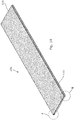
- an acoustic building damping material 100 comprising a substrate 110 and an acoustic damping layer 118 secured to the substrate 110.
- the substrate 110 is a load bearing structural substrate in the form of a flooring sheet which is approximately 499 mm in width and 2400mm in length.
- Flooring sheet 100 can support minimum static loads of 5KPa.
- the substrate 100 comprises a cementitious bound material, for example a fibre cement material with a density within the range of 900 to 1800 ⁇ 100 Kg/m 3 .
- Substrate 110 comprises a first face 112, a second face 114 and an intermediate portion 116 positioned between the first and second faces and an edge member 116a, 116b surrounding the intermediate portion.
- first and second faces, intermediate portion and edge member together integrally form a panel or sheet of predetermined thickness.
- the edge member or portion 116 of substrate layer 110 is provided with both a protruding or projecting member 116a and a receiving portion 116b, thereby comprising a tongue and groove configuration.
- the distance from the uppermost surface of the acoustic building damping material 100 to the opposing lowermost surface of the acoustic building damping material 100 is approximately 27mm, wherein the distance from the uppermost surface of the acoustic damping layer 118 to the opposing lowermost surface of the acoustic damping layer 118 is approximately 5.0mm and the distance from the uppermost surface of the substrate layer 110 to the opposing lowermost surface of the substrate layer 110 is approximately 22.0mm.
- the edge member 116 of the substrate layer is further provided with a chamfered or bevelled edge 116c (shown clearly in Figure 1b ) at the first face 112 of the substrate layer 110.
- This provides a user with a slightly opened area for a sealant to be applied easily between two adjacent sheets of the acoustic damping building material 100 of the invention.
- the chamfered or bevelled edge 116c enables a better seal to form between the adjacent sheets.
- the acoustic damping layer 118 is secured by gluing to the first face of the substrate layer 110 such that the acoustic damping layer 118 covers predominantly all of the first face of the substrate layer 110. Acoustic damping layer 118 does not extend to cover all of the first face 112 of the substrate layer 110, this is to allow for compression of the acoustic damping layer when a load is placed on the acoustic building damping material 100 of the invention.
- the uncovered area between the edge of the acoustic damping layer 118 and the edge portion 116 is approximately 2.25mm across the width of the board as shown in Figures 1b and 1c and approximately 2.0mm across the length of the board as shown in Figures 1d and 1e .
- the acoustic damping layer 118 can be arranged such that the acoustic damping layer 118 is positioned between the substrate 100 and the source of the sound energy or alternatively such that the acoustic damping layer 118 is remote from the source of the sound energy, i.e. the substrate 100 is located between the acoustic damping layer 118 and the source of the sound energy.
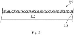
- Figure 2 shows a second embodiment of a portion of the acoustic damping building material 200 of the invention comprising a substrate 210 and an acoustic damping layer 218 secured thereto.
- Figure 3a shows a third embodiment of a portion of the acoustic damping building material 300 of the invention comprising a substrate 310 and a first and second acoustic damping layer 318 and 320 respectively.
- acoustic damping layers 218, 318 and 320 cover all of substrate 210, 310 respectively. It will be appreciated that it is possible for the damping layers to cover all or at least a portion of the substrate 210, 310 respectively.
- the acoustic damping layers 118, 218, 318 and 320 comprise two media wherein the media are configured such that each of the acoustic damping layers 118, 218, 318, 320 comprise at least one direct energy transmission pathway and at least one indirect energy transmission pathway through the acoustic damping layer 118, 218, 318, 320 to the substrate 210 and 310 respectively.
- the acoustic damping layer 118, 218, 318 320 are not drawn to scale, it is to be understood that in one embodiment of the invention, the acoustic damping layer 118, 218, 318, 320 has a depth of between approximately 1mm and 20mm from an exterior surface to an interior surface whereby the exterior surface is defined as the surface of the acoustic damping layer remote from the substrate 210 and 310 and the interior surface of the acoustic damping layer is adjacent the substrate 210 and 310 in any given configuration. In alternative embodiments of the invention the depth of the acoustic damping layer 118, 218, 318, 320 is any distance between approximately 2mm and 10mm.
- acoustic damping layers 318 and 320 are substantially the same.
- Each of the respective media 322 and 324 used in the acoustic damping layer 318 have a different transmission coefficient ( ⁇ ) to the other and are interspersed in the acoustic damping layer 318 to form the direct and indirect energy transmission pathways.
- the media of the acoustic damping layers can be any suitable media or material known to a person skilled in the art.
- the acoustic damping layer 318 comprises a polymeric material 322 which is in the form of a plurality of particles which have been dispersed and held in place by a polymeric binder 326.
- the polymer particles 322 are of irregular shape, consequently interstitial void volumes 324 are present between adjacent polymer particles 322.
- the polymer particles 322 are dispersed amongst each other within the acoustic damping layer 318 such that in some instances, a portion of the surface area 322a of the particles 322 are contiguous to a portion of the surface area of an adjacent particle 322 of the same media. This forms a direct energy transmission pathway through the polymer media of the acoustic damping layer.
- a portion of the surface area 322b of the polymer particles 322 are adjacent to a void volume 324 so as to form an indirect energy transmission pathway through the acoustic damping layer.
- the polymeric material 322 is selected from the group comprising natural rubbers, nitrile rubbers, butyl rubbers, silicone rubbers, EPDM, synthetic rubbers, polyacrylates, polyurethanes, vinyl polymers, copolymers.
- the polymeric binder 326 is selected from the group comprising emulsion polymers, polymer solutions, polymer dispersions, thermosetting polymers, and thermoplastic polymers.
- the void volume 324 is normally occupied by a mixture of gases, for example air. In all of the above any other materials known to a person skilled in the art which would achieve the object of the invention can also be used.
- the void volume 324 is in effect dispersed throughout the acoustic damping layer 318 due to the arrangement of the irregularly shaped particulate polymenc material 322.
- the void volume 324 occupies between 5 and 80% by volume of the acoustic damping layer. In further embodiments of the invention the void volume occupies between 10 and 50% by volume and between 15 and 35 % by volume of the acoustic damping layer respectively.
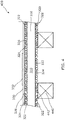
- acoustic damping building material 300 of Figure 3a comprising two acoustic damping layers 318 and 320 in use as a flooring material 400.
- the building material is secured to support 440 such that the acoustic damping layer 320 abuts the support 440 along the support surface 442.
- acoustic damping layer 320 adjacent support 440 has a greater depth than the acoustic damping layer 318 on the opposite side of the substrate 310.
- acoustic damping layer 318 has a depth that is approximately 2mm whilst acoustic damping layer 320 has a depth that is approximately 5mm.
- the advantage of this embodiment of the invention is that the acoustic damping layer 318 on the trafficable side of the flooring material is designed to reduce impact noise, whilst the acoustic damping layer 320 is designed to absorb, dissipate and limit the transfer of impact and vibration to the support 440 and consequently throughout the building structure.
- FIG. 5(a) to 5(f) there is shown an example of the steps of the method for installation flooring sheet 400 in a building structure.
- the acoustic damping building material 300 of Figure 3a is shown without defining the acoustic damping layers in Figures 5(a) to 5(e) .
- Figure 5(a) is an example a building subframe structure 440.
- the installer is shown reinforcing the building subframe structure 440 and securing a first and second section 300a and 300b respectively of the acoustic damping building material 300 of the invention to the building subframe structure 440 at predefined positions 440a on the subframe 440.
- Figure 5(f) shows an aesthetic surface layer 332 secured to the acoustic damping building material 300 for providing an aesthetic building finish.
- the acoustic damping building material is securable to the building subframe 440 by either mechanical or chemical means, wherein the mechanical means is selected from one or more of the group comprising nails, screws, scrails, staples, bolts, and masonry anchors; and the chemical means is by means of an appropriate adhesive.
- the acoustic damping building material 100, 200 or 300 of the invention were tested to determine airborne and impact transmissions.
- the acoustic damping building material 100, 200 or 300 was tested having either a single acoustic damping layer attached to one side of the substrate or a double acoustic damping layer wherein a single acoustic damping layer was secured to opposing sides of a substrate.
- the acoustic damping building material was secured to a building sub frame.
- the acoustic building material was also tested with and without an outer decorative surface, wherein the decorative surface was either a timber laminate or a ceramic tile as set out below. The temperature of the testing area was also recorded.
- Sound pressure levels are typically reported in decibel (dB) units. With 0dB representing the threshold of audibility for a person of normal hearing capacity and 100dB representing, say, the noise level in a subway railway station or heavy industrial machinery in operation. In a normal daily urban environment, a person may be exposed to sound levels such as average street noise at around 70dB, an average office environment at around 60dB, an average conversation at around 50dB, and a quiet or private office at around 40dB. The correlation between sound intensity and sound pressure is logarithmic and an increase of 10dB in sound pressure level represents a 10-fold increase in sound intensity level, so the sound intensity at 100dB is 10,000,000,000 times greater than that at 0dB.
- dB decibel
- a change of 1-2dB is not detectable.
- a change of 5dB is clearly detectable and a change of 10dB is regarded as either a halving (if reduced by 10dB) or doubling (if increased by 10dB) of the noise level.
- a relatively small change in dB sound levels may, in fact, represent a significant change in the sound intensity in an environment.
- Each material will have a characteristic sound absorption/transmission effectiveness depending not only its inherent material properties, but also its physical configuration such as shape, thickness and the like. Sound may also be transferred either directly through the material of a building section such as a wall or floor section &/or indirectly through airborne transmission.
- the ideal is to create an environment where sound intensity, through both direct and indirect transmission pathways, is below nuisance levels both for the person themselves and for any immediately adjacent neighbours.
- the first embodiment 100 of the acoustic damping building material of the invention was tested in a combined structural floor, ceiling configuration, such a configuration is typically found between storeys of a multi-storey building construction.
- the airborne noise transmission for the various embodiments of the invention is 60 and 62 Db (R w + C tr ) respectively, whilst the impact noise transmission for the various embodiments of the invention is between 55 and 64 Db (L n,Tw ).
- the results of the test exemplify that the various embodiments of the invention operated to reduce both airborne and impact acoustic, noise or sound transmissions to an acceptable level.
- the second and third embodiments (assembly) 200 and 300 respectively of the acoustic damping building material of the invention were tested at various temperatures as a flooring material to determine the effectiveness of the building material.
- the airborne noise transmission for the various embodiments of the invention is 60 and 63 Db (R w + C tr ) respectively, whilst the impact noise transmission for the various embodiments of the invention is between 52 and 59 Db (L n,Tw ).
- the results of the test exemplify that the various embodiments of the invention operated to reduce both airborne and impact acoustic, noise or sound transmissions to an acceptable level.
- the acoustic performance of all examples provided above meet or exceed the UK Building Code ADE AAA3 (Resistance to the Passage of Sound) provisions for an L' nT,w maximum value of 64 dB for floors, and stairs in buildings. (The lower the value the better).
- the L' nT,w value is the impact sound pressure level in a stated frequency band, corrected for reverberation time, according to BS EN ISO 140-7:1998.
- the R w (C tr ) standards for airborne noise transmission between rooms are also met or exceeded by all examples provided above.
- the R w (C tr ) is a measure of the is the weighted sound reduction index together with the traffic A-weighted spectrum added to take account of low frequency traffic noise in airborne transmissions.
Description
- The present invention relates to a building material and in particular a building material that is suitable for damping acoustic resonance or sound transmissions.
- It is recognised that acoustic resonance or sound transmissions within and between buildings is of great concern for building inhabitants, particularly as the density of habitation increases and as aesthetic tastes for hard surface finishes proliferates.
- One approach to reducing noise transmission through walls and floors of buildings is to use denser materials, which inherently limits sound transmission by acting as a barrier material which reflects sound waves or energy. However, use of denser materials does not address impact acoustic, noise or sound transmissions, whereby the noise or sound waves are formed in the denser material on impact.
- A further approach to reducing noise transmissions is found in multiple storey or multiple layer construction. In such systems, combined floor-ceiling installations are placed between storeys or floors. The combined floor-ceiling installations comprise multiple layers including for example, a central structural flooring sheet, to which varying combinations of drywall, gypsum board or plasterboard, insulation batts, insulation boards, insulation mats, concrete slabs, aesthetic floor surfaces which are arranged in various combinations to provide a reduction in transmitted sound intensity between the storeys or layers. The problem associated with such systems is the amount of space such installations occupy in the building structure. Ultimately, the height of the building and or the number of storeys often needs to be adjusted to allow for such installations.
- A further example of a noise reducing technique incorporates the use of roll out insulating mats, which are placed between a pre-existing building substrate and an aesthetic surface layer. Often such insulating mats are installed over existing concrete or timber structural floors. These mats may be compressed at the point(s) where a building sheet is fixed to a subframe through the mat. It is necessary to install a building sheet, for example, an MDF layer and/or battens over the acoustic mat(s) in order to fix a decorative hard surface to the floor. It is understood, that use of such measures does not effectively reduce transmission of sound energy within the construction.
-
CN 202 175 920 discloses a sound absorbing plate suitable for lining sides of municipal transportation fields according to the preamble of claim 1 and a corresponding production method according to the preamble of claim 8. - It is an object of the present invention to overcome or ameliorate at least one disadvantage of the prior art or to provide a useful alternative.
- According to the invention, there is provided an acoustic damping building material as set out in appended Claims 1 to 6. There is also provided an acoustic damping building system comprising a building subframe structure and as least one section of an acoustic damping building material of Claims 1 to 6 as set out in appended Claim 7. There is further provided a method for constructing an acoustic building system as set out in appended Claim 8.
- The advantage of the acoustic building material of the invention is that a single product provides multiple combinations of structure borne energy transmission pathways through which sound energy can be absorbed and/or transmitted. The acoustic building material of the invention comprises at least two differing media or materials comprising different properties which in turn generate multiple combinations of structure borne energy transmission pathways through which sound energy can be absorbed and/or transmitted. In use, the acoustic damping layer provides methods by which sound fluctuations can be absorbed and/or dissipated whilst the substrate layer provides a barrier material which reflects sound fluctuations back into the acoustic damping layer. The reflected sound fluctuations are then also absorbed and dissipated. In this way, acoustic noise can be limited via impact and acoustic or vibrational transfer of sound energy through the building structure.
- It is to be understood that throughout the specification, the term direct energy transmission pathway is used to describe a transmission pathway through the acoustic damping layer that enables energy to proceed through the media following a relatively straight course i.e. a pathway that is without interruption. In contrast the term indirect energy transmission pathway is used to describe a transmission pathway through the acoustic damping layer that does not follow such a course, i.e. may include one or more interruptions.
- The at least two media are interspersed amongst each other to form the direct and indirect energy transmission pathways.
- In one embodiment of the invention the acoustic damping layer comprises at least two media wherein one of the at least two media comprises a different transmission coefficient (τ) to the other of the at least two media.
- One of the at least two media comprises at least one polymeric material.
- In accordance with the invention one of the at least two media comprises one or more polymeric materials. Conveniently, the one or more polymeric materials each comprise a transmission coefficient (τ). Optionally, in one embodiment of the invention, the transmission coefficients (τ) of the one or more polymeric materials are the same for each of the polymeric materials. In an alternative embodiment of the invention, the transmission coefficients (τ) of the one or more polymeric materials are different for each of the one or more polymeric materials. In a further embodiment of the invention, wherein one of the at least two media comprises a combination of at least three polymeric materials, the transmission coefficients (τ) of the polymeric materials are optionally the same or different relative to each other.
- In accordance with the invention, the at least one polymeric material comprises a polymeric particulate material. In a further embodiment of the invention, the at least one polymeric particulate material comprises a plurality of particles dispersed within the acoustic damping layer. In a further embodiment of the invention the polymeric material is a granular material whereby the granular material comprises small and independent granules. Optionally the particles and/or granules have different shapes, for example, either regular or irregular shapes. In accordance with the invention the particles or granules are formed by crumbing or shredding a piece of the polymeric material. Conveniently in accordance with the invention, the polymeric particles or granules comprise a mixture of crumbed or shredded particles or granules.
- In accordance with the invention, the polymeric material is selected from the one or more of the group comprising natural rubbers, nitrile rubbers, butyl rubbers, silicone rubbers, Ethylene Propylene Diene Monomer rubber (EPDM), synthetic rubbers, polyacrylates, polyurethanes, vinyl polymers, copolymers.
- In accordance with the invention, the particles or granules of one of the at least two media and the other of the two media are dispersed amongst each other within the acoustic damping layer such that a portion of the particles or granules of one of the at least two media are contiguous to an adjacent particle or granule of the same media so as to form a direct energy transmission pathway through the acoustic damping layer and a portion of the particles or granules of the polymeric material of one of the at least two media are contiguous to an adjacent particle of the other of the at least two media so as to form an indirect energy transmission pathway through the acoustic damping layer. Optionally, wherein one of the at least two media comprises further polymeric materials, a portion of the particles or granules of the polymeric material of one of the at least two media are contiguous to either an adjacent particle of a particle or granule of a further polymeric material or the other of the at least two media so as to form an indirect energy transmission pathway through the acoustic damping layer.
- In accordance with the invention, the other of the at least two media comprises a void volume, wherein the void volume is understood to be a volume of unoccupied area or space dispersed within the acoustic damping layer.
- Conveniently, the one or more polymeric materials and the void volume are interspersed amongst each other, whereby the particles of one of the at least two media and the void volume or the other of the at least two media are dispersed amongst each other within the acoustic damping layer such that a portion of the particles of one of the at least two media are contiguous to an adjacent particle of the same media so as to form a direct energy transmission pathway through one of the at least two media of the acoustic damping layer and a portion of the particles of one of the at least two media are contiguous to an adjacent void volume so as to form an indirect energy transmission pathway through one of the at least two media of the acoustic damping layer.
- In one embodiment of the invention, the acoustic damping layer is provided as a continuous material wherein the at least two media are interwoven together to form the continuous material. Conveniently in one embodiment of the invention, the acoustic damping layer comprises a continuous material in the form of a mat which is used to cover the portion or all of the substrate material.
- Optionally, in one embodiment of the invention, the acoustic damping layer comprising polymeric particulate material is configured to have an outwardly appearing continuous line. In this way, the indirect and direct energy transmission pathways within the acoustic damping layer are not readily visible to the end user.
- In a further embodiment of the invention, the polymeric particulate material is arranged such that the acoustic damping laver comprising polymeric particulate material is in the form of a mat which is used to cover a portion of the substrate material.
- In accordance with the invention, the acoustic damping layer further comprises a polymeric binder. In one embodiment the polymeric binder is selected from the group comprising emulsion polymers, polymer solutions, polymer dispersions, thermosetting polymers, and thermoplastic polymers. In a further embodiment of the invention the polymeric binder comprises a mixture of a polymeric resin, water and one or more additives wherein the one or more additives are selected from the group comprising flow control agents, rheology modifiers, fire retardants, preservatives, fungicides, insecticides, pigments, colorants, water repelling agents and any other suitable additive known to a person skilled in the art. The polymeric binder can have a different or the same transmission coefficient (τ) as compared to one or both of the at least two media. Conveniently the polymeric binder is combined with one or more of the at least two media to bind the one or more of the at least two media together such that the at least two media are interspersed amongst each and the polymeric binder forms a non-continuous phase intermediate the interspersed at least two media thereby forming the direct and indirect energy transmission pathways.
- In a further embodiment of the invention, wherein one of the at least two media comprises at least two polymeric materials, optionally the at least two polymeric materials each comprise a polymeric particulate material. In one embodiment of the invention, the at least two polymeric particle materials and the void volume are dispersed amongst each other within the acoustic damping layer such that a portion of the particles of one of the at least two polymeric particle materials are contiguous to an adjacent particle of the same polymeric particle material so as to form a direct energy transmission pathway through one of the at least two polymeric particle material of the acoustic damping layer and a portion of the particles of one of the at least two polymeric particle materials are contiguous to an adjacent particle of the other of the at least two polymeric particle materials or a void volume so as to form an indirect energy transmission pathway through one of the at least two media of the acoustic damping layer.
- In accordance with the invention the acoustic damping layer comprises a mixture of crumbed and shredded polymeric material, a void volume and a polymeric binder wherein the crumbed and shredded polymeric material comprise approximately 60% ± 2% by weight of the acoustic damping layer and the polymeric binder comprises approximately 40% ± 2% by weight of the acoustic damping layer. In this embodiment of the invention, the ratio of crumbed polymeric material to shredded polymeric material is 1:1. Conveniently, the porosity of the acoustic damping layer of the invention is strictly controlled to ensure that the acoustic damping properties of the acoustic damping layer of the invention are enhanced.
- In accordance with the invention, the substrate comprises a first face, a second face and an intermediate portion positioned between the first and second faces and an edge portion surrounding the intermediate portion such that the first and second faces, intermediate portion and edge member together form a panel or sheet of predetermined thickness. In this embodiment of the invention, the first and second faces are opposing faces of the panel or sheet. In a further embodiment of the invention the intermediate portion and edge portion are integrally formed with the first and second faces of the substrate.
- In one embodiment of the invention, the substrate is a load bearing structural substrate, wherein the structural substrate is able to withstand static loading. It is be to understood that the static loading requirements are defined within each territory by the appropriate local or regulatory building codes. In one embodiment of the invention the load bearing structural substrate is a structural flooring sheet, panel or board. In one embodiment of the invention the load bearing structural substrate has a minimum loading level of 5KPa.
- In accordance with the invention the acoustic damping layer is secured to at least a portion of the first face of the substrate. Conveniently, the acoustic damping layer is secured by any appropriate means such that the acoustic damping layer is firmly attached to the substrate. When this embodiment of the invention is in use in a building structure, the acoustic damping building material can be arranged such that the acoustic damping layer is positioned between the substrate and the source of the sound energy or alternatively such that the acoustic damping layer is remote from the source of the sound energy, i.e. the substrate is located between the acoustic damping layer and the source of the sound energy. Advantageously, when the acoustic damping layer is positioned between the substrate and the source of sound energy, the direct and indirect energy transmission pathways of the acoustic damping layer operate to absorb and/or dissipate a significant amount of sound energy before the sound energy reaches the substrate layer.
- In a further embodiment of the invention the acoustic damping layer is secured to at least a portion of the first face and at least a portion of the second face of the substrate. Conveniently separate acoustic damping layers can be provided for the first and second face of the substrate respectively. The advantage of this embodiment of the invention is that any noise or sound energy which is transmitted through a first acoustic damping layer and the substrate is absorbed by the second acoustic damping layer on the opposite face.
- In one embodiment of the invention, the distance from one surface of the acoustic damping layer to an opposing surface is between approximately 1 mm and approximately 20mm thick. In a further embodiment of the invention, the distance between one surface of the acoustic damping layer to the opposing surface is between approximately 2mm and approximately 10mm. The advantage of this is that the acoustic damping layer is a thin layer which when combined with the substrate layer of the invention achieves acoustic damping/noise reduction without occupying a large spatial area.
- According to one embodiment of the invention, the substrate comprises a density within the range of 900 to 1800 ± 100 Kg/m3. The advantage of using a denser material is that is reduces airborne acoustic, noise or sound transmissions.
- According to one embodiment of the invention, the substrate comprises a cementitious bound material. In a further embodiment of the invention, the cementitious bound material comprises a fibre cement panel or sheet, for example, a fibre cement flooring sheet or a fibre cement building panel.
- The advantage of using a cementitious bound material as a substrate is that it provides a durable and workable material which has greater density than most wooden substrates normally used in construction. The cementitious bound material substrate together with acoustic damping layer of the invention provide an acoustic damping building material that reduces both airborne and impact acoustic, noise or sound transmissions.
- In a further embodiment of the invention, the distance between the first and second face of the substrate panel or sheet is between approximately 15mm and approximately 50mm. Optionally in one embodiment of the invention, the distance between one surface of the acoustic damping building layer and the opposing surface wherein the acoustic damping building layer comprises the substrate panel and the acoustic layer is between approximately 19mm and 27mm. Thus in one embodiment of the invention, the distance between one surface of the acoustic damping building material and an opposing surface can achieve distances of 16mm to 70mm as compared to an equivalent distance of more than 200mm in prior art systems.
- In a further embodiment of the invention the edge portion of the substrate further comprises a protruding or projecting member which extends beyond the edge of the first and/or second face of the substrate. In a further embodiment of the invention the edge portion further comprises a receiving portion which is sized and shaped such that it is adapted to receive a complimentary shaped protruding or projecting member extending beyond the edge of the first and/or second face of the substrate. Conveniently, in a further embodiment of the invention the edge portion of a substrate layer is provided with both a protruding or projecting member and a receiving portion. In such an arrangement the protruding or projecting member and receiving portion are arranged on the edge portion such that the protruding or projecting member of a first substrate layer can seat within a receiving portion of an adjacent substrate layer when two or more substrate layers are nested together. In a further embodiment of the invention, the protruding or projecting member of the substrate and/or the receiving portion are configured to facilitate provision of a cavity intermediate the protruding or projecting member and the receiving portion, such that a securing material, for example, a sealant or adhesive can be placed in the cavity. The securing material acts to secure two or more substrate layers together in a nested arrangement. Advantageously, the securing material can also act as an acoustic damping material.
- In a further embodiment of the invention, the acoustic damping building material comprises an outer layer, wherein the outer layer is provided on the outermost surface of the acoustic damping building material which is normally visible to the end user. Conveniently, the outer layer provides a smoother and more durable surface for the end user, for example, an aesthetic coating such as a skimmed coating of a cementitious material or a flooring surface. It is to be understood that any suitable outer layer known to a person skilled in the art which will achieve the function of the outer layer can also be used. Conveniently, it is possible to fix the outer layer, for example, a tile finishing layer, directly to the acoustic damping layer. In a further embodiment of the invention, the outer layer comprises an optimising layer and a finishing layer, wherein the optimising layer is used to improve surface flatness and/or provide additional structural support for the finishing layer. An example of such an embodiment of the invention is the use of a screed as the optimising layer to improve surface flatness and provide additional structural support for a tile finishing layer. It is to be understood that the acoustic properties of the acoustic damping building material are maintained when using an outer layer. Conveniently, in a further embodiment of the invention, the acoustic damping building material is suitable for use as a structural floor surface for an underfloor heating system wherein the pipes for the underfloor heating are provided between the joists of the flooring structure.
- According to the invention, there is further provided an acoustic damping building system comprising:
- a building subframe structure,
- at least one section of acoustic damping building material according to the invention as set out in appended Claims 1 to 6.
- The advantage of the acoustic damping building system of the invention is that the acoustic energy generated directly or indirectly within the aesthetic surface layer is damped by the or each acoustic damping building material section, which leads to abatement of acoustic noise transmission to adjacent room spaces through the building subframe structure.
- In one embodiment of the invention, the acoustic damping building material is securable to the building subframe by mechanical means, wherein the mechanical means is selected from one or more of the group comprising nails, screws, scrails, staples, bolts, and masonry anchors. Optionally, in one embodiment of the invention, the acoustic damping building material is securable to the building subframe by a concealed fixing system. In a further embodiment of the invention, the acoustic damping building material is securable to the building subframe by chemical means, for example, by means of an adhesive. In a further embodiment of the invention, the acoustic damping material is securable to the building subframe using a combination of mechanical and chemical means.
- According to the invention, there is provided a method of constructing an acoustic damping building system comprising the steps of:
- (a) providing a building subframe structure;
- (b) providing at least one section of acoustic damping building material as set out in appended Claims 1 to 6;
- (c) Installing a section of the acoustic damping building material by positioning the acoustic damping building material into a user selectable position on the building subframe and securing it to the building subframe; and
- (d) applying and securing a surface layer to the acoustic damping layer on the acoustic damping building material to provide an aesthetic finish.
- In one embodiment of the invention, the method of constructing an acoustic damping building system further comprises after step (c) the further steps of:
- (c1) Securing a subsequent section of the acoustic damping building material onto the building subframe relative to the previously installed section of acoustic damping building material, and securing it to the building subframe,
- (c2)Repeating step (c1) until the desired building section is covered.
- In one embodiment of the invention, the acoustic damping building material is securable to the building subframe by mechanical means, wherein the mechanical means is selected from one or more of the group comprising nails, screws, scrails, staples, bolts, and masonry anchors. Optionally, in one embodiment of the invention, the acoustic damping building material is securable to the building subframe by a concealed fixing system. In a further embodiment of the invention, the acoustic damping building material is securable to the building subframe by chemical means, for example, by means of an adhesive. In a further embodiment of the invention, the acoustic damping material is securable to the building subframe using a combination of mechanical and chemical means.
- In a further embodiment of the invention, the acoustic damping building material is suitable for use in combination with other acoustic damping building materials. In particular the acoustic damping building material of the invention is suitable for use with an acoustic dampener comprising: a base member, wherein the base member comprises a first surface and a second surface, the first and second surface being spaced apart from each other defining a thickness there between; at least two side arms, wherein each side arm comprises a first end and a second end, each side arm extending from the first surface of the base member at a pre-determined angle, such that there is a channel formed whereby each side arm and the base member form the sides and the base of the channel formation respectively; and a pair of flanges, each flange extending substantially orthogonally from the second end of each side arm and wherein the predetermined angle is elastically deformable. In this embodiment of the invention the channel formation is configured to receive a batten and the or each flange is configured to retain a batten within the channel.
- According to a further embodiment of the invention there is also provided a floor structure comprising acoustic damping building material and an acoustic dampener securable to a structural substrate, a batten disposed within the channel formation and flooring material secured to the batten.
- Other advantages of the invention are that the acoustic damping building material provides a lightweight alternative to other acoustic damping systems, which do not require application of multiple layers or skills from different trades. Use of a single layer of material, and the associated reduction in spacing between floors or walls means a reduction in building and materials costs which is hugely advantageous for the end user.
- The invention will now be described more particularly with reference to the accompanying drawings, which show by way of example only three embodiments of the acoustic damping building material of the invention.
- In the drawings,
-
Figure 1A is a perspective view of an acoustic flooring system according to the invention; -
Figure 1b is an enlarged partial end view of a first corner A of the acoustic flooring system ofFigure 1A ; -
Figure 1c is an enlarged partial end view of a second corner B of the acoustic flooring system ofFigure 1A ; -
Figure 1d is an enlarged partial side view of one side of the acoustic flooring system ofFigure 1A ; -
Figure 1e is an enlarged partial side view of a second side of the acoustic flooring system ofFigure 1A ; -
Figure 2 is a cross-sectional side view of a portion of an acoustic damping building material according to a second embodiment of the present invention; -
Figure 3a is a cross-sectional side view of a portion of an acoustic building damping material according to a third embodiment of the present invention; -
Figure 3b is an enlarged cross-sectional side view of section A of the acoustic building damping material ofFigure 3a ; -
Figure 3c is a further enlarged cross-sectional side view of section B of the acoustic building damping material ofFigure 3a ; -
Figure 4 is a cross-sectional side view of a portion of an acoustic flooring sheet according to one embodiment of the present invention, and -
Figures 5(a) to 5(f) are a series of perspective views of the steps of installing an acoustic damping building system according to one embodiment of the present invention. - Referring now to the drawings and specifically to
Figure 1A to 1e , there is shown a first embodiment of an acousticbuilding damping material 100 comprising asubstrate 110 and an acoustic dampinglayer 118 secured to thesubstrate 110. In the embodiment shown thesubstrate 110 is a load bearing structural substrate in the form of a flooring sheet which is approximately 499 mm in width and 2400mm in length.Flooring sheet 100 can support minimum static loads of 5KPa. In this embodiment of the invention, thesubstrate 100 comprises a cementitious bound material, for example a fibre cement material with a density within the range of 900 to 1800 ± 100 Kg/m3. -
Substrate 110 comprises afirst face 112, asecond face 114 and anintermediate portion 116 positioned between the first and second faces and anedge member portion 116 ofsubstrate layer 110 is provided with both a protruding or projectingmember 116a and a receivingportion 116b, thereby comprising a tongue and groove configuration. In this embodiment of the invention the distance from the uppermost surface of the acousticbuilding damping material 100 to the opposing lowermost surface of the acousticbuilding damping material 100 is approximately 27mm, wherein the distance from the uppermost surface of the acoustic dampinglayer 118 to the opposing lowermost surface of the acoustic dampinglayer 118 is approximately 5.0mm and the distance from the uppermost surface of thesubstrate layer 110 to the opposing lowermost surface of thesubstrate layer 110 is approximately 22.0mm. Theedge member 116 of the substrate layer is further provided with a chamfered orbevelled edge 116c (shown clearly inFigure 1b ) at thefirst face 112 of thesubstrate layer 110. This provides a user with a slightly opened area for a sealant to be applied easily between two adjacent sheets of the acoustic dampingbuilding material 100 of the invention. The chamfered orbevelled edge 116c enables a better seal to form between the adjacent sheets. - In the embodiment of the invention shown in
Figures 1A to 1e , the acoustic dampinglayer 118 is secured by gluing to the first face of thesubstrate layer 110 such that the acoustic dampinglayer 118 covers predominantly all of the first face of thesubstrate layer 110. Acoustic dampinglayer 118 does not extend to cover all of thefirst face 112 of thesubstrate layer 110, this is to allow for compression of the acoustic damping layer when a load is placed on the acousticbuilding damping material 100 of the invention. In the embodiment shown the uncovered area between the edge of the acoustic dampinglayer 118 and theedge portion 116 is approximately 2.25mm across the width of the board as shown inFigures 1b and 1c and approximately 2.0mm across the length of the board as shown inFigures 1d and 1e . - Conveniently when this embodiment of the invention is in use in a building structure, the acoustic damping
layer 118 can be arranged such that the acoustic dampinglayer 118 is positioned between thesubstrate 100 and the source of the sound energy or alternatively such that the acoustic dampinglayer 118 is remote from the source of the sound energy, i.e. thesubstrate 100 is located between the acoustic dampinglayer 118 and the source of the sound energy. - Referring now to
Figure 2 andFigures 3a to 3c .Figure 2 shows a second embodiment of a portion of the acoustic dampingbuilding material 200 of the invention comprising asubstrate 210 and an acoustic dampinglayer 218 secured thereto.Figure 3a shows a third embodiment of a portion of the acoustic dampingbuilding material 300 of the invention comprising asubstrate 310 and a first and second acoustic dampinglayer layers substrate substrate - In the embodiments shown, the acoustic damping
layers layers layer substrate layer layer substrate substrate layer - Referring specifically to
Figures 3b and 3c , there are shown enlarged cross sectional views of the media of the acoustic dampinglayers layers respective media layer 318 have a different transmission coefficient (τ) to the other and are interspersed in the acoustic dampinglayer 318 to form the direct and indirect energy transmission pathways. It is to be understood that the media of the acoustic damping layers can be any suitable media or material known to a person skilled in the art. In the embodiment shown, the acoustic dampinglayer 318 comprises apolymeric material 322 which is in the form of a plurality of particles which have been dispersed and held in place by apolymeric binder 326. - The
polymer particles 322 are of irregular shape, consequentlyinterstitial void volumes 324 are present betweenadjacent polymer particles 322. Thepolymer particles 322 are dispersed amongst each other within the acoustic dampinglayer 318 such that in some instances, a portion of thesurface area 322a of theparticles 322 are contiguous to a portion of the surface area of anadjacent particle 322 of the same media. This forms a direct energy transmission pathway through the polymer media of the acoustic damping layer. Similarly, in some instances a portion of thesurface area 322b of thepolymer particles 322 are adjacent to avoid volume 324 so as to form an indirect energy transmission pathway through the acoustic damping layer. - In the embodiments of the invention shown, the
polymeric material 322 is selected from the group comprising natural rubbers, nitrile rubbers, butyl rubbers, silicone rubbers, EPDM, synthetic rubbers, polyacrylates, polyurethanes, vinyl polymers, copolymers. Thepolymeric binder 326 is selected from the group comprising emulsion polymers, polymer solutions, polymer dispersions, thermosetting polymers, and thermoplastic polymers. Thevoid volume 324 is normally occupied by a mixture of gases, for example air. In all of the above any other materials known to a person skilled in the art which would achieve the object of the invention can also be used. - The
void volume 324 is in effect dispersed throughout the acoustic dampinglayer 318 due to the arrangement of the irregularly shapedparticulate polymenc material 322. Although not specifically shown in the drawings, in one embodiment of the invention, thevoid volume 324 occupies between 5 and 80% by volume of the acoustic damping layer. In further embodiments of the invention the void volume occupies between 10 and 50% by volume and between 15 and 35 % by volume of the acoustic damping layer respectively. - Referring to
Figure 4 , there is shown the acoustic dampingbuilding material 300 ofFigure 3a comprising two acoustic dampinglayers flooring material 400. The building material is secured to support 440 such that the acoustic dampinglayer 320 abuts thesupport 440 along thesupport surface 442. Although not shown, it is to be understood that optionally in this embodiment of the invention, acoustic dampinglayer 320adjacent support 440 has a greater depth than the acoustic dampinglayer 318 on the opposite side of thesubstrate 310. In one embodiment of the invention, acoustic dampinglayer 318 has a depth that is approximately 2mm whilst acoustic dampinglayer 320 has a depth that is approximately 5mm. The advantage of this embodiment of the invention is that the acoustic dampinglayer 318 on the trafficable side of the flooring material is designed to reduce impact noise, whilst the acoustic dampinglayer 320 is designed to absorb, dissipate and limit the transfer of impact and vibration to thesupport 440 and consequently throughout the building structure. - Referring now also to 5(a) to 5(f), there is shown an example of the steps of the method for
installation flooring sheet 400 in a building structure. For the purposes of clarity, the acoustic dampingbuilding material 300 ofFigure 3a is shown without defining the acoustic damping layers inFigures 5(a) to 5(e) .Figure 5(a) is an example abuilding subframe structure 440. InFigures 5(b) to 5(d) the installer is shown reinforcing thebuilding subframe structure 440 and securing a first andsecond section building material 300 of the invention to thebuilding subframe structure 440 atpredefined positions 440a on thesubframe 440.Figure 5(f) shows anaesthetic surface layer 332 secured to the acoustic dampingbuilding material 300 for providing an aesthetic building finish. It is to be understood that the acoustic damping building material is securable to thebuilding subframe 440 by either mechanical or chemical means, wherein the mechanical means is selected from one or more of the group comprising nails, screws, scrails, staples, bolts, and masonry anchors; and the chemical means is by means of an appropriate adhesive. - The acoustic damping
building material building material - Sound pressure levels are typically reported in decibel (dB) units. With 0dB representing the threshold of audibility for a person of normal hearing capacity and 100dB representing, say, the noise level in a subway railway station or heavy industrial machinery in operation. In a normal daily urban environment, a person may be exposed to sound levels such as average street noise at around 70dB, an average office environment at around 60dB, an average conversation at around 50dB, and a quiet or private office at around 40dB. The correlation between sound intensity and sound pressure is logarithmic and an increase of 10dB in sound pressure level represents a 10-fold increase in sound intensity level, so the sound intensity at 100dB is 10,000,000,000 times greater than that at 0dB. For a person of normal hearing, a change of 1-2dB is not detectable. A change of 5dB, however, is clearly detectable and a change of 10dB is regarded as either a halving (if reduced by 10dB) or doubling (if increased by 10dB) of the noise level. A relatively small change in dB sound levels may, in fact, represent a significant change in the sound intensity in an environment.
- Many sounds that people are exposed to in a modern environment span across a range of frequencies from about 50 Hz up to about 10kHz. Voices are predominantly in the 100-300 Hz range. Heavy vehicles may be in the 50-1000 Hz range and car horns are in the AAA-5000 Hz range. All of the sounds in an environment may reach a person at different sound intensity depending on how far away they are from the source, any material between the person and the source of the sound that may act to absorb or transmit those sounds, and the sound travel pathways available.
- Each material will have a characteristic sound absorption/transmission effectiveness depending not only its inherent material properties, but also its physical configuration such as shape, thickness and the like. Sound may also be transferred either directly through the material of a building section such as a wall or floor section &/or indirectly through airborne transmission.
- Creating an environment for people, such as in residential dwellings or office/commercial spaces, requires that noise or sound intensity levels are managed. The ideal is to create an environment where sound intensity, through both direct and indirect transmission pathways, is below nuisance levels both for the person themselves and for any immediately adjacent neighbours.
- In order for the acoustic damping building material of the invention to achieve adequate noise reduction, it is necessary for the airborne noise transmission to be greater than 45dB.
- The
first embodiment 100 of the acoustic damping building material of the invention was tested in a combined structural floor, ceiling configuration, such a configuration is typically found between storeys of a multi-storey building construction. As set out below in Table One, the airborne noise transmission for the various embodiments of the invention is 60 and 62 Db (Rw + Ctr) respectively, whilst the impact noise transmission for the various embodiments of the invention is between 55 and 64 Db (Ln,Tw). The results of the test exemplify that the various embodiments of the invention operated to reduce both airborne and impact acoustic, noise or sound transmissions to an acceptable level.TEST -TABLE ONE Assembly Detail Floor Covering Structural Floor Ceiling Configuration Airbourne/ dB Rw (Ctr) Impact/ dB LnT,w Temp /° C 100 Single Acoustic Damping Layer and Fibre Cement Substrate 27mm Joists with minimum spacing of 240mm Insulation: 100mm with min value of 10kg/m3; 62 (-9) 57 15 Resilient 100 Fibre Cement Substrate and Single Acoustic Damping Layer 27mm** Bars: 16mm x 0.45mm metal resilient bar; 60 (-10) 64 15 100 Single Acoustic Damping Layer and Fibre Cement Substrate 27mm 6mm Ceramic tile laid on flexible tile adhesive 1st and 2nd ceiling layers: 15mm Gypsum board 912.5Kg/m2 na 55 15 ** The single acoustic damping layer was on the lower side of the substrate layer adjacent the structural floor. - The second and third embodiments (assembly) 200 and 300 respectively of the acoustic damping building material of the invention were tested at various temperatures as a flooring material to determine the effectiveness of the building material. As set out below in Table Two, the airborne noise transmission for the various embodiments of the invention is 60 and 63 Db (Rw + Ctr) respectively, whilst the impact noise transmission for the various embodiments of the invention is between 52 and 59 Db (Ln,Tw). The results of the test exemplify that the various embodiments of the invention operated to reduce both airborne and impact acoustic, noise or sound transmissions to an acceptable level.
TEST - TABLE TWO Assembly Detail Floor Covering Airborne/dB Rw (Ctr) Impact/dB LnT,w Temp/° C 200 Single Acoustic damping layer None 60 (-8) 58 6 200 Single Acoustic damping layer Timber laminate 62 (-9) 55 6 200 Single Acoustic damping layer Ceramic Tile Not Tested 59 6 300 Double Acoustic damping layer None 61 (-10) 59 6-7 300 Double Acoustic damping layer Timber laminate 63 (-8) 52 6-7 300 Double Acoustic damping layer None (Room Heated) Not Tested 58 16-17 300 Double Acoustic damping layer Ceramic Tile Not Tested 57 11 Airborne pass - >45dB
Impact Pass - <62dB - The acoustic performance of all examples provided above meet or exceed the UK Building Code ADE AAA3 (Resistance to the Passage of Sound) provisions for an L'nT,w maximum value of 64 dB for floors, and stairs in buildings. (The lower the value the better). The L'nT,w value is the impact sound pressure level in a stated frequency band, corrected for reverberation time, according to BS EN ISO 140-7:1998.
- The Rw (Ctr) standards for airborne noise transmission between rooms are also met or exceeded by all examples provided above. The Rw (Ctr) is a measure of the is the weighted sound reduction index together with the traffic A-weighted spectrum added to take account of low frequency traffic noise in airborne transmissions.
Claims (8)
- An acoustic damping building material (100, 200, 300) comprising;a substrate having a first face, a second face and an intermediate portion positioned between the first and second faces and an edge portion surrounding the intermediate portion such that the first and second faces, intermediate portion and edge member together form a panel or sheet of predetermined thickness;an acoustic damping layer (118, 218, 318) comprising at least two media (322, 324) wherein one of the at least two media comprises at least one polymeric material (322) and the other of the at least two media is a void volume (324); and a polymeric binder (326), wherein the at least one polymeric material and void volume (324) are configured such that the acoustic damping layer comprises at least one direct energy transmission pathway and at least one indirect energy transmission pathway through the acoustic damping layer to the substratewhereby the crumbed and shredded polymeric material of the at least one polymeric material (322) are dispersed amongst each other within the acoustic damping layer such that a portion of the particles or granules of the crumbed and shredded polymeric material are contiguous to an adjacent particle or granule of the same media so as to form a direct energy transmission pathway through the acoustic damping layer and a portion of the particles or granules of the crumbed and shredded polymeric material are contiguous to a void volume so as to form an indirect energy transmission pathway through the acoustic damping layer such that sound energy can be absorbed or transmitted,characterised in thatthe acoustic damping layer is secured to at least a portion of the first face of the substrate (110, 210, 310) such that the acoustic damping layer does not extend to cover all of the first face of the fibre cement substrate,the at least one polymeric material of the acoustic damping layer comprising a polymeric particulate material or a polymeric granular material selected from the group comprising natural rubbers, nitrile rubbers, butyl rubbers, silicone rubbers, EPDM, synthetic rubbers, polyacrylates, polyurethanes, vinyl polymers, copolymers; wherein the at least one polymeric material is a mixture of crumbed and shredded polymeric material; and wherein the ratio of crumbed to shredded polymeric material is 1:1 and the crumbed and shredded polymeric material comprises 60% ± 2% by weight of the acoustic damping layer,the polymeric binder (326) of the acoustic damping layer further comprising 40% ± 2% by weight of the acoustic damping layer; and the substrate is a fibre cement substrate (110, 210, 310).
- An acoustic damping building material as claimed in Claim 1, wherein one of the at least two media comprises one or more further polymeric materials, a portion of the particles or granules of the polymeric material of one of the at least two media are contiguous to either an adjacent particle of a particle or granule of one or more further polymeric materials or the other of the at least two media so as to form an indirect energy transmission pathway through the acoustic damping layer.
- An acoustic damping building material as claimed in any one of the preceding claims, wherein the polymeric binder is selected from the group comprising emulsion polymers, polymer solutions, polymer dispersions, thermosetting polymers, and thermoplastic polymers.
- An acoustic damping building material as claimed in Claim 1, wherein the predetermined thickness of the substrate panel or sheet is between approximately 15mm and approximately 50mm.
- An acoustic damping building material as claimed Claim 1, wherein the acoustic damping layer is also secured to at least a portion of the second face of the substrate.
- An acoustic damping building material as claimed in any one of the preceding claims, wherein the substrate comprises a material having a density between 900 and 1800 kg/m3.
- An acoustic damping building system comprising:a building subframe structure (440),at least one section of an acoustic damping building material according to any one of the preceding claims, the or each section of acoustic damping building sheet being securable to the building subframe structure, andan aesthetic surface layer securable to the or each acoustic damping building sheet, for providing an aesthetic building finish.
- A method of constructing an acoustic damping building system comprising the steps of:(a) providing a building subframe structure (440);(b) providing at least one section of acoustic damping building material according to the invention, the acoustic damping building material comprising: a substrate having a first face, a second face and an intermediate portion positioned between the first and second faces and an edge portion surrounding the intermediate portion such that the first and second faces, intermediate portion and edge member together form a panel or sheet of predetermined thickness; an acoustic damping layer (118, 218, 318) comprising at least two media (322, 324) wherein one of the at least two media comprises at least one polymeric material (322) and the other of the at least two media is a void volume (324); and
a polymeric binder (326), wherein the at least one polymeric material and void volume (324) are configured such that the acoustic damping layer comprises at least one direct energy transmission pathway and at least one indirect energy transmission pathway through the acoustic damping layer to the substrate whereby the crumbed and shredded polymeric material of the at least one polymeric material (322) are dispersed amongst each other within the acoustic damping layer such that a portion of the particles or granules of the crumbed and shredded polymeric material are contiguous to an adjacent particle or granule of the same media so as to form a direct energy transmission pathway through the acoustic damping layer and a portion of the particles or granules of the crumbed and shredded polymeric material are contiguous to a void volume so as to form an indirect energy transmission pathway through the acoustic damping layer such that sound energy can be absorbed or transmitted, characterised in that
the acoustic damping layer is secured to at least a portion of the first face of the substrate (110, 210, 310) such that the acoustic damping layer does not extend to cover all of the first face of the fibre cement substrate,
the at least one polymeric material of the acoustic damping layer comprising a polymeric particulate material or a polymeric granular material selected from the group comprising natural rubbers, nitrile rubbers, butyl rubbers, silicone rubbers, EPDM, synthetic rubbers, polyacrylates, polyurethanes, vinyl polymers, copolymers; wherein the at least one polymeric material is a mixture of crumbed and shredded polymeric material; and wherein the ratio of crumbed to shredded polymeric material is 1:1 and the crumbed and shredded polymeric material comprises 60% ± 2% by weight of the acoustic damping layer,
the polymeric binder (326) of the acoustic damping layer further comprising 40% ± 2% by weight of the acoustic damping layer; and the substrate is a fibre cement substrate (110, 210, 310).(c) Installing a section of the acoustic damping building material by positioning the acoustic damping building material into a user selectable position on the building subframe and securing it to the building subframe;(d) applying and securing a surface layer to the acoustic damping layer on the acoustic damping building material to provide an aesthetic finish; and optionally after step (c) the further steps of:(c1) Securing a subsequent section of the acoustic damping building material onto the building subframe relative to the previously installed section of acoustic damping building material, and securing it to the building subframe,(c2) Repeat step (c1) until the desired building section is covered.
Applications Claiming Priority (3)
| Application Number | Priority Date | Filing Date | Title |
|---|---|---|---|
| GB1308520.4A GB2517125A (en) | 2013-05-13 | 2013-05-13 | An acoustic damping building material |
| GB1322669.1A GB2521603B (en) | 2013-12-20 | 2013-12-20 | An acoustic damping building material |
| PCT/EP2014/059791 WO2014184205A1 (en) | 2013-05-13 | 2014-05-13 | An acoustic damping building material |
Publications (2)
| Publication Number | Publication Date |
|---|---|
| EP3004480A1 EP3004480A1 (en) | 2016-04-13 |
| EP3004480B1 true EP3004480B1 (en) | 2021-06-23 |
Family
ID=50721791
Family Applications (1)
| Application Number | Title | Priority Date | Filing Date |
|---|---|---|---|
| EP14723798.6A Revoked EP3004480B1 (en) | 2013-05-13 | 2014-05-13 | An acoustic damping building material |
Country Status (7)
| Country | Link |
|---|---|
| US (1) | US9567742B2 (en) |
| EP (1) | EP3004480B1 (en) |
| KR (1) | KR20160006761A (en) |
| AU (1) | AU2014267406B2 (en) |
| CA (1) | CA2910412C (en) |
| NZ (1) | NZ713435A (en) |
| WO (1) | WO2014184205A1 (en) |
Families Citing this family (6)
| Publication number | Priority date | Publication date | Assignee | Title |
|---|---|---|---|---|
| EP3004480B1 (en) | 2013-05-13 | 2021-06-23 | James Hardie Technology Limited | An acoustic damping building material |
| CN105155798A (en) * | 2015-06-24 | 2015-12-16 | 倪传华 | Purifying denoising fireproof anticorrosion fluorescent wallpaper |
| US20180330709A1 (en) * | 2017-05-10 | 2018-11-15 | Battelle Memorial Institute | Sound Attenuation Using Metal-Organic Framework Materials |
| US11120783B2 (en) * | 2018-09-07 | 2021-09-14 | GM Global Technology Operations LLC | Composite article for mitigating noise, vibration, and harshness |
| US10975562B2 (en) | 2018-11-13 | 2021-04-13 | Katerra Inc. | Smart corner and wall frame system |
| CN110748042A (en) * | 2019-10-24 | 2020-02-04 | 中国十七冶集团有限公司 | Sound insulation type steel plate concrete shear wall for high-rise building |
Citations (10)
| Publication number | Priority date | Publication date | Assignee | Title |
|---|---|---|---|---|
| GB220679A (en) * | 1923-03-22 | 1924-08-22 | Gerald Otley Case | Improvements in or relating to methods of road and pavement construction and road block manufacture in which the surface is formed of rubber |
| DE3132742A1 (en) * | 1981-08-19 | 1983-03-03 | Albert Bruens GmbH, 4404 Telgte | Panel, in particular floor panel, and process for the production thereof |
| JPH03161652A (en) | 1989-11-20 | 1991-07-11 | Central Glass Co Ltd | Floor member with sound insulating cushion |
| JPH10238089A (en) | 1997-02-27 | 1998-09-08 | Central Glass Co Ltd | Soundproof floor backing material |
| US6194519B1 (en) | 1998-07-20 | 2001-02-27 | Christopher Blalock | Products useful as roof shingles and a process for making such products |
| US20030225171A1 (en) | 2002-05-31 | 2003-12-04 | Westinghouse Air Brake Technologies Corporation | Process for recycling rubber |
| US20060014917A1 (en) | 2002-05-16 | 2006-01-19 | Mcp Industries, Inc. | Moisture-curing polyurethane material having a long gel time |
| WO2006082114A2 (en) | 2005-02-04 | 2006-08-10 | Lafarge Platres | Process for manufacturing sound absorbing cement tile |
| GB2438072A (en) | 2006-05-09 | 2007-11-14 | Glenn Melvin | A dry composition for preparing a flowable mixture for acoustic sound insulation |
| CN202175920U (en) * | 2011-07-12 | 2012-03-28 | 中交物产集团有限公司 | Sound absorption plate |
Family Cites Families (13)
| Publication number | Priority date | Publication date | Assignee | Title |
|---|---|---|---|---|
| US3070474A (en) * | 1958-08-19 | 1962-12-25 | Owens Illinois Glass Co | Bonded glass surfaces and method therefor |
| US4702046A (en) * | 1985-11-08 | 1987-10-27 | General Communications, Inc. | Acoustical wall panel |
| US4989688A (en) * | 1989-02-16 | 1991-02-05 | Soltech, Inc. | Acoustical wall panel and method of assembly |
| ZA937092B (en) * | 1992-10-01 | 1994-04-22 | Plascon Tech | Building component |
| CA2179110C (en) | 1996-06-13 | 2004-08-10 | Jozef Cipin | Insulating construction material |
| MY125251A (en) * | 1999-10-08 | 2006-07-31 | James Hardie Int Finance B V | Fiber-cement/gypsum laminate composite building material |
| US20050194210A1 (en) * | 2004-03-08 | 2005-09-08 | The Boeing Company | Apparatus and method for aircraft cabin noise attenuation via non-obstructive particle damping |
| US20060037815A1 (en) * | 2004-08-18 | 2006-02-23 | Schabel Norman G Jr | Particulate insulation materials |
| US7566475B2 (en) * | 2004-11-09 | 2009-07-28 | International Automotive Components Group North America, Inc. | Acoustic insulator with controlled airflow resistance and method of making same |
| US20100282632A1 (en) * | 2007-06-12 | 2010-11-11 | Schabel Jr Norman G | Lightweight pelletized materials |
| FR2929746B1 (en) * | 2008-04-07 | 2010-09-03 | Hutchinson | ACOUSTIC INSULATION PANEL |
| US20140044955A1 (en) * | 2012-01-26 | 2014-02-13 | Schabel Polymer Technology, Llc | Lightweight polymer pellet |
| EP3004480B1 (en) | 2013-05-13 | 2021-06-23 | James Hardie Technology Limited | An acoustic damping building material |
-
2014
- 2014-05-13 EP EP14723798.6A patent/EP3004480B1/en not_active Revoked
- 2014-05-13 CA CA2910412A patent/CA2910412C/en active Active
- 2014-05-13 KR KR1020157034999A patent/KR20160006761A/en not_active Application Discontinuation
- 2014-05-13 WO PCT/EP2014/059791 patent/WO2014184205A1/en active Application Filing
- 2014-05-13 US US14/888,932 patent/US9567742B2/en active Active
- 2014-05-13 AU AU2014267406A patent/AU2014267406B2/en active Active
- 2014-05-13 NZ NZ713435A patent/NZ713435A/en unknown
Patent Citations (10)
| Publication number | Priority date | Publication date | Assignee | Title |
|---|---|---|---|---|
| GB220679A (en) * | 1923-03-22 | 1924-08-22 | Gerald Otley Case | Improvements in or relating to methods of road and pavement construction and road block manufacture in which the surface is formed of rubber |
| DE3132742A1 (en) * | 1981-08-19 | 1983-03-03 | Albert Bruens GmbH, 4404 Telgte | Panel, in particular floor panel, and process for the production thereof |
| JPH03161652A (en) | 1989-11-20 | 1991-07-11 | Central Glass Co Ltd | Floor member with sound insulating cushion |
| JPH10238089A (en) | 1997-02-27 | 1998-09-08 | Central Glass Co Ltd | Soundproof floor backing material |
| US6194519B1 (en) | 1998-07-20 | 2001-02-27 | Christopher Blalock | Products useful as roof shingles and a process for making such products |
| US20060014917A1 (en) | 2002-05-16 | 2006-01-19 | Mcp Industries, Inc. | Moisture-curing polyurethane material having a long gel time |
| US20030225171A1 (en) | 2002-05-31 | 2003-12-04 | Westinghouse Air Brake Technologies Corporation | Process for recycling rubber |
| WO2006082114A2 (en) | 2005-02-04 | 2006-08-10 | Lafarge Platres | Process for manufacturing sound absorbing cement tile |
| GB2438072A (en) | 2006-05-09 | 2007-11-14 | Glenn Melvin | A dry composition for preparing a flowable mixture for acoustic sound insulation |
| CN202175920U (en) * | 2011-07-12 | 2012-03-28 | 中交物产集团有限公司 | Sound absorption plate |
Non-Patent Citations (3)
| Title |
|---|
| ANONYMOUS: "Crumb rubber - Wikipedia", 16 February 2022 (2022-02-16), pages 1 - 6, XP055907067, Retrieved from the Internet <URL:https://en.wikipedia.org/wiki/Crumb_rubber> [retrieved on 20220330] |
| SIKORA JAN, JAN TARGOSZ: "The Study of Sound and Vibration Isolating Materials Applicable Environmental Protection ", JOURNAL OF KONES POWERTRAIN AND TRANSPORT, vol. 19, no. 4, 1 January 2012 (2012-01-01), pages 556 - 564, XP055907173 |
| SIKORA JAN, TURKIEWICZ JADWIGA: "Sound absorption coefficients of granular materials", MECHANICS AND CONTROL, vol. 29, no. 3, 1 January 2010 (2010-01-01), pages 149 - 157, XP055907062 |
Also Published As
| Publication number | Publication date |
|---|---|
| NZ713435A (en) | 2018-10-26 |
| WO2014184205A1 (en) | 2014-11-20 |
| US9567742B2 (en) | 2017-02-14 |
| CA2910412C (en) | 2021-04-20 |
| EP3004480A1 (en) | 2016-04-13 |
| AU2014267406B2 (en) | 2018-02-01 |
| AU2014267406A1 (en) | 2015-11-12 |
| CA2910412A1 (en) | 2014-11-20 |
| KR20160006761A (en) | 2016-01-19 |
| US20160083960A1 (en) | 2016-03-24 |
Similar Documents
| Publication | Publication Date | Title |
|---|---|---|
| EP3004480B1 (en) | An acoustic damping building material | |
| USRE41945E1 (en) | Impact sound insulation | |
| US8347575B2 (en) | Lightweight acoustical flooring underlayment | |
| US6789645B1 (en) | Sound-insulating sandwich element | |
| AU771473B2 (en) | Sound-insulating sandwich element | |
| AU2015212767B2 (en) | A composite acoustic damping batten | |
| AU2017263076B2 (en) | Sound absorber arrangement and sound-damped room | |
| KR100827424B1 (en) | Ondol floor structure for reducing noise between floors of apartment house and construction method thereof | |
| KR101479167B1 (en) | Reduce noise floors and structure reduce noise between floors of building | |
| KR20100086226A (en) | Interlayer sound insulation material and manufacturing method thereof | |
| GB2521603A (en) | An acoustic damping building material | |
| KR100927358B1 (en) | Floor finishing structure with excellent shock and light impact | |
| KR102468676B1 (en) | Inter-floor vibration noise reduction material and construction method using the same | |
| GB2517125A (en) | An acoustic damping building material | |
| GB2395495A (en) | Building system with acoustic damping | |
| KR101589075B1 (en) | Multi - story building interlayer vibration isolation structure. | |
| JP3359025B2 (en) | Building floor structure | |
| KR200447489Y1 (en) | Ondol floor board | |
| CN102561649B (en) | Laying system for sound insulation floor | |
| NZ721851B2 (en) | A composite acoustic damping batten | |
| Sergey | Vibrations and Structure-Borne Sound in Civil Engineering-Theory and Applications | |
| LV15085B (en) | Acoustical finishing board and method for its manufacturing | |
| JP2003096961A (en) | Floor structure of building |
Legal Events
| Date | Code | Title | Description |
|---|---|---|---|
| PUAI | Public reference made under article 153(3) epc to a published international application that has entered the european phase |
Free format text: ORIGINAL CODE: 0009012 |
|
| 17P | Request for examination filed |
Effective date: 20151210 |
|
| AK | Designated contracting states |
Kind code of ref document: A1 Designated state(s): AL AT BE BG CH CY CZ DE DK EE ES FI FR GB GR HR HU IE IS IT LI LT LU LV MC MK MT NL NO PL PT RO RS SE SI SK SM TR |
|
| AX | Request for extension of the european patent |
Extension state: BA ME |
|
| DAX | Request for extension of the european patent (deleted) | ||
| STAA | Information on the status of an ep patent application or granted ep patent |
Free format text: STATUS: EXAMINATION IS IN PROGRESS |
|
| 17Q | First examination report despatched |
Effective date: 20170710 |
|
| STAA | Information on the status of an ep patent application or granted ep patent |
Free format text: STATUS: EXAMINATION IS IN PROGRESS |
|
| REG | Reference to a national code |
Ref country code: DE Ref legal event code: R079 Ref document number: 602014078263 Country of ref document: DE Free format text: PREVIOUS MAIN CLASS: E04B0001820000 Ipc: G10K0011168000 |
|
| GRAP | Despatch of communication of intention to grant a patent |
Free format text: ORIGINAL CODE: EPIDOSNIGR1 |
|
| STAA | Information on the status of an ep patent application or granted ep patent |
Free format text: STATUS: GRANT OF PATENT IS INTENDED |
|
| RIC1 | Information provided on ipc code assigned before grant |
Ipc: E04B 1/82 20060101ALI20210218BHEP Ipc: G10K 11/168 20060101AFI20210218BHEP Ipc: E04B 1/84 20060101ALI20210218BHEP |
|
| INTG | Intention to grant announced |
Effective date: 20210304 |
|
| GRAS | Grant fee paid |
Free format text: ORIGINAL CODE: EPIDOSNIGR3 |
|
| GRAA | (expected) grant |
Free format text: ORIGINAL CODE: 0009210 |
|
| STAA | Information on the status of an ep patent application or granted ep patent |
Free format text: STATUS: THE PATENT HAS BEEN GRANTED |
|
| AK | Designated contracting states |
Kind code of ref document: B1 Designated state(s): AL AT BE BG CH CY CZ DE DK EE ES FI FR GB GR HR HU IE IS IT LI LT LU LV MC MK MT NL NO PL PT RO RS SE SI SK SM TR |
|
| REG | Reference to a national code |
Ref country code: GB Ref legal event code: FG4D |
|
| REG | Reference to a national code |
Ref country code: CH Ref legal event code: EP |
|
| REG | Reference to a national code |
Ref country code: DE Ref legal event code: R096 Ref document number: 602014078263 Country of ref document: DE Ref country code: AT Ref legal event code: REF Ref document number: 1404993 Country of ref document: AT Kind code of ref document: T Effective date: 20210715 |
|
| REG | Reference to a national code |
Ref country code: IE Ref legal event code: FG4D |
|
| REG | Reference to a national code |
Ref country code: LT Ref legal event code: MG9D |
|
| PG25 | Lapsed in a contracting state [announced via postgrant information from national office to epo] |
Ref country code: HR Free format text: LAPSE BECAUSE OF FAILURE TO SUBMIT A TRANSLATION OF THE DESCRIPTION OR TO PAY THE FEE WITHIN THE PRESCRIBED TIME-LIMIT Effective date: 20210623 Ref country code: FI Free format text: LAPSE BECAUSE OF FAILURE TO SUBMIT A TRANSLATION OF THE DESCRIPTION OR TO PAY THE FEE WITHIN THE PRESCRIBED TIME-LIMIT Effective date: 20210623 Ref country code: LT Free format text: LAPSE BECAUSE OF FAILURE TO SUBMIT A TRANSLATION OF THE DESCRIPTION OR TO PAY THE FEE WITHIN THE PRESCRIBED TIME-LIMIT Effective date: 20210623 Ref country code: BG Free format text: LAPSE BECAUSE OF FAILURE TO SUBMIT A TRANSLATION OF THE DESCRIPTION OR TO PAY THE FEE WITHIN THE PRESCRIBED TIME-LIMIT Effective date: 20210923 |
|
| REG | Reference to a national code |
Ref country code: AT Ref legal event code: MK05 Ref document number: 1404993 Country of ref document: AT Kind code of ref document: T Effective date: 20210623 |
|
| PG25 | Lapsed in a contracting state [announced via postgrant information from national office to epo] |
Ref country code: NO Free format text: LAPSE BECAUSE OF FAILURE TO SUBMIT A TRANSLATION OF THE DESCRIPTION OR TO PAY THE FEE WITHIN THE PRESCRIBED TIME-LIMIT Effective date: 20210923 Ref country code: RS Free format text: LAPSE BECAUSE OF FAILURE TO SUBMIT A TRANSLATION OF THE DESCRIPTION OR TO PAY THE FEE WITHIN THE PRESCRIBED TIME-LIMIT Effective date: 20210623 Ref country code: SE Free format text: LAPSE BECAUSE OF FAILURE TO SUBMIT A TRANSLATION OF THE DESCRIPTION OR TO PAY THE FEE WITHIN THE PRESCRIBED TIME-LIMIT Effective date: 20210623 Ref country code: LV Free format text: LAPSE BECAUSE OF FAILURE TO SUBMIT A TRANSLATION OF THE DESCRIPTION OR TO PAY THE FEE WITHIN THE PRESCRIBED TIME-LIMIT Effective date: 20210623 Ref country code: GR Free format text: LAPSE BECAUSE OF FAILURE TO SUBMIT A TRANSLATION OF THE DESCRIPTION OR TO PAY THE FEE WITHIN THE PRESCRIBED TIME-LIMIT Effective date: 20210924 |
|
| REG | Reference to a national code |
Ref country code: NL Ref legal event code: MP Effective date: 20210623 |
|
| PG25 | Lapsed in a contracting state [announced via postgrant information from national office to epo] |
Ref country code: SM Free format text: LAPSE BECAUSE OF FAILURE TO SUBMIT A TRANSLATION OF THE DESCRIPTION OR TO PAY THE FEE WITHIN THE PRESCRIBED TIME-LIMIT Effective date: 20210623 Ref country code: SK Free format text: LAPSE BECAUSE OF FAILURE TO SUBMIT A TRANSLATION OF THE DESCRIPTION OR TO PAY THE FEE WITHIN THE PRESCRIBED TIME-LIMIT Effective date: 20210623 Ref country code: EE Free format text: LAPSE BECAUSE OF FAILURE TO SUBMIT A TRANSLATION OF THE DESCRIPTION OR TO PAY THE FEE WITHIN THE PRESCRIBED TIME-LIMIT Effective date: 20210623 Ref country code: CZ Free format text: LAPSE BECAUSE OF FAILURE TO SUBMIT A TRANSLATION OF THE DESCRIPTION OR TO PAY THE FEE WITHIN THE PRESCRIBED TIME-LIMIT Effective date: 20210623 Ref country code: RO Free format text: LAPSE BECAUSE OF FAILURE TO SUBMIT A TRANSLATION OF THE DESCRIPTION OR TO PAY THE FEE WITHIN THE PRESCRIBED TIME-LIMIT Effective date: 20210623 Ref country code: PT Free format text: LAPSE BECAUSE OF FAILURE TO SUBMIT A TRANSLATION OF THE DESCRIPTION OR TO PAY THE FEE WITHIN THE PRESCRIBED TIME-LIMIT Effective date: 20211025 Ref country code: NL Free format text: LAPSE BECAUSE OF FAILURE TO SUBMIT A TRANSLATION OF THE DESCRIPTION OR TO PAY THE FEE WITHIN THE PRESCRIBED TIME-LIMIT Effective date: 20210623 Ref country code: ES Free format text: LAPSE BECAUSE OF FAILURE TO SUBMIT A TRANSLATION OF THE DESCRIPTION OR TO PAY THE FEE WITHIN THE PRESCRIBED TIME-LIMIT Effective date: 20210623 Ref country code: AT Free format text: LAPSE BECAUSE OF FAILURE TO SUBMIT A TRANSLATION OF THE DESCRIPTION OR TO PAY THE FEE WITHIN THE PRESCRIBED TIME-LIMIT Effective date: 20210623 |
|
| PG25 | Lapsed in a contracting state [announced via postgrant information from national office to epo] |
Ref country code: PL Free format text: LAPSE BECAUSE OF FAILURE TO SUBMIT A TRANSLATION OF THE DESCRIPTION OR TO PAY THE FEE WITHIN THE PRESCRIBED TIME-LIMIT Effective date: 20210623 |
|
| REG | Reference to a national code |
Ref country code: DE Ref legal event code: R026 Ref document number: 602014078263 Country of ref document: DE |
|
| PLBI | Opposition filed |
Free format text: ORIGINAL CODE: 0009260 |
|
| PLAX | Notice of opposition and request to file observation + time limit sent |
Free format text: ORIGINAL CODE: EPIDOSNOBS2 |
|
| 26 | Opposition filed |
Opponent name: ETEX SERVICES NV Effective date: 20220318 |
|
| PG25 | Lapsed in a contracting state [announced via postgrant information from national office to epo] |
Ref country code: DK Free format text: LAPSE BECAUSE OF FAILURE TO SUBMIT A TRANSLATION OF THE DESCRIPTION OR TO PAY THE FEE WITHIN THE PRESCRIBED TIME-LIMIT Effective date: 20210623 |
|
| PG25 | Lapsed in a contracting state [announced via postgrant information from national office to epo] |
Ref country code: AL Free format text: LAPSE BECAUSE OF FAILURE TO SUBMIT A TRANSLATION OF THE DESCRIPTION OR TO PAY THE FEE WITHIN THE PRESCRIBED TIME-LIMIT Effective date: 20210623 |
|
| PG25 | Lapsed in a contracting state [announced via postgrant information from national office to epo] |
Ref country code: IT Free format text: LAPSE BECAUSE OF FAILURE TO SUBMIT A TRANSLATION OF THE DESCRIPTION OR TO PAY THE FEE WITHIN THE PRESCRIBED TIME-LIMIT Effective date: 20210623 |
|
| PLBB | Reply of patent proprietor to notice(s) of opposition received |
Free format text: ORIGINAL CODE: EPIDOSNOBS3 |
|
| REG | Reference to a national code |
Ref country code: CH Ref legal event code: PL |
|
| REG | Reference to a national code |
Ref country code: BE Ref legal event code: MM Effective date: 20220531 |
|
| PG25 | Lapsed in a contracting state [announced via postgrant information from national office to epo] |
Ref country code: MC Free format text: LAPSE BECAUSE OF FAILURE TO SUBMIT A TRANSLATION OF THE DESCRIPTION OR TO PAY THE FEE WITHIN THE PRESCRIBED TIME-LIMIT Effective date: 20210623 Ref country code: LU Free format text: LAPSE BECAUSE OF NON-PAYMENT OF DUE FEES Effective date: 20220513 Ref country code: LI Free format text: LAPSE BECAUSE OF NON-PAYMENT OF DUE FEES Effective date: 20220531 Ref country code: CH Free format text: LAPSE BECAUSE OF NON-PAYMENT OF DUE FEES Effective date: 20220531 |
|
| PG25 | Lapsed in a contracting state [announced via postgrant information from national office to epo] |
Ref country code: IE Free format text: LAPSE BECAUSE OF NON-PAYMENT OF DUE FEES Effective date: 20220513 |
|
| PGFP | Annual fee paid to national office [announced via postgrant information from national office to epo] |
Ref country code: FR Payment date: 20230309 Year of fee payment: 10 |
|
| PG25 | Lapsed in a contracting state [announced via postgrant information from national office to epo] |
Ref country code: BE Free format text: LAPSE BECAUSE OF NON-PAYMENT OF DUE FEES Effective date: 20220531 |
|
| PGFP | Annual fee paid to national office [announced via postgrant information from national office to epo] |
Ref country code: GB Payment date: 20230323 Year of fee payment: 10 |
|
| P01 | Opt-out of the competence of the unified patent court (upc) registered |
Effective date: 20230427 |
|
| PGFP | Annual fee paid to national office [announced via postgrant information from national office to epo] |
Ref country code: DE Payment date: 20230321 Year of fee payment: 10 |
|
| RAP4 | Party data changed (patent owner data changed or rights of a patent transferred) |
Owner name: JAMES HARDIE TECHNOLOGY LIMITED |
|
| REG | Reference to a national code |
Ref country code: DE Ref legal event code: R103 Ref document number: 602014078263 Country of ref document: DE Ref country code: DE Ref legal event code: R064 Ref document number: 602014078263 Country of ref document: DE |
|
| RDAF | Communication despatched that patent is revoked |
Free format text: ORIGINAL CODE: EPIDOSNREV1 |
|
| REG | Reference to a national code |
Ref country code: DE Ref legal event code: R081 Ref document number: 602014078263 Country of ref document: DE Owner name: JAMES HARDIE TECHNOLOGY, LTD.,, IE Free format text: FORMER OWNER: JAMES HARDIE TECHNOLOGY LIMITED, DUBLIN, IE |
|
| RDAG | Patent revoked |
Free format text: ORIGINAL CODE: 0009271 |
|
| STAA | Information on the status of an ep patent application or granted ep patent |
Free format text: STATUS: PATENT REVOKED |
|
| REG | Reference to a national code |
Ref country code: CH Ref legal event code: PL |
|
| 27W | Patent revoked |
Effective date: 20230927 |
|
| GBPR | Gb: patent revoked under art. 102 of the ep convention designating the uk as contracting state |
Effective date: 20230927 |