EP3003841B1 - Rubber track unit for vehicle - Google Patents
Rubber track unit for vehicle Download PDFInfo
- Publication number
- EP3003841B1 EP3003841B1 EP14727847.7A EP14727847A EP3003841B1 EP 3003841 B1 EP3003841 B1 EP 3003841B1 EP 14727847 A EP14727847 A EP 14727847A EP 3003841 B1 EP3003841 B1 EP 3003841B1
- Authority
- EP
- European Patent Office
- Prior art keywords
- wheels
- track
- bogie
- track unit
- rotatable
- Prior art date
- Legal status (The legal status is an assumption and is not a legal conclusion. Google has not performed a legal analysis and makes no representation as to the accuracy of the status listed.)
- Active
Links
Images




Classifications
-
- B—PERFORMING OPERATIONS; TRANSPORTING
- B62—LAND VEHICLES FOR TRAVELLING OTHERWISE THAN ON RAILS
- B62D—MOTOR VEHICLES; TRAILERS
- B62D55/00—Endless track vehicles
- B62D55/08—Endless track units; Parts thereof
- B62D55/10—Bogies; Frames
-
- B—PERFORMING OPERATIONS; TRANSPORTING
- B62—LAND VEHICLES FOR TRAVELLING OTHERWISE THAN ON RAILS
- B62D—MOTOR VEHICLES; TRAILERS
- B62D55/00—Endless track vehicles
- B62D55/08—Endless track units; Parts thereof
- B62D55/104—Suspension devices for wheels, rollers, bogies or frames
- B62D55/112—Suspension devices for wheels, rollers, bogies or frames with fluid springs, e.g. hydraulic pneumatic
-
- B—PERFORMING OPERATIONS; TRANSPORTING
- B62—LAND VEHICLES FOR TRAVELLING OTHERWISE THAN ON RAILS
- B62D—MOTOR VEHICLES; TRAILERS
- B62D55/00—Endless track vehicles
- B62D55/08—Endless track units; Parts thereof
- B62D55/14—Arrangement, location, or adaptation of rollers
- B62D55/15—Mounting devices, e.g. bushings, axles, bearings, sealings
-
- B—PERFORMING OPERATIONS; TRANSPORTING
- B62—LAND VEHICLES FOR TRAVELLING OTHERWISE THAN ON RAILS
- B62D—MOTOR VEHICLES; TRAILERS
- B62D55/00—Endless track vehicles
- B62D55/08—Endless track units; Parts thereof
- B62D55/088—Endless track units; Parts thereof with means to exclude or remove foreign matter, e.g. sealing means, self-cleaning track links or sprockets, deflector plates or scrapers
Definitions
- the present invention is related to a rubber track unit for use in vehicles, in particular for agricultural machines such as combine harvesters.
- agricultural machines may be mounted on wheels or on rubber tracks.
- at least one track unit is provided on each side of the machine, each unit comprising a drive sprocket mounted on one of the vehicle's axles, for driving the rotation of the track.
- a typical configuration is shown in EP-A-2130749 , with the drive sprocket mounted centrally above a front and back guide wheel (also called idler wheel), and with a set of bogies equipped with bogie wheels arranged between the guide wheels.
- the track is in contact with the ground in the section defined by the guide wheels and the bogies.
- a degree of flexibility is required of the guide wheels and/or the bogies in order to prevent irregularities in the terrain from being transmitted to the drive axle and causing excessive strain thereon.
- Such flexibility is obtained in current track assemblies by a variety of measures, such as the use of flexible materials (as in EP-A-2130749 ), or the design of bogies which allow longitudinal oscillations of the bogie wheels, i.e. oscillations of said wheels about an axis that is oriented transversally to the vehicle's movement.
- An example of the latter solution is shown in US-A-2007/0181351 .
- the invention is related to a track unit and to a vehicle as described in the appended claims.
- the track unit according to a first embodiment of the invention comprises one or more bogies arranged between front and rear guide wheels.
- the bogies are provided with wheel pairs that are rotatably arranged about a longitudinal axis of the bogie itself, and are thereby capable of adapting individually to transversal oscillations caused by the terrain.
- Each pair of wheels is mounted on a separate axle portion.
- the bogies are furthermore equipped to adapt to longitudinal oscillations as well, by the longitudinal portion of the bogie being rotatable about a transversal axis.
- the invention is also related to a track unit wherein the first embodiment is applied.
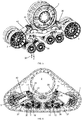
- Figure 1 gives an overall image of a track unit according to the first embodiment of the invention.
- the rotation of the track 1 is driven by the drive sprocket wheel 2 and furthermore guided to move over the terrain by front and rear guide wheels 3 and 4 (also called idler wheels), and by two bogies 5 and 6.
- Each guide wheel comprises two parallel wheels mounted on the same axis.
- Figure 2a illustrates the bogie 5 or 6 in more detail.
- the bogie comprises two pairs of bogie wheels 10, the wheels of each pair being mounted on either side of the bogie's longitudinal axis 15.
- the bogie comprises a central longitudinally arranged portion 11, that is rotatably mounted on a non-rotatable axle 12 oriented in the direction of transversal axis 13, extending between the two pairs of bogie wheels 10.
- the longitudinal portion 11 is rotatable about said transversal axis 13.
- a transversal axle portion 14 is mounted, each axle portion 14 being rotatable - with respect to the central longitudinal portion 11 - about the bogie's longitudinal axis 15.
- the wheels 10 are rotatably mounted on the ends of the transversal axle portions 14.
- the wheels 10 of the bogies are mounted lower than the guide wheels 3 and 4 so that in operation only the bogie wheels 10 are in contact with the ground.
- the track shown in Figure 1 thus comprises two parallel front guide wheels 3, two parallel rear guide wheels 4 and eight bogie wheels, arranged four by four on two independently suspended bogies 5 and 6. With the guide wheels 3, 4 above the suspended bogies 5, 6, they do not need to be suspended too. Such a set up may lead to less wear and easier climbing in tough conditions.
- the longitudinal portion's 11 freedom to rotate about the transversal axis 13 provides for the ability of each bogie to adapt to an unevenness of the terrain causing a longitudinal oscillation of the bogie (indicated by arrow 20).
- the transversal axle portions' 14 freedom to rotate about the longitudinal axis 15 provides for the ability of each individual bogie to adapt to an unevenness of the terrain causing a transversal oscillation of the bogie (indicated by arrow 21).
- the rotation axes 13 and 15 are preferably located in the same horizontal plane, horizontal being defined as the orientation of the longitudinal axis 15 when the bogie is placed on an essentially flat horizontal surface.
- the bogies 5 and 6 are suspended independently from each other from the chassis 35 of the track unit.
- the suspension of each bogie to the chassis 35 is illustrated in Figures 5 and 6 .
- a support bracket 36 is mounted on the chassis. At one end, the bracket is mounted so as to be rotatable about transversal axis 37, located to one side of the bogie. Starting from said transversal axis, the bracket reaches over above the bogie, towards the middle section of the bogie, where the other end of the bracket is bolted by two bolt connections 38 to the outer ends of the non-rotating axle 12.
- the support bracket 36 is connected to the movable end 40 of a hydraulic adjustable length actuator 39.
- the non-movable end 41 of the said actuator is fixed to the chassis 35.
- the actuator 39 is configured to exert a downward force on the bogie.
- Another actuator 42 is visible in Figures 5 and 6 , configured to exert a tensioning force on the front guide wheel 3.
- a track unit of the invention is characterized in the first place by the freedom of the bogie wheels 10 to rotate about the longitudinal axis 15 of the bogie itself, so that each bogie is capable individually of adapting to transversal oscillations.
- each pair of wheels is rotatable separately about said axis (e.g. by the axle portions 14 in the embodiment of Figure 3 ), but alternatively, sets of more than two wheel pairs could be arranged to be rotatable simultaneously about the longitudinal axis 15.
- the preferred embodiment involves bogies which allow simultaneously:
- FIG. 7 to 9 An alternative development not covered by the subject-matter of the appended claims is shown in Figures 7 to 9 .
- This concerns a track unit comprising a track 1, a drive sprocket 2, front and rear guide wheels 3 and 4, and a 6-wheel bogie 5.
- a cutter 51 is non-rotatably mounted on the rear guide wheel 4, in a position where the guide wheel is in direct contact with the track, i.e.
- the guide wheel 4 in this particular embodiment is in fact a guide wheel assembly comprising a set of two parallel wheels 54 which are rotatable about a non-rotatable axle 53, via suitably mounted roller bearings 55, see Figure 8 .
- the cutter 51 is bolted to a circular plate 52 consisting of inner and outer portions 52'/52".
- the plate 52 may also be a single piece.
- the plate 52 is bolted to the end face of the non-rotatable axle 53 so as not to rotate together with the wheels 54.
- the cutter 51 is thereby immovably connected to the non-rotatable axle 53.
- a circular side-plate 56 is furthermore fixed to one of the wheels 54, i.e. side plate 56 rotates together with the wheels 54.
- the side plate 56 is concentric with the fixed plate 52 and has a larger diameter than said fixed plate 52.
- the side-plate 56 has :
- the cutter 51 itself (see Figure 9 ) is triangular in shape and extends radially outward from an edge section of the fixed plate 52 towards the track 1, with a base edge 62 fixed by bolts 63 to the fixed plate 52, a central portion 64 overlapping the ring-portion 58 of the side plate 56 and a tip portion 65 overlapping the side of the track 1.
- the cutter 51 and fixed plate 52 remain stationary in terms of rotation about the axle 53, while the track 1 and the side plate 56 rotate together with the guide wheel 54. Stalks and leaves that are caught between the wheel 54 and the rubber track are thus transported upward towards the position of the cutter 51 where they are cut by the edges of the cutter, so that an accumulation of crop material in the interior of the track unit is prevented.
- the central portion 64 of the cutter comprises slanted lateral strips 66 that are in close proximity to the side plate 56.
- the tip 65 is profiled outwardly with respect to the central portion 64, thereby following the profile of the track 1 with respect to the side plate 56.
- the tip portion 65 is equally provided with slanted side strips 67 which remain in close proximity to the side of the track 1 during operation of the track unit.
- the cutter assembly may differ in a number of details compared to the embodiment shown in the drawings.
- the location of the cutter may be chosen anywhere along the arc ⁇ shown in Figure 7 .
- the shape of the cutter 51 may differ from the triangular shape, as long as the cutter is configured to cut crop materials being transported upward to the location of the cutter.
Landscapes
- Engineering & Computer Science (AREA)
- Chemical & Material Sciences (AREA)
- Combustion & Propulsion (AREA)
- Transportation (AREA)
- Mechanical Engineering (AREA)
- Harvester Elements (AREA)
- Guiding Agricultural Machines (AREA)
- Tires In General (AREA)
- Agricultural Machines (AREA)
- Platform Screen Doors And Railroad Systems (AREA)
- Harvesting Machines For Root Crops (AREA)
- Harvesting Machines For Specific Crops (AREA)
Description
- The present invention is related to a rubber track unit for use in vehicles, in particular for agricultural machines such as combine harvesters.
- Depending on the type of terrain, agricultural machines may be mounted on wheels or on rubber tracks. In the latter case, at least one track unit is provided on each side of the machine, each unit comprising a drive sprocket mounted on one of the vehicle's axles, for driving the rotation of the track. A typical configuration is shown in
EP-A-2130749 , with the drive sprocket mounted centrally above a front and back guide wheel (also called idler wheel), and with a set of bogies equipped with bogie wheels arranged between the guide wheels. The track is in contact with the ground in the section defined by the guide wheels and the bogies. A degree of flexibility is required of the guide wheels and/or the bogies in order to prevent irregularities in the terrain from being transmitted to the drive axle and causing excessive strain thereon. Such flexibility is obtained in current track assemblies by a variety of measures, such as the use of flexible materials (as inEP-A-2130749 ), or the design of bogies which allow longitudinal oscillations of the bogie wheels, i.e. oscillations of said wheels about an axis that is oriented transversally to the vehicle's movement. An example of the latter solution is shown inUS-A-2007/0181351 . Although the latter design allows for transversal oscillations of the track unit as a whole, such transversal oscillations may still cause problems in terms of distributing the vehicle's weight, especially on highly uneven terrains. A further typical configuration is known fromUS5899543 . Another problem occurring in track-equipped harvesting machines is that crop materials such as stalks and leaves are caught between the guide wheels and the rubber track, in particular between the rear guide wheels and the track. The crop material is then transported upward and threatens to accumulate in the track unit. Friction with the rotating belt threatens to heat up the accumulated material, leading to a potential fire hazard. - The invention is related to a track unit and to a vehicle as described in the appended claims. The track unit according to a first embodiment of the invention comprises one or more bogies arranged between front and rear guide wheels. The bogies are provided with wheel pairs that are rotatably arranged about a longitudinal axis of the bogie itself, and are thereby capable of adapting individually to transversal oscillations caused by the terrain. Each pair of wheels is mounted on a separate axle portion.The bogies are furthermore equipped to adapt to longitudinal oscillations as well, by the longitudinal portion of the bogie being rotatable about a transversal axis.
- The invention is also related to a track unit wherein the first embodiment is applied.
-
-
Figure 1 shows a 3D-view of a track unit according to first embodiment of the invention. -
Figure 2a shows a 3D-view of a bogie in a track unit according to the first embodiment.Figure 2b shows the same bogie with one wheel removed, revealing a clearer picture of the components of the bogie. -
Figure 3 shows sectioned frontal, top and side views of the bogie according to the embodiment also illustrated inFigure 2 . -
Figure 4 shows a detail of the rotatable connection between an axle portion and the central longitudinal portion of a bogie in a track unit according to the embodiment ofFigure 2 . -
Figure 5 illustrates the suspension of the bogies in a track unit according to the first embodiment of the invention. -
Figure 6 shows a sectioned side-view of a track unit according to the embodiment ofFigure 5 , illustrating more in detail the suspension of the bogies. -
Figure 7 illustrates a track unit not covered by the claims of the present invention wherein a cutter is mounted on one of the guide wheels of the track unit. -
Figure 8 shows a detail of the cutter -
Figure 9 shows a detail of the cutter in a track unit. - Preferred embodiments will now be described with reference to the drawings. The detailed description is not limiting the scope of the invention, which is defined only by the appended claims.
-
Figure 1 gives an overall image of a track unit according to the first embodiment of the invention. The rotation of thetrack 1 is driven by thedrive sprocket wheel 2 and furthermore guided to move over the terrain by front andrear guide wheels 3 and 4 (also called idler wheels), and by twobogies Figure 2a illustrates thebogie bogie wheels 10, the wheels of each pair being mounted on either side of the bogie'slongitudinal axis 15. As seen inFigure 2b , the bogie comprises a central longitudinally arrangedportion 11, that is rotatably mounted on anon-rotatable axle 12 oriented in the direction oftransversal axis 13, extending between the two pairs ofbogie wheels 10. Thelongitudinal portion 11 is rotatable about saidtransversal axis 13. On both ends of thelongitudinal portion 11, atransversal axle portion 14 is mounted, eachaxle portion 14 being rotatable - with respect to the central longitudinal portion 11 - about the bogie'slongitudinal axis 15. Thewheels 10 are rotatably mounted on the ends of thetransversal axle portions 14. As seen inFigure 1 , thewheels 10 of the bogies are mounted lower than theguide wheels bogie wheels 10 are in contact with the ground. The track shown inFigure 1 thus comprises two parallelfront guide wheels 3, two parallelrear guide wheels 4 and eight bogie wheels, arranged four by four on two independently suspendedbogies guide wheels bogies - The longitudinal portion's 11 freedom to rotate about the
transversal axis 13 provides for the ability of each bogie to adapt to an unevenness of the terrain causing a longitudinal oscillation of the bogie (indicated by arrow 20). The transversal axle portions' 14 freedom to rotate about thelongitudinal axis 15 provides for the ability of each individual bogie to adapt to an unevenness of the terrain causing a transversal oscillation of the bogie (indicated by arrow 21). - The various components and their interrelationship is shown in more detail in the sectioned views shown in
Figure 3 . The attachment and/or rotation of parts with respect to other parts may be brought into practice by applying suitable bearing and attachment means known per se in the art. In the particular embodiment ofFigure 3 , the assembly of theaxle portions 14 onto thelongitudinal portion 11 is shown in detail inFigure 4 . Theaxle portion 14 rotates about thecentral portion 11 via a plain bearing 22 and an axial roller bearing 23 and is maintained axially by thebolt connection 24. Other suitable types of bearings can be used instead of the above-described bearing types. - The
rotation axes longitudinal axis 15 when the bogie is placed on an essentially flat horizontal surface. - The
bogies chassis 35 of the track unit. The suspension of each bogie to thechassis 35 is illustrated inFigures 5 and 6 . Asupport bracket 36 is mounted on the chassis. At one end, the bracket is mounted so as to be rotatable abouttransversal axis 37, located to one side of the bogie. Starting from said transversal axis, the bracket reaches over above the bogie, towards the middle section of the bogie, where the other end of the bracket is bolted by twobolt connections 38 to the outer ends of thenon-rotating axle 12. On top of thebolt connection 38, thesupport bracket 36 is connected to themovable end 40 of a hydraulicadjustable length actuator 39. Thenon-movable end 41 of the said actuator is fixed to thechassis 35. Theactuator 39 is configured to exert a downward force on the bogie. Anotheractuator 42 is visible inFigures 5 and 6 , configured to exert a tensioning force on thefront guide wheel 3. - The invention is not limited to the embodiment shown in the drawings. A track unit of the invention is characterized in the first place by the freedom of the
bogie wheels 10 to rotate about thelongitudinal axis 15 of the bogie itself, so that each bogie is capable individually of adapting to transversal oscillations. Preferably each pair of wheels is rotatable separately about said axis (e.g. by theaxle portions 14 in the embodiment ofFigure 3 ), but alternatively, sets of more than two wheel pairs could be arranged to be rotatable simultaneously about thelongitudinal axis 15. The preferred embodiment involves bogies which allow simultaneously: - the rotation of the wheel pairs about said
longitudinal axis 15 and - the rotation of the
longitudinal portion 11 onto which the wheels are mounted, about atransversal axis 13 extending between two pairs of wheels. - The most preferred option shows a bogie wherein the longitudinal and transversal axes are lying in the same horizontal plane as defined above for the embodiment shown in the drawings. Instead of a suspension of the bogies by
hydraulic actuators 39, pneumatic actuators or any other suitable suspension means may be used. An alternative development not covered by the subject-matter of the appended claims is shown inFigures 7 to 9 . This concerns a track unit comprising atrack 1, adrive sprocket 2, front andrear guide wheels wheel bogie 5. In the track unit according to this embodiment, acutter 51 is non-rotatably mounted on therear guide wheel 4, in a position where the guide wheel is in direct contact with the track, i.e. within the arc denoted as α inFigure 7 . Theguide wheel 4 in this particular embodiment is in fact a guide wheel assembly comprising a set of twoparallel wheels 54 which are rotatable about anon-rotatable axle 53, via suitably mountedroller bearings 55, seeFigure 8 . Thecutter 51 is bolted to acircular plate 52 consisting of inner and outer portions 52'/52". Theplate 52 may also be a single piece. Theplate 52 is bolted to the end face of thenon-rotatable axle 53 so as not to rotate together with thewheels 54. Thecutter 51 is thereby immovably connected to thenon-rotatable axle 53. A circular side-plate 56 is furthermore fixed to one of thewheels 54, i.e.side plate 56 rotates together with thewheels 54. Theside plate 56 is concentric with the fixedplate 52 and has a larger diameter than said fixedplate 52. The side-plate 56 has : - an outer ring-
portion 58 that extends radially outward from the fixedplate 52, while being arranged flush with said fixedplate 52, - an
inner ring portion 59 that is bolted to the wheels viabolts 57, while lying inward axially with respect to the fixed plate 52 (i.e. underneath said fixed plate 52), - a
conical portion 60 that connects the outer andinner ring portions 58/59. The rim of the fixedplate 52 has aconical surface 61 at the side that faces the edge of theconical portion 60 of the side-plate 56. The clearance between the fixedplate 52 and theside plate 56 along said conical surface is small enough to prevent crop material from entering said clearance and large enough to allow the rotation of theside plate 56 with respect to the fixedplate 52. - The
cutter 51 itself (seeFigure 9 ) is triangular in shape and extends radially outward from an edge section of the fixedplate 52 towards thetrack 1, with abase edge 62 fixed bybolts 63 to the fixedplate 52, acentral portion 64 overlapping the ring-portion 58 of theside plate 56 and atip portion 65 overlapping the side of thetrack 1. During movement of the track unit, thecutter 51 and fixedplate 52 remain stationary in terms of rotation about theaxle 53, while thetrack 1 and theside plate 56 rotate together with theguide wheel 54. Stalks and leaves that are caught between thewheel 54 and the rubber track are thus transported upward towards the position of thecutter 51 where they are cut by the edges of the cutter, so that an accumulation of crop material in the interior of the track unit is prevented. - In the embodiment shown, the
central portion 64 of the cutter comprises slanted lateral strips 66 that are in close proximity to theside plate 56. Thetip 65 is profiled outwardly with respect to thecentral portion 64, thereby following the profile of thetrack 1 with respect to theside plate 56. Thetip portion 65 is equally provided with slanted side strips 67 which remain in close proximity to the side of thetrack 1 during operation of the track unit. - The cutter assembly may differ in a number of details compared to the embodiment shown in the drawings. The location of the cutter may be chosen anywhere along the arc α shown in
Figure 7 . The shape of thecutter 51 may differ from the triangular shape, as long as the cutter is configured to cut crop materials being transported upward to the location of the cutter.
Claims (7)
- A track unit for a vehicle, comprising a track (1), a chassis (35), a drive sprocket (2), multiple guide wheels (3,4), and one or more bogies (5,6), said bogies comprising at least two pairs of wheels (10), the wheels of each pair being mounted on either side of a longitudinal portion (11) of the bogie arranged along a longitudinal axis (15) of the bogie, wherein the wheels of each pair are mounted on a transversal axle portion (14), said axle portion being rotatable about said longitudinal axis (15), with respect to said longitudinal portion (11), characterized in that each pair of wheels (10) is mounted on a separate axle portion (14) and said longitudinal portion (11) is rotatable about a transversal axis (13) extending between two pairs of wheels (10) of the bogie.
- Track unit according to claim 1, comprising multiple bogies (5,6) suspended from the chassis (35), said bogies being suspended independently from each other.
- Track unit according to claim 1, wherein said longitudinal axis (15) and said transversal axis (13) are lying in the same horizontal plane.
- Track unit according to any one of the claims 1 to 3, wherein said longitudinal portion (11) is rotatable about a non-rotatable axle (12) oriented along said transversal axis (13), said non-rotatable axle (12) being fixed to a first end of a support bracket (36), with the opposite end of said support bracket being rotatably mounted on the chassis (35) of the track unit, so as to be rotatable about an axis (37) lying to one side of the bogie, and wherein a variable length actuator (39) is mounted between said first end of the bracket (36) and the chassis (35).
- Track unit according to any one of claims 1 to 4, wherein each bogie (5,6) comprises 2 pairs of wheels (10).
- Track unit according to any one of the preceding claims, said multiple guide wheels comprising a front and rear guide wheel (3,4), wherein a cutter (51) is non-rotatably mounted on one or both outer faces of the rear guide wheel (4), in a position where said rear guide wheel is in direct contact with the track (1), the cutter being configured to cut crop material that is transported upwards between the rear guide wheel (49) and the track (1) when the track unit moves forward.
- An agricultural vehicle equipped with one or more track units according to any one of the preceding claims.
Applications Claiming Priority (2)
| Application Number | Priority Date | Filing Date | Title |
|---|---|---|---|
| BE2013/0395A BE1021152B1 (en) | 2013-06-05 | 2013-06-05 | RUBBER CATERPILLAR UNIT FOR VEHICLE |
| PCT/EP2014/061648 WO2014195386A1 (en) | 2013-06-05 | 2014-06-05 | Rubber track unit for vehicle |
Publications (2)
| Publication Number | Publication Date |
|---|---|
| EP3003841A1 EP3003841A1 (en) | 2016-04-13 |
| EP3003841B1 true EP3003841B1 (en) | 2018-02-14 |
Family
ID=49035220
Family Applications (1)
| Application Number | Title | Priority Date | Filing Date |
|---|---|---|---|
| EP14727847.7A Active EP3003841B1 (en) | 2013-06-05 | 2014-06-05 | Rubber track unit for vehicle |
Country Status (9)
| Country | Link |
|---|---|
| US (2) | US10308296B2 (en) |
| EP (1) | EP3003841B1 (en) |
| CN (1) | CN105073567B (en) |
| AU (1) | AU2014276848B2 (en) |
| BE (1) | BE1021152B1 (en) |
| BR (1) | BR112015030316B1 (en) |
| CA (1) | CA2895432C (en) |
| RU (1) | RU2628271C2 (en) |
| WO (1) | WO2014195386A1 (en) |
Families Citing this family (25)
| Publication number | Priority date | Publication date | Assignee | Title |
|---|---|---|---|---|
| US9505454B1 (en) | 2011-06-13 | 2016-11-29 | Camso Inc. | Track assembly for traction of an off-road vehicle |
| BE1021152B1 (en) * | 2013-06-05 | 2016-01-13 | Cnh Industrial Belgium Nv | RUBBER CATERPILLAR UNIT FOR VEHICLE |
| US9415818B1 (en) * | 2015-02-18 | 2016-08-16 | Ati, Inc. | Track-module apparatus with load-independent load distribution |
| US10065690B2 (en) * | 2015-04-03 | 2018-09-04 | Harris Corporation | Conformal suspension for unmanned ground vehicle |
| US10875591B2 (en) | 2015-08-04 | 2020-12-29 | Camso Inc. | Track system for traction of an agricultural vehicle travelling on fields and roads |
| CN105438296B (en) * | 2015-12-24 | 2017-09-26 | 重庆太初新能源有限公司 | Track rail assembly after single-chain transmission |
| CN107351931A (en) * | 2017-08-21 | 2017-11-17 | 江苏中天引控智能系统有限公司 | A kind of antiwind inducer |
| CN108045446A (en) * | 2017-12-18 | 2018-05-18 | 南京航空航天大学 | A kind of two-wheel edge endless-track vehicle mechanical elasticity bogie wheel and its method of work |
| EP3556579B1 (en) * | 2018-04-19 | 2022-02-09 | NAF Neunkirchener Achsenfabrik AG | Bogie for a forestry vehicle and vehicle with at least one bogie axle |
| CN110682974B (en) * | 2018-07-04 | 2022-05-24 | 克拉斯工业技术有限责任公司 | Driving wheel for crawler type travelling mechanism |
| CN108674506A (en) * | 2018-07-25 | 2018-10-19 | 徐工集团工程机械有限公司 | Vehicle track running gear |
| CN108674504B (en) * | 2018-07-25 | 2023-12-08 | 江苏徐工工程机械研究院有限公司 | Modular track units for vehicles |
| CN108858123A (en) * | 2018-08-30 | 2018-11-23 | 重庆工程职业技术学院 | Scout car based on computer control |
| CA3135871A1 (en) | 2019-04-03 | 2020-10-08 | Camso Inc. | Wheel of track system for traction of a vehicle |
| US11618515B2 (en) | 2019-04-09 | 2023-04-04 | Cnh Industrial America Llc | Suspension system for a track-driven work vehicle with tandem rear idler/roller |
| US11753093B2 (en) | 2019-04-09 | 2023-09-12 | Cnh Industrial America Llc | Suspension system for a track-driven work vehicle with pivoting roller wheel assemblies |
| CN110481660A (en) * | 2019-09-24 | 2019-11-22 | 履地科技(天津)有限公司 | A kind of self-balancing bogie wheel group for rubber belt track running gear |
| CA3163884A1 (en) * | 2019-12-06 | 2021-06-10 | Camso Inc. | Track system for traction of a vehicle |
| US12091110B2 (en) | 2020-09-18 | 2024-09-17 | Soucy International Inc. | Support structure for connecting at least one support wheel assembly to a frame member of a track system and track system having the same |
| CA3131066A1 (en) | 2020-09-18 | 2022-03-18 | Soucy International Inc. | Support structure for connecting at least one support wheel assembly to a frame of a track system and track system having the same |
| CN112896348A (en) * | 2020-12-31 | 2021-06-04 | 徐州燕大传动与控制技术有限公司 | Automatic navigation three-point leveling type hydraulic active suspension chassis |
| US12391321B2 (en) | 2022-01-17 | 2025-08-19 | Unverferth Manufacturing Co., Inc. | Track configuration for a farm implement |
| CN115535100A (en) * | 2022-11-22 | 2022-12-30 | 成都倒立摆科技有限公司 | A single-shaft support track wheel without transmission clearance |
| US12576929B2 (en) | 2023-04-19 | 2026-03-17 | Shandong America Industries, Inc. | Endless track assembly |
| CN117022478A (en) * | 2023-10-07 | 2023-11-10 | 黑龙江省润昌农业机械有限公司 | High-speed crawler wheel assembly matched with large harvester and walking in imitation terrain |
Family Cites Families (31)
| Publication number | Priority date | Publication date | Assignee | Title |
|---|---|---|---|---|
| FR523157A (en) | 1920-08-28 | 1921-08-13 | Adolphe Kegresse | Mechanisms for the practical use of flexible tracks |
| US1725817A (en) * | 1925-02-25 | 1929-08-27 | Harnischfeger Corp | Flexible-tread truck |
| US2442354A (en) * | 1945-07-10 | 1948-06-01 | Jr John J Gordon | Dual wheel suspension for tracklaying vehicles |
| US3841424A (en) * | 1971-12-27 | 1974-10-15 | Caterpillar Tractor Co | Triangular track resilient bogie suspension |
| US3861762A (en) * | 1973-10-17 | 1975-01-21 | Caterpillar Tractor Co | Guard and scraper for an idler wheel |
| GB1565648A (en) * | 1975-09-02 | 1980-04-23 | Massey Ferguson Services Nv | Joints |
| DE2949942A1 (en) | 1979-12-12 | 1981-06-19 | Stekovič 2000 Hamburg Vaso | Non skid car wheel replacement - has rubber ribs on links of chain running on driven and idler sprockets arranged in triangle pattern |
| US4681177A (en) * | 1985-12-09 | 1987-07-21 | Caterpillar Inc. | Method and apparatus for tensioning frictionally driven, ground engaging belts |
| SU1691210A1 (en) | 1989-09-11 | 1991-11-15 | Московский Институт Нефти И Газа Им.И.М.Губкина | Track roller |
| SU1751035A1 (en) * | 1990-08-16 | 1992-07-30 | Белорусский Политехнический Институт | Track-cleaning device of vehicle |
| US5409075A (en) * | 1993-11-12 | 1995-04-25 | Nieman; Donnie L. | Pneumatic suspension system for farm equipment |
| US5452949A (en) | 1993-12-13 | 1995-09-26 | Kelderman; Gary L. | Track system for vehicles |
| US5622234A (en) * | 1993-12-22 | 1997-04-22 | Deere & Company | Track suspension system and track gauge adjustment assembly |
| AU5782396A (en) * | 1996-04-03 | 1997-10-22 | Nikolai Vitalievich Borsch | Caterpillar propulsion system and vehicle based on said system |
| US5899543A (en) * | 1997-02-14 | 1999-05-04 | Case Corporation | Resilient support element for roller wheels of a rubber tracked vehicle |
| CN2395948Y (en) | 1999-09-30 | 2000-09-13 | 中国一拖集团有限公司 | Running system for caterpillar tractor |
| US7740084B2 (en) | 2000-05-02 | 2010-06-22 | Lyn Rosenboom | Agricultural implement frame, track assembly and cart |
| US7726749B2 (en) | 2001-05-02 | 2010-06-01 | Lyn Rosenboom | Track assembly with bogie wheel structure |
| US7380892B2 (en) | 2001-05-02 | 2008-06-03 | Lyn Rosenboom | Track assembly with idler wheels and cart incorporating same |
| AUPR663901A0 (en) * | 2001-07-26 | 2001-08-16 | Contarino, Aldo | Suspension and steering arrangement for a vehicle |
| US6712549B2 (en) * | 2002-07-09 | 2004-03-30 | Blaw-Knox Construction Equipment Corporation | Double-axis oscillating bogie wheels |
| US6921140B2 (en) * | 2003-08-28 | 2005-07-26 | Deere & Company | Cutter bar pivot attachment |
| CA2479388A1 (en) * | 2004-09-17 | 2006-03-17 | Guy Gaudreault | System used on tracks for crossing obstacles |
| CN2752135Y (en) | 2004-11-30 | 2006-01-18 | 中国人民解放军国防科学技术大学 | Adaptive regulating small size synthetic resin crawler belt tighting device |
| US7478688B2 (en) | 2005-11-14 | 2009-01-20 | Deere & Company | Anti-dive/squat suspension system |
| US7533741B2 (en) | 2006-02-09 | 2009-05-19 | Glen Brazier | Swivel mounted track frame |
| ITMN20080012A1 (en) | 2008-06-05 | 2009-12-06 | Tidue S R L | TRACKING MACHINE FOR WORKING MACHINE ON SOIL |
| JP5114344B2 (en) | 2008-08-27 | 2013-01-09 | 株式会社クボタ | Crawler travel device |
| CN102481958B (en) * | 2009-06-30 | 2015-03-25 | Soucy国际公司 | Track system |
| CA2878283C (en) | 2012-07-06 | 2020-07-21 | Mtd Products Inc | Suspension and lock-out systems for a tracked vehicle |
| BE1021152B1 (en) * | 2013-06-05 | 2016-01-13 | Cnh Industrial Belgium Nv | RUBBER CATERPILLAR UNIT FOR VEHICLE |
-
2013
- 2013-06-05 BE BE2013/0395A patent/BE1021152B1/en not_active IP Right Cessation
-
2014
- 2014-06-05 BR BR112015030316-1A patent/BR112015030316B1/en active IP Right Grant
- 2014-06-05 WO PCT/EP2014/061648 patent/WO2014195386A1/en not_active Ceased
- 2014-06-05 EP EP14727847.7A patent/EP3003841B1/en active Active
- 2014-06-05 AU AU2014276848A patent/AU2014276848B2/en active Active
- 2014-06-05 RU RU2015153571A patent/RU2628271C2/en active
- 2014-06-05 CA CA2895432A patent/CA2895432C/en active Active
- 2014-06-05 US US14/896,206 patent/US10308296B2/en active Active
- 2014-06-05 CN CN201480010260.5A patent/CN105073567B/en active Active
-
2019
- 2019-05-29 US US16/424,800 patent/US11214319B2/en active Active
Also Published As
| Publication number | Publication date |
|---|---|
| US20160121946A1 (en) | 2016-05-05 |
| CA2895432A1 (en) | 2014-12-11 |
| CN105073567B (en) | 2017-10-24 |
| US20190276101A1 (en) | 2019-09-12 |
| AU2014276848A1 (en) | 2015-07-09 |
| US10308296B2 (en) | 2019-06-04 |
| WO2014195386A1 (en) | 2014-12-11 |
| US11214319B2 (en) | 2022-01-04 |
| BR112015030316A2 (en) | 2017-07-25 |
| RU2015153571A (en) | 2017-07-17 |
| BE1021152B1 (en) | 2016-01-13 |
| CN105073567A (en) | 2015-11-18 |
| RU2628271C2 (en) | 2017-08-15 |
| AU2014276848B2 (en) | 2016-09-01 |
| EP3003841A1 (en) | 2016-04-13 |
| BR112015030316B1 (en) | 2022-01-18 |
| CA2895432C (en) | 2017-04-25 |
Similar Documents
| Publication | Publication Date | Title |
|---|---|---|
| US11214319B2 (en) | Rubber track unit for vehicle | |
| EP2873593B1 (en) | A support structure | |
| EP3371038B1 (en) | Tracked vehicle with articulating frame | |
| US8042629B2 (en) | Snow traction unit for vehicles | |
| CA2845003C (en) | Track-module apparatus and open drive wheel therefor | |
| KR101922270B1 (en) | Working vehicle | |
| US10214256B2 (en) | Adjustable and removable track assembly for a tractor | |
| WO2012029783A1 (en) | Work vehicle | |
| AU2014277741A1 (en) | Sugarcane harvesting machine | |
| US9694862B2 (en) | Work vehicle | |
| US20150183464A1 (en) | Torsional Suspensioned, Steerable, Oscillating and Propelling Axle Assembly | |
| JP5820630B2 (en) | Work vehicle | |
| DK2757003T3 (en) | Conveyer device for motor vehicles | |
| US11039581B2 (en) | Apparatus for use with a vehicle to reduce plant material | |
| US8534457B1 (en) | Control apparatus for conveyor of particulate material | |
| CA2769948C (en) | Control apparatus for conveyor of particulate material | |
| JP2013001128A (en) | Working vehicle | |
| JP2013001129A (en) | Working vehicle | |
| HK1196341B (en) | Track-module apparatus and open drive wheel therefor | |
| HK1196341A (en) | Track-module apparatus and open drive wheel therefor | |
| TH86705B (en) | Tracked drive system | |
| TH92146A (en) | Crawler drive device | |
| NZ620678B2 (en) | Track-module apparatus and open drive wheel therefor |
Legal Events
| Date | Code | Title | Description |
|---|---|---|---|
| PUAI | Public reference made under article 153(3) epc to a published international application that has entered the european phase |
Free format text: ORIGINAL CODE: 0009012 |
|
| 17P | Request for examination filed |
Effective date: 20160105 |
|
| AK | Designated contracting states |
Kind code of ref document: A1 Designated state(s): AL AT BE BG CH CY CZ DE DK EE ES FI FR GB GR HR HU IE IS IT LI LT LU LV MC MK MT NL NO PL PT RO RS SE SI SK SM TR |
|
| AX | Request for extension of the european patent |
Extension state: BA ME |
|
| DAX | Request for extension of the european patent (deleted) | ||
| GRAP | Despatch of communication of intention to grant a patent |
Free format text: ORIGINAL CODE: EPIDOSNIGR1 |
|
| STAA | Information on the status of an ep patent application or granted ep patent |
Free format text: STATUS: GRANT OF PATENT IS INTENDED |
|
| INTG | Intention to grant announced |
Effective date: 20170906 |
|
| GRAS | Grant fee paid |
Free format text: ORIGINAL CODE: EPIDOSNIGR3 |
|
| GRAA | (expected) grant |
Free format text: ORIGINAL CODE: 0009210 |
|
| STAA | Information on the status of an ep patent application or granted ep patent |
Free format text: STATUS: THE PATENT HAS BEEN GRANTED |
|
| AK | Designated contracting states |
Kind code of ref document: B1 Designated state(s): AL AT BE BG CH CY CZ DE DK EE ES FI FR GB GR HR HU IE IS IT LI LT LU LV MC MK MT NL NO PL PT RO RS SE SI SK SM TR |
|
| REG | Reference to a national code |
Ref country code: GB Ref legal event code: FG4D |
|
| REG | Reference to a national code |
Ref country code: CH Ref legal event code: EP |
|
| REG | Reference to a national code |
Ref country code: IE Ref legal event code: FG4D |
|
| REG | Reference to a national code |
Ref country code: DE Ref legal event code: R096 Ref document number: 602014020937 Country of ref document: DE Ref country code: AT Ref legal event code: REF Ref document number: 969668 Country of ref document: AT Kind code of ref document: T Effective date: 20180315 |
|
| REG | Reference to a national code |
Ref country code: FR Ref legal event code: PLFP Year of fee payment: 5 |
|
| REG | Reference to a national code |
Ref country code: NL Ref legal event code: MP Effective date: 20180214 |
|
| REG | Reference to a national code |
Ref country code: AT Ref legal event code: MK05 Ref document number: 969668 Country of ref document: AT Kind code of ref document: T Effective date: 20180214 |
|
| PG25 | Lapsed in a contracting state [announced via postgrant information from national office to epo] |
Ref country code: FI Free format text: LAPSE BECAUSE OF FAILURE TO SUBMIT A TRANSLATION OF THE DESCRIPTION OR TO PAY THE FEE WITHIN THE PRESCRIBED TIME-LIMIT Effective date: 20180214 Ref country code: HR Free format text: LAPSE BECAUSE OF FAILURE TO SUBMIT A TRANSLATION OF THE DESCRIPTION OR TO PAY THE FEE WITHIN THE PRESCRIBED TIME-LIMIT Effective date: 20180214 Ref country code: NO Free format text: LAPSE BECAUSE OF FAILURE TO SUBMIT A TRANSLATION OF THE DESCRIPTION OR TO PAY THE FEE WITHIN THE PRESCRIBED TIME-LIMIT Effective date: 20180514 Ref country code: ES Free format text: LAPSE BECAUSE OF FAILURE TO SUBMIT A TRANSLATION OF THE DESCRIPTION OR TO PAY THE FEE WITHIN THE PRESCRIBED TIME-LIMIT Effective date: 20180214 Ref country code: LT Free format text: LAPSE BECAUSE OF FAILURE TO SUBMIT A TRANSLATION OF THE DESCRIPTION OR TO PAY THE FEE WITHIN THE PRESCRIBED TIME-LIMIT Effective date: 20180214 Ref country code: CY Free format text: LAPSE BECAUSE OF FAILURE TO SUBMIT A TRANSLATION OF THE DESCRIPTION OR TO PAY THE FEE WITHIN THE PRESCRIBED TIME-LIMIT Effective date: 20180214 Ref country code: NL Free format text: LAPSE BECAUSE OF FAILURE TO SUBMIT A TRANSLATION OF THE DESCRIPTION OR TO PAY THE FEE WITHIN THE PRESCRIBED TIME-LIMIT Effective date: 20180214 |
|
| PG25 | Lapsed in a contracting state [announced via postgrant information from national office to epo] |
Ref country code: GR Free format text: LAPSE BECAUSE OF FAILURE TO SUBMIT A TRANSLATION OF THE DESCRIPTION OR TO PAY THE FEE WITHIN THE PRESCRIBED TIME-LIMIT Effective date: 20180515 Ref country code: BG Free format text: LAPSE BECAUSE OF FAILURE TO SUBMIT A TRANSLATION OF THE DESCRIPTION OR TO PAY THE FEE WITHIN THE PRESCRIBED TIME-LIMIT Effective date: 20180514 Ref country code: RS Free format text: LAPSE BECAUSE OF FAILURE TO SUBMIT A TRANSLATION OF THE DESCRIPTION OR TO PAY THE FEE WITHIN THE PRESCRIBED TIME-LIMIT Effective date: 20180214 Ref country code: LV Free format text: LAPSE BECAUSE OF FAILURE TO SUBMIT A TRANSLATION OF THE DESCRIPTION OR TO PAY THE FEE WITHIN THE PRESCRIBED TIME-LIMIT Effective date: 20180214 Ref country code: SE Free format text: LAPSE BECAUSE OF FAILURE TO SUBMIT A TRANSLATION OF THE DESCRIPTION OR TO PAY THE FEE WITHIN THE PRESCRIBED TIME-LIMIT Effective date: 20180214 Ref country code: AT Free format text: LAPSE BECAUSE OF FAILURE TO SUBMIT A TRANSLATION OF THE DESCRIPTION OR TO PAY THE FEE WITHIN THE PRESCRIBED TIME-LIMIT Effective date: 20180214 |
|
| PG25 | Lapsed in a contracting state [announced via postgrant information from national office to epo] |
Ref country code: EE Free format text: LAPSE BECAUSE OF FAILURE TO SUBMIT A TRANSLATION OF THE DESCRIPTION OR TO PAY THE FEE WITHIN THE PRESCRIBED TIME-LIMIT Effective date: 20180214 Ref country code: RO Free format text: LAPSE BECAUSE OF FAILURE TO SUBMIT A TRANSLATION OF THE DESCRIPTION OR TO PAY THE FEE WITHIN THE PRESCRIBED TIME-LIMIT Effective date: 20180214 Ref country code: AL Free format text: LAPSE BECAUSE OF FAILURE TO SUBMIT A TRANSLATION OF THE DESCRIPTION OR TO PAY THE FEE WITHIN THE PRESCRIBED TIME-LIMIT Effective date: 20180214 Ref country code: PL Free format text: LAPSE BECAUSE OF FAILURE TO SUBMIT A TRANSLATION OF THE DESCRIPTION OR TO PAY THE FEE WITHIN THE PRESCRIBED TIME-LIMIT Effective date: 20180214 |
|
| REG | Reference to a national code |
Ref country code: DE Ref legal event code: R097 Ref document number: 602014020937 Country of ref document: DE |
|
| PG25 | Lapsed in a contracting state [announced via postgrant information from national office to epo] |
Ref country code: CZ Free format text: LAPSE BECAUSE OF FAILURE TO SUBMIT A TRANSLATION OF THE DESCRIPTION OR TO PAY THE FEE WITHIN THE PRESCRIBED TIME-LIMIT Effective date: 20180214 Ref country code: SK Free format text: LAPSE BECAUSE OF FAILURE TO SUBMIT A TRANSLATION OF THE DESCRIPTION OR TO PAY THE FEE WITHIN THE PRESCRIBED TIME-LIMIT Effective date: 20180214 Ref country code: DK Free format text: LAPSE BECAUSE OF FAILURE TO SUBMIT A TRANSLATION OF THE DESCRIPTION OR TO PAY THE FEE WITHIN THE PRESCRIBED TIME-LIMIT Effective date: 20180214 Ref country code: SM Free format text: LAPSE BECAUSE OF FAILURE TO SUBMIT A TRANSLATION OF THE DESCRIPTION OR TO PAY THE FEE WITHIN THE PRESCRIBED TIME-LIMIT Effective date: 20180214 |
|
| PLBE | No opposition filed within time limit |
Free format text: ORIGINAL CODE: 0009261 |
|
| STAA | Information on the status of an ep patent application or granted ep patent |
Free format text: STATUS: NO OPPOSITION FILED WITHIN TIME LIMIT |
|
| 26N | No opposition filed |
Effective date: 20181115 |
|
| REG | Reference to a national code |
Ref country code: CH Ref legal event code: PL |
|
| PG25 | Lapsed in a contracting state [announced via postgrant information from national office to epo] |
Ref country code: SI Free format text: LAPSE BECAUSE OF FAILURE TO SUBMIT A TRANSLATION OF THE DESCRIPTION OR TO PAY THE FEE WITHIN THE PRESCRIBED TIME-LIMIT Effective date: 20180214 |
|
| REG | Reference to a national code |
Ref country code: IE Ref legal event code: MM4A |
|
| PG25 | Lapsed in a contracting state [announced via postgrant information from national office to epo] |
Ref country code: MC Free format text: LAPSE BECAUSE OF FAILURE TO SUBMIT A TRANSLATION OF THE DESCRIPTION OR TO PAY THE FEE WITHIN THE PRESCRIBED TIME-LIMIT Effective date: 20180214 Ref country code: LU Free format text: LAPSE BECAUSE OF NON-PAYMENT OF DUE FEES Effective date: 20180605 |
|
| PG25 | Lapsed in a contracting state [announced via postgrant information from national office to epo] |
Ref country code: IE Free format text: LAPSE BECAUSE OF NON-PAYMENT OF DUE FEES Effective date: 20180605 Ref country code: CH Free format text: LAPSE BECAUSE OF NON-PAYMENT OF DUE FEES Effective date: 20180630 Ref country code: LI Free format text: LAPSE BECAUSE OF NON-PAYMENT OF DUE FEES Effective date: 20180630 |
|
| PG25 | Lapsed in a contracting state [announced via postgrant information from national office to epo] |
Ref country code: MT Free format text: LAPSE BECAUSE OF NON-PAYMENT OF DUE FEES Effective date: 20180605 |
|
| PG25 | Lapsed in a contracting state [announced via postgrant information from national office to epo] |
Ref country code: TR Free format text: LAPSE BECAUSE OF FAILURE TO SUBMIT A TRANSLATION OF THE DESCRIPTION OR TO PAY THE FEE WITHIN THE PRESCRIBED TIME-LIMIT Effective date: 20180214 |
|
| PG25 | Lapsed in a contracting state [announced via postgrant information from national office to epo] |
Ref country code: PT Free format text: LAPSE BECAUSE OF FAILURE TO SUBMIT A TRANSLATION OF THE DESCRIPTION OR TO PAY THE FEE WITHIN THE PRESCRIBED TIME-LIMIT Effective date: 20180214 |
|
| PG25 | Lapsed in a contracting state [announced via postgrant information from national office to epo] |
Ref country code: MK Free format text: LAPSE BECAUSE OF NON-PAYMENT OF DUE FEES Effective date: 20180214 Ref country code: HU Free format text: LAPSE BECAUSE OF FAILURE TO SUBMIT A TRANSLATION OF THE DESCRIPTION OR TO PAY THE FEE WITHIN THE PRESCRIBED TIME-LIMIT; INVALID AB INITIO Effective date: 20140605 |
|
| PG25 | Lapsed in a contracting state [announced via postgrant information from national office to epo] |
Ref country code: IS Free format text: LAPSE BECAUSE OF FAILURE TO SUBMIT A TRANSLATION OF THE DESCRIPTION OR TO PAY THE FEE WITHIN THE PRESCRIBED TIME-LIMIT Effective date: 20180614 |
|
| PGFP | Annual fee paid to national office [announced via postgrant information from national office to epo] |
Ref country code: BE Payment date: 20230630 Year of fee payment: 10 |
|
| PG25 | Lapsed in a contracting state [announced via postgrant information from national office to epo] |
Ref country code: BE Free format text: LAPSE BECAUSE OF NON-PAYMENT OF DUE FEES Effective date: 20240630 |
|
| REG | Reference to a national code |
Ref country code: BE Ref legal event code: MM Effective date: 20240630 |
|
| PGFP | Annual fee paid to national office [announced via postgrant information from national office to epo] |
Ref country code: DE Payment date: 20250626 Year of fee payment: 12 |
|
| PGFP | Annual fee paid to national office [announced via postgrant information from national office to epo] |
Ref country code: GB Payment date: 20250618 Year of fee payment: 12 |
|
| PGFP | Annual fee paid to national office [announced via postgrant information from national office to epo] |
Ref country code: FR Payment date: 20250624 Year of fee payment: 12 |
|
| PGFP | Annual fee paid to national office [announced via postgrant information from national office to epo] |
Ref country code: IT Payment date: 20250623 Year of fee payment: 12 |