EP3003760B1 - Electric drive device for driving a motor vehicle - Google Patents
Electric drive device for driving a motor vehicle Download PDFInfo
- Publication number
- EP3003760B1 EP3003760B1 EP14804012.4A EP14804012A EP3003760B1 EP 3003760 B1 EP3003760 B1 EP 3003760B1 EP 14804012 A EP14804012 A EP 14804012A EP 3003760 B1 EP3003760 B1 EP 3003760B1
- Authority
- EP
- European Patent Office
- Prior art keywords
- housing
- drive arrangement
- electrical drive
- electric motor
- envelope surface
- Prior art date
- Legal status (The legal status is an assumption and is not a legal conclusion. Google has not performed a legal analysis and makes no representation as to the accuracy of the status listed.)
- Not-in-force
Links
Images


Classifications
-
- B—PERFORMING OPERATIONS; TRANSPORTING
- B60—VEHICLES IN GENERAL
- B60K—ARRANGEMENT OR MOUNTING OF PROPULSION UNITS OR OF TRANSMISSIONS IN VEHICLES; ARRANGEMENT OR MOUNTING OF PLURAL DIVERSE PRIME-MOVERS IN VEHICLES; AUXILIARY DRIVES FOR VEHICLES; INSTRUMENTATION OR DASHBOARDS FOR VEHICLES; ARRANGEMENTS IN CONNECTION WITH COOLING, AIR INTAKE, GAS EXHAUST OR FUEL SUPPLY OF PROPULSION UNITS IN VEHICLES
- B60K1/00—Arrangement or mounting of electrical propulsion units
-
- B—PERFORMING OPERATIONS; TRANSPORTING
- B60—VEHICLES IN GENERAL
- B60K—ARRANGEMENT OR MOUNTING OF PROPULSION UNITS OR OF TRANSMISSIONS IN VEHICLES; ARRANGEMENT OR MOUNTING OF PLURAL DIVERSE PRIME-MOVERS IN VEHICLES; AUXILIARY DRIVES FOR VEHICLES; INSTRUMENTATION OR DASHBOARDS FOR VEHICLES; ARRANGEMENTS IN CONNECTION WITH COOLING, AIR INTAKE, GAS EXHAUST OR FUEL SUPPLY OF PROPULSION UNITS IN VEHICLES
- B60K7/00—Disposition of motor in, or adjacent to, traction wheel
- B60K7/0007—Disposition of motor in, or adjacent to, traction wheel the motor being electric
-
- B—PERFORMING OPERATIONS; TRANSPORTING
- B60—VEHICLES IN GENERAL
- B60G—VEHICLE SUSPENSION ARRANGEMENTS
- B60G9/00—Resilient suspensions of a rigid axle or axle housing for two or more wheels
- B60G9/02—Resilient suspensions of a rigid axle or axle housing for two or more wheels the axle or housing being pivotally mounted on the vehicle, e.g. the pivotal axis being parallel to the longitudinal axis of the vehicle
-
- B—PERFORMING OPERATIONS; TRANSPORTING
- B60—VEHICLES IN GENERAL
- B60K—ARRANGEMENT OR MOUNTING OF PROPULSION UNITS OR OF TRANSMISSIONS IN VEHICLES; ARRANGEMENT OR MOUNTING OF PLURAL DIVERSE PRIME-MOVERS IN VEHICLES; AUXILIARY DRIVES FOR VEHICLES; INSTRUMENTATION OR DASHBOARDS FOR VEHICLES; ARRANGEMENTS IN CONNECTION WITH COOLING, AIR INTAKE, GAS EXHAUST OR FUEL SUPPLY OF PROPULSION UNITS IN VEHICLES
- B60K6/00—Arrangement or mounting of plural diverse prime-movers for mutual or common propulsion, e.g. hybrid propulsion systems comprising electric motors and internal combustion engines
- B60K6/20—Arrangement or mounting of plural diverse prime-movers for mutual or common propulsion, e.g. hybrid propulsion systems comprising electric motors and internal combustion engines the prime-movers consisting of electric motors and internal combustion engines, e.g. HEVs
- B60K6/22—Arrangement or mounting of plural diverse prime-movers for mutual or common propulsion, e.g. hybrid propulsion systems comprising electric motors and internal combustion engines the prime-movers consisting of electric motors and internal combustion engines, e.g. HEVs characterised by apparatus, components or means specially adapted for HEVs
- B60K6/40—Arrangement or mounting of plural diverse prime-movers for mutual or common propulsion, e.g. hybrid propulsion systems comprising electric motors and internal combustion engines the prime-movers consisting of electric motors and internal combustion engines, e.g. HEVs characterised by apparatus, components or means specially adapted for HEVs characterised by the assembly or relative disposition of components
- B60K6/405—Housings
-
- H—ELECTRICITY
- H02—GENERATION; CONVERSION OR DISTRIBUTION OF ELECTRIC POWER
- H02K—DYNAMO-ELECTRIC MACHINES
- H02K5/00—Casings; Enclosures; Supports
-
- H—ELECTRICITY
- H02—GENERATION; CONVERSION OR DISTRIBUTION OF ELECTRIC POWER
- H02K—DYNAMO-ELECTRIC MACHINES
- H02K5/00—Casings; Enclosures; Supports
- H02K5/04—Casings or enclosures characterised by the shape, form or construction thereof
- H02K5/22—Auxiliary parts of casings not covered by groups H02K5/06-H02K5/20, e.g. shaped to form connection boxes or terminal boxes
-
- H—ELECTRICITY
- H02—GENERATION; CONVERSION OR DISTRIBUTION OF ELECTRIC POWER
- H02K—DYNAMO-ELECTRIC MACHINES
- H02K7/00—Arrangements for handling mechanical energy structurally associated with dynamo-electric machines, e.g. structural association with mechanical driving motors or auxiliary dynamo-electric machines
- H02K7/003—Couplings; Details of shafts
-
- B—PERFORMING OPERATIONS; TRANSPORTING
- B60—VEHICLES IN GENERAL
- B60G—VEHICLE SUSPENSION ARRANGEMENTS
- B60G2200/00—Indexing codes relating to suspension types
- B60G2200/30—Rigid axle suspensions
- B60G2200/32—Rigid axle suspensions pivoted
- B60G2200/322—Rigid axle suspensions pivoted with a single pivot point and a straight axle
-
- B—PERFORMING OPERATIONS; TRANSPORTING
- B60—VEHICLES IN GENERAL
- B60G—VEHICLE SUSPENSION ARRANGEMENTS
- B60G2300/00—Indexing codes relating to the type of vehicle
- B60G2300/50—Electric vehicles; Hybrid vehicles
-
- B—PERFORMING OPERATIONS; TRANSPORTING
- B60—VEHICLES IN GENERAL
- B60K—ARRANGEMENT OR MOUNTING OF PROPULSION UNITS OR OF TRANSMISSIONS IN VEHICLES; ARRANGEMENT OR MOUNTING OF PLURAL DIVERSE PRIME-MOVERS IN VEHICLES; AUXILIARY DRIVES FOR VEHICLES; INSTRUMENTATION OR DASHBOARDS FOR VEHICLES; ARRANGEMENTS IN CONNECTION WITH COOLING, AIR INTAKE, GAS EXHAUST OR FUEL SUPPLY OF PROPULSION UNITS IN VEHICLES
- B60K11/00—Arrangement in connection with cooling of propulsion units
- B60K11/02—Arrangement in connection with cooling of propulsion units with liquid cooling
-
- B—PERFORMING OPERATIONS; TRANSPORTING
- B60—VEHICLES IN GENERAL
- B60K—ARRANGEMENT OR MOUNTING OF PROPULSION UNITS OR OF TRANSMISSIONS IN VEHICLES; ARRANGEMENT OR MOUNTING OF PLURAL DIVERSE PRIME-MOVERS IN VEHICLES; AUXILIARY DRIVES FOR VEHICLES; INSTRUMENTATION OR DASHBOARDS FOR VEHICLES; ARRANGEMENTS IN CONNECTION WITH COOLING, AIR INTAKE, GAS EXHAUST OR FUEL SUPPLY OF PROPULSION UNITS IN VEHICLES
- B60K1/00—Arrangement or mounting of electrical propulsion units
- B60K2001/001—Arrangement or mounting of electrical propulsion units one motor mounted on a propulsion axle for rotating right and left wheels of this axle
-
- B—PERFORMING OPERATIONS; TRANSPORTING
- B60—VEHICLES IN GENERAL
- B60K—ARRANGEMENT OR MOUNTING OF PROPULSION UNITS OR OF TRANSMISSIONS IN VEHICLES; ARRANGEMENT OR MOUNTING OF PLURAL DIVERSE PRIME-MOVERS IN VEHICLES; AUXILIARY DRIVES FOR VEHICLES; INSTRUMENTATION OR DASHBOARDS FOR VEHICLES; ARRANGEMENTS IN CONNECTION WITH COOLING, AIR INTAKE, GAS EXHAUST OR FUEL SUPPLY OF PROPULSION UNITS IN VEHICLES
- B60K1/00—Arrangement or mounting of electrical propulsion units
- B60K2001/003—Arrangement or mounting of electrical propulsion units with means for cooling the electrical propulsion units
- B60K2001/006—Arrangement or mounting of electrical propulsion units with means for cooling the electrical propulsion units the electric motors
-
- B—PERFORMING OPERATIONS; TRANSPORTING
- B60—VEHICLES IN GENERAL
- B60K—ARRANGEMENT OR MOUNTING OF PROPULSION UNITS OR OF TRANSMISSIONS IN VEHICLES; ARRANGEMENT OR MOUNTING OF PLURAL DIVERSE PRIME-MOVERS IN VEHICLES; AUXILIARY DRIVES FOR VEHICLES; INSTRUMENTATION OR DASHBOARDS FOR VEHICLES; ARRANGEMENTS IN CONNECTION WITH COOLING, AIR INTAKE, GAS EXHAUST OR FUEL SUPPLY OF PROPULSION UNITS IN VEHICLES
- B60K7/00—Disposition of motor in, or adjacent to, traction wheel
- B60K2007/0061—Disposition of motor in, or adjacent to, traction wheel the motor axle being parallel to the wheel axle
-
- B—PERFORMING OPERATIONS; TRANSPORTING
- B60—VEHICLES IN GENERAL
- B60K—ARRANGEMENT OR MOUNTING OF PROPULSION UNITS OR OF TRANSMISSIONS IN VEHICLES; ARRANGEMENT OR MOUNTING OF PLURAL DIVERSE PRIME-MOVERS IN VEHICLES; AUXILIARY DRIVES FOR VEHICLES; INSTRUMENTATION OR DASHBOARDS FOR VEHICLES; ARRANGEMENTS IN CONNECTION WITH COOLING, AIR INTAKE, GAS EXHAUST OR FUEL SUPPLY OF PROPULSION UNITS IN VEHICLES
- B60K7/00—Disposition of motor in, or adjacent to, traction wheel
- B60K2007/0092—Disposition of motor in, or adjacent to, traction wheel the motor axle being coaxial to the wheel axle
-
- B—PERFORMING OPERATIONS; TRANSPORTING
- B60—VEHICLES IN GENERAL
- B60Y—INDEXING SCHEME RELATING TO ASPECTS CROSS-CUTTING VEHICLE TECHNOLOGY
- B60Y2200/00—Type of vehicle
- B60Y2200/40—Special vehicles
- B60Y2200/41—Construction vehicles, e.g. graders, excavators
-
- B—PERFORMING OPERATIONS; TRANSPORTING
- B60—VEHICLES IN GENERAL
- B60Y—INDEXING SCHEME RELATING TO ASPECTS CROSS-CUTTING VEHICLE TECHNOLOGY
- B60Y2306/00—Other features of vehicle sub-units
- B60Y2306/03—Lubrication
Definitions
- the invention relates to an electrical drive arrangement according to the preamble of claim 1.
- the invention also relates to a motor vehicle.
- the automotive industry is undergoing a period of change where the vehicles are electrified to a greater extension, where a trend is hybridization of different degree.
- WO2012066035 discloses an electric shaft of a motor vehicle comprising an electric motor for propulsion of the vehicle arranged coaxially on said shaft and hence transverse to the longitudinal extension of the vehicle.
- the electric shaft has transmission configurations on each side of the electric motor. Such an electrical shaft enables a compact and volume-efficient construction.
- An object of the present invention is to obtain an electrical drive arrangement for driving a motor vehicle with a compact and volume-efficient design that enables improved manoeuvrability of the motor vehicle.
- an electrical drive arrangement for driving a motor vehicle comprising an electric motor, a drive shaft driven by means of the electric motor, a housing in which the electric motor is accommodated, which housing has an envelope surface and a substantially annular cross section wherein the horizontal direction of the envelope surface of said housing and hereby said drive shaft are arranged to run substantially transverse to the longitudinal direction of said vehicle, comprising a pendulum suspension for suspension of the electrical drive arrangement, where the pendulum suspension comprises a fastening configuration fixedly connected to the vehicle and at least one pendulum attachment fixedly connected to the envelope surface of the housing and pivotally journaled relative to said fastening configuration by means of a bearing configuration.
- the electric motor has a stator and a rotor arranged to rotate the drive shaft.
- said drive shaft is arranged for driving two output shafts for driving ground engaging means, preferably via suitable transmission configurations and wherein said output shafts are arranged to run substantially transverse to the longitudinal direction of said vehicle.
- said fastening configuration is arranged for suspension of a front and a rear pendulum attachment. This results in a stable suspension of the electrical drive shaft arrangement.
- said bearing configuration comprises slide bearing.
- said slide bearing comprises an outer bearing part fixedly connected to said fastening configuration and an inner bearing part fixedly connected to said pendulum attachment and internally and slidable relative to said outer bearing part.
- said pendulum attachment is connected to a connection unit attached at the envelope surface of said housing for medium supply of the electric motor, wherein said medium supply is arranged to take place via an opening in the envelope surface of said housing.
- this enables, by medium supplying the electric motor via the connection unit in the form of energy supply from power electronics, providing of an axially compact electrical drive arrangement where the electrical drive arrangement comprises transmission configuration arranged on respective side of the electric motor since no cabling needs to be connected/disconnected on any of the sides of the electric motor to free up space at the ends for compact connection of the transmission configuration.
- the transmission configuration may be constituted by planetary gear/reduction gear.
- medium supplying the electric motor via the connection unit in the form of coolant and lubricant and, where proper, transmission configurations in the form of planetary gears/reduction gears simple and efficient cooling and lubrication of the electrical drive arrangement, and hence efficient operation, is enabled.
- connection unit is connected to said pendulum attachment inside the inner bearing part of said slide bearing. This minimizes the movement of the connection unit during rotation of the pendulum attachment relatively the fastening configuration wherein for instance cabling connected at the connection unit and clutched to fixed part of the vehicle is not affected/pivoted significantly during said rotation.
- said pendulum attachment is arranged between uppermost and lowermost portions of the envelope surface of said housing.
- the ground clearance of the vehicle or the height of the vehicle is not affected by the pendulum attachment, wherein such an embodiment of the electrical drive arrangement is well suited for, for instance, mining vehicles that move in confined spaces.
- said pendulum attachment axially is arranged substantially adjacent to a central portion of the envelope surface of said housing. This results in a stable pendulum suspension.
- the pendulum attachment circumferentially of the envelope surface of the housing is located adjacent to a horizontal centre plane of the envelope surface of the housing. This results in a stable pendulum suspension.
- said medium supply comprises energy supply by means of power electronics and/or coolant and lubricant supply.
- an oil sump is arranged at the bottom of the housing in a desired space formed between the electric motor and said housing under a lowermost portion of the envelope surface of the electric motor, for said coolant and lubricant supply. This enables for efficient lubrication of gears/cogwheels and uptaking of oil coolant for cooling the electric motor.
- the electric motor is eccentrically arranged in the housing such that the centre of rotation of the drive shaft of the electric motor runs substantially parallel to and spaced from an imaginary centre axis of the housing to form said desired space.
- the electrical drive arrangement further comprises a differential device having a shaft configuration arranged in the housing in the desired space between the electric motor and the housing.
- Fig. 1 schematically illustrates a motor vehicle 1 according to an embodiment of the present invention.
- the exemplified vehicle 1 is constituted by a heavy vehicle in the form of a work vehicle such as a mining vehicle.
- the vehicle is constituted by a military vehicle.
- the motor vehicle is constituted by an articulated vehicle.
- the motor vehicle 1 comprises an electrical drive arrangement I according to any of the embodiments of the present invention.
- the motor vehicle 1 is intended to be propelled by means of the drive arrangement.
- the motor vehicle 1 comprises a vehicle body 2 comprising a vehicle frame.
- the electrical drive arrangement I is arranged to drive output shafts 5.
- Hub means 6a, 6b are arranged at the end of the respective output shaft 5.
- hub means 6a, 6b are constituted by hub reductions 6a, 6b.
- the hub means are constituted by drive wheels for tracked vehicles, which in a variant comprise hub reduction gears.
- Ground engaging means 7a, 7b are arranged at the respective hub reduction 6a, 6b for propulsion of the vehicle 1.
- the ground engaging means 7a, 7b are constituted by wheels.
- the ground engaging means 7a, 7b are constituted by tracks.
- Said output shafts 5 are arranged to run substantially transverse to the longitudinal direction of the vehicle 1 intended to be driven by means of the electrical drive arrangement I.
- the electrical drive arrangement I comprises a housing 30 and an electric motor 20 accommodated in the housing 30 arranged to drive a drive shaft 26.
- said output shafts 5 are arranged substantially coaxially with said electric motor 20, i.e. aligned with the drive shaft 26 of the electric motor. This results in efficient operation of the vehicle 1.
- said drive shaft member 5 arranged radially displaced relative to said electric motor 20, where, in a variant, said output shafts 5 are radially displaced relative to the electric motor 20 such that the ground engaging means 7a, 7b are displaced forward in the longitudinal extension of the vehicle such that, among other things, overcoming of obstacles is improved.
- the electrical drive arrangement I comprises a pendulum suspension 70 for suspending the electrical drive arrangement I.
- the pendulum suspension 70 comprises a fastening configuration fixedly connected to the vehicle 1 and a pendulum attachment 76 fixedly connected to an envelope surface 31 of the housing 30 and pivotally journaled relative to said fastening configuration 72 by means of a bearing configuration 82.
- the electrical drive arrangement I is rotatable relative to the body 2 of the vehicle.
- the electrical drive arrangement I is intended to drive heavy vehicles, such as work vehicles.
- Fig. 2 schematically illustrates a plan view of a motor vehicle with the electrical drive arrangement I of Fig. 1 according to an embodiment of the present invention.
- the electrical drive shaft arrangement that here constitutes the rear driving shaft, is pendulum suspended while the front shaft is rigidly fastened in the frame of the vehicle. This improves the manoeuvrability of the vehicle.
- Fig. 3 schematically illustrates a front view of an electrical drive arrangement I according to an embodiment of the present invention, for instance an electrical drive arrangement I according to Figs. 1 and 2 , Fig. 4 a radial cross sectional view of the electrical drive arrangement I of the Fig. 3 and Fig. 5 a plan view of the electrical drive arrangement I of the Fig. 3 .
- the electrical drive arrangement I for driving a motor vehicle 1 comprises an electric motor 20 as well as a drive shaft 26 driven by means of the electric motor.
- the electric motor 20 has a substantially circular cylindrical shape.
- the electric motor 20 has an envelope surface 21.
- the electrical drive arrangement I further comprises a housing 30 in which the electric motor is accommodated.
- the housing has an envelope surface 31 and a substantially annular cross section.
- the horizontal direction of the envelope surface 31 of said housing 30 and hereby said drive shaft 26 are arranged to run substantially transverse to the longitudinal direction of said vehicle as shown in Fig. 1 and Fig. 2 .
- Said housing 30 is axially, i.e. transverse to the longitudinal direction of the vehicle, arranged substantially centrally of the vehicle and said output shafts 5.
- the electric motor 20 has a stator 22 and a rotor 24 arranged to rotate the drive shaft 26.
- Said drive shaft is arranged for driving said two output shafts 5 for driving the ground engaging means, preferably via suitable transmission configurations 50, 60.
- Said output shafts 5 are arranged to run substantially transversely to the longitudinal direction of said vehicle.
- the electrical drive arrangement I comprises transmission configurations 50, 60 arranged on both sides of the electric motor 20.
- the electrical drive arrangement I further comprises, as shown in Figs. 3 and 4 , a differential device 40 superposed arranged and connected to said transmission configurations 50, 60 for accomplishing of differential function.
- the electrical drive arrangement I further comprises a pendulum suspension 70 for suspending the electrical drive arrangement I.
- the pendulum suspension 70 comprises a fastening configuration 72 fixedly connected to the vehicle and a pendulum attachment 74, 76, fixedly connected to the envelope surface of the housing and pivotally journaled by means of a bearing configuration 80 relative to said fastening configuration 72, comprising a front pendulum attachment 74 and a rear pendulum attachment 76.
- the electrical drive arrangement I is rotatable relative to the body 2 of the vehicle.
- Said fastening configuration 72 is arranged for suspension of said front and rear pendulum attachment 74, 76.
- Said bearing configuration 80, 82 comprises slide bearing 80, 82.
- Said slide bearing comprises an outer bearing part 80a, 80b fixedly connected to said fastening configuration 72 and an inner bearing part 80b, 82b fixedly connected to said pendulum attachment 74, 76 and slidable internally and relative to said outer bearing part 80a, 80b.
- Said outer and inner bearing parts 80a, 80b, 80b, 82b constitute the bearing races for said pendulum suspension 70.
- One of said front and rear pendulum attachments 74, 76, here the front pendulum attachment 74, is connected to a connection unit 100 attached at the envelope surface 31 of said housing 30 for the medium supply of the electric motor 20 and transmission configuration 50, 60. Said medium supply is intended to take place via an opening in the envelope surface 31 of said housing 30.
- connection unit 100 is connected to said pendulum attachment 70 inside the inner bearing part 80b of said slide bearing 80.
- Said medium supply comprises energy supply by means of power electronics as well as coolant and lubricant supply.
- Said connection unit 100 comprises connection interface(s) 100a for connecting cabling for said power electronics and cabling for said coolant and lubricant supply. An embodiment of said connection interface(s) is described in more detail with reference to Figs. 6a and 6b .
- the envelope surface 31 of said housing 30 has an uppermost portion 30a and a lowermost portion 30b.
- Said pendulum attachment 74 is arranged between the uppermost and lowermost portions 30a, 30b of the envelope surface 31 of the housing 30.
- Said pendulum attachment 74 is axially arranged substantially adjacent to a central portion of the envelope surface 31 of said housing 30.
- Said pendulum attachment is circumferentially of the envelope surface 31 of the housing 30 located adjacent to a horizontal centre plane of the envelope surface 31 of the housing 30.
- the front pendulum attachment 74 is arranged on the front side of the envelope surface 31 of said housing 30 between the uppermost and lowermost portions of the envelope surface 31 of said housing 30, axially arranged substantially adjacent to a central portion of the envelope surface 31 of said housing 30, and circumferentially of the envelope surface 31 of the housing 30 located adjacent to a horizontal centre plane of the envelope surface 31 of the housing 30.
- the rear pendulum attachment 76 is arranged on the rear side of the envelope surface 31 of said housing 30 between the uppermost and lowermost portions 30a, 30b of the envelope surface 31 of said housing 30, axially arranged substantially adjacent to a central portion of the envelope surface 31 of said housing 30, and circumferentially of the envelope surface 31 of the housing 30, located adjacent to a horizontal centre plane of the envelope surface 31 of the housing 30.
- the rear pendulum attachment 76 is arranged at the envelope surface 31 of the housing 30 substantially opposed to and aligned with the front pendulum attachment 74 such that an imaginary axis Y between the front pendulum attachment and the rear pendulum attachment, i.e.
- connection unit 100 is arranged on the front side of the envelope surface 31 of said housing 30 between the uppermost and lowermost portions 30a, 30b of the envelope surface 31 of said housing 30, axially arranged substantially adjacent to a central portion of the envelope surface 31 of said housing 30, and circumferentially of the envelope surface 31 of the housing 30 located adjacent to a horizontal centre plane of the envelope surface 31 of the housing 30.
- connection unit 100 By arranging the connection unit 100 between the uppermost and lowermost portions 30a, 30b of the envelope surface 31, the ground clearance of the vehicle is not affected by the connection unit 100 nor the height of the vehicle. Further, in a variant, the connection unit 100 is arranged adjacent the envelope surface 31 of the housing 30 such that splashes, in the form of, for instance, stones, gravel, mud and/or water ripped from ground engaging means connected to other drive shafts such as wheels, are not ending up on the connection unit 100.
- Said bearing configuration 80, 82 comprises a front slide bearing 80 having an outer bearing part 80a fixedly connected to said fastening configuration 72 and an inner bearing part 80b fixedly connected to said front pendulum attachment 74 and slidable internally and relative to said outer bearing part 80a.
- Said bearing configuration 80, 82 comprises a rear slide bearing 82 having an outer bearing part 82a fixedly connected to said fastening configuration 72 and an inner bearing part 82b fixedly connected to said rear pendulum attachment 76 and slidable internally and relative to said outer bearing part 82a.
- the fastening configuration 72 comprises a front fastening portion 72a and a rear fastening portion 72b.
- the front fastening portion 72a is arranged in front of the housing 30 and the rear fastening portion 72b is arranged behind the housing 30.
- the front fastening portion 72a is at an end region fixedly connected to the body 2/chassis 2/frame 2 of the vehicle and at an opposed end region fixedly connected to the outer bearing part 80a of the front slide bearing 80.
- the rear fastening portion 72b is at an end region fixedly connected to the body 2/chassis 2/frame 2 of the vehicle and at an opposed end region fixedly connected to the outer bearing part 82a of the rear slide bearing 82.
- said medium supply comprises electrical energy supply as well as coolant and lubricant supply.
- the connection unit 100 is configured for connection of cabling 105 for electric energy supply as well as lines 101, 102a, 102b, 104a, 104b for coolant and lubricant.
- said medium supply is arranged to take place via the connection unit 100 that is arranged adjacent to the envelope surface of the housing inside the inner portion of the bearing configuration.
- connection unit 100 comprises connection interface(s) for cabling for said electrical energy supply.
- connection unit 100 comprises connection interface(s) for connection of line configuration for pumping, by means of a not shown pumping unit, coolant and lubricant for coolant and lubricant supply of the transmission configuration 50, 60 and the electric motor.
- the line configuration comprises an uptake line 101 for taking up oil from the oil sump for pumping via heat exchangers returning via the connection unit 100 for supplying the electric motor 20 and the transmission configurations 50, 60.
- the connection unit 100 comprises connection interface(s) for said coolant and lubrication lines 101, 102a, 102b, 104a, 104b intended for transportation of coolant and lubricant for cooling and lubrication of the electric motor 20 and the transmission configurations 50, 60.
- Said cooling and lubrication lines are arranged to be led via said transmission configurations 50, 60 for lubrication of gears of the transmission configuration by means of the lubricant, and about the envelope 21 of the electric motor 20 for cooling the electric motor 20 by means of the coolant, where, in an embodiment, the lubricant and the coolant are constituted by oil from the same source in the form of the oil sump O.
- An axially running space 36 under the envelope surface of the electric motor 20 is utilized as oil sump O.
- the volume becomes available by that the electric motor 20 is eccentrically arranged relative to the housing 30.
- the space 36 provides room for the shaft configuration 42a, 42b of the differential device described with reference to Figs. 7a and 7b , and consequently to a differential brake/torque-vectoring not shown.
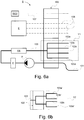
- Fig. 6a schematically illustrates a system S for supply of supply means via a connection unit of the electrical drive arrangement I according to an embodiment of the present invention.
- the system comprises said connection unit 100.
- the system further comprises a pump unit P arranged to, in a line configuration, pump coolant and lubricant, in a variant oil, from a space at the bottom of the housing of the electrical drive arrangement I, according to the present invention, by an uptake line 101 via said connection unit 100.
- the system S further comprises a filter member F arranged downstream of the pump unit P and configured to filter coolant and lubricant pumped from the space.
- the system S further comprises a heat exchanger HX arranged downstream of the pump unit P and configured to cool heated coolant and lubricant.
- the line configuration comprises an inlet line 103, arranged downstream of the heat exchanger HX, which is connected to the connection unit 100 for supply of coolant and lubricant to the transmission configuration and the electric motor.
- Said inlet line 103 is connected to the connection unit 100 branched into a set of supply lines 103a, 103b, 103c, 103d for enabling priority of supply of the transmission configuration and the electric motor.
- connection unit 100 comprises not shown overflow valves that are arranged to open based on a predetermined pressure.
- the priority of supply is arranged to take place such that the transmission configurations, in a variant planetary gears arranged on either side of the electric motor, as well as the differential configuration, first are provided with coolant and lubricant via a first supply line 103a of the set of supply lines 103a, 103b, 103c, 103d, and then winding-heads of the stator winding of the electric motor are provided with coolant and lubricant via a second supply line 103b, whereby then a third supply line 103c is activated for providing the electric motor rotor with coolant and lubricant, and then the envelope of the electric motor is provided with coolant and lubricant, as well as also bearings.
- the performance of the pump unit P is impaired, wherein the accessibility of the vehicle is ensured in that the risk of failed transmission configurations is avoided.
- cooled oil is intended to by high pressure be led in the inlet line 103 into the connection unit 100, branched into the set supply lines 103a, 103b, 103c, 103d by prioritizing for instance as above.
- Oil heated by the electric motor and the transmission configuration is then pumped up from the oil sump in the bottom of the housing and is led via the connection unit 100 and via the pump unit P through the filter F and via the heat exchanger HX for cooling the oil and then returning through the inlet line for supplying the transmission configuration and the electric motor.
- the system S further comprises power electronics E arranged to electrically energy supply the electric motor.
- Said power electronics E is connected to the electric motor via the cabling 105 in the form of three-phase line, which cabling is connected to the electric motor via the connection unit 100.
- the system also comprises an electronic control unit ECU.
- the electronic control unit ECU is arranged to receive signals from a signal line configuration 107 via the connection unit 100.
- the electronic control unit is arranged to receive signals from not shown sensor means arranged in connection with electrical drive unit of the electrical drive arrangement I according to the present invention, where said sensor means may comprise flow sensor(s) for determining the flow rate of the coolant and lubricant, level sensor(s) for determining coolant and lubricant level of the oil sump, pressure sensor(s) for determining the pressure of the coolant and lubricant, temperature sensor(s) for determining the temperature of the electric motor, temperature sensor(s) for determining the temperature of the coolant and a lubricant such as oil, position sensor(s) such as a resolver/encoder for determining the position of the rotor of the electric motor, rotation sensor(s) for determining the rotation speed of the rotor, particle measurement sensor(s) for determining the amount of particles of the coolant and lubricant
- the electronic control unit ECU is further connected to said power electronics E.
- the electronic control unit ECU is arranged to transmit signal to the power electronics representing controlling of the electric motor based on information from the sensor means concerning for instance the rotor position as well as the temperature of the electric motor.
- Fig. 6a the branching of the supply line 103 takes place in a branching configuration Y1 in the connection unit 100.
- the branching of the inlet line 103 may take place by any suitable branching configuration.
- Fig. 6b schematically shows a branching configuration Y2 where a sub branching of the inlet line 103 takes place in the connection unit 100, here to two lines, wherein these lines then are branched inside/downstream of the connection unit 100 in respective two supply lines 103a', 103b', and 103c', 103d'.
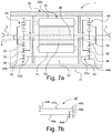
- Fig. 7a schematically shows an axial cross section view of an electrical drive arrangement, where the electrical drive arrangement I illustrated in Figs. 1-5 in a variant is designed according to the electrical drive arrangement I of Fig. 7a.
- Fig. 7b illustrates a top view of a differential device 40 of the electrical drive arrangement I in Fig. 7a .
- the electrical drive arrangement I comprises a pendulum suspension, not shown in Fig. 7a , according to the pendulum suspension in Figs. 1-5a .
- the electrical drive arrangement I is intended to be pendulum suspended.
- the electrical drive arrangement I comprises an electric motor 20 and a housing 30 in which the electric motor 20 is accommodated.
- the electrical drive arrangement I is arranged to propel a motor vehicle.
- the housing 30 has an envelope surface 31 and a substantially annular cross section wherein the horizontal direction of the envelope surface 31 of said housing and hereby said drive shaft 26 are arranged to run substantially transverse to the longitudinal direction of said vehicle.
- the electric motor 20 comprises a rotor 22 and a stator 24, where said rotor 22 is connected to a drive shaft 26 or rotor shaft 26 and is arranged to rotate said drive shaft 26.
- the housing 30 has an envelope surface 31 and a substantially annular cross section wherein the horizontal direction of the envelope surface 31 of said housing and hereby said drive shaft 26 are arranged to run substantially transverse to the longitudinal direction of said vehicle.
- the drive shaft 26 is arranged to run concentrically relative to the rotor 22, wherein the rotor 22 is arranged to surround the drive shaft 26.
- the stator 24 is arranged to surround the rotor 22, wherein the rotor shaft and hence the rotor 22 are arranged concentrically relative to the stator 24.
- the drive shaft 26 is arranged to run substantially horizontally.
- the drive shaft 26 is intended to be connected to and drive ground engaging means such as drive wheels or drive tracks.
- the electrical drive arrangement I is arranged to drive the ground engaging means such as drive wheels or drive tracks for the propulsion of the motor vehicle.
- the drive shaft 26 runs concentrically relative to the imaginary centre axis of the electric motor 20.
- a desired space 36 between the electric motor and said housing is formed.
- Said desired space 36 has a valley-like configuration.
- the housing 30 has a substantially annular cross section with an imaginary centre axis X.
- the housing 30 has a substantially circular cross section.
- the electric motor 20 is eccentrically displaced arranged in the housing 30 such that the drive shaft 26 of the electric motor 20 runs parallel with and spaced from the centre axis X of the housing 30 to form said desired space 36.
- the housing 30 is intended to be arranged substantially horizontally such that the imaginary centre axis X extends substantially horizontally.
- the electric motor 20 is displaced substantially radially upwards in the substantially circular cylindrical housing 30.
- the housing 30 constitutes a middle portion of a supporting structure in the electrical drive arrangement I.
- the displacement of the drive shaft 26/the imaginary centre axis 26 of the electric motor 20 relative to the imaginary centre axis of the housing 30 is 20-100 mm, in a variant about 45 mm.
- Said displacement can be within any suitable range comprising greater ranges than the above mentioned.
- said desired space runs axially in the lower region of the housing 30.
- the centimetres gained under the electric motor 20 because of the eccentric location of the electric motor 20 relative to the drive shaft 26 are utilized for location of differential shaft configuration 42a, 42b of the differential device 40 and the oil sump O. Further, it is facilitated to via the connection unit in a smooth manner take out the cabling from the middle of the housing 30, which is illustrated in among others Figs. 3 and 4 and is explained in more detail below.
- the electrical drive arrangement I comprises an output shaft 12 connected to the drive shaft 26.
- the output shaft 12 is aligned with drive shaft 26.
- the output shaft 12 extends through said drive shaft 26.
- the electrical drive arrangement I comprises differential means arranged in the housing 30.
- Said differential means comprises a first transmission configuration 50 in the form of a first planetary gear configuration 50 and a second transmission configuration 60 in the form of a second planetary gear configuration 60, where the electric motor 20 is arranged between said first and second planetary gear configurations 50, 60.
- the first planetary gear configuration 50 comprises planetary wheel(s) 52, a sun wheel 54, and a ring wheel 56.
- the second planetary gear configuration 60 comprises planetary wheel(s) 62, a sun wheel 64, and a ring wheel 66.
- the first and second planetary gear configurations 50, 60 are drivingly connected to each other via said output shaft 12.
- the output shaft 12 is connected to the sun wheel 54, 64 of the respective planetary gear configuration 50, 60.
- the differential means comprises the differential device 40 engaged with the ring wheel 56 of the first planetary gear configuration 50 and the ring wheel 66 of the second planetary gear configuration 60 for accomplishing differential function of a motor vehicle.
- the differential device 40 comprises a shaft configuration 42a, 42b which is arranged in the housing 30 between the electric motor and housing wall of the housing 30 in the space 36 that is freed by said displacement of the centre axis 26 of the electric motor 20 relative to the centre axis X of the housing 30.
- the shaft configuration comprises a first differential shaft 42a and a second differential shaft 42b which run substantially parallel along each other in the axial longitudinal extension of the housing in the space 36.
- the differential device comprises differential drives 44a, 44b, 46a, 46b, wherein the drive 44a on the first differential shaft 42a is in meshing engagement with the ring wheel 56 and the drive 44b on the first differential shaft 42b is in meshing engagement with the ring wheel 66.
- the differential device 40 is arranged to shift up the output shaft 5 on one side while the other side is shifted down which is accomplished by that the ring wheels 56, 66 are allowed to rotate opposed to each other by means of the drives 46a, 46b.
- the electric motor 20 of the electrical drive arrangement I is axially aligned with the output shaft 5 and the shaft configuration 42 of the differential device 40 is arranged to run along the envelope surface of the electric motor 20 in the space 36, in the housing 30, freed by the displacement of the centre axis of the electric motor 20 relative to the centre axis of the housing 30.
- construction member for the housing 30 is constituted by a pipe having circular cross section which is optimal for load carrying.
- volume uppermost in the housing 30 is utilized, i.e. the electric motor is arranged such that its upper envelope surface runs axially along the inner upper surface of the housing 30, while the shaft configuration of the differential device is arranged under the electric motor 20 in the space 36 which is freed, i.e. the shaft configuration is arranged such that it runs axially in space 36 along the inner bottom surface of the housing 30, wherein a compact construction is obtained, while a circular cylindrical pipe is utilized having the above mentioned advantages.
- the electric motor 20 is located eccentrically in the circular cylindrical housing 30 horizontally arranged in a vehicle, i.e. the rotation centre of the drive shaft 26 is radially displaced relative to the imaginary centre axis X of the circular cylindrical housing 30, wherein thus room is provided to the shaft configuration 42a, 42b of the differential device 40 in the housing 30 in the axially running space 36 below the electric motor 20.
- the volume that becomes available when the electric motor 20 is displaced is utilized as oil sump O and provides as mentioned room for the shaft configuration 42a, 42b of the differential device 40 as well as for a not shown differential break/torque-vectoring.
- the freed space 36 enables gathering of connections for lubricant, coolant, power feeding and sensors, etc. and connecting these to the connection unit of the present invention.
- the electrical drive arrangement I of the present invention is intended primarily for medium heavy and heavy special vehicles.
- the electric motor 20 is horizontally located in the vehicle wherein the envelope 21 of the electric motor 20 and the envelope 31 of housing 30 run in the width direction of the vehicle.
- the electric motor 20 is further eccentrically located relative to the circular cylindrical housing 30 arranged horizontally in the vehicle, whereby also coaxiality is retained between the drive shaft and the output shaft and hence the drive wheel.
- the housing has a substantially circular cylindrical cross section.
- the housing of the electrical drive arrangement I may have any suitable annular cross section.
- the housing has a substantially elliptical cross section.
- the housing has a substantially ovoid cross section.
- the housing has a substantially oblong cross section with parallel sides and semi-circular ends.
- the electrical drive arrangement I has been described where the electric motor is eccentrically located in the housing.
- the electrical drive arrangement I has a housing with a substantially circular cross section having a centre axis, wherein the electric motor is concentrically arranged in the housing such that the drive shaft/the centre axis of the electric motor is aligned with the centre axis of the housing.
- FIG. 1 an electrical drive arrangement I is shown where the pendulum attachment of the pendulum suspension and hereby the connection unit, connected to said pendulum attachment inside the inner bearing part of said slide bearing, are arranged such that imaginary pivot axis of the pendulum suspension runs in the horizontal centre plane of the housing transverse to the axial direction of the housing. This results in a stable and balanced pendulum suspension of the electrical drive arrangement I.
- an electrical drive arrangement I where the pendulum attachment of the pendulum suspension and hereby the connection unit, connected to said pendulum attachment inside the inner bearing part of said slide bearing, are arranged such that imaginary pivot axis of the pendulum suspension runs in a lower region between the horizontal centre plane of the housing and the lowermost portion of the envelope surface of the housing transverse to the axial direction of the housing.
- imaginary pivot axis of the pendulum suspension runs in a lower region between the horizontal centre plane of the housing and the lowermost portion of the envelope surface of the housing transverse to the axial direction of the housing.
- Said inner bearing part of the front and rear slide bearings may be fastened to the envelope surface of the housing in any suitable manner by means of any suitable fastening members such as bolt connections, rivet connections or similar.
- said inner bearing part of the front and rear slide bearings are fastened directly at the envelope surface 31 of the housing 30.
- said inner bearing part of the front and rear slide bearings are fastened about an annular portion of the housing 30 projecting substantially perpendicular and horizontal from the envelope surface 31 of the housing 30.
- said connection unit is connected internally at such a hollow annular projecting portion.
- said bearing configuration comprises only one of the front and rear slide bearings, in a variant only the front slide bearing.
- the pendulum suspension comprises only one slide bearing where, in a variant, the slide bearing constitutes a front slide bearing.
Landscapes
- Engineering & Computer Science (AREA)
- Mechanical Engineering (AREA)
- Power Engineering (AREA)
- Chemical & Material Sciences (AREA)
- Combustion & Propulsion (AREA)
- Transportation (AREA)
- Electric Propulsion And Braking For Vehicles (AREA)
- Arrangement Or Mounting Of Propulsion Units For Vehicles (AREA)
- Connection Of Motors, Electrical Generators, Mechanical Devices, And The Like (AREA)
Description
- The invention relates to an electrical drive arrangement according to the preamble of
claim 1. The invention also relates to a motor vehicle. - The automotive industry is undergoing a period of change where the vehicles are electrified to a greater extension, where a trend is hybridization of different degree. There are high demands for compactness and high power and torque output.
- Further, for work vehicles and military vehicles the manoeuvrability of the vehicle is important.
-
WO2012066035 discloses an electric shaft of a motor vehicle comprising an electric motor for propulsion of the vehicle arranged coaxially on said shaft and hence transverse to the longitudinal extension of the vehicle. The electric shaft has transmission configurations on each side of the electric motor. Such an electrical shaft enables a compact and volume-efficient construction. -
DE 10 2009 002 440 A1 discloses an electrical drive arrangement according to the preamble ofclaim 1. - An object of the present invention is to obtain an electrical drive arrangement for driving a motor vehicle with a compact and volume-efficient design that enables improved manoeuvrability of the motor vehicle.
- These and other objects, which will become apparent from the following description, are obtained by means of an electrical drive arrangement as defined in
claim 1 as well as a motor vehicle as defined in claim 15. Preferred embodiments of the electrical drive arrangement are defined in appended dependent claims 2-14. According to the invention, the objects are obtained by an electrical drive arrangement for driving a motor vehicle comprising an electric motor, a drive shaft driven by means of the electric motor, a housing in which the electric motor is accommodated, which housing has an envelope surface and a substantially annular cross section wherein the horizontal direction of the envelope surface of said housing and hereby said drive shaft are arranged to run substantially transverse to the longitudinal direction of said vehicle, comprising a pendulum suspension for suspension of the electrical drive arrangement, where the pendulum suspension comprises a fastening configuration fixedly connected to the vehicle and at least one pendulum attachment fixedly connected to the envelope surface of the housing and pivotally journaled relative to said fastening configuration by means of a bearing configuration. This enables improved mobility of the vehicle, by a compact, volume-efficient design of the electrical drive arrangement. - In an embodiment of the electrical drive arrangement, the electric motor has a stator and a rotor arranged to rotate the drive shaft.
- In an embodiment of the electrical drive arrangement, said drive shaft is arranged for driving two output shafts for driving ground engaging means, preferably via suitable transmission configurations and wherein said output shafts are arranged to run substantially transverse to the longitudinal direction of said vehicle.
- In an embodiment of the electrical drive arrangement, said fastening configuration is arranged for suspension of a front and a rear pendulum attachment. This results in a stable suspension of the electrical drive shaft arrangement.
- In an embodiment of the electrical drive arrangement, said bearing configuration comprises slide bearing. The advantage of using slide bearing is that it is space saving for the pendulum suspended drive shaft.
- In an embodiment of the electrical drive arrangement, said slide bearing comprises an outer bearing part fixedly connected to said fastening configuration and an inner bearing part fixedly connected to said pendulum attachment and internally and slidable relative to said outer bearing part. This provides a compact and efficient pendulum suspension for the electrical drive arrangement.
- In an embodiment of the electrical drive arrangement, said pendulum attachment is connected to a connection unit attached at the envelope surface of said housing for medium supply of the electric motor, wherein said medium supply is arranged to take place via an opening in the envelope surface of said housing. Thus, by arranging the connection unit adjacent to the pendulum attachment, the relative motion of the connection unit affected becomes relative to the vehicle body during pendulum of the electrical drive arrangement and where connected cables and lines relatively small which makes it easier to clutch cabling and lines to the vehicle body such as vehicle frame/chassis. Hence, this enables minimizing of the movement of the connection unit during rotation of the pendulum attachment relatively the fastening configuration wherein for instance cabling clutched to the connection unit and attached to fixed part of the vehicle is not significantly affected/pivoted during said rotation. Further, this enables, by medium supplying the electric motor via the connection unit in the form of energy supply from power electronics, providing of an axially compact electrical drive arrangement where the electrical drive arrangement comprises transmission configuration arranged on respective side of the electric motor since no cabling needs to be connected/disconnected on any of the sides of the electric motor to free up space at the ends for compact connection of the transmission configuration. The transmission configuration may be constituted by planetary gear/reduction gear. Further, by medium supplying the electric motor via the connection unit in the form of coolant and lubricant and, where proper, transmission configurations in the form of planetary gears/reduction gears, simple and efficient cooling and lubrication of the electrical drive arrangement, and hence efficient operation, is enabled. By being able to connect both the cabling for electric energy, lines for lubricant and coolant, and cabling for signal connection at the same place, the laying of the cabling/lines, and clutching of the same, is facilitated.
- In an embodiment of the electrical drive arrangement, said connection unit is connected to said pendulum attachment inside the inner bearing part of said slide bearing. This minimizes the movement of the connection unit during rotation of the pendulum attachment relatively the fastening configuration wherein for instance cabling connected at the connection unit and clutched to fixed part of the vehicle is not affected/pivoted significantly during said rotation.
- In an embodiment of the electrical drive arrangement, said pendulum attachment is arranged between uppermost and lowermost portions of the envelope surface of said housing. Hereby, the ground clearance of the vehicle or the height of the vehicle is not affected by the pendulum attachment, wherein such an embodiment of the electrical drive arrangement is well suited for, for instance, mining vehicles that move in confined spaces.
- In an embodiment of the electrical drive arrangement, said pendulum attachment axially is arranged substantially adjacent to a central portion of the envelope surface of said housing. This results in a stable pendulum suspension. By having the connection unit connected to said pendulum attachment thus arranged inside the inner bearing part of said slide bearing, the replacement of conventional mechanical drive train with electrical drive arrangement is facilitated, according the present invention, where space centrally of the vehicle is freed, where a propeller shaft centrally arranged of the conventional drive train has been taking up space, wherein cabling can be led centrally in the longitudinal extension for connection to the generator.
- In an embodiment of the electrical drive arrangement, the pendulum attachment circumferentially of the envelope surface of the housing is located adjacent to a horizontal centre plane of the envelope surface of the housing. This results in a stable pendulum suspension.
- In an embodiment of the electrical drive arrangement, said medium supply comprises energy supply by means of power electronics and/or coolant and lubricant supply.
- In an embodiment of the electrical drive arrangement, an oil sump is arranged at the bottom of the housing in a desired space formed between the electric motor and said housing under a lowermost portion of the envelope surface of the electric motor, for said coolant and lubricant supply. This enables for efficient lubrication of gears/cogwheels and uptaking of oil coolant for cooling the electric motor.
- In an embodiment of the electrical drive arrangement, the electric motor is eccentrically arranged in the housing such that the centre of rotation of the drive shaft of the electric motor runs substantially parallel to and spaced from an imaginary centre axis of the housing to form said desired space. This enables a compact, volume-efficient and stable arrangement while space is freed for, for instance, oil sump and/or differential/differential shaft in the housing. Further, gathering of connections for medium supply comprising coolant and lubricant to the oil sump via the connection unit, as well as outtake of cabling via the connection unit out of the housing, is facilitated.
- In an embodiment, the electrical drive arrangement further comprises a differential device having a shaft configuration arranged in the housing in the desired space between the electric motor and the housing. This results in a compact solution with differential device for differential function, which differential device is connected to planetary gears, wherein effective operation is enabled.
- The present invention will be better understood by reference to the following detailed description read together with the accompanying drawings, wherein equal reference numerals refer to the same parts throughout the several views, and in which:
-
Fig. 1 schematically illustrates a motor vehicle with an electrical drive arrangement I according to an embodiment of the present invention; -
Fig. 2 schematically illustrates a plan view of a motor vehicle with the electrical drive arrangement I ofFig. 1 according to an embodiment of the present invention; -
Fig. 3 schematically illustrates a front view of an electrical drive arrangement I according to an embodiment of the present invention; -
Fig. 4 schematically shows a radial cross sectional view of the electrical drive arrangement I ofFig. 3 ; -
Fig. 5 schematically illustrates a plan view of the electrical drive arrangement I ofFig. 3 ; -
Fig. 6a schematically illustrates a system for supply via a supply unit of a drive unit of the electrical drive arrangement I according to an embodiment of the present invention; andFig. 6b schematically illustrates a part of the system according to an alternative variant; -
Fig. 7a schematically shows an axial cross sectional view of the electrical drive arrangement I ofFig. 3 ; andFig. 7b schematically shows a top view of a differential device of the electrical drive arrangement I ofFig. 7a . -
Fig. 1 schematically illustrates amotor vehicle 1 according to an embodiment of the present invention. The exemplifiedvehicle 1 is constituted by a heavy vehicle in the form of a work vehicle such as a mining vehicle. In an alternative variant, the vehicle is constituted by a military vehicle. In a variant, the motor vehicle is constituted by an articulated vehicle. Themotor vehicle 1 comprises an electrical drive arrangement I according to any of the embodiments of the present invention. Themotor vehicle 1 is intended to be propelled by means of the drive arrangement. Themotor vehicle 1 comprises avehicle body 2 comprising a vehicle frame. - The electrical drive arrangement I is arranged to drive
output shafts 5. Hub means 6a, 6b are arranged at the end of therespective output shaft 5. In a variant, hub means 6a, 6b are constituted byhub reductions Ground engaging means respective hub reduction vehicle 1. In a variant, theground engaging means ground engaging means - Said
output shafts 5 are arranged to run substantially transverse to the longitudinal direction of thevehicle 1 intended to be driven by means of the electrical drive arrangement I. - As shown in
Fig. 4 andFig. 7a , the electrical drive arrangement I comprises ahousing 30 and anelectric motor 20 accommodated in thehousing 30 arranged to drive adrive shaft 26. In an embodiment, saidoutput shafts 5 are arranged substantially coaxially with saidelectric motor 20, i.e. aligned with thedrive shaft 26 of the electric motor. This results in efficient operation of thevehicle 1. In an alternative embodiment, saiddrive shaft member 5 arranged radially displaced relative to saidelectric motor 20, where, in a variant, saidoutput shafts 5 are radially displaced relative to theelectric motor 20 such that theground engaging means - Further, the electrical drive arrangement I comprises a
pendulum suspension 70 for suspending the electrical drive arrangement I. - The
pendulum suspension 70 comprises a fastening configuration fixedly connected to thevehicle 1 and apendulum attachment 76 fixedly connected to anenvelope surface 31 of thehousing 30 and pivotally journaled relative to saidfastening configuration 72 by means of a bearingconfiguration 82. Hence, the electrical drive arrangement I is rotatable relative to thebody 2 of the vehicle. - In a variant, the electrical drive arrangement I is intended to drive heavy vehicles, such as work vehicles.
-
Fig. 2 schematically illustrates a plan view of a motor vehicle with the electrical drive arrangement I ofFig. 1 according to an embodiment of the present invention. - The electrical drive shaft arrangement, that here constitutes the rear driving shaft, is pendulum suspended while the front shaft is rigidly fastened in the frame of the vehicle. This improves the manoeuvrability of the vehicle.
-
Fig. 3 schematically illustrates a front view of an electrical drive arrangement I according to an embodiment of the present invention, for instance an electrical drive arrangement I according toFigs. 1 and 2 ,Fig. 4 a radial cross sectional view of the electrical drive arrangement I of theFig. 3 andFig. 5 a plan view of the electrical drive arrangement I of theFig. 3 . - The electrical drive arrangement I for driving a
motor vehicle 1 comprises anelectric motor 20 as well as adrive shaft 26 driven by means of the electric motor. Theelectric motor 20 has a substantially circular cylindrical shape. Theelectric motor 20 has anenvelope surface 21. The electrical drive arrangement I further comprises ahousing 30 in which the electric motor is accommodated. The housing has anenvelope surface 31 and a substantially annular cross section. The horizontal direction of theenvelope surface 31 of saidhousing 30 and hereby saiddrive shaft 26 are arranged to run substantially transverse to the longitudinal direction of said vehicle as shown inFig. 1 and Fig. 2 . Saidhousing 30 is axially, i.e. transverse to the longitudinal direction of the vehicle, arranged substantially centrally of the vehicle and saidoutput shafts 5. - The
electric motor 20 has astator 22 and arotor 24 arranged to rotate thedrive shaft 26. Said drive shaft is arranged for driving said twooutput shafts 5 for driving the ground engaging means, preferably viasuitable transmission configurations output shafts 5 are arranged to run substantially transversely to the longitudinal direction of said vehicle. - According to the embodiment illustrated in
Fig. 3 , the electrical drive arrangement I comprisestransmission configurations electric motor 20. - The electrical drive arrangement I further comprises, as shown in
Figs. 3 and 4 , adifferential device 40 superposed arranged and connected to saidtransmission configurations - The electrical drive arrangement I further comprises a
pendulum suspension 70 for suspending the electrical drive arrangement I. - The
pendulum suspension 70 comprises afastening configuration 72 fixedly connected to the vehicle and apendulum attachment configuration 80 relative to saidfastening configuration 72, comprising afront pendulum attachment 74 and arear pendulum attachment 76. Hence, the electrical drive arrangement I is rotatable relative to thebody 2 of the vehicle. - Said
fastening configuration 72 is arranged for suspension of said front andrear pendulum attachment - Said bearing
configuration slide bearing outer bearing part fastening configuration 72 and aninner bearing part pendulum attachment outer bearing part 80a, 80b. Said outer andinner bearing parts pendulum suspension 70. - One of said front and
rear pendulum attachments front pendulum attachment 74, is connected to aconnection unit 100 attached at theenvelope surface 31 of saidhousing 30 for the medium supply of theelectric motor 20 andtransmission configuration envelope surface 31 of saidhousing 30. - Said
connection unit 100 is connected to saidpendulum attachment 70 inside theinner bearing part 80b of saidslide bearing 80. Said medium supply comprises energy supply by means of power electronics as well as coolant and lubricant supply. Saidconnection unit 100 comprises connection interface(s) 100a for connecting cabling for said power electronics and cabling for said coolant and lubricant supply. An embodiment of said connection interface(s) is described in more detail with reference toFigs. 6a and 6b . - The
envelope surface 31 of saidhousing 30 has anuppermost portion 30a and a lowermost portion 30b.Said pendulum attachment 74 is arranged between the uppermost andlowermost portions envelope surface 31 of thehousing 30. Saidpendulum attachment 74 is axially arranged substantially adjacent to a central portion of theenvelope surface 31 of saidhousing 30. Said pendulum attachment is circumferentially of theenvelope surface 31 of thehousing 30 located adjacent to a horizontal centre plane of theenvelope surface 31 of thehousing 30. - Hereby, the
front pendulum attachment 74 is arranged on the front side of theenvelope surface 31 of saidhousing 30 between the uppermost and lowermost portions of theenvelope surface 31 of saidhousing 30, axially arranged substantially adjacent to a central portion of theenvelope surface 31 of saidhousing 30, and circumferentially of theenvelope surface 31 of thehousing 30 located adjacent to a horizontal centre plane of theenvelope surface 31 of thehousing 30. - Correspondingly, the
rear pendulum attachment 76 is arranged on the rear side of theenvelope surface 31 of saidhousing 30 between the uppermost andlowermost portions envelope surface 31 of saidhousing 30, axially arranged substantially adjacent to a central portion of theenvelope surface 31 of saidhousing 30, and circumferentially of theenvelope surface 31 of thehousing 30, located adjacent to a horizontal centre plane of theenvelope surface 31 of thehousing 30. Hence, therear pendulum attachment 76 is arranged at theenvelope surface 31 of thehousing 30 substantially opposed to and aligned with thefront pendulum attachment 74 such that an imaginary axis Y between the front pendulum attachment and the rear pendulum attachment, i.e. the axis Y about which the pendulum suspended electrical drive arrangement I is pivotable relative to the frame/chassis of the vehicle, runs substantially in the longitudinal extension. Hereby, saidconnection unit 100 is arranged on the front side of theenvelope surface 31 of saidhousing 30 between the uppermost andlowermost portions envelope surface 31 of saidhousing 30, axially arranged substantially adjacent to a central portion of theenvelope surface 31 of saidhousing 30, and circumferentially of theenvelope surface 31 of thehousing 30 located adjacent to a horizontal centre plane of theenvelope surface 31 of thehousing 30. - By arranging the
connection unit 100 between the uppermost andlowermost portions envelope surface 31, the ground clearance of the vehicle is not affected by theconnection unit 100 nor the height of the vehicle. Further, in a variant, theconnection unit 100 is arranged adjacent theenvelope surface 31 of thehousing 30 such that splashes, in the form of, for instance, stones, gravel, mud and/or water ripped from ground engaging means connected to other drive shafts such as wheels, are not ending up on theconnection unit 100. - Said bearing
configuration outer bearing part 80a fixedly connected to saidfastening configuration 72 and aninner bearing part 80b fixedly connected to saidfront pendulum attachment 74 and slidable internally and relative to saidouter bearing part 80a. - Said bearing
configuration outer bearing part 82a fixedly connected to saidfastening configuration 72 and aninner bearing part 82b fixedly connected to saidrear pendulum attachment 76 and slidable internally and relative to saidouter bearing part 82a. - The
fastening configuration 72 comprises afront fastening portion 72a and arear fastening portion 72b. - The
front fastening portion 72a is arranged in front of thehousing 30 and therear fastening portion 72b is arranged behind thehousing 30. Thefront fastening portion 72a is at an end region fixedly connected to thebody 2/chassis 2/frame 2 of the vehicle and at an opposed end region fixedly connected to theouter bearing part 80a of thefront slide bearing 80. - The
rear fastening portion 72b is at an end region fixedly connected to thebody 2/chassis 2/frame 2 of the vehicle and at an opposed end region fixedly connected to theouter bearing part 82a of therear slide bearing 82. - As shown as an example in
Fig. 3 , said medium supply comprises electrical energy supply as well as coolant and lubricant supply. Theconnection unit 100 is configured for connection of cabling 105 for electric energy supply as well aslines connection unit 100 that is arranged adjacent to the envelope surface of the housing inside the inner portion of the bearing configuration. - The
connection unit 100 comprises connection interface(s) for cabling for said electrical energy supply. - The
connection unit 100 comprises connection interface(s) for connection of line configuration for pumping, by means of a not shown pumping unit, coolant and lubricant for coolant and lubricant supply of thetransmission configuration uptake line 101 for taking up oil from the oil sump for pumping via heat exchangers returning via theconnection unit 100 for supplying theelectric motor 20 and thetransmission configurations - The
connection unit 100 comprises connection interface(s) for said coolant andlubrication lines electric motor 20 and thetransmission configurations transmission configurations envelope 21 of theelectric motor 20 for cooling theelectric motor 20 by means of the coolant, where, in an embodiment, the lubricant and the coolant are constituted by oil from the same source in the form of the oil sump O. - An axially running
space 36 under the envelope surface of theelectric motor 20 is utilized as oil sump O. In this embodiment, the volume becomes available by that theelectric motor 20 is eccentrically arranged relative to thehousing 30. Thespace 36 provides room for theshaft configuration Figs. 7a and 7b , and consequently to a differential brake/torque-vectoring not shown. -
Fig. 6a schematically illustrates a system S for supply of supply means via a connection unit of the electrical drive arrangement I according to an embodiment of the present invention. - The system comprises said
connection unit 100. The system further comprises a pump unit P arranged to, in a line configuration, pump coolant and lubricant, in a variant oil, from a space at the bottom of the housing of the electrical drive arrangement I, according to the present invention, by anuptake line 101 via saidconnection unit 100. The system S further comprises a filter member F arranged downstream of the pump unit P and configured to filter coolant and lubricant pumped from the space. The system S further comprises a heat exchanger HX arranged downstream of the pump unit P and configured to cool heated coolant and lubricant. - The line configuration comprises an
inlet line 103, arranged downstream of the heat exchanger HX, which is connected to theconnection unit 100 for supply of coolant and lubricant to the transmission configuration and the electric motor. Saidinlet line 103 is connected to theconnection unit 100 branched into a set ofsupply lines - In an embodiment, the
connection unit 100 comprises not shown overflow valves that are arranged to open based on a predetermined pressure. Hereby, the priority of supply is arranged to take place such that the transmission configurations, in a variant planetary gears arranged on either side of the electric motor, as well as the differential configuration, first are provided with coolant and lubricant via afirst supply line 103a of the set ofsupply lines second supply line 103b, whereby then athird supply line 103c is activated for providing the electric motor rotor with coolant and lubricant, and then the envelope of the electric motor is provided with coolant and lubricant, as well as also bearings. This for instance if the performance of the pump unit P is impaired, wherein the accessibility of the vehicle is ensured in that the risk of failed transmission configurations is avoided. - Hence, in a variant, cooled oil is intended to by high pressure be led in the
inlet line 103 into theconnection unit 100, branched into theset supply lines connection unit 100 and via the pump unit P through the filter F and via the heat exchanger HX for cooling the oil and then returning through the inlet line for supplying the transmission configuration and the electric motor. - The system S further comprises power electronics E arranged to electrically energy supply the electric motor. Said power electronics E is connected to the electric motor via the
cabling 105 in the form of three-phase line, which cabling is connected to the electric motor via theconnection unit 100. - In an embodiment, the system also comprises an electronic control unit ECU. The electronic control unit ECU is arranged to receive signals from a
signal line configuration 107 via theconnection unit 100. The electronic control unit is arranged to receive signals from not shown sensor means arranged in connection with electrical drive unit of the electrical drive arrangement I according to the present invention, where said sensor means may comprise flow sensor(s) for determining the flow rate of the coolant and lubricant, level sensor(s) for determining coolant and lubricant level of the oil sump, pressure sensor(s) for determining the pressure of the coolant and lubricant, temperature sensor(s) for determining the temperature of the electric motor, temperature sensor(s) for determining the temperature of the coolant and a lubricant such as oil, position sensor(s) such as a resolver/encoder for determining the position of the rotor of the electric motor, rotation sensor(s) for determining the rotation speed of the rotor, particle measurement sensor(s) for determining the amount of particles of the coolant and lubricant such as oil to determine if the amount of particles of the coolant and lubricant has become high which may indicate wear of for example cogwheels, wherein the electronic control unit ECU is arranged to receive signals from said sensor means representing the flow data, the level data, the pressure data and the temperature data. - The electronic control unit ECU is further connected to said power electronics E. The electronic control unit ECU is arranged to transmit signal to the power electronics representing controlling of the electric motor based on information from the sensor means concerning for instance the rotor position as well as the temperature of the electric motor.
- In
Fig. 6a , the branching of thesupply line 103 takes place in a branching configuration Y1 in theconnection unit 100. The branching of theinlet line 103 may take place by any suitable branching configuration.Fig. 6b schematically shows a branching configuration Y2 where a sub branching of theinlet line 103 takes place in theconnection unit 100, here to two lines, wherein these lines then are branched inside/downstream of theconnection unit 100 in respective twosupply lines 103a', 103b', and 103c', 103d'. -
Fig. 7a schematically shows an axial cross section view of an electrical drive arrangement, where the electrical drive arrangement I illustrated inFigs. 1-5 in a variant is designed according to the electrical drive arrangement I ofFig. 7a. Fig. 7b illustrates a top view of adifferential device 40 of the electrical drive arrangement I inFig. 7a . - The electrical drive arrangement I comprises a pendulum suspension, not shown in
Fig. 7a , according to the pendulum suspension inFigs. 1-5a . Hence, the electrical drive arrangement I is intended to be pendulum suspended. Hence, the electrical drive arrangement I comprises anelectric motor 20 and ahousing 30 in which theelectric motor 20 is accommodated. The electrical drive arrangement I is arranged to propel a motor vehicle. Thehousing 30 has anenvelope surface 31 and a substantially annular cross section wherein the horizontal direction of theenvelope surface 31 of said housing and hereby saiddrive shaft 26 are arranged to run substantially transverse to the longitudinal direction of said vehicle. - The
electric motor 20 comprises arotor 22 and astator 24, where saidrotor 22 is connected to adrive shaft 26 orrotor shaft 26 and is arranged to rotate saiddrive shaft 26. Thehousing 30 has anenvelope surface 31 and a substantially annular cross section wherein the horizontal direction of theenvelope surface 31 of said housing and hereby saiddrive shaft 26 are arranged to run substantially transverse to the longitudinal direction of said vehicle. - The
drive shaft 26 is arranged to run concentrically relative to therotor 22, wherein therotor 22 is arranged to surround thedrive shaft 26. Thestator 24 is arranged to surround therotor 22, wherein the rotor shaft and hence therotor 22 are arranged concentrically relative to thestator 24. Thedrive shaft 26 is arranged to run substantially horizontally. Thedrive shaft 26 is intended to be connected to and drive ground engaging means such as drive wheels or drive tracks. Hence, the electrical drive arrangement I is arranged to drive the ground engaging means such as drive wheels or drive tracks for the propulsion of the motor vehicle. - Hence, in this embodiment, the
drive shaft 26 runs concentrically relative to the imaginary centre axis of theelectric motor 20. Hereby, a desiredspace 36 between the electric motor and said housing is formed. Said desiredspace 36 has a valley-like configuration. - The
housing 30 has a substantially annular cross section with an imaginary centre axis X. In this embodiment, thehousing 30 has a substantially circular cross section. Theelectric motor 20 is eccentrically displaced arranged in thehousing 30 such that thedrive shaft 26 of theelectric motor 20 runs parallel with and spaced from the centre axis X of thehousing 30 to form said desiredspace 36. Hence, thehousing 30 is intended to be arranged substantially horizontally such that the imaginary centre axis X extends substantially horizontally. - In this embodiment, the
electric motor 20 is displaced substantially radially upwards in the substantially circularcylindrical housing 30. Thehousing 30 constitutes a middle portion of a supporting structure in the electrical drive arrangement I. In a variant, the displacement of thedrive shaft 26/theimaginary centre axis 26 of theelectric motor 20 relative to the imaginary centre axis of thehousing 30 is 20-100 mm, in a variant about 45 mm. Said displacement can be within any suitable range comprising greater ranges than the above mentioned. Hence, said desired space runs axially in the lower region of thehousing 30. - The centimetres gained under the
electric motor 20 because of the eccentric location of theelectric motor 20 relative to thedrive shaft 26 are utilized for location ofdifferential shaft configuration differential device 40 and the oil sump O. Further, it is facilitated to via the connection unit in a smooth manner take out the cabling from the middle of thehousing 30, which is illustrated in among othersFigs. 3 and 4 and is explained in more detail below. - The electrical drive arrangement I comprises an output shaft 12 connected to the
drive shaft 26. In this embodiment, the output shaft 12 is aligned withdrive shaft 26. In this embodiment, the output shaft 12 extends through saiddrive shaft 26. - In this embodiment, the electrical drive arrangement I comprises differential means arranged in the
housing 30. Said differential means comprises afirst transmission configuration 50 in the form of a firstplanetary gear configuration 50 and asecond transmission configuration 60 in the form of a secondplanetary gear configuration 60, where theelectric motor 20 is arranged between said first and secondplanetary gear configurations - The first
planetary gear configuration 50 comprises planetary wheel(s) 52, asun wheel 54, and aring wheel 56. The secondplanetary gear configuration 60 comprises planetary wheel(s) 62, asun wheel 64, and aring wheel 66. - The first and second
planetary gear configurations sun wheel planetary gear configuration - The differential means comprises the
differential device 40 engaged with thering wheel 56 of the firstplanetary gear configuration 50 and thering wheel 66 of the secondplanetary gear configuration 60 for accomplishing differential function of a motor vehicle. - The
differential device 40 comprises ashaft configuration housing 30 between the electric motor and housing wall of thehousing 30 in thespace 36 that is freed by said displacement of thecentre axis 26 of theelectric motor 20 relative to the centre axis X of thehousing 30. - As shown in
Fig. 7b , the shaft configuration comprises a firstdifferential shaft 42a and a seconddifferential shaft 42b which run substantially parallel along each other in the axial longitudinal extension of the housing in thespace 36. The differential device comprisesdifferential drives drive 44a on the firstdifferential shaft 42a is in meshing engagement with thering wheel 56 and thedrive 44b on the firstdifferential shaft 42b is in meshing engagement with thering wheel 66. - The
differential device 40 is arranged to shift up theoutput shaft 5 on one side while the other side is shifted down which is accomplished by that thering wheels drives - The
electric motor 20 of the electrical drive arrangement I is axially aligned with theoutput shaft 5 and the shaft configuration 42 of thedifferential device 40 is arranged to run along the envelope surface of theelectric motor 20 in thespace 36, in thehousing 30, freed by the displacement of the centre axis of theelectric motor 20 relative to the centre axis of thehousing 30. - By using a
cylindrical housing 30 having a circular cross section a flexurallyrigid housing 30 is obtained which is easy and cheap to manufacture. In an embodiment, construction member for thehousing 30 is constituted by a pipe having circular cross section which is optimal for load carrying. By arranging theelectric motor 20 eccentrically in a similar horizontally arrangedhousing 30, volume uppermost in thehousing 30 is utilized, i.e. the electric motor is arranged such that its upper envelope surface runs axially along the inner upper surface of thehousing 30, while the shaft configuration of the differential device is arranged under theelectric motor 20 in thespace 36 which is freed, i.e. the shaft configuration is arranged such that it runs axially inspace 36 along the inner bottom surface of thehousing 30, wherein a compact construction is obtained, while a circular cylindrical pipe is utilized having the above mentioned advantages. - Hence, in this embodiment, the
electric motor 20 is located eccentrically in the circularcylindrical housing 30 horizontally arranged in a vehicle, i.e. the rotation centre of thedrive shaft 26 is radially displaced relative to the imaginary centre axis X of the circularcylindrical housing 30, wherein thus room is provided to theshaft configuration differential device 40 in thehousing 30 in theaxially running space 36 below theelectric motor 20. The volume that becomes available when theelectric motor 20 is displaced is utilized as oil sump O and provides as mentioned room for theshaft configuration differential device 40 as well as for a not shown differential break/torque-vectoring. Further, the freedspace 36 enables gathering of connections for lubricant, coolant, power feeding and sensors, etc. and connecting these to the connection unit of the present invention. - The fact that the output shaft extends through said drive shaft provides a motor in the shaft solution with the
output shaft 5 via theplanetary gear configuration electric motor 20. A motor in the shaft solution requires no propeller shafts but all power transmission takes place via cable. - The electrical drive arrangement I of the present invention is intended primarily for medium heavy and heavy special vehicles. Hereby, the
electric motor 20 is horizontally located in the vehicle wherein theenvelope 21 of theelectric motor 20 and theenvelope 31 ofhousing 30 run in the width direction of the vehicle. Theelectric motor 20 is further eccentrically located relative to the circularcylindrical housing 30 arranged horizontally in the vehicle, whereby also coaxiality is retained between the drive shaft and the output shaft and hence the drive wheel. - Above, embodiments of the electrical drive arrangement I have been shown and described where the housing has a substantially circular cylindrical cross section. The housing of the electrical drive arrangement I may have any suitable annular cross section. In an alternative embodiment, the housing has a substantially elliptical cross section. In an alternative embodiment, the housing has a substantially ovoid cross section. In an alternative embodiment, the housing has a substantially oblong cross section with parallel sides and semi-circular ends.
- Above, an electrical drive arrangement I has been described where the electric motor is eccentrically located in the housing. In an alternative embodiment, the electrical drive arrangement I has a housing with a substantially circular cross section having a centre axis, wherein the electric motor is concentrically arranged in the housing such that the drive shaft/the centre axis of the electric motor is aligned with the centre axis of the housing.
- In
Fig. 1 , an electrical drive arrangement I is shown where the pendulum attachment of the pendulum suspension and hereby the connection unit, connected to said pendulum attachment inside the inner bearing part of said slide bearing, are arranged such that imaginary pivot axis of the pendulum suspension runs in the horizontal centre plane of the housing transverse to the axial direction of the housing. This results in a stable and balanced pendulum suspension of the electrical drive arrangement I. - In
Figs. 3 and 4 , an electrical drive arrangement I is shown where the pendulum attachment of the pendulum suspension and hereby the connection unit, connected to said pendulum attachment inside the inner bearing part of said slide bearing, are arranged such that imaginary pivot axis of the pendulum suspension runs in a lower region between the horizontal centre plane of the housing and the lowermost portion of the envelope surface of the housing transverse to the axial direction of the housing. Hereby, leading out cabling from the electric motor and cooling and lubrication lines from the housing is facilitated. - Said inner bearing part of the front and rear slide bearings may be fastened to the envelope surface of the housing in any suitable manner by means of any suitable fastening members such as bolt connections, rivet connections or similar. In a variant, said inner bearing part of the front and rear slide bearings are fastened directly at the
envelope surface 31 of thehousing 30. In a variant, said inner bearing part of the front and rear slide bearings are fastened about an annular portion of thehousing 30 projecting substantially perpendicular and horizontal from theenvelope surface 31 of thehousing 30. In a variant, said connection unit is connected internally at such a hollow annular projecting portion. - In a variant, said bearing configuration comprises only one of the front and rear slide bearings, in a variant only the front slide bearing. Hence, in a variant not shown, the pendulum suspension comprises only one slide bearing where, in a variant, the slide bearing constitutes a front slide bearing.
- The above description of the preferred embodiments of the present invention has been provided for illustrative and descriptive purposes. It is not intended to be exhaustive or to limit the invention to the variants described. Obviously, many modifications and variations may be apparent to the skilled person. The embodiments were chosen and described to best explain the principles of the invention and its practical applications, thereby enabling a skilled person to understand the invention for various embodiments and with the various modifications suitable for the intended use.
Claims (15)
- An electrical drive arrangement (I) for driving a motor vehicle (1) comprising an electric motor (20), a drive shaft (26) driven by means of the electric motor (20), a housing (30) in which the electric motor (20) is accommodated, which housing (30) has an envelope surface (31) and a substantially annular cross section wherein the horizontal direction of the envelope surface (31) of said housing and hereby said drive shaft (26) are arranged to run substantially transverse to the longitudinal direction of said vehicle (1), further comprising a pendulum suspension (70) for suspension of the electrical drive arrangement (I), where the pendulum suspension (70) comprises a fastening configuration (72) fixedly connected to the vehicle and at least one pendulum attachment (74, 76) fixedly connected to the envelope surface (31) of the housing and pivotally journaled relative to said fastening configuration (72) by means of a bearing configuration (80, 82), characterized in that said pendulum attachment (74, 76) is connected to a connection unit (100), attached at the envelope surface (31) of said housing (30), for medium supply of the electric motor (20), wherein said medium supply is intended to take place via an opening in the envelope surface (31) of said housing.
- The electrical drive arrangement (I) of claim 1, wherein the electric motor (20) has a stator (24) and a rotor (22) arranged to rotate the drive shaft (26).
- The electrical drive arrangement (I) of claim 1 or 2, wherein said drive shaft (26) is arranged for driving two output shafts (5) for driving ground engaging means (7a, 7b), preferably via suitable transmission configurations (50, 60) and wherein said output shafts (5) are arranged to run substantially transverse to the longitudinal direction of said vehicle (1).
- The electric drive arrangement of any of the claims 1-3, wherein said fastening configuration (72) is arranged for suspension of a front and a rear pendulum attachment (74, 76).
- The electrical drive arrangement (I) of any of the claims 1-4, wherein said bearing configuration (80, 82) comprises slide bearing (80, 82).
- The electrical drive arrangement (I) of claim 5, wherein said slide bearing (80, 82) comprises an outer bearing part (80a, 82a) fixedly connected to said fastening configuration (72) and an inner bearing part (80b, 82b) fixedly connected to said pendulum attachment (74, 76) and internally and slidable relative to said outer bearing part (80a, 82a).
- The electrical drive arrangement (I) of claim 6, wherein said connection unit (100) is connected to said pendulum attachment (74) inside the inner bearing part (80b) of said slide bearing (80).
- The electrical drive arrangement (I) of any of the claims 1-7, wherein said pendulum attachment (74, 76) is arranged between uppermost and lowermost portions (30a, 30b) of the envelope surface (31) of said housing (30).
- The electrical drive arrangement (I) of any of the claims 1-8, wherein said pendulum attachment (74, 76) axially is arranged substantially adjacent to a central portion of the envelope surface (31) of said housing (30).
- The electrical drive arrangement (I) of any of the claims 1-9, wherein the pendulum attachment (74, 76) circumferentially of the envelope surface (31) of the housing (30) is located adjacent to a horizontal centre plane of the envelope surface (31) of the housing (30).
- The electrical drive arrangement (I) of any of the claims 1-10, wherein said medium supply comprises energy supply by means of power electronics and/or coolant and lubricant supply.
- The electrical drive arrangement (I) of any of the claims 1-11, wherein an oil sump (O) is arranged at the bottom of the housing (30) in a desired space (36) formed between the electric motor (20) and said housing under a lowermost portion (21b) of the envelope surface (21) of the electric motor (20), for said coolant and lubricant supply.
- The electrical drive arrangement (I) of claim 12, wherein the electric motor (20) is eccentrically arranged in the housing (30) such that the centre of rotation of the drive shaft (26) of the electric motor (20) runs substantially parallel to and spaced from an imaginary centre axis (X) of the housing (30) to form said desired space (36).
- The electrical drive arrangement (I) of claim 12 or 13, further comprising a differential device (40) having a shaft configuration (42a, 42b) arranged in the housing (30) in the desired space (36) between the electric motor (20) and the housing (30).
- A motor vehicle (1) comprising an electrical drive arrangement (I) of any of claims 1-14.
Applications Claiming Priority (2)
| Application Number | Priority Date | Filing Date | Title |
|---|---|---|---|
| SE1350658A SE537132C2 (en) | 2013-05-30 | 2013-05-30 | Electric drive for driving a motor vehicle |
| PCT/SE2014/050646 WO2014193297A1 (en) | 2013-05-30 | 2014-05-27 | Electric drive device for driving a motor vehicle |
Publications (3)
| Publication Number | Publication Date |
|---|---|
| EP3003760A1 EP3003760A1 (en) | 2016-04-13 |
| EP3003760A4 EP3003760A4 (en) | 2017-02-15 |
| EP3003760B1 true EP3003760B1 (en) | 2017-12-13 |
Family
ID=51989192
Family Applications (1)
| Application Number | Title | Priority Date | Filing Date |
|---|---|---|---|
| EP14804012.4A Not-in-force EP3003760B1 (en) | 2013-05-30 | 2014-05-27 | Electric drive device for driving a motor vehicle |
Country Status (4)
| Country | Link |
|---|---|
| US (1) | US9969252B2 (en) |
| EP (1) | EP3003760B1 (en) |
| SE (1) | SE537132C2 (en) |
| WO (1) | WO2014193297A1 (en) |
Families Citing this family (11)
| Publication number | Priority date | Publication date | Assignee | Title |
|---|---|---|---|---|
| SE536235C2 (en) * | 2011-12-06 | 2013-07-09 | Bae Systems Haegglunds Ab | Electric drive for motor vehicles |
| DE102016206836A1 (en) * | 2016-04-22 | 2017-10-26 | Robert Bosch Gmbh | Method and device for determining the flow direction of a cooling medium |
| DE202016004580U1 (en) * | 2016-07-25 | 2016-10-27 | Liebherr-Werk Ehingen Gmbh | Axle |
| FR3101816B1 (en) | 2019-10-11 | 2022-06-17 | Idee Services | Power transmission assembly and vehicle comprising this assembly |
| US11398763B2 (en) | 2019-12-16 | 2022-07-26 | Caterpillar Inc. | Lubrication system for an electric motor |
| DE102020209761A1 (en) * | 2020-08-03 | 2022-02-03 | Magna powertrain gmbh & co kg | Electric propulsion system |
| CN113119704A (en) * | 2021-04-15 | 2021-07-16 | 恒大新能源汽车投资控股集团有限公司 | Drive device and vehicle |
| DE102021213674A1 (en) | 2021-12-02 | 2023-06-07 | Zf Friedrichshafen Ag | Drive system for a drive axle and vehicle with drive system |
| DE102022119475A1 (en) | 2022-08-03 | 2024-02-08 | Audi Aktiengesellschaft | Drive train for a vehicle |
| JP7797359B2 (en) * | 2022-10-21 | 2026-01-13 | 株式会社クボタ | Work vehicle |
| JP2024090686A (en) * | 2022-12-23 | 2024-07-04 | 株式会社 神崎高級工機製作所 | Vehicle |
Family Cites Families (16)
| Publication number | Priority date | Publication date | Assignee | Title |
|---|---|---|---|---|
| GB445442A (en) | 1934-06-28 | 1936-04-09 | Zd Y Tatra Akciova Spolecnost | Improvements in motor and driving wheel arrangements for electrically driven vehicles |
| FR791623A (en) | 1934-06-28 | 1935-12-14 | Tatra Ets | Electrical control device for vehicles, in particular for vehicles with trolleys and the like |
| CH177793A (en) * | 1934-09-19 | 1935-06-15 | Tatra Werke Ag | Motor chassis, in particular for trolley buses and similar vehicles. |
| DE3308295A1 (en) * | 1983-03-09 | 1984-09-13 | Zahnradfabrik Friedrichshafen Ag, 7990 Friedrichshafen | VEHICLE |
| US5308216A (en) * | 1986-01-10 | 1994-05-03 | Osa Ab | Forwarder |
| FR2755648B1 (en) * | 1996-11-12 | 1999-01-15 | Hutchinson | MOTOR VEHICLE COMPRISING A DRIVE UNIT HAVING A LIMITED TRAVEL SUSPENSION |
| US5971413A (en) * | 1997-09-18 | 1999-10-26 | Meritor Heavy Vehicle Systems, Llc | Trunnion mount |
| US7115057B2 (en) * | 2004-06-03 | 2006-10-03 | Arvinmeritor Technology Llc | Drive axle assembly for hybrid electric vehicle |
| DE202007004178U1 (en) * | 2007-02-16 | 2008-06-26 | Liebherr-Werk Biberach Gmbh | Axle suspension for heavy vehicles |
| DE102009002440A1 (en) * | 2009-04-16 | 2010-10-21 | Zf Friedrichshafen Ag | motor vehicle |
| SE534418C2 (en) * | 2009-11-17 | 2011-08-16 | Atlas Copco Rock Drills Ab | Articulated truck, and system for driving a articulated truck |
| SE534296C2 (en) | 2009-11-24 | 2011-07-05 | Bae Systems Haegglunds Ab | Electric drive system |
| SE534474C2 (en) | 2010-01-14 | 2011-09-06 | Bae Systems Haegglunds Ab | Drive line with pendulum suspension drive shaft |
| SE534992C2 (en) * | 2010-07-16 | 2012-03-06 | Bae Systems Haegglunds Ab | Electric drive for motor vehicles |
| EP2927037A4 (en) * | 2012-11-29 | 2017-03-29 | Nissan Motor Co., Ltd | Power plant for vehicle |
| US9158868B2 (en) * | 2013-08-22 | 2015-10-13 | GM Global Technology Operations LLC | Vehicle powertrain mounting system and method of designing same |
-
2013
- 2013-05-30 SE SE1350658A patent/SE537132C2/en not_active IP Right Cessation
-
2014
- 2014-05-27 EP EP14804012.4A patent/EP3003760B1/en not_active Not-in-force
- 2014-05-27 US US14/894,261 patent/US9969252B2/en not_active Expired - Fee Related
- 2014-05-27 WO PCT/SE2014/050646 patent/WO2014193297A1/en not_active Ceased
Non-Patent Citations (1)
| Title |
|---|
| None * |
Also Published As
| Publication number | Publication date |
|---|---|
| SE537132C2 (en) | 2015-02-10 |
| EP3003760A4 (en) | 2017-02-15 |
| WO2014193297A1 (en) | 2014-12-04 |
| SE1350658A1 (en) | 2014-12-01 |
| EP3003760A1 (en) | 2016-04-13 |
| US9969252B2 (en) | 2018-05-15 |
| US20160137044A1 (en) | 2016-05-19 |
Similar Documents
| Publication | Publication Date | Title |
|---|---|---|
| US9969252B2 (en) | Electric drive device for driving a motor vehicle | |
| US9755475B2 (en) | Electric drive device for motor vehicle with oil sump formed therein for cooling and lubrication | |
| US20060225930A1 (en) | Dual axle electric motor drive and method of use | |
| EP4282679B1 (en) | Electric drive unit and drive axle system | |
| US20230001738A1 (en) | Lubricant supported electric motor with wheel support | |
| JP2020066269A (en) | Mobile body drive unit and mobile body | |
| CN104786835B (en) | Driving mechanism and related methods | |
| US9071087B2 (en) | Electric drive device for motor vehicle | |
| CN105409100A (en) | Power generation device | |
| CN104136259A (en) | Compact hydraulic module for a hybrid hydraulic vehicle | |
| JPWO2005038305A1 (en) | Axle lubrication device | |
| JP2009202611A (en) | Power transmission apparatus of working vehicle | |
| EP4282680B1 (en) | Electric drive unit and drive axle system | |
| JP7017390B2 (en) | Power transmission device | |
| US12623533B1 (en) | Vehicle drive device | |
| SE535389C2 (en) | Electric drive device | |
| SE1050035A1 (en) | Drive line with pendulum suspension drive shaft | |
| CN113016123B (en) | Lubricant supporting motor with wheel support |
Legal Events
| Date | Code | Title | Description |
|---|---|---|---|
| PUAI | Public reference made under article 153(3) epc to a published international application that has entered the european phase |
Free format text: ORIGINAL CODE: 0009012 |
|
| 17P | Request for examination filed |
Effective date: 20151117 |
|
| AK | Designated contracting states |
Kind code of ref document: A1 Designated state(s): AL AT BE BG CH CY CZ DE DK EE ES FI FR GB GR HR HU IE IS IT LI LT LU LV MC MK MT NL NO PL PT RO RS SE SI SK SM TR |
|
| AX | Request for extension of the european patent |
Extension state: BA ME |
|
| DAX | Request for extension of the european patent (deleted) | ||
| REG | Reference to a national code |
Ref country code: DE Ref legal event code: R079 Ref document number: 602014018583 Country of ref document: DE Free format text: PREVIOUS MAIN CLASS: B60K0007000000 Ipc: B60K0001000000 |
|
| A4 | Supplementary search report drawn up and despatched |
Effective date: 20170117 |
|
| RIC1 | Information provided on ipc code assigned before grant |
Ipc: B60K 6/405 20071001ALI20170111BHEP Ipc: B60K 1/00 20060101AFI20170111BHEP Ipc: B60K 11/02 20060101ALI20170111BHEP Ipc: H02K 5/22 20060101ALI20170111BHEP Ipc: H02K 7/00 20060101ALI20170111BHEP Ipc: H02K 5/00 20060101ALI20170111BHEP Ipc: B60G 9/02 20060101ALI20170111BHEP |
|
| GRAP | Despatch of communication of intention to grant a patent |
Free format text: ORIGINAL CODE: EPIDOSNIGR1 |
|
| STAA | Information on the status of an ep patent application or granted ep patent |
Free format text: STATUS: GRANT OF PATENT IS INTENDED |
|
| INTG | Intention to grant announced |
Effective date: 20170928 |
|
| GRAS | Grant fee paid |
Free format text: ORIGINAL CODE: EPIDOSNIGR3 |
|
| GRAA | (expected) grant |
Free format text: ORIGINAL CODE: 0009210 |
|
| STAA | Information on the status of an ep patent application or granted ep patent |
Free format text: STATUS: THE PATENT HAS BEEN GRANTED |
|
| REG | Reference to a national code |
Ref country code: GB Ref legal event code: FG4D |
|
| REG | Reference to a national code |
Ref country code: AT Ref legal event code: REF Ref document number: 954007 Country of ref document: AT Kind code of ref document: T Effective date: 20171215 Ref country code: CH Ref legal event code: EP |
|
| REG | Reference to a national code |
Ref country code: IE Ref legal event code: FG4D |
|
| REG | Reference to a national code |
Ref country code: DE Ref legal event code: R096 Ref document number: 602014018583 Country of ref document: DE |
|
| REG | Reference to a national code |
Ref country code: NL Ref legal event code: MP Effective date: 20171213 |
|
| PG25 | Lapsed in a contracting state [announced via postgrant information from national office to epo] |
Ref country code: NO Free format text: LAPSE BECAUSE OF FAILURE TO SUBMIT A TRANSLATION OF THE DESCRIPTION OR TO PAY THE FEE WITHIN THE PRESCRIBED TIME-LIMIT Effective date: 20180313 Ref country code: SE Free format text: LAPSE BECAUSE OF FAILURE TO SUBMIT A TRANSLATION OF THE DESCRIPTION OR TO PAY THE FEE WITHIN THE PRESCRIBED TIME-LIMIT Effective date: 20171213 |
|
| REG | Reference to a national code |
Ref country code: AT Ref legal event code: MK05 Ref document number: 954007 Country of ref document: AT Kind code of ref document: T Effective date: 20171213 |
|
| PG25 | Lapsed in a contracting state [announced via postgrant information from national office to epo] |
Ref country code: RS Free format text: LAPSE BECAUSE OF FAILURE TO SUBMIT A TRANSLATION OF THE DESCRIPTION OR TO PAY THE FEE WITHIN THE PRESCRIBED TIME-LIMIT Effective date: 20171213 Ref country code: GR Free format text: LAPSE BECAUSE OF FAILURE TO SUBMIT A TRANSLATION OF THE DESCRIPTION OR TO PAY THE FEE WITHIN THE PRESCRIBED TIME-LIMIT Effective date: 20180314 Ref country code: HR Free format text: LAPSE BECAUSE OF FAILURE TO SUBMIT A TRANSLATION OF THE DESCRIPTION OR TO PAY THE FEE WITHIN THE PRESCRIBED TIME-LIMIT Effective date: 20171213 Ref country code: LV Free format text: LAPSE BECAUSE OF FAILURE TO SUBMIT A TRANSLATION OF THE DESCRIPTION OR TO PAY THE FEE WITHIN THE PRESCRIBED TIME-LIMIT Effective date: 20171213 Ref country code: BG Free format text: LAPSE BECAUSE OF FAILURE TO SUBMIT A TRANSLATION OF THE DESCRIPTION OR TO PAY THE FEE WITHIN THE PRESCRIBED TIME-LIMIT Effective date: 20180313 |
|
| PG25 | Lapsed in a contracting state [announced via postgrant information from national office to epo] |
Ref country code: NL Free format text: LAPSE BECAUSE OF FAILURE TO SUBMIT A TRANSLATION OF THE DESCRIPTION OR TO PAY THE FEE WITHIN THE PRESCRIBED TIME-LIMIT Effective date: 20171213 |
|
| PG25 | Lapsed in a contracting state [announced via postgrant information from national office to epo] |
Ref country code: CZ Free format text: LAPSE BECAUSE OF FAILURE TO SUBMIT A TRANSLATION OF THE DESCRIPTION OR TO PAY THE FEE WITHIN THE PRESCRIBED TIME-LIMIT Effective date: 20171213 Ref country code: ES Free format text: LAPSE BECAUSE OF FAILURE TO SUBMIT A TRANSLATION OF THE DESCRIPTION OR TO PAY THE FEE WITHIN THE PRESCRIBED TIME-LIMIT Effective date: 20171213 Ref country code: CY Free format text: LAPSE BECAUSE OF FAILURE TO SUBMIT A TRANSLATION OF THE DESCRIPTION OR TO PAY THE FEE WITHIN THE PRESCRIBED TIME-LIMIT Effective date: 20171213 Ref country code: EE Free format text: LAPSE BECAUSE OF FAILURE TO SUBMIT A TRANSLATION OF THE DESCRIPTION OR TO PAY THE FEE WITHIN THE PRESCRIBED TIME-LIMIT Effective date: 20171213 Ref country code: SK Free format text: LAPSE BECAUSE OF FAILURE TO SUBMIT A TRANSLATION OF THE DESCRIPTION OR TO PAY THE FEE WITHIN THE PRESCRIBED TIME-LIMIT Effective date: 20171213 |
|
| PGFP | Annual fee paid to national office [announced via postgrant information from national office to epo] |
Ref country code: FI Payment date: 20180521 Year of fee payment: 5 |
|
| PG25 | Lapsed in a contracting state [announced via postgrant information from national office to epo] |
Ref country code: IT Free format text: LAPSE BECAUSE OF FAILURE TO SUBMIT A TRANSLATION OF THE DESCRIPTION OR TO PAY THE FEE WITHIN THE PRESCRIBED TIME-LIMIT Effective date: 20171213 Ref country code: SM Free format text: LAPSE BECAUSE OF FAILURE TO SUBMIT A TRANSLATION OF THE DESCRIPTION OR TO PAY THE FEE WITHIN THE PRESCRIBED TIME-LIMIT Effective date: 20171213 Ref country code: IS Free format text: LAPSE BECAUSE OF FAILURE TO SUBMIT A TRANSLATION OF THE DESCRIPTION OR TO PAY THE FEE WITHIN THE PRESCRIBED TIME-LIMIT Effective date: 20180413 Ref country code: RO Free format text: LAPSE BECAUSE OF FAILURE TO SUBMIT A TRANSLATION OF THE DESCRIPTION OR TO PAY THE FEE WITHIN THE PRESCRIBED TIME-LIMIT Effective date: 20171213 Ref country code: AT Free format text: LAPSE BECAUSE OF FAILURE TO SUBMIT A TRANSLATION OF THE DESCRIPTION OR TO PAY THE FEE WITHIN THE PRESCRIBED TIME-LIMIT Effective date: 20171213 Ref country code: PL Free format text: LAPSE BECAUSE OF FAILURE TO SUBMIT A TRANSLATION OF THE DESCRIPTION OR TO PAY THE FEE WITHIN THE PRESCRIBED TIME-LIMIT Effective date: 20171213 |
|
| REG | Reference to a national code |
Ref country code: DE Ref legal event code: R097 Ref document number: 602014018583 Country of ref document: DE |
|
| PLBE | No opposition filed within time limit |
Free format text: ORIGINAL CODE: 0009261 |
|
| STAA | Information on the status of an ep patent application or granted ep patent |
Free format text: STATUS: NO OPPOSITION FILED WITHIN TIME LIMIT |
|
| PGFP | Annual fee paid to national office [announced via postgrant information from national office to epo] |
Ref country code: GB Payment date: 20180530 Year of fee payment: 5 Ref country code: DE Payment date: 20180731 Year of fee payment: 5 |
|
| 26N | No opposition filed |
Effective date: 20180914 |
|
| PG25 | Lapsed in a contracting state [announced via postgrant information from national office to epo] |
Ref country code: DK Free format text: LAPSE BECAUSE OF FAILURE TO SUBMIT A TRANSLATION OF THE DESCRIPTION OR TO PAY THE FEE WITHIN THE PRESCRIBED TIME-LIMIT Effective date: 20171213 |
|
| REG | Reference to a national code |
Ref country code: CH Ref legal event code: PL |
|
| REG | Reference to a national code |
Ref country code: BE Ref legal event code: MM Effective date: 20180531 |
|
| PG25 | Lapsed in a contracting state [announced via postgrant information from national office to epo] |
Ref country code: MC Free format text: LAPSE BECAUSE OF FAILURE TO SUBMIT A TRANSLATION OF THE DESCRIPTION OR TO PAY THE FEE WITHIN THE PRESCRIBED TIME-LIMIT Effective date: 20171213 |
|
| RIC2 | Information provided on ipc code assigned after grant |
Ipc: B60G 9/02 20060101ALI20170111BHEP Ipc: H02K 7/00 20060101ALI20170111BHEP Ipc: H02K 5/00 20060101ALI20170111BHEP Ipc: H02K 5/22 20060101ALI20170111BHEP Ipc: B60K 1/00 20060101AFI20170111BHEP Ipc: B60K 6/405 20071001ALI20170111BHEP Ipc: B60K 11/02 20060101ALI20170111BHEP |
|
| REG | Reference to a national code |
Ref country code: IE Ref legal event code: MM4A |
|
| PG25 | Lapsed in a contracting state [announced via postgrant information from national office to epo] |
Ref country code: CH Free format text: LAPSE BECAUSE OF NON-PAYMENT OF DUE FEES Effective date: 20180531 Ref country code: LI Free format text: LAPSE BECAUSE OF NON-PAYMENT OF DUE FEES Effective date: 20180531 Ref country code: SI Free format text: LAPSE BECAUSE OF FAILURE TO SUBMIT A TRANSLATION OF THE DESCRIPTION OR TO PAY THE FEE WITHIN THE PRESCRIBED TIME-LIMIT Effective date: 20171213 |
|
| PG25 | Lapsed in a contracting state [announced via postgrant information from national office to epo] |
Ref country code: LU Free format text: LAPSE BECAUSE OF NON-PAYMENT OF DUE FEES Effective date: 20180527 |
|
| PG25 | Lapsed in a contracting state [announced via postgrant information from national office to epo] |
Ref country code: IE Free format text: LAPSE BECAUSE OF NON-PAYMENT OF DUE FEES Effective date: 20180527 Ref country code: FR Free format text: LAPSE BECAUSE OF NON-PAYMENT OF DUE FEES Effective date: 20180531 |
|
| PG25 | Lapsed in a contracting state [announced via postgrant information from national office to epo] |
Ref country code: BE Free format text: LAPSE BECAUSE OF NON-PAYMENT OF DUE FEES Effective date: 20180531 |
|
| REG | Reference to a national code |
Ref country code: DE Ref legal event code: R119 Ref document number: 602014018583 Country of ref document: DE |
|
| GBPC | Gb: european patent ceased through non-payment of renewal fee |
Effective date: 20190527 |
|
| PG25 | Lapsed in a contracting state [announced via postgrant information from national office to epo] |
Ref country code: MT Free format text: LAPSE BECAUSE OF NON-PAYMENT OF DUE FEES Effective date: 20180527 Ref country code: FI Free format text: LAPSE BECAUSE OF NON-PAYMENT OF DUE FEES Effective date: 20190527 |
|
| PG25 | Lapsed in a contracting state [announced via postgrant information from national office to epo] |
Ref country code: TR Free format text: LAPSE BECAUSE OF FAILURE TO SUBMIT A TRANSLATION OF THE DESCRIPTION OR TO PAY THE FEE WITHIN THE PRESCRIBED TIME-LIMIT Effective date: 20171213 |
|
| PG25 | Lapsed in a contracting state [announced via postgrant information from national office to epo] |
Ref country code: GB Free format text: LAPSE BECAUSE OF NON-PAYMENT OF DUE FEES Effective date: 20190527 Ref country code: DE Free format text: LAPSE BECAUSE OF NON-PAYMENT OF DUE FEES Effective date: 20191203 |
|
| PG25 | Lapsed in a contracting state [announced via postgrant information from national office to epo] |
Ref country code: PT Free format text: LAPSE BECAUSE OF FAILURE TO SUBMIT A TRANSLATION OF THE DESCRIPTION OR TO PAY THE FEE WITHIN THE PRESCRIBED TIME-LIMIT Effective date: 20171213 |
|
| PG25 | Lapsed in a contracting state [announced via postgrant information from national office to epo] |
Ref country code: HU Free format text: LAPSE BECAUSE OF FAILURE TO SUBMIT A TRANSLATION OF THE DESCRIPTION OR TO PAY THE FEE WITHIN THE PRESCRIBED TIME-LIMIT; INVALID AB INITIO Effective date: 20140527 Ref country code: MK Free format text: LAPSE BECAUSE OF NON-PAYMENT OF DUE FEES Effective date: 20171213 Ref country code: LT Free format text: LAPSE BECAUSE OF FAILURE TO SUBMIT A TRANSLATION OF THE DESCRIPTION OR TO PAY THE FEE WITHIN THE PRESCRIBED TIME-LIMIT Effective date: 20171213 |
|
| PG25 | Lapsed in a contracting state [announced via postgrant information from national office to epo] |
Ref country code: AL Free format text: LAPSE BECAUSE OF FAILURE TO SUBMIT A TRANSLATION OF THE DESCRIPTION OR TO PAY THE FEE WITHIN THE PRESCRIBED TIME-LIMIT Effective date: 20171213 |