EP3003753B2 - Roll-screen device - Google Patents
Roll-screen device Download PDFInfo
- Publication number
- EP3003753B2 EP3003753B2 EP14725463.5A EP14725463A EP3003753B2 EP 3003753 B2 EP3003753 B2 EP 3003753B2 EP 14725463 A EP14725463 A EP 14725463A EP 3003753 B2 EP3003753 B2 EP 3003753B2
- Authority
- EP
- European Patent Office
- Prior art keywords
- light
- guide
- shielding sheet
- sheet
- engagement
- Prior art date
- Legal status (The legal status is an assumption and is not a legal conclusion. Google has not performed a legal analysis and makes no representation as to the accuracy of the status listed.)
- Active
Links
- 238000004804 winding Methods 0.000 claims description 57
- 238000000926 separation method Methods 0.000 claims description 34
- 230000007704 transition Effects 0.000 claims description 4
- 230000003247 decreasing effect Effects 0.000 claims description 3
- 230000000881 depressing effect Effects 0.000 description 21
- 238000000034 method Methods 0.000 description 8
- 239000011521 glass Substances 0.000 description 7
- 235000021189 garnishes Nutrition 0.000 description 5
- 230000007246 mechanism Effects 0.000 description 5
- 239000011347 resin Substances 0.000 description 3
- 229920005989 resin Polymers 0.000 description 3
- 229910000838 Al alloy Inorganic materials 0.000 description 2
- 229910052751 metal Inorganic materials 0.000 description 2
- 239000002184 metal Substances 0.000 description 2
- 238000007792 addition Methods 0.000 description 1
- 230000000903 blocking effect Effects 0.000 description 1
- 230000015556 catabolic process Effects 0.000 description 1
- 230000008859 change Effects 0.000 description 1
- 238000006731 degradation reaction Methods 0.000 description 1
- 239000004744 fabric Substances 0.000 description 1
- 239000000463 material Substances 0.000 description 1
- 238000012986 modification Methods 0.000 description 1
- 230000004048 modification Effects 0.000 description 1
- 238000000465 moulding Methods 0.000 description 1
- 230000008569 process Effects 0.000 description 1
- 238000010079 rubber tapping Methods 0.000 description 1
- 238000006467 substitution reaction Methods 0.000 description 1
- 238000009423 ventilation Methods 0.000 description 1
Images


Classifications
-
- B—PERFORMING OPERATIONS; TRANSPORTING
- B60—VEHICLES IN GENERAL
- B60J—WINDOWS, WINDSCREENS, NON-FIXED ROOFS, DOORS, OR SIMILAR DEVICES FOR VEHICLES; REMOVABLE EXTERNAL PROTECTIVE COVERINGS SPECIALLY ADAPTED FOR VEHICLES
- B60J7/00—Non-fixed roofs; Roofs with movable panels, e.g. rotary sunroofs
- B60J7/0007—Non-fixed roofs; Roofs with movable panels, e.g. rotary sunroofs moveable head-liners, screens, curtains or blinds for ceilings
- B60J7/0015—Non-fixed roofs; Roofs with movable panels, e.g. rotary sunroofs moveable head-liners, screens, curtains or blinds for ceilings roller blind
-
- B—PERFORMING OPERATIONS; TRANSPORTING
- B60—VEHICLES IN GENERAL
- B60J—WINDOWS, WINDSCREENS, NON-FIXED ROOFS, DOORS, OR SIMILAR DEVICES FOR VEHICLES; REMOVABLE EXTERNAL PROTECTIVE COVERINGS SPECIALLY ADAPTED FOR VEHICLES
- B60J1/00—Windows; Windscreens; Accessories therefor
- B60J1/20—Accessories, e.g. wind deflectors, blinds
- B60J1/2011—Blinds; curtains or screens reducing heat or light intensity
- B60J1/2013—Roller blinds
- B60J1/2036—Roller blinds characterised by structural elements
- B60J1/2052—Guides
Definitions
- the technique disclosed herein relates to a roll-screen device configured to shield a window section formed in a roof of a vehicle from light.
- a device of this kind is known from EP 2447098 A .
- Patent Document 1 discloses a roll-screen device configured to shield a window section of a roof panel from light.
- the roll-screen device includes a light-shielding sheet and a pair of guide rails configured to guide the light-shielding sheet.
- An engagement belt to be engaged with the guide rail is formed at part of the light-shielding sheet guided by the guide rail.
- Each engagement belt is formed in such a manner that the light-shielding sheet is folded back at a side edge thereof.
- the light-shielding sheet can be rolled up on a winding roller.
- a guide section configured to guide the light-shielding sheet drawn from the winding roller to the guide rail is provided at a rear end of the guide rail.
- Patent Document 1 Japanese Unexamined Patent Publication No. 2012-091649
- the engagement belt to be engaged with the guide rail is formed at the side edge part of the light-shielding sheet guided by the guide rail
- the light-shielding sheet drawn from the winding roller is guided to the guide rails
- the technique disclosed herein is intended to engage each engagement belt of a light-shieling sheet with a corresponding one of guide rails when the light-shielding sheet enters the guide rails.
- the technique disclosed herein is intended for a roll-screen device provided at a window section formed in a roof of a vehicle.
- the roll-screen device includes a winding roller; a light-shielding sheet configured to open the window section in a rolled-up state in which the light-shielding sheet is rolled up on the winding roller and to shield the window section from light in an unrolled state in which the light-shielding sheet is unrolled from the rolled-up state; guide rails provided on both sides of the light-shielding sheet in a vehicle width direction and configured to guide the light-shielding sheet when the light-shielding sheet transitions between the rolled-up state and unrolled state; and guide sections configured to allow entrance of side edges at both sides of the light-shielding sheet, which is drawn from the winding roller, in the vehicle width direction into the guide rails through entrance ports provided at end faces of the guide rails.
- the light-shielding sheet includes a sheet body, and engagement belts provided at and along side edges at both sides of the sheet body in the vehicle width direction.
- the sheet body and the engagement belts are rolled up on the winding roller such that the sheet body and the engagement belts lie on each other.
- the guide rails include engagement wall sections located at a vehicle widthwise inner side of the engagement belts and configured to engage with the engagement belts to prevent the light-shielding sheet from falling out of the guide rails.
- the guide sections include guide pieces each configured to put distance between the engagement belt and the sheet body before the light-shielding sheet enters the guide rails.
- Each guide piece includes an inner wall located at the vehicle widthwise inner side of the engagement belt, and a separation wall connected to the inner wall and located between the sheet body and the engagement belt for the unrolled state of the light-shielding sheet.
- the guide piece puts distance between the engagement belt and the sheet body before the light-shielding sheet enters the guide rail.
- each engagement belt of the light-shielding sheet can be engaged with a corresponding one of the guide rails.
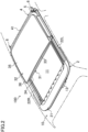
- FIG. 1 is a perspective view of a sliding roof apparatus 100 when a movable panel 31 is in a fully-closed state.
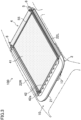
- FIG. 2 is a perspective view of the sliding roof apparatus 100 when the movable panel 31 is in a fully-open state.
- front the front side in a longitudinal direction of a vehicle
- rear the rear side in the longitudinal direction of the vehicle
- left the left side in a vehicle width direction
- right the right side in the vehicle width direction
- the sliding roof apparatus 100 is disposed at an opening 11 formed in a roof 10 of a vehicle.
- the sliding roof apparatus 100 includes a frame 2 extending according to the edge of the opening 11, the movable panel 31 movably attached to the frame 2, a fixed panel 32 fixed to the frame 2, and a roll-screen device 4 provided on the roof 10 inside a vehicle compartment.
- the movable panel 31 is configured to open/close the opening 11.
- the movable panel 31 covers a front part of the opening 11.
- the fixed panel 32 covers a rear part of the opening 11.
- the opening 11 is fully closed by the movable panel 31 and the fixed panel 32.
- a rear end part of the movable panel 31 is at a lower level in an open state than in the fully-closed state, and is drawn to below the fixed panel 32 in the open state. Referring to FIG. 2 , in the fully-open state in which the movable panel 31 is opened to the maximum extent, the movable panel 31 and the fixed panel 32 substantially overlap with each other, and the opening 11 is opened.
- the movable panel 31 is in a tilted state. In the tilted state, the movable panel 31 tilts such that a rear edge thereof is above a front edge of the fixed panel 32, and a clearance for ventilation is formed between the rear edge of the movable panel 31 and the front edge of the fixed panel 32.
- the movable panel 31 includes a substantially rectangular glass panel 33 and a weatherstrip 34 provided along the periphery of the glass panel 33.
- the fixed panel 32 includes a substantially rectangular glass panel 35 and a weatherstrip 36 provided along the periphery of the glass panel 35.
- the glass panel 33 and the glass panel 35 are transparent, and serve as a transparent section through which light passes.
- the movable panel 31 and the fixed panel 32 are an example of a window section.
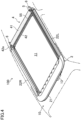
- FIG. 3 is a perspective view of the sliding roof apparatus 100 in the state in which the movable panel 31 and the fixed panel 32 are detached and in which the roll-screen device 4 is in an unrolled state.
- FIG. 4 is a perspective view of the sliding roof apparatus 100 in the state in which the movable panel 31 and the fixed panel 32 are detached and in which the roll-screen device 4 is in a rolled-up state.
- the frame 2 includes a front frame 21 extending in the substantially vehicle width direction, and right and left guide rails 22R, 22L extending in the longitudinal direction.
- the right guide rail 22R and the left guide rail 22L are made of an aluminum alloy.
- the right guide rail 22R and the left guide rail 22L are configured to be bilaterally symmetric with each other.
- the right and left guide rails 22R, 22L are sometime simply referred to as a "guide rail 22" or "guide rails 22" without distinction.
- a plurality of push-pull cables 12 lie in the front frame 21, the right guide rail 22R, and the left guide rail 22L (see FIG. 1 ).
- the push-pull cable12 is a geared cable whose outer circumferential surface is formed with a gear section.
- a drive motor 13 configured to drive the push-pull cables 12 is attached to the front frame 21. The push-pull cables 12 engage with the drive motor 13.
- the movable panel 31 is slidably connected to the right guide rail 22R and the left guide rail 22L through right and left connection members (not shown in the figure).
- the connection member is provided in the guide rail 22, and engages with a slider (not shown in the figure) driven through the push-pull cable 12.
- the slider is driven through the push-pull cable 12 to slide the connection member along the guide rail 22 and to tilt the connection member up and down. Accordingly, the movable panel 31 slides back and forth, and tilts up and down.
- the roll-screen device 4 is provided below the movable panel 31 and the fixed panel 32. Although will be described in detail later, the roll-screen device 4 is configured such that a light-shielding sheet 41 can be rolled up on a winding roller 5. Referring to FIG. 3 , in a fully-unrolled state in which the light-shielding sheet 41 is fully unrolled from the winding roller 5, the light-shielding sheet 41 shields the movable panel 31 and the fixed panel 32 from light, i.e., blocks light from entering the vehicle compartment from the outside through the movable panel 31 and the fixed panel 32. On the other hand, in the rolled-up state in which the light-shielding sheet 41 is rolled up on the winding roller 5 as illustrated in FIG. 4 , the light-shielding sheet 41 unshields the movable panel 31 and the fixed panel 32, i.e., does not block light from entering the vehicle compartment from the outside through the movable panel 31 and the fixed panel 32.
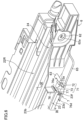
- FIG. 5 is a perspective view of the roll-screen device 4 from the outside.
- FIG. 6 is a perspective view of the roll-screen device 4 from the inside. Note that the light-shielding sheet 41, the winding roller 5, and a depressing member 55 are not shown in FIG. 6 .
- the roll-screen device 4 is an electric roll-screen device.
- the roll-screen device 4 includes the light-shielding sheet 41, the winding roller 5 on which the light-shielding sheet 41 can be rolled up, two support blocks 6 configured to support the winding roller 5, guide sections 7 each provided in a corresponding one of the support blocks 6 and each configured to guide, to a corresponding one of the guide rails 22, the light-shielding sheet 41 drawn from the winding roller 5, and the depressing member 55 configured to guide the light-shield ing sheet 41 to reduce uplifting of the light-shielding sheet 41.
- the right guide rail 22R and the left guide rail 22L form part of the roll-screen device 4.
- the right guide rail 22R and the left guide rail 22L function to guide the light-shielding sheet 41.
- the light-shielding sheet 41 is located below the movable panel 31 and the fixed panel 32 in the state in which the light-shielding sheet 41 is unrolled from the winding roller 5, thereby blocking light from entering the vehicle compartment through the movable panel 31 and the fixed panel 32.
- Each support block 6 is attached to a rear end part of a corresponding one of the right and left guide rails 22R, 22L.
- the support block 6 includes an attachment section 61 to be attached to the guide rail 22, a support section 62 configured to support a shaft 51 of the winding roller 5, a support pin 63 configured to support the depressing member 55, and the guide section 7.
- the support block 6 is an insert-molded component formed by integral molding of a metal plate and resin.
- the attachment section 61 is formed in such a substantially plate shape that the attachment section 61 can be inserted into a rear end of the guide rail 22. Specifically, a passage 24 in which the connection member and slider for the movable panel 31 move is formed on the outside of a later-described sheet passage 23 in the vehicle width direction. The attachment section 61 is inserted into a rear end part of the passage 24. The attachment section 61 is, with a tapping screw 64, fastened to a wall section forming the passage 24
- the support section 62 is formed of a metal plate.
- a through-hole 62a is formed in the support section 62.
- the through-hole 62a is an elongated opening.
- an end part of the shaft 51 of the winding roller 5 has a flat cross-sectional shape, and is inserted into the through-hole 62a. Since the through-hole 62a and the end part of the shaft 51 are not in a perfect circular shape, the support sections 62 unrotatably support the shaft 51.
- the support pin 63 is located on the front relative to the support section 62 and on the rear relative to a rear end of the guide section 7.
- the support pin 63 protrudes inward in the vehicle width direction, and engages with an end part of the depressing member 55.
- the support pins 63 support the depressing member 55.
- the guide section 7 In part of the support block 6 on the front relative to the support pin 63, the guide section 7 is provided. The configuration of the guide section 7 will be described in detail later.
- the winding roller 5 includes the shaft 51, a roller body 52, a biasing mechanism (not shown in the figure) built in the roller body 52.
- the winding roller 5 is attached to the rear end part of the right guide rail 22R through one of the support blocks 6, and is attached to the rear end part of the left guide rail 22L through the other support block 6.
- Each end part of the shaft 51 protrudes outward from a corresponding one of end parts of the roller body 52, and is unrotatably attached to a corresponding one of the support blocks 6.
- the light-shielding sheet 41 is connected to the roller body 52.
- the roller body 52 is, by the biasing mechanism (not shown in the figure), biased in one direction about the shaft 51.
- the light-shielding sheet 41 is rolled up on the roller body 52 by biasing force of the biasing mechanism.
- the light-shielding sheet 41 is a cloth sheet having light shielding properties.
- the light-shielding sheet 41 is in a substantially rectangular shape.
- a rear edge of the light-shielding sheet 41 is connected to the roller body 52.
- a garnish 42 extending in the vehicle width direction is attached to the light-shielding sheet 41 along a front edge thereof.
- a slider 42a is provided at each end of the garnish 42 in the vehicle width direction.
- Each slider 42a is guided by a corresponding one of the right and left guide rails 22R, 22L, and is connected to a corresponding one of the push-pull cables 12.
- the garnish 42 moves back and forth along the guide rails 22.
- the light-shielding sheet 41 is drawn from the roller body 52 against the biasing force of the biasing mechanism.
- the garnish 42 moves to the rear, the light-shielding sheet 41 is rolled up on the roller body 52 by the biasing force of the biasing mechanism.
- each side edge part (hereinafter simply referred to as a "side edge part") of the light-shielding sheet 41 on both sides in the vehicle width direction i.e., each side edge part of the light-shielding sheet 41 on the right and left, is fitted into a corresponding one of the sheet passages 23 of the right and left guide rails 22R, 22L.
- each side edge part of the light-shielding sheet 41 moves back and forth, each side edge part of the light-shielding sheet 41 is guided by a corresponding one of the right and left guide rails 22R, 22L.
- the depressing member 55 depresses one side of the light-shielding sheet 41 drawn from the winding roller 5, thereby adjusting the height position of the light-shielding sheet 41.
- the depressing member 55 is supported by the support blocks 6 in the attitude in which the depressing member 55 extends in the vehicle width direction on the front of the winding roller 5.
- the depressing member 55 is located at the substantially same level as that of the sheet passages 23.
- the depressing member 55 is made of an aluminum alloy.
- the shaft 51 of the winding roller 5 is disposed at a level higher than that of the sheet passages 23, and the light-shielding sheet 41 winded into a roll is drawn from above the winding roller 5 toward the front.
- the light-shielding sheet 41 drawn from the winding roller 5 obliquely downwardly extends from the position higher than the sheet passages 23 toward the front to enter the sheet passages 23.
- the light-shielding sheet 41 passes below the depressing member 55 such that the depressing member 55 holds the light-shielding sheet 41 at the substantially same level as that of the sheet passages 23.
- the light-shielding sheet 41 warps upward from rear ends of the sheet passages 23 to the winding roller 5, resulting in degradation of the appearance of the light-shielding sheet 41 inside the vehicle compartment.
- part of the light-shielding sheet 41 which has been just drawn from the winding roller 5 is held downward by the depressing member 55.
- uplifting in part of the light-shielding sheet 41 near the winding roller 5 is reduced, and the appearance of the light-shielding sheet 41 inside the vehicle compartment is enhanced.
- the level of the light-shielding sheet 41 right before the light-shielding sheet 41 enters the sheet passages 23 can be close to that of the sheet passages 23, the light-shielding sheet 41 can be smoothly enter the sheet passages 23.
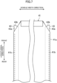
- FIG. 7 is a plan view of the light-shielding sheet 41.
- FIG. 8 is a cross-sectional view of the sheet passages 23 and the light-shielding sheet 41.
- the light-shielding sheet 41 includes a rectangular sheet body 41a and engagement belts 43 each extending in the longitudinal direction along a corresponding one of side edge parts of the sheet body 41a in the vehicle width direction, i.e., along a corresponding one of right and left side edge parts of the sheet body 41a.
- the engagement belt 43 is formed as a member different from the sheet body 41a.
- the engagement belt 43 is connected to the sheet body 41a at a seam 41b.
- the seam 41b is formed relatively on the outside in the vehicle width direction in the engagement belt 43.
- the engagement belt 43 is made of, e.g., resin.
- the material of the engagement belt 43 is not limited to resin, and the engagement belt 43 may be made of an elastic body such as rubber.
- the engagement belt 43 may be formed in such a manner that the side edge part of the sheet body 41a is folded back. That is, the engagement belt 43 may be formed integrally with the sheet body 41a.
- the engagement belt 43 is configured such that at least an inner edge part of the engagement belt 43 in the vehicle width direction is apart from the sheet body 41a to form a clearance between the inner edge part of the engagement belt 43 and the sheet body 41a. Since the seam 41b is formed relatively on the outside in the vehicle width direction in the engagement belt 43, the clearance is easily formed between the inner edge part of the engagement belt 43 in the vehicle width direction and the sheet body 41a.
- a tip end part 43a of the engagement belt 43 which is a forefront of the engagement belt 43 upon entering of the engagement belt 43 into the guide rail 22 is not sewn to the sheet body 41a. That is, the tip end part 43a of the engagement belt 43 is not connected to the sheet body 41a, and is free from the sheet body 41a.
- the tip end part 43a of the engagement belt 43 partially protrudes out from the sheet body 41a. Specifically, a corner part between a front edge and a side edge of the sheet body 41a is obliquely cut off. The tip end part 43a of the engagement belt 43 protrudes out from the oblique edge of the sheet body 41a toward the front. Note that not only part of the tip end part 43a of the engagement belt 43 protruding out from the sheet body 41a but also part of the tip end part 43a of the engagement belt 43 lying on the sheet body 41a are not sewn to the sheet body 41a.
- a tip edge 43b of the engagement belt 43 is not perpendicular to the longitudinal direction (i.e., not parallel to the vehicle width direction), but is inclined relative to the longitudinal direction (i.e., inclined relative to the vehicle width direction). Specifically, the tip edge 43b of the engagement belt 43 is inclined so as to extend forward and outward in the vehicle width direction.
- the following wall sections form the sheet passage 23: a vertical wall section 23a located on the outside of the side edge part of the light-shielding sheet 41 in the vehicle width direction and standing in the vertical direction; an upper wall section 23b extending inward in the vehicle width direction from an upper end of the vertical wall 23a; a lower wall section 23c extending inward in the vehicle width direction from a lower end of the vertical wall 23a; and an engagement wall section 23d extending upward from an inner end of the lower wall section 23c in the vehicle width direction. All of the vertical wall section 23a, the upper wall section 23b, the lower wall section 23c, and the engagement wall section 23d extend in the longitudinal direction.
- the lower wall section 23c includes a step, and an inner part of the lower wall section 23c in the vehicle width direction is located lower than an outer part of the lower wall section 23c in the vehicle width direction.
- the engagement wall section 23d is inclined so as to extend upward and outward in the vehicle width direction.
- the lower wall section 23c extends inward in the vehicle width direction beyond the upper wall section 23b. That is, the engagement wall section 23d is located on the inside in the vehicle width direction relative to an inner edge of the upper wall section 23b in the vehicle width direction. Thus, the inner edge of the upper wall section 23b in the vehicle width direction and an upper edge of the engagement wall section 23d form a slit 23e extending in the longitudinal direction, and the sheet passage 23 opens at the slit 23e.
- the side edge part of the sheet body 41a and the engagement belt 43 are inserted into the sheet passage 23 through the slit 23e.
- the upper wall section 23b faces an upper surface of the side edge part of the sheet body 41a
- the lower wall section 23c faces a lower surface of the engagement belt 43.
- the engagement wall section 23d is located below the sheet body 41a on the inside of the engagement belt 43 in the vehicle width direction.
- the sheet passage 23 houses the side edge part of the sheet body 41a and the engagement belt 43, and guides the side edge part of the sheet body 41a and the engagement belt 43 in the longitudinal direction.
- the sheet body 41a is guided in the longitudinal direction while slidably contacting an upper end of the engagement wall section 23d and the upper wall section 23b.
- the engagement wall section 23d is located on the inside of the engagement belt 43 in the vehicle width direction, and engages with the engagement belt 43.
- the engagement belt 43 provided on the sheet body 41a and the engagement wall section 23d provided in the sheet passage 23 prevents the sheet body 41a from disengaging from the sheet passage 23, i.e., prevents the light-shielding sheet 41 from falling out of the sheet passage 23.
- the right and left side edge parts of the light-shielding sheet 41 move inward in the vehicle width direction when, e.g., a middle part of the light-shielding sheet 41 in the vehicle width direction warps downward due to the weight thereof.
- the light-shielding sheet 41 moves toward either right or left, one of the side edge parts of the light-shielding sheet 41 moves inward in the vehicle width direction.
- the engagement wall section 23d is located on the inside of the engagement belt 43 in the vehicle width direction, the engagement belt 43 is caught by the engagement wall section 23d, and therefore inward movement of the light-shielding sheet 41 in the vehicle width direction is reduced or prevented.
- engagement between the light-shielding sheet 41 and each sheet passage 23 is maintained.
- the light-shielding sheet 41 configured as described above When the light-shielding sheet 41 configured as described above is rolled up on the winding roller 5, the light-shielding sheet 41 comes out of the sheet passages 23, and is not guided along the sheet passages 23. In the state (i.e., the rolled-up state) in which the light-shielding sheet 41 is fully rolled up on the winding roller 5, the entirety of the light-shielding sheet 41 is outside the sheet passages 23. In the state in which the light-shielding sheet 41 is rolled up on the winding roller 5, the sheet body 41a and each engagement belt 43 lie on each other.
- each side edge part of the sheet body 41a is housed in a corresponding one of the sheet passages 23, the other part of the sheet body 41a extends out of each sheet passage 23 through a corresponding one of the slits 23e, and the entirety of each engagement belt 43 is housed in a corresponding one of the sheet passages 23.
- the guide section 7 is provided, which is configured to properly guide the light-shielding sheet 41 drawn from the winding roller 5 into the guide rail 22. Referring to FIG. 6 , the guide section 7 causes the light-shielding sheet 41 to enter the sheet passage 23 through an entrance port 23f formed at the rear end of the guide rail 22.
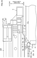
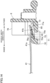
- FIG. 9 is a cross-sectional view of the guide rail 22 along an IX-IX line illustrated in FIG. 6 .
- FIG. 10 is a plan view of the roll-screen device 4 mainly illustrating the guide section 7.
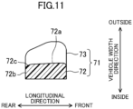
- FIG. 11 is a bottom view of a guide piece 71 in a horizontal cross section of an inner wall 72.
- the guide section 7 includes the guide piece 71 configured to put distance between the engagement belt 43 and the sheet body 41a before the light-shielding sheet 41 enters the guide rail 22, and a guide wall 76 provided closer to the guide rail 22 relative to the guide piece 71 and configured to guide the light-shielding sheet 41 to the entrance port 23f.
- the guide piece 71 is provided on a horizontal wall 65 of the support block 6.
- the guide piece 71 includes the inner wall 72 extending upward from the horizontal wall 65, and a separation wall 73 connected to the inner wall 72.
- the inner wall 72 is configured to guide the engagement belt 43 and determine the position of the engagement belt 43 in the vehicle width direction.
- a surface (hereinafter referred to as an "outer surface") 72a of the inner wall 72 facing outward in the vehicle width direction guides the engagement belt 43 such that the engagement belt 43 passes on the outside of the outer surface 72a in the vehicle width direction.
- the outer surface 72a is located on the outside of the engagement wall section 23d of the sheet passage 23 in the vehicle width direction. That is, the inner wall 72 guides the engagement belt 43 toward the outside of the engagement wall section 23d in the vehicle width direction.
- the outer surface 72a is inclined inward in the vehicle width direction with decreasing distance to the winding roller 5, i.e., is inclined so as to extend backward and inward in the vehicle width direction.
- a ridge section 72c formed between the outer surface 72a and a surface 72b of the inner wall 72 facing the winding roller 5 has a curved surface.
- the separation wall 73 extends, in the substantially horizontal direction, from the inner wall 72 toward the outside in the vehicle width direction.
- the separation wall 73 enters between the sheet body 41a and the engagement belt 43 to put distance between the light-shielding sheet 41 and the engagement belt 43.
- the separation wall 73 is formed thinner toward the outside in the vehicle width direction and toward the rear.
- an opening 73a larger than the projection shape of the separation wall 73 on the horizontal wall 65 is formed in the horizontal wall 65. Since the opening 73a is formed, the guide piece 71 can be easily formed.
- the guide wall 76 is adjacent to the rear end of the guide rail 22.
- a guide opening 77 facing the entrance port 23f of the guide rail 22 is formed in the guide wall 76.
- the guide opening 77 is in a shape corresponding to the entrance port 23f of the guide rail 22.
- an opening edge 77a of the guide opening 77 includes an upper part 77b extending in the horizontal direction, a lower part 77c facing the upper part 77b, and a connection part 77d connecting between an outer end of the upper part 77b in the vehicle width direction and an outer end of the lower part 77c in the vehicle width direction.
- the lower part 77c is in a stepped shape, and an inner part of the lower part 77c in the vehicle width direction is located lower than an outer part of the lower part 77c in the vehicle width direction.
- the guide opening 77 formed as just described is smaller than the entrance port 23f. That is, when the guide opening 77 is viewed from the rear, the opening edge of the entrance port 23f cannot be viewed.
- an inclined surface 76a is formed at the guide wall 76 to guide the light-shielding sheet 41 to the guide opening 77.
- the inclined surface 76a is a rear surface (i.e., a surface of the guide wall 76 opposite to the entrance port 23f) of the guide wall 76 formed above the guide opening 77.
- the inclined surface 76a is inclined so as to extend downward and forward.
- the inclined surface 76a continues to the upper part 77b of the opening edge 77a.
- a first engagement section 76c and a second engagement section 76d engaged with the guide rail 22 when the support block 6 is attached to the guide rail 22 are provided on a surface of the guide wall 76 close to the guide rail 22.
- the first engagement section 76c engages with the upper wall section 23b at an upper surface thereof.
- the second engagement section 76d engages with the lower wall section 23c at a lower surface thereof.
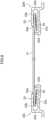
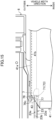
- FIG. 12 is a side view of the roll-screen device 4 from the inside. Note that FIG. 12 illustrates the light-shielding sheet 41 and the winding roller 5 in a cross section extending in the longitudinal direction and the vertical direction.
- FIGS. 13(A) and 13(B) are views illustrating the state in which the light-shielding sheet 41 is about to engage with the guide pieces 71.
- FIG. 13(A) is a view of the light-shielding sheet 41 and the guide piece 71 from the above, and FIG.
- FIG. 13(B) is a view of the light-shielding sheet 41 and the guide piece 71 from the below.
- FIG. 14 is a cross-sectional view illustrating the state in which the separation wall 73 is interposed between the sheet body 41a and the engagement belt 43.
- FIG. 15 is a view illustrating the state in which the light-shielding sheet 41 have entered the sheet passage 23 through the guide opening 77.
- the light-shielding sheet 41 extends, in the rolled-up state, obliquely downward from the winding roller 5 to the depressing member 55 (not shown in FIG. 12 ), and is winded on the depressing member 55. That is, the light-shielding sheet 41 is drawn obliquely to an extension direction (i.e., the longitudinal direction) of the guide rails 22 from the winding roller 5. After being bent at the position of the depressing member 55, the light-shielding sheet 41 extends in the extension direction of the guide rails 22, and then enters the guide rails 22.
- an extension direction i.e., the longitudinal direction
- the light-shielding sheet 41 is bent such that the engagement belt 43 is on the outside and that the sheet body 41a is on the inside.
- a tip end part of the light-shielding sheet 41 is located near the depressing member 55.
- a tip end part of the sheet body 41a is winded on the depressing member 55.
- the tip end part 43a of the engagement belt 43 is not sewn to the sheet body 41a.
- the tip end part 43a of the engagement belt 43 extends obliquely downward as in part of the engagement belt 43 between the winding roller 5 and the depressing member 55. Accordingly, the tip end part 43a of the engagement belt 43 is separated from the sheet body 41a.
- the tip end part 43a of the engagement belt 43 contacts the horizontal wall 65 of the support block 6, and is located lower than the separation wall 73 of the guide piece 71.
- the light-shielding sheet 41 is substantially horizontally drawn from the foregoing state. Referring to FIG. 13 , the sheet body 41a moves over the separation wall 73 of the guide pieces 71. On the other hand, the tip end part 43a of the engagement belt 43 enters below the separation wall 73. Thus, the separation wall 73 enters, from the forefront, between the sheet body 41a and the engagement belt 43.
- the tip end part 43a of the engagement belt 43 which is a free end, i.e., which is not connected to the sheet body 41a, allows the separation wall 73 to smoothly enter between the sheet body 41a and the engagement belt 43. Moreover, the tip end part 43a of the engagement belt 43 protrudes out from the sheet body 41a toward the front. This allows the engagement belt 43 to easily engage with the guide piece 71.
- the separation wall 73 Since the separation wall 73 is formed thinner toward the rear, the separation wall 73 can smoothly enter between the sheet body 41a and the engagement belt 43 moving from the rear of the separation wall 73.
- the separation wall 73 is, from the inside in the vehicle width direction, inserted between the sheet body 41a and the engagement belt 43. This causes the inner edge part of the engagement belt 43 in the vehicle width direction to separate from the sheet body 41a.
- the engagement belt 43 can be farther away from the sheet body 41a on the inside in the vehicle width direction than on the outside in the vehicle width direction.
- an outer end part of the engagement belt 43 in the vehicle width direction is connected to the sheet body 41a, and the separation wall 73 is formed thinner toward the outside in the vehicle width direction. This allows the separation wall 73 to smoothly enter between the sheet body 41a and the engagement belt 43.
- the position of the engagement belt 43 in the vehicle width direction is determined by the inner wall 72 of the guide piece 71. That is, when the engagement belt 43 is located relatively on the inside in the vehicle width direction, the engagement belt 43 contacts the inner wall 72 of the guide piece 71 as illustrated in FIGS. 13(B) and 14 .
- the inner wall 72 guides the engagement belt 43 such that the engagement belt 43 passes on the outside of the inner wall 72 in the vehicle width direction.
- the outer surface 72a of the inner wall 72 is inclined so as to extend backward and inward in the vehicle width direction.
- the engagement belt 43 is gradually guided toward the outside in the vehicle width direction.
- the engagement belt 43 is guided to the position on the outside of the engagement wall section 23d in the vehicle width direction in the sheet passage 23.
- the ridge section 72c of the inner wall 72 on the outer rear side in the vehicle width direction defines the curved surface.
- the tip edge 43b of the engagement belt 43 is inclined so as to extend forward and outward in the vehicle width direction. Thus, when the tip edge 43b of the engagement belt 43 protruding toward the front comes into contact with the inner wall 72, the engagement belt 43 is guided to the outside in the vehicle width direction along the tip edge 43b.
- a vehicle widthwise distance between the outer surface 72a of the inner wall 72 and the outermost part of the separation wall 73 in the vehicle width direction is shorter than a vehicle widthwise distance between an inner edge of the engagement belt 43 in the vehicle width direction and the seam 41b.
- the light-shielding sheet 41 reaches the guide wall 76, and enters the guide opening 77.
- the sheet body 41a is guided to the guide opening 77 by the inclined surface 76a of the guide wall 76.
- the sheet body 41a and the engagement belt 43 vertically separated from each other by the guide piece 71 approach each other so that the sheet body 41a and the engagement belt 43 can enter the guide opening 77 along the inclined surface 76a.
- the engagement belt 43 may come into contact with the edge of the opening 73a when the engagement belt 43 passes through the space below the separation wall 73.
- the tip edge 43b of the engagement belt 43 is formed parallel to the vehicle width direction, there is a possibility that the tip edge 43b of the engagement belt 43 is caught by the edge of the opening 73a and therefore the light-shielding sheet 41 cannot be smoothly guided to the guide rail 22.
- the tip edge 43b of the engagement belt 43 is inclined relative to the vehicle width direction. Thus, even if the tip edge 43b of the engagement belt 43 contacts the edge of the opening 73a, the engagement belt 43 moves in the vehicle width direction while moving forward.
- the tip edge 43b of the engagement belt 43 can be prevented from being caught by the edge of the opening 73a, and therefore the light-shielding sheet 41 can be smoothly guided to the guide rail 22.
- the tip edge 43b is inclined so as to extend forward and outward in the vehicle width direction.
- the engagement belt 43 moves outward in the vehicle width direction when moving away from the inner wall 72 in the vehicle width direction. That is, the engagement belt 43 can be guided outward in the vehicle width direction using inclination of the tip edge 43b.
- the sheet body 41a and the engagement belt 43 having passed through the guide opening 77 smoothly enter the sheet passage 23 through the entrance port 23f.
- an outer part of an upper surface 73b of the separation wall 73 in the vehicle width direction is at a level lower than the upper wall section 23b of the sheet passage 23.
- the upper part 77b of the opening edge 77a of the guide opening 77 is set at a level lower than the upper wall section 23b.
- an inner part of the upper surface 73b of the separation wall 73 in the vehicle width direction is at a level higher than the engagement wall section 23d of the sheet passage 23.
- the upper part 77b of the opening edge 77a of the guide opening 77 extends only to an outer part of the separation wall 73 in the vehicle width direction, and does not extend to an inner part of the separation wall 73 in the vehicle width direction and the engagement wall section 23d.
- the sheet body 41a having passed through the guide piece 71 and the guide opening 77 and having entered the sheet passage 23 is below the upper wall section 23b at the position corresponding to the upper wall section 23b, and is over the engagement wall section 23d at the position corresponding to the engagement wall section 23d.
- the sheet body 41a enters the sheet passage 23 without contacting a rear end surface of the guide rail 22. Note that a rear end surface of the engagement wall section 23d is not covered by the guide wall 76, and is exposed. However, part of the sheet body 41a corresponding to the engagement wall section 23d is uplifted by the separation wall 73, and therefore is less likely to contact a rear edge of the engagement wall section 23d.
- a lower surface of the separation wall 73 is at a level lower than the upper end of the engagement wall section 23d.
- the outer surface 72a of the inner wall 72 is positioned on the outside of the engagement wall section 23d in the vehicle width direction.
- the lower part 77c of the opening edge 77a of the guide opening 77 is set at a level higher than the lower wall section 23c of the sheet passage 23.
- the roll-screen device 4 is the roll-screen device provided at the movable panel 31 and the fixed panel 32 which are formed in the roof 10 of the vehicle.
- the roll-screen device 4 includes the winding roller 5; the light-shielding sheet 41 configured to open the movable panel 31 and the fixed panel 32 in the rolled-up state in which the light-shielding sheet 41 is rolled up on the winding roller 5 and to shield the movable panel 31 and the fixed panel 32 from light in the unrolled state in which the light-shielding sheet 41 is unrolled from the rolled-up state; the guide rails 22 provided on both sides of the light-shielding sheet 41 in the vehicle width direction and configured to guide the light-shielding sheet 41 when the light-shielding sheet 41 transitions between the rolled-up state and the unrolled state; and the guide sections 7 configured to allow entrance of the light-shielding sheet 41, which is drawn from the winding roller 5, into the guide rails 22 through the entrance ports 23f provided at the end faces of
- the light-shielding sheet 41 includes the sheet body 41a, and the engagement belts 43 provided at and along both side edges of the sheet body 41a in the vehicle width direction.
- the sheet body 41a and the engagement belts 43 are rolled up on the winding roller 5 such that the sheet body 41a and the engagement belts 43 lie on each other.
- the guide rails 22 include the engagement wall sections 23d located at the vehicle widthwise inner side of the engagement belts 43 and configured to engage with the engagement belts 43 to prevent the light-shielding sheet 41 from falling out of the guide rails 22.
- the guide sections 7 include the guide pieces 71 each configured to put distance between the engagement belt 43 and the sheet body 41a before the light-shielding sheet 41 enters the guide rails 22.
- the light-shielding sheet 41 is guided by the guide rails 22 when the light-shielding sheet 41 transitions between the rolled-up state and the unrolled state.
- the sheet body 41a is prevented from falling out of the guide rail 22.
- the sheet body 41a and the engagement belts 43 lie on each other.
- each side edge part of the light-shielding sheet 41 is guided to a corresponding one of the guide rails 22, and the remaining part of the light-shielding sheet 41 protrudes out from the guide rails 22.
- the light-shielding sheet 41 enters the guide rails 22 with the sheet body 41a and the engagement belts 43 lying on each other, there is a possibility that the engagement belt 43 does not engage with the engagement wall section 23d and protrudes out from the guide rail 22. Accordingly, the light-shielding sheet 41 easily disengages from the guide rails 22, and therefore cannot be properly guided by the guide rails 22.
- the light-shielding sheet 41 when the light-shielding sheet 41 is drawn from the rolled-up state, the light-shielding sheet 41 is guided by the guide sections 7, and then enters the guide rails 22 through the entrance ports 23f each formed at the end face of the guide rail 22.
- the guide piece 71 of the guide section 7 puts distance between the engagement belt 43 and the sheet body 41a.
- the sheet body 41a can move over the engagement wall section 23d with the side edge part of the sheet body 41a being inserted into the sheet passage 23, and the engagement belt 43 can be guided to the outside of the engagement wall section 23d in the vehicle width direction.
- the engagement belt 43 of the light-shielding sheet 41 can engage with the guide rail 22, specifically the engagement wall section 23d.
- Each guide section 7 is provided closer to the guide rail 22 than the guide piece 71 is, and further includes the guide wall 76 in which the guide opening 77 configured to guide the light-shielding sheet 41 is formed such that the light-shielding sheet 41 does not come into contact with the rear end surface of the guide rail 22 when the light-shielding sheet 41 enters the entrance port 23f.
- the guide opening 77 is smaller than the entrance port 23f.
- the light-shielding sheet 41 before entering the entrance port 23f, the light-shielding sheet 41 is guided by the guide opening 77 smaller than the entrance port 23f so as not to contact the rear end surface of the guide rail 22. This can prevent the light-shielding sheet 41 from being caught by the rear end surface of the guide rail 22, and can prevent the light-shielding sheet 41 from being damaged by the rear end surface of the guide rail 22.
- the guide piece 71 puts distance between the sheet body 41a of the light-shielding sheet 41 and the engagement belt 43, and the light-shielding sheet 41 having passed through the guide piece 71 is guided by the guide opening 77. This can effectively prevent the light-shielding sheet 41 and the rear end surface of the guide rail 22 from contacting each other.
- Each guide piece 71 includes the inner wall 72 located at the vehicle width wise inner side of the engagement belt 43, and the separation wall 73 connected to the inner wall 72 and entering between the sheet body 41a and the engagement belt 43.
- the separation wall 73 of the guide piece 71 puts distance between the sheet body 41a and the engagement belt 43. Moreover, since the inner wall 72 is provided in the guide piece 71, the position of the light-shielding sheet 41 in the vehicle width direction can be determined when the light-shielding sheet 41 passes through the guide piece 71.
- the inner wall 72 has the outer surface 72a facing outward in the vehicle width direction, where the outer surface 72a is inclined inward in the vehicle width direction with decreasing distance to the winding roller 5.
- the light-shielding sheet 41 when passing through the guide piece 71, the light-shielding sheet 41 is gradually guided outward in the vehicle width direction by the inner wall 72. That is, drawing of the light-shielding sheet 41 and determination on the position of the light-shielding sheet 41 in the vehicle width direction can be smoothly performed.
- the inner wall 72 has the ridge section 72c formed by the outer surface 72a facing outward in the vehicle width direction and the surface 72b facing the winding roller 5, where the ridge section 72c is a curved surface.
- the light-shielding sheet 41 can be smoothly guided to the outer surface 72a along the curved ridge section 72c.
- the engagement belts 43 each have the tip edge 43b serving as the forefront in entering the guide rail 22, where the tip edge 43b is inclined such that the end of the tip edge 43b at the vehicle widthwise outer side is located forward.
- the tip edge 43b of the engagement belt 43 is inclined.
- the engagement belt 43 moves, along inclination of the tip edge 43b, in the vehicle width direction while moving forward. This can prevent the engagement belt 43 from being caught by another member.
- the tip edge 43b of the engagement belt 43 is inclined such that the end of the tip edge 43b at the vehicle widthwise outer side is located forward, the engagement belt 43 can move outward in the vehicle width direction when the tip edge 43b comes into contact with another member.
- Such a direction is coincident with the direction in which the engagement belt 43 is guided to engage with the engagement wall section 23d. That is, inclination of the tip edge 43b also allows the engagement belt 43 to be guided outward in the vehicle width direction.
- the foregoing embodiment may have the following configurations.
- the movable panel 31 and the fixed panel 32 are provided as an example of the window section, but the window section is not limited to the movable panel 31 and the fixed panel 32.
- the window section is not necessarily openable, and may be a glass panel fixed to the opening of the roof.
- the roll-screen device 4 is driven by the drive motor 13 through the push-pull cables 12, but is not limited to such a configuration.
- the roll-screen device 4 may be manually opened/closed, or may be opened/closed by a drive source other than the drive motor.
- the configuration of the light-shielding sheet 41 is not limited to the foregoing.
- the engagement belt 43 may be formed in such a manner that the side edge part of the sheet body 41a is folded back.
- the engagement belt 43 is provided below the sheet body 41a, but may be provided above the sheet body 41a.
- the engagement wall section 23d is provided so as to extend downward from the upper wall section 23b.
- the configuration of the engagement belt 43 is not limited to the foregoing.
- the tip end part 43a of the engagement belt 43 does not necessarily protrude out from the sheet body 41a.
- the tip end part 43a of the engagement belt 43 may be connected to the sheet body 41a.
- the tip edge 43b of the engagement belt 43 may be inclined such that the end of the tip edge 43b at the vehicle widthwise inner side is located forward.
- the tip edge 43b of the engagement belt 43 may be parallel to the vehicle width direction.
- the foregoing advantages can be realized by the foregoing configuration of the engagement belt 43.
- the configuration of the sheet passage 23 is not limited to the foregoing. As long as the engagement wall section 23d to be engaged with the engagement belt 43 is provided in the sheet passage 23 so that the light-shielding sheet 41 can be guided, optional configuration of the sheet passage 23 can be employed.
- the light-shielding sheet 41 is obliquely downwardly drawn from the winding roller 5 toward the front, and then changes the extension direction thereof to the longitudinal direction (i.e., the horizontal direction) to enter the guide rails 22.
- the light-shielding sheet 41 is not limited to such a configuration.
- the light-shielding sheet 41 may be obliquely upwardly drawn from the winding roller 5 toward the front, and then may change the extension direction thereof to the longitudinal direction to enter the guide rails 22.
- the light-shielding sheet 41 may be substantially horizontally drawn from the winding roller 5 to enter the guide rails 22.
- the configuration of the guide section 7 is not limited to the foregoing.
- the guide section 7 may be provided in a member other than the support block 6.
- the guide section 7 does not necessarily include the guide wall 76.
- the technique disclosed herein is useful for the roll-screen device configured to shield the window section formed in the roof of the vehicle from light.
Description
- The technique disclosed herein relates to a roll-screen device configured to shield a window section formed in a roof of a vehicle from light. A device of this kind is known from
EP 2447098 A . -
Patent Document 1 discloses a roll-screen device configured to shield a window section of a roof panel from light. The roll-screen device includes a light-shielding sheet and a pair of guide rails configured to guide the light-shielding sheet. An engagement belt to be engaged with the guide rail is formed at part of the light-shielding sheet guided by the guide rail. Each engagement belt is formed in such a manner that the light-shielding sheet is folded back at a side edge thereof. The light-shielding sheet can be rolled up on a winding roller. A guide section configured to guide the light-shielding sheet drawn from the winding roller to the guide rail is provided at a rear end of the guide rail. - [Patent Document 1] Japanese Unexamined Patent Publication No.
2012-091649 - As in the foregoing configuration in which the engagement belt to be engaged with the guide rail is formed at the side edge part of the light-shielding sheet guided by the guide rail, when the light-shielding sheet drawn from the winding roller is guided to the guide rails, it is necessary not only to cause the side edge part of the light-shielding sheet to enter the guide rail, but also to cause the engagement belt to properly engage with the guide rail. That is, it is necessary that only each side edge part of a body of the light-shielding sheet is housed in a corresponding one of the guide rails and that the entirety of each engagement belt is housed in a corresponding one of the guide rails to engage with a wall section of the corresponding one of the guide rails. If the engagement belt cannot be properly engaged with the guide rail, the light-shielding sheet is easily fallen out of the guide rail.
- The technique disclosed herein is intended to engage each engagement belt of a light-shieling sheet with a corresponding one of guide rails when the light-shielding sheet enters the guide rails.
- The technique disclosed herein is intended for a roll-screen device provided at a window section formed in a roof of a vehicle. The roll-screen device includes a winding roller; a light-shielding sheet configured to open the window section in a rolled-up state in which the light-shielding sheet is rolled up on the winding roller and to shield the window section from light in an unrolled state in which the light-shielding sheet is unrolled from the rolled-up state; guide rails provided on both sides of the light-shielding sheet in a vehicle width direction and configured to guide the light-shielding sheet when the light-shielding sheet transitions between the rolled-up state and unrolled state; and guide sections configured to allow entrance of side edges at both sides of the light-shielding sheet, which is drawn from the winding roller, in the vehicle width direction into the guide rails through entrance ports provided at end faces of the guide rails. The light-shielding sheet includes a sheet body, and engagement belts provided at and along side edges at both sides of the sheet body in the vehicle width direction. The sheet body and the engagement belts are rolled up on the winding roller such that the sheet body and the engagement belts lie on each other. The guide rails include engagement wall sections located at a vehicle widthwise inner side of the engagement belts and configured to engage with the engagement belts to prevent the light-shielding sheet from falling out of the guide rails. The guide sections include guide pieces each configured to put distance between the engagement belt and the sheet body before the light-shielding sheet enters the guide rails. Each guide piece includes an inner wall located at the vehicle widthwise inner side of the engagement belt, and a separation wall connected to the inner wall and located between the sheet body and the engagement belt for the unrolled state of the light-shielding sheet.
- According to the roll-screen device, the guide piece puts distance between the engagement belt and the sheet body before the light-shielding sheet enters the guide rail. Thus, when the light-shielding sheet enters the guide rails, each engagement belt of the light-shielding sheet can be engaged with a corresponding one of the guide rails.
-
- [
FIG. 1] FIG. 1 is a perspective view of a sliding roof apparatus when a movable panel is in a fully-closed state. - [
FIG. 2] FIG. 2 is a perspective view of the sliding roof apparatus when the movable panel is in a fully-open state. - [
FIG. 3] FIG. 3 is a perspective view of the sliding roof apparatus in the state in which the movable panel and a fixed panel are detached and in which a roll-screen device is in an unrolled state. - [
FIG. 4] FIG. 4 is a perspective view of the sliding roof apparatus in the state in which the movable panel and the fixed panel are detached and in which the roll-screen device is in a rolled-up state. - [
FIG. 5] FIG. 5 is a perspective view of the roll-screen device from the outside. - [
FIG. 6] FIG. 6 is a perspective view of the roll-screen device from the inside. - [
FIG. 7] FIG. 7 is a plan view of a light-shielding sheet. - [
FIG. 8] FIG. 8 is a cross-sectional view of sheet passages and the light-shielding sheet. - [
FIG. 9] FIG. 9 is a cross-sectional view of a guide rail along an IX-IX line illustrated inFIG. 6 . - [
FIG. 10] FIG. 10 is a plan view of the roll-screen device mainly illustrating a guide section. - [
FIG. 11] FIG. 11 is a bottom view of a guide piece in a horizontal cross section of an inner wall. - [
FIG. 12] FIG. 12 is a side view of the roll-screen device from the inside. - [
FIG. 13] FIGS. 13(A) and 13(B) are views illustrating the state in which the light-shielding sheet is about to engage with the guide pieces.FIG. 13(A) is a view of the light-shielding sheet and the guide piece from the above.FIG. 13(B) is a view of the light-shielding sheet and the guide piece from the below. - [
FIG. 14] FIG. 14 is a cross-sectional view illustrating the state in which a separation wall is interposed between a sheet body and the engagement belt. - [
FIG. 15] FIG. 15 is a view illustrating the state in which the light-shielding sheet have entered the sheet passage through the guide opening. - An example embodiment will be described in detail below with reference to drawings.
-
FIG. 1 is a perspective view of a slidingroof apparatus 100 when amovable panel 31 is in a fully-closed state.FIG. 2 is a perspective view of thesliding roof apparatus 100 when themovable panel 31 is in a fully-open state. For the sake of simplicity of description, in the present specification, the front side in a longitudinal direction of a vehicle is referred to as "front," the rear side in the longitudinal direction of the vehicle is referred to as "rear," the left side in a vehicle width direction is referred to as "left," and the right side in the vehicle width direction is referred to as "right." - The sliding
roof apparatus 100 is disposed at an opening 11 formed in aroof 10 of a vehicle. Thesliding roof apparatus 100 includes aframe 2 extending according to the edge of theopening 11, themovable panel 31 movably attached to theframe 2, afixed panel 32 fixed to theframe 2, and a roll-screen device 4 provided on theroof 10 inside a vehicle compartment. Themovable panel 31 is configured to open/close theopening 11. - In the fully-closed state illustrated in
FIG. 1 , themovable panel 31 covers a front part of theopening 11. Thefixed panel 32 covers a rear part of theopening 11. In the fully-closed state, theopening 11 is fully closed by themovable panel 31 and thefixed panel 32. - A rear end part of the
movable panel 31 is at a lower level in an open state than in the fully-closed state, and is drawn to below thefixed panel 32 in the open state. Referring toFIG. 2 , in the fully-open state in which themovable panel 31 is opened to the maximum extent, themovable panel 31 and thefixed panel 32 substantially overlap with each other, and theopening 11 is opened. - Although not shown in the figure, the
movable panel 31 is in a tilted state. In the tilted state, themovable panel 31 tilts such that a rear edge thereof is above a front edge of thefixed panel 32, and a clearance for ventilation is formed between the rear edge of themovable panel 31 and the front edge of thefixed panel 32. - The
movable panel 31 includes a substantiallyrectangular glass panel 33 and aweatherstrip 34 provided along the periphery of theglass panel 33. Thefixed panel 32 includes a substantiallyrectangular glass panel 35 and aweatherstrip 36 provided along the periphery of theglass panel 35. Theglass panel 33 and theglass panel 35 are transparent, and serve as a transparent section through which light passes. Themovable panel 31 and the fixedpanel 32 are an example of a window section. -
FIG. 3 is a perspective view of the slidingroof apparatus 100 in the state in which themovable panel 31 and the fixedpanel 32 are detached and in which the roll-screen device 4 is in an unrolled state.FIG. 4 is a perspective view of the slidingroof apparatus 100 in the state in which themovable panel 31 and the fixedpanel 32 are detached and in which the roll-screen device 4 is in a rolled-up state. - The
frame 2 includes afront frame 21 extending in the substantially vehicle width direction, and right andleft guide rails right guide rail 22R and theleft guide rail 22L are made of an aluminum alloy. Theright guide rail 22R and theleft guide rail 22L are configured to be bilaterally symmetric with each other. The right andleft guide rails - A plurality of push-
pull cables 12 lie in thefront frame 21, theright guide rail 22R, and theleft guide rail 22L (seeFIG. 1 ). The push-pull cable12 is a geared cable whose outer circumferential surface is formed with a gear section. Adrive motor 13 configured to drive the push-pull cables 12 is attached to thefront frame 21. The push-pull cables 12 engage with thedrive motor 13. - The
movable panel 31 is slidably connected to theright guide rail 22R and theleft guide rail 22L through right and left connection members (not shown in the figure). The connection member is provided in the guide rail 22, and engages with a slider (not shown in the figure) driven through the push-pull cable 12. The slider is driven through the push-pull cable 12 to slide the connection member along the guide rail 22 and to tilt the connection member up and down. Accordingly, themovable panel 31 slides back and forth, and tilts up and down. - The roll-
screen device 4 is provided below themovable panel 31 and the fixedpanel 32. Although will be described in detail later, the roll-screen device 4 is configured such that a light-shieldingsheet 41 can be rolled up on a windingroller 5. Referring toFIG. 3 , in a fully-unrolled state in which the light-shieldingsheet 41 is fully unrolled from the windingroller 5, the light-shieldingsheet 41 shields themovable panel 31 and the fixedpanel 32 from light, i.e., blocks light from entering the vehicle compartment from the outside through themovable panel 31 and the fixedpanel 32. On the other hand, in the rolled-up state in which the light-shieldingsheet 41 is rolled up on the windingroller 5 as illustrated inFIG. 4 , the light-shieldingsheet 41 unshields themovable panel 31 and the fixedpanel 32, i.e., does not block light from entering the vehicle compartment from the outside through themovable panel 31 and the fixedpanel 32. - The configuration of the roll-
screen device 4 will be described in detail below.FIG. 5 is a perspective view of the roll-screen device 4 from the outside.FIG. 6 is a perspective view of the roll-screen device 4 from the inside. Note that the light-shieldingsheet 41, the windingroller 5, and adepressing member 55 are not shown inFIG. 6 . - The roll-
screen device 4 is an electric roll-screen device. The roll-screen device 4 includes the light-shieldingsheet 41, the windingroller 5 on which the light-shieldingsheet 41 can be rolled up, twosupport blocks 6 configured to support the windingroller 5, guidesections 7 each provided in a corresponding one of the support blocks 6 and each configured to guide, to a corresponding one of the guide rails 22, the light-shieldingsheet 41 drawn from the windingroller 5, and thedepressing member 55 configured to guide the light-shield ing sheet 41 to reduce uplifting of the light-shieldingsheet 41. Moreover, theright guide rail 22R and theleft guide rail 22L form part of the roll-screen device 4. Theright guide rail 22R and theleft guide rail 22L function to guide the light-shieldingsheet 41. The light-shieldingsheet 41 is located below themovable panel 31 and the fixedpanel 32 in the state in which the light-shieldingsheet 41 is unrolled from the windingroller 5, thereby blocking light from entering the vehicle compartment through themovable panel 31 and the fixedpanel 32. - Each
support block 6 is attached to a rear end part of a corresponding one of the right andleft guide rails support block 6 includes anattachment section 61 to be attached to the guide rail 22, asupport section 62 configured to support ashaft 51 of the windingroller 5, asupport pin 63 configured to support the depressingmember 55, and theguide section 7. Thesupport block 6 is an insert-molded component formed by integral molding of a metal plate and resin. - The
attachment section 61 is formed in such a substantially plate shape that theattachment section 61 can be inserted into a rear end of the guide rail 22. Specifically, apassage 24 in which the connection member and slider for themovable panel 31 move is formed on the outside of a later-describedsheet passage 23 in the vehicle width direction. Theattachment section 61 is inserted into a rear end part of thepassage 24. Theattachment section 61 is, with a tappingscrew 64, fastened to a wall section forming thepassage 24 - The
support section 62 is formed of a metal plate. A through-hole 62a is formed in thesupport section 62. The through-hole 62a is an elongated opening. Referring toFIG. 5 , an end part of theshaft 51 of the windingroller 5 has a flat cross-sectional shape, and is inserted into the through-hole 62a. Since the through-hole 62a and the end part of theshaft 51 are not in a perfect circular shape, thesupport sections 62 unrotatably support theshaft 51. - The
support pin 63 is located on the front relative to thesupport section 62 and on the rear relative to a rear end of theguide section 7. Thesupport pin 63 protrudes inward in the vehicle width direction, and engages with an end part of thedepressing member 55. Thus, the support pins 63 support the depressingmember 55. - In part of the
support block 6 on the front relative to thesupport pin 63, theguide section 7 is provided. The configuration of theguide section 7 will be described in detail later. - The winding
roller 5 includes theshaft 51, aroller body 52, a biasing mechanism (not shown in the figure) built in theroller body 52. In the attitude in which the windingroller 5 extends in the vehicle width direction, the windingroller 5 is attached to the rear end part of theright guide rail 22R through one of the support blocks 6, and is attached to the rear end part of theleft guide rail 22L through theother support block 6. Each end part of theshaft 51 protrudes outward from a corresponding one of end parts of theroller body 52, and is unrotatably attached to a corresponding one of the support blocks 6. The light-shieldingsheet 41 is connected to theroller body 52. Theroller body 52 is, by the biasing mechanism (not shown in the figure), biased in one direction about theshaft 51. Thus, the light-shieldingsheet 41 is rolled up on theroller body 52 by biasing force of the biasing mechanism. - The light-shielding
sheet 41 is a cloth sheet having light shielding properties. The light-shieldingsheet 41 is in a substantially rectangular shape. A rear edge of the light-shieldingsheet 41 is connected to theroller body 52. Referring toFIGS. 3 and4 , agarnish 42 extending in the vehicle width direction is attached to the light-shieldingsheet 41 along a front edge thereof. Aslider 42a is provided at each end of thegarnish 42 in the vehicle width direction. Eachslider 42a is guided by a corresponding one of the right andleft guide rails pull cables 12. That is, when the push-pull cables 12 are driven by thedrive motor 13, thegarnish 42 moves back and forth along the guide rails 22. When thegarnish 42 moves to the front, the light-shieldingsheet 41 is drawn from theroller body 52 against the biasing force of the biasing mechanism. On the other hand, when thegarnish 42 moves to the rear, the light-shieldingsheet 41 is rolled up on theroller body 52 by the biasing force of the biasing mechanism. - Although will be described in detail later, the
sheet passages 23 extending in the longitudinal direction are formed on the inside of the guide rails 22 in the vehicle width direction. Each side edge part (hereinafter simply referred to as a "side edge part") of the light-shieldingsheet 41 on both sides in the vehicle width direction, i.e., each side edge part of the light-shieldingsheet 41 on the right and left, is fitted into a corresponding one of thesheet passages 23 of the right andleft guide rails sheet 41 moves back and forth, each side edge part of the light-shieldingsheet 41 is guided by a corresponding one of the right andleft guide rails - The depressing
member 55 depresses one side of the light-shieldingsheet 41 drawn from the windingroller 5, thereby adjusting the height position of the light-shieldingsheet 41. The depressingmember 55 is supported by the support blocks 6 in the attitude in which thedepressing member 55 extends in the vehicle width direction on the front of the windingroller 5. The depressingmember 55 is located at the substantially same level as that of thesheet passages 23. The depressingmember 55 is made of an aluminum alloy. Theshaft 51 of the windingroller 5 is disposed at a level higher than that of thesheet passages 23, and the light-shieldingsheet 41 winded into a roll is drawn from above the windingroller 5 toward the front. Thus, the light-shieldingsheet 41 drawn from the windingroller 5 obliquely downwardly extends from the position higher than thesheet passages 23 toward the front to enter thesheet passages 23. At this point, the light-shieldingsheet 41 passes below the depressingmember 55 such that the depressingmember 55 holds the light-shieldingsheet 41 at the substantially same level as that of thesheet passages 23. In the absence of thedepressing member 55, the light-shieldingsheet 41 warps upward from rear ends of thesheet passages 23 to the windingroller 5, resulting in degradation of the appearance of the light-shieldingsheet 41 inside the vehicle compartment. On the other hand, part of the light-shieldingsheet 41 which has been just drawn from the windingroller 5 is held downward by the depressingmember 55. Thus, uplifting in part of the light-shieldingsheet 41 near the windingroller 5 is reduced, and the appearance of the light-shieldingsheet 41 inside the vehicle compartment is enhanced. Moreover, since the level of the light-shieldingsheet 41 right before the light-shieldingsheet 41 enters thesheet passages 23 can be close to that of thesheet passages 23, the light-shieldingsheet 41 can be smoothly enter thesheet passages 23. - Next, the structure for guiding the light-shielding
sheet 41 along thesheet passages 23 will be described in detail.FIG. 7 is a plan view of the light-shieldingsheet 41.FIG. 8 is a cross-sectional view of thesheet passages 23 and the light-shieldingsheet 41. - Referring to
FIG. 7 , the light-shieldingsheet 41 includes arectangular sheet body 41a andengagement belts 43 each extending in the longitudinal direction along a corresponding one of side edge parts of thesheet body 41a in the vehicle width direction, i.e., along a corresponding one of right and left side edge parts of thesheet body 41a. Theengagement belt 43 is formed as a member different from thesheet body 41a. Theengagement belt 43 is connected to thesheet body 41a at aseam 41b. Theseam 41b is formed relatively on the outside in the vehicle width direction in theengagement belt 43. Theengagement belt 43 is made of, e.g., resin. However, the material of theengagement belt 43 is not limited to resin, and theengagement belt 43 may be made of an elastic body such as rubber. Alternatively, theengagement belt 43 may be formed in such a manner that the side edge part of thesheet body 41a is folded back. That is, theengagement belt 43 may be formed integrally with thesheet body 41a. - The
engagement belt 43 is configured such that at least an inner edge part of theengagement belt 43 in the vehicle width direction is apart from thesheet body 41a to form a clearance between the inner edge part of theengagement belt 43 and thesheet body 41a. Since theseam 41b is formed relatively on the outside in the vehicle width direction in theengagement belt 43, the clearance is easily formed between the inner edge part of theengagement belt 43 in the vehicle width direction and thesheet body 41a. - A
tip end part 43a of theengagement belt 43 which is a forefront of theengagement belt 43 upon entering of theengagement belt 43 into the guide rail 22 is not sewn to thesheet body 41a. That is, thetip end part 43a of theengagement belt 43 is not connected to thesheet body 41a, and is free from thesheet body 41a. - The
tip end part 43a of theengagement belt 43 partially protrudes out from thesheet body 41a. Specifically, a corner part between a front edge and a side edge of thesheet body 41a is obliquely cut off. Thetip end part 43a of theengagement belt 43 protrudes out from the oblique edge of thesheet body 41a toward the front. Note that not only part of thetip end part 43a of theengagement belt 43 protruding out from thesheet body 41a but also part of thetip end part 43a of theengagement belt 43 lying on thesheet body 41a are not sewn to thesheet body 41a. - A
tip edge 43b of theengagement belt 43 is not perpendicular to the longitudinal direction (i.e., not parallel to the vehicle width direction), but is inclined relative to the longitudinal direction (i.e., inclined relative to the vehicle width direction). Specifically, thetip edge 43b of theengagement belt 43 is inclined so as to extend forward and outward in the vehicle width direction. - Next, the configuration of the
sheet passage 23 will be described. Referring toFIG. 8 , the following wall sections form the sheet passage 23: avertical wall section 23a located on the outside of the side edge part of the light-shieldingsheet 41 in the vehicle width direction and standing in the vertical direction; anupper wall section 23b extending inward in the vehicle width direction from an upper end of thevertical wall 23a; alower wall section 23c extending inward in the vehicle width direction from a lower end of thevertical wall 23a; and anengagement wall section 23d extending upward from an inner end of thelower wall section 23c in the vehicle width direction. All of thevertical wall section 23a, theupper wall section 23b, thelower wall section 23c, and theengagement wall section 23d extend in the longitudinal direction. Thelower wall section 23c includes a step, and an inner part of thelower wall section 23c in the vehicle width direction is located lower than an outer part of thelower wall section 23c in the vehicle width direction. Theengagement wall section 23d is inclined so as to extend upward and outward in the vehicle width direction. - The
lower wall section 23c extends inward in the vehicle width direction beyond theupper wall section 23b. That is, theengagement wall section 23d is located on the inside in the vehicle width direction relative to an inner edge of theupper wall section 23b in the vehicle width direction. Thus, the inner edge of theupper wall section 23b in the vehicle width direction and an upper edge of theengagement wall section 23d form aslit 23e extending in the longitudinal direction, and thesheet passage 23 opens at theslit 23e. - The side edge part of the
sheet body 41a and theengagement belt 43 are inserted into thesheet passage 23 through theslit 23e. In such a state, theupper wall section 23b faces an upper surface of the side edge part of thesheet body 41a, and thelower wall section 23c faces a lower surface of theengagement belt 43. Theengagement wall section 23d is located below thesheet body 41a on the inside of theengagement belt 43 in the vehicle width direction. - As just described, the
sheet passage 23 houses the side edge part of thesheet body 41a and theengagement belt 43, and guides the side edge part of thesheet body 41a and theengagement belt 43 in the longitudinal direction. Typically, thesheet body 41a is guided in the longitudinal direction while slidably contacting an upper end of theengagement wall section 23d and theupper wall section 23b. Theengagement wall section 23d is located on the inside of theengagement belt 43 in the vehicle width direction, and engages with theengagement belt 43. Theengagement belt 43 provided on thesheet body 41a and theengagement wall section 23d provided in thesheet passage 23 prevents thesheet body 41a from disengaging from thesheet passage 23, i.e., prevents the light-shieldingsheet 41 from falling out of thesheet passage 23. Since the light-shieldingsheet 41 has flexibility, the right and left side edge parts of the light-shieldingsheet 41 move inward in the vehicle width direction when, e.g., a middle part of the light-shieldingsheet 41 in the vehicle width direction warps downward due to the weight thereof. When the light-shieldingsheet 41 moves toward either right or left, one of the side edge parts of the light-shieldingsheet 41 moves inward in the vehicle width direction. However, since theengagement wall section 23d is located on the inside of theengagement belt 43 in the vehicle width direction, theengagement belt 43 is caught by theengagement wall section 23d, and therefore inward movement of the light-shieldingsheet 41 in the vehicle width direction is reduced or prevented. Thus, engagement between the light-shieldingsheet 41 and eachsheet passage 23 is maintained. - When the light-shielding
sheet 41 configured as described above is rolled up on the windingroller 5, the light-shieldingsheet 41 comes out of thesheet passages 23, and is not guided along thesheet passages 23. In the state (i.e., the rolled-up state) in which the light-shieldingsheet 41 is fully rolled up on the windingroller 5, the entirety of the light-shieldingsheet 41 is outside thesheet passages 23. In the state in which the light-shieldingsheet 41 is rolled up on the windingroller 5, thesheet body 41a and eachengagement belt 43 lie on each other. Thus, when the light-shieldingsheet 41 is drawn from the rolled-up state, it is necessary that the light-shieldingsheet 41 is properly guided into thesheet passages 23. Specifically, it is necessary to bring about the state in which each side edge part of thesheet body 41a is housed in a corresponding one of thesheet passages 23, the other part of thesheet body 41a extends out of eachsheet passage 23 through a corresponding one of theslits 23e, and the entirety of eachengagement belt 43 is housed in a corresponding one of thesheet passages 23. - In the
support block 6, theguide section 7 is provided, which is configured to properly guide the light-shieldingsheet 41 drawn from the windingroller 5 into the guide rail 22. Referring toFIG. 6 , theguide section 7 causes the light-shieldingsheet 41 to enter thesheet passage 23 through anentrance port 23f formed at the rear end of the guide rail 22.FIG. 9 is a cross-sectional view of the guide rail 22 along an IX-IX line illustrated inFIG. 6 .FIG. 10 is a plan view of the roll-screen device 4 mainly illustrating theguide section 7.FIG. 11 is a bottom view of aguide piece 71 in a horizontal cross section of aninner wall 72. - Referring to
FIG. 6 , theguide section 7 includes theguide piece 71 configured to put distance between theengagement belt 43 and thesheet body 41a before the light-shieldingsheet 41 enters the guide rail 22, and aguide wall 76 provided closer to the guide rail 22 relative to theguide piece 71 and configured to guide the light-shieldingsheet 41 to theentrance port 23f. - The
guide piece 71 is provided on ahorizontal wall 65 of thesupport block 6. Theguide piece 71 includes theinner wall 72 extending upward from thehorizontal wall 65, and aseparation wall 73 connected to theinner wall 72. - The
inner wall 72 is configured to guide theengagement belt 43 and determine the position of theengagement belt 43 in the vehicle width direction. Specifically, a surface (hereinafter referred to as an "outer surface") 72a of theinner wall 72 facing outward in the vehicle width direction guides theengagement belt 43 such that theengagement belt 43 passes on the outside of theouter surface 72a in the vehicle width direction. Referring toFIG. 9 , theouter surface 72a is located on the outside of theengagement wall section 23d of thesheet passage 23 in the vehicle width direction. That is, theinner wall 72 guides theengagement belt 43 toward the outside of theengagement wall section 23d in the vehicle width direction. - Referring to
FIG. 11 , theouter surface 72a is inclined inward in the vehicle width direction with decreasing distance to the windingroller 5, i.e., is inclined so as to extend backward and inward in the vehicle width direction. Of theinner wall 72, aridge section 72c formed between theouter surface 72a and asurface 72b of theinner wall 72 facing the windingroller 5 has a curved surface. - Referring to
FIGS. 6 and9 , theseparation wall 73 extends, in the substantially horizontal direction, from theinner wall 72 toward the outside in the vehicle width direction. When the light-shieldingsheet 41 is guided by theguide section 7, theseparation wall 73 enters between thesheet body 41a and theengagement belt 43 to put distance between the light-shieldingsheet 41 and theengagement belt 43. Theseparation wall 73 is formed thinner toward the outside in the vehicle width direction and toward the rear. - Referring to
FIGS. 6 and9 , anopening 73a larger than the projection shape of theseparation wall 73 on thehorizontal wall 65 is formed in thehorizontal wall 65. Since theopening 73a is formed, theguide piece 71 can be easily formed. - Referring to
FIGS. 6 and9 , theguide wall 76 is adjacent to the rear end of the guide rail 22. Aguide opening 77 facing theentrance port 23f of the guide rail 22 is formed in theguide wall 76. - Referring to
FIG. 9 , theguide opening 77 is in a shape corresponding to theentrance port 23f of the guide rail 22. Specifically, anopening edge 77a of theguide opening 77 includes anupper part 77b extending in the horizontal direction, alower part 77c facing theupper part 77b, and aconnection part 77d connecting between an outer end of theupper part 77b in the vehicle width direction and an outer end of thelower part 77c in the vehicle width direction. Thelower part 77c is in a stepped shape, and an inner part of thelower part 77c in the vehicle width direction is located lower than an outer part of thelower part 77c in the vehicle width direction. An inner end of theupper part 77b in the vehicle width direction and an inner end of thelower part 77c in the vehicle width direction are not connected together. That is, the openingedge 77a is in an open shape. Theguide opening 77 formed as just described is smaller than theentrance port 23f. That is, when theguide opening 77 is viewed from the rear, the opening edge of theentrance port 23f cannot be viewed. - Referring to
FIG. 6 , aninclined surface 76a is formed at theguide wall 76 to guide the light-shieldingsheet 41 to theguide opening 77. Theinclined surface 76a is a rear surface (i.e., a surface of theguide wall 76 opposite to theentrance port 23f) of theguide wall 76 formed above theguide opening 77. Theinclined surface 76a is inclined so as to extend downward and forward. Theinclined surface 76a continues to theupper part 77b of the openingedge 77a. - A
first engagement section 76c and asecond engagement section 76d engaged with the guide rail 22 when thesupport block 6 is attached to the guide rail 22 are provided on a surface of theguide wall 76 close to the guide rail 22. Thefirst engagement section 76c engages with theupper wall section 23b at an upper surface thereof. Thesecond engagement section 76d engages with thelower wall section 23c at a lower surface thereof. - Next, a process when the light-shielding
sheet 41 is drawn from the rolled-up state to enter thesheet passages 23 of the guide rails 22 will be described.FIG. 12 is a side view of the roll-screen device 4 from the inside. Note thatFIG. 12 illustrates the light-shieldingsheet 41 and the windingroller 5 in a cross section extending in the longitudinal direction and the vertical direction.FIGS. 13(A) and 13(B) are views illustrating the state in which the light-shieldingsheet 41 is about to engage with theguide pieces 71.FIG. 13(A) is a view of the light-shieldingsheet 41 and theguide piece 71 from the above, andFIG. 13(B) is a view of the light-shieldingsheet 41 and theguide piece 71 from the below.FIG. 14 is a cross-sectional view illustrating the state in which theseparation wall 73 is interposed between thesheet body 41a and theengagement belt 43.FIG. 15 is a view illustrating the state in which the light-shieldingsheet 41 have entered thesheet passage 23 through theguide opening 77. - Referring to
FIG. 12 , the light-shieldingsheet 41 extends, in the rolled-up state, obliquely downward from the windingroller 5 to the depressing member 55 (not shown inFIG. 12 ), and is winded on thedepressing member 55. That is, the light-shieldingsheet 41 is drawn obliquely to an extension direction (i.e., the longitudinal direction) of the guide rails 22 from the windingroller 5. After being bent at the position of thedepressing member 55, the light-shieldingsheet 41 extends in the extension direction of the guide rails 22, and then enters the guide rails 22. At the position of thedepressing member 55, the light-shieldingsheet 41 is bent such that theengagement belt 43 is on the outside and that thesheet body 41a is on the inside. In the rolled-up state, a tip end part of the light-shieldingsheet 41 is located near the depressingmember 55. At this point, a tip end part of thesheet body 41a is winded on thedepressing member 55. On the other hand, thetip end part 43a of theengagement belt 43 is not sewn to thesheet body 41a. Thus, thetip end part 43a of theengagement belt 43 extends obliquely downward as in part of theengagement belt 43 between the windingroller 5 and thedepressing member 55. Accordingly, thetip end part 43a of theengagement belt 43 is separated from thesheet body 41a. Thetip end part 43a of theengagement belt 43 contacts thehorizontal wall 65 of thesupport block 6, and is located lower than theseparation wall 73 of theguide piece 71. - The light-shielding
sheet 41 is substantially horizontally drawn from the foregoing state. Referring toFIG. 13 , thesheet body 41a moves over theseparation wall 73 of theguide pieces 71. On the other hand, thetip end part 43a of theengagement belt 43 enters below theseparation wall 73. Thus, theseparation wall 73 enters, from the forefront, between thesheet body 41a and theengagement belt 43. - The
tip end part 43a of theengagement belt 43 which is a free end, i.e., which is not connected to thesheet body 41a, allows theseparation wall 73 to smoothly enter between thesheet body 41a and theengagement belt 43. Moreover, thetip end part 43a of theengagement belt 43 protrudes out from thesheet body 41a toward the front. This allows theengagement belt 43 to easily engage with theguide piece 71. - Since the
separation wall 73 is formed thinner toward the rear, theseparation wall 73 can smoothly enter between thesheet body 41a and theengagement belt 43 moving from the rear of theseparation wall 73. - When the light-shielding
sheet 41 is further drawn, part of the light-shieldingsheet 41 where thesheet body 41a and theengagement belt 43 are connected together at theseam 41b reaches theguide piece 71. Referring toFIG. 14 , at such a part of the light-shieldingsheet 41, theseparation wall 73 is, from the inside in the vehicle width direction, inserted between thesheet body 41a and theengagement belt 43. This causes the inner edge part of theengagement belt 43 in the vehicle width direction to separate from thesheet body 41a. - Since the
separation wall 73 is formed thinner toward the outside in the vehicle width direction, theengagement belt 43 can be farther away from thesheet body 41a on the inside in the vehicle width direction than on the outside in the vehicle width direction. In addition, an outer end part of theengagement belt 43 in the vehicle width direction is connected to thesheet body 41a, and theseparation wall 73 is formed thinner toward the outside in the vehicle width direction. This allows theseparation wall 73 to smoothly enter between thesheet body 41a and theengagement belt 43. - In the foregoing state, the position of the
engagement belt 43 in the vehicle width direction is determined by theinner wall 72 of theguide piece 71. That is, when theengagement belt 43 is located relatively on the inside in the vehicle width direction, theengagement belt 43 contacts theinner wall 72 of theguide piece 71 as illustrated inFIGS. 13(B) and14 . Theinner wall 72 guides theengagement belt 43 such that theengagement belt 43 passes on the outside of theinner wall 72 in the vehicle width direction. Theouter surface 72a of theinner wall 72 is inclined so as to extend backward and inward in the vehicle width direction. Thus, while sliding against theouter surface 72a of theinner wall 72 toward the front, theengagement belt 43 is gradually guided toward the outside in the vehicle width direction. Finally, theengagement belt 43 is guided to the position on the outside of theengagement wall section 23d in the vehicle width direction in thesheet passage 23. - The
ridge section 72c of theinner wall 72 on the outer rear side in the vehicle width direction defines the curved surface. Thus, when a front edge of theengagement belt 43 comes into contact with theridge section 72c, theengagement belt 43 is smoothly guided to theouter surface 72a along thecurved ridge section 72c. - The
tip edge 43b of theengagement belt 43 is inclined so as to extend forward and outward in the vehicle width direction. Thus, when thetip edge 43b of theengagement belt 43 protruding toward the front comes into contact with theinner wall 72, theengagement belt 43 is guided to the outside in the vehicle width direction along thetip edge 43b. - A vehicle widthwise distance between the
outer surface 72a of theinner wall 72 and the outermost part of theseparation wall 73 in the vehicle width direction is shorter than a vehicle widthwise distance between an inner edge of theengagement belt 43 in the vehicle width direction and theseam 41b. Thus, theseparation wall 73 can be prevented from contacting theseam 41b, and therefore damage of theseam 41b due to contact with theseparation wall 73 can be reduced or prevented. - Eventually, the light-shielding
sheet 41 reaches theguide wall 76, and enters theguide opening 77. In this state, thesheet body 41a is guided to theguide opening 77 by theinclined surface 76a of theguide wall 76. Thesheet body 41a and theengagement belt 43 vertically separated from each other by theguide piece 71 approach each other so that thesheet body 41a and theengagement belt 43 can enter the guide opening 77 along theinclined surface 76a. - Since the
opening 73a is formed below theguide piece 71 in thehorizontal wall 65, theengagement belt 43 may come into contact with the edge of theopening 73a when theengagement belt 43 passes through the space below theseparation wall 73. In the case where thetip edge 43b of theengagement belt 43 is formed parallel to the vehicle width direction, there is a possibility that thetip edge 43b of theengagement belt 43 is caught by the edge of theopening 73a and therefore the light-shieldingsheet 41 cannot be smoothly guided to the guide rail 22. On the other hand, thetip edge 43b of theengagement belt 43 is inclined relative to the vehicle width direction. Thus, even if thetip edge 43b of theengagement belt 43 contacts the edge of theopening 73a, theengagement belt 43 moves in the vehicle width direction while moving forward. As a result, thetip edge 43b of theengagement belt 43 can be prevented from being caught by the edge of theopening 73a, and therefore the light-shieldingsheet 41 can be smoothly guided to the guide rail 22. Moreover, thetip edge 43b is inclined so as to extend forward and outward in the vehicle width direction. Thus, theengagement belt 43 moves outward in the vehicle width direction when moving away from theinner wall 72 in the vehicle width direction. That is, theengagement belt 43 can be guided outward in the vehicle width direction using inclination of thetip edge 43b. - Since the
guide opening 77 is smaller than theentrance port 23f of thesheet passage 23, thesheet body 41a and theengagement belt 43 having passed through the guide opening 77 smoothly enter thesheet passage 23 through theentrance port 23f. - Referring to
FIG. 9 , an outer part of anupper surface 73b of theseparation wall 73 in the vehicle width direction is at a level lower than theupper wall section 23b of thesheet passage 23. Moreover, theupper part 77b of the openingedge 77a of theguide opening 77 is set at a level lower than theupper wall section 23b. On the other hand, an inner part of theupper surface 73b of theseparation wall 73 in the vehicle width direction is at a level higher than theengagement wall section 23d of thesheet passage 23. In addition, theupper part 77b of the openingedge 77a of theguide opening 77 extends only to an outer part of theseparation wall 73 in the vehicle width direction, and does not extend to an inner part of theseparation wall 73 in the vehicle width direction and theengagement wall section 23d. Thus, thesheet body 41a having passed through theguide piece 71 and theguide opening 77 and having entered thesheet passage 23 is below theupper wall section 23b at the position corresponding to theupper wall section 23b, and is over theengagement wall section 23d at the position corresponding to theengagement wall section 23d. - Since rear end surfaces of the
vertical wall section 23a, theupper wall section 23b, and thelower wall section 23c of thesheet passage 23 are covered by theguide wall 76, thesheet body 41a enters thesheet passage 23 without contacting a rear end surface of the guide rail 22. Note that a rear end surface of theengagement wall section 23d is not covered by theguide wall 76, and is exposed. However, part of thesheet body 41a corresponding to theengagement wall section 23d is uplifted by theseparation wall 73, and therefore is less likely to contact a rear edge of theengagement wall section 23d. - A lower surface of the
separation wall 73 is at a level lower than the upper end of theengagement wall section 23d. Moreover, theouter surface 72a of theinner wall 72 is positioned on the outside of theengagement wall section 23d in the vehicle width direction. Further, thelower part 77c of the openingedge 77a of theguide opening 77 is set at a level higher than thelower wall section 23c of thesheet passage 23. Thus, theengagement belt 43 having passed through theguide piece 71 and theguide opening 77 and having entered thesheet passage 23 is housed at a level lower than the upper end of theengagement wall section 23d on the outside of theengagement wall section 23d in the vehicle width direction. In this state, since the rear end surfaces of thevertical wall section 23a, theupper wall section 23b, and thelower wall section 23c of thesheet passage 23 are covered by theguide wall 76, theengagement belt 43 enters thesheet passage 23 without contacting the rear end surface of the guide rail 22. - The roll-
screen device 4 is the roll-screen device provided at themovable panel 31 and the fixedpanel 32 which are formed in theroof 10 of the vehicle. The roll-screen device 4 includes the windingroller 5; the light-shieldingsheet 41 configured to open themovable panel 31 and the fixedpanel 32 in the rolled-up state in which the light-shieldingsheet 41 is rolled up on the windingroller 5 and to shield themovable panel 31 and the fixedpanel 32 from light in the unrolled state in which the light-shieldingsheet 41 is unrolled from the rolled-up state; the guide rails 22 provided on both sides of the light-shieldingsheet 41 in the vehicle width direction and configured to guide the light-shieldingsheet 41 when the light-shieldingsheet 41 transitions between the rolled-up state and the unrolled state; and theguide sections 7 configured to allow entrance of the light-shieldingsheet 41, which is drawn from the windingroller 5, into the guide rails 22 through theentrance ports 23f provided at the end faces of the guide rails 22. The light-shieldingsheet 41 includes thesheet body 41a, and theengagement belts 43 provided at and along both side edges of thesheet body 41a in the vehicle width direction. Thesheet body 41a and theengagement belts 43 are rolled up on the windingroller 5 such that thesheet body 41a and theengagement belts 43 lie on each other. The guide rails 22 include theengagement wall sections 23d located at the vehicle widthwise inner side of theengagement belts 43 and configured to engage with theengagement belts 43 to prevent the light-shieldingsheet 41 from falling out of the guide rails 22. Theguide sections 7 include theguide pieces 71 each configured to put distance between theengagement belt 43 and thesheet body 41a before the light-shieldingsheet 41 enters the guide rails 22. - According to the foregoing configuration, the light-shielding
sheet 41 is guided by the guide rails 22 when the light-shieldingsheet 41 transitions between the rolled-up state and the unrolled state. In this state, since theengagement belt 43 of the light-shieldingsheet 41 engages with theengagement wall section 23d of the guide rail 22, thesheet body 41a is prevented from falling out of the guide rail 22. When the light-shieldingsheet 41 is rolled up on the windingroller 5, thesheet body 41a and theengagement belts 43 lie on each other. Thus, when the light-shieldingsheet 41 is drawn from the windingroller 5, if the light-shieldingsheet 41 enters the guide rails 22 without the state of the light-shieldingsheet 41 being changed, there is a possibility that theengagement belt 43 does not properly engage with theengagement wall section 23d. More specifically, each side edge part of the light-shieldingsheet 41 is guided to a corresponding one of the guide rails 22, and the remaining part of the light-shieldingsheet 41 protrudes out from the guide rails 22. Thus, if the light-shieldingsheet 41 enters the guide rails 22 with thesheet body 41a and theengagement belts 43 lying on each other, there is a possibility that theengagement belt 43 does not engage with theengagement wall section 23d and protrudes out from the guide rail 22. Accordingly, the light-shieldingsheet 41 easily disengages from the guide rails 22, and therefore cannot be properly guided by the guide rails 22. - On the other hand, in the foregoing configuration, when the light-shielding
sheet 41 is drawn from the rolled-up state, the light-shieldingsheet 41 is guided by theguide sections 7, and then enters the guide rails 22 through theentrance ports 23f each formed at the end face of the guide rail 22. In this state, theguide piece 71 of theguide section 7 puts distance between theengagement belt 43 and thesheet body 41a. As a result, thesheet body 41a can move over theengagement wall section 23d with the side edge part of thesheet body 41a being inserted into thesheet passage 23, and theengagement belt 43 can be guided to the outside of theengagement wall section 23d in the vehicle width direction. As just described, when the light-shieldingsheet 41 enters the guide rails 22, theengagement belt 43 of the light-shieldingsheet 41 can engage with the guide rail 22, specifically theengagement wall section 23d. - Each
guide section 7 is provided closer to the guide rail 22 than theguide piece 71 is, and further includes theguide wall 76 in which the guide opening 77 configured to guide the light-shieldingsheet 41 is formed such that the light-shieldingsheet 41 does not come into contact with the rear end surface of the guide rail 22 when the light-shieldingsheet 41 enters theentrance port 23f. Theguide opening 77 is smaller than theentrance port 23f. - According to the foregoing configuration, before entering the
entrance port 23f, the light-shieldingsheet 41 is guided by the guide opening 77 smaller than theentrance port 23f so as not to contact the rear end surface of the guide rail 22. This can prevent the light-shieldingsheet 41 from being caught by the rear end surface of the guide rail 22, and can prevent the light-shieldingsheet 41 from being damaged by the rear end surface of the guide rail 22. - In particular, the
guide piece 71 puts distance between thesheet body 41a of the light-shieldingsheet 41 and theengagement belt 43, and the light-shieldingsheet 41 having passed through theguide piece 71 is guided by theguide opening 77. This can effectively prevent the light-shieldingsheet 41 and the rear end surface of the guide rail 22 from contacting each other. - Each
guide piece 71 includes theinner wall 72 located at the vehicle width wise inner side of theengagement belt 43, and theseparation wall 73 connected to theinner wall 72 and entering between thesheet body 41a and theengagement belt 43. - According to the foregoing configuration, the
separation wall 73 of theguide piece 71 puts distance between thesheet body 41a and theengagement belt 43. Moreover, since theinner wall 72 is provided in theguide piece 71, the position of the light-shieldingsheet 41 in the vehicle width direction can be determined when the light-shieldingsheet 41 passes through theguide piece 71. - The
inner wall 72 has theouter surface 72a facing outward in the vehicle width direction, where theouter surface 72a is inclined inward in the vehicle width direction with decreasing distance to the windingroller 5. - According to the foregoing configuration, when passing through the
guide piece 71, the light-shieldingsheet 41 is gradually guided outward in the vehicle width direction by theinner wall 72. That is, drawing of the light-shieldingsheet 41 and determination on the position of the light-shieldingsheet 41 in the vehicle width direction can be smoothly performed. - The
inner wall 72 has theridge section 72c formed by theouter surface 72a facing outward in the vehicle width direction and thesurface 72b facing the windingroller 5, where theridge section 72c is a curved surface. - According to the foregoing configuration, even if a tip end of the light-shielding
sheet 41 contacts theinner wall 72, the light-shieldingsheet 41 can be smoothly guided to theouter surface 72a along thecurved ridge section 72c. - The
engagement belts 43 each have thetip edge 43b serving as the forefront in entering the guide rail 22, where thetip edge 43b is inclined such that the end of thetip edge 43b at the vehicle widthwise outer side is located forward. - According to the foregoing configuration, the
tip edge 43b of theengagement belt 43 is inclined. Thus, even if theengagement belt 43 contacts another member upon forward movement of theengagement belt 43, theengagement belt 43 moves, along inclination of thetip edge 43b, in the vehicle width direction while moving forward. This can prevent theengagement belt 43 from being caught by another member. Moreover, since thetip edge 43b of theengagement belt 43 is inclined such that the end of thetip edge 43b at the vehicle widthwise outer side is located forward, theengagement belt 43 can move outward in the vehicle width direction when thetip edge 43b comes into contact with another member. Such a direction is coincident with the direction in which theengagement belt 43 is guided to engage with theengagement wall section 23d. That is, inclination of thetip edge 43b also allows theengagement belt 43 to be guided outward in the vehicle width direction. - As described above, the foregoing embodiment has been described as example techniques disclosed in the present application. However, the techniques according to the present disclosure are not limited to the foregoing embodiment, but are also applicable to those where modifications, substitutions, additions, and omissions are made. In addition, elements described in the foregoing embodiment may be combined to provide a different embodiment. As such, elements illustrated in the attached drawings or the detailed description may include not only essential elements for solving the problem, but also non-essential elements for solving the problem in order to illustrate such techniques. Thus, the mere fact that those non-essential elements are shown in the attached drawings or the detailed description should not be interpreted as requiring that such elements be essential.
- The foregoing embodiment may have the following configurations.
- In the foregoing embodiment, the
movable panel 31 and the fixedpanel 32 are provided as an example of the window section, but the window section is not limited to themovable panel 31 and the fixedpanel 32. The window section is not necessarily openable, and may be a glass panel fixed to the opening of the roof. - The roll-
screen device 4 is driven by thedrive motor 13 through the push-pull cables 12, but is not limited to such a configuration. For example, the roll-screen device 4 may be manually opened/closed, or may be opened/closed by a drive source other than the drive motor. - The configuration of the light-shielding
sheet 41 is not limited to the foregoing. For example, theengagement belt 43 may be formed in such a manner that the side edge part of thesheet body 41a is folded back. Moreover, theengagement belt 43 is provided below thesheet body 41a, but may be provided above thesheet body 41a. In this case, theengagement wall section 23d is provided so as to extend downward from theupper wall section 23b. - The configuration of the
engagement belt 43 is not limited to the foregoing. For example, thetip end part 43a of theengagement belt 43 does not necessarily protrude out from thesheet body 41a. Thetip end part 43a of theengagement belt 43 may be connected to thesheet body 41a. Thetip edge 43b of theengagement belt 43 may be inclined such that the end of thetip edge 43b at the vehicle widthwise inner side is located forward. Thetip edge 43b of theengagement belt 43 may be parallel to the vehicle width direction. However, the foregoing advantages can be realized by the foregoing configuration of theengagement belt 43. - The configuration of the
sheet passage 23 is not limited to the foregoing. As long as theengagement wall section 23d to be engaged with theengagement belt 43 is provided in thesheet passage 23 so that the light-shieldingsheet 41 can be guided, optional configuration of thesheet passage 23 can be employed. - The light-shielding
sheet 41 is obliquely downwardly drawn from the windingroller 5 toward the front, and then changes the extension direction thereof to the longitudinal direction (i.e., the horizontal direction) to enter the guide rails 22. However, the light-shieldingsheet 41 is not limited to such a configuration. The light-shieldingsheet 41 may be obliquely upwardly drawn from the windingroller 5 toward the front, and then may change the extension direction thereof to the longitudinal direction to enter the guide rails 22. Alternatively, the light-shieldingsheet 41 may be substantially horizontally drawn from the windingroller 5 to enter the guide rails 22. - The configuration of the
guide section 7 is not limited to the foregoing. For example, theguide section 7 may be provided in a member other than thesupport block 6. Moreover, theguide section 7 does not necessarily include theguide wall 76. - As described above, the technique disclosed herein is useful for the roll-screen device configured to shield the window section formed in the roof of the vehicle from light.
-
- 100
- Sliding Roof Apparatus
- 22L
- Left Guide Rail
- 22R
- Right Guide Rail
- 23d
- Engagement Wall Section
- 23f
- Entrance Port
- 31
- Movable Panel (Window Section)
- 32
- Fixed Panel (Window Section)
- 4
- Roll-Screen Device
- 41
- Light-Shielding Sheet
- 41a
- Sheet Body
- 43
- Engagement Belt
- 43b
- Tip Edge
- 5
- Winding Roller
- 6
- Support Block
- 7
- Guide Section
- 71
- Guide Piece
- 72
- Inner Wall
- 72a
- Outer Surface (Surface Facing Outward in Vehicle Width Direction)
- 72b
- Surface Facing Winding Roller
- 72c
- Ridge Section
- 73
- Separation Wall
- 76
- Guide Wall
- 77
- Guide Opening
Claims (5)
- A roll-screen device (4) to be provided at a window section formed in a roof of a vehicle, comprising:a winding roller (5);a light-shielding sheet (41) configured to open the window section in a rolled-up state in which the light-shielding sheet is rolled up on the winding roller and to shield the window section from light in an unrolled state in which the light-shielding sheet is unrolled from the rolled-up state;guide rails (22) provided on both sides of the light-shielding sheet in a vehicle width direction and configured to guide the light-shielding sheet when the light-shielding sheet transitions between the rolled-up state and the unrolled state;and guide sections (7) configured to allow entrance of side edges at both sides of the light-shielding sheet, which is unrolled from the winding roller, in the vehicle width direction into the guide rails through entrance ports provided at end faces of the guide rails,whereinthe light-shielding sheet includes a sheet body (41a), and engagement belts (43) provided at and along side edges at both sides of the sheet body in the vehicle width direction,the sheet body and the engagement belts are rolled up on the winding roller such that the sheet body and the engagement belts overlap each other,the guide rails include engagement wall sections (23d) located at a vehicle widthwise inner side of the engagement belts and configured to engage with the engagement belts to prevent the light-shielding sheet from falling out of the guide rails,the guide sections include guide pieces (71) each configured to put distance between the engagement belt and the sheet body before the light-shielding sheet enters the guide rails, andeach guide piece includes an inner wall (72) located at the vehicle widthwise inner side of the engagement belt, and a separation wall (73) connected to the inner wall and located between the sheet body and the engagement belt for the unrolled state of the light-shielding sheet.
- The roll-screen device of claim 1, wherein each guide section is provided closer to the guide rail than the guide piece is, and further includes a guide wall (76) in which a guide opening (77) configured to guide the light-shielding sheet is formed such that the light-shielding sheet does not come into contact with the end face of the guide rail when the light-shielding sheet enters the entrance port, and the guide opening is smaller than the entrance port.
- The roll-screen device of claim 1 or 2, wherein the inner wall has a surface facing outward in the vehicle width direction, where the surface is inclined inward in the vehicle width direction with decreasing distance to the winding roller.
- The roll-screen device of claim 1 or 2, wherein the inner wall has a ridge section (72c) formed by a surface facing outward in the vehicle width direction and a surface facing the winding roller, where the ridge section is a curved surface.
- The roll-screen device of claims 1-4, wherein the engagement belts each have a tip edge (43b) serving as a forefront in entering the guide rail, where the tip edge is inclined such that an end of the tip edge at a vehicle widthwise outer side is located forward.
Applications Claiming Priority (2)
| Application Number | Priority Date | Filing Date | Title |
|---|---|---|---|
| JP2013115320A JP6118642B2 (en) | 2013-05-31 | 2013-05-31 | Roll shade device |
| PCT/EP2014/060466 WO2014191283A2 (en) | 2013-05-31 | 2014-05-21 | Roll-screen device |
Publications (3)
| Publication Number | Publication Date |
|---|---|
| EP3003753A2 EP3003753A2 (en) | 2016-04-13 |
| EP3003753B1 EP3003753B1 (en) | 2020-11-04 |
| EP3003753B2 true EP3003753B2 (en) | 2024-02-14 |
Family
ID=50771282
Family Applications (1)
| Application Number | Title | Priority Date | Filing Date |
|---|---|---|---|
| EP14725463.5A Active EP3003753B2 (en) | 2013-05-31 | 2014-05-21 | Roll-screen device |
Country Status (5)
| Country | Link |
|---|---|
| US (1) | US9561708B2 (en) |
| EP (1) | EP3003753B2 (en) |
| JP (1) | JP6118642B2 (en) |
| CN (1) | CN204037294U (en) |
| WO (1) | WO2014191283A2 (en) |
Families Citing this family (6)
| Publication number | Priority date | Publication date | Assignee | Title |
|---|---|---|---|---|
| CN106703668B (en) * | 2015-07-14 | 2018-06-15 | 昆山誉球模塑有限公司 | Vehicle dormer window sun-shading blind device |
| JP6517646B2 (en) * | 2015-09-24 | 2019-05-22 | アイシン精機株式会社 | Shade equipment |
| CA3011387A1 (en) * | 2016-01-13 | 2017-07-20 | Cornellcookson, Llc | Roll-up doors and method for securing same |
| DE102018101557A1 (en) * | 2017-08-03 | 2019-02-07 | Webasto SE | Roller blind arrangement with guide strips for roller blind |
| US10792985B1 (en) * | 2019-03-20 | 2020-10-06 | AISIN Technical Center of America, Inc. | Drain apparatus for use with vehicle sunroofs |
| DE102021207882A1 (en) | 2021-07-22 | 2023-01-26 | Bos Gmbh & Co. Kg | Shading device for a transparent roof area of a motor vehicle |
Citations (7)
| Publication number | Priority date | Publication date | Assignee | Title |
|---|---|---|---|---|
| DE19739919A1 (en) † | 1997-09-11 | 1999-03-18 | Rockwell International Gmbh | Roll-up sunblind for roof of motor vehicle |
| DE102004017023A1 (en) † | 2004-04-02 | 2005-10-20 | Reum Gmbh & Co Betriebs Kg | Window blind for motor vehicles |
| DE102005024657A1 (en) † | 2004-11-19 | 2006-06-01 | Webasto Ag | Roller blind arrangement for a vehicle |
| DE202007001909U1 (en) † | 2007-02-09 | 2007-04-05 | Webasto Ag | Blind adjustment for motor vehicle, has winding shaft with their ends respectively mounted at bearing seat whereby bearing seat has inlet guide for guide strip in respective guiding channel of respective guiding rail |
| DE102007002857A1 (en) † | 2007-01-15 | 2008-07-17 | Webasto Ag | Roller blind arrangement for vehicle roof window opening, has blind roller with side holding components introduced via separate guidance components into slotted hollow guide rails |
| DE102007041298A1 (en) † | 2007-08-31 | 2009-03-05 | Webasto Ag | Roller blind arrangement for a motor vehicle |
| WO2010022768A1 (en) † | 2008-08-27 | 2010-03-04 | Inalfa Roof Systems Group B.V. | Sunshade assembly and open roof construction provided therewith |
Family Cites Families (11)
| Publication number | Priority date | Publication date | Assignee | Title |
|---|---|---|---|---|
| US1882982A (en) * | 1930-11-25 | 1932-10-18 | August J Schmiedeskamp | Rolling screen retaining means |
| US4453584A (en) * | 1981-05-22 | 1984-06-12 | Steele Richard S | Sealing system for movable insulation |
| US4649981A (en) * | 1985-03-07 | 1987-03-17 | Appropriate Technology Corporation | Edge seal for fabric covers |
| JPH0196994U (en) * | 1987-12-19 | 1989-06-28 | ||
| DE102004017459A1 (en) | 2004-04-08 | 2005-10-27 | Arvinmeritor Gmbh | Roller blind for a sunroof system |
| US7798568B2 (en) * | 2008-08-06 | 2010-09-21 | Inalfa Roof Systems Group B.V. | Sunshade assembly and open roof construction provided therewith |
| US7967052B2 (en) * | 2009-01-08 | 2011-06-28 | Macauto Industrial Co., Ltd. | Vehicle roof blind assembly |
| JP5200084B2 (en) * | 2010-10-26 | 2013-05-15 | 八千代工業株式会社 | Multi-function stopper for sunshade device |
| US8419119B2 (en) * | 2010-10-26 | 2013-04-16 | Yachiyo Industry Co., Ltd. | Sunshade device |
| EP2508375B1 (en) * | 2011-04-07 | 2015-12-16 | Inalfa Roof Systems Group B.V. | Rollo assembly and open roof construction provided therewith |
| JP5989378B2 (en) * | 2012-04-04 | 2016-09-07 | ベバスト ジャパン株式会社 | Roll shade device |
-
2013
- 2013-05-31 JP JP2013115320A patent/JP6118642B2/en active Active
-
2014
- 2014-05-21 EP EP14725463.5A patent/EP3003753B2/en active Active
- 2014-05-21 US US14/894,102 patent/US9561708B2/en active Active
- 2014-05-21 WO PCT/EP2014/060466 patent/WO2014191283A2/en active Application Filing
- 2014-06-03 CN CN201420290706.1U patent/CN204037294U/en active Active
Patent Citations (7)
| Publication number | Priority date | Publication date | Assignee | Title |
|---|---|---|---|---|
| DE19739919A1 (en) † | 1997-09-11 | 1999-03-18 | Rockwell International Gmbh | Roll-up sunblind for roof of motor vehicle |
| DE102004017023A1 (en) † | 2004-04-02 | 2005-10-20 | Reum Gmbh & Co Betriebs Kg | Window blind for motor vehicles |
| DE102005024657A1 (en) † | 2004-11-19 | 2006-06-01 | Webasto Ag | Roller blind arrangement for a vehicle |
| DE102007002857A1 (en) † | 2007-01-15 | 2008-07-17 | Webasto Ag | Roller blind arrangement for vehicle roof window opening, has blind roller with side holding components introduced via separate guidance components into slotted hollow guide rails |
| DE202007001909U1 (en) † | 2007-02-09 | 2007-04-05 | Webasto Ag | Blind adjustment for motor vehicle, has winding shaft with their ends respectively mounted at bearing seat whereby bearing seat has inlet guide for guide strip in respective guiding channel of respective guiding rail |
| DE102007041298A1 (en) † | 2007-08-31 | 2009-03-05 | Webasto Ag | Roller blind arrangement for a motor vehicle |
| WO2010022768A1 (en) † | 2008-08-27 | 2010-03-04 | Inalfa Roof Systems Group B.V. | Sunshade assembly and open roof construction provided therewith |
Also Published As
| Publication number | Publication date |
|---|---|
| EP3003753B1 (en) | 2020-11-04 |
| US9561708B2 (en) | 2017-02-07 |
| WO2014191283A3 (en) | 2015-01-22 |
| JP2014234017A (en) | 2014-12-15 |
| JP6118642B2 (en) | 2017-04-19 |
| WO2014191283A2 (en) | 2014-12-04 |
| CN204037294U (en) | 2014-12-24 |
| EP3003753A2 (en) | 2016-04-13 |
| US20160114664A1 (en) | 2016-04-28 |
Similar Documents
| Publication | Publication Date | Title |
|---|---|---|
| EP3003753B2 (en) | Roll-screen device | |
| US10569622B2 (en) | Vehicle roof having a roller blind arrangement | |
| EP1787864B1 (en) | Vehicle rear structure | |
| CN203318111U (en) | Shielding roller blind | |
| US20170087966A1 (en) | Shade apparatus | |
| US8002342B2 (en) | Blind cover positioning structure | |
| WO2013153036A1 (en) | Sunroof apparatus | |
| JP6118643B2 (en) | Roll shade device | |
| US9079475B1 (en) | Panoramic sunroof assembly | |
| EP2226209B2 (en) | Roof assembly for a vehicle | |
| CN109747400B (en) | Shading rolling curtain for motor vehicle skylight | |
| WO2015040018A1 (en) | Vehicle sunroof device | |
| JP3840350B2 (en) | Shielding device for vehicle opening | |
| US20110120020A1 (en) | Device for closing off a window made in a motor vehicle, corresponding roof and corresponding vehicle | |
| KR101393276B1 (en) | Structure to Prevent Moving Freely of Sun Shade at Panorama Sun Roof | |
| EP2853425B1 (en) | Roof apparatus | |
| KR102529374B1 (en) | Door curtain mounting structure for vehicle | |
| JP6112958B2 (en) | Roll shade device | |
| EP3162603A1 (en) | Open roof construction for a vehicle | |
| CN203305814U (en) | Shielding roller blind | |
| CN210390716U (en) | Sunroof device | |
| JP2012096680A (en) | Sunshade device for vehicle | |
| EP0188212A2 (en) | Window glass guide system for vehicle | |
| KR20140115131A (en) | Blind type sunroof apparatus | |
| JP2014234060A (en) | Sunroof device |
Legal Events
| Date | Code | Title | Description |
|---|---|---|---|
| PUAI | Public reference made under article 153(3) epc to a published international application that has entered the european phase |
Free format text: ORIGINAL CODE: 0009012 |
|
| 17P | Request for examination filed |
Effective date: 20151229 |
|
| AK | Designated contracting states |
Kind code of ref document: A2 Designated state(s): AL AT BE BG CH CY CZ DE DK EE ES FI FR GB GR HR HU IE IS IT LI LT LU LV MC MK MT NL NO PL PT RO RS SE SI SK SM TR |
|
| AX | Request for extension of the european patent |
Extension state: BA ME |
|
| DAX | Request for extension of the european patent (deleted) | ||
| GRAJ | Information related to disapproval of communication of intention to grant by the applicant or resumption of examination proceedings by the epo deleted |
Free format text: ORIGINAL CODE: EPIDOSDIGR1 |
|
| GRAP | Despatch of communication of intention to grant a patent |
Free format text: ORIGINAL CODE: EPIDOSNIGR1 |
|
| STAA | Information on the status of an ep patent application or granted ep patent |
Free format text: STATUS: REQUEST FOR EXAMINATION WAS MADE |
|
| GRAP | Despatch of communication of intention to grant a patent |
Free format text: ORIGINAL CODE: EPIDOSNIGR1 |
|
| STAA | Information on the status of an ep patent application or granted ep patent |
Free format text: STATUS: GRANT OF PATENT IS INTENDED |
|
| RIN1 | Information on inventor provided before grant (corrected) |
Inventor name: YAMADA, AKIO Inventor name: YUKISADA, SHINYA |
|
| INTG | Intention to grant announced |
Effective date: 20200703 |
|
| GRAS | Grant fee paid |
Free format text: ORIGINAL CODE: EPIDOSNIGR3 |
|
| GRAA | (expected) grant |
Free format text: ORIGINAL CODE: 0009210 |
|
| STAA | Information on the status of an ep patent application or granted ep patent |
Free format text: STATUS: THE PATENT HAS BEEN GRANTED |
|
| AK | Designated contracting states |
Kind code of ref document: B1 Designated state(s): AL AT BE BG CH CY CZ DE DK EE ES FI FR GB GR HR HU IE IS IT LI LT LU LV MC MK MT NL NO PL PT RO RS SE SI SK SM TR |
|
| REG | Reference to a national code |
Ref country code: GB Ref legal event code: FG4D |
|
| REG | Reference to a national code |
Ref country code: CH Ref legal event code: EP |
|
| REG | Reference to a national code |
Ref country code: AT Ref legal event code: REF Ref document number: 1330373 Country of ref document: AT Kind code of ref document: T Effective date: 20201115 |
|
| REG | Reference to a national code |
Ref country code: IE Ref legal event code: FG4D |
|
| REG | Reference to a national code |
Ref country code: DE Ref legal event code: R096 Ref document number: 602014071960 Country of ref document: DE |
|
| REG | Reference to a national code |
Ref country code: NL Ref legal event code: MP Effective date: 20201104 |
|
| REG | Reference to a national code |
Ref country code: AT Ref legal event code: MK05 Ref document number: 1330373 Country of ref document: AT Kind code of ref document: T Effective date: 20201104 |
|
| PG25 | Lapsed in a contracting state [announced via postgrant information from national office to epo] |
Ref country code: FI Free format text: LAPSE BECAUSE OF FAILURE TO SUBMIT A TRANSLATION OF THE DESCRIPTION OR TO PAY THE FEE WITHIN THE PRESCRIBED TIME-LIMIT Effective date: 20201104 Ref country code: RS Free format text: LAPSE BECAUSE OF FAILURE TO SUBMIT A TRANSLATION OF THE DESCRIPTION OR TO PAY THE FEE WITHIN THE PRESCRIBED TIME-LIMIT Effective date: 20201104 Ref country code: PT Free format text: LAPSE BECAUSE OF FAILURE TO SUBMIT A TRANSLATION OF THE DESCRIPTION OR TO PAY THE FEE WITHIN THE PRESCRIBED TIME-LIMIT Effective date: 20210304 Ref country code: NO Free format text: LAPSE BECAUSE OF FAILURE TO SUBMIT A TRANSLATION OF THE DESCRIPTION OR TO PAY THE FEE WITHIN THE PRESCRIBED TIME-LIMIT Effective date: 20210204 Ref country code: GR Free format text: LAPSE BECAUSE OF FAILURE TO SUBMIT A TRANSLATION OF THE DESCRIPTION OR TO PAY THE FEE WITHIN THE PRESCRIBED TIME-LIMIT Effective date: 20210205 |
|
| PG25 | Lapsed in a contracting state [announced via postgrant information from national office to epo] |
Ref country code: BG Free format text: LAPSE BECAUSE OF FAILURE TO SUBMIT A TRANSLATION OF THE DESCRIPTION OR TO PAY THE FEE WITHIN THE PRESCRIBED TIME-LIMIT Effective date: 20210204 Ref country code: ES Free format text: LAPSE BECAUSE OF FAILURE TO SUBMIT A TRANSLATION OF THE DESCRIPTION OR TO PAY THE FEE WITHIN THE PRESCRIBED TIME-LIMIT Effective date: 20201104 Ref country code: AT Free format text: LAPSE BECAUSE OF FAILURE TO SUBMIT A TRANSLATION OF THE DESCRIPTION OR TO PAY THE FEE WITHIN THE PRESCRIBED TIME-LIMIT Effective date: 20201104 Ref country code: PL Free format text: LAPSE BECAUSE OF FAILURE TO SUBMIT A TRANSLATION OF THE DESCRIPTION OR TO PAY THE FEE WITHIN THE PRESCRIBED TIME-LIMIT Effective date: 20201104 Ref country code: IS Free format text: LAPSE BECAUSE OF FAILURE TO SUBMIT A TRANSLATION OF THE DESCRIPTION OR TO PAY THE FEE WITHIN THE PRESCRIBED TIME-LIMIT Effective date: 20210304 Ref country code: SE Free format text: LAPSE BECAUSE OF FAILURE TO SUBMIT A TRANSLATION OF THE DESCRIPTION OR TO PAY THE FEE WITHIN THE PRESCRIBED TIME-LIMIT Effective date: 20201104 Ref country code: LV Free format text: LAPSE BECAUSE OF FAILURE TO SUBMIT A TRANSLATION OF THE DESCRIPTION OR TO PAY THE FEE WITHIN THE PRESCRIBED TIME-LIMIT Effective date: 20201104 |
|
| REG | Reference to a national code |
Ref country code: LT Ref legal event code: MG9D |
|
| PG25 | Lapsed in a contracting state [announced via postgrant information from national office to epo] |
Ref country code: HR Free format text: LAPSE BECAUSE OF FAILURE TO SUBMIT A TRANSLATION OF THE DESCRIPTION OR TO PAY THE FEE WITHIN THE PRESCRIBED TIME-LIMIT Effective date: 20201104 |
|
| PG25 | Lapsed in a contracting state [announced via postgrant information from national office to epo] |
Ref country code: SK Free format text: LAPSE BECAUSE OF FAILURE TO SUBMIT A TRANSLATION OF THE DESCRIPTION OR TO PAY THE FEE WITHIN THE PRESCRIBED TIME-LIMIT Effective date: 20201104 Ref country code: RO Free format text: LAPSE BECAUSE OF FAILURE TO SUBMIT A TRANSLATION OF THE DESCRIPTION OR TO PAY THE FEE WITHIN THE PRESCRIBED TIME-LIMIT Effective date: 20201104 Ref country code: LT Free format text: LAPSE BECAUSE OF FAILURE TO SUBMIT A TRANSLATION OF THE DESCRIPTION OR TO PAY THE FEE WITHIN THE PRESCRIBED TIME-LIMIT Effective date: 20201104 Ref country code: EE Free format text: LAPSE BECAUSE OF FAILURE TO SUBMIT A TRANSLATION OF THE DESCRIPTION OR TO PAY THE FEE WITHIN THE PRESCRIBED TIME-LIMIT Effective date: 20201104 Ref country code: CZ Free format text: LAPSE BECAUSE OF FAILURE TO SUBMIT A TRANSLATION OF THE DESCRIPTION OR TO PAY THE FEE WITHIN THE PRESCRIBED TIME-LIMIT Effective date: 20201104 Ref country code: SM Free format text: LAPSE BECAUSE OF FAILURE TO SUBMIT A TRANSLATION OF THE DESCRIPTION OR TO PAY THE FEE WITHIN THE PRESCRIBED TIME-LIMIT Effective date: 20201104 |
|
| REG | Reference to a national code |
Ref country code: DE Ref legal event code: R026 Ref document number: 602014071960 Country of ref document: DE |
|
| PLBI | Opposition filed |
Free format text: ORIGINAL CODE: 0009260 |
|
| PLAX | Notice of opposition and request to file observation + time limit sent |
Free format text: ORIGINAL CODE: EPIDOSNOBS2 |
|
| PG25 | Lapsed in a contracting state [announced via postgrant information from national office to epo] |
Ref country code: DK Free format text: LAPSE BECAUSE OF FAILURE TO SUBMIT A TRANSLATION OF THE DESCRIPTION OR TO PAY THE FEE WITHIN THE PRESCRIBED TIME-LIMIT Effective date: 20201104 |
|
| 26 | Opposition filed |
Opponent name: BOS GMBH & CO. KG Effective date: 20210804 |
|
| PG25 | Lapsed in a contracting state [announced via postgrant information from national office to epo] |
Ref country code: IT Free format text: LAPSE BECAUSE OF FAILURE TO SUBMIT A TRANSLATION OF THE DESCRIPTION OR TO PAY THE FEE WITHIN THE PRESCRIBED TIME-LIMIT Effective date: 20201104 Ref country code: NL Free format text: LAPSE BECAUSE OF FAILURE TO SUBMIT A TRANSLATION OF THE DESCRIPTION OR TO PAY THE FEE WITHIN THE PRESCRIBED TIME-LIMIT Effective date: 20201104 Ref country code: AL Free format text: LAPSE BECAUSE OF FAILURE TO SUBMIT A TRANSLATION OF THE DESCRIPTION OR TO PAY THE FEE WITHIN THE PRESCRIBED TIME-LIMIT Effective date: 20201104 |
|
| PG25 | Lapsed in a contracting state [announced via postgrant information from national office to epo] |
Ref country code: SI Free format text: LAPSE BECAUSE OF FAILURE TO SUBMIT A TRANSLATION OF THE DESCRIPTION OR TO PAY THE FEE WITHIN THE PRESCRIBED TIME-LIMIT Effective date: 20201104 |
|
| PLBB | Reply of patent proprietor to notice(s) of opposition received |
Free format text: ORIGINAL CODE: EPIDOSNOBS3 |
|
| REG | Reference to a national code |
Ref country code: CH Ref legal event code: PL |
|
| PG25 | Lapsed in a contracting state [announced via postgrant information from national office to epo] |
Ref country code: CH Free format text: LAPSE BECAUSE OF NON-PAYMENT OF DUE FEES Effective date: 20210531 Ref country code: MC Free format text: LAPSE BECAUSE OF FAILURE TO SUBMIT A TRANSLATION OF THE DESCRIPTION OR TO PAY THE FEE WITHIN THE PRESCRIBED TIME-LIMIT Effective date: 20201104 Ref country code: LU Free format text: LAPSE BECAUSE OF NON-PAYMENT OF DUE FEES Effective date: 20210521 Ref country code: LI Free format text: LAPSE BECAUSE OF NON-PAYMENT OF DUE FEES Effective date: 20210531 |
|
| REG | Reference to a national code |
Ref country code: BE Ref legal event code: MM Effective date: 20210531 |
|
| PG25 | Lapsed in a contracting state [announced via postgrant information from national office to epo] |
Ref country code: IE Free format text: LAPSE BECAUSE OF NON-PAYMENT OF DUE FEES Effective date: 20210521 |
|
| PG25 | Lapsed in a contracting state [announced via postgrant information from national office to epo] |
Ref country code: IS Free format text: LAPSE BECAUSE OF FAILURE TO SUBMIT A TRANSLATION OF THE DESCRIPTION OR TO PAY THE FEE WITHIN THE PRESCRIBED TIME-LIMIT Effective date: 20210304 |
|
| PG25 | Lapsed in a contracting state [announced via postgrant information from national office to epo] |
Ref country code: BE Free format text: LAPSE BECAUSE OF NON-PAYMENT OF DUE FEES Effective date: 20210531 |
|
| PG25 | Lapsed in a contracting state [announced via postgrant information from national office to epo] |
Ref country code: HU Free format text: LAPSE BECAUSE OF FAILURE TO SUBMIT A TRANSLATION OF THE DESCRIPTION OR TO PAY THE FEE WITHIN THE PRESCRIBED TIME-LIMIT; INVALID AB INITIO Effective date: 20140521 |
|
| PG25 | Lapsed in a contracting state [announced via postgrant information from national office to epo] |
Ref country code: CY Free format text: LAPSE BECAUSE OF FAILURE TO SUBMIT A TRANSLATION OF THE DESCRIPTION OR TO PAY THE FEE WITHIN THE PRESCRIBED TIME-LIMIT Effective date: 20201104 |
|
| PGFP | Annual fee paid to national office [announced via postgrant information from national office to epo] |
Ref country code: FR Payment date: 20230517 Year of fee payment: 10 Ref country code: DE Payment date: 20230519 Year of fee payment: 10 |
|
| PGFP | Annual fee paid to national office [announced via postgrant information from national office to epo] |
Ref country code: GB Payment date: 20230522 Year of fee payment: 10 |
|
| PUAH | Patent maintained in amended form |
Free format text: ORIGINAL CODE: 0009272 |
|
| STAA | Information on the status of an ep patent application or granted ep patent |
Free format text: STATUS: PATENT MAINTAINED AS AMENDED |
|
| 27A | Patent maintained in amended form |
Effective date: 20240214 |
|
| AK | Designated contracting states |
Kind code of ref document: B2 Designated state(s): AL AT BE BG CH CY CZ DE DK EE ES FI FR GB GR HR HU IE IS IT LI LT LU LV MC MK MT NL NO PL PT RO RS SE SI SK SM TR |
|
| REG | Reference to a national code |
Ref country code: DE Ref legal event code: R102 Ref document number: 602014071960 Country of ref document: DE |