EP2447098A1 - Sunshade device - Google Patents
Sunshade device Download PDFInfo
- Publication number
- EP2447098A1 EP2447098A1 EP11185082A EP11185082A EP2447098A1 EP 2447098 A1 EP2447098 A1 EP 2447098A1 EP 11185082 A EP11185082 A EP 11185082A EP 11185082 A EP11185082 A EP 11185082A EP 2447098 A1 EP2447098 A1 EP 2447098A1
- Authority
- EP
- European Patent Office
- Prior art keywords
- shade
- folded
- folding
- sunshade device
- side edge
- Prior art date
- Legal status (The legal status is an assumption and is not a legal conclusion. Google has not performed a legal analysis and makes no representation as to the accuracy of the status listed.)
- Granted
Links
Images


Classifications
-
- B—PERFORMING OPERATIONS; TRANSPORTING
- B60—VEHICLES IN GENERAL
- B60J—WINDOWS, WINDSCREENS, NON-FIXED ROOFS, DOORS, OR SIMILAR DEVICES FOR VEHICLES; REMOVABLE EXTERNAL PROTECTIVE COVERINGS SPECIALLY ADAPTED FOR VEHICLES
- B60J7/00—Non-fixed roofs; Roofs with movable panels, e.g. rotary sunroofs
- B60J7/0007—Non-fixed roofs; Roofs with movable panels, e.g. rotary sunroofs moveable head-liners, screens, curtains or blinds for ceilings
- B60J7/0015—Non-fixed roofs; Roofs with movable panels, e.g. rotary sunroofs moveable head-liners, screens, curtains or blinds for ceilings roller blind
Definitions
- the present invention relates to a sunshade device which is provided to a fixed roof of a vehicle.
- a sunshade device which takes in or shields sunlight from an indoor opening of a vehicle.
- Unexamined Japanese Patent Application Publication No. 2010—36898 discloses a sunshade device in which a shade for shielding sunlight is wound around the winding shaft like a roll.
- the sunshade device disclosed in Unexamined Japanese Patent Application Publication No. 2010—36898 is mainly comprised of a pair of shade guide rails which is provided on opposite sides of an indoor opening of a vehicle in the width direction of the indoor opening, a shade whose opposite side edges are guided by the shade guide rails and a winding shaft which winds the shade.
- a technique is disclosed in which the opposite side edges of the shade are folded and guided by the shade guide rail when the shade is drawn out from the winding shaft.
- the restoring force of the side edge of the shade to return to its original state is exerted continuously over the entire folded part. Therefore, even if a part of the side edge of the shade is likely to be removed from the shade guide rail, for example, by the external force applied to the shade, the restoring force exerted around the part of the shade likely to be removed acts to pull the side edge of the shade 3 to return to the shade guide rail 2. Thus, the side edge of the shade 3 is difficult to be removed from the shade guide rail 2.
- the present invention has been made in view of the above problems, and an object of at least the preferred embodiments thereof is to provide a sunshade device in which the assembling work and the restoring work of the shade are easy.
- a first aspect of the present invention provides a sunshade device which is provided to a fixed roof of a vehicle, the sunshade device including: a pair of shade guide rails which is provided on opposite sides of the sunshade device across an indoor opening of the fixed roof; a shade of which opposite side edges are guided by the shade guide rails to open or close the indoor opening; and a winding shaft which rolls up the shade, wherein each of the opposite side edges of the shade is guided by the shade guide rail with the side edge being folded through a folding stroke whose folded width is gradually increased toward a leading end of the shade when the shade is drawn out from the winding shaft, the each of the opposite side edges of the shade is provided in advance with a folded introduction part that is formed by folding a side edge portion of the shade and connecting the folded side edge portion to a main body portion of the shade, and the folded introduction part is formed in a predetermined length from the leading end of the shade in an open/close direction of the shade.
- a folded line for folding the side edge portion of the shade is formed on each opposite side of the main body portion of the shade, and the folded line is formed in the open/close direction of the shade.
- the folded introduction part is formed by sewing the side edge portion of the shade and the main body portion of the shade together.
- the shade guide rail includes a groove portion accommodating a folded portion which is formed by folding the shade and the groove portion includes a rib portion which extends in a vertical direction at a position inside of the vehicle relative to the folded portion.
- the aforementioned sunshade device further includes: a handle which is attached to the leading end of the shade and includes slide shoes which are slid in the shade guide rails; and multifunctional stoppers which are provided at ends of the shade guide rails on an opening side of the shade, wherein each of the multifunctional stopper includes a restriction portion which comes in contact with the handle at a completely-opened position of the shade and a base body portion including a folding guide groove through which the folded side edge of the shade is inserted, the folding guide groove being communicated with a groove portion of the shade guide rail, and wherein a height of an opening of the folding guide groove on the opening side of the shade is larger than a height of the groove portion.
- the main body portion includes a bottom portion which forms a lower portion of the folding guide groove, wherein the bottom portion being inclined downward toward the opening side of the shade.
- the height of the opening of the folding guide groove on the closing side of the shade is smaller than the height of the groove portion.
- a sunshade device 1 is a device which is provided to a fixed roof R1 of a vehicle R for taking in or shading light coming through an indoor opening R2.
- a vehicle R includes a sunshade device 1A which is provided on the rear side of the vehicle R and a sunshade device 1B which is provided on the front side of the vehicle R.
- the sunshade devices 1A, 1B share a shade guide rail 2 and are arranged substantially symmetrical in the vehicle front-rear direction.
- the sunshade devices 1A, 1B opens or closes the indoor opening R2 in a double door manner.
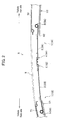
- a sunroof panel N which is opened or closed in response to the operation of passengers is provided above the sunshade devices 1A, 1B as shown in Fig. 2 .
- the sunroof panel N is adapted to be tilted up or tilted down to be moved in the front-rear direction of the vehicle.
- a symbol T1 represents a front garnish and a symbol T2 represents a fixed panel.
- Symbols U1, U2 represent roof linings.
- sunshade devices 1A, 1B are substantially the same structure except their arranged direction, only the sunshade device 1A arranged on the rear side of the vehicle is described as an example.
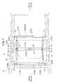
- the sunshade device 1(1A) includes a pair of shade guide rails 2 arranged on opposite sides of the indoor opening R2 in a vehicle width direction, a shade 3 which covers the upper side of the indoor opening R2; a handle 4 which is provided on the leading end of the shade 3; a winding shaft 5 which delivers or winds the shade 3; and multi functional stoppers 6 which are attached to ends of the pair of the shade guide rails 2.
- the shade guide rail 2 is an aluminum alloy extruded member and guides the shade 3 in the front-rear direction.
- the shade guide rail 2 is formed longer than the length of the indoor opening R2 in the front-rear direction.
- the opposed shade guide rails 2, 2 are arranged in parallel.
- the shade guide rail 2 includes a bottom plate portion 11, an outer wall portion 12, a middle plate portion 13, an inner wall portion 14 and an upper plate portion 15.
- the bottom plate portion 11 includes a first bottom plate portion 16, a second bottom plate portion 17 and a third bottom plate portion 18.
- the third bottom plate portion 18 is arranged between the first bottom plate portion 16 and the second bottom plate portion 17 and is formed a step upper than the first bottom plate portion 16 and the second bottom plate portion 17.
- a rib portion 16a is formed at the vehicle inner side end of the first bottom plate portion 16.
- the outer wall portion 12 is vertically erected on the second bottom plate portion 17.
- the middle plate portion 13 extends from the outer wall portion 12 toward the vehicle inner side and is perpendicular to the outer wall portion 12.
- a rib portion 13a Provided at the inner side end of the middle plate portion 13a is a rib portion 13a extending in the front-rear direction of the vehicle and protruded downward from the inner side end of the middle plate portion 13a.
- the inner wall portion 14 is vertically erected on a vehicle inner side part of the middle plate portion 13.
- the height position of the upper end of the inner wall portion 14 is substantially the same as that of the upper end of the outer wall portion 12.
- the upper plate portion 15 extends toward the vehicle inner side from the upper end of the inner wall portion 14 and is perpendicular to the inner wall portion 14.
- the third bottom plate portion 18, the outer wall portion 12 and the middle plate portion 13 constitute a groove portion 21.
- the groove portion 21 is a part in which a fold part 32 formed by folding the side edge of the shade 3 is inserted.
- the first bottom plate portion 16, the upper plate portion 15 and the inner wall portion 14 constitute a sliding part 22.
- the sliding part 22 is a part along which a slide shoe 41 described later is slid.
- the middle plate portion 13, the outer wall portion 12 and the inner wall portion 14 constitute an engaging groove 23.
- the engaging groove 23 is a part with which a third engaging portion 62c (described later) is engaged.
- the rib portion 13a is a protrusion for preventing the fold part 32 of the shade 3 from being removed toward the vehicle inner side.
- the rib portion 13a extends vertically downward at the vehicle inner side relative to the fold part 32 of the shade 3 as shown in Fig. 3 .
- the height of the groove portion 21 on the vehicle inner side becomes smaller, whereby the shade 3 is prevented from being removed in the vehicle inner side.
- the rib portion may be adapted to vertically extend upward from the bottom plate portion 11.
- the shade 3 is a thin screen and is comprised of a member which shades light.
- the shade 3 is formed in a width larger than that of the indoor opening R2 as shown in Fig. 1 .
- the handle 4 is provided at the leading end of the shade 3.
- a base end of the shade 3 is fixed to the winding shaft 5 and is wound like a roll around the winding shaft 5.
- the shade 3 includes at the opposite side edges of the shade 3 folded introduction parts 31 each of which is formed by folding back the side edge portion 3a.
- the folded introduction part 31 is formed such that the side edge portion 3a of the shade 3 is folded back in the width of 5mm to 2cm, for example, and the fold part of the side edge portion 3a is sewn to a main body 3b.
- the side edge portion 3a and the main body 3b can be connected solidly by sewing the side edge portion 3a and the main body 3b, the durability of the folded introduction part 31 can be enhanced.
- Dashed line indicated by the symbol St represents stitches.
- the folded introduction part 31 is formed in parallel to the front-rear direction axis from the leading end of the shade 3 in the opening and closing direction of the shade 3 (the front-rear direction in the embodiment).
- the length of the seam allowance is not limited to be a particular length, however, it is preferable to be in a range of 3cm to 15cm.
- a supporting bracket 42 is shown in alternate long and two short dashes lines for the purpose of the explanation.
- a fold line 3c is formed in parallel with the side edge portion 3a on the side portion of the main body 3b.
- the fold line 3c is a folding trace which is formed by folding the side edge portion 3a.
- the side edge portion 3a of the shade 3 and the main body 3b are sewn in the embodiment, however, the connection method is not limited to this.
- the side edge portion 3a and the main body 3b may be connected (bonded) with a stapler, an adhesive agent or a double faced tape or the like.
- the handle 4 is a resin member which is attached to the leading end side of the shade 3 and is a part used as a handle when the shade 3 is opened or closed.
- the handle 4 extends in parallel with the width direction axis of the shade 3.
- the handle 4A of the sunshade device 1A and the handle 4B of the sunshade device 1B come in contact with each other when the shade is closed completely.
- the part shown in dashed lines in Fig. 2 indicates the positions of the handle 4A and 4B when the shade 3 is completely opened.
- the handle 4 includes a base 40 which extends in the width direction; slide shoes 41 which are provided at opposite side ends of the base 40; and supporting brackets 42 which are adjacent to the slide shoes 41 at opposite side ends of the base 40 as shown in Figs. 1 and 3 .
- the slide shoe 41 is slid in the sliding part 22 in the vehicle front-rear direction (opening and closing direction) by force applied to the handle 4.
- the slide shoe 41 may be any shape as long as the slide shoe 41 can be stably slid in the sliding part 22.
- the slide shoe 41 is slid in the sliding part 22 in the embodiment, however, the slide shoe 41 may be slid in the groove portion 21.
- the supporting bracket 42 is protruded from the base 40 toward the vehicle outer side at the rear side of the vehicle relative to the slide shoe 41 (on a shade opening side) as shown in Figs. 1 and 3 .
- the supporting bracket 42 functions as "a contact portion" (see Fig. 11 ) which comes in contact with the multi functional stopper 6 when the shade 3 is completely opened in the embodiment.
- the supporting bracket 42 moves integrally with the base 40 above the shade guide rail 2.
- the supporting bracket 42 is a member supporting a drum which is a part of a holding mechanism for holding the shade 3 at an arbitrary opening position. Description on the holding mechanism for holding the shade 3 at an arbitrary opening position is omitted since the holding mechanism is not within a spirit of the present invention.
- the winding shaft 5 is a member for winding the shade 3 like a roll and is provided in parallel with the width direction axis of the shade 3 as shown in Figs. 1 and 2 .
- the opposite ends of the winding shaft 5 in its width direction are rotatably supported by the fixed roof R1 via holders 51.
- the multi functional stopper 6 is a member which restricts the movement of the shade 3 when the shade 3 is completely opened and guides the folding of the side edge of the shade 3.
- the multi functional stopper 6 is formed, for example, of a resin mold.
- the multi functional stopper 6 is attached to the rear end of the shade guide rail 2 (the end of the shade guide rail 2 on the opening side of the shade) as shown in Fig. 5 . More specifically, as shown in Fig. 1 , the multi functional stoppers 6A, 6A according to the sunshade device 1A are attached to the rear ends of the shade guide rails 2 (the ends of the shade guide rails 2 on the opening side of the shade 3A), respectively.
- the multi functional stoppers 6B, 6B in the sunshade device 1B are attached to the front ends of the shade guide rails 2 (the ends of the shade guide rails 2 on the opening side of the shade 3B).
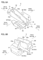
- the multi functional stopper 6 is mainly comprised of a base body portion 61 whose cross sectional shape is a substantially laid U shape; three engaging portions 62 protruding from the base body portion 61; and a restriction portion 63 formed on the base body portion 61 as shown in Figs. 6A and 6B .
- the base body portion 61 includes: a bottom portion 65; an erected wall portion 66 erecting vertically from the vehicle outside portion of the bottom portion 65; and a center portion 67 extending toward the vehicle inner side from the erected wall portion 66.
- the bottom portion 65 includes a pair of first introduction wall portions 68 formed in the vehicle inner side portion of the bottom portion 65 and a pair of second introduction wall portions 69 formed in the vehicle outer side portion of the bottom portion 65 as shown in Figs. 6A and 6B .
- the first introduction wall portion 68 and the second introduction wall portion 69 erect vertically on the bottom portion 65 and are arranged in parallel with each other in the width direction of multi functional stopper 6 with some space therebetween.
- the upper part of the first introduction wall portion 68 is opened, and the upper part of the second introduction wall portion 69 is covered by the center portion 67.
- the first introduction wall portion 68 is formed to be a little higher than the second introduction wall portion 69.
- the first introduction wall portion 68 and the second introduction wall portion 69 extend in the vehicle front-rear direction (the opening and closing direction of the shade 3), and the height of the first introduction wall portion 68 and the second introduction wall portion 69 is gradually lowered toward the vehicle rear side. More specifically, the upper ends of the first introduction wall portion 68 and the second introduction wall portion 69 are formed in a curved surface (inclined surface) protruding upward.
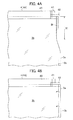
- the height H1 from the second introduction wall portion 69 to the center portion 67 at the rear end of the second introduction wall portion 69 is made greater than the height H2 from the second introduction wall portion 69 to the center portion 67 at the front end of the second introduction wall portion 69 (the end of the second introduction wall portion 69 on the closing side of the shade 3) as shown in Fig. 7B .
- the height H2 is made smaller than the height H3 of the groove portion 21 of the shade guide rail 2.
- the erected wall portion 66 is a portion which is erected on the end of the bottom portion 65 on the vehicle outer side as shown in Fig. 6A .
- the center portion 67 is perpendicular to the erected wall portion 66 and extends toward the vehicle inner side from the inner surface of the erected wall portion 66.
- the base body portion 61 is formed in a substantially laid U shape in a cross section, and the hollow part of the base body portion 61 functions as a folding guide groove 70 which folds the side edge of the shade 3.
- the engaging portion 62 includes a first engaging portion 62a, a second engaging portion 62b and a third engaging portion 62c in the embodiment as shown in Figs. 6A and 6B .
- the engaging portion 62 is a part which is engaged with the rear end of the shade guide rail 2 (the end of the shade guide rail 2 on the opening side of the shade 3).
- the first engaging portion 62a is a plate member protruding toward the vehicle front side from the vehicle inner side portion of the bottom portion 65.
- the first engaging portion 62a becomes narrower toward its distal end.
- the second engaging portion 62b is a plate member protruding toward the vehicle outer side and the vehicle front side from the outer side surface of the erected wall portion 66.
- the third engaging portion 62c is a plate member protruding toward the vehicle front side from the center portion 67.
- the third engaging portion 62c becomes narrower toward its distal end.
- Formed on the lower surface of the third engaging portion 62c is an engaging protrusion 72 (see Fig. 7A ) protruding downward.
- the restriction portion 63 is a portion for regulating the movement of the shade 3 at the completely-opened position of the shade 3 as shown in Figs. 6A and 6B .
- the restriction portion 63 includes: a pair of side wall portions 63a, 63b erected on the center portion 67; a front face portion 63c which connects the front ends of the side wall portions 63a, 63b; and a horizontal rib 63d which connects the side wall portion 63b and the center portion 67.
- a circular hole is formed on the front face portion 63c, and a buffer member 71 is fit into the circular hole.
- the buffer member 71 is a member which buffers an impact applied when the supporting bracket(contact portion)42 comes in contact with the multi functional stopper 6 when the shade 3 is completely opened.
- the buffer member 71 is formed, for example, of rubber.
- the buffer member 71 may be provided as necessary.
- the slide shoe 41 is inserted into the sliding part 22 from the rear end of the shade guide rail 2 (the end of the shade guide rail 2 on the opening side of the shade 3) provided to the fixed roof R1 and only the folded introduction part 31 is inserted into the groove portion 21.
- the multi functional stopper 6 is engaged with the rear ends of the shade guide rail 2 as shown in Figs. 8A and 8B . It is to be noted that the shade 3 is omitted in Figs. 8A and 8B .
- the first engaging portion 62a is brought into contact with the lower surface of the first bottom plate portion 16 of the shade guide rail 2
- the second engaging portion 62b is brought into contact with the upper surface of the second bottom plate portion 17 and the side surface of the outer wall portion 12 of the shade guide rail 2
- the third engaging portion 62c is brought into contact with the middle plate portion 13 as shown in Figs. 8A and 8B .
- the third engaging portion 62c is fit into the engaging groove 23 whose bottom surface is the middle plate portion 13 and the engaging protrusion 72 (see Fig. 7A ) formed at the distal end of the third engaging portion 62c is engaged with a recessed portion 23a formed in the engaging groove 23.
- the folding guide groove 70 and the groove portion 21 of the shade guide rail 2 are communicated with each other when the multi functional stopper 6 is engaged with the shade guide rail 2.
- the upper end of the second introduction wall portion 69 is positioned above the upper surface of the groove portion 21.
- the lower surface of the center portion 67 is flushed with the lower surface of the middle plate portion 13. It is preferable that the upper end of the second introduction wall portion 69 is flushed with the upper surface of the groove portion 21 or is positioned above the upper surface of the groove portion 21. Further, it is preferable that the lower surface of the center portion 67 is flushed with the middle plate portion 13 or is positioned below the middle plate portion 13. More specifically, with the structure in which the end of the shade guide rail 2 is not exposed when the multi functional stopper 6 is engaged with the shade guide rail 2 it is possible to prevent the shade 3 from being caught by the end of the shade guide rail 2.
- the multi functional stopper 6 can be removed easily from the shade guide rail 2 by pulling the multi functional stopper 6 toward the vehicle rear side while removing the engaging protrusion 72 from the recessed portion 23a of the engaging groove 23.
- Fig. 9A is a schematic plain view showing the effect of the sunshade apparatus when the shade 3 is closed completely.
- Fig. 9B is a schematic plain view showing the effect of the sunshade apparatus when the shade 3 is opened completely.
- Fig. 9A when a passenger moves the handle 4 to the vehicle front side, the shade 3 is drawn out from the winding shaft 5 and the indoor opening R2 is covered by the shade 3.
- the side edge of the shade 3 is folded by the time when the side edge of the shade 3 is inserted into the shade guide rail 2 from the time when the shade 3 is started to be drawn out, and the shade 3 is moved in the shade guide rail 2 with the side edge of the shade 3 being folded.
- the side edge of the shade 3 is classified into 4 parts when the shade 3 is drawn out.
- the part indicated by the reference numeral 31 is a "folded introduction part" described before.
- the folded introduction part 31 is kept folded since the side edge portion 3a is sewn.
- the part indicated by the reference number 32 is a "fold part”.
- the fold part 32 is a part which gets folded by being inserted into the shade guide rail 2.
- the part indicated by the reference numeral 33 is “non-folded part” in which the side edge portion 3a is not folded immediately after the shade 3 is drawn out from the winding shaft 5.
- the part indicated by the reference numeral 32 is a "folding stroke”.
- the folding stroke 34 is a part formed between the non-folded part 33 and the fold part 32, and the width of the folded portion of the folding stroke 34 is gradually increased toward the leading end (the vehicle front side) of the shade 3.
- the shade 3 drawn out from the winding shaft 5 is guided by the shade guide rail 2 with its opposed edges being folded after the folding stroke 34 and opens or closes the indoor opening R2 in the vehicle front-rear direction.
- the part indicated by the reference symbol S in Figs. 9A and 9B is an "inclination changing space".
- the inclination changing space S inclined in a side view is formed on a path of the shade 3 immediately after the shade 3 is drawn out from the winding shaft 5 as shown in Fig. 10 .
- a drawing path of the shade 3 when most of the shade 3 is wound around the winding shaft 5 is indicated by a solid line and a drawing path of the shade 3 when only a little of the shade 3 is wound is indicated by a virtual line.
- the inclination changing space S is inevitably formed between the winding shaft 5 and the shade guide rail 2.
- the dimension of the inclination changing space S in the vehicle front-rear direction is shortened (i.e. if the space between the winding shaft 5 and the shade guide rail 2 is shortened)
- the inclination angle ⁇ of the shade 3 is made larger.
- the component in the vertical direction is also made larger. Therefore, the loss of the operational weight by the handle 4 (see Figs. 9A and 9B ) in the horizontal direction becomes larger, whereby larger manual operation force needs to be applied to the handle 4.
- the dimension of the inclination changing space S in the vehicle front-rear direction needs to be large enough.
- a dimension of the inclination changing space S in the vehicle front-rear direction needs to be more than that of the folding stroke 34.
- the fold line 3c is formed along the opposite sides of the main body 3b of the shade 3, the fold line 3 can be instrumental in folding the opposite sides of the main body 3b, and the shade 3 can be folded in a desired position.
- the folding guide groove 70 is communicated with the groove portion 21 of the shade guide rail 2 and the height H1 of the opening provided at the end of the folding guide groove 70 on the rear side of the shade 3 (on the opening side of the shade 3) is adapted to be larger than the height 3 of the groove portion 21.
- the shade 3 whose side edge is folded is guided by the folding guide groove 70 and is smoothly inserted into the shade guide rail 2.
- the folded width of the fold part 32 of the shade 3 can be made constant.
- the height H2 of the opening provided at the end of the folding guide groove 70 on the front end side of the shade 3 (on the closing side of the shade 3) is adapted to be smaller than the height 3 of the groove portion 21 and the end of the shade guide rail 2 is not exposed.
- first introduction wall portion 68 and the second introduction wall portion 69 of the multi functional stopper 6 are formed to be gradually lowered toward the vehicle rear side (on the opening side of the shade) as shown in Fig. 10 , which makes it easy to guide the shade 3. More specifically, although the inclination angle of the shade 3 in a side view is varied depending on the length of the shade 3 wound around the winding shaft 5, the shade 3 can be smoothly guided because the upper faces of the first introduction wall portion 68 and the second introduction wall portion 69 are formed in a curved surface which is lowered toward the vehicle rear side (the opening direction of the shade). With this structure, the friction resistance between the shade 3 and the first introduction wall portion 68 and the second introduction wall portion 69 due to the variation in the inclination angle of the shade 3 can be reduced.
- the friction between the shade 3 and the first introduction wall portions 68 and the second introduction wall portions 69 can be made smaller, whereby the shade 3 can be prevented from being worn.
- the shade 3 can be easily restored by moving the handle 4 to the completely-opened position (i.e. the position where the supporting bracket 42 comes in contact with the buffer member 71 (the restriction portion 63)) of the multi functional stopper 6 once and then withdrawing the shade 3 again as shown in Fig. 11 .
- the twisted part of the shade 3 can be restored since the most part of the shade 3 is wound around the winding shaft 5 in the completely opened position.
- the shade 3 can be guided by the shade guide rail 2 again just by withdrawing the handle 4 from the completely-opened position since the folded introduction part 31 is positioned in the folding guide groove 70 at the completely-opened position.
- a pair of sunshade devices 1A, 1B is provided in the vehicle front-rear direction in the embodiment, however, either one of the sunshade devices 1A, 1B may be provided and made to cover an entire part of the indoor opening R2.
- the shade 3 is opened or closed in the vehicle front-rear direction in the embodiment, however, the shade may be opened or closed in the width direction of the vehicle.
- the supporting bracket 42 formed in the handle 4 is brought into contact with the restriction portion 63 in the embodiment, however, an embodiment of the present invention is not limited to this.
- an embodiment may be employed in which at least a part of the handle 4 and a part of the multi functional stopper 6 (a restriction part) come in contact with each other as long as the movement of the handle 4 is restricted.
- a part of the multi functional stopper 6 which faces to the sliding part 22 may be provided with a part for restricting the movement of the slide shoe 41 (restriction part) and the slide shoe 41 is brought in contact with the restriction part.
Landscapes
- Engineering & Computer Science (AREA)
- Mechanical Engineering (AREA)
- Operating, Guiding And Securing Of Roll- Type Closing Members (AREA)
Abstract
Description
- The present invention relates to a sunshade device which is provided to a fixed roof of a vehicle.
- A sunshade device has been known which takes in or shields sunlight from an indoor opening of a vehicle. For example, Unexamined Japanese Patent Application Publication No.
2010—36898 - The sunshade device disclosed in Unexamined Japanese Patent Application Publication No.
2010—36898 2010—36898 - In accordance with this technique, by folding the side edge of the shade the restoring force of the side edge of the shade to return to its original state is exerted continuously over the entire folded part. Therefore, even if a part of the side edge of the shade is likely to be removed from the shade guide rail, for example, by the external force applied to the shade, the restoring force exerted around the part of the shade likely to be removed acts to pull the side edge of the
shade 3 to return to theshade guide rail 2. Thus, the side edge of theshade 3 is difficult to be removed from theshade guide rail 2. - In the conventional shade device, however, there has been a problem that a work for assembling the shade to the shade guide rail is complicated because when the shade is assembled to the shade guide rail, the opposite side edges of the shade must be inserted into a pair of shade guide rails with the opposite side edges of the shade being kept folded after the opposite side edges of the front end of the shade are folded. Further, there has been another problem that if a part of the side edge of the shade is removed from the shade guide rail due to external force, a work for restoring the shade is complicated.
- The present invention has been made in view of the above problems, and an object of at least the preferred embodiments thereof is to provide a sunshade device in which the assembling work and the restoring work of the shade are easy.
- A first aspect of the present invention provides a sunshade device which is provided to a fixed roof of a vehicle, the sunshade device including: a pair of shade guide rails which is provided on opposite sides of the sunshade device across an indoor opening of the fixed roof; a shade of which opposite side edges are guided by the shade guide rails to open or close the indoor opening; and a winding shaft which rolls up the shade, wherein each of the opposite side edges of the shade is guided by the shade guide rail with the side edge being folded through a folding stroke whose folded width is gradually increased toward a leading end of the shade when the shade is drawn out from the winding shaft, the each of the opposite side edges of the shade is provided in advance with a folded introduction part that is formed by folding a side edge portion of the shade and connecting the folded side edge portion to a main body portion of the shade, and the folded introduction part is formed in a predetermined length from the leading end of the shade in an open/close direction of the shade.
- In the aforementioned sunshade device, it is preferable that a folded line for folding the side edge portion of the shade is formed on each opposite side of the main body portion of the shade, and the folded line is formed in the open/close direction of the shade.
- In the aforementioned sunshade device, it is preferable that the folded introduction part is formed by sewing the side edge portion of the shade and the main body portion of the shade together.
- In the aforementioned sunshade device, it is preferable that the shade guide rail includes a groove portion accommodating a folded portion which is formed by folding the shade and the groove portion includes a rib portion which extends in a vertical direction at a position inside of the vehicle relative to the folded portion.
- In the aforementioned sunshade device, it is preferable that the aforementioned sunshade device further includes: a handle which is attached to the leading end of the shade and includes slide shoes which are slid in the shade guide rails; and multifunctional stoppers which are provided at ends of the shade guide rails on an opening side of the shade, wherein each of the multifunctional stopper includes a restriction portion which comes in contact with the handle at a completely-opened position of the shade and a base body portion including a folding guide groove through which the folded side edge of the shade is inserted, the folding guide groove being communicated with a groove portion of the shade guide rail, and wherein a height of an opening of the folding guide groove on the opening side of the shade is larger than a height of the groove portion.
- In the aforementioned sunshade device, it is preferable that the main body portion includes a bottom portion which forms a lower portion of the folding guide groove, wherein the bottom portion being inclined downward toward the opening side of the shade.
- In the aforementioned sunshade device, it is preferable that the height of the opening of the folding guide groove on the closing side of the shade is smaller than the height of the groove portion.
-
-
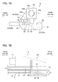
Fig. 1 is a schematic plain view showing a sunshade device according to an embodiment of the present invention. -
Fig. 2 is a side cross sectional view of the sunshade device shown inFig. 1 . -
Fig. 3 is a cross sectional view of the sunshade device along the line I-I inFig. 1 . -
Fig. 4A is a plain view showing a leading end of the shade and a part around the leading end after the leading end is folded. -
Fig. 4B is a plain view showing a leading end of the shade and a part around the leading end before the leading end is folded. -
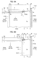
Fig. 5 is a perspective view showing a multifunctional stopper which is mounted on a shade guide rail. -
Fig. 6A is a perspective view showing the multifunctional stopper seen from the vehicle rear side. -
Fig. 6B is a perspective view showing the multifunctional stopper seen from the vehicle front side. -
Fig. 7A is a front view of the multifunctional stopper. -
Fig. 7B is a side cross sectional view of the multifunctional stopper. -
Fig. 8A is a perspective view showing how the multifunctional stopper is assembled to the shade guide rail. -
Fig. 8B is a cross sectional view showing the multifunctional stopper which has been assembled to the shade guide rail. -
Fig. 9A is a schematic plain view showing the effect of the sunshade device in which the shade is closed completely. -
Fig. 9B is a schematic plain view showing the effect of the sunshade device in which the shade is opened completely. -
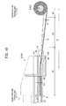
Fig. 10 is a side cross sectional view of the sunshade device showing the effect of the sunshade device. -
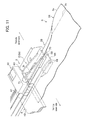
Fig. 11 is a perspective view of the sunshade device showing the effect of the sunshade device. - An embodiment of the present invention is described in detail below with reference to the accompanying drawings, by way of example only. As shown in
Figs. 1 and2 , asunshade device 1 according to the embodiment is a device which is provided to a fixed roof R1 of a vehicle R for taking in or shading light coming through an indoor opening R2. - A vehicle R according to the embodiment includes a
sunshade device 1A which is provided on the rear side of the vehicle R and asunshade device 1B which is provided on the front side of the vehicle R. Thesunshade devices shade guide rail 2 and are arranged substantially symmetrical in the vehicle front-rear direction. Thesunshade devices - A sunroof panel N which is opened or closed in response to the operation of passengers is provided above the
sunshade devices Fig. 2 . The sunroof panel N is adapted to be tilted up or tilted down to be moved in the front-rear direction of the vehicle. A symbol T1 represents a front garnish and a symbol T2 represents a fixed panel. Symbols U1, U2 represent roof linings. - Since the
sunshade devices sunshade device 1A arranged on the rear side of the vehicle is described as an example. - As shown in
Fig. 1 , the sunshade device 1(1A) includes a pair ofshade guide rails 2 arranged on opposite sides of the indoor opening R2 in a vehicle width direction, ashade 3 which covers the upper side of the indoor opening R2; ahandle 4 which is provided on the leading end of theshade 3; awinding shaft 5 which delivers or winds theshade 3; and multifunctional stoppers 6 which are attached to ends of the pair of theshade guide rails 2. - The
shade guide rail 2 is an aluminum alloy extruded member and guides theshade 3 in the front-rear direction. Theshade guide rail 2 is formed longer than the length of the indoor opening R2 in the front-rear direction. The opposedshade guide rails - As shown in
Fig. 3 , theshade guide rail 2 includes abottom plate portion 11, anouter wall portion 12, amiddle plate portion 13, aninner wall portion 14 and anupper plate portion 15. Thebottom plate portion 11 includes a firstbottom plate portion 16, a secondbottom plate portion 17 and a thirdbottom plate portion 18. The thirdbottom plate portion 18 is arranged between the firstbottom plate portion 16 and the secondbottom plate portion 17 and is formed a step upper than the firstbottom plate portion 16 and the secondbottom plate portion 17. Arib portion 16a is formed at the vehicle inner side end of the firstbottom plate portion 16. - The
outer wall portion 12 is vertically erected on the secondbottom plate portion 17. Themiddle plate portion 13 extends from theouter wall portion 12 toward the vehicle inner side and is perpendicular to theouter wall portion 12. Provided at the inner side end of themiddle plate portion 13a is arib portion 13a extending in the front-rear direction of the vehicle and protruded downward from the inner side end of themiddle plate portion 13a. - The
inner wall portion 14 is vertically erected on a vehicle inner side part of themiddle plate portion 13. The height position of the upper end of theinner wall portion 14 is substantially the same as that of the upper end of theouter wall portion 12. Theupper plate portion 15 extends toward the vehicle inner side from the upper end of theinner wall portion 14 and is perpendicular to theinner wall portion 14. - The third
bottom plate portion 18, theouter wall portion 12 and themiddle plate portion 13 constitute agroove portion 21. Thegroove portion 21 is a part in which afold part 32 formed by folding the side edge of theshade 3 is inserted. The firstbottom plate portion 16, theupper plate portion 15 and theinner wall portion 14 constitute a slidingpart 22. The slidingpart 22 is a part along which aslide shoe 41 described later is slid. Further, themiddle plate portion 13, theouter wall portion 12 and theinner wall portion 14 constitute an engaginggroove 23. The engaginggroove 23 is a part with which a thirdengaging portion 62c (described later) is engaged. Therib portion 13a is a protrusion for preventing thefold part 32 of theshade 3 from being removed toward the vehicle inner side. - The
rib portion 13a extends vertically downward at the vehicle inner side relative to thefold part 32 of theshade 3 as shown inFig. 3 . Thus, the height of thegroove portion 21 on the vehicle inner side becomes smaller, whereby theshade 3 is prevented from being removed in the vehicle inner side. If theside edge portion 3a is configured to be folded downward, the rib portion may be adapted to vertically extend upward from thebottom plate portion 11. - The
shade 3 is a thin screen and is comprised of a member which shades light. Theshade 3 is formed in a width larger than that of the indoor opening R2 as shown inFig. 1 . Thehandle 4 is provided at the leading end of theshade 3. A base end of theshade 3 is fixed to the windingshaft 5 and is wound like a roll around the windingshaft 5. - As shown in
Fig. 4A , theshade 3 includes at the opposite side edges of theshade 3 foldedintroduction parts 31 each of which is formed by folding back theside edge portion 3a. As shown inFig. 4B , the foldedintroduction part 31 is formed such that theside edge portion 3a of theshade 3 is folded back in the width of 5mm to 2cm, for example, and the fold part of theside edge portion 3a is sewn to amain body 3b. As theside edge portion 3a and themain body 3b can be connected solidly by sewing theside edge portion 3a and themain body 3b, the durability of the foldedintroduction part 31 can be enhanced. - Dashed line indicated by the symbol St represents stitches. The folded
introduction part 31 is formed in parallel to the front-rear direction axis from the leading end of theshade 3 in the opening and closing direction of the shade 3 (the front-rear direction in the embodiment). The length of the seam allowance is not limited to be a particular length, however, it is preferable to be in a range of 3cm to 15cm. InFigs. 4A and 4B , a supportingbracket 42 is shown in alternate long and two short dashes lines for the purpose of the explanation. - A
fold line 3c is formed in parallel with theside edge portion 3a on the side portion of themain body 3b. Thefold line 3c is a folding trace which is formed by folding theside edge portion 3a. By forming thefold line 3c in advance, the folding width of theside edge portion 3a can be made constant when theshade 3 is inserted into theshade guide rail 2. - The
side edge portion 3a of theshade 3 and themain body 3b are sewn in the embodiment, however, the connection method is not limited to this. For example, theside edge portion 3a and themain body 3b may be connected (bonded) with a stapler, an adhesive agent or a double faced tape or the like. - The
handle 4 is a resin member which is attached to the leading end side of theshade 3 and is a part used as a handle when theshade 3 is opened or closed. Thehandle 4 extends in parallel with the width direction axis of theshade 3. As shown inFig. 2 , thehandle 4A of thesunshade device 1A and thehandle 4B of thesunshade device 1B come in contact with each other when the shade is closed completely. The part shown in dashed lines inFig. 2 indicates the positions of thehandle shade 3 is completely opened. - The
handle 4 includes a base 40 which extends in the width direction; slideshoes 41 which are provided at opposite side ends of thebase 40; and supportingbrackets 42 which are adjacent to the slide shoes 41 at opposite side ends of the base 40 as shown inFigs. 1 and3 . - The
slide shoe 41 is slid in the slidingpart 22 in the vehicle front-rear direction (opening and closing direction) by force applied to thehandle 4. Theslide shoe 41 may be any shape as long as theslide shoe 41 can be stably slid in the slidingpart 22. Theslide shoe 41 is slid in the slidingpart 22 in the embodiment, however, theslide shoe 41 may be slid in thegroove portion 21. - The supporting
bracket 42 is protruded from the base 40 toward the vehicle outer side at the rear side of the vehicle relative to the slide shoe 41 (on a shade opening side) as shown inFigs. 1 and3 . The supportingbracket 42 functions as "a contact portion" (seeFig. 11 ) which comes in contact with the multifunctional stopper 6 when theshade 3 is completely opened in the embodiment. The supportingbracket 42 moves integrally with thebase 40 above theshade guide rail 2. The supportingbracket 42 is a member supporting a drum which is a part of a holding mechanism for holding theshade 3 at an arbitrary opening position. Description on the holding mechanism for holding theshade 3 at an arbitrary opening position is omitted since the holding mechanism is not within a spirit of the present invention. - The winding
shaft 5 is a member for winding theshade 3 like a roll and is provided in parallel with the width direction axis of theshade 3 as shown inFigs. 1 and2 . The opposite ends of the windingshaft 5 in its width direction are rotatably supported by the fixed roof R1 viaholders 51. - The multi
functional stopper 6 is a member which restricts the movement of theshade 3 when theshade 3 is completely opened and guides the folding of the side edge of theshade 3. The multifunctional stopper 6 is formed, for example, of a resin mold. The multifunctional stopper 6 is attached to the rear end of the shade guide rail 2 (the end of theshade guide rail 2 on the opening side of the shade) as shown inFig. 5 . More specifically, as shown inFig. 1 , the multifunctional stoppers sunshade device 1A are attached to the rear ends of the shade guide rails 2 (the ends of theshade guide rails 2 on the opening side of theshade 3A), respectively. The multifunctional stoppers sunshade device 1B are attached to the front ends of the shade guide rails 2 (the ends of theshade guide rails 2 on the opening side of theshade 3B). - The multi
functional stopper 6 is mainly comprised of abase body portion 61 whose cross sectional shape is a substantially laid U shape; three engagingportions 62 protruding from thebase body portion 61; and arestriction portion 63 formed on thebase body portion 61 as shown inFigs. 6A and 6B . - The
base body portion 61 includes: abottom portion 65; an erectedwall portion 66 erecting vertically from the vehicle outside portion of thebottom portion 65; and acenter portion 67 extending toward the vehicle inner side from the erectedwall portion 66. - The
bottom portion 65 includes a pair of firstintroduction wall portions 68 formed in the vehicle inner side portion of thebottom portion 65 and a pair of secondintroduction wall portions 69 formed in the vehicle outer side portion of thebottom portion 65 as shown inFigs. 6A and 6B . The firstintroduction wall portion 68 and the secondintroduction wall portion 69 erect vertically on thebottom portion 65 and are arranged in parallel with each other in the width direction of multifunctional stopper 6 with some space therebetween. As shown inFig. 7A , the upper part of the firstintroduction wall portion 68 is opened, and the upper part of the secondintroduction wall portion 69 is covered by thecenter portion 67. The firstintroduction wall portion 68 is formed to be a little higher than the secondintroduction wall portion 69. - The first
introduction wall portion 68 and the secondintroduction wall portion 69 extend in the vehicle front-rear direction (the opening and closing direction of the shade 3), and the height of the firstintroduction wall portion 68 and the secondintroduction wall portion 69 is gradually lowered toward the vehicle rear side. More specifically, the upper ends of the firstintroduction wall portion 68 and the secondintroduction wall portion 69 are formed in a curved surface (inclined surface) protruding upward. With this structure, the height H1 from the secondintroduction wall portion 69 to thecenter portion 67 at the rear end of the second introduction wall portion 69 (the end of the secondintroduction wall portion 69 on the opening side of the shade 3) is made greater than the height H2 from the secondintroduction wall portion 69 to thecenter portion 67 at the front end of the second introduction wall portion 69 (the end of the secondintroduction wall portion 69 on the closing side of the shade 3) as shown inFig. 7B . It is to be noted that the height H2 is made smaller than the height H3 of thegroove portion 21 of theshade guide rail 2. - The erected
wall portion 66 is a portion which is erected on the end of thebottom portion 65 on the vehicle outer side as shown inFig. 6A . Thecenter portion 67 is perpendicular to the erectedwall portion 66 and extends toward the vehicle inner side from the inner surface of the erectedwall portion 66. With this structure, thebase body portion 61 is formed in a substantially laid U shape in a cross section, and the hollow part of thebase body portion 61 functions as afolding guide groove 70 which folds the side edge of theshade 3. - The engaging
portion 62 includes a firstengaging portion 62a, a secondengaging portion 62b and a thirdengaging portion 62c in the embodiment as shown inFigs. 6A and 6B . The engagingportion 62 is a part which is engaged with the rear end of the shade guide rail 2 (the end of theshade guide rail 2 on the opening side of the shade 3). - The first
engaging portion 62a is a plate member protruding toward the vehicle front side from the vehicle inner side portion of thebottom portion 65. The firstengaging portion 62a becomes narrower toward its distal end. - The second
engaging portion 62b is a plate member protruding toward the vehicle outer side and the vehicle front side from the outer side surface of the erectedwall portion 66. The thirdengaging portion 62c is a plate member protruding toward the vehicle front side from thecenter portion 67. The thirdengaging portion 62c becomes narrower toward its distal end. Formed on the lower surface of the third engagingportion 62c is an engaging protrusion 72 (seeFig. 7A ) protruding downward. - The
restriction portion 63 is a portion for regulating the movement of theshade 3 at the completely-opened position of theshade 3 as shown inFigs. 6A and 6B . Therestriction portion 63 includes: a pair ofside wall portions center portion 67; afront face portion 63c which connects the front ends of theside wall portions horizontal rib 63d which connects theside wall portion 63b and thecenter portion 67. - In the embodiment, a circular hole is formed on the
front face portion 63c, and abuffer member 71 is fit into the circular hole. Thebuffer member 71 is a member which buffers an impact applied when the supporting bracket(contact portion)42 comes in contact with the multifunctional stopper 6 when theshade 3 is completely opened. Thebuffer member 71 is formed, for example, of rubber. Thebuffer member 71 may be provided as necessary. - Next, a method for assembling the
sunshade device 1 is described. After the foldedintroduction part 31 is formed in theshade 3 as shown inFigs. 4A and 4B , theslide shoe 41 is inserted into the slidingpart 22 from the rear end of the shade guide rail 2 (the end of theshade guide rail 2 on the opening side of the shade 3) provided to the fixed roof R1 and only the foldedintroduction part 31 is inserted into thegroove portion 21. In this state, the multifunctional stopper 6 is engaged with the rear ends of theshade guide rail 2 as shown inFigs. 8A and 8B . It is to be noted that theshade 3 is omitted inFigs. 8A and 8B . - More specifically, the first engaging
portion 62a is brought into contact with the lower surface of the firstbottom plate portion 16 of theshade guide rail 2, the secondengaging portion 62b is brought into contact with the upper surface of the secondbottom plate portion 17 and the side surface of theouter wall portion 12 of theshade guide rail 2, and the third engagingportion 62c is brought into contact with themiddle plate portion 13 as shown inFigs. 8A and 8B . The thirdengaging portion 62c is fit into the engaginggroove 23 whose bottom surface is themiddle plate portion 13 and the engaging protrusion 72 (seeFig. 7A ) formed at the distal end of the third engagingportion 62c is engaged with a recessedportion 23a formed in the engaginggroove 23. With this structure, the position of the multifunctional stopper 6 is determined. Further, the lower surface of therestriction portion 63 comes in contact with the upper surface of theupper plate portion 15. Thus, the multifunctional stopper 6 is assembled in theshade guide rail 2. - As shown in
Fig. 7B , thefolding guide groove 70 and thegroove portion 21 of theshade guide rail 2 are communicated with each other when the multifunctional stopper 6 is engaged with theshade guide rail 2. The upper end of the secondintroduction wall portion 69 is positioned above the upper surface of thegroove portion 21. The lower surface of thecenter portion 67 is flushed with the lower surface of themiddle plate portion 13. It is preferable that the upper end of the secondintroduction wall portion 69 is flushed with the upper surface of thegroove portion 21 or is positioned above the upper surface of thegroove portion 21. Further, it is preferable that the lower surface of thecenter portion 67 is flushed with themiddle plate portion 13 or is positioned below themiddle plate portion 13. More specifically, with the structure in which the end of theshade guide rail 2 is not exposed when the multifunctional stopper 6 is engaged with theshade guide rail 2 it is possible to prevent theshade 3 from being caught by the end of theshade guide rail 2. - Further, the multi
functional stopper 6 can be removed easily from theshade guide rail 2 by pulling the multifunctional stopper 6 toward the vehicle rear side while removing the engagingprotrusion 72 from the recessedportion 23a of the engaginggroove 23. - Next, the effect of the
sunshade device 1 is described below.Fig. 9A is a schematic plain view showing the effect of the sunshade apparatus when theshade 3 is closed completely.Fig. 9B is a schematic plain view showing the effect of the sunshade apparatus when theshade 3 is opened completely. As shown inFig. 9A , when a passenger moves thehandle 4 to the vehicle front side, theshade 3 is drawn out from the windingshaft 5 and the indoor opening R2 is covered by theshade 3. The side edge of theshade 3 is folded by the time when the side edge of theshade 3 is inserted into theshade guide rail 2 from the time when theshade 3 is started to be drawn out, and theshade 3 is moved in theshade guide rail 2 with the side edge of theshade 3 being folded. - As shown in
Fig. 9A , the side edge of theshade 3 is classified into 4 parts when theshade 3 is drawn out. The part indicated by thereference numeral 31 is a "folded introduction part" described before. The foldedintroduction part 31 is kept folded since theside edge portion 3a is sewn. The part indicated by thereference number 32 is a "fold part". Thefold part 32 is a part which gets folded by being inserted into theshade guide rail 2. - The part indicated by the
reference numeral 33 is "non-folded part" in which theside edge portion 3a is not folded immediately after theshade 3 is drawn out from the windingshaft 5. The part indicated by thereference numeral 32 is a "folding stroke". Thefolding stroke 34 is a part formed between thenon-folded part 33 and thefold part 32, and the width of the folded portion of thefolding stroke 34 is gradually increased toward the leading end (the vehicle front side) of theshade 3. - As described in the embodiment, the
shade 3 drawn out from the windingshaft 5 is guided by theshade guide rail 2 with its opposed edges being folded after thefolding stroke 34 and opens or closes the indoor opening R2 in the vehicle front-rear direction. - By forming the
fold part 32 which is folded upward as shown inFig. 3 , restoring force of the side edge of theshade 3 to return to its original state is exerted continuously over theentire fold part 32. Therefore, even if a part of the side edge of theshade 3 is likely to be removed from theshade guide rail 2 by the external force applied to theshade 3 from the vehicle inner side, for example, the restoring force exerted around the part of the shade likely to be removed acts to pull the side edge of theshade 3 to return to theshade guide rail 2. Thus, the side edge of theshade 3 is difficult to be removed from theshade guide rail 2. - When a passenger moves the
handle 4 toward the vehicle rear side, theshade 3 is wound around the windingshaft 5 and the indoor opening R2 is opened as shown inFig. 9B . The position where the supporting bracket (contact portion) 42 of thehandle 4 is in contact with thebuffer member 71 of the multifunctional stopper 6 is the completely-opened position of theshade 3. - Here, the part indicated by the reference symbol S in
Figs. 9A and 9B is an "inclination changing space". In a structure where theshade 3 is wound around the windingshaft 5 like a roll, the inclination changing space S inclined in a side view is formed on a path of theshade 3 immediately after theshade 3 is drawn out from the windingshaft 5 as shown inFig. 10 . InFig. 10 , a drawing path of theshade 3 when most of theshade 3 is wound around the windingshaft 5 is indicated by a solid line and a drawing path of theshade 3 when only a little of theshade 3 is wound is indicated by a virtual line. - As described above, the inclination changing space S is inevitably formed between the winding
shaft 5 and theshade guide rail 2. However, if the dimension of the inclination changing space S in the vehicle front-rear direction is shortened (i.e. if the space between the windingshaft 5 and theshade guide rail 2 is shortened), the inclination angle θ of theshade 3 is made larger. If the inclination angle θ is made larger, the component in the vertical direction is also made larger. Therefore, the loss of the operational weight by the handle 4 (seeFigs. 9A and 9B ) in the horizontal direction becomes larger, whereby larger manual operation force needs to be applied to thehandle 4. Thus, the dimension of the inclination changing space S in the vehicle front-rear direction needs to be large enough. In a case of the embodiment in which thefolding stroke 34 is formed, a dimension of the inclination changing space S in the vehicle front-rear direction needs to be more than that of thefolding stroke 34. - In accordance with the
sunshade device 1 according to the embodiment described above, a process of folding theside edge portion 3a of the leading end of theshade 3 can be omitted when the leading end of theshade 3 is inserted into theshade guide rail 2 since the foldedintroduction part 31 is formed along the opposite edges of theshade 3 in advance. As a result, it is possible to easily assemble or restore theshade 3 to theshade guide rail 2. - Furthermore, since the
fold line 3c is formed along the opposite sides of themain body 3b of theshade 3, thefold line 3 can be instrumental in folding the opposite sides of themain body 3b, and theshade 3 can be folded in a desired position. - Further, in the embodiment, as the supporting
bracket 42 comes in contact with the buffer member 71 (the restriction portion 63) of the multifunctional stopper 6, the movement of theshade 3 can be restricted by the completely opened position of theshade 3. As shown inFig. 10 , thefolding guide groove 70 is communicated with thegroove portion 21 of theshade guide rail 2 and the height H1 of the opening provided at the end of thefolding guide groove 70 on the rear side of the shade 3 (on the opening side of the shade 3) is adapted to be larger than theheight 3 of thegroove portion 21. Thus, theshade 3 whose side edge is folded is guided by thefolding guide groove 70 and is smoothly inserted into theshade guide rail 2. With this structure, the folded width of thefold part 32 of theshade 3 can be made constant. - The height H2 of the opening provided at the end of the
folding guide groove 70 on the front end side of the shade 3 (on the closing side of the shade 3) is adapted to be smaller than theheight 3 of thegroove portion 21 and the end of theshade guide rail 2 is not exposed. With this structure, theshade 3 can be prevented from being damaged due to the contact between theshade 3 and the end of theshade guide rail 2 since theshade 3 does not come into contact with the end of theshade guide rail 2. - Further, the first
introduction wall portion 68 and the secondintroduction wall portion 69 of the multifunctional stopper 6 are formed to be gradually lowered toward the vehicle rear side (on the opening side of the shade) as shown inFig. 10 , which makes it easy to guide theshade 3. More specifically, although the inclination angle of theshade 3 in a side view is varied depending on the length of theshade 3 wound around the windingshaft 5, theshade 3 can be smoothly guided because the upper faces of the firstintroduction wall portion 68 and the secondintroduction wall portion 69 are formed in a curved surface which is lowered toward the vehicle rear side (the opening direction of the shade). With this structure, the friction resistance between theshade 3 and the firstintroduction wall portion 68 and the secondintroduction wall portion 69 due to the variation in the inclination angle of theshade 3 can be reduced. - Further, by erecting the plurality of the first
introduction wall portions 68 and the secondintroduction wall portions 69 of the multifunctional stopper 6 with some space being provided therebetween in the width direction, the friction between theshade 3 and the firstintroduction wall portions 68 and the secondintroduction wall portions 69 can be made smaller, whereby theshade 3 can be prevented from being worn. - Even if a part of the
shade 3 is removed from theshade guide rail 2 due to external force from the cabin in the embodiment, theshade 3 can be easily restored by moving thehandle 4 to the completely-opened position (i.e. the position where the supportingbracket 42 comes in contact with the buffer member 71 (the restriction portion 63)) of the multifunctional stopper 6 once and then withdrawing theshade 3 again as shown inFig. 11 . The twisted part of theshade 3 can be restored since the most part of theshade 3 is wound around the windingshaft 5 in the completely opened position. Further, theshade 3 can be guided by theshade guide rail 2 again just by withdrawing thehandle 4 from the completely-opened position since the foldedintroduction part 31 is positioned in thefolding guide groove 70 at the completely-opened position. - The embodiment of the present invention has been described as above, however, the present invention may be modified as appropriate within the scope of the present invention. For example, a pair of
sunshade devices sunshade devices shade 3 is opened or closed in the vehicle front-rear direction in the embodiment, however, the shade may be opened or closed in the width direction of the vehicle. - Furthermore, the supporting
bracket 42 formed in thehandle 4 is brought into contact with therestriction portion 63 in the embodiment, however, an embodiment of the present invention is not limited to this. For example, an embodiment may be employed in which at least a part of thehandle 4 and a part of the multi functional stopper 6 (a restriction part) come in contact with each other as long as the movement of thehandle 4 is restricted. For example, a part of the multifunctional stopper 6 which faces to the slidingpart 22 may be provided with a part for restricting the movement of the slide shoe 41 (restriction part) and theslide shoe 41 is brought in contact with the restriction part.
Claims (7)
- A sunshade device which is provided to a fixed roof of a vehicle, the sunshade device comprising:a pair of shade guide rails which is provided on opposite sides of an indoor opening device across the indoor opening of the fixed roof;a shade of which opposite side edges are guided by the shade guide rails to open or close the indoor opening; anda winding shaft which rolls up the shade, wherein
each of the opposite side edges of the shade is guided by the shade guide rail with the side edge being folded through a folding stroke whose folded width is gradually increased toward a leading end of the shade when the shade is drawn out from the winding shaft,
the each of the opposite side edges of the shade is provided in advance with a folded introduction part that is formed by folding a side edge portion of the shade and connecting the folded side edge portion to a main body portion of the shade, and
the folded introduction part is formed in a predetermined length from the leading end of the shade in an open/close direction of the shade. - The sunshade device according to claim 1, wherein a folded line for folding the side edge portion of the shade is formed on each opposite side of the main body portion of the shade, and the folded line is formed in the open/close direction of the shade.
- The sunshade device according to claim 1 or 2, wherein the folded introduction part is formed by sewing the side edge portion of the shade and the main body portion of the shade together.
- The sunshade device according to claim 1, 2 or 3, wherein the shade guide rail includes a groove portion accommodating a folded portion which is formed by folding the shade, and wherein the groove portion includes a rib portion which extends in a vertical direction at a position inside of the vehicle relative to the folded portion.
- The sunshade device according to any preceding claim, further comprising: a handle which is attached to the leading end of the shade and includes slide shoes which are slid in the shade guide rails; and multifunctional stoppers which are provided at ends of the shade guide rails on an opening side of the shade,
wherein each of the multifunctional stoppers includes a restriction portion which comes in contact with the handle at a completely-opened position of the shade and a base body portion including a folding guide groove through which the folded side edge of the shade is inserted, the folding guide groove being communicated with a groove portion of the shade guide rail, and wherein
a height of an opening of the folding guide groove on the opening side of the shade is larger than a height of the groove portion. - The sunshade device according to claim 5, wherein the base body portion includes a bottom portion which forms a lower portion of the folding guide groove, the bottom portion being inclined downward toward the opening side of the shade.
- The sunshade device according to claims 5 or 6, wherein the height of the opening of the folding guide groove on the closing side of the shade is smaller than the height of the groove portion.
Applications Claiming Priority (2)
| Application Number | Priority Date | Filing Date | Title |
|---|---|---|---|
| JP2010239818A JP5200084B2 (en) | 2010-10-26 | 2010-10-26 | Multi-function stopper for sunshade device |
| JP2010239809A JP5200083B2 (en) | 2010-10-26 | 2010-10-26 | Sunshade equipment |
Publications (2)
| Publication Number | Publication Date |
|---|---|
| EP2447098A1 true EP2447098A1 (en) | 2012-05-02 |
| EP2447098B1 EP2447098B1 (en) | 2017-08-09 |
Family
ID=44862554
Family Applications (1)
| Application Number | Title | Priority Date | Filing Date |
|---|---|---|---|
| EP11185082.2A Active EP2447098B1 (en) | 2010-10-26 | 2011-10-13 | Sunshade device |
Country Status (3)
| Country | Link |
|---|---|
| US (1) | US8419119B2 (en) |
| EP (1) | EP2447098B1 (en) |
| CN (1) | CN102452300B (en) |
Cited By (4)
| Publication number | Priority date | Publication date | Assignee | Title |
|---|---|---|---|---|
| WO2014191283A3 (en) * | 2013-05-31 | 2015-01-22 | Webasto SE | Roll-screen device |
| US20170087966A1 (en) * | 2015-09-24 | 2017-03-30 | Aisin Seiki Kabushiki Kaisha | Shade apparatus |
| EP3301250A4 (en) * | 2015-07-14 | 2018-07-18 | Yuqiu Mould Plastics Co., Ltd of Kunshan | Roller blind device for automobile sunroof |
| EP3661777B1 (en) * | 2017-08-03 | 2022-04-20 | Webasto SE | Roller blind arrangement with guide strips for roller blind material |
Families Citing this family (24)
| Publication number | Priority date | Publication date | Assignee | Title |
|---|---|---|---|---|
| KR101282680B1 (en) * | 2010-12-06 | 2013-07-12 | 현대자동차주식회사 | Panorama Roof that Operating Roll Blind Undividually |
| TW201233884A (en) * | 2011-02-01 | 2012-08-16 | Macauto Ind Co Ltd | Sunshade |
| DE102012101260B3 (en) * | 2012-02-16 | 2013-06-20 | Webasto SE | Shading arrangement for a vehicle with two shading units and method for mounting a shading arrangement |
| CA2823025C (en) * | 2012-08-09 | 2019-12-31 | Freedom Screens Of Australia Pty Ltd. | Roller assembly and guide for a retractable screen |
| CN103522875B (en) * | 2013-10-23 | 2015-12-30 | 昆山誉球模塑有限公司 | Skylight sunshade curtain and vehicle |
| KR20150069262A (en) * | 2013-12-13 | 2015-06-23 | 현대자동차주식회사 | Apparatus for preventing droop of blind for panorama sunroof |
| AU2014203018B2 (en) | 2014-06-03 | 2019-07-18 | Infinity Retractable Screens Pty Ltd | Apparatus for retaining a blind, and blind assembly |
| AU2014268200A1 (en) | 2014-11-26 | 2016-06-09 | Infinity Retractable Screens Pty Ltd | Mounting arrangement |
| KR200490638Y1 (en) * | 2015-04-17 | 2019-12-11 | 이날파 루프 시스템즈 그룹 비.브이. | Sunshade assembly |
| EP3115237B1 (en) * | 2015-07-08 | 2020-03-04 | Inalfa Roof Systems Group B.V. | Open roof construction for a vehicle and rollo assembly for use therein |
| US10173503B2 (en) | 2015-07-08 | 2019-01-08 | Inalfa Roof Systems Group B.V. | Open roof construction for a vehicle and rollo assembly for use therein |
| EP3132955B1 (en) * | 2015-07-28 | 2020-04-08 | Inalfa Roof Systems Group B.V. | Rollo assembly and open roof construction for a vehicle provided therewith |
| CN105150812B (en) * | 2015-09-14 | 2017-08-25 | 重庆长安汽车股份有限公司 | A kind of manual abat vent assembly of panoramic roofs |
| WO2017123992A1 (en) * | 2016-01-13 | 2017-07-20 | Ciw Enterprises, Inc. | Roll-up doors and method for securing same |
| AU201616687S (en) | 2016-11-30 | 2017-01-03 | Infinity Retractable Screens Pty Ltd | Drawbar for a screen or blind |
| US10071617B1 (en) * | 2017-03-07 | 2018-09-11 | Ford Global Technologies, Llc | Vehicle roof shade |
| US11643864B2 (en) * | 2018-01-23 | 2023-05-09 | Pella Corporation | Screen edge retention and screen rethreading features for a hidden screen assembly and a fenestration assembly |
| ES2997786T3 (en) | 2018-03-16 | 2025-02-18 | Freedom Screens Capital Pty Ltd | Draw bar and brake arrangement for a draw bar |
| JP7010123B2 (en) * | 2018-04-12 | 2022-01-26 | 株式会社アイシン | Shade device |
| JP7106428B2 (en) * | 2018-10-26 | 2022-07-26 | 共和産業株式会社 | vehicle sun visor |
| EP4019305B1 (en) * | 2020-12-28 | 2026-04-29 | Inalfa Roof Systems Group B.V. | Roof system for a vehicle comprising a sunshade assembly |
| US11571953B2 (en) | 2021-03-31 | 2023-02-07 | AISIN Technical Center of America, Inc. | End cap assembly |
| US11524560B1 (en) * | 2021-04-15 | 2022-12-13 | Daniel Romein | Retractable jeep top and associated methods |
| EP4180254B1 (en) * | 2021-11-10 | 2025-05-07 | Inalfa Roof Systems Group B.V. | Rollo assembly |
Citations (7)
| Publication number | Priority date | Publication date | Assignee | Title |
|---|---|---|---|---|
| EP1923245A2 (en) * | 2006-11-20 | 2008-05-21 | BOS GmbH & Co. KG | Roller blind for roof |
| DE102008012202A1 (en) * | 2008-03-03 | 2009-09-10 | Bos Gmbh & Co. Kg | Roof window roller blind with clamping device |
| DE102008035514A1 (en) * | 2008-07-30 | 2010-02-18 | Bos Gmbh & Co. Kg | Manually operated roller blind i.e. sunroof roller blind, for passenger car, has pressing surface running from clamping edge towards surface, and winding shaft arranged such that channel is guided over edge with sharp bend |
| JP2010036898A (en) | 2008-08-06 | 2010-02-18 | Inalfa Roof Systems Group Bv | Sunshade assembly and open roof construction provided therewith |
| WO2010022768A1 (en) * | 2008-08-27 | 2010-03-04 | Inalfa Roof Systems Group B.V. | Sunshade assembly and open roof construction provided therewith |
| US20100170645A1 (en) * | 2009-01-08 | 2010-07-08 | Paul Lin | Vehicle roof blind assembly |
| EP2230115A1 (en) * | 2009-03-16 | 2010-09-22 | Advanced Comfort Systems France - ACS France | Device for concealing a glazed roof of an automobile, and corresponding vehicle. |
Family Cites Families (2)
| Publication number | Priority date | Publication date | Assignee | Title |
|---|---|---|---|---|
| JPH0790692B2 (en) | 1987-04-15 | 1995-10-04 | 芦森工業株式会社 | Automotive sunshade device |
| JP2009090743A (en) | 2007-10-04 | 2009-04-30 | Toyota Boshoku Corp | Sunshade structure for vehicle |
-
2011
- 2011-10-12 US US13/271,619 patent/US8419119B2/en active Active
- 2011-10-13 EP EP11185082.2A patent/EP2447098B1/en active Active
- 2011-10-13 CN CN201110317574.8A patent/CN102452300B/en active Active
Patent Citations (7)
| Publication number | Priority date | Publication date | Assignee | Title |
|---|---|---|---|---|
| EP1923245A2 (en) * | 2006-11-20 | 2008-05-21 | BOS GmbH & Co. KG | Roller blind for roof |
| DE102008012202A1 (en) * | 2008-03-03 | 2009-09-10 | Bos Gmbh & Co. Kg | Roof window roller blind with clamping device |
| DE102008035514A1 (en) * | 2008-07-30 | 2010-02-18 | Bos Gmbh & Co. Kg | Manually operated roller blind i.e. sunroof roller blind, for passenger car, has pressing surface running from clamping edge towards surface, and winding shaft arranged such that channel is guided over edge with sharp bend |
| JP2010036898A (en) | 2008-08-06 | 2010-02-18 | Inalfa Roof Systems Group Bv | Sunshade assembly and open roof construction provided therewith |
| WO2010022768A1 (en) * | 2008-08-27 | 2010-03-04 | Inalfa Roof Systems Group B.V. | Sunshade assembly and open roof construction provided therewith |
| US20100170645A1 (en) * | 2009-01-08 | 2010-07-08 | Paul Lin | Vehicle roof blind assembly |
| EP2230115A1 (en) * | 2009-03-16 | 2010-09-22 | Advanced Comfort Systems France - ACS France | Device for concealing a glazed roof of an automobile, and corresponding vehicle. |
Cited By (7)
| Publication number | Priority date | Publication date | Assignee | Title |
|---|---|---|---|---|
| WO2014191283A3 (en) * | 2013-05-31 | 2015-01-22 | Webasto SE | Roll-screen device |
| US9561708B2 (en) | 2013-05-31 | 2017-02-07 | Webasto SE | Roll-screen device |
| EP3003753B1 (en) | 2013-05-31 | 2020-11-04 | Webasto SE | Roll-screen device |
| EP3301250A4 (en) * | 2015-07-14 | 2018-07-18 | Yuqiu Mould Plastics Co., Ltd of Kunshan | Roller blind device for automobile sunroof |
| US20170087966A1 (en) * | 2015-09-24 | 2017-03-30 | Aisin Seiki Kabushiki Kaisha | Shade apparatus |
| US9889726B2 (en) * | 2015-09-24 | 2018-02-13 | Aisin Seiki Kabushiki Kaisha | Shade apparatus |
| EP3661777B1 (en) * | 2017-08-03 | 2022-04-20 | Webasto SE | Roller blind arrangement with guide strips for roller blind material |
Also Published As
| Publication number | Publication date |
|---|---|
| CN102452300A (en) | 2012-05-16 |
| CN102452300B (en) | 2014-07-02 |
| EP2447098B1 (en) | 2017-08-09 |
| US20120098301A1 (en) | 2012-04-26 |
| US8419119B2 (en) | 2013-04-16 |
Similar Documents
| Publication | Publication Date | Title |
|---|---|---|
| EP2447098B1 (en) | Sunshade device | |
| US9840134B2 (en) | Sunshade assembly and open roof construction provided therewith | |
| EP2441608B1 (en) | Sunroof apparatus | |
| DE112012002485B4 (en) | Sun protection device | |
| CN105189163B (en) | Roller shades for vehicles | |
| CN102686427B (en) | Sunshade device | |
| JP6118642B2 (en) | Roll shade device | |
| JP5200084B2 (en) | Multi-function stopper for sunshade device | |
| JP5200083B2 (en) | Sunshade equipment | |
| EP3109080A1 (en) | Sunshade assembly and open roof construction provided therewith | |
| US20190126837A1 (en) | System for covering a motor-vehicle luggage compartment | |
| EP2113420B1 (en) | Tonneau cover apparatus for an automobile | |
| JP6118643B2 (en) | Roll shade device | |
| KR101219396B1 (en) | Interlock type roll blind apparatus of panorama sunroof | |
| CN114599537B (en) | Trickle mechanism of sunroof device | |
| JP5591068B2 (en) | Sunshade device for vehicle | |
| US20220153095A1 (en) | Window shading apparatus having installation width adjustment function | |
| EP3275708A1 (en) | Open roof construction for a vehicle and rollo assembly for use therein | |
| JP5309888B2 (en) | Roof shade device for vehicle | |
| JP4465688B2 (en) | Canvas storage structure | |
| JP6724728B2 (en) | Sunshade equipment | |
| JP2015021318A (en) | Window regulator | |
| JP2011245878A (en) | Electric rear sunshade |
Legal Events
| Date | Code | Title | Description |
|---|---|---|---|
| PUAI | Public reference made under article 153(3) epc to a published international application that has entered the european phase |
Free format text: ORIGINAL CODE: 0009012 |
|
| AK | Designated contracting states |
Kind code of ref document: A1 Designated state(s): AL AT BE BG CH CY CZ DE DK EE ES FI FR GB GR HR HU IE IS IT LI LT LU LV MC MK MT NL NO PL PT RO RS SE SI SK SM TR |
|
| AX | Request for extension of the european patent |
Extension state: BA ME |
|
| 17P | Request for examination filed |
Effective date: 20121009 |
|
| 17Q | First examination report despatched |
Effective date: 20160701 |
|
| STAA | Information on the status of an ep patent application or granted ep patent |
Free format text: STATUS: EXAMINATION IS IN PROGRESS |
|
| GRAP | Despatch of communication of intention to grant a patent |
Free format text: ORIGINAL CODE: EPIDOSNIGR1 |
|
| STAA | Information on the status of an ep patent application or granted ep patent |
Free format text: STATUS: GRANT OF PATENT IS INTENDED |
|
| INTG | Intention to grant announced |
Effective date: 20170512 |
|
| GRAS | Grant fee paid |
Free format text: ORIGINAL CODE: EPIDOSNIGR3 |
|
| GRAA | (expected) grant |
Free format text: ORIGINAL CODE: 0009210 |
|
| STAA | Information on the status of an ep patent application or granted ep patent |
Free format text: STATUS: THE PATENT HAS BEEN GRANTED |
|
| AK | Designated contracting states |
Kind code of ref document: B1 Designated state(s): AL AT BE BG CH CY CZ DE DK EE ES FI FR GB GR HR HU IE IS IT LI LT LU LV MC MK MT NL NO PL PT RO RS SE SI SK SM TR |
|
| REG | Reference to a national code |
Ref country code: GB Ref legal event code: FG4D |
|
| REG | Reference to a national code |
Ref country code: CH Ref legal event code: EP Ref country code: AT Ref legal event code: REF Ref document number: 916406 Country of ref document: AT Kind code of ref document: T Effective date: 20170815 |
|
| REG | Reference to a national code |
Ref country code: IE Ref legal event code: FG4D |
|
| REG | Reference to a national code |
Ref country code: DE Ref legal event code: R096 Ref document number: 602011040334 Country of ref document: DE |
|
| REG | Reference to a national code |
Ref country code: FR Ref legal event code: PLFP Year of fee payment: 7 |
|
| REG | Reference to a national code |
Ref country code: NL Ref legal event code: MP Effective date: 20170809 |
|
| REG | Reference to a national code |
Ref country code: LT Ref legal event code: MG4D |
|
| REG | Reference to a national code |
Ref country code: AT Ref legal event code: MK05 Ref document number: 916406 Country of ref document: AT Kind code of ref document: T Effective date: 20170809 |
|
| PG25 | Lapsed in a contracting state [announced via postgrant information from national office to epo] |
Ref country code: LT Free format text: LAPSE BECAUSE OF FAILURE TO SUBMIT A TRANSLATION OF THE DESCRIPTION OR TO PAY THE FEE WITHIN THE PRESCRIBED TIME-LIMIT Effective date: 20170809 Ref country code: AT Free format text: LAPSE BECAUSE OF FAILURE TO SUBMIT A TRANSLATION OF THE DESCRIPTION OR TO PAY THE FEE WITHIN THE PRESCRIBED TIME-LIMIT Effective date: 20170809 Ref country code: NL Free format text: LAPSE BECAUSE OF FAILURE TO SUBMIT A TRANSLATION OF THE DESCRIPTION OR TO PAY THE FEE WITHIN THE PRESCRIBED TIME-LIMIT Effective date: 20170809 Ref country code: FI Free format text: LAPSE BECAUSE OF FAILURE TO SUBMIT A TRANSLATION OF THE DESCRIPTION OR TO PAY THE FEE WITHIN THE PRESCRIBED TIME-LIMIT Effective date: 20170809 Ref country code: SE Free format text: LAPSE BECAUSE OF FAILURE TO SUBMIT A TRANSLATION OF THE DESCRIPTION OR TO PAY THE FEE WITHIN THE PRESCRIBED TIME-LIMIT Effective date: 20170809 Ref country code: NO Free format text: LAPSE BECAUSE OF FAILURE TO SUBMIT A TRANSLATION OF THE DESCRIPTION OR TO PAY THE FEE WITHIN THE PRESCRIBED TIME-LIMIT Effective date: 20171109 Ref country code: HR Free format text: LAPSE BECAUSE OF FAILURE TO SUBMIT A TRANSLATION OF THE DESCRIPTION OR TO PAY THE FEE WITHIN THE PRESCRIBED TIME-LIMIT Effective date: 20170809 |
|
| PG25 | Lapsed in a contracting state [announced via postgrant information from national office to epo] |
Ref country code: GR Free format text: LAPSE BECAUSE OF FAILURE TO SUBMIT A TRANSLATION OF THE DESCRIPTION OR TO PAY THE FEE WITHIN THE PRESCRIBED TIME-LIMIT Effective date: 20171110 Ref country code: ES Free format text: LAPSE BECAUSE OF FAILURE TO SUBMIT A TRANSLATION OF THE DESCRIPTION OR TO PAY THE FEE WITHIN THE PRESCRIBED TIME-LIMIT Effective date: 20170809 Ref country code: LV Free format text: LAPSE BECAUSE OF FAILURE TO SUBMIT A TRANSLATION OF THE DESCRIPTION OR TO PAY THE FEE WITHIN THE PRESCRIBED TIME-LIMIT Effective date: 20170809 Ref country code: BG Free format text: LAPSE BECAUSE OF FAILURE TO SUBMIT A TRANSLATION OF THE DESCRIPTION OR TO PAY THE FEE WITHIN THE PRESCRIBED TIME-LIMIT Effective date: 20171109 Ref country code: PL Free format text: LAPSE BECAUSE OF FAILURE TO SUBMIT A TRANSLATION OF THE DESCRIPTION OR TO PAY THE FEE WITHIN THE PRESCRIBED TIME-LIMIT Effective date: 20170809 Ref country code: RS Free format text: LAPSE BECAUSE OF FAILURE TO SUBMIT A TRANSLATION OF THE DESCRIPTION OR TO PAY THE FEE WITHIN THE PRESCRIBED TIME-LIMIT Effective date: 20170809 Ref country code: IS Free format text: LAPSE BECAUSE OF FAILURE TO SUBMIT A TRANSLATION OF THE DESCRIPTION OR TO PAY THE FEE WITHIN THE PRESCRIBED TIME-LIMIT Effective date: 20171209 |
|
| PG25 | Lapsed in a contracting state [announced via postgrant information from national office to epo] |
Ref country code: RO Free format text: LAPSE BECAUSE OF FAILURE TO SUBMIT A TRANSLATION OF THE DESCRIPTION OR TO PAY THE FEE WITHIN THE PRESCRIBED TIME-LIMIT Effective date: 20170809 Ref country code: DK Free format text: LAPSE BECAUSE OF FAILURE TO SUBMIT A TRANSLATION OF THE DESCRIPTION OR TO PAY THE FEE WITHIN THE PRESCRIBED TIME-LIMIT Effective date: 20170809 Ref country code: CZ Free format text: LAPSE BECAUSE OF FAILURE TO SUBMIT A TRANSLATION OF THE DESCRIPTION OR TO PAY THE FEE WITHIN THE PRESCRIBED TIME-LIMIT Effective date: 20170809 |
|
| REG | Reference to a national code |
Ref country code: DE Ref legal event code: R097 Ref document number: 602011040334 Country of ref document: DE |
|
| PG25 | Lapsed in a contracting state [announced via postgrant information from national office to epo] |
Ref country code: IT Free format text: LAPSE BECAUSE OF FAILURE TO SUBMIT A TRANSLATION OF THE DESCRIPTION OR TO PAY THE FEE WITHIN THE PRESCRIBED TIME-LIMIT Effective date: 20170809 Ref country code: EE Free format text: LAPSE BECAUSE OF FAILURE TO SUBMIT A TRANSLATION OF THE DESCRIPTION OR TO PAY THE FEE WITHIN THE PRESCRIBED TIME-LIMIT Effective date: 20170809 Ref country code: SK Free format text: LAPSE BECAUSE OF FAILURE TO SUBMIT A TRANSLATION OF THE DESCRIPTION OR TO PAY THE FEE WITHIN THE PRESCRIBED TIME-LIMIT Effective date: 20170809 Ref country code: MC Free format text: LAPSE BECAUSE OF FAILURE TO SUBMIT A TRANSLATION OF THE DESCRIPTION OR TO PAY THE FEE WITHIN THE PRESCRIBED TIME-LIMIT Effective date: 20170809 Ref country code: SM Free format text: LAPSE BECAUSE OF FAILURE TO SUBMIT A TRANSLATION OF THE DESCRIPTION OR TO PAY THE FEE WITHIN THE PRESCRIBED TIME-LIMIT Effective date: 20170809 |
|
| REG | Reference to a national code |
Ref country code: CH Ref legal event code: PL |
|
| PLBE | No opposition filed within time limit |
Free format text: ORIGINAL CODE: 0009261 |
|
| STAA | Information on the status of an ep patent application or granted ep patent |
Free format text: STATUS: NO OPPOSITION FILED WITHIN TIME LIMIT |
|
| 26N | No opposition filed |
Effective date: 20180511 |
|
| REG | Reference to a national code |
Ref country code: IE Ref legal event code: MM4A |
|
| PG25 | Lapsed in a contracting state [announced via postgrant information from national office to epo] |
Ref country code: LU Free format text: LAPSE BECAUSE OF NON-PAYMENT OF DUE FEES Effective date: 20171013 Ref country code: CH Free format text: LAPSE BECAUSE OF NON-PAYMENT OF DUE FEES Effective date: 20171031 Ref country code: LI Free format text: LAPSE BECAUSE OF NON-PAYMENT OF DUE FEES Effective date: 20171031 |
|
| REG | Reference to a national code |
Ref country code: BE Ref legal event code: MM Effective date: 20171031 |
|
| PG25 | Lapsed in a contracting state [announced via postgrant information from national office to epo] |
Ref country code: SI Free format text: LAPSE BECAUSE OF FAILURE TO SUBMIT A TRANSLATION OF THE DESCRIPTION OR TO PAY THE FEE WITHIN THE PRESCRIBED TIME-LIMIT Effective date: 20170809 Ref country code: BE Free format text: LAPSE BECAUSE OF NON-PAYMENT OF DUE FEES Effective date: 20171031 |
|
| REG | Reference to a national code |
Ref country code: FR Ref legal event code: PLFP Year of fee payment: 8 |
|
| PG25 | Lapsed in a contracting state [announced via postgrant information from national office to epo] |
Ref country code: MT Free format text: LAPSE BECAUSE OF NON-PAYMENT OF DUE FEES Effective date: 20171013 |
|
| PG25 | Lapsed in a contracting state [announced via postgrant information from national office to epo] |
Ref country code: IE Free format text: LAPSE BECAUSE OF NON-PAYMENT OF DUE FEES Effective date: 20171013 |
|
| PG25 | Lapsed in a contracting state [announced via postgrant information from national office to epo] |
Ref country code: HU Free format text: LAPSE BECAUSE OF FAILURE TO SUBMIT A TRANSLATION OF THE DESCRIPTION OR TO PAY THE FEE WITHIN THE PRESCRIBED TIME-LIMIT; INVALID AB INITIO Effective date: 20111013 |
|
| PG25 | Lapsed in a contracting state [announced via postgrant information from national office to epo] |
Ref country code: CY Free format text: LAPSE BECAUSE OF NON-PAYMENT OF DUE FEES Effective date: 20170809 |
|
| PG25 | Lapsed in a contracting state [announced via postgrant information from national office to epo] |
Ref country code: MK Free format text: LAPSE BECAUSE OF FAILURE TO SUBMIT A TRANSLATION OF THE DESCRIPTION OR TO PAY THE FEE WITHIN THE PRESCRIBED TIME-LIMIT Effective date: 20170809 |
|
| PG25 | Lapsed in a contracting state [announced via postgrant information from national office to epo] |
Ref country code: TR Free format text: LAPSE BECAUSE OF FAILURE TO SUBMIT A TRANSLATION OF THE DESCRIPTION OR TO PAY THE FEE WITHIN THE PRESCRIBED TIME-LIMIT Effective date: 20170809 |
|
| PG25 | Lapsed in a contracting state [announced via postgrant information from national office to epo] |
Ref country code: PT Free format text: LAPSE BECAUSE OF FAILURE TO SUBMIT A TRANSLATION OF THE DESCRIPTION OR TO PAY THE FEE WITHIN THE PRESCRIBED TIME-LIMIT Effective date: 20170809 |
|
| PG25 | Lapsed in a contracting state [announced via postgrant information from national office to epo] |
Ref country code: AL Free format text: LAPSE BECAUSE OF FAILURE TO SUBMIT A TRANSLATION OF THE DESCRIPTION OR TO PAY THE FEE WITHIN THE PRESCRIBED TIME-LIMIT Effective date: 20170809 |
|
| PGFP | Annual fee paid to national office [announced via postgrant information from national office to epo] |
Ref country code: GB Payment date: 20250828 Year of fee payment: 15 |
|
| PGFP | Annual fee paid to national office [announced via postgrant information from national office to epo] |
Ref country code: FR Payment date: 20250908 Year of fee payment: 15 |
|
| PGFP | Annual fee paid to national office [announced via postgrant information from national office to epo] |
Ref country code: DE Payment date: 20250902 Year of fee payment: 15 |