EP3003693B1 - Fiber preform architecture for composite articles and method of fabrication - Google Patents
Fiber preform architecture for composite articles and method of fabrication Download PDFInfo
- Publication number
- EP3003693B1 EP3003693B1 EP14734296.8A EP14734296A EP3003693B1 EP 3003693 B1 EP3003693 B1 EP 3003693B1 EP 14734296 A EP14734296 A EP 14734296A EP 3003693 B1 EP3003693 B1 EP 3003693B1
- Authority
- EP
- European Patent Office
- Prior art keywords
- fiber
- orientation angle
- bands
- band
- tows
- Prior art date
- Legal status (The legal status is an assumption and is not a legal conclusion. Google has not performed a legal analysis and makes no representation as to the accuracy of the status listed.)
- Active
Links
Images



Classifications
-
- B—PERFORMING OPERATIONS; TRANSPORTING
- B29—WORKING OF PLASTICS; WORKING OF SUBSTANCES IN A PLASTIC STATE IN GENERAL
- B29C—SHAPING OR JOINING OF PLASTICS; SHAPING OF MATERIAL IN A PLASTIC STATE, NOT OTHERWISE PROVIDED FOR; AFTER-TREATMENT OF THE SHAPED PRODUCTS, e.g. REPAIRING
- B29C70/00—Shaping composites, i.e. plastics material comprising reinforcements, fillers or preformed parts, e.g. inserts
- B29C70/04—Shaping composites, i.e. plastics material comprising reinforcements, fillers or preformed parts, e.g. inserts comprising reinforcements only, e.g. self-reinforcing plastics
- B29C70/28—Shaping operations therefor
- B29C70/30—Shaping by lay-up, i.e. applying fibres, tape or broadsheet on a mould, former or core; Shaping by spray-up, i.e. spraying of fibres on a mould, former or core
-
- B—PERFORMING OPERATIONS; TRANSPORTING
- B29—WORKING OF PLASTICS; WORKING OF SUBSTANCES IN A PLASTIC STATE IN GENERAL
- B29B—PREPARATION OR PRETREATMENT OF THE MATERIAL TO BE SHAPED; MAKING GRANULES OR PREFORMS; RECOVERY OF PLASTICS OR OTHER CONSTITUENTS OF WASTE MATERIAL CONTAINING PLASTICS
- B29B11/00—Making preforms
- B29B11/14—Making preforms characterised by structure or composition
- B29B11/16—Making preforms characterised by structure or composition comprising fillers or reinforcement
-
- B—PERFORMING OPERATIONS; TRANSPORTING
- B29—WORKING OF PLASTICS; WORKING OF SUBSTANCES IN A PLASTIC STATE IN GENERAL
- B29C—SHAPING OR JOINING OF PLASTICS; SHAPING OF MATERIAL IN A PLASTIC STATE, NOT OTHERWISE PROVIDED FOR; AFTER-TREATMENT OF THE SHAPED PRODUCTS, e.g. REPAIRING
- B29C53/00—Shaping by bending, folding, twisting, straightening or flattening; Apparatus therefor
- B29C53/56—Winding and joining, e.g. winding spirally
- B29C53/58—Winding and joining, e.g. winding spirally helically
- B29C53/581—Winding and joining, e.g. winding spirally helically using sheets or strips consisting principally of plastics material
- B29C53/582—Winding and joining, e.g. winding spirally helically using sheets or strips consisting principally of plastics material comprising reinforcements, e.g. wires, threads
-
- B—PERFORMING OPERATIONS; TRANSPORTING
- B29—WORKING OF PLASTICS; WORKING OF SUBSTANCES IN A PLASTIC STATE IN GENERAL
- B29C—SHAPING OR JOINING OF PLASTICS; SHAPING OF MATERIAL IN A PLASTIC STATE, NOT OTHERWISE PROVIDED FOR; AFTER-TREATMENT OF THE SHAPED PRODUCTS, e.g. REPAIRING
- B29C70/00—Shaping composites, i.e. plastics material comprising reinforcements, fillers or preformed parts, e.g. inserts
- B29C70/04—Shaping composites, i.e. plastics material comprising reinforcements, fillers or preformed parts, e.g. inserts comprising reinforcements only, e.g. self-reinforcing plastics
- B29C70/06—Fibrous reinforcements only
- B29C70/10—Fibrous reinforcements only characterised by the structure of fibrous reinforcements, e.g. hollow fibres
- B29C70/16—Fibrous reinforcements only characterised by the structure of fibrous reinforcements, e.g. hollow fibres using fibres of substantial or continuous length
- B29C70/22—Fibrous reinforcements only characterised by the structure of fibrous reinforcements, e.g. hollow fibres using fibres of substantial or continuous length oriented in at least two directions forming a two-dimensional [2D] structure
- B29C70/222—Fibrous reinforcements only characterised by the structure of fibrous reinforcements, e.g. hollow fibres using fibres of substantial or continuous length oriented in at least two directions forming a two-dimensional [2D] structure the structure being shaped to form a three dimensional configuration
-
- D—TEXTILES; PAPER
- D03—WEAVING
- D03D—WOVEN FABRICS; METHODS OF WEAVING; LOOMS
- D03D1/00—Woven fabrics designed to make specified articles
-
- B—PERFORMING OPERATIONS; TRANSPORTING
- B29—WORKING OF PLASTICS; WORKING OF SUBSTANCES IN A PLASTIC STATE IN GENERAL
- B29C—SHAPING OR JOINING OF PLASTICS; SHAPING OF MATERIAL IN A PLASTIC STATE, NOT OTHERWISE PROVIDED FOR; AFTER-TREATMENT OF THE SHAPED PRODUCTS, e.g. REPAIRING
- B29C53/00—Shaping by bending, folding, twisting, straightening or flattening; Apparatus therefor
- B29C53/56—Winding and joining, e.g. winding spirally
- B29C53/58—Winding and joining, e.g. winding spirally helically
- B29C53/60—Winding and joining, e.g. winding spirally helically using internal forming surfaces, e.g. mandrels
-
- B—PERFORMING OPERATIONS; TRANSPORTING
- B29—WORKING OF PLASTICS; WORKING OF SUBSTANCES IN A PLASTIC STATE IN GENERAL
- B29L—INDEXING SCHEME ASSOCIATED WITH SUBCLASS B29C, RELATING TO PARTICULAR ARTICLES
- B29L2031/00—Other particular articles
- B29L2031/748—Machines or parts thereof not otherwise provided for
- B29L2031/7504—Turbines
Definitions
- the disclosure relates generally to gas turbine engines and, more particularly, to a fiber preform architecture for composite articles for gas turbine engines, such as composite fan containment cases, and methods of fabrication.
- Gas turbine engines typically include high and low pressure compressors, a combustor, and at least one turbine.
- the compressors compress air, which is mixed with fuel and channeled to the combustor.
- the mixture is then ignited for generating hot combustion gases, and the combustion gases are channeled to the turbine, which extracts energy from the combustion gases for powering the compressor, as well as producing useful work to propel an aircraft in flight or to power a load, such as an electrical generator.
- Gas turbine engines used in aircraft have a fan with a hub, and fan blades are disposed for rotation about a central axis.
- foreign objects may be ingested into the engine. More specifically, various types of foreign objects may be entrained in the inlet of a gas turbine engine, ranging from large birds, to hailstones, sand and rain. The foreign objects may impact a blade resulting in a portion of the impacted blade being torn loose from a rotor. Catastrophic damage can occur to the aircraft and its occupants if a broken fan blade is propelled radially outwardly from the rotating hub under centrifugal force and impacts on the aircraft fuselage.
- Fan containment cases may also be subject to foreign object damage that causes the rotor blade to pierce an engine fan case resulting in cracks along an exterior surface of the engine fan case. Additionally, foreign object damage may cause a portion of the engine to bulge or deflect resulting in increased stresses along the entire engine fan case.
- a fan containment case is typically fabricated from a metallic material which results in an increased weight of the engine and therefore the airframe. Fan containment cases made of composite materials combine excellent impact resistance and damage tolerance properties with significant weight reduction relatively to the metal case.
- Composite laminates made by textile fabric are known to have superior damage tolerance compared to unidirectional laminates, and such textile fiber preforms are suitable for fiber architecture of a fan containment case shell to obtain containment capability.
- known composite fabrication processes using textile fabric generally involve manual processes and are not cost effective.
- the recent development of automated fiber placement (AFP) machine enables an automated and more cost effective method of producing composite components.
- conventional fiber placement processes cannot utilize textile fabric and generate unidirectional laminates by placing the fiber bands comprising longitudinal fibers and a resin adjacent to each other.
- DE 10 2011 080507 A1 relates to a component made of a fiber composite material comprising at least three superposed winding layers of a fiber material.
- US 4 385 982 A relates to a method of producing a fiber reinforced plastic product which includes the step of winding a strand or rovings on a mandrel prepared by a filament winding method in three directions of substantially +60 degrees, -60 degrees and 0 degrees to the axis of the mandrel in desired turns to form a braid fabric reinforced in three directions; impregnating a resin before or after the winding step; cutting out the resin impregnated braid fabric from the mandrel to obtain a prepreg reinforced in three directions; and fabricating the prepreg in a desired configuration for a product by heating and a fiber reinforced plastic product made by the method.
- a fiber preform architecture for composite articles comprising a plurality of fiber bands, each of the plurality of fiber bands placed at a time, at a predetermined position and orientation, to generate an interlocking pattern between fiber bands.
- Each of the plurality of fiber bands comprise a plurality of fiber tows, positioned side by side at a predetermined spacing to define one or more gaps between each tow in the fiber band.
- the plurality of fiber bands are interwoven in an in-plane and out-of-plane orientation by interleaving each of the plurality of fiber bands with one or more of the plurality of fiber bands previously laid down and not in a common plane to fill the one or more gaps and define a uniformly covered multi-layered assembly.
- the plurality of fiber bands include three or more different orientation angles.
- a fiber preform architecture for a composite article including a first fiber band oriented at a first orientation angle; a second fiber band oriented at a second orientation angle, wherein the second orientation angle is not equal to the first orientation angle; at least one additional band, each oriented at an additional orientation angle, wherein the additional orientation angle is not equal to the first orientation angle and the second orientation angle; and additional fiber bands disposed in a predetermined offset spaced relationship with the previously disposed plurality of fiber bands until one or more spacings formed between the previously disposed plurality of fiber bands is completely occupied by one or more subsequently disposed fiber bands.
- Each of the plurality of fiber bands is placed at a time and in a predetermined position and orientation, to generate an interwoven and interlocking pattern between the plurality of fiber bands.
- the plurality of fiber bands are interwoven in an in-plane and out-of-plane orientation by interleaving each of the plurality of fiber bands with one or more of the plurality of fiber bands previously laid down and not in a common plane.
- a method of forming a fiber preform architecture for a composite article including the steps of: a. depositing a first fiber band extending at a first orientation angle; b. depositing a second fiber band extending at a second orientation angle, different from angle; c. depositing at least one additional fiber band, each extending at an additional orientation angle, different from 180° with respect to the first fiber band and the second fiber band and wherein each of the additional orientation angles is not equal to the first orientation angle and the second orientation angle; d. repeating steps a-c such that each deposited fiber band has a predetermined spacing from a previously deposited fiber band deposited at an equivalent orientation angle; e.
- step d repeating step d until a plurality of deposited fiber bands cover an area uniformly and define a layer of fiber bands; and f. repeating step e until complete coverage is achieved by depositing an additional plurality of fiber bands such that each band placed during steps a-c is placed immediately adjacent to a respective fiber band with the same orientation angle placed during the deposition of the fiber bands in step a-c.
- the plurality of fiber tows and bands are interwoven in an in-plane and out-of-plane orientation by interleaving each of the fiber tows and bands with one or more of the fiber tows and bands previously laid down and not in a common plane.
- Still another aspect of the disclosure resides in a method of forming a fiber preform architecture for a composite article including the steps of: a. depositing a first fiber band comprising a group of fiber tows disposed side by side at a predetermined spacing to define one or more gaps between each tow, the first fiber band extending at a first orientation angle; b. depositing a second fiber band comprising a group of fiber tows disposed side by side at a predetermined spacing to define one or more gaps between each tow in the second fiber band, the second fiber band extending at a second orientation angle, different from 180° with respect to the first band, and wherein the second orientation angle is not equal to the first orientation angle; c.
- At least one additional fiber band comprising a group of fiber tows disposed side by side at a predetermined spacing to define one or more gaps between each tow in the at least one additional band, the at least one additional fiber band extending at an additional orientation angle, different from 180° with respect to an orientation angle of a previously deposited fiber band and wherein the additional orientation angle is not equal to an orientation angle of a previously deposited fiber band; d. repeating steps a-c such that each deposited fiber band has a predetermined spacing from a previously deposited fiber band deposited at an equivalent orientation angle; e. repeating step d until a plurality of deposited fiber bands cover an area uniformly and define a layer of fiber bands; f.
- step e repeating step e until complete coverage is achieved by depositing an additional plurality of fiber bands such that each band placed during steps a-c is placed immediately adjacent to a respective fiber band with the same orientation angle placed during the deposition of the fiber bands in step a-c and define a layered assembly; and g. repeating steps a-f until complete coverage is achieved by disposing at least one additional layered assembly adjacent the previous deposited layered assembly to fill the one or more gaps and define a ply.
- the plurality of fiber tows and bands are interwoven in an in-plane and out-of-plane orientation by interleaving each of the fiber tows and bands with one or more of the fiber tows and bands previously laid down and not in a common plane.
- a fiber preform architecture for composite articles and method of fabrication is described below.
- the method relates to making a composite textile fiber preform from a plurality of fiber bands that are interwoven, through interleaving, to provide improved strength.
- the method includes an automated fiber placement (AFP) process that utilizes individual fiber tows, groups of fiber tows, or slit tapes generally comprised of a plurality of longitudinally oriented fibers in a resin binder.
- a plurality of individual fiber tows are formed into a fiber band that is deposited onto a tool surface.
- a textile type composite is fabricated via the layup of a plurality of the fiber bands, including varying orientations, according to a fiber placement process, so as to form a textile fiber preform.
- the use of AFP for the buildup of the plurality of layers, or plies, and more specifically, the ability to maneuver predetermined complex paths, provides for the fabrication of complex composite structures.
- FIG. 1 schematically illustrates a gas turbine engine 10.
- the gas turbine engine 10 includes a fan assembly 12 and a core engine 13 including a high-pressure compressor 14, and a combustor 16.
- the engine 10 also includes a high-pressure turbine 18, a low-pressure turbine 20, and a booster 22.
- the fan assembly 12 includes an array of fan blades 24 extending radially outward from a rotor disc 26.
- the engine 10 has an intake side 28 and an exhaust side 30.
- the gas turbine engine is a GE90 available from General Electric Company, Cincinnati, Ohio.
- the fan assembly 12 and turbine 20 are coupled by a first rotor shaft 31.
- the compressor 14 and turbine 18 are coupled by a second rotor shaft 32.
- the present disclosure is not limited to use in a specific gas turbine engine, and the engine shown in FIG. 1 is for illustrative purposes only.
- Airflow (not shown in FIG. 1 ) from combustor 16 drives turbines 18 and 20, and turbine 20 drives fan assembly 12 by way of shaft 31.
- FIG. 2 is a schematic cross-section illustration of a fan containment case 40
- FIG. 3 is a schematic isometric illustration of a portion of fan containment case 40, and more particularly a fiber preform, fabricated according to the method described herein.
- the fan containment case 40 is a hardwall containment system with a length 42 that is approximately equal to a fan assembly length 44. More specifically, length 42 is variably sized, so that fan containment case 40 circumscribes a prime containment zone 46 of the fan assembly 12.
- the prime containment zone 46 as used herein is defined a zone extending both axially and circumferentially around the fan assembly 12 where a fan blade 24 is most likely to be ejected from fan assembly 12.
- the fan containment case 40 includes a fiber preform 48 comprising a number of fiber bands 52, each including a plurality of fiber tows or slit tapes 50 as described herein.
- each of the fiber tows 50 comprise a group of fibers. More particularly, in an embodiment, the fiber tows comprise about 3,000 to about 50,000 fibers per tow.
- the strength of the fiber preform 48 is reduced when the fiber tows contain more than 50,000 fibers, while manufacturing costs increase when the fiber tows contain fewer than 3000 fibers. As shown for example in FIGs.
- the fiber tows 50 are grouped into a number of bands 52 and form a number of radially disposed layers (described presently).
- the bands 52 are interwoven in an in-plane and out-of-plane orientation by interleaving each of the plurality of fiber bands 52 with one or more of a plurality of fiber bands 52 previously laid down and not in a common plane.
- each of the plurality of fiber bands 52 comprise a plurality of fiber tows 50, positioned side by side at a predetermined spacing to define one or more gaps 54 between each tow 50 in a respective fiber band52.
- the predetermined spacing between the fiber tows is an integer multiple of the tow width.
- Each band 52 contains one or more fiber tows 50 in a binder, such as a resin.
- Each fiber tow 50 is defined by a fiber bundle with constant width.
- the fiber band 52 is comprised of four fiber tows 50, separated by a plurality of gaps 54.
- the fiber band 52 is approximately "x" cm (inches) wide and comprised of four fiber tows 52 and having a gap 54 therebetween each fiber tow 52.
- x 5.08 cm (2.0 inches) and each gap 54 has a dimension of approximately 0.635 cm (0.25 inches), so as to be approximately equal to a width of each individual tow 50.
- a band 52 may include a plurality of fiber tows 50 separated by a gap 54 having a dimension greater than the width of each individual tow 50.
- each of the plurality of fiber bands 52 may be comprised of any number of tows 50 separated by a plurality of gaps 54.
- a fiber band 52 in an embodiment generally similar to the embodiment of FIG. 5 , illustrated is a fiber band 52, wherein a width "a" is equal to approximately 5.08 cm (2.0 inches), and includes four individual tows 50 having a gap 54 formed therebetween each.
- FIG. 8 illustrates a fiber band 52, wherein a width "b" is equal to approximately 2.54 cm (1.0 inch), and includes two individual tows 50 having a gap 54 formed therebetween.
- FIG. 9 illustrates a fiber band 52, wherein a width "c" is equal to approximately 1.27 cm (0.5 inch), and includes one tow 50 having a gap 54 formed adjacent thereto. It should be understood that while a plurality of fiber bands 52 have been illustrated and described as including a specific number of fiber tows 50 and comprising a specific dimensional width, this is not intended to be limiting and it should be understood that the plurality of fiber bands 52 may be comprised of any number of fiber tows 50 having a gap 52 formed therebetween each fiber tow 50.
- At least one of the fiber tows 50 comprises a first material and at least one of the fiber tows comprises a second material.
- the fiber types may be mixed within a given layer, ply or different plies may be formed using different fiber types.
- harder, shear resistant fibers may be incorporated at an impact surface, while the fiber near a back surface may be selected for enhanced energy absorption.
- Non-limiting examples of harder shear resistant fibers include metallic or ceramic fibers.
- Non-limiting examples of fibers with relatively high energy absorption include S-glass, aramid fibers (e.g., Kevlar® and Twaron®), as well as oriented polyethylene fibers, such as Spectra® and Dyneem®.
- Kevlar® is sold by E. I. du Pont de Nemours and Company, Richmond Va.
- Twaron® aramid fibers are sold by Tejin Twaron, the Netherlands.
- Spectra® fiber is sold by Honeywell Specialty Materials, Morris N.J. Dyneema® fiber is sold by Dutch State Mines (DSM), the Netherlands.
- At least one of the fiber bands 52 is formed using at least one tow 50 comprising the first material and at least one of the fiber bands 52 is formed using at least one tow 50 comprising the second material.
- glass fibers may be interlaced with carbon (graphite) fibers to enhance the puncture resistance of the resultant composite article.
- the fiber tows 50 comprising the first and second materials are laid down on different regions of the fiber preform 48.
- a high toughness fiber such as Kevlar® or S-glass
- a high strength fiber such as carbon fiber
- the optimal unit cell size depends on the size of the penetrating object.
- at least one of the fiber bands 52 of tows 50 has a first width and at least one of the bands 52 of tows 50 has a second width, where the first and the second widths are different.
- the width of the bands 50 may vary from about 0.125 inches (0.3175 cm) to about 6 inches (15.24 cm). Smaller width bands protect against smaller projectiles, for example engine fragments, whereas larger width bands protect against larger projections, for example the leading edge of a fan blade.
- the tightness of the winding pattern may be adjusted.
- interior components such as abradable or acoustic liners (not shown) are used as cylindrical mandrels for the fiber preform 48.
- the fiber preform 48 is disposed on an acoustic liner.
- the fiber preform 48 is disposed on an abradable liner.
- Example abradable or acoustic liners are described in commonly assigned, US Patent No. 7,713,021 , "Fan containment cases and Methods of Manufacture", dated May 11, 2010, which is incorporated by reference herein in its entirety.
- a method 70 of forming a fiber preform for composite articles includes disposing, such as by winding, a number of fiber bands 52, each comprised of one or more tows 50, on a tool 62 to build up a number of disposed layers 64.
- FIGs. 11-17 depict steps for disposing fiber bands 52 on the tool 62. Initially, a first fiber band 52a is deposited on tool 62 and extending at a first orientation angle ⁇ 1, at step 72. Next, in a step 74, a second fiber band 52b is deposited. The second fiber band 52b is deposited so as to extend at a second orientation angle ⁇ 2, different from 180° with respect to the first band 52a, and wherein the second orientation angle ⁇ 2 is not equal to the first orientation angle ⁇ 1.
- a third fiber band 52c is next deposited, in a step 76.
- the third fiber band 52c is deposited so as to extend at a third orientation angle ⁇ 3, different from 180° with respect to the first fiber band 52a and the second fiber band 52b and wherein the third orientation angle ⁇ 3 is not equal to the first orientation angle ⁇ 1 and the second orientation angle ⁇ 2.
- a fourth fiber band 52d is next deposited, in a step 78.
- the fourth fiber band 52d is deposited so as to extend at a fourth orientation angle ⁇ 4, different from 180° with respect to the first fiber band 52a, the second fiber band 52b and the third fiber band 52c and wherein the fourth orientation angle ⁇ 4 is not equal to the first orientation angle ⁇ 1, the second orientation angle ⁇ 2 and the third orientation angle ⁇ 3.
- a fourth orientation angle ⁇ 4 is not equal to the first orientation angle ⁇ 1, the second orientation angle ⁇ 2 and the third orientation angle ⁇ 3.
- steps 72-78 are repeated to form additional layers 64 as illustrated in FIG. 12 , such that each deposited fiber band 52a, 52b, 52c, 52d, etc., has a predetermined spacing "x" from a previously deposited fiber band deposited at an equivalent orientation angle.
- the predetermined spacing "x” is an integer multiple of the tow width and may vary with respect to each orientation of the multiple bands 52.
- the spacing "x" between first deposited fiber band 52a and subsequently deposited fiber band 52a may not be equal to the spacing "x" between first deposited fiber band 52b and subsequently deposited fiber band 52b, and so forth.
- Steps 72-78 are repeated until a plurality of deposited fiber bands 52a, 52b, 52c, 52d, etc., fill all the fiber bands to a uniform whole fraction (e.g. 1/2 or 1/3) with the predefined spacings, as best illustrated in FIG. 13 .
- Step 80 is repeated until the gaps created by the spacing "x" between the fiber bands 52 are completely covered
- step 80 is repeated until complete coverage is achieved by depositing an additional plurality of fiber bands 52a, 52b, 52c and 52d, as best illustrated in FIGs. 14-17 , such that each band placed during the initial steps 72-80 is placed immediately adjacent, to a respective fiber band 50 with the same orientation angle placed during the subsequent deposition of additional fiber bands 50, as indicated by adjacently deposited fiber bands 52a-52a in FIG. 15 .
- step 80 is repeated until the spacing "x" between the fiber bands 52 are completely covered.
- Steps 72-82 generate multiple (n) layers of fiber bands 52 (including gaps 54) with multiple orientation angles (n) to form an interwoven and uniformly covered layered assembly 65 ( FIG. 17 ).
- subsequent layered assemblies each formed according to steps 72-82, are deposited next to the tow 50 in a previous layered assembly 65 to fill the gaps 54 and form a completely covered ply.
- steps 72-82 are repeated to completely cover the gaps 54 and complete the ply.
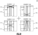
- the first orientation angle ⁇ 1 is equal to approximately 61°
- the second orientation angle ⁇ 2 is equal to approximately -61°
- the third orientation angle ⁇ 3 is equal to approximately 17°
- the fourth orientation angle ⁇ 4 is equal to approximately -17°.
- each of steps 72-78 may be repeated as a subset within the overall steps. For example, in an embodiment, for a cylindrical part, steps 72 and 74 may be repeated three times and then steps 76-78 may be performed so as to define a subset course. Steps 80 and 82 would then be performed as stated thereafter.
- multiple fiber tows 50 are brought together and then laid down as a band 52 on the tool 62 to form the fiber preform 48.
- the same or different fiber types may be used, non-limiting examples of which include carbon (graphite) fibers and glass fibers, as discussed above.
- the thermosetting resin is cured at certain stages in the fiber laying down process. In other embodiments, the thermosetting resin is cured at the end of the laying down process.
- the curing technique may vary depending on the type of resin used, but non-limiting examples of curing techniques include heating the resin, or exposing the resin to ultraviolet (UV) radiation. One common example of heating is accomplished by application of infrared (IR) radiation to the resin or by placement in an enclosed oven or autoclave. The resin chemistry will dictate the type of curing technique that can be used.
- the steps comprise grouping the fiber tows 50 into a number of bands 52 and interweaving in an in-plane and out-of-plane orientation by interleaving each of the plurality of fiber bands 52 with one or more of the plurality of fiber bands 52 previously laid down and not in a common plane to form a winding pattern.
- the gaps 54 in each of the fiber bands 52 as shown in FIGs. 5-9 , generate a secondary, fiber tow 50 based, interleaving within the band 52 as best illustrated in FIGs. 4 and 10 .
- This interleaving may form at least one winding pattern along at least a portion of one or more of the layers 64.
- the fiber tows 50 are grouped to form the fiber bands 52.
- the width of the bands 52 can be adjusted by including more or less tows 50 in each of the fiber bands 52.
- the tightness of the winding pattern may be adjusted to vary the winding pattern.
- a first fiber band is deposited extending at a first orientation angle.
- a second fiber band is deposited, extending at a second orientation angle, different from 180° with respect to the first band, and wherein the second orientation angle is not equal to the first orientation angle.
- a third fiber band is deposited, extending at a third orientation angle, different from 180o with respect to the first fiber band and the second fiber band and wherein the third orientation angle is not equal to the first orientation angle and the second orientation angle.
- At step 78 at least one additional fiber band is deposited, extending at an additional orientation angle, different from 180o with respect to the first fiber band, the second fiber band and the third fiber band and wherein the additional orientation angle is not equal to the first orientation angle, the second orientation angle and the third orientation angle.
- steps 72 - 80 are repeated such that each deposited fiber band has a predetermined spacing from a previously deposited fiber band deposited at an equivalent orientation angle and until a plurality of deposited fiber bands cover an area uniformly and define a course of fiber bands.
- the previous steps are repeated until complete coverage is achieved by depositing an additional plurality of fiber bands such that each band placed during the initial steps is placed immediately adjacent to a respective fiber band with the same orientation angle placed during the subsequent deposition of additional fiber bands.
Landscapes
- Engineering & Computer Science (AREA)
- Mechanical Engineering (AREA)
- Textile Engineering (AREA)
- Chemical & Material Sciences (AREA)
- Composite Materials (AREA)
- Moulding By Coating Moulds (AREA)
- Reinforced Plastic Materials (AREA)
- Woven Fabrics (AREA)
- Nonwoven Fabrics (AREA)
Applications Claiming Priority (2)
| Application Number | Priority Date | Filing Date | Title |
|---|---|---|---|
| US13/906,127 US9249530B2 (en) | 2013-05-30 | 2013-05-30 | Fiber preform architecture for composite articles and method of fabrication |
| PCT/US2014/037854 WO2014193646A1 (en) | 2013-05-30 | 2014-05-13 | Fiber preform architecture for composite articles and method of fabrication |
Publications (2)
| Publication Number | Publication Date |
|---|---|
| EP3003693A1 EP3003693A1 (en) | 2016-04-13 |
| EP3003693B1 true EP3003693B1 (en) | 2021-08-18 |
Family
ID=51033498
Family Applications (1)
| Application Number | Title | Priority Date | Filing Date |
|---|---|---|---|
| EP14734296.8A Active EP3003693B1 (en) | 2013-05-30 | 2014-05-13 | Fiber preform architecture for composite articles and method of fabrication |
Country Status (7)
| Country | Link |
|---|---|
| US (1) | US9249530B2 (https=) |
| EP (1) | EP3003693B1 (https=) |
| JP (1) | JP6521388B2 (https=) |
| CN (1) | CN105492189B (https=) |
| BR (1) | BR112015029493A2 (https=) |
| CA (1) | CA2913537C (https=) |
| WO (1) | WO2014193646A1 (https=) |
Families Citing this family (19)
| Publication number | Priority date | Publication date | Assignee | Title |
|---|---|---|---|---|
| US10519965B2 (en) * | 2016-01-15 | 2019-12-31 | General Electric Company | Method and system for fiber reinforced composite panels |
| US10717512B2 (en) * | 2016-11-03 | 2020-07-21 | Continuous Composites Inc. | Composite vehicle body |
| CN110461918B (zh) * | 2017-03-31 | 2022-06-28 | 三菱化学株式会社 | 预浸料片及其制造方法、带表皮材的单元层、纤维增强复合材料成型品及其制造方法 |
| FR3070402B1 (fr) * | 2017-08-30 | 2020-08-28 | Safran Aircraft Engines | Texture fibreuse tissee pour la formation d'une preforme de carter |
| JP2019114624A (ja) * | 2017-12-22 | 2019-07-11 | スタンレー電気株式会社 | 半導体発光装置及びその製造方法 |
| US10830062B2 (en) | 2018-03-20 | 2020-11-10 | Raytheon Technologies Corporation | Single ply having plurality of fiber angles |
| CN108466437B (zh) * | 2018-03-28 | 2020-04-28 | 中国航发北京航空材料研究院 | 用于带法兰边包容机匣的二维多向预浸布的制备及其应用 |
| US11156126B2 (en) * | 2018-04-13 | 2021-10-26 | Raytheon Technologies Corporation | Fan case with interleaved layers |
| CN111852948B (zh) * | 2019-04-24 | 2022-01-28 | 中国航发商用航空发动机有限责任公司 | 涡扇发动机、风扇机匣及其制造方法 |
| US11149584B2 (en) | 2019-10-07 | 2021-10-19 | General Electric Company | Containment case having ceramic coated fibers |
| CN112709612B (zh) * | 2019-10-24 | 2023-02-28 | 中国航发商用航空发动机有限责任公司 | 一种包容机匣、航空发动机及包容机匣的制造方法 |
| FR3114991B1 (fr) * | 2020-10-12 | 2023-11-03 | Safran Ceram | Texture fibreuse non tissée avec embuvage |
| US20230040244A1 (en) * | 2021-08-06 | 2023-02-09 | Raytheon Technologies Corporation | Composite fan blade airfoil, methods of manufacture thereof and articles comprising the same |
| US12577926B2 (en) | 2022-08-02 | 2026-03-17 | General Electric Company | Gas turbine engine |
| US12012898B2 (en) | 2022-11-03 | 2024-06-18 | General Electric Company | Gas turbine engine with acoustic spacing of the fan blades and outlet guide vanes |
| CN116604840B (zh) * | 2023-04-27 | 2026-01-16 | 中国航发北京航空材料研究院 | 一种双层结构复合材料包容机匣及其制备方法 |
| US12590544B2 (en) | 2023-11-30 | 2026-03-31 | General Electric Company | Composite airfoil |
| US12292017B1 (en) | 2024-06-14 | 2025-05-06 | General Electric Company | Gas turbine engine with acoustic spacing of the fan blades and outlet guide vanes |
| CN119261246B (zh) * | 2024-10-29 | 2025-09-26 | 浙江大学 | 一种碳纤维复合材料平板接头及其制备方法 |
Family Cites Families (20)
| Publication number | Priority date | Publication date | Assignee | Title |
|---|---|---|---|---|
| GB1157526A (en) * | 1965-12-20 | 1969-07-09 | Gen Electric | Improvements in Three Yarn Set Fabrics. |
| JPS5741920A (en) * | 1980-08-27 | 1982-03-09 | Mitsubishi Electric Corp | Manufacture of fiber-reinforced plastic product |
| JPS5855219A (ja) * | 1981-09-29 | 1983-04-01 | Mitsubishi Electric Corp | 繊維強化プラスチツク製品の製造法 |
| US4438173A (en) * | 1983-07-21 | 1984-03-20 | Barber-Colman Company | Triaxial fabric |
| US4671841A (en) * | 1986-01-06 | 1987-06-09 | Rohr Industries, Inc. | Method of making an acoustic panel with a triaxial open-weave face sheet |
| JPH0647022Y2 (ja) * | 1988-08-31 | 1994-11-30 | 東レ株式会社 | 3軸補強織物 |
| BE1007230A3 (nl) * | 1993-06-23 | 1995-04-25 | Dsm Nv | Composietbaan van onderling parallelle vezels in een matrix. |
| US5829979A (en) * | 1996-02-20 | 1998-11-03 | The Kerr Corporation | Reinforcing material for dental appliances and prostheses |
| US6107220A (en) | 1996-10-18 | 2000-08-22 | E. I. Du Pont De Nemours And Company | Rapid fabric forming |
| DE19809264C2 (de) | 1998-03-04 | 2003-06-26 | Eldra Kunststofftechnik Gmbh | Fasergelegeanordnung und Verfahren zur Herstellung eines Vorformlings |
| US7105071B2 (en) | 2001-04-06 | 2006-09-12 | Ebert Composites Corporation | Method of inserting z-axis reinforcing fibers into a composite laminate |
| ITMI20011665A1 (it) * | 2001-07-31 | 2003-01-31 | Mamiliano Dini | Tessuto tetrassiale e macchina per la sua produzione |
| US7018168B2 (en) * | 2004-04-08 | 2006-03-28 | General Electric Company | Method and apparatus for fabricating gas turbine engines |
| US7246990B2 (en) | 2004-12-23 | 2007-07-24 | General Electric Company | Composite fan containment case for turbine engines |
| US7713021B2 (en) | 2006-12-13 | 2010-05-11 | General Electric Company | Fan containment casings and methods of manufacture |
| JP5551411B2 (ja) * | 2009-11-06 | 2014-07-16 | 株式会社Ihi | ケースの製造方法、及びケース |
| EP2353847A1 (en) | 2010-01-28 | 2011-08-10 | Stichting Nationaal Lucht- en Ruimtevaart Laboratorium | Method for making a composite material and structure, composite material and end product |
| US8986797B2 (en) | 2010-08-04 | 2015-03-24 | General Electric Company | Fan case containment system and method of fabrication |
| DE102011080507A1 (de) * | 2011-08-05 | 2013-02-07 | Sgl Carbon Se | Bauteil aus einem Faserverbundwerkstoff |
| ES2427982B1 (es) * | 2012-03-29 | 2014-09-10 | Jordi Galan Llongueras | Tejido plano ultraligero a partir de 2 direcciones de trama |
-
2013
- 2013-05-30 US US13/906,127 patent/US9249530B2/en active Active
-
2014
- 2014-05-13 EP EP14734296.8A patent/EP3003693B1/en active Active
- 2014-05-13 CN CN201480031280.0A patent/CN105492189B/zh active Active
- 2014-05-13 CA CA2913537A patent/CA2913537C/en not_active Expired - Fee Related
- 2014-05-13 WO PCT/US2014/037854 patent/WO2014193646A1/en not_active Ceased
- 2014-05-13 JP JP2016516681A patent/JP6521388B2/ja not_active Expired - Fee Related
- 2014-05-13 BR BR112015029493A patent/BR112015029493A2/pt not_active Application Discontinuation
Non-Patent Citations (1)
| Title |
|---|
| None * |
Also Published As
| Publication number | Publication date |
|---|---|
| CA2913537C (en) | 2018-07-03 |
| JP6521388B2 (ja) | 2019-05-29 |
| US9249530B2 (en) | 2016-02-02 |
| CN105492189B (zh) | 2017-10-13 |
| EP3003693A1 (en) | 2016-04-13 |
| BR112015029493A2 (pt) | 2017-07-25 |
| US20140352838A1 (en) | 2014-12-04 |
| CA2913537A1 (en) | 2014-12-04 |
| CN105492189A (zh) | 2016-04-13 |
| JP2016526116A (ja) | 2016-09-01 |
| WO2014193646A1 (en) | 2014-12-04 |
Similar Documents
| Publication | Publication Date | Title |
|---|---|---|
| EP3003693B1 (en) | Fiber preform architecture for composite articles and method of fabrication | |
| US7713021B2 (en) | Fan containment casings and methods of manufacture | |
| JP2016526116A5 (https=) | ||
| US7246990B2 (en) | Composite fan containment case for turbine engines | |
| US11448090B2 (en) | Fan track liner | |
| US8021102B2 (en) | Composite fan containment case and methods of fabricating the same | |
| US8986797B2 (en) | Fan case containment system and method of fabrication | |
| JP5588103B2 (ja) | ほぼ円筒形の複合材物品及びファンケーシング | |
| EP2913179B1 (en) | Cylindrical case and process for producing cylindrical case | |
| EP2071137B1 (en) | Method for repairing composite containment casings | |
| EP3058199B1 (en) | Compression molded fiber reinforced fan case ice panel | |
| US11149584B2 (en) | Containment case having ceramic coated fibers | |
| US7905972B2 (en) | Methods for making substantially cylindrical articles and fan casings | |
| CN115111184B (zh) | 由混合材料形成的部件 |
Legal Events
| Date | Code | Title | Description |
|---|---|---|---|
| PUAI | Public reference made under article 153(3) epc to a published international application that has entered the european phase |
Free format text: ORIGINAL CODE: 0009012 |
|
| 17P | Request for examination filed |
Effective date: 20160104 |
|
| AK | Designated contracting states |
Kind code of ref document: A1 Designated state(s): AL AT BE BG CH CY CZ DE DK EE ES FI FR GB GR HR HU IE IS IT LI LT LU LV MC MK MT NL NO PL PT RO RS SE SI SK SM TR |
|
| AX | Request for extension of the european patent |
Extension state: BA ME |
|
| DAX | Request for extension of the european patent (deleted) | ||
| STAA | Information on the status of an ep patent application or granted ep patent |
Free format text: STATUS: EXAMINATION IS IN PROGRESS |
|
| 17Q | First examination report despatched |
Effective date: 20190628 |
|
| GRAP | Despatch of communication of intention to grant a patent |
Free format text: ORIGINAL CODE: EPIDOSNIGR1 |
|
| STAA | Information on the status of an ep patent application or granted ep patent |
Free format text: STATUS: GRANT OF PATENT IS INTENDED |
|
| INTG | Intention to grant announced |
Effective date: 20210309 |
|
| GRAS | Grant fee paid |
Free format text: ORIGINAL CODE: EPIDOSNIGR3 |
|
| GRAA | (expected) grant |
Free format text: ORIGINAL CODE: 0009210 |
|
| STAA | Information on the status of an ep patent application or granted ep patent |
Free format text: STATUS: THE PATENT HAS BEEN GRANTED |
|
| AK | Designated contracting states |
Kind code of ref document: B1 Designated state(s): AL AT BE BG CH CY CZ DE DK EE ES FI FR GB GR HR HU IE IS IT LI LT LU LV MC MK MT NL NO PL PT RO RS SE SI SK SM TR |
|
| REG | Reference to a national code |
Ref country code: GB Ref legal event code: FG4D |
|
| REG | Reference to a national code |
Ref country code: CH Ref legal event code: EP |
|
| REG | Reference to a national code |
Ref country code: DE Ref legal event code: R096 Ref document number: 602014079525 Country of ref document: DE |
|
| REG | Reference to a national code |
Ref country code: IE Ref legal event code: FG4D Ref country code: AT Ref legal event code: REF Ref document number: 1421250 Country of ref document: AT Kind code of ref document: T Effective date: 20210915 |
|
| REG | Reference to a national code |
Ref country code: LT Ref legal event code: MG9D |
|
| REG | Reference to a national code |
Ref country code: NL Ref legal event code: MP Effective date: 20210818 |
|
| REG | Reference to a national code |
Ref country code: AT Ref legal event code: MK05 Ref document number: 1421250 Country of ref document: AT Kind code of ref document: T Effective date: 20210818 |
|
| PG25 | Lapsed in a contracting state [announced via postgrant information from national office to epo] |
Ref country code: ES Free format text: LAPSE BECAUSE OF FAILURE TO SUBMIT A TRANSLATION OF THE DESCRIPTION OR TO PAY THE FEE WITHIN THE PRESCRIBED TIME-LIMIT Effective date: 20210818 Ref country code: FI Free format text: LAPSE BECAUSE OF FAILURE TO SUBMIT A TRANSLATION OF THE DESCRIPTION OR TO PAY THE FEE WITHIN THE PRESCRIBED TIME-LIMIT Effective date: 20210818 Ref country code: NO Free format text: LAPSE BECAUSE OF FAILURE TO SUBMIT A TRANSLATION OF THE DESCRIPTION OR TO PAY THE FEE WITHIN THE PRESCRIBED TIME-LIMIT Effective date: 20211118 Ref country code: PT Free format text: LAPSE BECAUSE OF FAILURE TO SUBMIT A TRANSLATION OF THE DESCRIPTION OR TO PAY THE FEE WITHIN THE PRESCRIBED TIME-LIMIT Effective date: 20211220 Ref country code: LT Free format text: LAPSE BECAUSE OF FAILURE TO SUBMIT A TRANSLATION OF THE DESCRIPTION OR TO PAY THE FEE WITHIN THE PRESCRIBED TIME-LIMIT Effective date: 20210818 Ref country code: BG Free format text: LAPSE BECAUSE OF FAILURE TO SUBMIT A TRANSLATION OF THE DESCRIPTION OR TO PAY THE FEE WITHIN THE PRESCRIBED TIME-LIMIT Effective date: 20211118 Ref country code: AT Free format text: LAPSE BECAUSE OF FAILURE TO SUBMIT A TRANSLATION OF THE DESCRIPTION OR TO PAY THE FEE WITHIN THE PRESCRIBED TIME-LIMIT Effective date: 20210818 Ref country code: RS Free format text: LAPSE BECAUSE OF FAILURE TO SUBMIT A TRANSLATION OF THE DESCRIPTION OR TO PAY THE FEE WITHIN THE PRESCRIBED TIME-LIMIT Effective date: 20210818 Ref country code: SE Free format text: LAPSE BECAUSE OF FAILURE TO SUBMIT A TRANSLATION OF THE DESCRIPTION OR TO PAY THE FEE WITHIN THE PRESCRIBED TIME-LIMIT Effective date: 20210818 Ref country code: HR Free format text: LAPSE BECAUSE OF FAILURE TO SUBMIT A TRANSLATION OF THE DESCRIPTION OR TO PAY THE FEE WITHIN THE PRESCRIBED TIME-LIMIT Effective date: 20210818 |
|
| PG25 | Lapsed in a contracting state [announced via postgrant information from national office to epo] |
Ref country code: PL Free format text: LAPSE BECAUSE OF FAILURE TO SUBMIT A TRANSLATION OF THE DESCRIPTION OR TO PAY THE FEE WITHIN THE PRESCRIBED TIME-LIMIT Effective date: 20210818 Ref country code: LV Free format text: LAPSE BECAUSE OF FAILURE TO SUBMIT A TRANSLATION OF THE DESCRIPTION OR TO PAY THE FEE WITHIN THE PRESCRIBED TIME-LIMIT Effective date: 20210818 Ref country code: GR Free format text: LAPSE BECAUSE OF FAILURE TO SUBMIT A TRANSLATION OF THE DESCRIPTION OR TO PAY THE FEE WITHIN THE PRESCRIBED TIME-LIMIT Effective date: 20211119 |
|
| PG25 | Lapsed in a contracting state [announced via postgrant information from national office to epo] |
Ref country code: NL Free format text: LAPSE BECAUSE OF FAILURE TO SUBMIT A TRANSLATION OF THE DESCRIPTION OR TO PAY THE FEE WITHIN THE PRESCRIBED TIME-LIMIT Effective date: 20210818 |
|
| PG25 | Lapsed in a contracting state [announced via postgrant information from national office to epo] |
Ref country code: DK Free format text: LAPSE BECAUSE OF FAILURE TO SUBMIT A TRANSLATION OF THE DESCRIPTION OR TO PAY THE FEE WITHIN THE PRESCRIBED TIME-LIMIT Effective date: 20210818 |
|
| REG | Reference to a national code |
Ref country code: DE Ref legal event code: R097 Ref document number: 602014079525 Country of ref document: DE |
|
| PG25 | Lapsed in a contracting state [announced via postgrant information from national office to epo] |
Ref country code: SM Free format text: LAPSE BECAUSE OF FAILURE TO SUBMIT A TRANSLATION OF THE DESCRIPTION OR TO PAY THE FEE WITHIN THE PRESCRIBED TIME-LIMIT Effective date: 20210818 Ref country code: SK Free format text: LAPSE BECAUSE OF FAILURE TO SUBMIT A TRANSLATION OF THE DESCRIPTION OR TO PAY THE FEE WITHIN THE PRESCRIBED TIME-LIMIT Effective date: 20210818 Ref country code: RO Free format text: LAPSE BECAUSE OF FAILURE TO SUBMIT A TRANSLATION OF THE DESCRIPTION OR TO PAY THE FEE WITHIN THE PRESCRIBED TIME-LIMIT Effective date: 20210818 Ref country code: EE Free format text: LAPSE BECAUSE OF FAILURE TO SUBMIT A TRANSLATION OF THE DESCRIPTION OR TO PAY THE FEE WITHIN THE PRESCRIBED TIME-LIMIT Effective date: 20210818 Ref country code: CZ Free format text: LAPSE BECAUSE OF FAILURE TO SUBMIT A TRANSLATION OF THE DESCRIPTION OR TO PAY THE FEE WITHIN THE PRESCRIBED TIME-LIMIT Effective date: 20210818 Ref country code: AL Free format text: LAPSE BECAUSE OF FAILURE TO SUBMIT A TRANSLATION OF THE DESCRIPTION OR TO PAY THE FEE WITHIN THE PRESCRIBED TIME-LIMIT Effective date: 20210818 |
|
| PLBE | No opposition filed within time limit |
Free format text: ORIGINAL CODE: 0009261 |
|
| STAA | Information on the status of an ep patent application or granted ep patent |
Free format text: STATUS: NO OPPOSITION FILED WITHIN TIME LIMIT |
|
| 26N | No opposition filed |
Effective date: 20220519 |
|
| PG25 | Lapsed in a contracting state [announced via postgrant information from national office to epo] |
Ref country code: IT Free format text: LAPSE BECAUSE OF FAILURE TO SUBMIT A TRANSLATION OF THE DESCRIPTION OR TO PAY THE FEE WITHIN THE PRESCRIBED TIME-LIMIT Effective date: 20210818 |
|
| PG25 | Lapsed in a contracting state [announced via postgrant information from national office to epo] |
Ref country code: SI Free format text: LAPSE BECAUSE OF FAILURE TO SUBMIT A TRANSLATION OF THE DESCRIPTION OR TO PAY THE FEE WITHIN THE PRESCRIBED TIME-LIMIT Effective date: 20210818 |
|
| REG | Reference to a national code |
Ref country code: CH Ref legal event code: PL |
|
| REG | Reference to a national code |
Ref country code: BE Ref legal event code: MM Effective date: 20220531 |
|
| PG25 | Lapsed in a contracting state [announced via postgrant information from national office to epo] |
Ref country code: MC Free format text: LAPSE BECAUSE OF FAILURE TO SUBMIT A TRANSLATION OF THE DESCRIPTION OR TO PAY THE FEE WITHIN THE PRESCRIBED TIME-LIMIT Effective date: 20210818 Ref country code: LU Free format text: LAPSE BECAUSE OF NON-PAYMENT OF DUE FEES Effective date: 20220513 Ref country code: LI Free format text: LAPSE BECAUSE OF NON-PAYMENT OF DUE FEES Effective date: 20220531 Ref country code: CH Free format text: LAPSE BECAUSE OF NON-PAYMENT OF DUE FEES Effective date: 20220531 |
|
| PG25 | Lapsed in a contracting state [announced via postgrant information from national office to epo] |
Ref country code: IE Free format text: LAPSE BECAUSE OF NON-PAYMENT OF DUE FEES Effective date: 20220513 |
|
| PG25 | Lapsed in a contracting state [announced via postgrant information from national office to epo] |
Ref country code: BE Free format text: LAPSE BECAUSE OF NON-PAYMENT OF DUE FEES Effective date: 20220531 |
|
| P01 | Opt-out of the competence of the unified patent court (upc) registered |
Effective date: 20230414 |
|
| PG25 | Lapsed in a contracting state [announced via postgrant information from national office to epo] |
Ref country code: HU Free format text: LAPSE BECAUSE OF FAILURE TO SUBMIT A TRANSLATION OF THE DESCRIPTION OR TO PAY THE FEE WITHIN THE PRESCRIBED TIME-LIMIT; INVALID AB INITIO Effective date: 20140513 |
|
| PG25 | Lapsed in a contracting state [announced via postgrant information from national office to epo] |
Ref country code: MK Free format text: LAPSE BECAUSE OF FAILURE TO SUBMIT A TRANSLATION OF THE DESCRIPTION OR TO PAY THE FEE WITHIN THE PRESCRIBED TIME-LIMIT Effective date: 20210818 Ref country code: CY Free format text: LAPSE BECAUSE OF FAILURE TO SUBMIT A TRANSLATION OF THE DESCRIPTION OR TO PAY THE FEE WITHIN THE PRESCRIBED TIME-LIMIT Effective date: 20210818 |
|
| PG25 | Lapsed in a contracting state [announced via postgrant information from national office to epo] |
Ref country code: MT Free format text: LAPSE BECAUSE OF FAILURE TO SUBMIT A TRANSLATION OF THE DESCRIPTION OR TO PAY THE FEE WITHIN THE PRESCRIBED TIME-LIMIT Effective date: 20210818 |
|
| PGFP | Annual fee paid to national office [announced via postgrant information from national office to epo] |
Ref country code: DE Payment date: 20250423 Year of fee payment: 12 |
|
| PGFP | Annual fee paid to national office [announced via postgrant information from national office to epo] |
Ref country code: GB Payment date: 20250423 Year of fee payment: 12 |
|
| PGFP | Annual fee paid to national office [announced via postgrant information from national office to epo] |
Ref country code: FR Payment date: 20250423 Year of fee payment: 12 |
|
| PG25 | Lapsed in a contracting state [announced via postgrant information from national office to epo] |
Ref country code: TR Free format text: LAPSE BECAUSE OF FAILURE TO SUBMIT A TRANSLATION OF THE DESCRIPTION OR TO PAY THE FEE WITHIN THE PRESCRIBED TIME-LIMIT Effective date: 20210818 |