EP3003634B1 - Crossjet-anordnung sowie verfahren zum wegführen von kontaminationen - Google Patents
Crossjet-anordnung sowie verfahren zum wegführen von kontaminationen Download PDFInfo
- Publication number
- EP3003634B1 EP3003634B1 EP14728887.2A EP14728887A EP3003634B1 EP 3003634 B1 EP3003634 B1 EP 3003634B1 EP 14728887 A EP14728887 A EP 14728887A EP 3003634 B1 EP3003634 B1 EP 3003634B1
- Authority
- EP
- European Patent Office
- Prior art keywords
- crossjet
- gas flow
- working
- area
- arrangement according
- Prior art date
- Legal status (The legal status is an assumption and is not a legal conclusion. Google has not performed a legal analysis and makes no representation as to the accuracy of the status listed.)
- Not-in-force
Links
- 239000000356 contaminant Substances 0.000 title claims description 17
- 238000000034 method Methods 0.000 title claims description 8
- 239000002245 particle Substances 0.000 claims description 18
- 238000003466 welding Methods 0.000 claims description 10
- 238000004804 winding Methods 0.000 claims description 9
- 238000011109 contamination Methods 0.000 claims description 8
- 239000007789 gas Substances 0.000 description 30
- 230000005855 radiation Effects 0.000 description 8
- 239000012535 impurity Substances 0.000 description 4
- 230000008901 benefit Effects 0.000 description 3
- 238000003754 machining Methods 0.000 description 3
- 238000002679 ablation Methods 0.000 description 2
- 239000011324 bead Substances 0.000 description 2
- 239000002184 metal Substances 0.000 description 2
- 230000008569 process Effects 0.000 description 2
- 230000001681 protective effect Effects 0.000 description 2
- 238000005520 cutting process Methods 0.000 description 1
- 238000005553 drilling Methods 0.000 description 1
- 238000000227 grinding Methods 0.000 description 1
- 239000001307 helium Substances 0.000 description 1
- 229910052734 helium Inorganic materials 0.000 description 1
- SWQJXJOGLNCZEY-UHFFFAOYSA-N helium atom Chemical compound [He] SWQJXJOGLNCZEY-UHFFFAOYSA-N 0.000 description 1
- 230000006872 improvement Effects 0.000 description 1
- 230000003993 interaction Effects 0.000 description 1
- 238000003698 laser cutting Methods 0.000 description 1
- 229910001338 liquidmetal Inorganic materials 0.000 description 1
- 238000004519 manufacturing process Methods 0.000 description 1
- 239000000463 material Substances 0.000 description 1
- 230000007246 mechanism Effects 0.000 description 1
- 238000003801 milling Methods 0.000 description 1
- 230000009467 reduction Effects 0.000 description 1
- 239000000779 smoke Substances 0.000 description 1
- 238000007514 turning Methods 0.000 description 1
Images


Classifications
-
- B—PERFORMING OPERATIONS; TRANSPORTING
- B23—MACHINE TOOLS; METAL-WORKING NOT OTHERWISE PROVIDED FOR
- B23K—SOLDERING OR UNSOLDERING; WELDING; CLADDING OR PLATING BY SOLDERING OR WELDING; CUTTING BY APPLYING HEAT LOCALLY, e.g. FLAME CUTTING; WORKING BY LASER BEAM
- B23K26/00—Working by laser beam, e.g. welding, cutting or boring
- B23K26/14—Working by laser beam, e.g. welding, cutting or boring using a fluid stream, e.g. a jet of gas, in conjunction with the laser beam; Nozzles therefor
- B23K26/142—Working by laser beam, e.g. welding, cutting or boring using a fluid stream, e.g. a jet of gas, in conjunction with the laser beam; Nozzles therefor for the removal of by-products
-
- B—PERFORMING OPERATIONS; TRANSPORTING
- B08—CLEANING
- B08B—CLEANING IN GENERAL; PREVENTION OF FOULING IN GENERAL
- B08B15/00—Preventing escape of dirt or fumes from the area where they are produced; Collecting or removing dirt or fumes from that area
- B08B15/007—Fume suction nozzles arranged on a closed or semi-closed surface, e.g. on a circular, ring-shaped or rectangular surface adjacent the area where fumes are produced
-
- B—PERFORMING OPERATIONS; TRANSPORTING
- B23—MACHINE TOOLS; METAL-WORKING NOT OTHERWISE PROVIDED FOR
- B23K—SOLDERING OR UNSOLDERING; WELDING; CLADDING OR PLATING BY SOLDERING OR WELDING; CUTTING BY APPLYING HEAT LOCALLY, e.g. FLAME CUTTING; WORKING BY LASER BEAM
- B23K26/00—Working by laser beam, e.g. welding, cutting or boring
- B23K26/14—Working by laser beam, e.g. welding, cutting or boring using a fluid stream, e.g. a jet of gas, in conjunction with the laser beam; Nozzles therefor
-
- B—PERFORMING OPERATIONS; TRANSPORTING
- B23—MACHINE TOOLS; METAL-WORKING NOT OTHERWISE PROVIDED FOR
- B23K—SOLDERING OR UNSOLDERING; WELDING; CLADDING OR PLATING BY SOLDERING OR WELDING; CUTTING BY APPLYING HEAT LOCALLY, e.g. FLAME CUTTING; WORKING BY LASER BEAM
- B23K26/00—Working by laser beam, e.g. welding, cutting or boring
- B23K26/14—Working by laser beam, e.g. welding, cutting or boring using a fluid stream, e.g. a jet of gas, in conjunction with the laser beam; Nozzles therefor
- B23K26/1462—Nozzles; Features related to nozzles
- B23K26/1464—Supply to, or discharge from, nozzles of media, e.g. gas, powder, wire
- B23K26/1476—Features inside the nozzle for feeding the fluid stream through the nozzle
-
- B—PERFORMING OPERATIONS; TRANSPORTING
- B23—MACHINE TOOLS; METAL-WORKING NOT OTHERWISE PROVIDED FOR
- B23K—SOLDERING OR UNSOLDERING; WELDING; CLADDING OR PLATING BY SOLDERING OR WELDING; CUTTING BY APPLYING HEAT LOCALLY, e.g. FLAME CUTTING; WORKING BY LASER BEAM
- B23K26/00—Working by laser beam, e.g. welding, cutting or boring
- B23K26/20—Bonding
- B23K26/21—Bonding by welding
-
- B—PERFORMING OPERATIONS; TRANSPORTING
- B23—MACHINE TOOLS; METAL-WORKING NOT OTHERWISE PROVIDED FOR
- B23K—SOLDERING OR UNSOLDERING; WELDING; CLADDING OR PLATING BY SOLDERING OR WELDING; CUTTING BY APPLYING HEAT LOCALLY, e.g. FLAME CUTTING; WORKING BY LASER BEAM
- B23K26/00—Working by laser beam, e.g. welding, cutting or boring
- B23K26/70—Auxiliary operations or equipment
- B23K26/702—Auxiliary equipment
Definitions
- the invention relates to a crossjet arrangement for producing a gas stream guided between a processing device, such as a laser, and a processing region, such as welding region, through a removal region for carrying away contaminants, such as particles or vapors, which are produced in the processing region and move in the direction of the processing device ,
- the invention also relates to a method for removing contaminants moving from a processing location in the direction of a processing device by means of a gas flow.
- gases or plasma emissions are generated, which can lead to contamination of the processing device and thus influence its function.
- a gas flow is generated transversely to the main direction of flight of the contaminants in a so-called crossjet arrangement targeted to entrain the contaminants and thus at least largely prevent contamination of the processing device.
- the pollution mechanism consists in a mass transfer from the machining process to the machining facility.
- the gas stream or Crossjet is intended to detect and deflect the impurities on their way to the processing device so that they can no longer reach the processing device, or at least the areas which are to be protected, in particular.
- a housing has an opening, which is penetrated by the laser radiation. Transverse to this cross-beam radiation is generated, wherein the outlet opening of the radiation has a smaller diameter than the inlet opening.
- a Laval nozzle for a Crossjet device is from the DE 203 18 461 U1 known.
- a crossjet arrangement as in the preamble of claim 1 is the US 2004/0026388 A1 can be seen in which a gas flow is guided transversely to a laser beam of a laser welding device.
- a helium stream is guided parallel to the ablation radiation.
- a Koaxialjet arrangement is the EP 1 016 494 A2 refer to.
- a gas stream is repeatedly coaxially guided to a laser beam. Centrifugal forces act on the gas flow by means of an impeller.
- the present invention is based on the object, a Crossjet arrangement and a method of the type mentioned in such a way that with simple design measures, a gas stream is generated with the extent sufficient contaminants are detected or deflected such that a processing facility before Pollution is protected.
- the invention essentially provides that the gas stream is repeatedly guided over at least one deflection by the Weglim Kunststoff Scheme such that the gas flow repeatedly crosses the running between the processing device and the processing area way, wherein the deflection means a gas flow leading spirally Has multi-turn lane and windings are interrupted in the Weglim Society
- the deflection meanderformig extending deflections or channels which are interrupted in the Weglim Society.
- the gas stream used to deflect the contamination is routed multiple times through the removal area so that the gas pressure and amount of gas used to carry away or deflect the contaminants may correspond to those used in known arrangements, but at the same time Higher degree of deflection and thus protection for the processing device takes place.
- the gas and air flow is deflected so that the impurities are detected or influenced on their way to the processing device from the gas flow multiple times or over a longer path, whereby a significant improvement in the protective effect is achieved or used in comparison to the prior art Arrangement a lower gas consumption is required to achieve the same protective effect.
- the turns can span a plane that runs in particular inclined to the direction of movement of the contamination.
- outlet openings or inlet openings are arranged one above the other in the direction of movement of the contaminations.
- the deflection device is formed in a preferably cuboidal housing which has a cutout delimiting the removal area.
- the cutout has two mutually parallel boundaries which are penetrated by the inlet and outlet openings of the turns of the spiral path or the meandering channels or in which circular section-shaped recesses are formed as the meander-shaped deflections ,
- a method for carrying away contaminants moving from a processing location in the direction of a processing device by means of a gas stream is characterized in that the gas stream is deflected for multiple passage through the direction such that the gas stream repeatedly crosses the path extending between the processing device and the processing area.
- the gas flow is deflected through sections of a spirally running path or by means of meander-shaped guides.
- a corresponding gas flow - referred to below as air flow - is deflected several times in the region of the dirt particles moving in the direction of the processing device, so that the dirt particles are repeatedly exposed to the air flow with the result that a deflection of the dirt particles and thus shooters of the Machining device is largely ensured.
- the invention provides by way of example several possibilities.
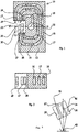
- a spiral-shaped channel 14 having a plurality of turns 16, 17, 18 which are interrupted in a designated as Weg réelle Society area 20, which is penetrated in the embodiment of the laser radiation. It runs in Fig. 1 the laser radiation into the plane of the drawing.
- impurities thrown away from the processing area have a direction of flight which emerges from the plane of the drawing.
- the corresponding dirt particles are exemplified as open circles and designated by the reference numeral 22.
- the windings 16, 17, 18 are interrupted in the Weglim Colour Republic 20, wherein the outlet openings 26, 27 of the windings 16, 17 are aligned with inlet openings 36, 37 which extend opposite to the inlet openings 26, 27, as well as the sectional view of Fig. 1 shows.
- the air flow leaving the outlet opening 28 of the winding 18 is then guided laterally past the housing 12, as the arrow 30 illustrates.
- an air pressure source is connected to the beginning of the winding 16.
- the area forms the air supply 32.
- the turns 16, 17, 18 running in a plane can run obliquely to the main flight direction 34 of the dirt particles ( Fig. 3 ).
- the air emerging from the outlet openings 26, 27, 28 thus detects the dirt particles independently of the trajectory, since a complete covering of the directions of flight of the dirt particles takes place by the inclination of the rectangular outlet openings 26, 27, 28 in the exemplary embodiment.
- the crossjet arrangement 10 with the air emerging via the outlet openings 26, 27, 28 runs between a processing device such as a laser source 40 and a processing station 42 (processing region).
- Fig. 4 to 7 it is a crossjet arrangement 44, in which also a spiral-shaped channel 46 is formed.
- the spiral channel 46 is three-dimensional, so that the outlet openings 48, 50, 52 are arranged one above the other in relation to the main direction of flight of the contaminants.
- the crossjet assembly 44 has a housing 54 with a cutout 56 which forms the Weglim Society.
- the outlet openings 48, 50, 52 of the spiral channel 46 extend in a boundary wall 58 of the cutout 56.
- corresponding inlet openings are provided, according to the embodiment of Fig. 1 to 3 , according to the embodiment of Fig. 1 to 3 the outlet opening 48 and 50 is assigned in each case one in the wall 60 existing in the spiral-shaped channel 46 merging inlet opening.
- the emerging from the outlet opening 52 air air then flows into the open air.
- an air connection 62 is shown, is supplied via the air to the spiral channel 46.
- a meandering deflection of an air stream is performed to keep particles being ejected from a processing location, such as welding location 68, from a processing device, such as laser source 76.
- a processing location such as welding location 68
- a processing device such as laser source 76.
- a third embodiment forming Crossjet arrangement 70 is arranged with a housing 72 having a rectangular cross-section through opening 78, which is penetrated by the laser radiation and thus also by the dirt particles.
- Opposite walls 80, 82 of the opening 78 have recesses or recesses 84, 86, 88 in the form of a circular segment, so that an air supplied via an air connection 86 to a channel and exiting therefrom is deflected via the recesses 84, 86, 88 with the result that the between the walls 80, 82, which limit a Weg réelle Scheme 90, flowing air can deflect the entering in the Weglim Society 90 dirt particles and thus can lead away.
- the contaminants are repeatedly exposed to the air flow on their way to a processing device such as laser or by tilting the cross-jet assembly 10 according to the Fig. 1 to 3 takes place on a relatively long way an interaction between air flow and the pollution.
Landscapes
- Engineering & Computer Science (AREA)
- Physics & Mathematics (AREA)
- Optics & Photonics (AREA)
- Plasma & Fusion (AREA)
- Mechanical Engineering (AREA)
- Laser Beam Processing (AREA)
Description
- Die Erfindung bezieht sich auf eine Crossjet-Anordnung zum Erzeugen eines zwischen einer Bearbeitungseinrichtung, wie Laser, und einem Bearbeitungsbereich, wie Schweißbereich, durch einen Wegführbereich geführten Gasstrom zum Wegführen von im Bearbeitungsbereich entstehenden und sich in Richtung der Bearbeitungseinrichtung bewegenden Kontaminationen, wie Partikel oder Dämpfe. Auch nimmt die Erfindung Bezug auf ein Verfahren zum Wegführen von sich von einem Bearbeitungsort in Richtung einer Bearbeitungseinrichtung bewegenden Kontaminationen mittels eines Gasstroms.
- Bei verschiedenen Fertigungsprozessen wie Bohren, Schleifen, Drehen, Fräsen, Schweißen oder Schneiden verschiedener Werkstoffe fallen Späne, Spritzer oder Rauch, Gase oder Plasmaemissionen an, die zu Verunreinigungen der Bearbeitungseinrichtung führen und damit ihre Funktion beeinflussen können. Um Verunreinigungen von Bearbeitungseinrichtungen wie Laser zu verhindern oder zumindest abzuschwächen, ist es bekannt, zwischen dem Bearbeitungsbereich und der Bearbeitungseinrichtung, d. h., deren besonders empfindlichen Bereichen, wie Austrittsfenster für Laserstrahlung beim Laserschneiden oder -schweißen, einen Gasstrom einzusetzen. Dabei wird gezielt ein Gasstrom quer zur Hauptflugrichtung der Kontaminationen in einer sogenannten Crossjet-Anordnung erzeugt, um die Kontaminationen mitzureißen und somit eine Verschmutzung der Bearbeitungseinrichtung zumindest weitgehend zu verhindern.
- Der Verschmutzungsmechanismus besteht in einem Stofftransport vom Bearbeitungsprozess zur Bearbeitungseinrichtung. Der Gasstrom bzw. Crossjet soll die Verunreinigungen auf ihrem Weg zu der Bearbeitungseinrichtung hin erfassen und ablenken, so dass diese die Bearbeitungseinrichtung nicht mehr oder zumindest die besonders zu schützenden Bereiche nicht mehr erreichen können.
- Insbesondere beim Lasertiefschweißen können sich Metallkügelchen oder flüssige Metalltropfen mit hoher Geschwindigkeit vom Prozess in Richtung des Laseraustrittsfensters bewegen.
Der Gasstrom muss in diesem Fall soweit ausgedehnt sein, dass der gesamte besonders empfindliche Bereich der Bearbeitungseinrichtung geschützt ist. Ferner muss die Geschwindigkeit des Gasstroms so groß sein, dass eine hinreichende Ablenkung der Metallkügelchen bzw. -tropfen erreicht wird. Die maximal zur Verfügung stehende Gasmenge ist in der Anwendung durch die vorhandenen Leitungsquerschnitte und den anstehenden Luftdruck begrenzt. Gleiches gilt für die Strömungsgeschwindigkeit. Daher lässt sich in der Praxis häufig kein vollständiger Schutz der Bearbeitungseinrichtung erzielen, so dass die Bearbeitungseinrichtung kontaminiert wird. Somit ist es erforderlich, dass die entsprechenden Bauteile nach einer vorgegebenen Anzahl von Anwendungen gereinigt oder ausgetauscht werden.
DerEP-1 607 167 A1 ist eine Crossjet-Vorrichtung für einen Laserhybrid-Schweißprozess zu entnehmen. Ein Gehäuse weist eine Öffnung auf, die von der Laserstrahlung durchsetzt wird. Quer zu dieser wird eine Crossjet-Strahlung erzeugt, wobei die Austrittsöffnung der Strahlung einen kleineren Durchmesser als die Eintrittsöffnung aufweist.
Eine Laval-Düse für eine Crossjet-Vorrichtung ist aus derDE 203 18 461 U1 bekannt. - Eine Crossjet-Anordnung wie im Oberbegriff des Anspruchs 1 ist der
US 2004/0026388 A1 zu entnehmen, bei der ein Gasstrom quer zu einem Laserstrahl einer Laserschweißvorrichtung geführt wird. Um bei der Foto-Ablation entstehende Partikel wegzuführen, wird nach derUS 2009/0107966 A1 ein Heliumstrom parallel zur Ablationsstrahlung geführt. - Eine Koaxialjet-Anordnung ist der
EP 1 016 494 A2 zu entnehmen. Dabei wird ein Gasstrom mehrfach koaxial zu einem Laserstrahl geführt. Auf den Gasstrom wirken mittels eines Flügelrads Zentrifugalkräfte ein. - Der vorliegenden Erfindung liegt die Aufgabe zu Grunde, eine Crossjet-Anordnung sowie ein Verfahren der eingangs genannten Art so weiterzubilden, dass mit konstruktiv einfachen Maßnahmen ein Gasstrom erzeugt wird, mit dem im hinreichenden Umfang Kontaminationen derart erfasst bzw. abgelenkt werden, dass eine Bearbeitungseinrichtung vor Verschmutzungen geschützt ist.
- Zur Lösung der Aufgabe sieht die Erfindung im Wesentlichen vor, dass der Gasstrom über zumindest eine Umlenkeinrichtung mehrfach durch den Wegführbereich derart geführt ist, dass der Gasstrom mehrfach den zwischen der Bearbeitungseinrichtung und dem Bearbeitungsbereich verlaufenden Weg kreuzt, wobei die Umlenkeinrichtung eine den Gasstrom führende spiralartig verlaufende Bahn mit mehreren Windungen aufweist und Windungen in dem Wegführbereich unterbrochen sind, oder die Umlenkeinrichtung mäanderformig verlaufende Umlenkungen oder Kanäle aufweist, die im Wegführbereich unterbrochen sind.
- Aufgrund der erfindungsgemäßen Lehre wird der zum Ablenken der Kontamination benutzte Gasstrom mehrfach durch den Wegführbereich geführt, so dass Gasdruck und Gasmenge, die zum Wegführen bzw. Ablenken der Kontaminationen benutzt werden, solchen entsprechen können, die bei bekannten Anordnungen zum Einsatz gelangen, gleichzeitig jedoch ein höherer Grad der Ablenkung und damit ein Schutz für die Bearbeitungseinrichtung erfolgt. Erfindungsgemäß wird der Gas- wie Luftstrom so umgelenkt, dass die Verunreinigungen auf ihrem Weg zur Bearbeitungseinrichtung vom Gasstrom mehrfach oder auf einer größeren Weglänge erfasst bzw. beeinflusst werden, wodurch eine deutliche Verbesserung der Schutzwirkung erzielt wird oder bei einer im Vergleich zum Stand der Technik benutzten Anordnung ein geringerer Gasverbrauch erforderlich ist, um die gleiche Schutzwirkung zu erzielen.
- Dabei können die Windungen eine Ebene aufspannen, die insbesondere geneigt zur Bewegungsrichtung der Kontamination verläuft.
- Es besteht jedoch auch die Möglichkeit, die spiralartig verlaufende Bahn dreidimensional auszubilden.
- Bei einer dreidimensional verlaufenden spiralartig verlaufenden Bahn sind die Austritts- bzw. Eintrittsöffnungen in Bewegungsrichtung der Kontaminationen übereinander angeordnet.
- Um den Gasstrom umzulenken, damit dieser mehrfach den Wegführbereich durchsetzt, sieht ein weiterer erfindungsgemäßer Vorschlag vor, dass die Umlenkeinrichtung mäanderförmig wirkende Umlenkungen oder mäanderförmig verlaufende Kanäle aufweist, die im Wegführbereich unterbrochen sind.
- Insbesondere ist vorgesehen, dass die Umlenkeinrichtung in einem vorzugsweise quaderförmigen Gehäuse ausgebildet ist, das einen den Wegführbereich begrenzenden Ausschnitt aufweist.
- Bevorzugterweise ist vorgesehen, dass der Ausschnitt zwei parallel zueinander verlaufende Begrenzungen aufweist, die von den Ein- bzw. Austrittsöffnungen der Windungen der spiralartig verlaufenden Bahn bzw. der mäanderförmigen Kanäle durchsetzt sind bzw. in denen im Schnitt kreisabschnittförmige Aussparungen als die mäanderförmig wirkenden Umlenkungen ausgebildet sind.
- Ein Verfahren zum Wegführen von sich von einem Bearbeitungsort in Richtung einer Bearbeitungseinrichtung bewegenden Kontaminationen mittels eines Gasstroms zeichnet sich dadurch aus, dass der Gasstrom zum mehrfachen Durchsetzen der Richtung derart umgelenkt wird, dass der Gasstrom mehrfach den zwischen der Bearbeitungseinrichtung und dem Bearbeitungsbereich verlaufenden Weg kreuzt.
- Insbesondere ist vorgesehen, dass der Gasstrom durch Abschnitte einer spiralförmig verlaufenden Bahn oder mittels mäanderförmig ausgebildeter Führungen umgelenkt wird.
- Weitere Einzelheiten, Vorteile und Merkmale der Erfindung ergeben sich nicht nur aus den Ansprüchen, den diesen zu entnehmenden Merkmalen - für sich und/oder in Kombination -, sondern auch aus der nachfolgenden Beschreibung von der Zeichnung zu entnehmenden bevorzugten Ausführungsbeispielen.
- Es zeigen:
- Fig. 1
- eine erste Ausführungsform einer Crossjet-Anordnung,
- Fig. 2
- einen Schnitt entlang der Linie II-II in
Fig. 1 , - Fig. 3
- einen Ausschnitt der Anordnung gemäß
Fig. 1 , - Fig. 4
- eine zweite Ausführungsform einer Crossjet-Anordnung,
- Fig. 5
- einen Schnitt entlang der Linie V-V in
Fig. 4 , - Fig. 6
- Ansicht der Anordnung gemäß
Fig. 4 in Richtung Pfeil 6, - Fig. 7
- eine Draufsicht auf die Anordnung gemäß
Fig. 4 , - Fig. 8
- eine dritte Ausführungsform einer Crossjet-Anordnung,
- Fig. 9
- einen Schnitt entlang der Linie IX-IX in
Fig. 8 und - Fig. 10
- eine Variante der Anordnung gemäß
Fig. 8 . - In den Figuren sind rein schematisch verschiedene Ausführungsformen von Crossjet-Anordnungen dargestellt, mit denen ein Gas- wie Luftstrom derart geführt wird, dass die von einem Bearbeitungsbereich in Richtung einer Bearbeitungseinrichtung sich bewegenden Kontaminationen, wie Schmutzpartikel, gezielt weggeführt werden, um die Bearbeitungseinrichtung zu schützen. Bei dieser kann es sich um eine Lasereinrichtung wie Laserschweißeinrichtung handeln, mit der im Bearbeitungsbereich, also Schweißbereich Werkstücke geschweißt werden sollen, ohne dass hierdurch die erfindungsgemäße Lehre eingeschränkt wird.
- Um Kontaminationen - nachstehend vereinfacht Schmutzpartikel genannt - von der Bearbeitungseinrichtung, wie Austrittsfenster eines Lasers, zu schützen, ist es bekannt, Crossjet-Anordnungen zu verwenden, wobei ein Luftstrom quer zur Flug- bzw. Hauptflugrichtung der Schmutzpartikel zwischen dem Bearbeitungsort und der Bearbeitungseinrichtung strömt, um die Schmutzpartikel abzulenken und somit diese zu hindern, auf die Bearbeitungseinrichtung zu treffen bzw. deren zu schützende Bereiche.
- Erfindungsgemäß ist vorgesehen, dass ein entsprechender Gasstrom - nachstehend Luftstrom genannt - mehrfach im Bereich der sich in Richtung der Bearbeitungseinrichtung bewegenden Schmutzpartikel umgelenkt wird, so dass infolgedessen die Schmutzpartikel mehrfach dem Luftstrom ausgesetzt sind mit der Folge, dass ein Ablenken der Schmutzpartikel und damit Schützen der Bearbeitungseinrichtung weitgehend sichergestellt ist.
- Um eine diesbezügliche mehrfache Umlenkung des Luftstroms zu erreichen, sieht die Erfindung beispielhaft mehrere Möglichkeiten vor. So ist bei der Crossjet-Anordnung 10 gemäß der
Fig. 1 bis 3 in einem Gehäuse 12 ein spiralförmig verlaufender Kanal 14 ausgebildet, der mehrere Windungen 16, 17, 18 aufweist, die in einem als Wegführbereich bezeichneten Bereich 20 unterbrochen sind, der im Ausführungsbeispiel von der Laserstrahlung durchsetzt wird. Dabei verläuft inFig. 1 die Laserstrahlung in die Zeichenebene hinein. Von dem Bearbeitungsbereich wegeschleuderte Verschmutzungen weisen demzufolge eine Flugrichtung auf, die aus der Zeichenebene heraustritt. Die entsprechenden Schmutzpartikel sind beispielhaft als offene Kreise und mit dem Bezugszeichen 22 gekennzeichnet. - Die Windungen 16, 17, 18 sind im Wegführbereich 20 unterbrochen, wobei die Austrittsöffnungen 26, 27 der Windungen 16, 17 auf Eintrittsöffnungen 36, 37 ausgerichtet sind, die gegenüberliegend zu den Eintrittsöffnungen 26, 27 verlaufen, wie auch die Schnittdarstellung der
Fig. 1 zeigt. Der die Austrittsöffnung 28 der Windung 18 verlassende Luftstrom wird sodann seitlich an dem Gehäuse 12 vorbeigeführt, wie der Pfeil 30 verdeutlicht. Ferner ist erkennbar, dass eine Luftdruckquelle mit dem Anfang der Windung 16 verbunden ist. Der Bereich bildet die Luftzuführung 32. - Damit die Schmutzpartikel 22 stets von einem aus den Austrittsöffnungen 26, 27, 28 austretenden Luftstrom erfasst werden, können die in einer Ebene verlaufenden Windungen 16, 17, 18 geneigt zur Hauptflugrichtung 34 der Schmutzpartikel verlaufen (
Fig. 3 ). Die aus den Austrittsöffnungen 26, 27, 28 austretende Luft erfasst somit unabhängig von der Flugbahn die Schmutzpartikel, da durch die Neigung der im Ausführungsbeispiel rechteckförmigen Austrittsöffnungen 26, 27, 28 eine vollständige Abdeckung der Flugrichtungen der Schmutzpartikel erfolgt. - Aus der
Fig. 3 ergibt sich des Weiteren, dass die Crossjet-Anordnung 10 mit der über die Austrittsöffnungen 26, 27, 28 austretenden Luft zwischen einer Bearbeitungseinrichtung wie Laserquelle 40 und einem Prozessort 42 (Bearbeitungsbereich) verläuft. - Bei dem Ausführungsbeispiel der
Fig. 4 bis 7 handelt es sich um eine Crossjet-Anordnung 44, in der ebenfalls ein spiralförmig verlaufender Kanal 46 ausgebildet ist. Der spiralförmige Kanal 46 verläuft dreidimensional, so dass die Austrittsöffnungen 48, 50, 52 in Bezug auf die Hauptflugrichtung der Verschmutzungen übereinander angeordnet sind. - Aus den Darstellungen der
Fig. 4, 6 und 7 ist erkennbar, dass die Crossjet-Anordnung 44 ein Gehäuse 54 mit einem Ausschnitt 56 aufweist, der den Wegführbereich bildet. Die Austrittsöffnungen 48, 50, 52 des spiralförmigen Kanals 46 verlaufen in einer Begrenzungswandung 58 des Ausschnitts 56. In einer gegenüberliegenden parallel zu der Wandung 58 verlaufenden Wandung 60 sind entsprechende Eintrittsöffnungen vorgesehen, wobei entsprechend dem Ausführungsbeispiel derFig. 1 bis 3 der Austrittsöffnung 48 bzw. 50 jeweils eine in der Wandung 60 vorhandene in den spiralförmig verlaufenden Kanal 46 übergehende Eintrittsöffnung zugeordnet ist. Die aus der Austrittsöffnung 52 austretende Luft strömt sodann ins Freie. In derFig. 6 ist des Weiteren ein Luftanschluss 62 eingezeichnet, über den Luft dem spiralförmig verlaufenden Kanal 46 zugeführt wird. - Im Übrigen sind sämtliche Figuren selbsterklärend und verdeutlichen die erfindungsgemäßen Merkmale klar.
- Nach dem Ausführungsbeispiel der
Fig. 8 bis 10 erfolgt eine mäanderförmige Ablenkung eines Luftstroms, um von einem Bearbeitungsort, wie Schweißort 68, weggeschleuderte Partikel von einer Bearbeitungseinrichtung, wie Laserquelle 76, fernzuhalten. Hierzu ist zwischen dem Bearbeitungsort 68 und der Laserquelle 76 eine eine dritte Ausführungsform bildende Crossjet-Anordnung 70 mit einem Gehäuse 72 angeordnet, das eine im Schnitt rechteckförmige Durchgangsöffnung 78 aufweist, die von der Laserstrahlung und somit auch von den Schmutzpartikeln durchsetzt wird. Gegenüberliegende Wandungen 80, 82 der Öffnung 78 weisen kreisabschnittsförmige Einbuchtungen oder Vertiefungen 84, 86, 88 auf, so dass über einen Luftanschluss 86 einem Kanal zugeführte und aus diesem austretende Luft über die Einbuchtungen 84, 86, 88 umgelenkt wird mit der Folge, dass die zwischen den Wandungen 80, 82, die einen Wegführbereich 90 begrenzen, strömende Luft die im Wegführbereich 90 eintretenden Schmutzpartikel umlenken und somit wegführen kann. - Sind nach dem Ausführungsbeispiel der
Fig. 9 die kreisabschnittsförmigen Vertiefungen 84, 86, 88 wegführbereichsseitig offen, so besteht nach dem Ausführungsbeispiel derFig. 10 die Möglichkeit, dass durch Einsätze oder Blenden 92, 94, 96 eine mäanderförmig verlaufende Führung, also Kanalabschnitte für die den Wegführbereich 90 durchströmende Luft erreicht wird. - Aufgrund der erfindungsgemäßen Lehre werden die Kontaminationen auf ihrem Weg zu einer Bearbeitungseinrichtung wie Laser mehrfach dem Luftstrom ausgesetzt bzw. durch Schrägstellung der Crossjet-Anordnung 10 gemäß der
Fig. 1 bis 3 erfolgt auf einem relativ langen Weg eine Wechselwirkung zwischen Luftstrom und den Verschmutzungen. - Durch diese Maßnahmen erfolgt eine deutlich stärkere Ablenkung der Kontaminationen bzw. dann, wenn eine Ablenkung entsprechend dem Stand der Technik gewünscht wird, ist ein geringer Luftverbrauch erforderlich. Eine gesteigerte Ablenkung ist im Vergleich zum Stand der Technik bei reduziertem Luftverbrauch erreichbar. Durchsetzen die Kontaminationen entsprechend der Ausführungsbeispiele der
Fig. 4 bis 10 mehrfach den Luftstrom, ergibt sich gleichfalls wahlweise eine deutlich stärkere Ablenkung der Kontaminationen oder ein deutlich geringerer Gasverbrauch oder bei gesteigerter Ablenkung ein reduzierter Luftverbrauch im Vergleich zum Stand der Technik. - Bezüglich der Mäanderanordnung nach den
Fig. 8 bis 10 ist es unbeachtlich, dass die Austrittsrichtungen aus den Wandungen 80, 82 entgegengesetzt sind, da durch die Luftreibung bei jedem Kreuzen des Luftstroms eine Verringerung der Fluggeschwindigkeitskomponente der Verschmutzungen in Richtung der Bearbeitungseinrichtung erfolgt. - Bei der Mäanderanordnung ergibt sich im Vergleich zu der Spiralanordnung der
Fig. 1 bis 7 der Vorteil, dass der Luftstrom auf einer deutlich kürzeren Länge in dem Gehäuse geführt werden muss. Hierdurch ergibt sich der Vorteil, dass die Anordnung 70 bei geeigneter Auslegung mit geringem Gewicht gebaut werden kann. Die Anzahl der Umlenkungen bzw. der durch die Umlenkung bedingte Geschwindigkeitsverlust fällt geringer aus.
Claims (8)
- Crossjet-Anordnung (10, 44, 70) zum Erzeugen eines zwischen einer Bearbeitungseinrichtung (40, 76), wie Laser, und einem Bearbeitungsbereich (42, 68), wie Schweißbereich, durch einen Wegführbereich (20, 56, 90) geführten Gasstroms zum Wegführen von im Bearbeitungsbereich entstehenden und sich in Richtung der Bearbeitungseinrichtung bewegenden Kontaminationen, wie Partikel oder Dämpfe,
dadurch gekennzeichnet,
dass der Gasstrom über zumindest eine Umlenkeinrichtung (14, 16, 84, 86, 88) mehrfach durch den Wegführbereich derart geführt ist, dass der Gasstrom mehrfach den zwischen der Bearbeitungseinrichtung (40, 76) und dem Bearbeitungsbereich (42, 68) verlaufenden Weg kreuzt, wobei die Umlenkeinrichtung eine den Gasstrom führende spiralartig verlaufende Bahn (14, 46) mit mehreren Windungen (16, 17, 18) aufweist und Windungen in dem Wegführbereich (20) unterbrochen sind, oder die Umlenkeinrichtung (70) mäanderförmig verlaufende Umlenkungen (84, 86, 88) oder Kanäle aufweist, die im Wegführbereich (90) unterbrochen sind. - Crossjet-Anordnung nach Anspruch 1,
dadurch gekennzeichnet,
dass die Windungen (16, 17, 18) eine Ebene aufspannen, die geneigt zur Hauptbewegungsrichtung (34) der Kontaminationen verläuft. - Crossjet-Anordnung nach Anspruch 1,
dadurch gekennzeichnet,
dass die spiralartig verlaufende Bahn (46) dreidimensional ausgebildet ist. - Crossjet-Anordnung nach Anspruch 3,,
dadurch gekennzeichnet,
dass bei der dreidimensional ausgebildeten spiralartig verlaufenden Bahn (46) die Austritts- bzw. Eintrittsöffnungen (48, 50, 52) in Bewegungsrichtung der Kontaminationen übereinander angeordnet sind. - Crossjet-Anordnung nach Anspruch 1,
dadurch gekennzeichnet,
dass die Umlenkeinrichtung in einem vorzugsweise quaderförmigen Gehäuse (34, 72) ausgebildet ist, das einen den Wegführbereich (90) begrenzenden Ausschnitt (56, 78) aufweist. - Crossjet-Anordnung nach Anspruch 5, dadurch gekennzeichnet,
dass der Ausschnitt (56, 78) zwei parallel zueinander verlaufende Begrenzungen (58, 60, 80, 82) aufweist, die von den Ein- bzw. Austrittsöffnungen (16, 17, 18, 36, 37, 48, 50, 52) der Windungen (44, 46) der spiralartig verlaufenden Bahn bzw. der mäanderförmigen Kanäle (93, 95, 97) durchsetzt sind bzw. in denen im Schnitt kreisabschnittförmige Aussparungen (84, 86, 88) als die mäanderförmigen Umlenkungen ausgebildet sind. - Verfahren zum Wegführen von sich von einem Bearbeitungsort (42, 68) in Richtung einer Bearbeitungseinrichtung bewegenden Kontaminationen mittels eines Gasstroms,
dadurch gekennzeichnet,
dass der Gasstrom zum mehrfachen Durchsetzen der Richtung derart umgelenkt wird, dass der Gasstrom mehrfach den zwischen der Bearbeitungseinrichtung (40, 76) und dem Bearbeitungsbereich (42, 68) verlaufenden Weg kreuzt. - Verfahren nach Anspruch 7,
dadurch gekennzeichnet,
dass der Gasstrom durch Abschnitte einer spiralförmig verlaufenden Bahn (14, 46) oder mittels mäanderförmig ausgebildeter Führungen umgelenkt wird.
Applications Claiming Priority (2)
| Application Number | Priority Date | Filing Date | Title |
|---|---|---|---|
| DE202013102339.6U DE202013102339U1 (de) | 2013-05-29 | 2013-05-29 | Crossjet-Anordnung |
| PCT/EP2014/061075 WO2014191463A1 (de) | 2013-05-29 | 2014-05-28 | Crossjet-anordnung sowie verfahren zum wegführen von kontaminationen |
Publications (3)
| Publication Number | Publication Date |
|---|---|
| EP3003634A1 EP3003634A1 (de) | 2016-04-13 |
| EP3003634B1 true EP3003634B1 (de) | 2018-05-09 |
| EP3003634B8 EP3003634B8 (de) | 2018-07-25 |
Family
ID=50897567
Family Applications (1)
| Application Number | Title | Priority Date | Filing Date |
|---|---|---|---|
| EP14728887.2A Not-in-force EP3003634B8 (de) | 2013-05-29 | 2014-05-28 | Crossjet-anordnung sowie verfahren zum wegführen von kontaminationen |
Country Status (5)
| Country | Link |
|---|---|
| US (1) | US10092981B2 (de) |
| EP (1) | EP3003634B8 (de) |
| CN (1) | CN105451926B (de) |
| DE (1) | DE202013102339U1 (de) |
| WO (1) | WO2014191463A1 (de) |
Families Citing this family (3)
| Publication number | Priority date | Publication date | Assignee | Title |
|---|---|---|---|---|
| JP5908516B2 (ja) * | 2014-03-18 | 2016-04-26 | 株式会社東芝 | 積層造形装置用のノズルおよび積層造形装置 |
| JP6450783B2 (ja) | 2017-01-19 | 2019-01-09 | ファナック株式会社 | レーザ加工ヘッド用ノズル |
| JP7397848B2 (ja) * | 2018-08-06 | 2023-12-13 | ヴァルカンフォームズ インコーポレイテッド | ガス流ヘッドを用いる積層造形システム |
Family Cites Families (16)
| Publication number | Priority date | Publication date | Assignee | Title |
|---|---|---|---|---|
| DE3032728A1 (de) * | 1980-08-30 | 1982-04-29 | Trumpf GmbH & Co, 7257 Ditzingen | Bearbeitungsmaschine mit thermischer schneidstrahleinrichtung, insbesondere plasmaschneidstrahleinrichtung |
| US4588872A (en) * | 1984-03-22 | 1986-05-13 | Bollinger John G | Self-guided welding machine |
| JPH11314190A (ja) * | 1998-04-28 | 1999-11-16 | Amada Co Ltd | レーザー加工装置及び集塵方法 |
| JP4193082B2 (ja) * | 1998-12-10 | 2008-12-10 | 日産自動車株式会社 | レーザ溶接用ノズル |
| DE19962625A1 (de) | 1999-01-01 | 2000-07-06 | Linde Tech Gase Gmbh | Verfahren und Vorrichtung zur Lasermaterialbearbeitung unter Schutzgas mit unterschiedlichem Volumenstrom als Optikschutz |
| AT410067B (de) | 2000-11-16 | 2003-01-27 | Fronius Schweissmasch Prod | Vorrichtung für einen laser-hybrid-schweissprozess |
| US6761776B2 (en) * | 2001-12-06 | 2004-07-13 | Paul B. Bowlin | Torch cutter exhaust system |
| DE20318461U1 (de) | 2003-11-26 | 2004-03-11 | Trumpf Laser Gmbh + Co. Kg | Lavaldüse für eine Crossjet-Vorrichtung |
| CN2774694Y (zh) * | 2004-10-29 | 2006-04-26 | 北京工业大学 | 一种激光焊接超音速横向气帘装置 |
| US7795559B2 (en) | 2007-10-26 | 2010-09-14 | Anvik Corporation | Vacuum debris removal system |
| DE102008048323B3 (de) * | 2008-09-22 | 2009-12-17 | Precitec Kg | Modulares Laserbearbeitungssystem und Funktionsmodul |
| JP5368076B2 (ja) * | 2008-12-17 | 2013-12-18 | 本田技研工業株式会社 | スパッタ付着防止機構付クランプ装置及びスパッタ付着防止方法 |
| DE102010029477A1 (de) * | 2010-05-28 | 2011-12-01 | Scansonic Mi Gmbh | Verfahren und Vorrichtung zum Laserfügen von Blechteilen |
| CN202278309U (zh) * | 2011-10-19 | 2012-06-20 | 重庆市光学机械研究所 | 激光焊接飞溅防护气罩装置 |
| PT2599574T (pt) * | 2011-11-30 | 2017-01-17 | Scansonic Mi Gmbh | Lente do laser com uma sutura de rastreio passiva |
| US9874230B2 (en) * | 2014-04-15 | 2018-01-23 | Dresser-Rand Company | Gas takeoff isolation system |
-
2013
- 2013-05-29 DE DE202013102339.6U patent/DE202013102339U1/de not_active Expired - Lifetime
-
2014
- 2014-05-28 US US14/892,381 patent/US10092981B2/en not_active Expired - Fee Related
- 2014-05-28 EP EP14728887.2A patent/EP3003634B8/de not_active Not-in-force
- 2014-05-28 CN CN201480030717.9A patent/CN105451926B/zh not_active Expired - Fee Related
- 2014-05-28 WO PCT/EP2014/061075 patent/WO2014191463A1/de not_active Ceased
Non-Patent Citations (1)
| Title |
|---|
| None * |
Also Published As
| Publication number | Publication date |
|---|---|
| WO2014191463A1 (de) | 2014-12-04 |
| DE202013102339U1 (de) | 2014-09-10 |
| US10092981B2 (en) | 2018-10-09 |
| US20160184927A1 (en) | 2016-06-30 |
| CN105451926A (zh) | 2016-03-30 |
| EP3003634B8 (de) | 2018-07-25 |
| EP3003634A1 (de) | 2016-04-13 |
| CN105451926B (zh) | 2018-06-15 |
Similar Documents
| Publication | Publication Date | Title |
|---|---|---|
| EP3321009B1 (de) | Vorrichtung zur additiven herstellung dreidimensionaler objekte | |
| EP1998929B1 (de) | Prozesskammer und verfahren für die bearbeitung eines werkstoffs mit einem gerichteten strahl elektromagnetischer strahlung, insbesondere für eine lasersintervorrichtung | |
| DE10123097B4 (de) | Werkzeugkopf zur Lasermaterialbearbeitung | |
| EP3011150B1 (de) | Ölabscheideeinrichtung, insbesondere für eine kurbelgehäuseentlüftung einer brennkraftmaschine | |
| EP1926571A2 (de) | Strahlfangvorrichtung für eine bearbeitungsmaschine | |
| EP1629935B1 (de) | Laserbohrvorrichtung mit einer Strahldüse zur Erzeugung eines in Richtung der Bohrung strömenden Gasstrahles | |
| WO2014191463A1 (de) | Crossjet-anordnung sowie verfahren zum wegführen von kontaminationen | |
| DE102011121420A1 (de) | Vorrichtung und Verfahren zur Bearbeitung zumindest eines Werkstücks mittels eines auf eine Werkstückoberfläche gerichteten Laserstrahls. | |
| DE10338287B4 (de) | Abzug | |
| DE102007003981A1 (de) | Reinigungsanlage | |
| DE202017007184U1 (de) | Abscheidesystem | |
| DE10110859A1 (de) | Beschichtungsvorrichtung für ein langgetrecktes Werkstück | |
| EP3106671B1 (de) | Düsenvorrichtung mit staubabscheider | |
| DE102023109693B4 (de) | Schutzvorrichtung für einen optischen Sensor | |
| DE60311179T2 (de) | Anschlageinrichtung für einen Plasmabrenner | |
| EP1509342A1 (de) | Trockenreinigungsanlage für werkstücke | |
| EP2246142B1 (de) | Laseranordnung für die Materialbearbeitung mit einer mit einer Steuereinrichtung in Verbindung stehenden Temperatur-Erfassungeinrichtung ; Laserbearbeitungsmaschine mit einer derartigen Laseranordnung | |
| DE102017104351A1 (de) | Vorrichtung zur additiven Herstellung dreidimensionaler Objekte | |
| EP3122499B1 (de) | Vorrichtung zur aufnahme eines werkzeugs | |
| DE102009034342A1 (de) | Vorrichtung und Verfahren zur Absaugung | |
| DE102025121694B3 (de) | Durchflussmessvorrichtung und Verfahren zur Durchflussmessung | |
| DE19606800A1 (de) | Vorrichtung zur Entstaubung staubhaltiger Luft | |
| WO2019011773A1 (de) | Impaktor zum abscheiden von verunreinigungen aus einer gasströmung | |
| DE102009055958A1 (de) | Vorrichtung zum Abscheiden von Verunreinigungen aus einem Luftstrom | |
| DE4441690A1 (de) | Vorrichtung zur berührungsfreien Abdichtung einer Öffnung gegen durchtretendes Gas |
Legal Events
| Date | Code | Title | Description |
|---|---|---|---|
| PUAI | Public reference made under article 153(3) epc to a published international application that has entered the european phase |
Free format text: ORIGINAL CODE: 0009012 |
|
| 17P | Request for examination filed |
Effective date: 20151229 |
|
| AK | Designated contracting states |
Kind code of ref document: A1 Designated state(s): AL AT BE BG CH CY CZ DE DK EE ES FI FR GB GR HR HU IE IS IT LI LT LU LV MC MK MT NL NO PL PT RO RS SE SI SK SM TR |
|
| AX | Request for extension of the european patent |
Extension state: BA ME |
|
| DAX | Request for extension of the european patent (deleted) | ||
| 17Q | First examination report despatched |
Effective date: 20170804 |
|
| REG | Reference to a national code |
Ref country code: DE Ref legal event code: R079 Ref document number: 502014008225 Country of ref document: DE Free format text: PREVIOUS MAIN CLASS: B23K0026140000 Ipc: B23K0026142000 |
|
| RIC1 | Information provided on ipc code assigned before grant |
Ipc: B23K 26/21 20140101ALI20170913BHEP Ipc: B23K 26/14 20140101ALI20170913BHEP Ipc: B23K 26/142 20140101AFI20170913BHEP Ipc: B23K 26/70 20140101ALI20170913BHEP Ipc: B08B 15/00 20060101ALI20170913BHEP |
|
| GRAP | Despatch of communication of intention to grant a patent |
Free format text: ORIGINAL CODE: EPIDOSNIGR1 |
|
| INTG | Intention to grant announced |
Effective date: 20180109 |
|
| GRAS | Grant fee paid |
Free format text: ORIGINAL CODE: EPIDOSNIGR3 |
|
| GRAA | (expected) grant |
Free format text: ORIGINAL CODE: 0009210 |
|
| AK | Designated contracting states |
Kind code of ref document: B1 Designated state(s): AL AT BE BG CH CY CZ DE DK EE ES FI FR GB GR HR HU IE IS IT LI LT LU LV MC MK MT NL NO PL PT RO RS SE SI SK SM TR |
|
| REG | Reference to a national code |
Ref country code: GB Ref legal event code: FG4D Free format text: NOT ENGLISH |
|
| REG | Reference to a national code |
Ref country code: CH Ref legal event code: EP Ref country code: AT Ref legal event code: REF Ref document number: 997139 Country of ref document: AT Kind code of ref document: T Effective date: 20180515 |
|
| REG | Reference to a national code |
Ref country code: DE Ref legal event code: R096 Ref document number: 502014008225 Country of ref document: DE Ref country code: IE Ref legal event code: FG4D Free format text: LANGUAGE OF EP DOCUMENT: GERMAN |
|
| REG | Reference to a national code |
Ref country code: FR Ref legal event code: PLFP Year of fee payment: 5 |
|
| RAP2 | Party data changed (patent owner data changed or rights of a patent transferred) |
Owner name: KUKA INDUSTRIES GMBH |
|
| REG | Reference to a national code |
Ref country code: NL Ref legal event code: MP Effective date: 20180509 |
|
| REG | Reference to a national code |
Ref country code: LT Ref legal event code: MG4D |
|
| PG25 | Lapsed in a contracting state [announced via postgrant information from national office to epo] |
Ref country code: ES Free format text: LAPSE BECAUSE OF FAILURE TO SUBMIT A TRANSLATION OF THE DESCRIPTION OR TO PAY THE FEE WITHIN THE PRESCRIBED TIME-LIMIT Effective date: 20180509 Ref country code: LT Free format text: LAPSE BECAUSE OF FAILURE TO SUBMIT A TRANSLATION OF THE DESCRIPTION OR TO PAY THE FEE WITHIN THE PRESCRIBED TIME-LIMIT Effective date: 20180509 Ref country code: BG Free format text: LAPSE BECAUSE OF FAILURE TO SUBMIT A TRANSLATION OF THE DESCRIPTION OR TO PAY THE FEE WITHIN THE PRESCRIBED TIME-LIMIT Effective date: 20180809 Ref country code: FI Free format text: LAPSE BECAUSE OF FAILURE TO SUBMIT A TRANSLATION OF THE DESCRIPTION OR TO PAY THE FEE WITHIN THE PRESCRIBED TIME-LIMIT Effective date: 20180509 Ref country code: NO Free format text: LAPSE BECAUSE OF FAILURE TO SUBMIT A TRANSLATION OF THE DESCRIPTION OR TO PAY THE FEE WITHIN THE PRESCRIBED TIME-LIMIT Effective date: 20180809 Ref country code: SE Free format text: LAPSE BECAUSE OF FAILURE TO SUBMIT A TRANSLATION OF THE DESCRIPTION OR TO PAY THE FEE WITHIN THE PRESCRIBED TIME-LIMIT Effective date: 20180509 |
|
| PG25 | Lapsed in a contracting state [announced via postgrant information from national office to epo] |
Ref country code: HR Free format text: LAPSE BECAUSE OF FAILURE TO SUBMIT A TRANSLATION OF THE DESCRIPTION OR TO PAY THE FEE WITHIN THE PRESCRIBED TIME-LIMIT Effective date: 20180509 Ref country code: LV Free format text: LAPSE BECAUSE OF FAILURE TO SUBMIT A TRANSLATION OF THE DESCRIPTION OR TO PAY THE FEE WITHIN THE PRESCRIBED TIME-LIMIT Effective date: 20180509 Ref country code: RS Free format text: LAPSE BECAUSE OF FAILURE TO SUBMIT A TRANSLATION OF THE DESCRIPTION OR TO PAY THE FEE WITHIN THE PRESCRIBED TIME-LIMIT Effective date: 20180509 Ref country code: GR Free format text: LAPSE BECAUSE OF FAILURE TO SUBMIT A TRANSLATION OF THE DESCRIPTION OR TO PAY THE FEE WITHIN THE PRESCRIBED TIME-LIMIT Effective date: 20180810 Ref country code: NL Free format text: LAPSE BECAUSE OF FAILURE TO SUBMIT A TRANSLATION OF THE DESCRIPTION OR TO PAY THE FEE WITHIN THE PRESCRIBED TIME-LIMIT Effective date: 20180509 |
|
| REG | Reference to a national code |
Ref country code: CH Ref legal event code: PL |
|
| REG | Reference to a national code |
Ref country code: BE Ref legal event code: MM Effective date: 20180531 |
|
| PG25 | Lapsed in a contracting state [announced via postgrant information from national office to epo] |
Ref country code: RO Free format text: LAPSE BECAUSE OF FAILURE TO SUBMIT A TRANSLATION OF THE DESCRIPTION OR TO PAY THE FEE WITHIN THE PRESCRIBED TIME-LIMIT Effective date: 20180509 Ref country code: SK Free format text: LAPSE BECAUSE OF FAILURE TO SUBMIT A TRANSLATION OF THE DESCRIPTION OR TO PAY THE FEE WITHIN THE PRESCRIBED TIME-LIMIT Effective date: 20180509 Ref country code: CZ Free format text: LAPSE BECAUSE OF FAILURE TO SUBMIT A TRANSLATION OF THE DESCRIPTION OR TO PAY THE FEE WITHIN THE PRESCRIBED TIME-LIMIT Effective date: 20180509 Ref country code: PL Free format text: LAPSE BECAUSE OF FAILURE TO SUBMIT A TRANSLATION OF THE DESCRIPTION OR TO PAY THE FEE WITHIN THE PRESCRIBED TIME-LIMIT Effective date: 20180509 Ref country code: DK Free format text: LAPSE BECAUSE OF FAILURE TO SUBMIT A TRANSLATION OF THE DESCRIPTION OR TO PAY THE FEE WITHIN THE PRESCRIBED TIME-LIMIT Effective date: 20180509 Ref country code: EE Free format text: LAPSE BECAUSE OF FAILURE TO SUBMIT A TRANSLATION OF THE DESCRIPTION OR TO PAY THE FEE WITHIN THE PRESCRIBED TIME-LIMIT Effective date: 20180509 |
|
| REG | Reference to a national code |
Ref country code: DE Ref legal event code: R097 Ref document number: 502014008225 Country of ref document: DE |
|
| REG | Reference to a national code |
Ref country code: IE Ref legal event code: MM4A |
|
| PG25 | Lapsed in a contracting state [announced via postgrant information from national office to epo] |
Ref country code: IT Free format text: LAPSE BECAUSE OF FAILURE TO SUBMIT A TRANSLATION OF THE DESCRIPTION OR TO PAY THE FEE WITHIN THE PRESCRIBED TIME-LIMIT Effective date: 20180509 Ref country code: CH Free format text: LAPSE BECAUSE OF NON-PAYMENT OF DUE FEES Effective date: 20180531 Ref country code: SM Free format text: LAPSE BECAUSE OF FAILURE TO SUBMIT A TRANSLATION OF THE DESCRIPTION OR TO PAY THE FEE WITHIN THE PRESCRIBED TIME-LIMIT Effective date: 20180509 Ref country code: LI Free format text: LAPSE BECAUSE OF NON-PAYMENT OF DUE FEES Effective date: 20180531 |
|
| PLBE | No opposition filed within time limit |
Free format text: ORIGINAL CODE: 0009261 |
|
| STAA | Information on the status of an ep patent application or granted ep patent |
Free format text: STATUS: NO OPPOSITION FILED WITHIN TIME LIMIT |
|
| PG25 | Lapsed in a contracting state [announced via postgrant information from national office to epo] |
Ref country code: MC Free format text: LAPSE BECAUSE OF FAILURE TO SUBMIT A TRANSLATION OF THE DESCRIPTION OR TO PAY THE FEE WITHIN THE PRESCRIBED TIME-LIMIT Effective date: 20180509 Ref country code: LU Free format text: LAPSE BECAUSE OF NON-PAYMENT OF DUE FEES Effective date: 20180528 |
|
| 26N | No opposition filed |
Effective date: 20190212 |
|
| PG25 | Lapsed in a contracting state [announced via postgrant information from national office to epo] |
Ref country code: IE Free format text: LAPSE BECAUSE OF NON-PAYMENT OF DUE FEES Effective date: 20180528 |
|
| PG25 | Lapsed in a contracting state [announced via postgrant information from national office to epo] |
Ref country code: BE Free format text: LAPSE BECAUSE OF NON-PAYMENT OF DUE FEES Effective date: 20180531 Ref country code: SI Free format text: LAPSE BECAUSE OF FAILURE TO SUBMIT A TRANSLATION OF THE DESCRIPTION OR TO PAY THE FEE WITHIN THE PRESCRIBED TIME-LIMIT Effective date: 20180509 |
|
| PGFP | Annual fee paid to national office [announced via postgrant information from national office to epo] |
Ref country code: DE Payment date: 20190514 Year of fee payment: 6 |
|
| PGFP | Annual fee paid to national office [announced via postgrant information from national office to epo] |
Ref country code: GB Payment date: 20190522 Year of fee payment: 6 |
|
| PG25 | Lapsed in a contracting state [announced via postgrant information from national office to epo] |
Ref country code: AL Free format text: LAPSE BECAUSE OF FAILURE TO SUBMIT A TRANSLATION OF THE DESCRIPTION OR TO PAY THE FEE WITHIN THE PRESCRIBED TIME-LIMIT Effective date: 20180509 |
|
| PG25 | Lapsed in a contracting state [announced via postgrant information from national office to epo] |
Ref country code: MT Free format text: LAPSE BECAUSE OF FAILURE TO SUBMIT A TRANSLATION OF THE DESCRIPTION OR TO PAY THE FEE WITHIN THE PRESCRIBED TIME-LIMIT Effective date: 20180509 |
|
| PG25 | Lapsed in a contracting state [announced via postgrant information from national office to epo] |
Ref country code: TR Free format text: LAPSE BECAUSE OF FAILURE TO SUBMIT A TRANSLATION OF THE DESCRIPTION OR TO PAY THE FEE WITHIN THE PRESCRIBED TIME-LIMIT Effective date: 20180509 |
|
| PG25 | Lapsed in a contracting state [announced via postgrant information from national office to epo] |
Ref country code: PT Free format text: LAPSE BECAUSE OF FAILURE TO SUBMIT A TRANSLATION OF THE DESCRIPTION OR TO PAY THE FEE WITHIN THE PRESCRIBED TIME-LIMIT Effective date: 20180509 |
|
| PG25 | Lapsed in a contracting state [announced via postgrant information from national office to epo] |
Ref country code: HU Free format text: LAPSE BECAUSE OF FAILURE TO SUBMIT A TRANSLATION OF THE DESCRIPTION OR TO PAY THE FEE WITHIN THE PRESCRIBED TIME-LIMIT; INVALID AB INITIO Effective date: 20140528 Ref country code: CY Free format text: LAPSE BECAUSE OF FAILURE TO SUBMIT A TRANSLATION OF THE DESCRIPTION OR TO PAY THE FEE WITHIN THE PRESCRIBED TIME-LIMIT Effective date: 20180509 Ref country code: MK Free format text: LAPSE BECAUSE OF NON-PAYMENT OF DUE FEES Effective date: 20180509 |
|
| PG25 | Lapsed in a contracting state [announced via postgrant information from national office to epo] |
Ref country code: IS Free format text: LAPSE BECAUSE OF FAILURE TO SUBMIT A TRANSLATION OF THE DESCRIPTION OR TO PAY THE FEE WITHIN THE PRESCRIBED TIME-LIMIT Effective date: 20180909 |
|
| PGFP | Annual fee paid to national office [announced via postgrant information from national office to epo] |
Ref country code: FR Payment date: 20200414 Year of fee payment: 7 |
|
| REG | Reference to a national code |
Ref country code: AT Ref legal event code: MM01 Ref document number: 997139 Country of ref document: AT Kind code of ref document: T Effective date: 20190528 |
|
| PG25 | Lapsed in a contracting state [announced via postgrant information from national office to epo] |
Ref country code: AT Free format text: LAPSE BECAUSE OF NON-PAYMENT OF DUE FEES Effective date: 20190528 |
|
| REG | Reference to a national code |
Ref country code: DE Ref legal event code: R119 Ref document number: 502014008225 Country of ref document: DE |
|
| GBPC | Gb: european patent ceased through non-payment of renewal fee |
Effective date: 20200528 |
|
| PG25 | Lapsed in a contracting state [announced via postgrant information from national office to epo] |
Ref country code: GB Free format text: LAPSE BECAUSE OF NON-PAYMENT OF DUE FEES Effective date: 20200528 |
|
| PG25 | Lapsed in a contracting state [announced via postgrant information from national office to epo] |
Ref country code: DE Free format text: LAPSE BECAUSE OF NON-PAYMENT OF DUE FEES Effective date: 20201201 |
|
| PG25 | Lapsed in a contracting state [announced via postgrant information from national office to epo] |
Ref country code: FR Free format text: LAPSE BECAUSE OF NON-PAYMENT OF DUE FEES Effective date: 20210531 |