EP3003229B1 - Prosthetic liner and prosthetic system comprising a prosthetic liner and prosthetic socket - Google Patents
Prosthetic liner and prosthetic system comprising a prosthetic liner and prosthetic socket Download PDFInfo
- Publication number
- EP3003229B1 EP3003229B1 EP14728447.5A EP14728447A EP3003229B1 EP 3003229 B1 EP3003229 B1 EP 3003229B1 EP 14728447 A EP14728447 A EP 14728447A EP 3003229 B1 EP3003229 B1 EP 3003229B1
- Authority
- EP
- European Patent Office
- Prior art keywords
- prosthetic
- pneumatic piston
- liner
- prosthetic liner
- prosthesis
- Prior art date
- Legal status (The legal status is an assumption and is not a legal conclusion. Google has not performed a legal analysis and makes no representation as to the accuracy of the status listed.)
- Active
Links
Images


Classifications
-
- A—HUMAN NECESSITIES
- A61—MEDICAL OR VETERINARY SCIENCE; HYGIENE
- A61F—FILTERS IMPLANTABLE INTO BLOOD VESSELS; PROSTHESES; DEVICES PROVIDING PATENCY TO, OR PREVENTING COLLAPSING OF, TUBULAR STRUCTURES OF THE BODY, e.g. STENTS; ORTHOPAEDIC, NURSING OR CONTRACEPTIVE DEVICES; FOMENTATION; TREATMENT OR PROTECTION OF EYES OR EARS; BANDAGES, DRESSINGS OR ABSORBENT PADS; FIRST-AID KITS
- A61F2/00—Filters implantable into blood vessels; Prostheses, i.e. artificial substitutes or replacements for parts of the body; Appliances for connecting them with the body; Devices providing patency to, or preventing collapsing of, tubular structures of the body, e.g. stents
- A61F2/50—Prostheses not implantable in the body
- A61F2/78—Means for protecting prostheses or for attaching them to the body, e.g. bandages, harnesses, straps, or stockings for the limb stump
- A61F2/80—Sockets, e.g. of suction type
-
- A—HUMAN NECESSITIES
- A61—MEDICAL OR VETERINARY SCIENCE; HYGIENE
- A61F—FILTERS IMPLANTABLE INTO BLOOD VESSELS; PROSTHESES; DEVICES PROVIDING PATENCY TO, OR PREVENTING COLLAPSING OF, TUBULAR STRUCTURES OF THE BODY, e.g. STENTS; ORTHOPAEDIC, NURSING OR CONTRACEPTIVE DEVICES; FOMENTATION; TREATMENT OR PROTECTION OF EYES OR EARS; BANDAGES, DRESSINGS OR ABSORBENT PADS; FIRST-AID KITS
- A61F2/00—Filters implantable into blood vessels; Prostheses, i.e. artificial substitutes or replacements for parts of the body; Appliances for connecting them with the body; Devices providing patency to, or preventing collapsing of, tubular structures of the body, e.g. stents
- A61F2/50—Prostheses not implantable in the body
- A61F2/78—Means for protecting prostheses or for attaching them to the body, e.g. bandages, harnesses, straps, or stockings for the limb stump
- A61F2/7812—Interface cushioning members placed between the limb stump and the socket, e.g. bandages or stockings for the limb stump
-
- A—HUMAN NECESSITIES
- A61—MEDICAL OR VETERINARY SCIENCE; HYGIENE
- A61F—FILTERS IMPLANTABLE INTO BLOOD VESSELS; PROSTHESES; DEVICES PROVIDING PATENCY TO, OR PREVENTING COLLAPSING OF, TUBULAR STRUCTURES OF THE BODY, e.g. STENTS; ORTHOPAEDIC, NURSING OR CONTRACEPTIVE DEVICES; FOMENTATION; TREATMENT OR PROTECTION OF EYES OR EARS; BANDAGES, DRESSINGS OR ABSORBENT PADS; FIRST-AID KITS
- A61F2/00—Filters implantable into blood vessels; Prostheses, i.e. artificial substitutes or replacements for parts of the body; Appliances for connecting them with the body; Devices providing patency to, or preventing collapsing of, tubular structures of the body, e.g. stents
- A61F2/50—Prostheses not implantable in the body
- A61F2/78—Means for protecting prostheses or for attaching them to the body, e.g. bandages, harnesses, straps, or stockings for the limb stump
- A61F2/80—Sockets, e.g. of suction type
- A61F2002/802—Suction sockets, i.e. utilizing differential air pressure to retain the prosthesis on the stump
- A61F2002/805—Suction sockets, i.e. utilizing differential air pressure to retain the prosthesis on the stump having an air valve
-
- A—HUMAN NECESSITIES
- A61—MEDICAL OR VETERINARY SCIENCE; HYGIENE
- A61F—FILTERS IMPLANTABLE INTO BLOOD VESSELS; PROSTHESES; DEVICES PROVIDING PATENCY TO, OR PREVENTING COLLAPSING OF, TUBULAR STRUCTURES OF THE BODY, e.g. STENTS; ORTHOPAEDIC, NURSING OR CONTRACEPTIVE DEVICES; FOMENTATION; TREATMENT OR PROTECTION OF EYES OR EARS; BANDAGES, DRESSINGS OR ABSORBENT PADS; FIRST-AID KITS
- A61F2/00—Filters implantable into blood vessels; Prostheses, i.e. artificial substitutes or replacements for parts of the body; Appliances for connecting them with the body; Devices providing patency to, or preventing collapsing of, tubular structures of the body, e.g. stents
- A61F2/50—Prostheses not implantable in the body
- A61F2/78—Means for protecting prostheses or for attaching them to the body, e.g. bandages, harnesses, straps, or stockings for the limb stump
- A61F2/80—Sockets, e.g. of suction type
- A61F2002/802—Suction sockets, i.e. utilizing differential air pressure to retain the prosthesis on the stump
- A61F2002/807—Suction sockets, i.e. utilizing differential air pressure to retain the prosthesis on the stump having a vacuum reservoir chamber
-
- A—HUMAN NECESSITIES
- A61—MEDICAL OR VETERINARY SCIENCE; HYGIENE
- A61F—FILTERS IMPLANTABLE INTO BLOOD VESSELS; PROSTHESES; DEVICES PROVIDING PATENCY TO, OR PREVENTING COLLAPSING OF, TUBULAR STRUCTURES OF THE BODY, e.g. STENTS; ORTHOPAEDIC, NURSING OR CONTRACEPTIVE DEVICES; FOMENTATION; TREATMENT OR PROTECTION OF EYES OR EARS; BANDAGES, DRESSINGS OR ABSORBENT PADS; FIRST-AID KITS
- A61F2210/00—Particular material properties of prostheses classified in groups A61F2/00 - A61F2/26 or A61F2/82 or A61F9/00 or A61F11/00 or subgroups thereof
- A61F2210/0057—Particular material properties of prostheses classified in groups A61F2/00 - A61F2/26 or A61F2/82 or A61F9/00 or A61F11/00 or subgroups thereof stretchable
-
- A—HUMAN NECESSITIES
- A61—MEDICAL OR VETERINARY SCIENCE; HYGIENE
- A61F—FILTERS IMPLANTABLE INTO BLOOD VESSELS; PROSTHESES; DEVICES PROVIDING PATENCY TO, OR PREVENTING COLLAPSING OF, TUBULAR STRUCTURES OF THE BODY, e.g. STENTS; ORTHOPAEDIC, NURSING OR CONTRACEPTIVE DEVICES; FOMENTATION; TREATMENT OR PROTECTION OF EYES OR EARS; BANDAGES, DRESSINGS OR ABSORBENT PADS; FIRST-AID KITS
- A61F2210/00—Particular material properties of prostheses classified in groups A61F2/00 - A61F2/26 or A61F2/82 or A61F9/00 or A61F11/00 or subgroups thereof
- A61F2210/009—Particular material properties of prostheses classified in groups A61F2/00 - A61F2/26 or A61F2/82 or A61F9/00 or A61F11/00 or subgroups thereof magnetic
Definitions
- the invention relates to a prosthetic liner for abutment with a stump, having an elastic base body having a proximal opening for insertion of the stump in a receiving space and a distal end, and a prosthesis shank system having such a prosthetic liner and a prosthesis stem.
- Prostheses serve to replace the function and, if necessary, the visual appearance of a missing limb and are fixed to the body of the patient.
- a widespread possibility for the determination of prostheses on the extremities is the arrangement of a remaining part of the limb, the so-called stump.
- the stump is comprised of a prosthesis stem that is usually dimensionally stable.
- At the proximal end of the shaft an insertion opening is formed, at the distal end of the shaft at least one fastening device is provided on which further prosthesis components can be arranged, for example joints or functional units such as prosthetic feet or prosthetic hands.
- a model of the stump is made and adapted the shaft to the contour of the stump model.
- the shaft is made narrower than the molded stump model.
- a so-called prosthesis liner is arranged between the prosthesis socket and the stump.
- the prosthetic liner usually consists of a closed base body with a proximal opening and is pulled like a stocking over the stump.
- the elastic material adheres to the stump surface and establishes the connection between the stump and the prosthesis stem.
- mechanical locking elements may be provided at the distal end of the prosthesis liner and corresponding locking means at the distal end of the prosthesis stem which positively lock the prosthetic liner with the prosthesis stem after entering the prosthesis stem.
- an unlocking device the attachment of the prosthetic liner to the prosthesis stem can be canceled.
- the US 2011/0035027 A1 relates to a vacuum-assisted liner system with a flexible liner that is pulled over a stump and has at least one peripheral edge.
- the liner is made of an air-impermeable material and has at least one porous portion spaced from the peripheral edge to facilitate the transport of air and moisture between an outer surface and an inner surface of the liner.
- the US 2012/0191217 A1 relates to a stem system with a vacuum liner for prosthetic or orthotic devices.
- a region of elastic material is arranged which is harder than the material of the remainder of the liner.
- the region has a concave portion extending inwardly from an outer end surface of the region. The distal region and the concave portion form at least a portion of a vacuum pump to pump air out of the gap between the liner and the prosthesis stem.
- the US 8,197,555 B1 relates to a vacuum pump which is integrated in a prosthesis shaft at its distal end.
- the vacuum pump consists of an elastomer housing with two check valves and a spring element made of an elastomeric material. If the spring element is loaded, air is forced through a first check valve into a gap and from an outlet valve from the intermediate space into the environment. Is the elastomeric spring element relieved, the outlet valve is closed and the first check valve is opened and further air is sucked out of the prosthesis shaft into the intermediate space. The air in the space between the prosthesis socket and the prosthetic liner is thereby pumped out.
- the US 6,979,355 B1 relates to a valve assembly for a prosthetic device with a prosthesis stem, at the distal end of a channel is formed, which is closed by a valve.
- the US 6,063,125 relates to a prosthetic limb fixation device having a shaft and a distal adapter in which a throughbore is disposed. A check valve is formed within the bore.
- the DE 10 2006 054 981 A1 relates to a prosthesis stem with active air ejection, in which a pumping bubble is arranged in a side wall of a prosthesis stem, which is coupled via a valve with the outside environment.
- the US 2008/0004716 A1 relates to a stem and a liner for attachment to a stump.
- a check valve is formed to carry air away from the shaft.
- the DE 10 2004 056 775 A1 relates to a device for releasably connecting a prosthesis stem with a prosthesis base.
- a spring-loaded piston is guided in a piston chamber.
- a seal may be disposed on the piston to create a vacuum in communication with a valve in the piston chamber.
- elastically biased latching means are assigned to the piston, which engage in latching recesses formed on the piston.
- the US 6,454,812 B1 is considered to be the closest prior art and relates to a prosthetic liner having a circumferential sidewall and a closed distal end in which a shield is embedded from which extends a bolt in the distal direction that protrudes from the liner.
- a hole is incorporated, which is provided with an internal thread is to screw it about the liner with the prosthesis stem.
- the object of the present invention is to provide a prosthetic liner and a prosthesis shaft system, with which a secure attachment of the prosthesis to the liner in passive vacuum stems is possible and an improved feeling and improved comfort for the user can be provided.
- the prosthetic liner for abutment with a stump having an elastic body having a proximal opening for insertion of the stump into a receiving space and distal end provides that a pneumatic piston is disposed on the outside of the prosthetic liner.
- a negative pressure in the shaft interior is generated in the swing phase, in which the prosthetic device due Centrifugal forces is moved away from the stump.
- a holding force is generated, which is responsible for the fastening effect of the prosthetic liner in the prosthesis stem. This movement may be perceived as unpleasant by users because lifting the prosthetic stem and liner may result in a sense of instability and loose fit.
- the air from the gap between prosthetic liner and prosthesis stem is evacuated by the pneumatic piston, resulting in an improved holding force.
- the result is a self-regulating system which is designed to ensure the optimum hold between the prosthesis socket and the prosthetic liner.
- the pneumatic piston allows precise guidance of the distal end of the liner with effective pump action due to the simplified sealability of the closed by the pneumatic piston Volume.
- a development of the invention provides that the pneumatic piston has a blocking element which prevents a backflow of air in the direction of the prosthetic liner.
- a blocking element e.g. a valve or a circumferential blocking lip
- in or on a pneumatic piston arranged at the distal end of the prosthesis liner it is possible to use the relative movement between the prosthetic liner and the prosthesis stem to increase the negative pressure within the prosthesis stem and thereby lift the prosthetic liner from the inner wall to reduce the prosthetic stem.
- the air from the gap between prosthetic liner and prosthesis stem is evacuated through the piston, resulting in a compact design in which essential components for evacuation are integrated in the pneumatic piston.
- the pneumatic piston can be designed as a separate component and fastened to the prosthetic liner, in particular the respective pneumatic piston can be reversibly fastened to the distal end or in the distal end region of the prosthesis liner.
- a reversible attachment or attachment to the prosthetic liner it is possible to attach different sized pneumatic piston to the liner to allow adaptation to the particular holding force required or the required pumping volume.
- at least one attachment device is formed on the prosthetic liner and corresponding to the pneumatic piston.
- the fastening device may be formed, for example, a screw system, a click system with a ball head bearing, a positive locking via Velcro fasteners or a pin system with a corresponding receptacle and positive locking.
- the pneumatic piston may be fastened to the prosthesis liner, for example via an elastic shaft, so that slight misalignment between the pneumatic piston and the prosthesis side receptacle can be compensated.
- the pneumatic piston may be fastened to the prosthesis liner, for example via an elastic shaft, so that slight misalignment between the pneumatic piston and the prosthesis side receptacle can be compensated.
- By a one-piece design it is possible to have a separate assembly and dispense with a separate coupling element.
- a merging of the prosthetic liner is facilitated with the prosthesis stem, since slight misalignments of the pneumatic piston can be compensated by the material elasticity.
- the locking element associated with the pneumatic piston may be designed as a valve in or on the pneumatic piston or as a blocking lip which functions similarly to an air pump and allows air to flow into the closed volume during a suction movement, applies to the cylinder area during an ejection movement and thereby effects a seal.
- a rigid end cap is provided in an embodiment of the invention at the distal end, on which the pneumatic piston is determined. The determination can be made via the fastening devices described above. In principle, it is also possible that the pneumatic piston is formed on the distal end of the prosthetic liner or the end cap, so that results in a very compact design.
- the pneumatic piston can have at least one circumferential sealing element, in particular an O-ring, via which the volume between the pneumatic piston and the cylinder region of the prosthesis shaft can be sealed off.
- the piston can work without sealing element in the cylinder area, if the fit accuracy is sufficiently high.
- a development of the invention provides that the pneumatic piston is movably attached to the prosthetic liner, for example via a ball joint or an elastomeric element.
- the movable attachment can be carried out directly on the prosthetic liner or on an end cap arranged thereon.
- a ball joint it is possible that the pneumatic piston can always be moved vertically within a corresponding cylinder area in the prosthesis shaft, without causing tilting of the pneumatic piston within the cylinder area.
- a reversible connection between the pneumatic piston and the prosthetic liner can take place in that the prosthesis-side fastening element is designed as a ball head, onto which a pneumatic piston provided with a corresponding receptacle is clipped.
- an elastic connection of the pneumatic piston to the prosthetic liner is possible, for example via an elastic web, pins, bolts or the like.
- the elastic connection in addition to a Relativverlageriana of the pneumatic piston to the prosthesis liner also given a guide and centering within the prosthesis stem.
- a further development of the invention provides that the pneumatic piston is fastened to the prosthetic liner via at least one magnet.
- the magnetic, ie non-positive attachment of the pneumatic piston to the prosthetic liner for example on a pin of a cap, it is possible to connect different prosthetic liner simply on the pneumatic piston, so that a standardized pneumatic unit with different prosthetic liners or vice versa can be coupled. It is also possible to carry out a comparatively simple replacement of individual components by the magnetic coupling.
- the pneumatic piston can be connected via at least one magnet in a prosthesis shaft system made from the prosthetic liner, in particular as described above, and integrated or integrated into a prosthesis shaft.
- a spherical surface is at least partially provided on the pneumatic piston, which can be either convex or concave. Due to the magnetic connection, a displaceability and a certain displaceability on the spherical surface are possible, so that rotational forces are not transmitted directly to the pneumatic piston that canting can not happen only or in extreme situations.
- a fastening element can be arranged on the prosthetic liner via which the pneumatic piston is fastened to the prosthetic liner and in that a contact surface corresponding to a surface of the pneumatic piston which is at least partially spherical has a corresponding contact surface. Due to the convex contact surface with a concave spherical surface of the pneumatic piston or vice versa, it is possible to perform a ball-joint-like movement of the pneumatic piston to the fastener, so that a relative displacement of the prosthesis liner is always given to the pneumatic piston with respect to the possible axes of rotation.
- connection between the prosthetic liner and the pneumatic piston can occur when the user enters the prosthesis socket, so that as soon as the prosthesis user enters the prosthesis socket, the prosthetic liner or the fastening element brings the contact surface into contact with the magnets on or in the pneumatic piston. Even if the piston is in the idle state in the lower position, the magnetic forces are usually sufficient to move the piston back to the upper position. As a rule, however, the pneumatic piston is in the upper position, since there the piston is located when leaving the prosthesis shaft.
- a separation of the prosthetic liner from the pneumatic piston can be done easily by a withdrawal movement in an exit of the prosthesis user from the prosthesis stem, which only has to apply a force that is greater than that of the holding magnets in the pneumatic piston or in the fastener exerted.
- the prosthetic socket system with a prosthetic liner for abutment with a stump having a resilient body having a proximal opening for inserting the stump into a receiving space and a distal end and a prosthesis stem forming a gap with the prosthetic liner provides for at least one pneumatic piston is arranged on the outside of the prosthetic liner, and that the prosthesis shaft has a cylinder region which corresponds to the pneumatic piston and which is designed to receive the pneumatic piston and in that in the coupled state of the prosthetic liner with the prosthesis stem a closed volume is formed, which is coupled to at least one blocking element which prevents a backflow of air into the intermediate space.
- the prosthetic liner can be designed as described above or also work without an integrated valve or integrated blocking lip with a corresponding configuration of the cylinder region.
- the corresponding cylinder region is designed such that the pneumatic piston can slide along the inside of the prosthetic liner along a sealing element in order to push air out of the closed volume.
- the pneumatic piston together with the corresponding cylinder area forms a closed volume on the prosthesis shaft, which sucks air from the area between the prosthesis shaft and the prosthetic liner through a blocking element, in particular a check valve, during an increase in volume, for example during the swing phase during the stance phase, when an axial load is applied in the direction of the distal end of the prosthesis stem, is ejected again by a rectified check valve, for example, at the opposite end of the cylindrical portion of the pneumatic piston.
- the closed volume which is variable due to the relative displacement between the cylindrical portion and the pneumatic piston, represents the pumping volume, which corresponds to the maximum discharge volume at a complete stroke. The larger the diameter of the pneumatic piston and the larger the possible stroke, the larger the pumping volume and thus the achievable per stroke vacuum between the prosthesis shaft and the prosthetic liner.
- At least one blocking device or at least one fluidic connection to a blocking device can be present, which allows air to escape and prevents backflow. This is possible for example by a check valve, which can also be opened if necessary, to reduce the negative pressure and to reduce the holding force.
- a locking device By arranging a locking device, an almost noiseless evacuation is possible, moreover, the place can be defined, at which the air is forced out of the volume.
- the locking device or locking devices allow a Extracting the air from the gap between the prosthetic liner and the prosthesis stem and prevent backflow of air from the environment through the closed volume in the gap.
- the closed volume and / or gap may be in fluid communication with a vent for introducing air to relieve the negative pressure in the closed volume or space and introduce ambient air into the closed volume and / or space between the prosthesis stem and the prosthetic liner so that the prosthetic liner can be removed from the prosthesis socket.
- the aerator has access to the closed volume and / or directly to the gap of the prosthetic liner and prosthesis stem to facilitate disconnection.
- the gap may be vented by removing a sealing collar used as a proximal seal. If a seal is arranged in the shaft or arranged on the liner, a separate ventilation device is necessary.
- an insertion bevel may be provided, which facilitates insertion of the pneumatic piston into the cylinder area, so that the correct association between the die with prosthetic liner and the prosthesis socket can be easily established.
- About the insertion of the pneumatic piston is automatically guided to the cylinder area and there ensures a centering or orientation of the prosthetic liner within the prosthesis shaft.
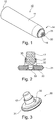
- FIG. 1 shows a prosthetic liner 10 with an elastic body 11, which may be made for example of silicone or other elastomer.
- an elastic body 11 which may be made for example of silicone or other elastomer.
- the application of the prosthetic liner 10 is usually carried out by rolling down the proximal end 12 or everting the proximal end 12, applying a distal end 14 of the prosthetic liner to the distal end of the stump and then rolling on the stump.
- a dimensionally stable end cap 16 is arranged at the distal end 14 of the prosthesis liner 10, for stable and gentle bedding of the stump with respect to the connection of a pneumatic piston 30 on the outside 15, ie the opposite side of the receiving space of the prosthesis liner 10, is used.
- fastening means 17 are arranged, via which it is possible to arrange the pneumatic piston 30 on the end cap 16.
- the pneumatic piston 30 also has a fastening device 37, via which the pneumatic piston 30 can be fixed to the prosthetic liner 10, in particular to the distal end cap 16.
- the underside of the pneumatic piston 30 can be seen, as well as the sealing element 31 can be seen on the outer periphery of the pneumatic piston 30. Due to the arrangement of the sealing element 31 on the outer circumference of the pneumatic piston 30, a tight contact with a cylinder region is possible, so that a pumping effect is effected during a relative movement between the pneumatic piston 30 and the cylinder region.
- the pneumatic piston 30 can be fastened reversibly to the prosthetic liner 10 via the fastening elements 17, 37. This makes it possible to specify different pneumatic piston types on the liner.
- the pneumatic piston 30 may differ in terms of diameter, shape or choice of material.
- the pneumatic piston 30 can also be screwed in place of a pin, whereby it is possible to use a standard liner after the appropriate conversion.
- the coupling of the pneumatic piston 30 with the prosthetic liner 10 is preferably designed as a mechanical coupling, for example as a ball joint 35, it is also possible that an adhesive bond between the components is performed.
- an adhesive bond between the components is performed.
- the end cap 16, which is still deformable to a certain extent, may be made of the material of the prosthetic liner 10 and form a coherent system between the prosthetic liner 10 and the pneumatic piston 30 in a cohesive connection with the pneumatic piston 30.
- the prosthesis liner 10 associated fastening element 17 is integrally formed with the prosthesis liner 10 or materially connected thereto, for example, attached to the end cap 16 or molded.
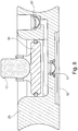
- a fluidic connection 32 in the form of a transverse bore within the pneumatic piston 30 is formed on a projection or shoulder oriented toward the prosthesis liner 10.
- the transverse bore 32 opens into a bore oriented perpendicular to the main surface of the pneumatic piston 30, so that a fluidic connection 32 is present from the ambient atmosphere around the prosthetic liner 10 to the distal end face of the pneumatic piston 30.
- a valve 33 is arranged in the form of a check valve, which allows a passage in the direction of the distal end face of the pneumatic piston 30, a backflow through the fluidic connection 32, however, blocks.
- a plurality of sealing elements 31 may be arranged axially spaced from one another on the outer circumference of the pneumatic piston 30 in order to allow improved guidance in a corresponding cylindrical region 21 of a prosthesis shaft 20.
- FIG. 3 shows a perspective view of FIG. 2 showing the separate configuration of the pneumatic piston 30 on the fastening element 17.
- the fastening element 17 can be reversibly fixed to the prosthetic liner 10, in particular the end cap 16.
- FIG. 4 is shown in a sectional view a detail view in which the pneumatic piston 30 according to FIG. 2 is inserted into a cylinder portion 21 of a receiving part 25.
- the Pneumatic piston 30 closes the cylinder portion 21 in the proximal direction and forms a closed volume 50 with it, which has an outlet valve 51 in the form of a check valve, so that in a relative movement between the receiving element 25 and the pneumatic piston 30 in the direction of the outlet valve 51 in the closed volume 50 compressed air can be pushed out.
- an insertion bevel 26 is incorporated in the receiving part 25, which forms a radius in the illustrated embodiment, so that even with an initially inaccurate positioning of the prosthesis liner 10 in a prosthesis stem, for example during insertion, a true and desired association between the pneumatic piston 30 and the cylinder portion 21 can be realized.
- the receiving part 25 may be attached to the prosthesis stem 20, not shown, and consist of a highly dimensionally stable material, such as a light metal or a fiber-reinforced plastic, which is equipped in the cylinder portion 21 with a smooth surface or has an insert with a favorable friction pairing between the Pneumatic piston 30 and the cylinder portion 21 can be made.
- On the receiving part 25 may be arranged or designed mechanical fasteners or receiving devices for such fasteners, such as threads, holes, undercuts or the like. In principle, it is also possible to attach the receiving part 25 to the prosthesis shaft 20 via gluing, welding or Velcro connections.
- FIG. 6 is a sectional view of a prosthetic liner 10 with the distal end cap 16 and introduced into the prosthesis stem 20 pneumatic piston 30 and the application of the prosthesis liner 10 with the arranged on the outside 15 and attached thereto, movably mounted pneumatic piston 30 shown in conjunction with a prosthesis stem 20.
- the prosthesis stem 20 is substantially simulated to the outer contour of the stump, not shown, and formed in the illustrated embodiment of a dimensionally stable airtight material, such as a fiber-reinforced plastic.
- the user rises with the prosthetic liner 10 and the distal end 14 reversibly attached or integrally formed pneumatic piston 30 through the proximal opening of the prosthesis stem 20 into it.
- the fastening element 17 can be elastic be, for example, a TPE, so that it comes in this case to a deformation of the fastener 17 during insertion of the pneumatic piston 30.
- a volume is clamped in the gap 60, which can be evacuated by a repeated force application in the distal direction and a reverse relief movement by the pneumatic piston 30. Due to the resulting negative pressure, e.g. In a swing phase, a holding force between the pneumatic piston 30 and the prosthesis shaft 20 is also generated, so that the prosthetic liner 10 which adheres to the skin of the stump, via the pneumatic piston 30, to which the prosthetic liner 10 is mechanically coupled , is held on the prosthesis shaft 20 and guided. The main holding force is provided by the negative pressure in the gap 60 between the prosthetic liner and the prosthesis stem.
- FIG. 6 In the sectional view of Fig. 6 also the receiving space 13 for the stump of the prosthesis user is shown.
- the closed volume 50 present between the pneumatic piston 30 and the cylinder area 21 is compressed, the gas contained within the volume 50, usually air, is pushed out and the prosthetic liner 10 can be further displaced in the direction of the distal end 22 of the prosthesis shaft 20, until the pneumatic piston 30 has reached the base area of the cylinder area 21 located at the distal end 22.
- FIG. 7 a variant of the invention is shown, which essentially corresponds to the structure of the device according to FIG. 6 equivalent.
- the prosthetic liner 10 is turned over on the outside about the proximal edge of the prosthesis stem 20 or provided with an outer sleeve which is fixed to the outside of the prosthetic liner 10 and forms a gap into which the prosthesis stem 20 can be inserted, so that a seal also takes place on the outside of the prosthesis stem 20.
- the folded prosthesis liner 10 or the sleeve arranged thereon are designed to be air-tight, the sleeve can be glued to the prosthetic liner 10, welded or pressed and adhesively applied. As a result, the volume enclosed by the prosthetic liner 20 and the prosthesis socket 10 in the intermediate space 60 is securely retained.
- the blocking element 52 is not disposed in the pneumatic piston 30, but within the receiving part 25, in which a fluidic connection from the gap 60 to the closed volume 50 in the form of a channel is available.
- the channel connects the suction side of the pneumatic piston 30 with its pressure side.
- the blocking element 52 is arranged in the form of a check valve which prevents backflow of air from the pressure side to the suction side.
- the receiving part 25 is shown isolated with the pneumatic piston 30, the connecting channel between the gap and the closed volume 50 is blocked via the locking device 52 against flowing out of the closed volume, so that pumping of air from the gap 60 between the prosthesis stem and the Prosthesis liner is possible.
- the arrangement of a check valve 52 in a separate channel on the receiving part 25 has advantages in small dimensions of the pneumatic piston 30, since only a limited space is available in the pneumatic piston.
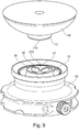
- FIG. 9 shows a perspective view of parts of the prosthesis shaft system with an end cap 16, which is shown without the associated prosthetic liner.
- the fastening device 17 is arranged in the form of a fastening pin.
- the receiving part 25 is shown in isolation, without the integration into a prosthesis stem. Within the receiving part 25 of the pneumatic piston 30 is inserted, protrudes beyond the proximal end of the pneumatic piston 30 from the proximal end of the cylindrical portion of the receiving part 25 out.
- annular safety catch 70 is reversibly arranged, which reduces the diameter of the cylindrical portion within the receiving part 25 and prevents that in an extension movement in the proximal direction of the piston 30 is pulled out of the receiving part 25.
- a proximal end region is formed as a fastening device 37, which has a spherical surface 370 in which four magnets 40 are embedded.
- the magnets 40 are either also provided with a spherical surface and terminate flush with the spherical surface 370 of the fastener 37 or are recessed therein.
- the fastening device 17 on the end cap 16 has a corresponding to the spherical surface 370 shaped contact surface 170, wherein in the fastening device 17 either magnets are also embedded, the fastening device 17 is formed as a magnet or at least of a magnetic, in particular ferromagnetic material, so that the fastening device 17, the magnet 40 within the pneumatic piston 30th can interact.
- the pneumatic piston 30 it is possible for the pneumatic piston 30 to have a convexly curved, spherical surface 370 at the proximal end, and the contact surface 170 to have a concave configuration formed thereon. It is also possible for the magnets or only one magnet to be arranged on the fastening element 17 of the prosthetic liner or of the distal end cap 16, and the pneumatic piston 30 is designed to be ferromagnetic.
- FIG. 10 shows the end cap 16 with the screwed fastener 17 and the spherically shaped contact surface in a sectional view, in the receiving part 25, the cylindrical portion 21 can be seen as well as the arranged thereon pneumatic piston 30 with the radially acting seal 31 and in the pneumatic piston 30 in
- the magnets 40 are advantageously poled in the same direction, so that they ensure a reliable assignment to the mounting pin 17 and the contact surface 170 regardless of the direction of rotation or rotational orientation of the pneumatic piston 30 within the receiving part 25.
- the closed volume 50 is formed, within the piston 30, a valve 33 is provided, from the closed volume 50 branches off a channel with an outlet valve 51, so that the air can escape from the closed volume.
- the pneumatic piston 30 the air can be sucked out of the prosthesis shaft or the prosthetic liner.
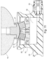
- FIG. 11 shows the embodiment according to FIG. 10 in the joined state.
- the pneumatic piston 30 is in the upper position, the magnets 40 pull the fastener 17 to the piston 30 and the contact surface 170 is fully applied to the spherical surface 370 of the piston-side fastening device 37 at.
- FIG. 12 shows the arrangement according to FIG. 11 with the mounted pull-out protection 70, which is arranged in the receiving part 25, for example screwed.
- the upper edge of the pneumatic piston 30 abuts against the lower edge of the safety catch, as is the case during a swing phase, for example.
- the end cap 16 is slightly tilted to the vertical axis so that the contact surface 170 is displaced on the spherical surface 370 without losing contact. Due to the curved surfaces, it is possible that a relative movement, in particular a tilt about three pivot axes, which intersect at the center of the spherical surface 370, without problems is possible.
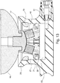
- FIG. 13 is the arrangement according to FIG. 11 together with the safety catch 70 shown in the middle, lowered position, the piston is displaced downwards towards the distal end of the cylindrical portion 21, the closed volume 50 is reduced and the air has been forced out of the outlet valve 51.
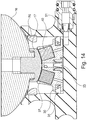
- FIG. 14 shows the embodiment according to FIG. 13 in the distal end position, the piston 30 is almost in contact with the cylinder bottom, the closed volume 50 is minimal.
- the end cap 16 is almost in contact with the proximal end of the receiving part 25th
- the maximum piston stroke of the pneumatic piston 30 can be adjusted. If the pneumatic piston 30 is relocated in the direction of the safety catch 70 during a discharge, for example during the swing phase, air flows either from the prosthesis stem 20 or from the prosthetic liner 10 through the valve 30 into the increasing, closed volume 50 Movement, for example during the stance phase, the closed volume 50 is reduced again and pushed out the sucked air.
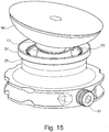
- FIG. 15 shows the arrangement according to FIG. 12 in an oblique view, the end cap 16 is tilted to the vertical axis, the pullout guard 70 is annular around the cylindrical portion 21 of the receiving part 25 and prevents that at a separation of the frictional connection between the prosthetic liner 10 and the pneumatic piston 30 of the pneumatic piston 30 from the receiving part 25 is moved out.
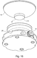
- FIG. 16 shows a bottom view of the end cap 16 with the convex, spherical contact surface 170 and the bottom of the receiving part 25 with the outlet valve 51st
- FIG. 17 shows the assignment according to FIG. 16 in a perspective oblique top view.
- the at least partially spherical surface 370 of the proximal end of the pneumatic piston 30 in the region of the fastening device 37 can be seen as well as the reset magnets 40.
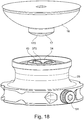
- FIG. 18 shows the assignment according to FIG. 17 in a diagonal side view.
- FIG. 19 shows the receiving part 25 in a perspective detailed view. It can be seen that the pull-out safety device 70 has two mutually opposite recesses 75 into which a tool can engage in order to fix the safety catch 70 to the receiving part 25 in the region of the cylinder wall. In addition to a screwing into a thread which is formed in the cylindrical portion, wherein the pull-out protection 70 has an external thread, the pull-out protection 70 can also be screwed or fastened via separate screws or fastening means on the receiving part 25 and held in a form-fitting manner.
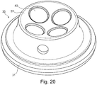
- FIG. 20 shows the pneumatic piston 30 in a single representation with the four magnets arranged therein, the fastening means 37 with the spherical surface 370 and the radially arranged sealing element 31 in the form of a sealing ring.
- FIG. 21 shows the pneumatic piston 30 in a bottom view with the valve 33, the allows air to flow into the closed volume 50, but prevents backflow.
- the valve 33 may be formed as a hose valve or flutter valve and serves as a check valve.
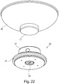
- FIG. 22 shows the assignment of the end cap 16 with the fastening element 17 as a mounting piston and the pneumatic piston 30 obliquely from below.
- FIG. 23 shows the pneumatic piston 30 with the fastening element 37, the sealing ring 31 before joining with the distal end cap 16.
Landscapes
- Health & Medical Sciences (AREA)
- Cardiology (AREA)
- Oral & Maxillofacial Surgery (AREA)
- Transplantation (AREA)
- Engineering & Computer Science (AREA)
- Biomedical Technology (AREA)
- Heart & Thoracic Surgery (AREA)
- Vascular Medicine (AREA)
- Life Sciences & Earth Sciences (AREA)
- Animal Behavior & Ethology (AREA)
- General Health & Medical Sciences (AREA)
- Public Health (AREA)
- Veterinary Medicine (AREA)
- Prostheses (AREA)
- Dental Prosthetics (AREA)
Description
Die Erfindung betrifft einen Prothesenliner zur Anlage an einen Stumpf, mit einem elastischen Grundkörper, der eine proximale Öffnung zum Einführen des Stumpfes in einen Aufnahmeraum und ein distales Ende aufweist, sowie ein Prothesenschaftsystem mit einem solchen Prothesenliner und einem Prothesenschaft.The invention relates to a prosthetic liner for abutment with a stump, having an elastic base body having a proximal opening for insertion of the stump in a receiving space and a distal end, and a prosthesis shank system having such a prosthetic liner and a prosthesis stem.
Prothesen dienen zum Ersetzen der Funktion und gegebenenfalls der optischen Erscheinung einer fehlenden Gliedmaße und werden an dem Körper des Patienten festgelegt. Zur Festlegung der Prothese sind vielfältige Möglichkeiten bekannt. Eine weit verbreitete Möglichkeit zur Festlegung von Prothesen an den Extremitäten ist die Anordnung an einem verbliebenen Teil der Gliedmaße, dem sogenannten Stumpf. Der Stumpf wird von einem Prothesenschaft umfasst, der in der Regel formstabil ist. An dem proximalen Ende des Schafts ist eine Einführöffnung ausgebildet, an dem distalen Ende des Schaftes ist zumindest eine Befestigungseinrichtung vorgesehen, an der weitere Prothesenkomponenten angeordnet werden können, beispielsweise Gelenke oder funktionale Einheiten wie Prothesenfüße oder Prothesenhände. Um eine gute Passform zu erreichen, wird ein Modell des Stumpfes angefertigt und der Schaft an die Kontur des Stumpfmodells angepasst. Um Volumenschwankungen ausgleichen zu können, kann vorgesehen sein, dass der Schaft enger gefertigt wird als das abgeformte Stumpfmodell.Prostheses serve to replace the function and, if necessary, the visual appearance of a missing limb and are fixed to the body of the patient. To determine the prosthesis many possibilities are known. A widespread possibility for the determination of prostheses on the extremities is the arrangement of a remaining part of the limb, the so-called stump. The stump is comprised of a prosthesis stem that is usually dimensionally stable. At the proximal end of the shaft an insertion opening is formed, at the distal end of the shaft at least one fastening device is provided on which further prosthesis components can be arranged, for example joints or functional units such as prosthetic feet or prosthetic hands. In order to achieve a good fit, a model of the stump is made and adapted the shaft to the contour of the stump model. In order to compensate for volume fluctuations, it can be provided that the shaft is made narrower than the molded stump model.
Um den Tragekomfort zu erhöhen kann es vorgesehen sein, dass zwischen dem Prothesenschaft und dem Stumpf ein sogenannter Prothesenliner angeordnet ist. Der Prothesenliner besteht in der Regel aus einem geschlossenen Grundkörper mit einer proximalen Öffnung und wird strumpfartig über den Stumpf gezogen. Das elastische Material haftet auf der Stumpfoberfläche und stellt die Verbindung zwischen dem Stumpf und dem Prothesenschaft her. Zur Befestigung des Prothesenliners an dem Prothesenschaft können mechanische Verriegelungselemente am distalen Ende des Prothesenliners und korrespondierende Verriegelungseinrichtungen am distalen Ende des Prothesenschaftes vorgesehen sein, die den Prothesenliner mit dem Prothesenschaft nach dem Einsteigen in den Prothesenschaft formschlüssig verriegeln. Über eine Entriegelungseinrichtung kann die Befestigung des Prothesenliners an dem Prothesenschaft aufgehoben werden.In order to increase the wearing comfort, it can be provided that a so-called prosthesis liner is arranged between the prosthesis socket and the stump. The prosthetic liner usually consists of a closed base body with a proximal opening and is pulled like a stocking over the stump. The elastic material adheres to the stump surface and establishes the connection between the stump and the prosthesis stem. For securing the prosthetic liner to the prosthesis stem, mechanical locking elements may be provided at the distal end of the prosthesis liner and corresponding locking means at the distal end of the prosthesis stem which positively lock the prosthetic liner with the prosthesis stem after entering the prosthesis stem. About an unlocking device the attachment of the prosthetic liner to the prosthesis stem can be canceled.
Eine weitere Möglichkeit zur Befestigung eines Prothesenschaftes an einem Stumpf besteht in der sogenannten Saugschaftlinertechnologie, bei der der Prothesenschaft luftdicht gegenüber dem Prothesenliner abgedichtet wird und aus dem Zwischenraum zwischen dem Prothesenliner und dem Prothesenschaft die darin vorhandene Luft abgesaugt oder herausgedrückt wird. Ein Rückströmen wird über ein Rückschlagventil verhindert. Hierzu ist es notwendig, den Prothesenschaft luftdicht auszugestalten und eine großflächige Abdichtung gegenüber dem Prothesenliner sicherzustellen.Another way to attach a prosthesis stem to a stump is the so-called Saugschaftlinertechnologie, in which the prosthesis stem is sealed airtight to the prosthesis liner and sucked out of the space between the prosthetic liner and the prosthesis stem, the air present therein or pushed out. Backflow is prevented by a check valve. For this purpose, it is necessary to design the prosthesis stem airtight and to ensure a large-area seal against the prosthetic liner.
Die
Die
Die
Die
Die
Die
Die
Die
Die
Aufgabe der vorliegenden Erfindung ist es, einen Prothesenliner und ein Prothesenschaftsystem bereitzustellen, mit dem eine sichere Befestigung der Prothese an dem Liner bei passiven Vakuumschäften möglich ist und ein verbessertes Haltegefühl sowie ein verbesserter Tragekomfort für den Anwender bereitgestellt werden kann.The object of the present invention is to provide a prosthetic liner and a prosthesis shaft system, with which a secure attachment of the prosthesis to the liner in passive vacuum stems is possible and an improved feeling and improved comfort for the user can be provided.
Erfindungsgemäß wird diese Aufgabe durch einen Prothesenliner mit den Merkmalen des Hauptanspruchs und ein Prothesenschaftsystem mit den Merkmalen des nebengeordneten Anspruchs gelöst. Vorteilhafte Ausgestaltungen und Weiterbildungen der Erfindung sind in den Unteransprüchen, den Figuren und der Beschreibung offenbart.According to the invention this object is achieved by a prosthetic liner with the features of the main claim and a prosthesis shaft system having the features of the independent claim. Advantageous embodiments and further developments of the invention are disclosed in the subclaims, the figures and the description.
Der Prothesenliner zur Anlage an einen Stumpf, mit einem elastischen Grundkörper, der eine Proximalöffnung zum Einführen des Stumpfes in einen Aufnahmeraum und distales Ende aufweist, sieht vor, dass an der Außenseite des Prothesenliners ein Pneumatikkolben angeordnet ist.The prosthetic liner for abutment with a stump having an elastic body having a proximal opening for insertion of the stump into a receiving space and distal end provides that a pneumatic piston is disposed on the outside of the prosthetic liner.
Bei einem passiven Vakuumsystem, also einem System, bei dem ein Vakuum zwischen einem Prothesenliner und einem Prothesenschaft durch den Prothesenträger selbst und die Relativbewegung des Prothesenliners relativ zum Prothesenschaft erzeugt wird, wird ein Unterdruck im Schaftinnenraum in der Schwungphase erzeugt, in der die Protheseneinrichtung aufgrund der Fliehkräfte von dem Stumpf wegbewegt wird. Durch den Unterdruck im Schaftinnenraum während der Schwungphase wird eine Haltekraft erzeugt, die für die befestigende Wirkung des Prothesenliners in dem Prothesenschaft verantwortlich ist. Diese Bewegung kann von Anwendern als unangenehm empfunden werden, weil das Abheben des Prothesenschaftes und des Liners zu einem Gefühl von Instabilität und losem Sitz führen kann. Die Luft aus dem Zwischenraum zwischen Prothesenliner und Prothesenschaft wird durch den Pneumatikkolben evakuiert, was zu einer verbesserten Haltekraft führt. Es entsteht ein selbstregulierendes System, welches darauf ausgelegt ist, den optimalen Halt zwischen dem Prothesenschaft und dem Prothesenliner zu gewährleisten. Der Pneumatikkolben ermöglicht eine präzise Führung des distalen Endes des Liners bei effektiver Pumpwirkung aufgrund der vereinfachten Abdichtbarkeit des durch den Pneumatikkolben abgeschlossenen Volumens.In a passive vacuum system, ie a system in which a vacuum between a prosthetic liner and a prosthesis stem is generated by the prosthesis wearer itself and the relative movement of the prosthesis liner relative to the prosthesis stem, a negative pressure in the shaft interior is generated in the swing phase, in which the prosthetic device due Centrifugal forces is moved away from the stump. By the negative pressure in the shaft interior during the swing phase, a holding force is generated, which is responsible for the fastening effect of the prosthetic liner in the prosthesis stem. This movement may be perceived as unpleasant by users because lifting the prosthetic stem and liner may result in a sense of instability and loose fit. The air from the gap between prosthetic liner and prosthesis stem is evacuated by the pneumatic piston, resulting in an improved holding force. The result is a self-regulating system which is designed to ensure the optimum hold between the prosthesis socket and the prosthetic liner. The pneumatic piston allows precise guidance of the distal end of the liner with effective pump action due to the simplified sealability of the closed by the pneumatic piston Volume.
Eine Weiterbildung der Erfindung sieht vor, dass der Pneumatikkolben ein Sperrelement aufweist, das ein Rückströmen von Luft in Richtung auf den Prothesenliner verhindert. Durch die Anordnung eines Sperrelementes, z.B. eines Ventils oder einer umlaufenden Sperrlippe, in oder an einem am distalen Ende des Prothesenliners angeordneten Pneumatikkolben ist es möglich, die Relativbewegung zwischen dem Prothesenliner und dem Prothesenschaft dazu zu nutzen, den Unterdruck innerhalb des Prothesenschaftes zu erhöhen und dadurch das Abheben des Prothesenliners von der Innenwand des Prothesenschaftes zu reduzieren. Die Luft aus dem Zwischenraum zwischen Prothesenliner und Prothesenschaft wird durch den Kolben hindurch evakuiert, was zu einem kompakten Aufbau führt, bei dem für die Evakuierung wesentlichen Komponenten in dem Pneumatikkolben integriert sind..A development of the invention provides that the pneumatic piston has a blocking element which prevents a backflow of air in the direction of the prosthetic liner. By the arrangement of a blocking element, e.g. a valve or a circumferential blocking lip, in or on a pneumatic piston arranged at the distal end of the prosthesis liner, it is possible to use the relative movement between the prosthetic liner and the prosthesis stem to increase the negative pressure within the prosthesis stem and thereby lift the prosthetic liner from the inner wall to reduce the prosthetic stem. The air from the gap between prosthetic liner and prosthesis stem is evacuated through the piston, resulting in a compact design in which essential components for evacuation are integrated in the pneumatic piston.
Der Pneumatikkolben kann als ein separates Bauteil ausgebildet und an dem Prothesenliner befestigt sein, insbesondere kann der jeweilige Pneumatikkolben reversibel an dem distalen Ende oder im distalen Endbereich des Prothesenliners befestigt sein. Durch eine reversible Befestigung oder Befestigungsmöglichkeit an dem Prothesenliner ist es möglich, unterschiedlich große Pneumatikkolben an dem Liner zu befestigen, um eine Anpassung an die jeweils benötigte Haltekraft oder das benötigte Pumpvolumen ermöglichen zu können. Zur reversiblen Befestigung des Pneumatikkolbens an dem Prothesenliner ist zumindest eine Befestigungseinrichtung an dem Prothesenliner und korrespondierend an dem Pneumatikkolben ausgebildet. Die Befestigungseinrichtung kann beispielsweise ein Schraubsystem, ein Klicksystem mit einer Kugelkopflagerung, eine formschlüssige Verriegelung über Klettverschlüsse oder ein Zapfensystem mit korrespondierender Aufnahme und formschlüssiger Verriegelung ausgebildet sein.The pneumatic piston can be designed as a separate component and fastened to the prosthetic liner, in particular the respective pneumatic piston can be reversibly fastened to the distal end or in the distal end region of the prosthesis liner. By a reversible attachment or attachment to the prosthetic liner, it is possible to attach different sized pneumatic piston to the liner to allow adaptation to the particular holding force required or the required pumping volume. For reversible attachment of the pneumatic piston to the prosthetic liner, at least one attachment device is formed on the prosthetic liner and corresponding to the pneumatic piston. The fastening device may be formed, for example, a screw system, a click system with a ball head bearing, a positive locking via Velcro fasteners or a pin system with a corresponding receptacle and positive locking.
Neben der reversiblen Befestigung des Pneumatikkolbens an dem Liner ist es möglich, diesen auch einstückig mit dem Liner auszubilden oder stoffschlüssig daran festzulegen. Dazu kann der Pneumatikkolben beispielsweise über einen elastischen Schaft an dem Prothesenliner befestigt sein, so dass geringe Fluchtungsfehler zwischen dem Pneumatikkolben und der prothesenschaftseitigen Aufnahme ausgeglichen werden können. Durch eine einteilige Ausgestaltung ist es möglich, auf eine separate Montage und ein separates Kopplungselement zu verzichten. Bei einer elastischen Anbindung des Pneumatikkolbens an dem Prothesenliner wird eine Zusammenführung des Prothesenliners mit dem Prothesenschaft erleichtert, da leichte Schiefstellungen des Pneumatikkolbens durch die Materialelastizität ausgeglichen werden können.In addition to the reversible attachment of the pneumatic piston to the liner, it is also possible to form it integrally with the liner or firmly bonded thereto. For this purpose, the pneumatic piston may be fastened to the prosthesis liner, for example via an elastic shaft, so that slight misalignment between the pneumatic piston and the prosthesis side receptacle can be compensated. By a one-piece design, it is possible to have a separate assembly and dispense with a separate coupling element. In an elastic connection of the pneumatic piston to the prosthetic liner, a merging of the prosthetic liner is facilitated with the prosthesis stem, since slight misalignments of the pneumatic piston can be compensated by the material elasticity.
Das dem Pneumatikkolben zugeordnete Sperrelement als Ventil in oder an dem Pneumatikkolben oder als Sperrlippe ausgebildet sein, die ähnlich einer Luftpumpe funktioniert und bei einer Ansaugbewegung Luft in das geschlossene Volumen einströmen lässt, bei einer Ausstoßbewegung sich an den Zylinderbereich anlegt und dadurch eine Abdichtung bewirkt.The locking element associated with the pneumatic piston may be designed as a valve in or on the pneumatic piston or as a blocking lip which functions similarly to an air pump and allows air to flow into the closed volume during a suction movement, applies to the cylinder area during an ejection movement and thereby effects a seal.
Um eine sichere Befestigung des Pneumatikkolbens an dem Prothesenliner gewährleisten zu können und darüber hinaus eine ausreichende Stabilität und Kraftverteilung von dem distalen Ende des Prothesenliners auf den Stumpf zu ermöglichen, ist in einer Weiterbildung der Erfindung am distalen Ende eine formstabile Abschlusskappe vorgesehen, an der der Pneumatikkolben festgelegt wird. Die Festlegung kann über die oben beschriebenen Befestigungseinrichtungen erfolgen. Grundsätzlich ist es auch möglich, dass der Pneumatikkolben an dem distalen Ende des Prothesenliners oder der Abschlusskappe angeformt ist, so dass sich eine sehr kompakte Bauweise ergibt.In order to ensure a secure attachment of the pneumatic piston to the prosthetic liner and also to allow sufficient stability and force distribution from the distal end of the prosthetic liner on the stump, a rigid end cap is provided in an embodiment of the invention at the distal end, on which the pneumatic piston is determined. The determination can be made via the fastening devices described above. In principle, it is also possible that the pneumatic piston is formed on the distal end of the prosthetic liner or the end cap, so that results in a very compact design.
Der Pneumatikkolben kann zumindest ein umlaufendes Dichtelement aufweisen, insbesondere einen O-Ring, über das das Volumen zwischen dem Pneumatikkolben und dem Zylinderbereich des Prothesenschaftes abdichtbar ist. Grundsätzlich ist es auch möglich und vorgesehen, dass der Kolben auch ohne Dichtelement in dem Zylinderbereich arbeiten kann, wenn die Passgenauigkeit ausreichend hoch ist.The pneumatic piston can have at least one circumferential sealing element, in particular an O-ring, via which the volume between the pneumatic piston and the cylinder region of the prosthesis shaft can be sealed off. In principle, it is also possible and provided that the piston can work without sealing element in the cylinder area, if the fit accuracy is sufficiently high.
Eine Weiterbildung der Erfindung sieht vor, dass der Pneumatikkolben beweglich an dem Prothesenliner, z.B. über ein Kugelgelenk oder ein Elastomerelement, befestigt ist. Die bewegliche Befestigung kann dabei unmittelbar an dem Prothesenliner oder an einer daran angeordneten Abschlusskappe erfolgen. Durch ein Kugelgelenk ist es möglich, dass der Pneumatikkolben stets senkrecht innerhalb eines korrespondierenden Zylinderbereiches im Prothesenschaft bewegt werden kann, ohne dass eine Verkantung des Pneumatikkolbens innerhalb des Zylinderbereiches erfolgt. Über das Kugelgelenk kann gleichzeitig eine reversible Verbindung zwischen dem Pneumatikkolben und dem Prothesenliner erfolgen, indem das prothesenlinerseitige Befestigungselement als Kugelkopf ausgebildet ist, auf den ein mit einer entsprechenden Aufnahme versehener Pneumatikkolben aufgeclipst wird. Neben einer Lagerung mittels eines Kugelgelenkes, das eine Verdrehung um einen Drehpunkt in der Regel ohne Rückstellkräfte ermöglicht, ist eine elastische Anbindung des Pneumatikkolbens an dem Prothesenliner möglich, beispielsweise über einen elastischen Steg, Zapfen, Bolzen oder dergleichen. Durch die elastische Anbindung ist neben einer Relativverlagerbarkeit des Pneumatikkolbens zu dem Prothesenliner auch eine Führung und Zentrierung innerhalb des Prothesenschaftes gegeben.A development of the invention provides that the pneumatic piston is movably attached to the prosthetic liner, for example via a ball joint or an elastomeric element. The movable attachment can be carried out directly on the prosthetic liner or on an end cap arranged thereon. Through a ball joint, it is possible that the pneumatic piston can always be moved vertically within a corresponding cylinder area in the prosthesis shaft, without causing tilting of the pneumatic piston within the cylinder area. About the ball joint At the same time, a reversible connection between the pneumatic piston and the prosthetic liner can take place in that the prosthesis-side fastening element is designed as a ball head, onto which a pneumatic piston provided with a corresponding receptacle is clipped. In addition to a storage by means of a ball joint, which allows a rotation about a pivot point usually without restoring forces, an elastic connection of the pneumatic piston to the prosthetic liner is possible, for example via an elastic web, pins, bolts or the like. The elastic connection, in addition to a Relativverlagerbarkeit of the pneumatic piston to the prosthesis liner also given a guide and centering within the prosthesis stem.
Eine Weiterbildung der Erfindung sieht vor, dass der Pneumatikkolben über zumindest einen Magneten an dem Prothesenliner befestigt ist. Über die magnetische, also kraftschlüssige Befestigung des Pneumatikkolbens an dem Prothesenliner, beispielsweise an einem Zapfen einer Abschlusskappe ist es möglich, unterschiedliche Prothesenliner einfach an dem Pneumatikkolben anzuschließen, so dass eine standardisierte Pneumatikeinheit mit unterschiedlichen Prothesenlinern oder umgekehrt gekoppelt werden kann. Auch ist es möglich, durch die magnetische Kopplung eine vergleichsweise einfache Auswechslung einzelner Komponenten vorzunehmen.A further development of the invention provides that the pneumatic piston is fastened to the prosthetic liner via at least one magnet. About the magnetic, ie non-positive attachment of the pneumatic piston to the prosthetic liner, for example on a pin of a cap, it is possible to connect different prosthetic liner simply on the pneumatic piston, so that a standardized pneumatic unit with different prosthetic liners or vice versa can be coupled. It is also possible to carry out a comparatively simple replacement of individual components by the magnetic coupling.
Der Pneumatikkolben ist in einer Ausgestaltung der Erfindung über zumindest einen Magneten konnektierbar in einem Prothesenschaftsystem aus dem Prothesenliner, insbesondere wie er oben beschrieben wurde, und einem Prothesenschaft integriert oder integrierbar.In one embodiment of the invention, the pneumatic piston can be connected via at least one magnet in a prosthesis shaft system made from the prosthetic liner, in particular as described above, and integrated or integrated into a prosthesis shaft.
Um bei einer magnetischen Anbindung des Pneumatikkolbens an dem Prothesenliner eine dem Kugelgelenk ähnliche Verschieblichkeit zuzulassen, so dass der Pneumatikkolben selbst stets gradlinig in dem Aufnahmeteil, insbesondere in dem zylindrischen Bereich des Aufnahmeteils geführt werden kann, ist an dem Pneumatikkolben zumindest bereichsweise eine sphärische Oberfläche vorgesehen, die entweder konvex oder konkav ausgebildet sein kann. Über die sphärische Oberfläche ist eine Verlagerbarkeit und gewisse Verschiebbarkeit aufgrund der magnetischen Anbindung möglich, so dass Drehkräfte nicht unmittelbar auf den Pneumatikkolben übertragen werden, so dass eine Verkantung nicht nur oder in Extremsituationen stattfinden kann.In order to permit a ball joint similar mobility at a magnetic connection of the pneumatic piston to the prosthetic liner, so that the pneumatic piston itself can always be guided straight in the receiving part, in particular in the cylindrical portion of the receiving part, a spherical surface is at least partially provided on the pneumatic piston, which can be either convex or concave. Due to the magnetic connection, a displaceability and a certain displaceability on the spherical surface are possible, so that rotational forces are not transmitted directly to the pneumatic piston that canting can not happen only or in extreme situations.
An dem Prothesenliner kann ein Befestigungselement angeordnet sein, über das der Pneumatikkolben an dem Prothesenliner befestigt wird und dass eine zu einer zumindest bereichsweise sphärischen Oberfläche des Pneumatikkolbens korrespondierend ausgebildete Kontaktoberfläche ausweist. Durch die konvex ausgebildete Kontaktoberfläche bei einer konkav ausgebildeten sphärischen Oberfläche des Pneumatikkolbens oder umgekehrt ist es möglich, eine kugelgelenkartige Bewegung des Pneumatikkolbens um das Befestigungselement auszuführen, so dass eine Relativverlagerung des Prothesenliners zu dem Pneumatikkolben hinsichtlich der möglichen Drehachsen stets gegeben ist.A fastening element can be arranged on the prosthetic liner via which the pneumatic piston is fastened to the prosthetic liner and in that a contact surface corresponding to a surface of the pneumatic piston which is at least partially spherical has a corresponding contact surface. Due to the convex contact surface with a concave spherical surface of the pneumatic piston or vice versa, it is possible to perform a ball-joint-like movement of the pneumatic piston to the fastener, so that a relative displacement of the prosthesis liner is always given to the pneumatic piston with respect to the possible axes of rotation.
Die Verbindung zwischen dem Prothesenliner und dem Pneumatikkolben kann beim Einsteigen des Nutzers in den Prothesenschaft erfolgen, so dass sobald der Prothesennutzer in den Prothesenschaft einsteigt, der Prothesenliner oder das Befestigungselement die Kontaktfläche in den Kontakt mit den Magneten an oder in dem Pneumatikkolben bringt. Selbst wenn der Kolben im Ruhezustand in der unteren Position befindlich ist, reichen in der Regel die Magnetkräfte aus, um den Kolben wieder in die obere Position zu bewegen. In der Regel befindet sich der Pneumatikkolben jedoch in der oberen Position, da dort der Kolben beim Ausstieg aus dem Prothesenschaft befindlich ist. Eine Trennung des Prothesenliners von dem Pneumatikkolben kann bei einem Ausstieg des Prothesennutzers aus dem Prothesenschaft leicht durch eine Auszugsbewegung erfolgen, die lediglich eine Kraft aufbringen muss, die größer als die der Haltemagnete in dem Pneumatikkolben oder in dem Befestigungselement ausgeübt wird.The connection between the prosthetic liner and the pneumatic piston can occur when the user enters the prosthesis socket, so that as soon as the prosthesis user enters the prosthesis socket, the prosthetic liner or the fastening element brings the contact surface into contact with the magnets on or in the pneumatic piston. Even if the piston is in the idle state in the lower position, the magnetic forces are usually sufficient to move the piston back to the upper position. As a rule, however, the pneumatic piston is in the upper position, since there the piston is located when leaving the prosthesis shaft. A separation of the prosthetic liner from the pneumatic piston can be done easily by a withdrawal movement in an exit of the prosthesis user from the prosthesis stem, which only has to apply a force that is greater than that of the holding magnets in the pneumatic piston or in the fastener exerted.
Das Prothesenschaftsystem mit einem Prothesenliner zur Anlage an einen Stumpf, mit einem elastischen Grundkörper, der eine proximale Öffnung zum Einführen des Stumpfes in einen Aufnahmeraum und ein distales Ende aufweist, und einem Prothesenschaft, der mit dem Prothesenliner einen Zwischenraum ausbildet, sieht vor, dass an der Außenseite des Prothesenliners zumindest ein Pneumatikkolben angeordnet ist und dass der Prothesenschaft einen zu dem Pneumatikkolben korrespondierenden Zylinderbereich aufweist, der zur Aufnahme des Pneumatikkolbens ausgebildet ist und in dem im gekoppelten Zustand des Prothesenliners mit dem Prothesenschaft ein geschlossenes Volumen ausgebildet ist, das mit zumindest einem Sperrelement gekoppelt ist, das ein Rückströmen von Luft in den Zwischenraum verhindert. Der Prothesenliner kann wie er oben beschrieben wurde ausgestaltet sein oder auch ohne integriertes Ventil oder integrierte Sperrlippe bei einer entsprechenden Ausgestaltung des Zylinderbereiches arbeiten. Der korrespondierende Zylinderbereich ist so ausgebildet, dass der Pneumatikkolben an der Innenseite des Prothesenliners entlang eines Dichtelementes entlang gleiten kann, um Luft aus dem geschlossenen Volumen herauszudrücken.The prosthetic socket system with a prosthetic liner for abutment with a stump having a resilient body having a proximal opening for inserting the stump into a receiving space and a distal end and a prosthesis stem forming a gap with the prosthetic liner provides for at least one pneumatic piston is arranged on the outside of the prosthetic liner, and that the prosthesis shaft has a cylinder region which corresponds to the pneumatic piston and which is designed to receive the pneumatic piston and in that in the coupled state of the prosthetic liner with the prosthesis stem a closed volume is formed, which is coupled to at least one blocking element which prevents a backflow of air into the intermediate space. The prosthetic liner can be designed as described above or also work without an integrated valve or integrated blocking lip with a corresponding configuration of the cylinder region. The corresponding cylinder region is designed such that the pneumatic piston can slide along the inside of the prosthetic liner along a sealing element in order to push air out of the closed volume.
Erfindungsgemäß ist vorgesehen, dass der Pneumatikkolben zusammen mit dem korrespondierenden Zylinderbereich an dem Prothesenschaft ein geschlossenes Volumen ausbildet, das durch ein Sperrelement, insbesondere ein Rückschlagventil, bei einer Volumenvergrößerung, beispielsweise während der Schwungphase, Luft aus dem Bereich zwischen dem Prothesenschaft und dem Prothesenliner ansaugt und während der Standphase, wenn eine Axialbelastung in Richtung auf das distale Ende des Prothesenschaftes erfolgt, durch ein gleichgerichtetes Rückschlagventil, beispielsweise an dem dem Pneumatikkolben gegenüberliegenden Ende des zylindrischen Bereiches, wieder ausgestoßen wird. Das geschlossene Volumen, das aufgrund der Relativverlagerung zwischen dem zylindrischen Bereich und dem Pneumatikkolben variabel ist, stellt das Pumpvolumen dar, das bei einem vollständigen Hub dem maximalen Ausstoßvolumen entspricht. Je größer der Durchmesser des Pneumatikkolbens und je größer der mögliche Hub, desto größer ist das Pumpvolumen und damit der je Hub erreichbare Unterdruck zwischen dem Prothesenschaft und dem Prothesenliner.According to the invention, the pneumatic piston together with the corresponding cylinder area forms a closed volume on the prosthesis shaft, which sucks air from the area between the prosthesis shaft and the prosthetic liner through a blocking element, in particular a check valve, during an increase in volume, for example during the swing phase during the stance phase, when an axial load is applied in the direction of the distal end of the prosthesis stem, is ejected again by a rectified check valve, for example, at the opposite end of the cylindrical portion of the pneumatic piston. The closed volume, which is variable due to the relative displacement between the cylindrical portion and the pneumatic piston, represents the pumping volume, which corresponds to the maximum discharge volume at a complete stroke. The larger the diameter of the pneumatic piston and the larger the possible stroke, the larger the pumping volume and thus the achievable per stroke vacuum between the prosthesis shaft and the prosthetic liner.
Innerhalb des Volumens kann zumindest eine Sperreinrichtung oder zumindest eine strömungstechnische Verbindung zu einer Sperreinrichtung vorhanden sein, die ein Ausströmen von Luft ermöglicht und ein Rückströmen verhindert. Dies ist beispielsweise durch ein Rückschlagventil möglich, das gegebenenfalls auch geöffnet werden kann, um den Unterdruck zu reduzieren und die Haltekraft zu verringern. Durch das Anordnen einer Sperreinrichtung ist ein nahezu geräuschloses Evakuieren möglich, darüber hinaus kann derjenige Ort definiert werden, an dem die Luft aus dem Volumen herausgedrückt wird. Die Sperreinrichtung oder Sperreinrichtungen ermöglichen ein Absaugen der Luft aus dem Zwischenraum zwischen dem Prothesenliner und dem Prothesenschaft und verhindern ein Rückströmen von Luft aus der Umgebung durch das geschlossene Volumen in den Zwischenraum.Within the volume, at least one blocking device or at least one fluidic connection to a blocking device can be present, which allows air to escape and prevents backflow. This is possible for example by a check valve, which can also be opened if necessary, to reduce the negative pressure and to reduce the holding force. By arranging a locking device, an almost noiseless evacuation is possible, moreover, the place can be defined, at which the air is forced out of the volume. The locking device or locking devices allow a Extracting the air from the gap between the prosthetic liner and the prosthesis stem and prevent backflow of air from the environment through the closed volume in the gap.
Das geschlossene Volumen und/oder der Zwischenraum können mit einer Belüftungseinrichtung zum Einleiten von Luft in strömungstechnischer Verbindung stehen, um den Unterdruck in dem geschlossenen Volumen oder Zwischenraum aufzuheben und Umgebungsluft in das geschlossene Volumen und/oder den Zwischenraum zwischen dem Prothesenschaft und dem Prothesenliner einleiten zu können, damit der Prothesenliner aus dem Prothesenschaft entfernt werden kann. Die Belüftungseinrichtung weist einen Zugang zu dem geschlossenen Volumen und/oder direkt zu dem Zwischenraum von Prothesenliner und Prothesenschaft auf, um ein Lösen der Verbindung zu ermöglichen. Alternativ zu der Verwendung einer Belüftungseinrichtung kann der Zwischenraum dadurch belüftet werden, dass eine Dichtmanschette, die als proximale Abdichtung eingesetzt wird, entfernt wird. Sofern eine Dichtung in dem Schaft angeordnet oder an dem Liner angeordnet ist, ist eine separate Belüftungseinrichtung notwendig.The closed volume and / or gap may be in fluid communication with a vent for introducing air to relieve the negative pressure in the closed volume or space and introduce ambient air into the closed volume and / or space between the prosthesis stem and the prosthetic liner so that the prosthetic liner can be removed from the prosthesis socket. The aerator has access to the closed volume and / or directly to the gap of the prosthetic liner and prosthesis stem to facilitate disconnection. As an alternative to using a ventilator, the gap may be vented by removing a sealing collar used as a proximal seal. If a seal is arranged in the shaft or arranged on the liner, a separate ventilation device is necessary.
An dem proximalen Ende des Zylinderbereiches kann eine Einführschräge vorgesehen sein, die ein Einführen des Pneumatikkolbens in den Zylinderbereich erleichtert, so dass die korrekte Zuordnung zwischen dem Stumpf mit Prothesenliner und dem Prothesenschaft einfach hergestellt werden kann. Über die Einführschräge wird der Pneumatikkolben automatisch zu dem Zylinderbereich geführt und sorgt dort für eine Zentrierung bzw. Orientierung des Prothesenliners innerhalb des Prothesenschaftes.At the proximal end of the cylinder area, an insertion bevel may be provided, which facilitates insertion of the pneumatic piston into the cylinder area, so that the correct association between the die with prosthetic liner and the prosthesis socket can be easily established. About the insertion of the pneumatic piston is automatically guided to the cylinder area and there ensures a centering or orientation of the prosthetic liner within the prosthesis shaft.
An dem proximalen Ende des Zylinderbereiches kann eine Auszugssicherung für den Pneumatikkolben angeordnet sein, so dass verhindert wird, dass der Pneumatikkolben bei einem Ausstieg aus dem Prothesenschaft aus dem zylindrischen Bereich herausgezogen wird. Die Auszugssicherung kann mechanisch, insbesondere formschlüssig an dem Aufnahmeteil angeordnet sein, beispielsweise eingeschraubt, eingeklemmt oder eingeclipst. Vorteilhafterweise ist eine umlaufende Ausgestaltung der Auszugssicherung durch einen angeschraubten oder anderweitig festgelegten Ring vorgesehen. Nachfolgend werden Ausführungsbeispiele der Erfindung anhand der beigefügten Figuren näher erläutert. Gleiche Bezugszeichen bezeichnen gleiche Komponenten. Es zeigen:
- Figur 1
- eine schematische Darstellung eines Prothesenliners und eines Pneumatikkolbens in Seitenansicht;
- Figur 2
- eine Schnittansicht eines Pneumatikkolbens;
- Figur 3
- eine perspektivische Ansicht eins Pneumatikkolbens;
- Figur 4
- eine Schnittansicht durch einen Prothesenliner während des Fügens;
- Figur 5
- eine perspektivische Ansicht eines Aufnahmeteils;
- Figur 6
- eine Schnittdarstellung im montierten Zustand;
- Figur 7
- eine schematische Ansicht einer Variante;
- Figur 8
- eine Detailansicht der
Figur 7 ; - Figur 9
- eine Einzeldarstellung von dem Aufnahmeteil mit Pneumatikkolben und Abschlusskappe;
Figur 10- eine schematische Schnittansicht in einer ersten Variante;
Figur 11- eine schematische Schnittansicht im montierten Zustand des Prothesenliners;
Figur 12- eine Darstellung einer Kippposition mit Auszugssicherung;
Figur 13- eine Darstellung der
Figur 12 in einer abgesenkten Position; Figur 14- eine Darstellung der
Figur 13 in der tiefsten Endposition; - Figur 15
- eine perspektivische Darstellung der Position gemäß
Figur 12 Figur 16- eine Schräg-Unten-Ansicht der Position gemäß
Figur 10 Figur 17- eine Schrägansicht der Position gemäß
Figur 16 - Figur 18
- eine Seitenansicht der Position gemäß
Figur 17 - Figur 19
- eine Schrägdraufsicht auf ein Aufnahmeteil mit eingeführtem Pneumatikkolben und Auszugssicherung;
Figur 20- eine Einzeldarstellung eines Pneumatikkolbens;
Figur 21- eine Schräg-Unten-Ansicht des Pneumatikkolbens gemäß
Figur 20 ; Figur 22- eine Schräg-Unten-Ansicht einer Abschlusskappe und eines Pneumatikkolbens; sowie
- Figur 23
- eine Seitenansicht der Stellung gemäß
Figur 22
- FIG. 1
- a schematic representation of a prosthetic liner and a pneumatic piston in side view;
- FIG. 2
- a sectional view of a pneumatic piston;
- FIG. 3
- a perspective view of a pneumatic piston;
- FIG. 4
- a sectional view through a prosthetic liner during the joining;
- FIG. 5
- a perspective view of a receiving part;
- FIG. 6
- a sectional view in the assembled state;
- FIG. 7
- a schematic view of a variant;
- FIG. 8
- a detailed view of the
FIG. 7 ; - FIG. 9
- a single representation of the receiving part with pneumatic piston and end cap;
- FIG. 10
- a schematic sectional view in a first variant;
- FIG. 11
- a schematic sectional view in the assembled state of the prosthetic liner;
- FIG. 12
- an illustration of a tilting position with pull-out protection;
- FIG. 13
- a representation of
FIG. 12 in a lowered position; - FIG. 14
- a representation of
FIG. 13 in the lowest end position; - FIG. 15
- a perspective view of the position according to
FIG. 12 ; - FIG. 16
- an oblique bottom view of the position according to
FIG. 10 ; - FIG. 17
- an oblique view of the position according to
FIG. 16 ; - FIG. 18
- a side view of the position according to
FIG. 17 ; - FIG. 19
- a sloping top view of a receiving part with inserted pneumatic piston and pull-out protection;
- FIG. 20
- an individual view of a pneumatic piston;
- FIG. 21
- an oblique-bottom view of the pneumatic piston according to
FIG. 20 ; - FIG. 22
- an oblique-bottom view of an end cap and a pneumatic piston; such as
- FIG. 23
- a side view of the position according to
FIG. 22 ,
In der
Die Kopplung des Pneumatikkolbens 30 mit dem Prothesenliner 10 ist vorzugsweise als eine mechanische Kopplung, beispielsweise als Kugelkopfgelenk 35 ausgeführt, ebenso ist es möglich, dass eine Klebeverbindung zwischen den Komponenten ausgeführt ist. Alternativ zu einer separaten Ausgestaltung des Pneumatikkolbens 30 ist es möglich, diesen direkt in die distale Anschlusskappe 16 zu integrieren, beispielsweise integral anzuformen oder im Rahmen eines 2K-Spritzgussverfahrens anzuspritzen. Die Abschlusskappe 16, die in einem gewissen Maße auch noch verformbar ist, kann aus dem Material des Prothesenliners 10 gefertigt sein und bei einer stoffschlüssigen Verbindung mit dem Pneumatikkolben 30 ein zusammenhängendes System zwischen dem Prothesenliner 10 und dem Pneumatikkolben 30 bilden. Auch ist es möglich und vorgesehen, dass das dem Prothesenliner 10 zugeordnete Befestigungselement 17 einstückig mit dem Prothesenliner 10 ausgebildet ist oder stoffschlüssig damit verbunden ist, beispielsweise an der Abschlusskappe 16 befestigt oder angeformt.The coupling of the
In der
Neben nur einem Dichtelement 31 an dem äußeren Umfang können auch mehrere Dichtelemente 31 an dem äußeren Umfang des Pneumatikkolbens 30 axial zueinander beabstandet angeordnet sein, um eine verbesserte Führung in einem korrespondierenden zylindrischen Bereich 21 eines Prothesenschaftes 20 zu ermöglichen.In addition to only one sealing
In der
An dem proximalen Rand des Zylinderbereiches 21 ist eine Einführschräge 26 in dem Aufnahmeteil 25 eingearbeitet, die im dargestellten Ausführungsbeispiel einen Radius ausbildet, so dass auch bei einer zunächst ungenauen Positionierung des Prothesenliners 10 in einem Prothesenschaft, beispielsweise bei Einführen, eine zutreffende und gewünschte Zuordnung zwischen dem Pneumatikkolben 30 und dem Zylinderbereich 21 realisiert werden kann.At the proximal edge of the
Durch die in der
Eine dreidimensionale perspektivische Darstellung des Aufnahmeteiles 25 mit dem eingeführten Pneumatikkolben 30 und dem Befestigungselement 17, das dem Prothesenliner 10 zuzuordnen ist, ist in der
In der
Zwischen der Prothesenlineraußenseite und der Prothesenschaftinnenseite wird daher ein Volumen in dem Zwischenraum 60 aufgespannt, das durch eine wiederholte Kraftaufbringung in Distalrichtung und eine umgekehrte Entlastungsbewegung durch den Pneumatikkolben 30 evakuiert werden kann. Durch den entstehenden Unterdruck z.B. in einer Schwungphase wird zudem eine, wenn auch geringe, Haltekraft zwischen dem Pneumatikkolben 30 und dem Prothesenschaft 20 erzeugt, so dass der Prothesenliner 10, der haftend an der Haut des Stumpfes liegt, über den Pneumatikkolben 30, an dem der Prothesenliner 10 mechanisch gekoppelt ist, an dem Prothesenschaft 20 gehalten und geführt wird. Die Haupthaltekraft wird durch den Unterdruck in dem Zwischenraum 60 zwischen dem Prothesenliner und dem Prothesenschaft bereitgestellt.Between the prosthetic liner outside and the prosthesis shaft inside, therefore, a volume is clamped in the
In der Schnittdarstellung der
Ist die Endposition des Prothesenliners 10 und damit auch des Pneumatikkolbens 30 innerhalb des Prothesenschaftes 20 erreicht und das Volumen 50 minimiert, führt eine Belastung des Prothesenliners 10 in Proximalrichtung zu einer Volumenvergrößerung sowohl des geschlossenen Volumens 50 als auch des Zwischenraumes 60, wodurch ein relativer Unterdruck sowohl zu der Außenumgebung als auch zu dem Zwischenvolumen zwischen dem Prothesenschaft 20 und dem Prothesenliner 10 entsteht. Dieser Unterdruck hält einerseits den Pneumatikkolben 30 in dem Zylinderbereich 21 und saugt andererseits Luft aus dem Zwischenraum 60, die beim Belasten, beispielsweise beim Auftreten, wieder aus dem geschlossenen Volumen 50 herausgedrückt wird. Gegen ein ungewolltes Herausgleiten des Pneumatikkolbens 30 aus dem Zylinderbereich 21 kann eine mechanische Sperre, z.B. ein verstellbarer Anschlag, ein Raststift oder eine andere Art der Bewegungsbegrenzung vorgesehen sein.If the end position of the
In der
Statt eines Ventils oder einer Sperreinrichtung in dem Pneumatikkolben 30 ist es vorgesehen, dass das Sperrelement 52 nicht in dem Pneumatikkolben 30 angeordnet ist, sondern innerhalb des Aufnahmeteils 25, in dem eine strömungstechnische Verbindung von dem Zwischenraum 60 zu dem geschlossenen Volumen 50 in Gestalt eines Kanals vorhanden ist. Der Kanal verbindet die Saugseite des Pneumatikkolbens 30 mit seiner Druckseite. Innerhalb dieser strömungstechnischen Verbindung ist das Sperrelement 52 in Gestalt eines Rückschlagventils angeordnet, das ein Zurückströmen von Luft von der Druckseite zur Saugseite verhindert. Bei einer Auszugsbewegung des Prothesenliners 11 und damit einer Bewegung des Pneumatikkolbens 30 von der distalen Endposition in Richtung auf die proximale Einführposition, wird in dem geschlossenen Volumen 50 ein Unterdruck erzeugt, durch den Luft aus dem Zwischenraum 60 in das geschlossene Volumen 50 eingesaugt wird. Bei einer Eintauchbewegung des Pneumatikkolbens 30 wird dann die in dem geschlossenen Volumen befindliche Luft durch das Auslassventil 51 herausbefördert.Instead of a valve or a locking device in the
In der
An dem Kolben 30 ist als Befestigungseinrichtung 37 ein proximaler Endbereich ausgebildet, der eine sphärische Oberfläche 370 aufweist, in der vier Magnete 40 eingelassen sind. Die Magnete 40 sind entweder ebenfalls mit einer sphärischen Oberfläche ausgestattet und schließen bündig mit der sphärischen Oberfläche 370 des Befestigungselementes 37 ab oder sind darin zurückgesetzt eingelassen.On the
Die Befestigungseinrichtung 17 an der Abschlusskappe 16 weist eine korrespondierend zu der sphärischen Oberfläche 370 geformte Kontaktfläche 170 auf, wobei in der Befestigungseinrichtung 17 entweder ebenfalls Magnete eingelassen sind, die Befestigungseinrichtung 17 als Magnet ausgebildet oder zumindest aus einem magnetischen, insbesondere ferromagnetischem Material besteht, so dass die Befestigungseinrichtung 17 den Magneten 40 innerhalb des Pneumatikkolbens 30 wechselwirken kann. Alternativ dazu ist es möglich, dass der Pneumatikkolben 30 an dem proximalen Ende eine konvex gewölbte, sphärische Oberfläche 370 aufweist und die Kontaktfläche 170 eine korrespondierend dazu geformte konkave Ausgestaltung hat. Auch ist es möglich, dass die Magnete oder nur ein Magnet an dem Befestigungselement 17 des Prothesenliners bzw. der distalen Abschlusskappe 16 angeordnet und der Pneumatikkolben 30 ferromagnetisch ausgebildet ist.The
Unterhalb des Kolbens 30 ist das geschlossene Volumen 50 ausgebildet, innerhalb des Kolbens 30 ist ein Ventil 33 vorgesehen, von dem geschlossenen Volumen 50 zweigt ein Kanal mit einem Auslassventil 51 ab, so dass die Luft aus dem geschlossenen Volumen austreten kann. Durch den Pneumatikkolben 30 kann die Luft aus dem Prothesenschaft oder dem Prothesenliner abgesaugt werden.Below the
In der
Über die Einschraubhöhe oder Einschraubtiefe des Befestigungselementes 17 in die Abschlusskappe 16 kann der maximale Kolbenhub des Pneumatikkolbens 30 eingestellt werden. Wird der Pneumatikkolben 30 bei einer Entlastung, beispielsweise während der Schwungphase, wieder in Richtung auf die Auszugssicherung 70 verlagert, strömt Luft entweder aus dem Prothesenschaft 20 oder aus dem Prothesenliner 10 durch das Ventil 30 in das sich vergrößernde, geschlossene Volumen 50. Bei einer gegenläufigen Bewegung, beispielsweise während der Standphase, wird das geschlossene Volumen 50 wieder verringert und die angesaugte Luft herausgedrückt.About the screw-in height or depth of engagement of the
Claims (15)
- A prosthetic liner (10) for application on a stump (2), comprising an elastic base body (11) which has a proximal opening (12), for insertion of the stump (2) into a receiving space (13), and a distal end (14), characterized in that at least one pneumatic piston (30) is arranged on the outside (15) of the prosthetic liner (10).
- The prosthetic liner as claimed in claim 1, characterized in that the pneumatic piston (30) has a blocking element (33) which prevents a reverse flow of air in the direction of the prosthetic liner (10).
- The prosthetic liner as claimed in claim 2, characterized in that the blocking element (33) is formed as a valve or blocking lip.
- The prosthetic liner as claimed in one of the preceding claims, characterized in that the pneumatic piston (30) is movably attached to the prosthetic liner (10).
- The prosthetic liner as claimed in one of the preceding claims, characterized in that the pneumatic piston (30) is attached to the prosthetic liner (10) via a ball joint (35) or an elastic connection.
- The prosthetic liner as claimed in one of the preceding claims, characterized in that the pneumatic piston (30) is attached to the prosthetic liner (10) via at least one magnet (40).
- The prosthetic liner as claimed in claim 6, characterized in that the pneumatic piston (30) can be connectably integrated via at least one magnet (40) into a prosthetic socket system composed of the prosthetic liner and a prosthetic socket (20).
- The prosthetic liner as claimed in claim 6 or 7, characterized in that the pneumatic piston (30) has an at least partially spherical surface (370).
- The prosthetic liner as claimed in claim 6 or 7, characterized in that an attachment element (17) is arranged on the prosthetic liner (10), via which the pneumatic piston (30) is attached to the prosthetic liner (10) and which has a contact surface (170) formed to correspond to an at least partially spherical surface (370) of the pneumatic piston (30).
- A prosthetic socket system having a prosthetic liner (10) according claim 1 and a prosthetic socket (20) which forms an intermediary space (60) with the prosthetic liner (10), characterized in that the prosthetic socket (20) has a cylinder region (21) corresponding to the pneumatic piston (30), which cylinder region (21) is formed to receive the pneumatic piston (30) and in which a closed volume (50) is formed in the coupled state of the prosthetic liner (10) with the prosthetic socket (20), which closed volume (50) is coupled to at least one blocking element (33, 52) which prevents a reverse flow of air into the intermediary space (60).
- The prosthetic socket system as claimed in claim 10, characterized in that the closed volume (50) has a fluidic connection to at least one blocking mechanism (51), which enables an outflow of air and prevents a reverse flow.
- The prosthetic socket system as claimed in claim 10 or 11, characterized in that the closed volume (50) and/or the intermediary space (60) are fluidically connected to a ventilation mechanism for the introduction of air.
- The prosthetic socket system as claimed in one of claims 10 to 12, characterized in that the blocking element (33) is arranged in the pneumatic piston (30) and/or in a supply line from the intermediary space (60) to the closed volume (50) and/or in a line from the closed volume (50) to the environment.
- The prosthetic socket system as claimed in one of claims 10 to 13, characterized in that the cylinder region (21) has an insertion bevel (26) at its proximal end.
- The prosthetic socket system as claimed in one of claims 10 to 148, characterized in that a pull-out safety (70) for the pneumatic piston (30) is arranged at the proximal end of the cylinder region (21).
Applications Claiming Priority (2)
| Application Number | Priority Date | Filing Date | Title |
|---|---|---|---|
| DE102013009196.9A DE102013009196A1 (en) | 2013-06-03 | 2013-06-03 | Prosthesis liner and prosthetic socket system with prosthetic liner and prosthetic socket |
| PCT/EP2014/001461 WO2014194998A1 (en) | 2013-06-03 | 2014-05-30 | Prosthetic liner and prosthetic shaft system comprising prosthetic liner and prosthetic shaft |
Publications (2)
| Publication Number | Publication Date |
|---|---|
| EP3003229A1 EP3003229A1 (en) | 2016-04-13 |
| EP3003229B1 true EP3003229B1 (en) | 2019-02-20 |
Family
ID=50896221
Family Applications (1)
| Application Number | Title | Priority Date | Filing Date |
|---|---|---|---|
| EP14728447.5A Active EP3003229B1 (en) | 2013-06-03 | 2014-05-30 | Prosthetic liner and prosthetic system comprising a prosthetic liner and prosthetic socket |
Country Status (8)
| Country | Link |
|---|---|
| US (2) | US10603192B2 (en) |
| EP (1) | EP3003229B1 (en) |
| CN (1) | CN105377197B (en) |
| BR (1) | BR112015029805B1 (en) |
| DE (1) | DE102013009196A1 (en) |
| RU (1) | RU2655274C2 (en) |
| TR (1) | TR201905223T4 (en) |
| WO (1) | WO2014194998A1 (en) |
Families Citing this family (28)
| Publication number | Priority date | Publication date | Assignee | Title |
|---|---|---|---|---|
| US10842653B2 (en) | 2007-09-19 | 2020-11-24 | Ability Dynamics, Llc | Vacuum system for a prosthetic foot |
| US9198780B2 (en) | 2012-02-14 | 2015-12-01 | Ossur Hf | Vacuum assisted suspension system |
| AU2013256565B2 (en) | 2012-04-30 | 2015-12-03 | Ossur Hf | Prosthetic device, system and method for increasing vacuum attachment |
| EP2961356B1 (en) | 2013-03-01 | 2018-05-09 | Össur HF | Vacuum suspension system |
| WO2016003711A1 (en) | 2014-07-01 | 2016-01-07 | Ossur Hf | Pump mechanism for vacuum suspension system |
| US10028845B2 (en) | 2015-01-08 | 2018-07-24 | Ossur Iceland Ehf | Pump mechanism |
| EP3297582B1 (en) | 2015-05-21 | 2019-04-17 | Ossur Iceland EHF | Pump system |
| EP3302371B1 (en) | 2015-05-29 | 2024-10-16 | Ossur Iceland EHF | Pump system for use with a prosthetic device |
| EP3340941B1 (en) | 2015-08-27 | 2021-11-10 | Ossur Iceland EHF | Pump system |
| CN105287064A (en) * | 2015-10-21 | 2016-02-03 | 青岛尤尼科技有限公司 | Prosthetic socket and 3D printing preparation method thereof |
| US12150870B2 (en) | 2016-02-02 | 2024-11-26 | Hanger, Inc. | Orthotic and prosthetic device and manufacturing system and method |
| DE102016108046B4 (en) * | 2016-04-29 | 2017-11-30 | Otto Bock Healthcare Products Gmbh | Prosthetic shaft system and prosthesis shaft and liner |
| DE102016114681A1 (en) * | 2016-08-08 | 2018-02-08 | Otto Bock Healthcare Gmbh | denture liner |
| US10512554B2 (en) | 2016-08-26 | 2019-12-24 | Ossur Iceland Ehf | Pump system |
| US10426639B2 (en) * | 2016-08-31 | 2019-10-01 | Otto Bock Healthcare Lp | Multi-chamber vacuum pump |
| DE102017108913B4 (en) | 2017-04-26 | 2020-05-20 | Ottobock Se & Co. Kgaa | Liner system and method for creating a liner system |
| EP3630022B1 (en) | 2017-05-22 | 2021-06-30 | Össur Iceland EHF | Prosthetic attachment system |
| DE102017120257A1 (en) * | 2017-09-04 | 2019-03-07 | Ottobock Se & Co. Kgaa | Prosthesis for a lower limb and connecting device for such |
| US11224527B2 (en) * | 2018-01-30 | 2022-01-18 | Alps South Europe, S.R.O. | Interchangeable pump-lock for prosthetic socket and method of use |
| DE102018106573A1 (en) * | 2018-03-20 | 2019-09-26 | Otto Bock Healthcare Products Gmbh | Orthosis, orthotic or prosthetic components and methods for their preparation |
| CN112334094B (en) * | 2018-06-22 | 2024-08-30 | 捷迈有限公司 | Acetabular liner removal |
| WO2020146712A1 (en) | 2019-01-10 | 2020-07-16 | Ossur Iceland Ehf | Prosthetic attachment system and corresponding lock assembly |
| US11439522B2 (en) * | 2020-08-25 | 2022-09-13 | Fillauer Companies, Inc. | Valve assembly for a prosthetic socket |
| WO2022051251A1 (en) | 2020-09-04 | 2022-03-10 | Ossur Iceland Ehf | Interchangeable distal end for a prosthetic socket system |
| US12465503B2 (en) | 2021-08-20 | 2025-11-11 | Ossur Iceland Ehf | Prosthetic attachment system and corresponding lock assembly |
| WO2024058687A1 (en) * | 2022-09-14 | 2024-03-21 | Алексей Геннадиевич РУЖИЦКИЙ | Prosthetic socket (embodiments) |
| USD1076089S1 (en) * | 2022-10-13 | 2025-05-20 | Alps South, LLC | Locking cap for prosthetic liners |
| EP4615372A4 (en) * | 2022-11-07 | 2026-03-11 | Hanger Inc | TECHNIQUES FOR GENERATIVE MANUFACTURING FOR A BUSHING AND BUSHING COMBINATION DEVICE |
Citations (1)
| Publication number | Priority date | Publication date | Assignee | Title |
|---|---|---|---|---|
| US6454812B1 (en) * | 1999-05-25 | 2002-09-24 | Aldo A. Laghi | Apparatus and method for attaching a distal umbrella to a gel prosthetic liner |
Family Cites Families (31)
| Publication number | Priority date | Publication date | Assignee | Title |
|---|---|---|---|---|
| US2464443A (en) * | 1947-11-17 | 1949-03-15 | Charles V Ganoe | Prosthetic limb socket for amputees |
| US4655779A (en) * | 1985-10-31 | 1987-04-07 | Janowiak Christopher S | Air system prosthesis for amputees |
| RU2021787C1 (en) | 1991-05-27 | 1994-10-30 | Ефрем Антонович Колганов | Prosthetic appliance of lower extremities |
| US5464443A (en) * | 1993-05-03 | 1995-11-07 | Rik Medical, L.L.C. | Prosthetic device for amputees |
| US5702489A (en) | 1995-08-18 | 1997-12-30 | Materials Engineering And Development, Inc. | Valve assembly for a prosthetic limb |
| ES2152353T3 (en) | 1995-09-08 | 2001-02-01 | Bock Orthopaed Ind | LEG PROTESIS |
| US6063125A (en) | 1997-02-14 | 2000-05-16 | Ohio Willow Wood Company | Suspension/alignment for prosthetic limbs |
| US6554868B1 (en) * | 1999-06-03 | 2003-04-29 | Carl A. Caspers | Vacuum pump and shock absorber for artificial limb |
| US20040098136A1 (en) * | 1999-06-03 | 2004-05-20 | Caspers Carl A. | Socket liner for artificial limb with permanent attachment to socket |
| US6589288B2 (en) * | 2001-02-01 | 2003-07-08 | Prosthetic Design, Inc. | Adjustable plunger pin assembly for a prosthetic limb |
| US20030195636A1 (en) * | 2002-04-12 | 2003-10-16 | Coop Brian T. | Prosthetic locking device |
| US7587305B2 (en) | 2002-06-26 | 2009-09-08 | Cray Inc. | Transistor level verilog |
| US7033400B2 (en) * | 2002-08-08 | 2006-04-25 | Currier Mark R | Prosthetic coupling device |
| WO2005000155A2 (en) | 2003-06-20 | 2005-01-06 | Ossur Hf | Prosthetic socket with self-contained vacuum reservoir |
| DE102004056775A1 (en) * | 2004-11-24 | 2006-06-01 | Wüstefeld-Silbersdorf, Klemens | Arrangement for joining prosthesis of lower leg to thigh, comprising piston resting on helical spring |
| US20070055383A1 (en) * | 2005-09-08 | 2007-03-08 | Charles King | Vacuum assisted heat/perspiration removal system and limb volume management for prosthetic device |
| US7438725B2 (en) * | 2005-12-21 | 2008-10-21 | Prosthetic Design, Inc. | Knee cosmesis |
| US7955397B2 (en) | 2006-07-03 | 2011-06-07 | Biomotions, Llc | Socket and sleeve for attachment to a residual limb |
| RU2325878C1 (en) | 2006-08-28 | 2008-06-10 | Денис Юрьевич Шапорев | Hip sleeve |
| DE102006054891A1 (en) | 2006-11-20 | 2008-06-05 | Felix Carstens | Denture stem with active air ejection |
| DE102006054981B3 (en) | 2006-11-22 | 2008-06-19 | Rtb Gmbh & Co. Kg | Classification device for vehicles, comprises measuring unit and trigger unit, where trigger unit determines time point at which vehicle has reached defined position with respect to classification device |
| GB0801065D0 (en) | 2008-01-21 | 2008-02-27 | Blatchford & Sons Ltd | System for use with a prosthetic device |
| US8211187B2 (en) * | 2008-06-09 | 2012-07-03 | Prosthetic Design, Inc. | Elevated vacuum locking system |
| US7911176B2 (en) | 2008-07-30 | 2011-03-22 | General Electric Company | Systems and methods involving permanent magnet electric machine rotor position determination |
| US8197555B2 (en) | 2009-04-10 | 2012-06-12 | Alps South, LLC | Valve integrated prosthetic expulsion pump |
| US9119735B2 (en) * | 2010-07-20 | 2015-09-01 | 5280 Prosthetics Llc | Intelligent prosthetic socket system with active user feedback interface and real time prosthesis diagnostics |
| GB201021829D0 (en) | 2010-12-21 | 2011-02-02 | Blatchford & Sons Ltd | Vacuum-assisted suspension device |
| US8920518B2 (en) | 2010-10-15 | 2014-12-30 | Evolution Industries, Inc. | Socket system including a vacuum liner for prosthetic or orthotic devices and associated methods |
| DE102011116280B4 (en) * | 2011-10-19 | 2013-05-29 | Otto Bock Healthcare Gmbh | Connection system and prosthesis system |
| DE102012017214A1 (en) | 2012-08-31 | 2014-05-15 | Otto Bock Healthcare Gmbh | Prosthesis liner and prosthetic socket system with prosthetic liner and prosthetic socket |
| US9763810B2 (en) * | 2014-08-26 | 2017-09-19 | Otto Bock Healthcare Lp | Hydraulically amplified vacuum pump for prosthetic and orthotic devices |
-
2013
- 2013-06-03 DE DE102013009196.9A patent/DE102013009196A1/en not_active Withdrawn
-
2014
- 2014-05-30 RU RU2015156317A patent/RU2655274C2/en active
- 2014-05-30 EP EP14728447.5A patent/EP3003229B1/en active Active
- 2014-05-30 TR TR2019/05223T patent/TR201905223T4/en unknown
- 2014-05-30 US US14/895,254 patent/US10603192B2/en active Active
- 2014-05-30 CN CN201480031747.1A patent/CN105377197B/en not_active Expired - Fee Related
- 2014-05-30 WO PCT/EP2014/001461 patent/WO2014194998A1/en not_active Ceased
- 2014-05-30 BR BR112015029805-2A patent/BR112015029805B1/en not_active IP Right Cessation
-
2020
- 2020-02-26 US US16/802,300 patent/US11576796B2/en active Active
Patent Citations (1)
| Publication number | Priority date | Publication date | Assignee | Title |
|---|---|---|---|---|
| US6454812B1 (en) * | 1999-05-25 | 2002-09-24 | Aldo A. Laghi | Apparatus and method for attaching a distal umbrella to a gel prosthetic liner |
Also Published As
| Publication number | Publication date |
|---|---|
| US10603192B2 (en) | 2020-03-31 |
| EP3003229A1 (en) | 2016-04-13 |
| CN105377197B (en) | 2017-09-19 |
| RU2015156317A (en) | 2017-07-13 |
| CN105377197A (en) | 2016-03-02 |
| US20200188141A1 (en) | 2020-06-18 |
| BR112015029805B1 (en) | 2022-02-08 |
| DE102013009196A1 (en) | 2014-12-04 |
| WO2014194998A1 (en) | 2014-12-11 |
| BR112015029805A2 (en) | 2017-07-25 |
| RU2655274C2 (en) | 2018-05-24 |
| US11576796B2 (en) | 2023-02-14 |
| TR201905223T4 (en) | 2019-05-21 |
| US20160120665A1 (en) | 2016-05-05 |
Similar Documents
| Publication | Publication Date | Title |
|---|---|---|
| EP3003229B1 (en) | Prosthetic liner and prosthetic system comprising a prosthetic liner and prosthetic socket | |
| EP2890335B1 (en) | Prosthesis liner, and prosthesis socket system with prosthesis liner and prosthesis socket | |
| DE10142491B4 (en) | Sealing arrangement with lips for a prosthetic socket | |
| EP1420726B1 (en) | Prosthesis shaft comprising a seal | |
| DE10164892B4 (en) | Stocking liner for use with a cup-shaped prosthesis stem | |
| EP2595578B1 (en) | Knee joint prosthesis | |
| DE102008049661A1 (en) | Instrument for handling a joint component | |
| DE102016114681A1 (en) | denture liner | |
| EP3614977B1 (en) | Liner system and method for applying a liner system | |
| EP3171826B1 (en) | Liner for a prosthesis | |
| DE10324835A1 (en) | Saugheber | |
| DE19704577B4 (en) | Handling instrument of joint components with joint surfaces | |
| WO2014075808A2 (en) | Prosthesis socket | |
| WO2015169289A1 (en) | Sealing ring, and system composed of sealing ring and stump socket | |
| DE10153796B4 (en) | Prosthetic shaft with seal at the distal end | |
| DE102005059201B4 (en) | pump connection | |
| WO2020120187A1 (en) | Orthopedic device | |
| DE102023134136B3 (en) | stem valve | |
| DE102012011681B4 (en) | Adapter and prosthesis system | |
| WO2013152756A1 (en) | Plug connection and feed connection part | |
| DE102021125396A1 (en) | Method of fitting a prosthesis, prosthesis and liner therefor | |
| DE4438685C1 (en) | Handle for temporary fixing on smooth walls such as walls and ceilings | |
| EP2785287A1 (en) | Device and prosthesis system | |
| EP4101318A1 (en) | Closure for a water tank of a water pipe | |
| DE20206353U1 (en) | Vent pin for screw valves |
Legal Events
| Date | Code | Title | Description |
|---|---|---|---|
| PUAI | Public reference made under article 153(3) epc to a published international application that has entered the european phase |
Free format text: ORIGINAL CODE: 0009012 |
|
| 17P | Request for examination filed |
Effective date: 20151229 |
|
| AK | Designated contracting states |
Kind code of ref document: A1 Designated state(s): AL AT BE BG CH CY CZ DE DK EE ES FI FR GB GR HR HU IE IS IT LI LT LU LV MC MK MT NL NO PL PT RO RS SE SI SK SM TR |
|
| AX | Request for extension of the european patent |
Extension state: BA ME |
|
| DAX | Request for extension of the european patent (deleted) | ||
| STAA | Information on the status of an ep patent application or granted ep patent |
Free format text: STATUS: EXAMINATION IS IN PROGRESS |
|
| 17Q | First examination report despatched |
Effective date: 20161121 |
|
| GRAP | Despatch of communication of intention to grant a patent |
Free format text: ORIGINAL CODE: EPIDOSNIGR1 |
|
| STAA | Information on the status of an ep patent application or granted ep patent |
Free format text: STATUS: GRANT OF PATENT IS INTENDED |
|
| RAP1 | Party data changed (applicant data changed or rights of an application transferred) |
Owner name: OTTOBOCK SE & CO. KGAA |
|
| INTG | Intention to grant announced |
Effective date: 20181009 |
|
| GRAS | Grant fee paid |
Free format text: ORIGINAL CODE: EPIDOSNIGR3 |
|
| GRAA | (expected) grant |
Free format text: ORIGINAL CODE: 0009210 |
|
| STAA | Information on the status of an ep patent application or granted ep patent |
Free format text: STATUS: THE PATENT HAS BEEN GRANTED |
|
| AK | Designated contracting states |
Kind code of ref document: B1 Designated state(s): AL AT BE BG CH CY CZ DE DK EE ES FI FR GB GR HR HU IE IS IT LI LT LU LV MC MK MT NL NO PL PT RO RS SE SI SK SM TR |
|
| REG | Reference to a national code |
Ref country code: GB Ref legal event code: FG4D Free format text: NOT ENGLISH |
|
| REG | Reference to a national code |
Ref country code: CH Ref legal event code: EP |
|
| REG | Reference to a national code |
Ref country code: DE Ref legal event code: R096 Ref document number: 502014010866 Country of ref document: DE |
|
| REG | Reference to a national code |
Ref country code: AT Ref legal event code: REF Ref document number: 1097202 Country of ref document: AT Kind code of ref document: T Effective date: 20190315 |
|
| REG | Reference to a national code |
Ref country code: IE Ref legal event code: FG4D Free format text: LANGUAGE OF EP DOCUMENT: GERMAN |
|
| REG | Reference to a national code |
Ref country code: NL Ref legal event code: FP |
|
| REG | Reference to a national code |
Ref country code: SE Ref legal event code: TRGR |
|
| REG | Reference to a national code |
Ref country code: LT Ref legal event code: MG4D |
|
| PG25 | Lapsed in a contracting state [announced via postgrant information from national office to epo] |
Ref country code: NO Free format text: LAPSE BECAUSE OF FAILURE TO SUBMIT A TRANSLATION OF THE DESCRIPTION OR TO PAY THE FEE WITHIN THE PRESCRIBED TIME-LIMIT Effective date: 20190520 Ref country code: LT Free format text: LAPSE BECAUSE OF FAILURE TO SUBMIT A TRANSLATION OF THE DESCRIPTION OR TO PAY THE FEE WITHIN THE PRESCRIBED TIME-LIMIT Effective date: 20190220 Ref country code: PT Free format text: LAPSE BECAUSE OF FAILURE TO SUBMIT A TRANSLATION OF THE DESCRIPTION OR TO PAY THE FEE WITHIN THE PRESCRIBED TIME-LIMIT Effective date: 20190620 Ref country code: FI Free format text: LAPSE BECAUSE OF FAILURE TO SUBMIT A TRANSLATION OF THE DESCRIPTION OR TO PAY THE FEE WITHIN THE PRESCRIBED TIME-LIMIT Effective date: 20190220 |
|
| PG25 | Lapsed in a contracting state [announced via postgrant information from national office to epo] |
Ref country code: LV Free format text: LAPSE BECAUSE OF FAILURE TO SUBMIT A TRANSLATION OF THE DESCRIPTION OR TO PAY THE FEE WITHIN THE PRESCRIBED TIME-LIMIT Effective date: 20190220 Ref country code: RS Free format text: LAPSE BECAUSE OF FAILURE TO SUBMIT A TRANSLATION OF THE DESCRIPTION OR TO PAY THE FEE WITHIN THE PRESCRIBED TIME-LIMIT Effective date: 20190220 Ref country code: BG Free format text: LAPSE BECAUSE OF FAILURE TO SUBMIT A TRANSLATION OF THE DESCRIPTION OR TO PAY THE FEE WITHIN THE PRESCRIBED TIME-LIMIT Effective date: 20190520 Ref country code: GR Free format text: LAPSE BECAUSE OF FAILURE TO SUBMIT A TRANSLATION OF THE DESCRIPTION OR TO PAY THE FEE WITHIN THE PRESCRIBED TIME-LIMIT Effective date: 20190521 Ref country code: IS Free format text: LAPSE BECAUSE OF FAILURE TO SUBMIT A TRANSLATION OF THE DESCRIPTION OR TO PAY THE FEE WITHIN THE PRESCRIBED TIME-LIMIT Effective date: 20190620 Ref country code: HR Free format text: LAPSE BECAUSE OF FAILURE TO SUBMIT A TRANSLATION OF THE DESCRIPTION OR TO PAY THE FEE WITHIN THE PRESCRIBED TIME-LIMIT Effective date: 20190220 |
|
| PG25 | Lapsed in a contracting state [announced via postgrant information from national office to epo] |
Ref country code: ES Free format text: LAPSE BECAUSE OF FAILURE TO SUBMIT A TRANSLATION OF THE DESCRIPTION OR TO PAY THE FEE WITHIN THE PRESCRIBED TIME-LIMIT Effective date: 20190220 Ref country code: DK Free format text: LAPSE BECAUSE OF FAILURE TO SUBMIT A TRANSLATION OF THE DESCRIPTION OR TO PAY THE FEE WITHIN THE PRESCRIBED TIME-LIMIT Effective date: 20190220 Ref country code: AL Free format text: LAPSE BECAUSE OF FAILURE TO SUBMIT A TRANSLATION OF THE DESCRIPTION OR TO PAY THE FEE WITHIN THE PRESCRIBED TIME-LIMIT Effective date: 20190220 Ref country code: RO Free format text: LAPSE BECAUSE OF FAILURE TO SUBMIT A TRANSLATION OF THE DESCRIPTION OR TO PAY THE FEE WITHIN THE PRESCRIBED TIME-LIMIT Effective date: 20190220 Ref country code: SK Free format text: LAPSE BECAUSE OF FAILURE TO SUBMIT A TRANSLATION OF THE DESCRIPTION OR TO PAY THE FEE WITHIN THE PRESCRIBED TIME-LIMIT Effective date: 20190220 Ref country code: EE Free format text: LAPSE BECAUSE OF FAILURE TO SUBMIT A TRANSLATION OF THE DESCRIPTION OR TO PAY THE FEE WITHIN THE PRESCRIBED TIME-LIMIT Effective date: 20190220 |
|
| REG | Reference to a national code |
Ref country code: DE Ref legal event code: R097 Ref document number: 502014010866 Country of ref document: DE |
|
| PG25 | Lapsed in a contracting state [announced via postgrant information from national office to epo] |
Ref country code: SM Free format text: LAPSE BECAUSE OF FAILURE TO SUBMIT A TRANSLATION OF THE DESCRIPTION OR TO PAY THE FEE WITHIN THE PRESCRIBED TIME-LIMIT Effective date: 20190220 Ref country code: PL Free format text: LAPSE BECAUSE OF FAILURE TO SUBMIT A TRANSLATION OF THE DESCRIPTION OR TO PAY THE FEE WITHIN THE PRESCRIBED TIME-LIMIT Effective date: 20190220 |
|
| PLBE | No opposition filed within time limit |
Free format text: ORIGINAL CODE: 0009261 |
|
| STAA | Information on the status of an ep patent application or granted ep patent |
Free format text: STATUS: NO OPPOSITION FILED WITHIN TIME LIMIT |
|
| REG | Reference to a national code |
Ref country code: CH Ref legal event code: PL |
|
| 26N | No opposition filed |
Effective date: 20191121 |
|
| PG25 | Lapsed in a contracting state [announced via postgrant information from national office to epo] |
Ref country code: MC Free format text: LAPSE BECAUSE OF FAILURE TO SUBMIT A TRANSLATION OF THE DESCRIPTION OR TO PAY THE FEE WITHIN THE PRESCRIBED TIME-LIMIT Effective date: 20190220 Ref country code: LI Free format text: LAPSE BECAUSE OF NON-PAYMENT OF DUE FEES Effective date: 20190531 Ref country code: CH Free format text: LAPSE BECAUSE OF NON-PAYMENT OF DUE FEES Effective date: 20190531 |
|
| REG | Reference to a national code |
Ref country code: BE Ref legal event code: MM Effective date: 20190531 |
|
| PG25 | Lapsed in a contracting state [announced via postgrant information from national office to epo] |
Ref country code: LU Free format text: LAPSE BECAUSE OF NON-PAYMENT OF DUE FEES Effective date: 20190530 Ref country code: SI Free format text: LAPSE BECAUSE OF FAILURE TO SUBMIT A TRANSLATION OF THE DESCRIPTION OR TO PAY THE FEE WITHIN THE PRESCRIBED TIME-LIMIT Effective date: 20190220 |
|
| PG25 | Lapsed in a contracting state [announced via postgrant information from national office to epo] |
Ref country code: IE Free format text: LAPSE BECAUSE OF NON-PAYMENT OF DUE FEES Effective date: 20190530 |
|
| PG25 | Lapsed in a contracting state [announced via postgrant information from national office to epo] |
Ref country code: BE Free format text: LAPSE BECAUSE OF NON-PAYMENT OF DUE FEES Effective date: 20190531 |
|
| REG | Reference to a national code |
Ref country code: AT Ref legal event code: MM01 Ref document number: 1097202 Country of ref document: AT Kind code of ref document: T Effective date: 20190530 |
|
| PG25 | Lapsed in a contracting state [announced via postgrant information from national office to epo] |
Ref country code: AT Free format text: LAPSE BECAUSE OF NON-PAYMENT OF DUE FEES Effective date: 20190530 |
|
| PG25 | Lapsed in a contracting state [announced via postgrant information from national office to epo] |
Ref country code: CY Free format text: LAPSE BECAUSE OF FAILURE TO SUBMIT A TRANSLATION OF THE DESCRIPTION OR TO PAY THE FEE WITHIN THE PRESCRIBED TIME-LIMIT Effective date: 20190220 |
|
| PG25 | Lapsed in a contracting state [announced via postgrant information from national office to epo] |
Ref country code: MT Free format text: LAPSE BECAUSE OF FAILURE TO SUBMIT A TRANSLATION OF THE DESCRIPTION OR TO PAY THE FEE WITHIN THE PRESCRIBED TIME-LIMIT Effective date: 20190220 Ref country code: HU Free format text: LAPSE BECAUSE OF FAILURE TO SUBMIT A TRANSLATION OF THE DESCRIPTION OR TO PAY THE FEE WITHIN THE PRESCRIBED TIME-LIMIT; INVALID AB INITIO Effective date: 20140530 |
|
| PG25 | Lapsed in a contracting state [announced via postgrant information from national office to epo] |
Ref country code: MK Free format text: LAPSE BECAUSE OF FAILURE TO SUBMIT A TRANSLATION OF THE DESCRIPTION OR TO PAY THE FEE WITHIN THE PRESCRIBED TIME-LIMIT Effective date: 20190220 |
|
| PGFP | Annual fee paid to national office [announced via postgrant information from national office to epo] |
Ref country code: NL Payment date: 20220518 Year of fee payment: 9 |
|
| PGFP | Annual fee paid to national office [announced via postgrant information from national office to epo] |
Ref country code: SE Payment date: 20220523 Year of fee payment: 9 Ref country code: IT Payment date: 20220531 Year of fee payment: 9 Ref country code: FR Payment date: 20220523 Year of fee payment: 9 |
|
| REG | Reference to a national code |
Ref country code: SE Ref legal event code: EUG |
|
| REG | Reference to a national code |
Ref country code: NL Ref legal event code: MM Effective date: 20230601 |
|
| PG25 | Lapsed in a contracting state [announced via postgrant information from national office to epo] |
Ref country code: SE Free format text: LAPSE BECAUSE OF NON-PAYMENT OF DUE FEES Effective date: 20230531 |
|
| PG25 | Lapsed in a contracting state [announced via postgrant information from national office to epo] |
Ref country code: NL Free format text: LAPSE BECAUSE OF NON-PAYMENT OF DUE FEES Effective date: 20230601 |
|
| PG25 | Lapsed in a contracting state [announced via postgrant information from national office to epo] |
Ref country code: IT Free format text: LAPSE BECAUSE OF NON-PAYMENT OF DUE FEES Effective date: 20230530 |
|
| PG25 | Lapsed in a contracting state [announced via postgrant information from national office to epo] |
Ref country code: FR Free format text: LAPSE BECAUSE OF NON-PAYMENT OF DUE FEES Effective date: 20230531 |
|
| PGFP | Annual fee paid to national office [announced via postgrant information from national office to epo] |
Ref country code: DE Payment date: 20250519 Year of fee payment: 12 |
|
| PGFP | Annual fee paid to national office [announced via postgrant information from national office to epo] |
Ref country code: GB Payment date: 20250522 Year of fee payment: 12 |
|
| PGFP | Annual fee paid to national office [announced via postgrant information from national office to epo] |
Ref country code: TR Payment date: 20250523 Year of fee payment: 12 |
|
| PGFP | Annual fee paid to national office [announced via postgrant information from national office to epo] |
Ref country code: CZ Payment date: 20250516 Year of fee payment: 12 |