EP3340941B1 - Pump system - Google Patents
Pump system Download PDFInfo
- Publication number
- EP3340941B1 EP3340941B1 EP16754131.7A EP16754131A EP3340941B1 EP 3340941 B1 EP3340941 B1 EP 3340941B1 EP 16754131 A EP16754131 A EP 16754131A EP 3340941 B1 EP3340941 B1 EP 3340941B1
- Authority
- EP
- European Patent Office
- Prior art keywords
- foot element
- pump mechanism
- membrane
- prosthetic
- foot
- Prior art date
- Legal status (The legal status is an assumption and is not a legal conclusion. Google has not performed a legal analysis and makes no representation as to the accuracy of the status listed.)
- Active
Links
- 210000002683 foot Anatomy 0.000 claims description 359
- 230000007246 mechanism Effects 0.000 claims description 273
- 239000012528 membrane Substances 0.000 claims description 199
- 239000012530 fluid Substances 0.000 claims description 163
- 210000003423 ankle Anatomy 0.000 claims description 41
- 230000035945 sensitivity Effects 0.000 claims description 8
- 239000000696 magnetic material Substances 0.000 claims description 4
- 239000000463 material Substances 0.000 description 24
- 230000006835 compression Effects 0.000 description 22
- 238000007906 compression Methods 0.000 description 22
- 230000000712 assembly Effects 0.000 description 20
- 238000000429 assembly Methods 0.000 description 20
- 238000004891 communication Methods 0.000 description 20
- 210000003414 extremity Anatomy 0.000 description 19
- 239000000725 suspension Substances 0.000 description 17
- 229920000049 Carbon (fiber) Polymers 0.000 description 10
- 239000004917 carbon fiber Substances 0.000 description 10
- 230000005021 gait Effects 0.000 description 10
- VNWKTOKETHGBQD-UHFFFAOYSA-N methane Chemical compound C VNWKTOKETHGBQD-UHFFFAOYSA-N 0.000 description 10
- 230000000284 resting effect Effects 0.000 description 10
- 229910052751 metal Inorganic materials 0.000 description 9
- 239000002184 metal Substances 0.000 description 9
- 230000002829 reductive effect Effects 0.000 description 9
- 238000010276 construction Methods 0.000 description 8
- 230000000295 complement effect Effects 0.000 description 7
- 239000004033 plastic Substances 0.000 description 7
- 230000007423 decrease Effects 0.000 description 6
- 238000006073 displacement reaction Methods 0.000 description 5
- 230000000694 effects Effects 0.000 description 5
- 239000004744 fabric Substances 0.000 description 5
- 230000008901 benefit Effects 0.000 description 4
- 230000015572 biosynthetic process Effects 0.000 description 4
- 230000003247 decreasing effect Effects 0.000 description 4
- 238000004519 manufacturing process Methods 0.000 description 4
- 238000007789 sealing Methods 0.000 description 4
- 239000000853 adhesive Substances 0.000 description 3
- 230000001070 adhesive effect Effects 0.000 description 3
- 230000005291 magnetic effect Effects 0.000 description 3
- 230000036961 partial effect Effects 0.000 description 3
- 238000000926 separation method Methods 0.000 description 3
- 239000007787 solid Substances 0.000 description 3
- XEEYBQQBJWHFJM-UHFFFAOYSA-N Iron Chemical compound [Fe] XEEYBQQBJWHFJM-UHFFFAOYSA-N 0.000 description 2
- 230000006837 decompression Effects 0.000 description 2
- 239000003302 ferromagnetic material Substances 0.000 description 2
- 230000006870 function Effects 0.000 description 2
- 230000002093 peripheral effect Effects 0.000 description 2
- 230000009023 proprioceptive sensation Effects 0.000 description 2
- 229910001220 stainless steel Inorganic materials 0.000 description 2
- 239000010935 stainless steel Substances 0.000 description 2
- 229910000831 Steel Inorganic materials 0.000 description 1
- 208000027418 Wounds and injury Diseases 0.000 description 1
- 230000002411 adverse Effects 0.000 description 1
- 238000013459 approach Methods 0.000 description 1
- 230000009286 beneficial effect Effects 0.000 description 1
- 229910017052 cobalt Inorganic materials 0.000 description 1
- 239000010941 cobalt Substances 0.000 description 1
- GUTLYIVDDKVIGB-UHFFFAOYSA-N cobalt atom Chemical compound [Co] GUTLYIVDDKVIGB-UHFFFAOYSA-N 0.000 description 1
- 239000002131 composite material Substances 0.000 description 1
- 150000001875 compounds Chemical class 0.000 description 1
- 230000006378 damage Effects 0.000 description 1
- 230000001419 dependent effect Effects 0.000 description 1
- 238000013461 design Methods 0.000 description 1
- 230000001627 detrimental effect Effects 0.000 description 1
- 238000011161 development Methods 0.000 description 1
- 229910003460 diamond Inorganic materials 0.000 description 1
- 239000010432 diamond Substances 0.000 description 1
- 239000013536 elastomeric material Substances 0.000 description 1
- 230000001747 exhibiting effect Effects 0.000 description 1
- 230000005294 ferromagnetic effect Effects 0.000 description 1
- 229910001385 heavy metal Inorganic materials 0.000 description 1
- 208000014674 injury Diseases 0.000 description 1
- 229910052742 iron Inorganic materials 0.000 description 1
- 230000005389 magnetism Effects 0.000 description 1
- 210000001872 metatarsal bone Anatomy 0.000 description 1
- 238000000034 method Methods 0.000 description 1
- 229920001296 polysiloxane Polymers 0.000 description 1
- 238000005086 pumping Methods 0.000 description 1
- 230000000717 retained effect Effects 0.000 description 1
- 239000011435 rock Substances 0.000 description 1
- 230000035939 shock Effects 0.000 description 1
- 239000010959 steel Substances 0.000 description 1
- 230000008961 swelling Effects 0.000 description 1
Images


Classifications
-
- A—HUMAN NECESSITIES
- A61—MEDICAL OR VETERINARY SCIENCE; HYGIENE
- A61F—FILTERS IMPLANTABLE INTO BLOOD VESSELS; PROSTHESES; DEVICES PROVIDING PATENCY TO, OR PREVENTING COLLAPSING OF, TUBULAR STRUCTURES OF THE BODY, e.g. STENTS; ORTHOPAEDIC, NURSING OR CONTRACEPTIVE DEVICES; FOMENTATION; TREATMENT OR PROTECTION OF EYES OR EARS; BANDAGES, DRESSINGS OR ABSORBENT PADS; FIRST-AID KITS
- A61F2/00—Filters implantable into blood vessels; Prostheses, i.e. artificial substitutes or replacements for parts of the body; Appliances for connecting them with the body; Devices providing patency to, or preventing collapsing of, tubular structures of the body, e.g. stents
- A61F2/50—Prostheses not implantable in the body
- A61F2/60—Artificial legs or feet or parts thereof
- A61F2/66—Feet; Ankle joints
-
- A—HUMAN NECESSITIES
- A61—MEDICAL OR VETERINARY SCIENCE; HYGIENE
- A61F—FILTERS IMPLANTABLE INTO BLOOD VESSELS; PROSTHESES; DEVICES PROVIDING PATENCY TO, OR PREVENTING COLLAPSING OF, TUBULAR STRUCTURES OF THE BODY, e.g. STENTS; ORTHOPAEDIC, NURSING OR CONTRACEPTIVE DEVICES; FOMENTATION; TREATMENT OR PROTECTION OF EYES OR EARS; BANDAGES, DRESSINGS OR ABSORBENT PADS; FIRST-AID KITS
- A61F2/00—Filters implantable into blood vessels; Prostheses, i.e. artificial substitutes or replacements for parts of the body; Appliances for connecting them with the body; Devices providing patency to, or preventing collapsing of, tubular structures of the body, e.g. stents
- A61F2/50—Prostheses not implantable in the body
- A61F2/60—Artificial legs or feet or parts thereof
- A61F2/602—Artificial legs or feet or parts thereof with air cushions
-
- A—HUMAN NECESSITIES
- A61—MEDICAL OR VETERINARY SCIENCE; HYGIENE
- A61F—FILTERS IMPLANTABLE INTO BLOOD VESSELS; PROSTHESES; DEVICES PROVIDING PATENCY TO, OR PREVENTING COLLAPSING OF, TUBULAR STRUCTURES OF THE BODY, e.g. STENTS; ORTHOPAEDIC, NURSING OR CONTRACEPTIVE DEVICES; FOMENTATION; TREATMENT OR PROTECTION OF EYES OR EARS; BANDAGES, DRESSINGS OR ABSORBENT PADS; FIRST-AID KITS
- A61F2/00—Filters implantable into blood vessels; Prostheses, i.e. artificial substitutes or replacements for parts of the body; Appliances for connecting them with the body; Devices providing patency to, or preventing collapsing of, tubular structures of the body, e.g. stents
- A61F2/50—Prostheses not implantable in the body
- A61F2/60—Artificial legs or feet or parts thereof
- A61F2/66—Feet; Ankle joints
- A61F2/6607—Ankle joints
-
- A—HUMAN NECESSITIES
- A61—MEDICAL OR VETERINARY SCIENCE; HYGIENE
- A61F—FILTERS IMPLANTABLE INTO BLOOD VESSELS; PROSTHESES; DEVICES PROVIDING PATENCY TO, OR PREVENTING COLLAPSING OF, TUBULAR STRUCTURES OF THE BODY, e.g. STENTS; ORTHOPAEDIC, NURSING OR CONTRACEPTIVE DEVICES; FOMENTATION; TREATMENT OR PROTECTION OF EYES OR EARS; BANDAGES, DRESSINGS OR ABSORBENT PADS; FIRST-AID KITS
- A61F2/00—Filters implantable into blood vessels; Prostheses, i.e. artificial substitutes or replacements for parts of the body; Appliances for connecting them with the body; Devices providing patency to, or preventing collapsing of, tubular structures of the body, e.g. stents
- A61F2/50—Prostheses not implantable in the body
- A61F2/68—Operating or control means
- A61F2/74—Operating or control means fluid, i.e. hydraulic or pneumatic
- A61F2/742—Low pressure systems, e.g. vacuum pump
-
- A—HUMAN NECESSITIES
- A61—MEDICAL OR VETERINARY SCIENCE; HYGIENE
- A61F—FILTERS IMPLANTABLE INTO BLOOD VESSELS; PROSTHESES; DEVICES PROVIDING PATENCY TO, OR PREVENTING COLLAPSING OF, TUBULAR STRUCTURES OF THE BODY, e.g. STENTS; ORTHOPAEDIC, NURSING OR CONTRACEPTIVE DEVICES; FOMENTATION; TREATMENT OR PROTECTION OF EYES OR EARS; BANDAGES, DRESSINGS OR ABSORBENT PADS; FIRST-AID KITS
- A61F2/00—Filters implantable into blood vessels; Prostheses, i.e. artificial substitutes or replacements for parts of the body; Appliances for connecting them with the body; Devices providing patency to, or preventing collapsing of, tubular structures of the body, e.g. stents
- A61F2/50—Prostheses not implantable in the body
- A61F2/68—Operating or control means
- A61F2/74—Operating or control means fluid, i.e. hydraulic or pneumatic
- A61F2/748—Valve systems
-
- A—HUMAN NECESSITIES
- A61—MEDICAL OR VETERINARY SCIENCE; HYGIENE
- A61F—FILTERS IMPLANTABLE INTO BLOOD VESSELS; PROSTHESES; DEVICES PROVIDING PATENCY TO, OR PREVENTING COLLAPSING OF, TUBULAR STRUCTURES OF THE BODY, e.g. STENTS; ORTHOPAEDIC, NURSING OR CONTRACEPTIVE DEVICES; FOMENTATION; TREATMENT OR PROTECTION OF EYES OR EARS; BANDAGES, DRESSINGS OR ABSORBENT PADS; FIRST-AID KITS
- A61F2/00—Filters implantable into blood vessels; Prostheses, i.e. artificial substitutes or replacements for parts of the body; Appliances for connecting them with the body; Devices providing patency to, or preventing collapsing of, tubular structures of the body, e.g. stents
- A61F2/50—Prostheses not implantable in the body
- A61F2002/5007—Prostheses not implantable in the body having elastic means different from springs, e.g. including an elastomeric insert
- A61F2002/5009—Prostheses not implantable in the body having elastic means different from springs, e.g. including an elastomeric insert having two or more elastomeric blocks
-
- A—HUMAN NECESSITIES
- A61—MEDICAL OR VETERINARY SCIENCE; HYGIENE
- A61F—FILTERS IMPLANTABLE INTO BLOOD VESSELS; PROSTHESES; DEVICES PROVIDING PATENCY TO, OR PREVENTING COLLAPSING OF, TUBULAR STRUCTURES OF THE BODY, e.g. STENTS; ORTHOPAEDIC, NURSING OR CONTRACEPTIVE DEVICES; FOMENTATION; TREATMENT OR PROTECTION OF EYES OR EARS; BANDAGES, DRESSINGS OR ABSORBENT PADS; FIRST-AID KITS
- A61F2/00—Filters implantable into blood vessels; Prostheses, i.e. artificial substitutes or replacements for parts of the body; Appliances for connecting them with the body; Devices providing patency to, or preventing collapsing of, tubular structures of the body, e.g. stents
- A61F2/50—Prostheses not implantable in the body
- A61F2002/501—Prostheses not implantable in the body having an inflatable pocket filled with fluid, i.e. liquid or gas
-
- A—HUMAN NECESSITIES
- A61—MEDICAL OR VETERINARY SCIENCE; HYGIENE
- A61F—FILTERS IMPLANTABLE INTO BLOOD VESSELS; PROSTHESES; DEVICES PROVIDING PATENCY TO, OR PREVENTING COLLAPSING OF, TUBULAR STRUCTURES OF THE BODY, e.g. STENTS; ORTHOPAEDIC, NURSING OR CONTRACEPTIVE DEVICES; FOMENTATION; TREATMENT OR PROTECTION OF EYES OR EARS; BANDAGES, DRESSINGS OR ABSORBENT PADS; FIRST-AID KITS
- A61F2/00—Filters implantable into blood vessels; Prostheses, i.e. artificial substitutes or replacements for parts of the body; Appliances for connecting them with the body; Devices providing patency to, or preventing collapsing of, tubular structures of the body, e.g. stents
- A61F2/50—Prostheses not implantable in the body
- A61F2002/5016—Prostheses not implantable in the body adjustable
- A61F2002/5021—Prostheses not implantable in the body adjustable for adjusting a position by translation along an axis
-
- A—HUMAN NECESSITIES
- A61—MEDICAL OR VETERINARY SCIENCE; HYGIENE
- A61F—FILTERS IMPLANTABLE INTO BLOOD VESSELS; PROSTHESES; DEVICES PROVIDING PATENCY TO, OR PREVENTING COLLAPSING OF, TUBULAR STRUCTURES OF THE BODY, e.g. STENTS; ORTHOPAEDIC, NURSING OR CONTRACEPTIVE DEVICES; FOMENTATION; TREATMENT OR PROTECTION OF EYES OR EARS; BANDAGES, DRESSINGS OR ABSORBENT PADS; FIRST-AID KITS
- A61F2/00—Filters implantable into blood vessels; Prostheses, i.e. artificial substitutes or replacements for parts of the body; Appliances for connecting them with the body; Devices providing patency to, or preventing collapsing of, tubular structures of the body, e.g. stents
- A61F2/50—Prostheses not implantable in the body
- A61F2002/5072—Prostheses not implantable in the body having spring elements
- A61F2002/5079—Leaf springs
-
- A—HUMAN NECESSITIES
- A61—MEDICAL OR VETERINARY SCIENCE; HYGIENE
- A61F—FILTERS IMPLANTABLE INTO BLOOD VESSELS; PROSTHESES; DEVICES PROVIDING PATENCY TO, OR PREVENTING COLLAPSING OF, TUBULAR STRUCTURES OF THE BODY, e.g. STENTS; ORTHOPAEDIC, NURSING OR CONTRACEPTIVE DEVICES; FOMENTATION; TREATMENT OR PROTECTION OF EYES OR EARS; BANDAGES, DRESSINGS OR ABSORBENT PADS; FIRST-AID KITS
- A61F2/00—Filters implantable into blood vessels; Prostheses, i.e. artificial substitutes or replacements for parts of the body; Appliances for connecting them with the body; Devices providing patency to, or preventing collapsing of, tubular structures of the body, e.g. stents
- A61F2/50—Prostheses not implantable in the body
- A61F2/60—Artificial legs or feet or parts thereof
- A61F2/66—Feet; Ankle joints
- A61F2002/6614—Feet
- A61F2002/6657—Feet having a plate-like or strip-like spring element, e.g. an energy-storing cantilever spring keel
- A61F2002/6664—Dual structures made of two connected cantilevered leaf springs
-
- A—HUMAN NECESSITIES
- A61—MEDICAL OR VETERINARY SCIENCE; HYGIENE
- A61F—FILTERS IMPLANTABLE INTO BLOOD VESSELS; PROSTHESES; DEVICES PROVIDING PATENCY TO, OR PREVENTING COLLAPSING OF, TUBULAR STRUCTURES OF THE BODY, e.g. STENTS; ORTHOPAEDIC, NURSING OR CONTRACEPTIVE DEVICES; FOMENTATION; TREATMENT OR PROTECTION OF EYES OR EARS; BANDAGES, DRESSINGS OR ABSORBENT PADS; FIRST-AID KITS
- A61F2/00—Filters implantable into blood vessels; Prostheses, i.e. artificial substitutes or replacements for parts of the body; Appliances for connecting them with the body; Devices providing patency to, or preventing collapsing of, tubular structures of the body, e.g. stents
- A61F2/50—Prostheses not implantable in the body
- A61F2/60—Artificial legs or feet or parts thereof
- A61F2/66—Feet; Ankle joints
- A61F2002/6614—Feet
- A61F2002/6657—Feet having a plate-like or strip-like spring element, e.g. an energy-storing cantilever spring keel
- A61F2002/6671—C-shaped
-
- A—HUMAN NECESSITIES
- A61—MEDICAL OR VETERINARY SCIENCE; HYGIENE
- A61F—FILTERS IMPLANTABLE INTO BLOOD VESSELS; PROSTHESES; DEVICES PROVIDING PATENCY TO, OR PREVENTING COLLAPSING OF, TUBULAR STRUCTURES OF THE BODY, e.g. STENTS; ORTHOPAEDIC, NURSING OR CONTRACEPTIVE DEVICES; FOMENTATION; TREATMENT OR PROTECTION OF EYES OR EARS; BANDAGES, DRESSINGS OR ABSORBENT PADS; FIRST-AID KITS
- A61F2/00—Filters implantable into blood vessels; Prostheses, i.e. artificial substitutes or replacements for parts of the body; Appliances for connecting them with the body; Devices providing patency to, or preventing collapsing of, tubular structures of the body, e.g. stents
- A61F2/50—Prostheses not implantable in the body
- A61F2/60—Artificial legs or feet or parts thereof
- A61F2/66—Feet; Ankle joints
- A61F2002/6614—Feet
- A61F2002/6657—Feet having a plate-like or strip-like spring element, e.g. an energy-storing cantilever spring keel
- A61F2002/6678—L-shaped
-
- A—HUMAN NECESSITIES
- A61—MEDICAL OR VETERINARY SCIENCE; HYGIENE
- A61F—FILTERS IMPLANTABLE INTO BLOOD VESSELS; PROSTHESES; DEVICES PROVIDING PATENCY TO, OR PREVENTING COLLAPSING OF, TUBULAR STRUCTURES OF THE BODY, e.g. STENTS; ORTHOPAEDIC, NURSING OR CONTRACEPTIVE DEVICES; FOMENTATION; TREATMENT OR PROTECTION OF EYES OR EARS; BANDAGES, DRESSINGS OR ABSORBENT PADS; FIRST-AID KITS
- A61F2/00—Filters implantable into blood vessels; Prostheses, i.e. artificial substitutes or replacements for parts of the body; Appliances for connecting them with the body; Devices providing patency to, or preventing collapsing of, tubular structures of the body, e.g. stents
- A61F2/50—Prostheses not implantable in the body
- A61F2/78—Means for protecting prostheses or for attaching them to the body, e.g. bandages, harnesses, straps, or stockings for the limb stump
- A61F2/80—Sockets, e.g. of suction type
- A61F2002/802—Suction sockets, i.e. utilizing differential air pressure to retain the prosthesis on the stump
- A61F2002/807—Suction sockets, i.e. utilizing differential air pressure to retain the prosthesis on the stump having a vacuum reservoir chamber
Definitions
- the disclosure relates to the field of prosthetic devices, and more particularly to a prosthetic device, system and pump mechanism for increasing vacuum in a vacuum assisted suspension system.
- prosthetic devices An ongoing challenge in the development of prosthetic devices is the attachment of the prosthetic device to the residual limb of a user.
- the lack of a secure attachment can adversely affect the user's ability to walk.
- an improper fit can cause sores, swelling and pain for the user.
- a pump mechanism is connected to a prosthetic foot and has a fluid chamber in fluid communication with the prosthetic socket during gait for drawing air from the prosthetic socket in step phase, and expelling air into the atmosphere in swing phase. Quick release of the vacuum is provided by a release valve.
- the present invention relates to a prosthetic system as set out in claim 1. Embodiments are defined in the dependent claims.
- Embodiments of the prosthetic system provide vacuum assisted suspension by generating negative pressure inside a prosthetic socket worn over a residual limb, and reducing sliding movement between the liner and the socket.
- the function of the embodiments is automatic as it is activated during gait.
- the weight placed on the foot member of the prosthetic foot expands and compresses the foot member, which, in turn, expands a pump mechanism that efficiently draws air out from the socket in each step, and expels it into the atmosphere during swing phase as the pump mechanism returns to an original configuration.
- the pump mechanism utilizes the action of the prosthetic foot to create negative pressure inside the socket without substantially affecting the functionality of the prosthetic foot. It also does so without the use of complicated and bulky components as in the prior art, resulting in more secure and reliable elevated vacuum suspension. Furthermore, the pump mechanism can be a separate add-on module to the prosthetic foot and can be adapted to fit a number of different prosthetic feet, providing versatility.
- Relative movement between the upper foot element and the intermediate foot element can shift the pump mechanism between the original and expanded configurations. For instance, as the prosthetic foot moves through mid-stance and/or toe-off, the intermediate foot element can move toward the upper foot element, causing the intermediate foot element to apply an upward force on the arm member. This upward force on the arm member forces the arm member and at least a portion of the housing upwardly, pulling the membrane away from the housing and driving the pump mechanism toward the expanded configuration.
- the increase in volume of the fluid chamber creates a vacuum in the pump mechanism. Movement of the intermediate foot element toward the upper foot element thus automatically creates a vacuum in the pump mechanism without the use of fixed frame components that add detrimental weight and bulk to the prosthetic foot as in the prior art. It can also do so without engaging the heel of the prosthetic foot, increasing its versatility.
- the prosthetic foot At the end of the stance phase or when the weight of the user is removed from the prosthetic foot, the prosthetic foot returns to its resting position.
- the inherent properties of the material of the pump mechanism can help move the pump mechanism back toward its original configuration, decreasing the volume of the fluid chamber to a zero or near-zero volume.
- the pump mechanism expels fluid in the fluid chamber out of the pump mechanism. Because the pump mechanism returns to its original configuration of zero or near-zero volume in the fluid chamber at the beginning or end of each gait cycle, all fluid drawn into the pump mechanism is automatically expelled.
- the arm member is defined by the housing and is selectively engageable with an upper surface of the intermediate foot element.
- the arm member can comprise an elongate member having a rigid configuration that extends downwardly from the housing through an opening defined in the upper foot element toward the intermediate foot element. This advantageously helps the prosthetic system maintain a low-profile configuration because the arm member is routed through the prosthetic foot rather than around the prosthetic foot. It also beneficially helps protect the arm member from inadvertent contact with external objects because a length of the arm member is entirely surrounded by the upper foot element, increasing the durability of the pump system.
- the arm member defines a width or cross-sectional area increasing in a direction toward the intermediate foot element, providing a more solid connection between the arm member and the intermediate foot element.
- a vacuum pump mechanism having a fluid connection with a socket assists in creating a vacuum between a residual limb and the socket by pumping fluid out of the socket.
- the fluid is pumped out of the socket when the user puts his weight on a prosthetic foot such as upon heel strike, mid-stance and/or toe-off
- the user's weight on the prosthetic foot can cause the pump mechanism to increase the volume of a fluid chamber in the pump mechanism.
- the increase in volume of the pump mechanism draws in fluid from the vacuum space between the residual limb and the socket of a prosthetic limb. In this manner, the pump mechanism decreases the air pressure within the vacuum space causing a vacuum effect.
- the connection between the vacuum space and the pump may have a one-way valve assembly, so all of the air within the volume of the pump is expelled out of an outlet to another space or to atmosphere.
- the outlet can be provided with a one-way valve assembly so the vacuum space is the only source of air.
- the vacuum suspension system of the present disclosure produces a vacuum effect in a prosthetic socket that is advantageous over prior art devices that require compression of the pump to expel air before the pump can be decompressed to draw in air.
- the present disclosure also achieves smaller fluctuations in air pressure than the prior art systems, so the difference between the greatest pressure and lowest pressure in the vacuum space of the socket is less.
- the efficiency of the pump mechanism is determined at least in part by how effectively the volume of the fluid chamber is reduced. Since the pump mechanism begins at and returns to the original state of zero or near-zero volume at the beginning or end of each cycle in some embodiments, the volume of the fluid chamber is determined by the force applied to the pump, not by a full compression and recompression cycle as in the prior art. In addition, all fluid drawn into the pump mechanism is expelled afterwards, fully utilizing the volume of the fluid chamber.
- the vacuum suspension system also reduces volume fluctuations of the residual limb and allows for increased proprioception and reduced pistoning since there is a better attachment between the socket and the residual limb. It may also be beneficial to produce hypobaric pressure below a certain level in the socket. This may be achieved using a sealing membrane or seal component between the residual limb and the socket, instead of the conventional sealing method of using a sleeve to form an airtight connection between the residual limb and the proximal end of the socket.
- a liner having a seal or seal component reduces the volume of air to be drawn out of the socket and therefore, a better suspension may be achieved in a shorter time period.
- Using a silicone liner with integrated seal also provides the added benefit that the hypobaric region is not directly applied to the skin.
- the vacuum pump mechanisms in the embodiments of the prosthetic system described are generally described as a pump mechanism and may include any suitable type of pump mechanism.
- a piston-type pump may be used in the embodiments in place of a membrane-type pump.
- a bladder-type pump may also be used in the embodiments in place of a membrane-type pump, and a skilled person would understand that the pump mechanisms described may also be used with a bladder-type pump and vice versa.
- a bladder-type pump has an interior fluid chamber surrounded by an airtight material. When the interior chamber is expanded, the opposing walls are moved away from each other by extending at least one side wall of the pump.
- the side walls of the bladder-type pump may have an accordion-like shape or be formed of a polymeric material which allows for the increase in distance between the opposing walls.
- a membrane-type pump has at least one wall of flexible material and a second opposing wall which may be rigid or flexible. The edges of the two walls are attached to each other such that when a force applies to the pump to expand the interior fluid chamber, the force deforms at least the flexible wall, and the flexible wall arcs outward to form an interior fluid chamber.
- the flexible wall may be made of a polymeric material including elastomeric material such as rubber or plastic.
- the bladder-type pump and membrane-type pump are arranged so that when no force applies to the pump or no weight is placed on the prosthetic system the volume of the interior fluid chamber is zero or near-zero.
- the pumps described and shown have a cylindrical shape. A skilled person would understand that the pumps may have a variety of shapes, for example, a diamond, rectangular, or triangular shape.
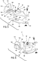
- Figs. 1-2 show an embodiment of a prosthetic system 5 comprising a pump system 3 and a prosthetic foot 4.
- the prosthetic foot 4 includes an ankle portion 6.
- the ankle portion 6 can include a first connection portion 8 such as a pyramid connector.
- the first connection portion 8 can attach to a stump on user, to another prosthetic system, or to any other appropriate object.
- the first connection 8 can include attachment features other than a pyramid connector, such as a threaded hole or screw, a latch, a magnetic member, tube clamp, or other features.
- the ankle portion 6 can additionally include second and third connection portions 10, 12.
- the ankle portion 6 can include or define a cover. The cover can protect various components of the prosthetic foot 4 such as electronics or other components.
- the ankle portion 6 can connect to an upper foot element 14 at the third connection point 12.
- the upper foot element 14 can be substantially plate-like and can have a generally rectangular cross-section along its length.
- the third connection point 12 can provide a rotatable connection, although non-rotatable connections can also be used.
- the rotation can be provided about an axle firmly mounted to the ankle portion 6, about which the upper foot element 14 can rotate.
- the upper foot element 14 can be fixed to the axle, and relative rotation can be allowed between the axle and ankle portion 6.
- An attachment portion 15 can be disposed at the proximal end of the upper foot element 14.
- the attachment portion 15 can include or define a bushing or opening through which the axle extends.
- the attachment portion 15 can be integral to the proximal end of the upper foot element 14 or a separate structure.
- the upper foot element 14 can be formed from a sufficiently flexible material such as carbon fiber.
- the upper foot element 14 can be substantially inelastic, so as to provide a rigid connection. It will be understood that the lower foot element and intermediate foot element (described below) can be formed of similar materials and have similar connections as the upper foot element 14.
- the upper foot element 14 can be formed into a shape arranged to provide a desired flexibility or rigidity. As seen, the upper foot element 14 can include a concave-forward portion 18 at or near the attachment portion 15, although other shapes are also possible such as an L-shape or J-shape. The upper foot element 14 can extend from the lower portion of the concave-forward portion 18 into a foot portion 20.
- the foot portion 20 can further include a slit that extends longitudinally to separate the foot portion 20 into two or more foot members that can flex independently. In other embodiments, the foot portion 20 can be monolithic without any slits.
- the ankle portion 6 can connect to a connection unit 22 at the second connection portion 10.
- the second connection portion 10 can be rotatable or non-rotatable.
- the third connection portion 12 is in front of the ankle portion 6, and the second connection portion 10 is in a rear portion of the ankle portion 6.
- the connection unit 22 is located at a rear portion of the prosthetic foot 4.
- the connection unit 22 can be positioned in a front portion of the prosthetic foot.
- connection unit 22 can be in a variety of forms such as a connection member, an actuator, a rod connector, a rigid member, or a piston cylinder.
- connection unit 22 is depicted as connecting to an intermediate foot element 24 at a fourth connection portion 26.
- the fourth connection portion 26 can be rotatable or non-rotatable.
- the intermediate foot element 24 can include or define a bushing or opening through which an axle extends to provide a rotatable connection or pivot axis between the intermediate foot element 24 and the connection unit 22.
- the intermediate foot element 24 can be substantially plate-like and can have a generally rectangular cross-section along its length.
- the intermediate foot element 24 can extend into a foot portion in a manner similar to the foot portion 20 of the upper foot element 14.
- the intermediate foot element 24 can include a slit similar to the slit of the upper foot element 14.
- the intermediate foot element 24 is disposed below the upper foot element 14, and extends tangentially forward and toward the upper foot element 14 to abut the upper foot element 14 along the foot portion 20 of the upper foot element 14.
- the upper and intermediate foot elements 14, 24 are depicted as ending at approximately the same point, in some embodiments the upper foot element 14 may extend further, or the intermediate foot element 24 may extend further.
- the prosthetic foot 4 can further include a lower foot element 28.
- the lower foot element 28 can extend from a heel portion 30 (e.g., a cantilevered or free end) at a bottom and rear portion of the prosthetic foot 4. This heel portion 30, as shown, can be spaced from the connection unit 22 and the intermediate foot element 24, curving downward toward and away from the connection unit 22. From the heel portion 30, the lower foot element 28 can extend to a toe portion 16 of the prosthetic foot 4, and can generally abut the foot portion of the intermediate foot element 24, as that member abuts the upper foot element 14. In the illustrated embodiment, the lower foot element 28 extends forward beyond the upper foot element 14 and the intermediate foot element 24.
- the lower foot element 28 can have a slit that generally matches the slits in the upper and intermediate foot elements.
- the prosthetic foot 4 can include one or more fastening members that couple two or more of the elements 14, 24, 28 to each other. Alternatively, two or more of the elements 14, 24, 28 can be coupled together with an adhesive or other suitable mechanism.
- Attachment can be provided between the elements 14, 24, 28, for example, generally in a metatarsal region of the prosthetic foot 4. Where the elements 14, 24, 28 are not held together (e.g., by the fastener members) they can separate and act as distinct flexible members instead of combining into a single flexible member where held together.
- the position of the one or more fastening members can be adjustable along the length of a slit defined in one or more of the elements 14, 24, 28.
- the fastener member is moved forward, the elements 14, 24, 28 are held together over a shorter range, allowing more separation between them, and thus greater flexibility (e.g., the lever arm of the intermediate foot element 24 is relatively longer, resulting in greater flexibility of the prosthetic foot 4.)
- the fastener member is moved rearward, the elements 14, 24, 28 are held together over a longer range, reducing the allowed separation and flexibility (e.g., the lever arm of the intermediate foot element 24 is relatively shorter, resulting in increased stiffness of the prosthetic foot 4).
- the one or more fastener members may be adjustable to vary the stiffness of the prosthetic foot 4.
- the flexibility and resistance of the elements 14, 24, 28 can be altered by the connection unit 22 (independently of, or in combination with, the one or more fastening members).
- the flexibility and resistance of the elements 14, 24, 28 can be altered manually and/or by an actuator.
- the prosthetic foot 4 can expand and compress.
- the prosthetic foot 4 is in expansion when the ankle portion 6 rotates in a counter-clockwise direction (e.g., the first connection portion 8 on the ankle portion 6 rotates away from the toe portion 16 of the prosthetic foot 4) and the connection unit 22 pushes the rear portion of the intermediate foot element 24 away from the upper foot element 14, increasing a distance 34 defined between the intermediate foot element 24 and the upper foot element 14.
- the prosthetic foot 4 can be in expansion independent of rotation of the ankle portion 6.
- the connection unit 22 can be an actuator that pushes the rear portion of the intermediate foot element 24 away from the upper foot element 14 to move the foot into expansion.
- the prosthetic foot 4 is in compression when the ankle portion 6 rotates in a clockwise direction (e.g., the first connection portion 8 on the ankle portion 6 rotates toward the toe portion 16 of the prosthetic foot 4) and the connection unit 22 pulls the rear portion of the intermediate foot element 24 toward from the upper foot element 14, closing the distance 34. It will also be appreciated that the prosthetic foot 4 can be in compression independent of rotation of the ankle portion 6.
- the connection unit 22 can be an actuator that pulls the rear portion of the intermediate foot element 24 toward the upper foot element 14 to move the foot into compression.
- the prosthetic foot 4 may be insertable into a foot cover 21 as seen in Fig. 2 .
- the gait cycle defines the movement of the leg between successive heel contacts of the same foot.
- the gait cycle has two phases: stance and swing. Of particular interest is the stance phase which generally includes heel-strike or initial contact, mid-stance, and toe-off.
- the mechanics of the prosthetic foot 4 come into play.
- the prosthetic foot 4 Upon heel strike, the prosthetic foot 4 is in expansion, providing cushioning to the user.
- the prosthetic foot 4 moves from expansion into compression.
- the prosthetic foot 4 remains in compression through toe-off until the weight of the user is removed from the prosthetic foot, at which time the prosthetic foot 4 returns to its resting position.
- the pump system 3 includes a pump mechanism 2 and a securing member 36.
- the pump mechanism 2 can be coupled to the prosthetic foot 4 at any suitable location, but is shown coupled to the concave-forward portion 18 located at or toward the proximal end of the upper foot element 14.
- the pump mechanism 2 can be made generally from carbon fiber and an elastomeric compound (e.g., a membrane) providing durable yet lightweight components.
- Prior art pump mechanisms are typically of heavy metal construction, which imposes a significant weight burden on the user when ambulating.
- the pump mechanism 2 is operably connected to the intermediate foot element 24 and the securing member 36 secured to the attachment portion of the upper foot element 14. As described in more detail below, relative movement between the securing member 36 and the intermediate foot element 24 moves the pump mechanism 2 between an original configuration and an expanded configuration.
- the pump mechanism 2 includes a housing 40 containing two valve assemblies 42 (shown in Fig. 1 ), 44, a membrane 46, and a connector 48.
- the valve assemblies can include a one-way valve, also referred to as a check valve.
- a preferred type of one-way valve used is a duckbill valve. It should be appreciated however that other types of one-way valves are possible.
- the valve assembly 42 is arranged to only allow fluid to enter the pump mechanism 2.
- the valve assembly 42 can be in fluid communication with the cavity of a prosthetic socket. When the volume of the pump mechanism 2 increases, fluid (e.g., air) can be drawn out from the socket via the valve assembly 42.
- the valve assembly 44 is arranged to only allow fluid to be expelled out of the pump mechanism 2, preferably to atmosphere.
- the housing 40 can be coupled to the securing member 36 via at least one fastener 50 situated at a front portion of the housing 40 and securing member 36.
- the pump mechanism 2 and/or pump system can be a separate add-on module to the prosthetic foot 4.
- the pump mechanism 2 can be removably attached to the securing member 36 via the fastener 50 and the connector 48. Because the pump mechanism 2 is not integrated into the prosthetic foot 4, failure of the pump mechanism 2 advantageously would not affect the performance of the prosthetic foot 4.
- the housing 40 can have a rigid configuration.
- the housing 40 can define a main portion 52, a front portion 54, and a rear portion 64 opposite the front portion 54.
- the main portion 52 can have any shape but is shown having a generally cylindrical shape.
- the front portion 54 can have an elongate configuration and extend forwardly over an upper surface of the securing member 36.
- the housing 40 can have a width that tapers from the main portion 52 to the front portion 54 such that the front portion 54 is narrower than the main portion 52. This advantageously can facilitate the pivoting and/or flexing of the housing 40 in the area of the front portion 54.
- the bottom surface of the front portion 54 can include a rocker-like curvature 55 that allows the housing 40 to rock back and forth as the pump mechanism 2 moves between original and expanded configurations described below.
- the front portion 54 can define a hole arranged to receive a shaft of the fastener 50.
- the rear portion 64 of the housing 40 defines an arm member 38 arranged to move or drive the pump mechanism 2 toward at least an expanded configuration (described below) upon movement of the intermediate foot element 24 relative to the upper foot element 14.
- the arm member 38 extends generally downward from the main portion 52 and has a lower end including an engagement surface 56 arranged to selectively engage with the upper surface of the intermediate foot element 24.
- the arm member 38 has a rigid configuration.
- the arm member 38 is shown as a push member but can comprise any suitable member.
- the bottom surface of the main portion 52 of the housing 40 defines a cavity 58 that is provided with an undercut circumferential groove 60 between an open end of the cavity 58 and a closed bottom 62 of the cavity 58.
- An outer radial edge portion of the membrane 46 can be situated in the circumferential groove 60 such that a seal is formed between the membrane 46 and the housing 40.
- an adhesive can be applied between the housing 40 and the outer radial edge portion of the membrane 46, increasing the sealing effect.
- the bottom 58 of the cavity 50 can define two openings which extend into the housing 40 to form internal passageways providing fluid communication between a fluid chamber defined below and the one-way valve assemblies 42, 44.
- the pump mechanism 2 is movable between an original configuration in which the volume of a fluid chamber 64 defined between the top surface of the membrane 46 and the bottom 62 of the cavity is zero or near-zero (shown in Fig. 2A ), and an expanded configuration in which the volume of the fluid chamber 64 is increased (shown in Fig. 2B ).
- the bottom 62 of the cavity 58 can substantially complement the top surface of the membrane 46 such that when no force is exerted on the pump mechanism 2 it is in the original configuration. Both the bottom 62 of the cavity 58 and the top surface of the membrane 46 can be generally flat.
- the pump mechanism 2 moves toward the expanded configuration (shown in Fig. 2B ) as the force pulls a portion of the membrane 46 away from the bottom 62 of the cavity 58, causing deformation of the membrane 46 and an increase in volume of the fluid chamber 64.
- This increase in volume of the fluid chamber 64 can draw fluid into the fluid chamber 64 from the socket through the one-way valve assembly 42.
- the housing 40 may be formed of metal such as stainless steel, carbon fiber, or plastic or any other material which would provide sufficient strength to resist deformation when pulled away from the membrane 46.
- the pump mechanism 2 returns toward its original configuration as the membrane 46 returns toward the bottom 62 of the cavity 58 and fluid within the fluid chamber 64 is expelled out of the one-way valve assembly 44.
- the membrane 46 can be elastomeric and can use at least in part its material properties to naturally or elastically return to its original position on the bottom 62 of the cavity 58.
- the membrane 46 may have any desired shape, but is shown having a generally circular or elliptical shape.
- the membrane 46 can be operatively attached at or near its center point to the securing member 36 while the outer radial edge portion of the membrane 46 is attached to the housing 40 such that when the membrane 46 is pulled away from the housing 40 a pocket forms in a middle area of the membrane 46 due to the deformation of the membrane 46.
- the formation of the pocket increases the volume of the fluid chamber 64.
- the pump mechanism 2 thus uses a compliant membrane to create suction.
- the connector 48 can have an upper radial flange 66 embedded in the membrane 46, a lower radial flange 68 below the membrane 46, and a shaft portion 70 extending between the upper flange 66 and the lower flange 68.
- the connector 48 may be of a two-piece construction such that the lower flange 68 can be threadedly removed from the upper flange 66 in the membrane 46.
- the connector 48 may be formed of metal, plastic, or any other suitable material.
- the upper flange 66 may extend substantially into the membrane 46 or may be formed of a material that is part of the membrane 46 (e.g., a flexible metal member).
- the securing member 36 can be a plate defining a rear portion 72, a front portion 74, and a middle portion 76 extending between the rear portion 72 and the front portion 74.
- the rear portion 72 defines a part extending generally upward that is attached to the attachment portion 15 of the upper foot element 14.
- the securing member 36 can be connected to the upper foot element 14 in any suitable manner but is shown attached via a fastener 78.
- the rear portion 72 can define an aperture for receiving the fastener 78 to connect the securing member 36 to the upper foot element 14.
- the middle portion 76 and front portion 74 extend forwardly from the rear portion 72 above the foot portion 20 of the upper foot element 14.
- the securing member 36 can have a flexible, rigid, and/or semi-rigid configuration.
- the securing member 36 can be operatively connected to the membrane 46 via the connector 48.
- the middle portion 76 of the securing member 36 can define a connector opening 80.
- the connector opening 80 can have a diameter that is oversized relative to the lower flange 68 of the connector 48.
- the shaft portion 70 and lower flange 68 of the connector 48 can be inserted through the connector opening 80.
- the connector 46 with the pump mechanism 2 can then be slid toward the rear portion 72 until the upper surface of the lower flange 68 engages a lower surface of the securing member 36 along the rearward side of the opening 80, properly positioning the pump mechanism 2 on the securing member and a portion of the lower flange 68 below the securing member 36.
- the housing 40 can be coupled to the securing member via the fastener 50, securing the membrane 46 to the securing member 36 via the connector 46.
- the securing member 36 defines a first through hole 81 and the upper foot element 14 defines a second through hole 83 through which the arm member 38 extends from the main portion 52 of the housing 40 toward the upper surface of the intermediate foot element 24. As such, portions of the arm member 38 are entirely surrounded by the upper foot element 14 or the securing member 36. This advantageously helps the prosthetic system maintain a low-profile configuration by routing the arm member 38 through the prosthetic foot 4 rather than around the prosthetic foot 4. It also beneficially helps protect the arm member 38 from inadvertent contact with external objects.
- the securing member 36 can be formed of carbon fiber or another suitable material.
- the location, shape, and/or length of the opening 80 and/or first and second through holes 81, 83 can be adjusted based on the size of the prosthetic foot 4 and/or pump mechanism 2, the weight of the user, and/or other factors.
- Figs. 1 and 2A show the prosthetic foot in its resting position.
- the engagement surface 56 on the arm member 58 can be lightly resting on or a small distance above the upper surface of the intermediate foot element 24, and the pump mechanism 2 is in its original configuration.
- the prosthetic foot 4 moves into expansion, which, in turn, causes the connection unit 22 to push the intermediate foot element 24 away from the engagement surface 56 of the arm member 38. With the prosthetic foot 4 in expansion, the pump mechanism remains in its original configuration.
- connection unit 22 pulls the intermediate foot element 24 toward the upper foot element 14, closing the distance 34 and applying an upward force on the engagement surface 56 of the arm member 38 as shown in Fig. 2B .
- the arm member 38 transfers the upward force on the engagement surface 56 to the housing 40, forcing the back portion 64 of the housing 40 away from the securing member 36.
- This causes the housing 40 to pivot and/or flex around the front portion of the housing 40 attached to the securing member 36, which, in turn, pulls the membrane 46 away from the housing 40, driving the pump mechanism 2 toward the expanded configuration.
- the arm member 38 drives the housing 40 away from the membrane 46 to deform the membrane 46 between the securing member 36 and the housing 40, increasing the volume of the fluid chamber 64.
- This increase in volume of the fluid chamber 64 creates a vacuum in the pump mechanism 2, pulling fluid into the pump mechanism 2 through the one-way valve assembly 42. Compression of the prosthetic foot 4 thus automatically creates a vacuum in the pump mechanism 2.
- the pump mechanism 2 does not need to be first compressed before it can create a vacuum upon decompression, the pump mechanism 2 can achieve smaller fluctuations in air pressure than the prior art devices, so the difference between the greatest pressure and lowest pressure in the vacuum space of the socket is less than compared to the prior art devices.
- the prosthetic foot 4 At the end of the stance phase or when the weight of the user is removed from the prosthetic foot 4, the prosthetic foot 4 returns to its resting position and the inherent properties of the housing 40 and/or membrane 46 can help move the pump mechanism 2 back toward its original configuration and decrease the volume of the fluid chamber 64 to a zero or near zero volume.
- the pump mechanism 2 expels fluid in the fluid chamber 64 out of the one-way valve assembly 44. Because the pump mechanism 2 returns to its original configuration of zero or near-zero volume in the fluid chamber 64 at the beginning or end of each gait cycle, all fluid drawn into the pump mechanism 2 is automatically expelled. This is advantageous because prior art devices rely on complete compression of the pump in expelling air in each gait cycle to use the pump to its maximum capacity. It is difficult for complete compression to occur in every cycle using the gait of a user as the actuating force since the impact and displacement of the pump is not consistent and varies between users.
- the securing member 36 and/or arm member 38 can be made of a durable but flexible material such as carbon fiber cloth, unidirectional composites, plastic, or metal.
- Fig. 3 includes a prosthetic system 5 comprising a vacuum suspension system 400 including the pump system 3 and the prosthetic foot 4.
- the vacuum suspension system 400 has a socket 401, a liner preferably including a seal component, a valve assembly 403, a tube 405 connecting the pump mechanism 2 to the socket 401, and the prosthetic foot 4.
- the socket 401 defines an interior space, and an interior wall delimiting the interior space.
- the vacuum suspension system 400 may also employ an adaptor system 407.
- the adaptor system 407 can be replaced with a shock and/or rotation module.
- the vacuum suspension system 400 provides improved proprioception and volume control since there is better attachment between the socket 401 and the residual limb.
- the vacuum suspension system 400 includes the pump system 3 having the pump mechanism 2 and the securing member 36, as described above, which provide a vacuum assisted suspension by generating a negative pressure (vacuum) inside the socket 401.
- the function of the vacuum suspension system 400 can be fully automatic.
- compression of the prosthetic foot 4 expands the pump mechanism 2 to efficiently draw fluid out of the socket 401 in each step.
- decompression of the prosthetic foot 4 permits the pump mechanism 2 to return to its original position, expelling the fluid drawn from the socket 401 to atmosphere.
- the pump mechanism 2 thus can create a negative pressure inside the socket 401, resulting in a secure and reliable elevated vacuum suspension that provides an intimate suspension as the negative pressure formed inside of the socket 401 holds the liner and the residual limb firmly to the socket wall.
- FIG. 4 Another embodiment of a prosthetic system 85 is shown in Figs. 4-6 .
- the prosthetic system includes the prosthetic foot 4 and a pump system 81.
- the pump system 81 includes a pump mechanism 82 and a securing member 88.
- the pump mechanism 82 is attached to the securing member 88 and situated above the upper foot element 14 of the prosthetic foot 4.
- the pump mechanism 82 is operably connected to the intermediate foot element 24 via an arm member and the securing member 88 is secured to the attachment portion on the upper foot element 14.
- the pump mechanism 82 includes a housing 90 containing two one-way valve assemblies 92, 94, a membrane 96 (shown in Fig. 4 ), and a connector 98 (shown in Fig. 4 ).
- the valve assembly 92 only allows fluid to enter the pump mechanism 82 which can be in fluid communication with the cavity of a socket.
- the valve assembly 94 only allows fluid to be expelled out of the pump mechanism 82, preferably to atmosphere.
- the connector 98 can include an upper radial flange embedded in the membrane 96, a lower radial flange below the membrane 96, and a shaft portion extending between the upper and lower flanges.
- the housing 90 can be coupled to the securing member 88 via at least one fastener 102 situated at a front portion of the housing 90 and the securing member 88.
- the housing 90 can have a rigid configuration.
- the housing 90 defines a main portion 104, a front portion 106, and a rear portion 108 opposite the front portion 106.
- the front portion 106 can have an elongate configuration and extend forwardly over an upper surface of the securing member 88.
- the rear portion 108 of the housing 90 can define an arm member 110 extending generally downward from the housing 90 and arranged to move or drive the pump mechanism 82 toward at least an expanded configuration (described below) upon movement of the intermediate foot element 24 relative to the upper foot element 14.
- the arm member 110 can comprise a push member having a lower end defining an engagement surface 112 arranged to engage with the upper surface of the intermediate foot element 24.
- the arm member 110 can have a rigid configuration.
- the pump mechanism 82 relies upon deformation of the membrane 96 to move between an original configuration in which the volume of a fluid chamber defined between the top surface of the membrane 96 and the bottom of the housing 90 is zero or near-zero, and an expanded configuration in which the volume of the fluid chamber is increased.
- the housing 90 is arranged to surround the outer radial edge portion of the membrane 96 and creates a seal with the membrane 96.
- the bottom surface of the housing 90 can define a pair of openings which extend into the housing 90 to form internal passageways to provide fluid communication between the fluid chamber and the two one-way valve assemblies 92, 94.
- the securing member 88 can comprise a plate member 114 and a backing portion 116.
- the backing portion 116 and the plate member 114 can be made of different materials.
- the plate member 114 can be made of carbon fiber cloth and the backing portion 116 can be made of metal, plastic, or another suitable material, facilitating production.
- the securing member 88 includes a two part construction, the length, curvature, and/or shape of the plate member 114 can be advantageously adjustable or customizable without having to replace the entire securing member 88.
- the plate member 114 can include a rear portion 117, a front portion 118, and a middle portion 120 extending between the rear and front portions 117, 118.
- the plate member 114 can be formed of carbon fiber cloth or another suitable material.
- the plate member 114 can have a width that tapers from the middle portion 120 toward the front portion 116 such that the front portion 118 is narrower than the middle portion 120.
- the front portion 118 can define an aperture 122 for receiving the fastener 102 to connect the plate member 114 to the front portion of the housing 90.
- the middle portion 120 defines an aperture 124 for connecting the plate member 114 to the connector 98.
- a slot or notch 126 is formed in the terminal edge of the rear portion 116 that allows the arm member 110 to extend through the plate member 114.
- the rear portion 116 can define a pair of apertures 128 on opposing sides of the notch 126.
- the backing portion 116 includes a base 130 and a back member 132.
- the upper surface of the base 130 defines a seat 134 arranged to accommodate the rear portion 116 of the plate member 114 when the plate member 114 is attached to the backing portion 116. This beneficially limits or prevents the plate member 114 from sliding sideways off of the backing portion 116.
- a slot or notch 136 is defined in the base 130 that generally corresponds to the notch 126 in the plate member 114, allowing the arm member 110 to extend through the base 130.
- the base 130 further defines a pair of apertures 138 in the seat 134 corresponding to the apertures 128 on the plate member 114 for receiving one or more fasteners to attach the plate member 114 to the backing portion 116.
- the back member 132 can extend generally upward from a rear end of the base 130.
- the back member 132 can be generally perpendicular to the base 130 or oblique relative to the base 130.
- the back member 132 can define an aperture 140 for receiving a fastener to connect the backing portion 116 to the upper foot element 14 and/or the attachment portion 15 (shown in Fig. 4 ) of the foot 4.
- the rear surface of the back member 132 can generally complement the front surface of the attachment portion 15.
- the rear surface of the back member 132 can define one or more alignment features including a pair of pin members 142 arranged to be received within a pair of corresponding openings defined in the attachment portion. These advantageously help align the fastener aperture 140 on the back member 132 and a fastener aperture on the attachment portion 15, facilitating connection and/or removal of the securing member from the foot.
- the prosthetic system 143 includes a prosthetic foot 144 and a pump system 145.
- the prosthetic foot 144 can be similar to other embodiments of the prosthetic foot. For instance, it can include an ankle portion 148 and an upper foot element 150 coupled to the ankle portion 148 via an attachment portion 180 (shown in Fig. 8 ).
- the attachment portion 180 can include or define a bushing or opening 181 through which an axle extends.
- An intermediate foot element 152 is disposed generally below the upper foot element 150 and attached to the upper foot element 150 at a front portion thereof.
- the prosthetic foot 144 can have a lower foot element 154 disposed below the intermediate foot element 152.
- the lower foot element 154 extends rearwardly to a free end and extends forwardly to a toe portion of the foot 144.
- a connection unit 156 can extend between the rear of the ankle portion 148 and the rear portion of the intermediate foot element 152. In use, the prosthetic foot 144 can expand and compress.
- the pump system 145 includes a pump mechanism 146 and a securing member 158.
- the pump mechanism 146 is situated above the upper foot element 150 and operably connected to the intermediate foot element 152 and the securing member 158 secured to the attachment portion 180 on the upper foot element 150.
- the pump mechanism 146 can be configured similarly to the previously described pump mechanisms.
- the pump mechanism 146 can include a housing 160 containing two one-way valve assemblies, a membrane, and a connector.
- One of the valve assemblies only allows fluid to enter the pump mechanism 146 which can be in fluid communication with the cavity of a socket.
- the other valve assembly only allows fluid to be expelled out of the pump mechanism 146, preferably to atmosphere.
- the connector can be attached to the membrane and the securing member 158 and can exhibit any suitable configuration.
- the connector may be a single fastener or screw, allowing the pump mechanism 146 to easily retrofit on a prosthetic foot.
- the pump mechanism 146 relies upon deformation of the membrane to move between an original configuration in which the volume of a fluid chamber defined between an upper surface of the membrane and the bottom of the housing 160 is zero or near-zero, and an expanded configuration in which the volume of the fluid chamber is increased.
- the housing 160 is arranged to surround the outer radial edge portion of the membrane and creates a seal with the membrane.
- the bottom of the housing 160 can define a pair of openings which extend into the housing 160 to form internal passageways to provide fluid communication between the fluid chamber and the two one-way valve assemblies.
- the securing member 158 can exhibit a two-part construction.
- the securing member 158 can include a plate member 160 and a backing portion 162.
- the backing portion 162 and the plate member 160 can be made of different materials.
- the plate member 160 can include a rear portion 164, a front portion 166, and a middle portion 168 extending between the rear and front portions.
- the plate member 160 can be formed of carbon fiber cloth or another suitable material.
- the plate member 160 can have any suitable shape but is shown having a width that tapers from the middle portion 168 toward the front portion 166 such that the front portion 166 is narrower than the middle portion 168.
- the middle portion 168 can define an aperture 170 for connecting the securing member 158 to the connector.
- a cutout 172 is defined in the plate member 160 at or near the rear portion 164 that allows an arm member of the pump mechanism 146 to extend through the plate member 160 toward the intermediate foot element 152.
- the rear portion 164 can define a connection tab 174 that extends generally upward from the plate member 160.
- the connection tab 174 can define an aperture for receiving a fastener 178 to connect the securing member 158 to the prosthetic foot 144.
- the backing portion 162 extends generally upright or obliquely relative to the plate member 160.
- the backing portion 162 can define an internal cavity with an open bottom into which the connection tab 174 can be inserted.
- the backing portion 162 can also define an aperture 176 for receiving the fastener 178.
- the connection tab 174 of the plate member 160 can be inserted into the backing portion 162.
- the connection tab 174 and the backing portion 162 can then be secured to the attachment portion 180 of the prosthetic foot 144 by inserting the fastener 178 through the apertures. This advantageously allows the securing member 158 to be directly attached to the prosthetic foot 144 using a single fastener as opposed to multiple fasteners, facilitating the retrofit of a prosthetic foot with the pump system.
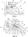
- the prosthetic system comprises a pump system 182 and the prosthetic foot 4.
- the pump system 182 includes a pump mechanism 184 and a securing member 186.
- the pump mechanism 184 is attached to the securing member 186 and situated above the upper foot element 14.
- the pump mechanism 184 is operably connected to the intermediate foot element 24 via an arm member 208 and the securing member 186 is secured to the attachment portion 15 on the upper foot element 14.
- the prosthetic foot 4 may be insertable into a foot cover 218 as seen in Fig. 10 .
- the pump mechanism 184 includes a housing 188 containing two one-way valves 190, 192, a membrane 194, and a connector 196.
- the valve assembly 190 only allows fluid to enter the pump mechanism 184 and the valve assembly 192 only allows fluid to be expelled out of the pump mechanism 184.
- the connector 196 can include an upper radial flange embedded in the membrane 194, and a lower radial flange below the membrane 194, and a shaft portion extending between the upper and lower flanges.
- the housing 188 can have a rigid configuration and can define a main portion 198, a front portion 202, and a rear portion 204 opposite the front portion 202.
- the front portion 202 can have an elongate configuration and extend forwardly and downwardly from the main portion 198 to a front edge 206 arranged to engage the upper surface of the upper foot element 14.
- the rear portion 204 can define the arm member 208.
- the arm member 208 is arranged to drive or move the pump mechanism 184 toward at least an expanded configuration (described below) upon engagement with the intermediate foot element 24 and movement of the intermediate foot element 24 relative to the upper foot element 14.
- the arm member 208 can be any suitable mechanism but is shown comprising a push member extending generally downward to a lower end defining an engagement surface 210 arranged to engage with the upper surface of the intermediate foot element 24.
- the arm member 208 can have a rigid configuration.
- the pump mechanism 184 relies upon deformation of the membrane 194 to move between an original configuration in which the volume of a fluid chamber 195 defined between the top surface of the membrane 194 and the bottom of the housing 188 is zero or near-zero, and an expanded configuration in which the volume of the fluid chamber is increased.
- the housing 188 is arranged to surround the outer radial edge portion of the membrane 194 and creates a seal with the membrane 194.
- the bottom surface of the housing 188 can define a pair of openings which extend into the housing 188 to form internal passageways, providing fluid communication between the fluid chamber and the two one-way valve assemblies 190, 192.
- the securing member 186 can be a plate defining a first part 214 extending below a portion of the housing 188 and a second part 212 extending generally upward from the first part and attached to the attachment portion 15 of the upper foot element 14.
- the first part 214 of the securing member 186 can be connected to the housing 188 in any suitable manner.
- the first part of the securing member 186 can be bonded to the front portion of the housing 188.
- the first part 214 can secured to the housing 188 via the connector 196 extending through an opening 216 defined in the first part 214.
- the securing member 186 can be connected to the attachment portion 15 in any suitable manner but is shown attached via a fastener.
- the second part 212 can define an aperture for receiving the fastener to connect the securing member 186 to the attachment portion 15 or upper foot element 14.
- the front edge 206 of the housing 188 is engaged with the upper surface of the upper foot element 14 and the pump mechanism 184 is in its original configuration.
- the prosthetic foot 4 moves into expansion, which, in turn, causes the connection unit 22 to push the intermediate foot element 24 away from the engagement surface 210 of the arm member 208.
- the pump mechanism remains in its original configuration.
- connection unit 22 pulls the intermediate foot element 24 toward the upper foot element 14, applying an upward force on the engagement surface 210 of the arm member 208.
- This upward force drives the arm member 208 upward, forcing the rear portion 204 away from the securing member 186 and causing the housing 188 to pivot around the connection between the securing member 186 and the housing 188.
- the prosthetic foot 4 returns to its resting position and the inherent properties of the housing 188 and/or membrane 194 help move the pump mechanism 184 back toward its original configuration.
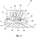
- FIG. 11-13 Another embodiment of a prosthetic system 223 comprising a pump system 220 and the prosthetic foot 4 is shown in Figs. 11-13 .
- This embodiment can be similar to the previously described embodiments except that the pump system has a different construction.
- the pump system 220 includes a pump mechanism 222 and an arm member 224 arranged to move or drive the pump mechanism 222 toward at least an expanded configuration (described below) upon movement of the intermediate foot element 24 relative to the upper foot element 14.
- the pump mechanism 222 includes a housing 226, at least one inlet valve assembly 228, at least one outlet valve assembly 230, a membrane 232 (shown in Fig. 12 ), and a connector 234 (shown in Fig. 12 ).
- the pump mechanism 222 relies upon of the membrane 232 to move between an original configuration in which the volume of a fluid chamber 233 defined between an upper surface of the membrane 232 and the bottom of the housing 226 is zero or near-zero, and an expanded configuration in which the volume of the fluid chamber 233 is increased.
- the housing 226 can have a rigid configuration and defines a main portion 236, and a rear portion 238 extending generally upwardly or obliquely from the main portion 236.
- the housing 226 can be coupled to the attachment portion 15 via at least one fastener.
- a rear surface of the rear portion 238 can generally complement the front surface of the attachment portion 15.
- the pump mechanism 222 can be a separate add-on module to the prosthetic foot 4. Because the pump mechanism 222 is not integrated into the prosthetic foot 4, failure of the pump mechanism 222 beneficially would not affect the performance of the prosthetic foot 4.
- the arm member 224 can be a plate located over the upper foot element 14.
- a front portion 225 of the plate 224 is connected to the pump mechanism 222 via the connector 234.
- the front portion 225 of the plate 224 can define an aperture 243 (shown in Fig.12 ) for connecting the plate 224 to the membrane 232 via the connector 234.
- the plate 224 has two arms 240 which extend along each side of the prosthetic foot 4 from the plate 224 to the rear area of the intermediate foot element 24.
- Each arm 240 can include a rear portion defining an engagement surface 242 arranged to engage with the rear portion of the intermediate foot element 24.
- the pump system 220 utilizes the displacement which occurs between the intermediate foot element 24 and the upper foot element 14 during the gait cycle to move the pump mechanism 222 between its original and expanded configurations.
- Fig. 12 shows the prosthetic foot 4 in its resting position.
- the prosthetic foot 4 moves into expansion, which, in turn, causes the connection unit 22 to push the intermediate member 24 away from the engagement surface 242 of the plate 224.
- the pump mechanism With the prosthetic foot 4 in expansion, the pump mechanism remains in its original configuration.
- connection unit 22 pulls the intermediate foot element 24 toward the upper foot element 14, closing the distance therebetween and applying an upward force on the engagement surface 242 of the plate 224.
- the plate 224 then transfers this upward force to the pump mechanism 222, driving the pump mechanism 222 toward the expanded configuration.
- the upward force on the engagement surface 242 causes the plate 224 to pivot or rotate at or near the rear portion 238 of the housing 226, rotating the front portion of the plate 224 attached to the membrane 232 away from the housing 226. This forces the pump mechanism 222 toward the expanded configuration.
- the pump mechanism 222 can be arranged at various points on the front of the prosthetic foot in combination with different angles of the arms 240 to control the length of the displacement between the original and expanded configurations.
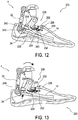
- FIG. 14 Another embodiment of a prosthetic system 247 comprising a pump system 246 and a prosthetic foot 248 is shown in Fig. 14 .
- the prosthetic foot 248 can be similar to other embodiments of the prosthetic foot.
- it can include an ankle portion 250 and an upper foot element 252 coupled to the ankle portion 250 via an attachment portion 254.
- the attachment portion 254 can include or define a bushing or opening through which an axle extends.
- An intermediate foot element 256 is disposed generally below the upper foot element 252 and attached to the upper foot element 252 at a front portion thereof.
- a lower foot element can be disposed below the intermediate foot element.
- a connection unit 258 can extend between the rear of the ankle portion 250 and the rear portion of the intermediate foot element 256. In use, the prosthetic foot 248 can expand and compress.
- the pump system 246 includes a pump mechanism 260 coupled to the ankle portion 250 and an arm member 262 coupled to the attachment portion 254 or upper foot element 252.
- the arm member 262 is arranged to move or drive the pump mechanism 260 toward at least an expanded configuration (described below) upon movement of the intermediate foot element 256 and/or the ankle portion 250 relative to the upper foot element 252.
- the pump mechanism 260 includes a housing 264 containing two one-way valve assemblies, a membrane 278, and a connector 280. One of the valve assemblies only allows fluid to enter the pump mechanism 246 and the other only allows fluid to be expelled out of the pump mechanism 260.
- the connector can be attached to the membrane and the arm member 262 and can exhibit any suitable configuration. For instance, the connector may be a fastener or screw.
- the housing 264 can include a main portion 270 having a generally cylindrical configuration and a rear portion 272 defining a pair of arms extending from the main portion 270.
- the rear portion 272 can be secured to the ankle portion 250.
- a bottom surface of the rear portion 272 can generally complete a portion of the front surface of the ankle portion 250.
- the pump mechanism 260 relies upon deformation of the membrane 278 to move between an original configuration in which the volume of a fluid chamber defined between an upper surface of the membrane 278 and the bottom of the housing 264 is zero or near-zero, and an expanded configuration in which the volume of the fluid chamber is increased.
- the housing 264 is arranged to surround the outer radial edge portion of the membrane 278 and creates a seal with the membrane 278.
- the bottom of the housing 264 can define a pair of openings which extend into the housing 264 to form internal passageways to provide fluid communication between the fluid chamber and the two one-way valve assemblies.
- the arm member 262 can comprise a resilient or flexible member having a configuration that wraps around a side of the attachment portion 254 to the front of the attachment portion 254. For instance, the arm member 262 defines a first end 274 secured to the side of the attachment portion 250 via a fastener and a second end 276 attached to the connector 280.
- the prosthetic foot 248 moves into expansion as the ankle portion 150 rotates in a first direction (e.g., counter-clockwise direction) and the intermediate foot element 256 moves away from the upper foot element 252.
- a first direction e.g., counter-clockwise direction
- the intermediate foot element 256 moves away from the upper foot element 252.
- this movement of the ankle portion 150 and/or the intermediate foot element 256 causes the arm member 262 on the attachment portion 254 to pull the membrane 278 away from the housing 270, moving the pump mechanism 260 to the expanded configuration.
- the ankle portion 250 rotates in a second direction (e.g., clockwise) and the prosthetic foot 248 moves into compression. This rotates the pump mechanism 260 toward the attachment portion 254 and moves the pump mechanism 260 back towards its original configuration.
- the prosthetic foot 248 returns to its resting position and the inherent properties of the arm member 262 help move and/or maintain the pump mechanism 260 in its original configuration.
- the pump system 246 can be a separate add-on module to the prosthetic foot 248. Because of the location and simple connection of the pump system 246 to the foot, it provides a low-profile design and reduces the likelihood that the pump system 246 will interfere with the performance of the foot.
- FIG. 15 Another embodiment of a prosthetic system 293 comprising a pump system 282 and the prosthetic foot 248 is shown in Fig. 15 .
- This embodiment may be similar to the sixth embodiment except that the pump system 282 includes a housing 286 and an arm member 288 having a different construction.
- the pump mechanism 282 can be coupled to the ankle portion 250 and the arm member 288 can be coupled to the attachment portion 254 or upper foot element 252.
- the housing 286 can include a main portion 290 having a generally cylindrical configuration and a rear portion 292 defining a pair of arms extending from the main portion 290.
- the rear portion 292 can be secured to the ankle portion 250.
- Each of the arms can have a portion exhibiting a width greater than the main portion 290, creating a gap between the bottom surface of the housing 286 and the attachment portion 254 of the foot 248.
- the arm member 288 can comprise a resilient member extending between the front surface of the attachment portion 254 and a connector 294 of the pump mechanism 282.
- the arm member 288 can include a rear end portion including a mounting member 296 attached to the front surface of the attachment portion 254 and a front end portion 298 defining an opening for attaching the arm member 288 to a membrane 302 of the pump mechanism 282.
- the prosthetic foot 248 moves into expansion as the ankle portion 150 rotates in a first direction (e.g., counter-clockwise direction) and the intermediate foot element 256 moves away from the upper foot element 252.
- a first direction e.g., counter-clockwise direction
- the intermediate foot element 256 moves away from the upper foot element 252.
- the ankle portion 250 rotates in a second direction (e.g., clockwise) and the prosthetic foot 248 moves into compression. This rotates the pump mechanism 282 toward the attachment portion 154 and moves the pump mechanism 282 back towards its original configuration.
- FIG. 16-18 Another embodiment of a prosthetic system 301 is shown in Figs. 16-18 .
- the prosthetic system 301 includes a prosthetic foot 302 and a pump system 304.
- the pump system 304 includes a pump mechanism 306 and a securing member 308.
- the pump mechanism 306 is attached to the securing member 308 and situated above an upper foot element 310 of the prosthetic foot 302.
- the pump mechanism 306 is operably connected to an intermediate foot element 312 of the prosthetic foot 302.
- the pump mechanism 306 includes a housing 314 containing two one-way valve assemblies 316, 318, a membrane 320 (shown in Fig. 16 ), and a connector 322.
- the valve assembly 316 only allows fluid to enter the pump mechanism 306 which can be in fluid communication with the cavity of a socket.
- the valve assembly 318 only allows fluid to be expelled out of the pump mechanism 306, preferably to atmosphere.
- the connector 322 can be any suitable connector. For instance, it can include an upper radial flange embedded in the membrane 320, a lower radial flange below the membrane 320, and a shaft portion extending between the upper and lower flanges.
- the housing 314 can be coupled to the securing member 308 via at least one fastener 324 situated at the front portion of the housing 314 and the securing member 308.
- the housing 314 can have a rigid configuration.
- the housing 314 defines a main portion 326, a front portion 328, and a rear portion 330 opposite the front portion 328.
- the front portion 328 can have an elongate configuration and extend forwardly over or along an upper surface of the securing member 308.
- the rear portion 330 of the housing 314 can be associated with an arm member 332 arranged to move or drive the pump mechanism 306 toward at least an expanded configuration upon movement of intermediate foot element 312 and/or the ankle portion 250.
- the arm member 332 can comprise an elongate member 332 extending generally downward from the housing 314 and can be integral to or separate from the housing 314.
- the arm member 332 can be selectively secured to the rear portion 330 of the housing 314 via at least one fastener 334 respectively positioned in at least one fastener hole defined by the arm member 332 and at least one fastener hole defined in the bottom surface of the rear portion 330. Because the arm member 332 can be easily removed from the housing 314 and replaced, the length, stiffness, and/or shape of the arm member 332 can be advantageously adjustable or customizable without having to replace the entire housing 314.
- the bottom surface of the rear portion 330 can define a keyway 336 and a corresponding key 338 can be defined on an upper surface of the arm member 332.
- the key 338 slides into the keyway 336 defined by the housing 314. This prevents relative rotation between the arm member 332 and the housing 314. It also provides a solid connection between the arm member 332 and the housing 314 by increasing the contact surface area between the arm member 332 and the housing 314. It further aligns the fastener holes, facilitating assembly and/or disassembly of the pump mechanism 306.
- the arm member 332 has an upper head portion for connection to the housing 314 and a shaft portion extending downwardly from the head portion.
- the shaft portion has a lower end defining an engagement surface 341 arranged to engage with an upper surface of the intermediate foot element 312.
- the shaft portion of the arm member 332 can include a width or a cross-sectional area that increases toward the engagement surface 341, providing a more solid connection between the arm member 332 and the intermediate foot element 312.
- the pump mechanism 306 relies upon deformation of the membrane 320 to move between an original configuration in which the volume of a fluid chamber defined between the top surface of the membrane 320 and the bottom of the housing 314 is zero or near-zero, and an expanded configuration in which the volume of the fluid chamber is increased.
- the housing 314 can be arranged to surround the outer radial edge portion of the membrane 320 and creates a seal with the membrane 320.
- the bottom surface of the housing 314 can define a pair of openings which extend into the housing 314 to form internal passageways, providing fluid communication between the fluid chamber and the two one-way valve assemblies 316, 318.
- the securing member 308 can include a plate member 340 and a backing portion 342.
- the backing portion 342 and the plate member 340 can be made of different materials.
- the plate member 340 can be made of carbon fiber cloth and the backing portion 342 can be made of metal, plastic, combinations thereof, or any other suitable material, facilitating production.
- the securing member 308 includes a two part construction, the length, curvature, and/or shape of the plate member 340 or backing portion 342 can be beneficially adjustable or customizable without having to replace the entire securing member 308.
- the plate member 340 can include a rear portion 344, a front portion 346, and a middle portion 348 extending between the rear and front portions 344, 346.
- the plate member 340 can have any suitable shape but is shown having a width that tapers from the middle portion 348 toward the front portion 346 such that the front portion 346 is narrower than the middle portion 348.
- the front portion 346 can define an aperture for receiving the fastener 324 to connect the plate member 340 to the front portion of the housing 314.
- the middle portion 348 can define an aperture for connecting the plate member 340 to the connector 322.
- a slot or notch 350 is formed in the terminal edge of the rear portion 344 that allows the arm member 332 to extend through the plate member 340 toward the intermediate foot element 312 of the foot 302.
- the rear portion 344 can define a pair of apertures on opposing sides of the notch 350.
- the backing portion 342 includes a base 352 and a back member 354.
- the bottom surface of the base 352 defines a seat 356 arranged to accommodate the rear portion 344 of the plate member 340 when the plate member 340 is attached to the backing portion 342. This beneficially limits or prevents the plate member 340 from sliding sideways off of the backing portion 342.
- a slot or notch 358 is defined in the base 352. The slot 358 can accommodate a portion of the housing 314 and allow the arm member 332 to extend through the base 352.
- the base 352 defines a pair of apertures in the seat 356 corresponding to the apertures on the plate member 340 for receiving one or more fasteners 360 to attach the plate member 340 to the backing portion 342.
- the seat 356 can be in part defined by a pair of side arms 362 defined on the backing portion 342 extending along a portion of the sides of the plate member 340. This helps align the fastener apertures formed in the base and plate member 340, facilitating assembly.
- the back member 354 can extend generally upward from a rear end of the base 352.
- the back member 354 can be generally perpendicular to the base 352 or oblique relative to the base 352.
- the back member 354 can define an aperture 362 for receiving a fastener to connect the backing portion 342 to the attachment portion 305 or upper foot element of the foot 302.
- the pump system 304 can include one or more features for adjusting the sensitivity of the pump mechanism.
- the aperture 362 can have an elongate configuration for receiving the fastener 364. This allows the fastener 364 to slide up and down within the aperture 362 such that the position of the pump system 304 relative to the upper foot element 310 and/or intermediate foot element 312 can be adjusted before a user tightens the fastener 364 to securely attach the securing member 308 to the attachment portion of the upper foot element 310.
- the height adjustability of the pump system 304 on the attachment portion 305 can in turn vary the sensitivity of the pump mechanism 306, which may depend on user activity level, weight, and/or other factors. For instance, by adjusting the height of the pump system 304 on the attachment portion 305, the amount and/or period of force applied to the arm member 332 may be adjusted, varying the sensitivity of the pump mechanism 306 to action of the prosthetic foot 302, advantageously making the pump mechanism 306 customizable to the needs of the user or desires of a clinician.
- the notch 350 and/or the apertures in the plate member 340 for receiving the connector 322 and the fastener 324 can have an elongate configuration such that the pump mechanism 306 can slide forward and/or backward along the plate member 340 relative to the attachment portion 305. Independent of or in combination with the height adjustability, this axial or longitudinal adjustability of the pump system 304 along the plate member 340 can vary the sensitivity of the pump mechanism 306.
- the pump mechanism 306 forwardly toward the front of the foot 302 along the plate member 340, the amount of relative movement between the intermediate foot element 312 and the upper foot element 310 required to actuate the pump mechanism 306 is reduced because of the tapering separation between the intermediate foot element 312 and the upper foot element 310, varying the sensitivity of the pump mechanism 306 to action of the foot 302.
- the lower end of the arm member 332 can include a wedge or tapered shape arranged to more easily advance between the intermediate foot element 312 and the upper foot element 310.
- the aperture in the housing 314 for receiving the fastener 324 can have an elongate configuration similar to the aperture in the plate member 340 such that the distance between the arm member 332 and the connection of the housing 314 to the plate member 340 is adjustable. This in turn permits the magnitude of the moment generated as the arm member 332 pushes on the housing 314 to be adjusted, varying the sensitivity of the pump mechanism 306.
- the rear surface of the back member 354 can generally complement the front surface of the attachment portion 305. As seen, the rear surface of the back member 354 can define one or more grooves 366 arranged to accommodate one or more projections associated with the attachment portion 305 as the height of the pump system 304 relative to the intermediate foot element is adjusted.
- the back member 354 can include one or more alignment features arranged to help align the securing member 308 on the attachment portion 305.
- the back member 354 can define a pair of opposing members 368 protruding rearwardly from the sides of the back member 354 and arranged to engage or extend along opposing sides of the attachment portion 305 when the securing member 308 is positioned on the attachment portion 305. This beneficially helps align the fastener aperture 362 on the back member 354 and a fastener aperture on the attachment portion 305, facilitating connection and/or removal of the securing member 308 from the foot 302. It also helps limit or prevent relative movement or rotation between the back member 354 and the attachment portion 305.
- FIG. 19 Another embodiment is shown in Figs. 19 and 20 .
- This embodiment can include a pump mechanism 370 arranged to be operably connected to a prosthetic foot such that action of the prosthetic foot can actuate the pump mechanism 370.
- the pump mechanism 370 can be a separate add-on module to the prosthetic foot.
- the pump mechanism 370 can be similar to the previous embodiments described.
- the pump mechanism 370 includes a housing 372 containing one or more valve assemblies, a membrane 374, and a connector 376.
- the one or more valve assemblies can include a one-way valve, also referred to as a check valve.
- a preferred type of one-way valve used is a duckbill valve. It should be appreciated however that other types of one-way valves are possible.
- the one or more valve assemblies can include a valve assembly arranged to only allow fluid to enter the pump mechanism 370.
- the valve assembly can be in fluid communication with the cavity of a prosthetic socket. When the volume of the pump mechanism 370 increases, fluid (e.g., air) can be drawn out from the socket via the valve assembly.
- fluid e.g., air
- the one or more valve assemblies can include another valve assembly arranged to only allow fluid to be expelled out of the pump mechanism 370, preferably to atmosphere.
- the housing 372 can have a rigid configuration.
- the housing 372 can have any shape but is shown having a generally cylindrical shape.
- the bottom surface of the housing 372 defines a cavity 378 that is provided with an undercut circumferential groove 380 between an open end of the cavity 378 and a closed bottom 382 of the cavity 378.
- An outer radial edge portion of the membrane 374 can be situated in the circumferential groove 380 such that a seal is formed between the membrane 374 and the housing 372.
- an adhesive can be applied between the housing 372 and the outer radial edge portion of the membrane 374, increasing the sealing effect.
- the bottom 382 can define two openings which extend into the housing 372 to form internal passageways providing fluid communication between a fluid chamber defined below and the one or more valve assemblies.
- the pump mechanism 370 is movable between an original configuration in which the volume of a fluid chamber 384 defined between the top surface of the membrane 374 and the bottom 382 of the cavity 378 is zero or near-zero, and an expanded configuration in which the volume of the fluid chamber 384 is increased.
- the bottom 382 of the cavity 378 can substantially complement the top surface of the membrane 374. Both the bottom 382 of the cavity 378 and the top surface of the membrane 374 can be generally flat.
- the membrane 374 may have any desired shape, but is shown having a generally circular or elliptical shape.
- the membrane 374 can be operatively attached at or near its center to the connector 376 while the outer radial edge portion of the membrane 374 is attached to the housing 372 such that when the connector 376 pulls the membrane away from the housing 372, for example, a pocket forms in a middle area of the membrane 374 due to the deformation of the membrane 374.
- the formation of the pocket increases the volume of the fluid chamber 384.
- the pump mechanism 370 thus uses a compliant membrane to create suction.
- the connector 376 can have an upper portion 386 embedded in the membrane 374, a lower portion 388 below the membrane 374, and a shaft portion 390 extending between the upper and lower portions 386, 388.
- the connector 376 may be of a two-piece construction such that the lower portion 388 can be threadedly removed from the upper portion 386 in the membrane 374.
- At least the upper portion 386 of the connector 376 can include one or more ferromagnetic materials such as steel, iron, cobalt, or other suitable metal.
- the upper portion 386 may extend substantially into the membrane 374.
- the pump mechanism 370 can include a closure-assist mechanism 392 arranged to bias or move the pump mechanism 370 toward its original configuration and/or maintain it therein.
- the closure-assist mechanism 392 comprises a closure element 392 secured within a cavity or an opening 394 defined in the bottom 382 of the cavity 378.
- the closure element 392 can include one or more magnetic materials such that magnetism can attract or pull the ferromagnetic upper portion 386 of the connector 376 toward the bottom 382 of the cavity 378, which, in turn, attracts or pulls the membrane 374 toward the bottom 382.
- the closure element 392 can include ferromagnetic materials and the connector 376 can be a magnet, or both may include magnetic materials.
- the closure element 392 can be omitted.
- the housing 372 may include one or more magnetic materials.
- the pump mechanism 370 can move toward the expanded configuration as the expansion force pulls a portion of the membrane 374 away from the bottom 382 of the cavity 378, causing deformation of the membrane 374 and an increase in volume of the fluid chamber 384.
- This increase in volume of the fluid chamber 384 can draw fluid into the fluid chamber 384 from a socket through the one or more valve assemblies.
- the housing 372 may be formed of metal such as stainless steel, carbon fiber, plastic or any other material which would provide sufficient strength to resist deformation when pulled away from the membrane 374.
- the pump mechanism 370 returns toward its original configuration as the membrane 374 returns toward the bottom 382 of the cavity 378 and fluid within the fluid chamber 384 is expelled out of the pump mechanism 370.
- the closure force between the upper portion 386 of the connector and the closure element 392 can move the membrane 374 to its original position on the bottom 382 on the cavity 378. This beneficially helps expel fluid from the fluid chamber 384 as its volume is decreased to zero or near-zero. It also advantageously helps maintain the pump mechanism 370 in its original configuration. It can also help maintain the membrane 374 sealed against the housing when no force or smaller forces are exerted on the membrane 374 by the connector and/or the prosthetic foot. Further, the closure force can be customized based on the individual needs of the user. For example, the magnetic strength of the closure element 392 can be selected to vary the closure force.
- FIG. 21-23 Another embodiment is shown in Figs. 21-23 .
- This embodiment can include a pump mechanism 396 arranged to be operably connected to a prosthetic foot such that action of the prosthetic foot moves the pump mechanism 396 between an original configuration and an expanded configuration to create an elevated vacuum.
- the pump mechanism 396 can be a separate add-on module to the prosthetic foot.
- the pump mechanism 396 can be similar to the previous embodiments described in many respects.
- the pump mechanism 396 includes a housing 398, a membrane 402, and a connector 404.
- the housing 398 can include at least one valve assembly 406 arranged to only allow fluid to enter the pump mechanism 396 and can be in fluid communication with the cavity of a prosthetic socket.
- the at least one valve assembly 406 can include a one-way valve or check valve.
- a preferred type of one-way valve used is a duckbill valve however other types of one-way valves are possible.
- the housing 398 can have a rigid configuration.
- the housing 398 can include an upper member 408 and a base member 410.
- the upper member 408 can have any shape but is shown having a generally cylindrical shape with a body portion.
- the bottom surface of the upper member 408 can define an opening 412 which extends into the upper member 408 to form an internal passageway providing fluid communication between a fluid chamber defined below and the at least one valve assembly 406.
- the membrane 402 is arranged to engage the bottom of the upper member 408 such that a seal can be created therebetween.
- the membrane 402 may have any desired shape, but is shown having a generally circular configuration.
- the bottom surface of the membrane 402 can have a contour tapering toward the center.
- the pump mechanism 396 is movable between an original configuration in which the volume of a fluid chamber 414 defined between the top surface of the membrane 402 and the bottom of the upper member 408 is zero or near-zero, and an expanded configuration in which the volume of the fluid chamber 414 is increased.
- the bottom of the upper member 408 can substantially complement the top surface of the membrane 402. Both the bottom of the upper member 408 and the top surface of the membrane 402 can be generally flat.
- the connector 404 can have an upper portion 416 embedded in the membrane 402 and a shaft portion 418 extending downwardly from the upper portion 416.
- the upper portion 416 may extend substantially into the membrane 402.
- the connector 404 can include a lower portion comprising a fastener arranged to be threadedly removable from the connector 404.
- the membrane 402 can be operatively attached at or near its center to the connector 404. As disclosed in more detail below, when the connector 404 pulls the membrane 402 away from the upper member 408 a pocket forms in the middle area of the membrane 402 due to the deformation of the membrane 402. The formation of the pocket increases the volume of the fluid chamber 414.
- the pump mechanism 396 thus uses a compliant membrane to create suction.
- the base member 410 may have any desired shape, but is shown having a circular shape defining an interior opening 420.
- the outer edge portion of the bottom of the membrane 402 rests on the portion of the base member 410 surrounding the opening 420 and a center portion of the membrane 402 and the shaft portion 418 are situated within or extend through the opening 420.
- the opening 420 can be dimensioned and configured such that the base member 410 does not undesirably interfere with movement of the membrane 402 and connector 404 during operation of the pump mechanism 396.
- a plurality of connecting portions 422 are circumferentially spaced around the outer periphery of the base member 410, defining spaces or gaps 430 between the connecting portions 422.
- Each connecting portion 422 includes a generally upright part 424 and a flange part 426 extending radially inward from the top of the upright part 424.
- the flange part 426 is arranged to extend over and engage an upper surface of the upper member 408 such that the membrane 402 can be retained or secured between the upper member 408 and the base member 410.
- the pump mechanism 396 moves toward the expanded configuration as the connector 404 pulls a center portion of the membrane 402 away from the bottom of the upper member 408 while the outer edge portion of the membrane 402 remains engaged with the upper member 408, causing deformation of the membrane 402 and an increase in the volume of the fluid chamber 414.
- This increase in volume of the fluid chamber 414 can draw fluid into the pump mechanism 396 through the valve assembly 406.
- the pump mechanism 396 can return toward its original configuration as the membrane 402 returns toward the bottom of the upper member 408.
- This closing movement decreases the volume of the fluid chamber 414, which, in turn, increases the pressure within the fluid chamber 414 until the seal between the upper surface of the membrane 402 and the upper member 408 is broken, allowing fluid in the fluid chamber 414 to be expelled out of the sides of the pump mechanism 396 through the gaps 430 between the connecting portions 422.
- the fluid in the fluid chamber 414 can escape from between the upper member 408 and the membrane 402 out the side of the housing 398.
- the membrane 402 can be elastomeric and can use at least in part its material properties to naturally or elastically return to its original position on the bottom of the upper member 408.
- the prosthetic device may include arm or plate operatively connected to the prosthetic foot and arranged to bias or force the membrane 402 toward the bottom of the upper member 408, helping to keep the membrane 402 sealed against the upper member 408.
- the pump mechanism 396 can include a closure-assist mechanism such as a spring or metal clip to bias or help return the membrane 402 toward the bottom of the upper member 408.
- the pump mechanism 396 can include a resilient member that engages the upper member 408 and the membrane 402 and/or the connector. The resilient member biases the membrane 402 toward the bottom of the upper member 408.
- the resilient member can comprise a generally u-shaped member, a torsion spring, a torsion bar, or any other suitable member.
- the pump mechanism 396 can expel fluid, preferably to atmosphere, without the use of a second valve assembly or a second port in the housing, the pump mechanism 396 is beneficially lighter and easier to manufacture and maintain. Further, the structure of the pump mechanism 396 is simpler and helps reduce resistance to air flow out of the pump mechanism 396. Moreover, the point at which the buildup of pressure within the fluid chamber 414 selectively breaks the seal between the membrane 402 and the upper member 408 can be any suitable pressure and/or can be customized based on the individual needs of the user. This pressure can be selected to set by a user, a clinician, or a medical professional.
- FIG. 24 Another embodiment is shown in Fig. 24 .
- This embodiment can include a pump mechanism 432 similar to the pump mechanism 396 except that the upper member is integral to the base member.
- the pump mechanism 432 includes a housing 434 containing a valve assembly 436, a membrane 438, and a connector 440 embedded in part in the membrane 438.
- the valve assembly 436 is arranged to only allow fluid to enter the pump mechanism 432.
- the housing 434 includes an upper member 442 and a base member 444 spaced from the upper member 442.
- the membrane 438 can be disposed in the space between the upper member 442 and the base member 444 and arranged to engage the bottom of the upper member 442 such that a seal can be formed therebetween.
- One or more connecting portions 446 connect the upper member 442 to the base member 444.
- the connecting portions 446 can be integral to the upper member 442 and the base member 444.
- the upper member 442 can include a first elongate portion 448 extending radially from a body portion of the upper member 442 in a first direction and a second elongate portion 450 extending radially from the body portion in a second direction.
- the elongate portions can advantageously help move the pump mechanism 432 between the original and expanded configurations.
- the base member 444 can define an opening 452 arranged to allow a portion of the connector 440 and membrane 438 to pass through the base member 444.
- the pump mechanism 432 relies upon deformation of the membrane 438 to move between an original configuration in which the volume of a fluid chamber defined between the top surface of the membrane 438 and the bottom of the upper member 442 is zero or near-zero, and an expanded configuration in which the volume of the fluid chamber increases.
- the pump mechanism 432 moves toward the expanded configuration as the volume of a fluid chamber increases. This increase in volume of the fluid chamber can draw fluid into the pump mechanism 432 through the valve assembly 436.
- the pump mechanism 432 returns toward its original configuration as the membrane 438 returns toward the bottom of the upper member 442. This closing movement decreases the volume of the fluid chamber, which, in turn, increases the pressure in the fluid chamber until the seal between the upper surface of the membrane 438 and the upper member 442 is broken, allowing fluid in the fluid chamber to be expelled out of the sides of the pump mechanism 432 between the connecting portions 446.
- the base member 444 can include at least one closure-assist feature arranged to help move the pump mechanism 432 toward its original configuration.
- the base member 444 can define a closure-assist mechanism 447 comprising a ring portion 447 having a conical configuration with a free edge portion defining the opening 452, and arranged to bias or force the membrane 438 toward the bottom of the upper member 442.
- the bottom of the base member 444 can define a recess 454 extending around the ring portion 447. This beneficially increases the flexibility of the ring portion 447 relative to the remainder of the base member 444.
- the force of the membrane on the ring portion 447 can flex the free edge portion in a direction away from the upper member 442, storing mechanical energy in the ring portion 447.
- the stored energy or resilient properties of the ring portion 447 can force the free edge portion back toward the bottom of the upper member 442, which, in turn, moves the membrane 438 toward the bottom of the upper member 442.
- the closing force of the ring portion 447 also advantageously helps maintain the pump mechanism 432 in its original configuration when no force or smaller forces are exerted on the membrane 438 by the connector and/or the prosthetic foot.
- the closing force can also help keep the membrane 438 sealed against the bottom of the upper member 442.
- FIG. 25-27 Another embodiment of the prosthetic device is shown in Figs. 25-27 .
- This embodiment can include a pump mechanism 456 arranged to be operably connected to a prosthetic foot such that action of the prosthetic foot moves the pump mechanism 456 between an original configuration and an expanded configuration to create an elevated vacuum.
- the pump mechanism 456 can include many of the same features as the pump mechanism embodiments previously described.
- the pump mechanism 456 includes a housing 458, a membrane 460, and a connector 462.
- the pump mechanism 456 can include an arm member arranged to move the pump mechanism toward an expanded configuration described below.
- the housing 458 can include at least one valve assembly 464 arranged to only allow fluid to enter the pump mechanism 456 and can be in fluid communication with the cavity of a prosthetic socket.
- the at least one valve assembly 464 can include a one-way valve or check valve.
- a preferred type of one-way valve used is a duckbill valve however other types of one-way valves are possible.
- the housing 458 can include an upper member 466 and a base member 468.
- the upper member 466 is shown having a generally cylindrical shape with a body portion but can have any suitable shape.
- the bottom surface of the upper member 466 can define an opening which extends into the upper member 466 to form an internal passageway providing fluid communication between a fluid chamber defined below and the at least one valve assembly 464.
- the membrane 460 is arranged to engage the bottom of the upper member 466 such that a seal can be formed therebetween.
- the membrane 460 may have any suitable shape.
- the membrane 460 can be generally cylindrical with a lower conical contour.
- the pump mechanism 456 is movable between an original configuration in which the volume of a fluid chamber 470 defined between the top surface of the membrane 460 and the bottom of the upper member 466 is zero or near-zero, and an expanded configuration in which the volume of the fluid chamber 470 is increased.
- the bottom of the upper member 466 can substantially complement the top surface of the membrane 460 and is arranged to form a seal between the upper member 466 and the membrane 460.
- Both the bottom of the upper member 466 and the top surface of the membrane 460 can be generally flat.
- the connector 462 can include an upper portion 472 embedded in the membrane 460 and a shaft portion 474 extending downwardly from the upper portion 472.
- the upper portion 472 may extend substantially into the membrane 460.
- the connector 462 can include a lower portion comprising a fastener arranged to be threadedly removable from the connector 462.
- the connector 462 can be attached at or near a center of the membrane 460. As described in more detail below, when the connector 462 pulls the membrane 460 away from the upper member 466 a pocket forms in the center or middle area of the membrane 460 due to the deformation of the membrane 460. The formation of the pocket increases the volume of the fluid chamber 470.
- the pump mechanism 456 thus uses a compliant membrane to create suction.
- the base member 468 can include an open cavity 476 having a peripheral internal wall.
- the cavity 476 may have any desired shape, but is shown having a generally cylindrical shape.
- the cavity 476 is arranged so that the top opening is located at or near the top of the base member 468 and a closed bottom 478 located at or near the bottom of the bottom of the base member 468.
- An aperture 480 can be defined in the closed bottom 478, arranged to allow the lower portion of the connector 462 to extend through the bottom 478.
- the cavity 476 can include an upper cavity area adjacent to the top opening and a lower cavity area located towards the closed bottom.
- the upper and lower cavity areas can be generally concentric.
- the base member 468 can be formed of any of the materials previously described.
- the upper cavity area can define an undercut circumferential groove 482 in the peripheral internal wall between the top opening and the lower cavity area.
- An outer radial edge portion of the membrane 460 and the upper member 466 can be situated in the circumferential groove 482 such that the membrane 460 and upper member 466 are secured within the cavity 476.
- the base member 468 can define a plurality of ports or through holes 484 within the circumferential groove 482. The through holes 484 can allow fluid to be expelled from the pump mechanism 456 to atmosphere.
- the lower cavity area can include a closure-assist mechanism comprising a plurality of resilient elements 486 defining peaks and valleys or a wavy profile.
- the resilient elements 486 can be generally concentric with varying heights.
- the resilient elements 486 can support a bottom of the membrane 460 within the cavity 476 and can help bias and/or move the pump mechanism 456 toward the original configuration.
- the pump mechanism 456 moves toward the expanded configuration as the connector 462 pulls a center portion of the membrane 460 away from the bottom of the upper member 466 while the outer radial edge portion remains engaged with the upper member 466, causing deformation of the membrane 460 and an increase in the volume of the fluid chamber 470.
- This increase in the volume of the fluid chamber 470 can draw fluid into the pump mechanism 456 through the valve assembly 464.
- the downward movement of the membrane 460 also forces the bottom 478 of the cavity 476 away from the bottom of the upper member 466, causing the resilient elements 486 to flex (e.g., the resilient elements 486 can be in compression and/or tension) and store mechanical energy.
- the stored mechanical energy in the resilient elements 486 can bias or force the membrane back toward the bottom of the upper member 466, moving the pump mechanism 456 toward its original configuration.
- This forced closure decreases the volume of the fluid chamber 470, which, in turn, increases the pressure on the fluid within the fluid chamber 470 until the seal between the upper surface of the membrane 460 and the upper member 466 is broken. This allows the fluid to be expelled out of the pump mechanism 456 through the through holes 484 and/or out of the top opening of the cavity 476.
- the closure force of the resilient elements 486 can also help keep the membrane 460 sealed against the bottom of the upper member 466.
- the pump mechanism 456 can expel fluid, preferably to atmosphere, without the use of a second valve assembly, the pump mechanism 456 is beneficially lighter and easier to manufacture and maintain.
- the closure force of the resilient elements 486 can be customized based on the individual needs of the user. For instance, the resilient elements 486 can be dimensioned and/or formed of selected materials to vary the closure force.
- FIG. 27 Another embodiment is shown in Fig. 27 .
- This embodiment can include a pump mechanism 490 similar to the previously describe pump mechanism embodiments.
- the pump mechanism 490 includes a housing 492 containing a valve assembly 494, a membrane, and a connector.
- the valve assembly 494 only allows fluid to enter the pump mechanism 490 which can be in fluid communication with the cavity of a socket.
- An arm member 496 including a pair of bar members can be attached to the housing 492, and connected together a distance from the housing 492.
- Each bar can include a first portion extending from the housing 492 and a second portion curving downwardly from the first portion.
- the arm member 496 can engage a portion of a prosthetic foot to move the pump mechanism 490 as described herein.
- the pump mechanism 490 relies upon deformation of the membrane to move between an original configuration in which the volume of a fluid chamber defined between the top surface of the membrane and the bottom of the housing 492 is zero or near-zero, and an expanded configuration in which the volume of the fluid chamber is increased.
- the housing 492 is arranged to surround the outer radial edge portion of the membrane and creates a seal with the membrane.
- the bottom surface of the housing 492 can define an opening which extends into the housing 492 to form an internal passageway to provide fluid communication between the fluid chamber and the valve assembly 494.
- An aperture or outlet 498 is defined in the housing 492 to provide fluid communication between the fluid chamber and preferably atmosphere.
- the pump mechanism 490 moves toward the expanded configuration as the volume of the fluid chamber increases. This volume increase can draw fluid into the pump mechanism 490 through the valve assembly 494.
- the pump mechanism 490 returns toward its original configuration as the membrane returns toward the bottom of the housing 492. This closing movement decreases the volume of the fluid chamber, which, in turn, increases the pressure in the fluid chamber until the seal between the membrane and the housing 492 is broken, allowing fluid in the fluid chamber to be expelled out of the outlet 498.
- the pump mechanism 490 is beneficially lighter or easier to make. Similar to the other embodiments, the pump mechanism 490 can include a closure-assist mechanism arranged to help move or maintain the pump mechanism 490 in its original configuration.
- the membrane used in the embodiments described can vary in thickness in different areas and in shape.
- the thickness of the membrane may be thicker at the portions attached to the rigid wall to create a stronger connection and greater deformation of the membrane wall.
- the membrane wall may be thinner than the attachment portions to allow for greater displacement with less force.
- the membrane may be a cylindrical shape, a tapered shape, or any other suitable shape.
- the pump mechanism can include a plurality of closure-assist mechanisms such as a magnetic closure element and a resilient closure element.
- the pump system can be arranged to move the pump mechanism from its original configuration to its expanded configuration upon expansion of the prosthetic foot or heel strike. In other embodiments, the pump mechanism can move from its original configuration to its expanded configuration upon heel strike and/or toe-off. It should be appreciated that embodiments of the pump system described herein can be coupled to any suitable prosthetic foot.
Description
- The disclosure relates to the field of prosthetic devices, and more particularly to a prosthetic device, system and pump mechanism for increasing vacuum in a vacuum assisted suspension system.
- An ongoing challenge in the development of prosthetic devices is the attachment of the prosthetic device to the residual limb of a user. For prosthetic legs, it is often difficult to securely attach the prosthetic leg to the residual leg without exerting too much or uneven pressure on the residual limb. On the one hand, the lack of a secure attachment can adversely affect the user's ability to walk. On the other hand, an improper fit can cause sores, swelling and pain for the user.
- One approach for overcoming this challenge has been the application of a negative pressure vacuum in a space between the limb (or a liner donned on the limb) and a socket or receptacle coupled to the prosthetic limb. Two conventional ways to apply such a vacuum are by a mechanical pump or an electronic pump.
- Mechanical pumps are often in-line systems that utilize the movement of the user to generate the negative pressure vacuum in the socket. For example, the force generated by contacting the ground during a user's walking motion can be used to generate a vacuum in the socket space to hold the prosthesis to the user's limb. However, in utilizing the motion of the user, known pumps rely on complete compression of the pump to expel air from the pump before the pump can be decompressed to generate the vacuum. Because the impact and displacement of the pump is not consistent and varies between users, the vacuum and thus attachment between the residual limb and the socket can be unpredictable and/or inadequate, causing the user discomfort, grief and even injury.
US 2013/289741 Al discloses a prosthetic device including a simplified vacuum suspension. A pump mechanism is connected to a prosthetic foot and has a fluid chamber in fluid communication with the prosthetic socket during gait for drawing air from the prosthetic socket in step phase, and expelling air into the atmosphere in swing phase. Quick release of the vacuum is provided by a release valve. - Yet another drawback is that many known pumps are integrated into the prosthetic limb in such a way that any failure of the pump would greatly impair the user's ability to walk. Many of these pumps are also bulky and significantly contribute to the weight of the prosthetic limb, imposing a significant weight burden on the user when walking.
- There is a need for a prosthetic device, system, and pump mechanism that provides freedom of vacuum suspension for a prosthetic system. There is also a call for a prosthetic device that provides a secure vacuum without losing suction and confidence to the user over a period of use. It is also desirable for prosthetic devices to draw a vacuum while being lightweight and streamlined.
- The present invention relates to a prosthetic system as set out in claim 1. Embodiments are defined in the dependent claims.
- Embodiments of the prosthetic system provide vacuum assisted suspension by generating negative pressure inside a prosthetic socket worn over a residual limb, and reducing sliding movement between the liner and the socket. The function of the embodiments is automatic as it is activated during gait. The weight placed on the foot member of the prosthetic foot expands and compresses the foot member, which, in turn, expands a pump mechanism that efficiently draws air out from the socket in each step, and expels it into the atmosphere during swing phase as the pump mechanism returns to an original configuration.
- The pump mechanism utilizes the action of the prosthetic foot to create negative pressure inside the socket without substantially affecting the functionality of the prosthetic foot. It also does so without the use of complicated and bulky components as in the prior art, resulting in more secure and reliable elevated vacuum suspension. Furthermore, the pump mechanism can be a separate add-on module to the prosthetic foot and can be adapted to fit a number of different prosthetic feet, providing versatility.
- Relative movement between the upper foot element and the intermediate foot element can shift the pump mechanism between the original and expanded configurations. For instance, as the prosthetic foot moves through mid-stance and/or toe-off, the intermediate foot element can move toward the upper foot element, causing the intermediate foot element to apply an upward force on the arm member. This upward force on the arm member forces the arm member and at least a portion of the housing upwardly, pulling the membrane away from the housing and driving the pump mechanism toward the expanded configuration.
- The increase in volume of the fluid chamber creates a vacuum in the pump mechanism. Movement of the intermediate foot element toward the upper foot element thus automatically creates a vacuum in the pump mechanism without the use of fixed frame components that add detrimental weight and bulk to the prosthetic foot as in the prior art. It can also do so without engaging the heel of the prosthetic foot, increasing its versatility.
- At the end of the stance phase or when the weight of the user is removed from the prosthetic foot, the prosthetic foot returns to its resting position. The inherent properties of the material of the pump mechanism can help move the pump mechanism back toward its original configuration, decreasing the volume of the fluid chamber to a zero or near-zero volume. During the return of the membrane toward the housing, the pump mechanism expels fluid in the fluid chamber out of the pump mechanism. Because the pump mechanism returns to its original configuration of zero or near-zero volume in the fluid chamber at the beginning or end of each gait cycle, all fluid drawn into the pump mechanism is automatically expelled.
- According to a variation, the arm member is defined by the housing and is selectively engageable with an upper surface of the intermediate foot element. The arm member can comprise an elongate member having a rigid configuration that extends downwardly from the housing through an opening defined in the upper foot element toward the intermediate foot element. This advantageously helps the prosthetic system maintain a low-profile configuration because the arm member is routed through the prosthetic foot rather than around the prosthetic foot. It also beneficially helps protect the arm member from inadvertent contact with external objects because a length of the arm member is entirely surrounded by the upper foot element, increasing the durability of the pump system.
- According to a variation, the arm member defines a width or cross-sectional area increasing in a direction toward the intermediate foot element, providing a more solid connection between the arm member and the intermediate foot element.
- These and other features, aspects, and advantages of the present disclosure will become better understood regarding the following description, appended claims, and accompanying drawings.
-
Fig. 1 shows a prosthetic system with a pump system according to an embodiment. -
Fig. 2A shows a sectional view of the prosthetic system inFig. 1 in a first configuration. -
Fig. 2B shows a sectional view of the prosthetic system inFig. 1 in a second configuration. -
Fig. 3 shows a prosthetic system with a pump system according to another embodiment. -
Fig. 4 shows a prosthetic system with a pump system according to another embodiment. -
Fig. 5 shows an exploded view of the pump system inFig. 4 . -
Fig. 6 shows another exploded view of the pump system inFig. 4 . -
Fig. 7 shows a prosthetic system with a pump system according to another embodiment. -
Fig. 8 shows the pump system inFig. 1 removed from the prosthetic foot. -
Fig. 9 shows a prosthetic system with a pump system according to another embodiment. -
Fig. 10 shows a sectional view of the prosthetic system inFig. 9 . -
Fig. 11 shows a prosthetic system with a pump system according to another embodiment. -
Fig. 12 shows a sectional view of the prosthetic system inFig. 11 in a first position. -
Fig. 13 shows a sectional view of the prosthetic system inFig. 12 in a second position. -
Fig. 14 shows a prosthetic system with a pump system according to another embodiment. -
Fig. 15 shows a prosthetic system with a pump system according to another embodiment. -
Fig. 16 shows a prosthetic system with a pump system according to another embodiment. -
Fig. 17 shows the pump system ofFig. 16 removed from the prosthetic system. -
Fig. 18 shows a front view of the prosthetic system and pump system ofFig. 16 . -
Fig. 19 shows a cross section view of a pump mechanism according to another embodiment. -
Fig. 20 shows a partial exploded view of the pump mechanism inFig. 19 . -
Fig. 21 shows a pump mechanism according to another embodiment. -
Fig. 22 shows a cross section view of the pump mechanism inFig. 21 . -
Fig. 23 shows a partial exploded view of the pump mechanism inFig. 21 . -
Fig. 24 shows a pump mechanism according to another embodiment. -
Fig. 25 shows a pump mechanism according to another embodiment. -
Fig. 26 shows a cross section view of the pump mechanism inFig. 25 . -
Fig. 27 shows the base member inFig. 25 removed from the pump mechanism. -
Fig. 28 shows a partial view of a pump mechanism according to another embodiment. - The embodiments of a prosthetic system will be described which form part of a vacuum system. A vacuum pump mechanism having a fluid connection with a socket assists in creating a vacuum between a residual limb and the socket by pumping fluid out of the socket. The fluid is pumped out of the socket when the user puts his weight on a prosthetic foot such as upon heel strike, mid-stance and/or toe-off The user's weight on the prosthetic foot can cause the pump mechanism to increase the volume of a fluid chamber in the pump mechanism. The increase in volume of the pump mechanism draws in fluid from the vacuum space between the residual limb and the socket of a prosthetic limb. In this manner, the pump mechanism decreases the air pressure within the vacuum space causing a vacuum effect.
- After the weight is removed, and/or shifted on the prosthetic foot, the volume of the fluid chamber in the pump mechanism is automatically decreased. The connection between the vacuum space and the pump may have a one-way valve assembly, so all of the air within the volume of the pump is expelled out of an outlet to another space or to atmosphere. The outlet can be provided with a one-way valve assembly so the vacuum space is the only source of air.
- The vacuum suspension system of the present disclosure produces a vacuum effect in a prosthetic socket that is advantageous over prior art devices that require compression of the pump to expel air before the pump can be decompressed to draw in air. The present disclosure also achieves smaller fluctuations in air pressure than the prior art systems, so the difference between the greatest pressure and lowest pressure in the vacuum space of the socket is less.
- The efficiency of the pump mechanism is determined at least in part by how effectively the volume of the fluid chamber is reduced. Since the pump mechanism begins at and returns to the original state of zero or near-zero volume at the beginning or end of each cycle in some embodiments, the volume of the fluid chamber is determined by the force applied to the pump, not by a full compression and recompression cycle as in the prior art. In addition, all fluid drawn into the pump mechanism is expelled afterwards, fully utilizing the volume of the fluid chamber.
- The vacuum suspension system also reduces volume fluctuations of the residual limb and allows for increased proprioception and reduced pistoning since there is a better attachment between the socket and the residual limb. It may also be beneficial to produce hypobaric pressure below a certain level in the socket. This may be achieved using a sealing membrane or seal component between the residual limb and the socket, instead of the conventional sealing method of using a sleeve to form an airtight connection between the residual limb and the proximal end of the socket.
- The benefit of using a liner having a seal or seal component reduces the volume of air to be drawn out of the socket and therefore, a better suspension may be achieved in a shorter time period. Using a silicone liner with integrated seal also provides the added benefit that the hypobaric region is not directly applied to the skin.
- The vacuum pump mechanisms in the embodiments of the prosthetic system described are generally described as a pump mechanism and may include any suitable type of pump mechanism. A piston-type pump may be used in the embodiments in place of a membrane-type pump. A bladder-type pump may also be used in the embodiments in place of a membrane-type pump, and a skilled person would understand that the pump mechanisms described may also be used with a bladder-type pump and vice versa.
- A bladder-type pump has an interior fluid chamber surrounded by an airtight material. When the interior chamber is expanded, the opposing walls are moved away from each other by extending at least one side wall of the pump. The side walls of the bladder-type pump may have an accordion-like shape or be formed of a polymeric material which allows for the increase in distance between the opposing walls.
- A membrane-type pump has at least one wall of flexible material and a second opposing wall which may be rigid or flexible. The edges of the two walls are attached to each other such that when a force applies to the pump to expand the interior fluid chamber, the force deforms at least the flexible wall, and the flexible wall arcs outward to form an interior fluid chamber. To allow for deformation, the flexible wall may be made of a polymeric material including elastomeric material such as rubber or plastic.
- The bladder-type pump and membrane-type pump are arranged so that when no force applies to the pump or no weight is placed on the prosthetic system the volume of the interior fluid chamber is zero or near-zero. The pumps described and shown have a cylindrical shape. A skilled person would understand that the pumps may have a variety of shapes, for example, a diamond, rectangular, or triangular shape.
- The specific embodiments of the prosthetic system will now be described regarding the figures.
-
Figs. 1-2 show an embodiment of aprosthetic system 5 comprising apump system 3 and aprosthetic foot 4. As seen inFig. 1 , theprosthetic foot 4 includes anankle portion 6. Theankle portion 6 can include afirst connection portion 8 such as a pyramid connector. Thefirst connection portion 8 can attach to a stump on user, to another prosthetic system, or to any other appropriate object. It will be understood that thefirst connection 8 can include attachment features other than a pyramid connector, such as a threaded hole or screw, a latch, a magnetic member, tube clamp, or other features. Theankle portion 6 can additionally include second andthird connection portions ankle portion 6 can include or define a cover. The cover can protect various components of theprosthetic foot 4 such as electronics or other components. - The
ankle portion 6 can connect to anupper foot element 14 at thethird connection point 12. Theupper foot element 14 can be substantially plate-like and can have a generally rectangular cross-section along its length. - The
third connection point 12 can provide a rotatable connection, although non-rotatable connections can also be used. In some embodiments, the rotation can be provided about an axle firmly mounted to theankle portion 6, about which theupper foot element 14 can rotate. In other embodiments, theupper foot element 14 can be fixed to the axle, and relative rotation can be allowed between the axle andankle portion 6. Anattachment portion 15 can be disposed at the proximal end of theupper foot element 14. Theattachment portion 15 can include or define a bushing or opening through which the axle extends. Theattachment portion 15 can be integral to the proximal end of theupper foot element 14 or a separate structure. - The
upper foot element 14 can be formed from a sufficiently flexible material such as carbon fiber. Theupper foot element 14 can be substantially inelastic, so as to provide a rigid connection. It will be understood that the lower foot element and intermediate foot element (described below) can be formed of similar materials and have similar connections as theupper foot element 14. - The
upper foot element 14 can be formed into a shape arranged to provide a desired flexibility or rigidity. As seen, theupper foot element 14 can include a concave-forward portion 18 at or near theattachment portion 15, although other shapes are also possible such as an L-shape or J-shape. Theupper foot element 14 can extend from the lower portion of the concave-forward portion 18 into afoot portion 20. Thefoot portion 20 can further include a slit that extends longitudinally to separate thefoot portion 20 into two or more foot members that can flex independently. In other embodiments, thefoot portion 20 can be monolithic without any slits. - The
ankle portion 6 can connect to aconnection unit 22 at thesecond connection portion 10. Like thethird connection portion 12, thesecond connection portion 10 can be rotatable or non-rotatable. In some embodiments, thethird connection portion 12 is in front of theankle portion 6, and thesecond connection portion 10 is in a rear portion of theankle portion 6. Theconnection unit 22 is located at a rear portion of theprosthetic foot 4. However, in other embodiments, theconnection unit 22 can be positioned in a front portion of the prosthetic foot. - The
connection unit 22 can be in a variety of forms such as a connection member, an actuator, a rod connector, a rigid member, or a piston cylinder. - The
connection unit 22 is depicted as connecting to anintermediate foot element 24 at afourth connection portion 26. Thefourth connection portion 26 can be rotatable or non-rotatable. Theintermediate foot element 24 can include or define a bushing or opening through which an axle extends to provide a rotatable connection or pivot axis between theintermediate foot element 24 and theconnection unit 22. Theintermediate foot element 24 can be substantially plate-like and can have a generally rectangular cross-section along its length. - The
intermediate foot element 24 can extend into a foot portion in a manner similar to thefoot portion 20 of theupper foot element 14. Theintermediate foot element 24 can include a slit similar to the slit of theupper foot element 14. Theintermediate foot element 24 is disposed below theupper foot element 14, and extends tangentially forward and toward theupper foot element 14 to abut theupper foot element 14 along thefoot portion 20 of theupper foot element 14. Although the upper andintermediate foot elements upper foot element 14 may extend further, or theintermediate foot element 24 may extend further. - The
prosthetic foot 4 can further include alower foot element 28. Thelower foot element 28 can extend from a heel portion 30 (e.g., a cantilevered or free end) at a bottom and rear portion of theprosthetic foot 4. Thisheel portion 30, as shown, can be spaced from theconnection unit 22 and theintermediate foot element 24, curving downward toward and away from theconnection unit 22. From theheel portion 30, thelower foot element 28 can extend to atoe portion 16 of theprosthetic foot 4, and can generally abut the foot portion of theintermediate foot element 24, as that member abuts theupper foot element 14. In the illustrated embodiment, thelower foot element 28 extends forward beyond theupper foot element 14 and theintermediate foot element 24. Thelower foot element 28 can have a slit that generally matches the slits in the upper and intermediate foot elements. - The
prosthetic foot 4 can include one or more fastening members that couple two or more of theelements elements - Attachment can be provided between the
elements prosthetic foot 4. Where theelements - Optionally, the position of the one or more fastening members can be adjustable along the length of a slit defined in one or more of the
elements elements intermediate foot element 24 is relatively longer, resulting in greater flexibility of theprosthetic foot 4.) Alternatively, if the fastener member is moved rearward, theelements intermediate foot element 24 is relatively shorter, resulting in increased stiffness of the prosthetic foot 4). Advantageously, the one or more fastener members may be adjustable to vary the stiffness of theprosthetic foot 4. - In some embodiments, the flexibility and resistance of the
elements elements - In use, the
prosthetic foot 4 can expand and compress. Theprosthetic foot 4 is in expansion when theankle portion 6 rotates in a counter-clockwise direction (e.g., thefirst connection portion 8 on theankle portion 6 rotates away from thetoe portion 16 of the prosthetic foot 4) and theconnection unit 22 pushes the rear portion of theintermediate foot element 24 away from theupper foot element 14, increasing adistance 34 defined between theintermediate foot element 24 and theupper foot element 14. It will be appreciated that theprosthetic foot 4 can be in expansion independent of rotation of theankle portion 6. For instance, theconnection unit 22 can be an actuator that pushes the rear portion of theintermediate foot element 24 away from theupper foot element 14 to move the foot into expansion. - The
prosthetic foot 4 is in compression when theankle portion 6 rotates in a clockwise direction (e.g., thefirst connection portion 8 on theankle portion 6 rotates toward thetoe portion 16 of the prosthetic foot 4) and theconnection unit 22 pulls the rear portion of theintermediate foot element 24 toward from theupper foot element 14, closing thedistance 34. It will also be appreciated that theprosthetic foot 4 can be in compression independent of rotation of theankle portion 6. For instance, theconnection unit 22 can be an actuator that pulls the rear portion of theintermediate foot element 24 toward theupper foot element 14 to move the foot into compression. Theprosthetic foot 4 may be insertable into afoot cover 21 as seen inFig. 2 . - In order to better understand the operation of the
prosthetic foot 4, a basic discussion of the gait cycle is required. The gait cycle defines the movement of the leg between successive heel contacts of the same foot. The gait cycle has two phases: stance and swing. Of particular interest is the stance phase which generally includes heel-strike or initial contact, mid-stance, and toe-off. - It is during the stance phase that the mechanics of the
prosthetic foot 4 come into play. Upon heel strike, theprosthetic foot 4 is in expansion, providing cushioning to the user. During mid-stance, at which time the weight of the user is transmitted through theprosthetic foot 4 to a support surface, theprosthetic foot 4 moves from expansion into compression. Theprosthetic foot 4 remains in compression through toe-off until the weight of the user is removed from the prosthetic foot, at which time theprosthetic foot 4 returns to its resting position. - The
pump system 3 includes apump mechanism 2 and a securingmember 36. Thepump mechanism 2 can be coupled to theprosthetic foot 4 at any suitable location, but is shown coupled to the concave-forward portion 18 located at or toward the proximal end of theupper foot element 14. Thepump mechanism 2 can be made generally from carbon fiber and an elastomeric compound (e.g., a membrane) providing durable yet lightweight components. Prior art pump mechanisms are typically of heavy metal construction, which imposes a significant weight burden on the user when ambulating. - The
pump mechanism 2 is operably connected to theintermediate foot element 24 and the securingmember 36 secured to the attachment portion of theupper foot element 14. As described in more detail below, relative movement between the securingmember 36 and theintermediate foot element 24 moves thepump mechanism 2 between an original configuration and an expanded configuration. - As best seen in
Fig. 2A , thepump mechanism 2 includes ahousing 40 containing two valve assemblies 42 (shown inFig. 1 ), 44, amembrane 46, and aconnector 48. The valve assemblies can include a one-way valve, also referred to as a check valve. A preferred type of one-way valve used is a duckbill valve. It should be appreciated however that other types of one-way valves are possible. - The
valve assembly 42 is arranged to only allow fluid to enter thepump mechanism 2. Thevalve assembly 42 can be in fluid communication with the cavity of a prosthetic socket. When the volume of thepump mechanism 2 increases, fluid (e.g., air) can be drawn out from the socket via thevalve assembly 42. Thevalve assembly 44 is arranged to only allow fluid to be expelled out of thepump mechanism 2, preferably to atmosphere. - The
housing 40 can be coupled to the securingmember 36 via at least onefastener 50 situated at a front portion of thehousing 40 and securingmember 36. It should be appreciated that thepump mechanism 2 and/or pump system can be a separate add-on module to theprosthetic foot 4. For example, thepump mechanism 2 can be removably attached to the securingmember 36 via thefastener 50 and theconnector 48. Because thepump mechanism 2 is not integrated into theprosthetic foot 4, failure of thepump mechanism 2 advantageously would not affect the performance of theprosthetic foot 4. - The
housing 40 can have a rigid configuration. Thehousing 40 can define amain portion 52, afront portion 54, and arear portion 64 opposite thefront portion 54. Themain portion 52 can have any shape but is shown having a generally cylindrical shape. Thefront portion 54 can have an elongate configuration and extend forwardly over an upper surface of the securingmember 36. - The
housing 40 can have a width that tapers from themain portion 52 to thefront portion 54 such that thefront portion 54 is narrower than themain portion 52. This advantageously can facilitate the pivoting and/or flexing of thehousing 40 in the area of thefront portion 54. According to a variation, the bottom surface of thefront portion 54 can include a rocker-like curvature 55 that allows thehousing 40 to rock back and forth as thepump mechanism 2 moves between original and expanded configurations described below. - The
front portion 54 can define a hole arranged to receive a shaft of thefastener 50. Therear portion 64 of thehousing 40 defines anarm member 38 arranged to move or drive thepump mechanism 2 toward at least an expanded configuration (described below) upon movement of theintermediate foot element 24 relative to theupper foot element 14. Thearm member 38 extends generally downward from themain portion 52 and has a lower end including anengagement surface 56 arranged to selectively engage with the upper surface of theintermediate foot element 24. Thearm member 38 has a rigid configuration. Thearm member 38 is shown as a push member but can comprise any suitable member. - The bottom surface of the
main portion 52 of thehousing 40 defines acavity 58 that is provided with an undercutcircumferential groove 60 between an open end of thecavity 58 and a closed bottom 62 of thecavity 58. An outer radial edge portion of themembrane 46 can be situated in thecircumferential groove 60 such that a seal is formed between themembrane 46 and thehousing 40. Optionally, an adhesive can be applied between thehousing 40 and the outer radial edge portion of themembrane 46, increasing the sealing effect. The bottom 58 of thecavity 50 can define two openings which extend into thehousing 40 to form internal passageways providing fluid communication between a fluid chamber defined below and the one-way valve assemblies - The
pump mechanism 2 is movable between an original configuration in which the volume of afluid chamber 64 defined between the top surface of themembrane 46 and the bottom 62 of the cavity is zero or near-zero (shown inFig. 2A ), and an expanded configuration in which the volume of thefluid chamber 64 is increased (shown inFig. 2B ). - The bottom 62 of the
cavity 58 can substantially complement the top surface of themembrane 46 such that when no force is exerted on thepump mechanism 2 it is in the original configuration. Both the bottom 62 of thecavity 58 and the top surface of themembrane 46 can be generally flat. - When a force is exerted on the
membrane 46 in a direction away from thehousing 40, thepump mechanism 2 moves toward the expanded configuration (shown inFig. 2B ) as the force pulls a portion of themembrane 46 away from the bottom 62 of thecavity 58, causing deformation of themembrane 46 and an increase in volume of thefluid chamber 64. This increase in volume of thefluid chamber 64 can draw fluid into thefluid chamber 64 from the socket through the one-way valve assembly 42. Thehousing 40 may be formed of metal such as stainless steel, carbon fiber, or plastic or any other material which would provide sufficient strength to resist deformation when pulled away from themembrane 46. - Once the force is removed from the
membrane 46, thepump mechanism 2 returns toward its original configuration as themembrane 46 returns toward the bottom 62 of thecavity 58 and fluid within thefluid chamber 64 is expelled out of the one-way valve assembly 44. Themembrane 46 can be elastomeric and can use at least in part its material properties to naturally or elastically return to its original position on the bottom 62 of thecavity 58. - The
membrane 46 may have any desired shape, but is shown having a generally circular or elliptical shape. Themembrane 46 can be operatively attached at or near its center point to the securingmember 36 while the outer radial edge portion of themembrane 46 is attached to thehousing 40 such that when themembrane 46 is pulled away from the housing 40 a pocket forms in a middle area of themembrane 46 due to the deformation of themembrane 46. The formation of the pocket increases the volume of thefluid chamber 64. Thepump mechanism 2 thus uses a compliant membrane to create suction. - The
connector 48 can have an upperradial flange 66 embedded in themembrane 46, a lowerradial flange 68 below themembrane 46, and ashaft portion 70 extending between theupper flange 66 and thelower flange 68. Optionally, theconnector 48 may be of a two-piece construction such that thelower flange 68 can be threadedly removed from theupper flange 66 in themembrane 46. Theconnector 48 may be formed of metal, plastic, or any other suitable material. Theupper flange 66 may extend substantially into themembrane 46 or may be formed of a material that is part of the membrane 46 (e.g., a flexible metal member). - The securing
member 36 can be a plate defining arear portion 72, afront portion 74, and amiddle portion 76 extending between therear portion 72 and thefront portion 74. Therear portion 72 defines a part extending generally upward that is attached to theattachment portion 15 of theupper foot element 14. The securingmember 36 can be connected to theupper foot element 14 in any suitable manner but is shown attached via afastener 78. Therear portion 72 can define an aperture for receiving thefastener 78 to connect the securingmember 36 to theupper foot element 14. - The
middle portion 76 andfront portion 74 extend forwardly from therear portion 72 above thefoot portion 20 of theupper foot element 14. The securingmember 36 can have a flexible, rigid, and/or semi-rigid configuration. - The securing
member 36 can be operatively connected to themembrane 46 via theconnector 48. Themiddle portion 76 of the securingmember 36 can define aconnector opening 80. Theconnector opening 80 can have a diameter that is oversized relative to thelower flange 68 of theconnector 48. - To attach the
pump mechanism 2 andconnector 48 to the securingmember 36, theshaft portion 70 andlower flange 68 of theconnector 48 can be inserted through theconnector opening 80. Theconnector 46 with thepump mechanism 2 can then be slid toward therear portion 72 until the upper surface of thelower flange 68 engages a lower surface of the securingmember 36 along the rearward side of theopening 80, properly positioning thepump mechanism 2 on the securing member and a portion of thelower flange 68 below the securingmember 36. In this position, thehousing 40 can be coupled to the securing member via thefastener 50, securing themembrane 46 to the securingmember 36 via theconnector 46. Through the structure of theconnector 46 and the securingmember 36, the securingmember 36 and/or thepump mechanism 2 has the benefit of being easily and quickly removed and/or replaced from theprosthetic foot 4. - The securing
member 36 defines a first throughhole 81 and theupper foot element 14 defines a second throughhole 83 through which thearm member 38 extends from themain portion 52 of thehousing 40 toward the upper surface of theintermediate foot element 24. As such, portions of thearm member 38 are entirely surrounded by theupper foot element 14 or the securingmember 36. This advantageously helps the prosthetic system maintain a low-profile configuration by routing thearm member 38 through theprosthetic foot 4 rather than around theprosthetic foot 4. It also beneficially helps protect thearm member 38 from inadvertent contact with external objects. - The securing
member 36 can be formed of carbon fiber or another suitable material. The location, shape, and/or length of theopening 80 and/or first and second throughholes prosthetic foot 4 and/orpump mechanism 2, the weight of the user, and/or other factors. -
Figs. 1 and2A show the prosthetic foot in its resting position. When theprosthetic foot 4 is in the resting position, theengagement surface 56 on thearm member 58 can be lightly resting on or a small distance above the upper surface of theintermediate foot element 24, and thepump mechanism 2 is in its original configuration. - Upon heel strike, the
prosthetic foot 4 moves into expansion, which, in turn, causes theconnection unit 22 to push theintermediate foot element 24 away from theengagement surface 56 of thearm member 38. With theprosthetic foot 4 in expansion, the pump mechanism remains in its original configuration. - As the
prosthetic foot 4 moves from heel strike through mid-stance and/or toe-off, theprosthetic foot 4 moves into compression. In compression, theconnection unit 22 pulls theintermediate foot element 24 toward theupper foot element 14, closing thedistance 34 and applying an upward force on theengagement surface 56 of thearm member 38 as shown inFig. 2B . - Referring still to
Fig. 2B , thearm member 38 transfers the upward force on theengagement surface 56 to thehousing 40, forcing theback portion 64 of thehousing 40 away from the securingmember 36. This causes thehousing 40 to pivot and/or flex around the front portion of thehousing 40 attached to the securingmember 36, which, in turn, pulls themembrane 46 away from thehousing 40, driving thepump mechanism 2 toward the expanded configuration. More particularly, thearm member 38 drives thehousing 40 away from themembrane 46 to deform themembrane 46 between the securingmember 36 and thehousing 40, increasing the volume of thefluid chamber 64. - This increase in volume of the
fluid chamber 64 creates a vacuum in thepump mechanism 2, pulling fluid into thepump mechanism 2 through the one-way valve assembly 42. Compression of theprosthetic foot 4 thus automatically creates a vacuum in thepump mechanism 2. This is advantageous over prior art prosthetic devices that require compression of the pump to expel air before the pump can be decompressed to draw in air. Further, because thepump mechanism 2 does not need to be first compressed before it can create a vacuum upon decompression, thepump mechanism 2 can achieve smaller fluctuations in air pressure than the prior art devices, so the difference between the greatest pressure and lowest pressure in the vacuum space of the socket is less than compared to the prior art devices. - At the end of the stance phase or when the weight of the user is removed from the
prosthetic foot 4, theprosthetic foot 4 returns to its resting position and the inherent properties of thehousing 40 and/ormembrane 46 can help move thepump mechanism 2 back toward its original configuration and decrease the volume of thefluid chamber 64 to a zero or near zero volume. - During the return of the
membrane 46 toward thehousing 40, thepump mechanism 2 expels fluid in thefluid chamber 64 out of the one-way valve assembly 44. Because thepump mechanism 2 returns to its original configuration of zero or near-zero volume in thefluid chamber 64 at the beginning or end of each gait cycle, all fluid drawn into thepump mechanism 2 is automatically expelled. This is advantageous because prior art devices rely on complete compression of the pump in expelling air in each gait cycle to use the pump to its maximum capacity. It is difficult for complete compression to occur in every cycle using the gait of a user as the actuating force since the impact and displacement of the pump is not consistent and varies between users. - To meet the stiffness/flexibility, strength, and weight requirements needed for use on the prosthetic foot, the securing
member 36 and/orarm member 38 can be made of a durable but flexible material such as carbon fiber cloth, unidirectional composites, plastic, or metal. -
Fig. 3 includes aprosthetic system 5 comprising avacuum suspension system 400 including thepump system 3 and theprosthetic foot 4. Thevacuum suspension system 400 has asocket 401, a liner preferably including a seal component, avalve assembly 403, atube 405 connecting thepump mechanism 2 to thesocket 401, and theprosthetic foot 4. Thesocket 401 defines an interior space, and an interior wall delimiting the interior space. Thevacuum suspension system 400 may also employ anadaptor system 407. Alternatively, theadaptor system 407 can be replaced with a shock and/or rotation module. - The
vacuum suspension system 400 provides improved proprioception and volume control since there is better attachment between thesocket 401 and the residual limb. Thevacuum suspension system 400 includes thepump system 3 having thepump mechanism 2 and the securingmember 36, as described above, which provide a vacuum assisted suspension by generating a negative pressure (vacuum) inside thesocket 401. - The function of the
vacuum suspension system 400 can be fully automatic. During mid-stance and/or toe-off, compression of theprosthetic foot 4 expands thepump mechanism 2 to efficiently draw fluid out of thesocket 401 in each step. During the swing phase, decompression of theprosthetic foot 4 permits thepump mechanism 2 to return to its original position, expelling the fluid drawn from thesocket 401 to atmosphere. Thepump mechanism 2 thus can create a negative pressure inside thesocket 401, resulting in a secure and reliable elevated vacuum suspension that provides an intimate suspension as the negative pressure formed inside of thesocket 401 holds the liner and the residual limb firmly to the socket wall. - Another embodiment of a
prosthetic system 85 is shown inFigs. 4-6 . This embodiment can be similar to the first embodiment illustrated inFigs. 1-3 . As seen inFig. 4 , the prosthetic system includes theprosthetic foot 4 and apump system 81. Thepump system 81 includes apump mechanism 82 and a securingmember 88. Thepump mechanism 82 is attached to the securingmember 88 and situated above theupper foot element 14 of theprosthetic foot 4. Thepump mechanism 82 is operably connected to theintermediate foot element 24 via an arm member and the securingmember 88 is secured to the attachment portion on theupper foot element 14. - Referring to
Figs. 5 and 6 , thepump mechanism 82 includes ahousing 90 containing two one-way valve assemblies Fig. 4 ), and a connector 98 (shown inFig. 4 ). Thevalve assembly 92 only allows fluid to enter thepump mechanism 82 which can be in fluid communication with the cavity of a socket. Thevalve assembly 94 only allows fluid to be expelled out of thepump mechanism 82, preferably to atmosphere. Theconnector 98 can include an upper radial flange embedded in themembrane 96, a lower radial flange below themembrane 96, and a shaft portion extending between the upper and lower flanges. - The
housing 90 can be coupled to the securingmember 88 via at least onefastener 102 situated at a front portion of thehousing 90 and the securingmember 88. Thehousing 90 can have a rigid configuration. Thehousing 90 defines amain portion 104, afront portion 106, and arear portion 108 opposite thefront portion 106. Thefront portion 106 can have an elongate configuration and extend forwardly over an upper surface of the securingmember 88. Therear portion 108 of thehousing 90 can define anarm member 110 extending generally downward from thehousing 90 and arranged to move or drive thepump mechanism 82 toward at least an expanded configuration (described below) upon movement of theintermediate foot element 24 relative to theupper foot element 14. Thearm member 110 can comprise a push member having a lower end defining anengagement surface 112 arranged to engage with the upper surface of theintermediate foot element 24. Thearm member 110 can have a rigid configuration. - Similar to the
pump mechanism 2, thepump mechanism 82 relies upon deformation of themembrane 96 to move between an original configuration in which the volume of a fluid chamber defined between the top surface of themembrane 96 and the bottom of thehousing 90 is zero or near-zero, and an expanded configuration in which the volume of the fluid chamber is increased. Thehousing 90 is arranged to surround the outer radial edge portion of themembrane 96 and creates a seal with themembrane 96. The bottom surface of thehousing 90 can define a pair of openings which extend into thehousing 90 to form internal passageways to provide fluid communication between the fluid chamber and the two one-way valve assemblies - The securing
member 88 can comprise aplate member 114 and abacking portion 116. Optionally, thebacking portion 116 and theplate member 114 can be made of different materials. For instance, theplate member 114 can be made of carbon fiber cloth and thebacking portion 116 can be made of metal, plastic, or another suitable material, facilitating production. Moreover, because the securingmember 88 includes a two part construction, the length, curvature, and/or shape of theplate member 114 can be advantageously adjustable or customizable without having to replace the entire securingmember 88. - The
plate member 114 can include arear portion 117, afront portion 118, and amiddle portion 120 extending between the rear andfront portions plate member 114 can be formed of carbon fiber cloth or another suitable material. Theplate member 114 can have a width that tapers from themiddle portion 120 toward thefront portion 116 such that thefront portion 118 is narrower than themiddle portion 120. - The
front portion 118 can define anaperture 122 for receiving thefastener 102 to connect theplate member 114 to the front portion of thehousing 90. Themiddle portion 120 defines anaperture 124 for connecting theplate member 114 to theconnector 98. A slot or notch 126 is formed in the terminal edge of therear portion 116 that allows thearm member 110 to extend through theplate member 114. Therear portion 116 can define a pair ofapertures 128 on opposing sides of thenotch 126. - The
backing portion 116 includes abase 130 and aback member 132. The upper surface of thebase 130 defines aseat 134 arranged to accommodate therear portion 116 of theplate member 114 when theplate member 114 is attached to thebacking portion 116. This beneficially limits or prevents theplate member 114 from sliding sideways off of thebacking portion 116. A slot or notch 136 is defined in the base 130 that generally corresponds to thenotch 126 in theplate member 114, allowing thearm member 110 to extend through thebase 130. The base 130 further defines a pair ofapertures 138 in theseat 134 corresponding to theapertures 128 on theplate member 114 for receiving one or more fasteners to attach theplate member 114 to thebacking portion 116. - The
back member 132 can extend generally upward from a rear end of thebase 130. Theback member 132 can be generally perpendicular to the base 130 or oblique relative to thebase 130. Theback member 132 can define anaperture 140 for receiving a fastener to connect thebacking portion 116 to theupper foot element 14 and/or the attachment portion 15 (shown inFig. 4 ) of thefoot 4. - The rear surface of the
back member 132 can generally complement the front surface of theattachment portion 15. According to a variation, the rear surface of theback member 132 can define one or more alignment features including a pair ofpin members 142 arranged to be received within a pair of corresponding openings defined in the attachment portion. These advantageously help align thefastener aperture 140 on theback member 132 and a fastener aperture on theattachment portion 15, facilitating connection and/or removal of the securing member from the foot. - Another embodiment of a
prosthetic system 143 is shown inFigs. 7 and 8 . This embodiment can be similar to the previously described embodiments. Theprosthetic system 143 includes aprosthetic foot 144 and apump system 145. Theprosthetic foot 144 can be similar to other embodiments of the prosthetic foot. For instance, it can include anankle portion 148 and anupper foot element 150 coupled to theankle portion 148 via an attachment portion 180 (shown inFig. 8 ). Theattachment portion 180 can include or define a bushing or opening 181 through which an axle extends. - An
intermediate foot element 152 is disposed generally below theupper foot element 150 and attached to theupper foot element 150 at a front portion thereof. Theprosthetic foot 144 can have alower foot element 154 disposed below theintermediate foot element 152. Thelower foot element 154 extends rearwardly to a free end and extends forwardly to a toe portion of thefoot 144. Aconnection unit 156 can extend between the rear of theankle portion 148 and the rear portion of theintermediate foot element 152. In use, theprosthetic foot 144 can expand and compress. - The
pump system 145 includes apump mechanism 146 and a securingmember 158. Thepump mechanism 146 is situated above theupper foot element 150 and operably connected to theintermediate foot element 152 and the securingmember 158 secured to theattachment portion 180 on theupper foot element 150. - The
pump mechanism 146 can be configured similarly to the previously described pump mechanisms. For instance, thepump mechanism 146 can include ahousing 160 containing two one-way valve assemblies, a membrane, and a connector. One of the valve assemblies only allows fluid to enter thepump mechanism 146 which can be in fluid communication with the cavity of a socket. The other valve assembly only allows fluid to be expelled out of thepump mechanism 146, preferably to atmosphere. The connector can be attached to the membrane and the securingmember 158 and can exhibit any suitable configuration. For instance, the connector may be a single fastener or screw, allowing thepump mechanism 146 to easily retrofit on a prosthetic foot. - The
pump mechanism 146 relies upon deformation of the membrane to move between an original configuration in which the volume of a fluid chamber defined between an upper surface of the membrane and the bottom of thehousing 160 is zero or near-zero, and an expanded configuration in which the volume of the fluid chamber is increased. Thehousing 160 is arranged to surround the outer radial edge portion of the membrane and creates a seal with the membrane. The bottom of thehousing 160 can define a pair of openings which extend into thehousing 160 to form internal passageways to provide fluid communication between the fluid chamber and the two one-way valve assemblies. - As best seen in
Fig. 8 , the securingmember 158 can exhibit a two-part construction. The securingmember 158 can include aplate member 160 and abacking portion 162. Optionally, thebacking portion 162 and theplate member 160 can be made of different materials. - The
plate member 160 can include a rear portion 164, afront portion 166, and amiddle portion 168 extending between the rear and front portions. Theplate member 160 can be formed of carbon fiber cloth or another suitable material. Theplate member 160 can have any suitable shape but is shown having a width that tapers from themiddle portion 168 toward thefront portion 166 such that thefront portion 166 is narrower than themiddle portion 168. - The
middle portion 168 can define anaperture 170 for connecting the securingmember 158 to the connector. Acutout 172 is defined in theplate member 160 at or near the rear portion 164 that allows an arm member of thepump mechanism 146 to extend through theplate member 160 toward theintermediate foot element 152. The rear portion 164 can define a connection tab 174 that extends generally upward from theplate member 160. The connection tab 174 can define an aperture for receiving afastener 178 to connect the securingmember 158 to theprosthetic foot 144. - The
backing portion 162 extends generally upright or obliquely relative to theplate member 160. Thebacking portion 162 can define an internal cavity with an open bottom into which the connection tab 174 can be inserted. Thebacking portion 162 can also define anaperture 176 for receiving thefastener 178. As such, the connection tab 174 of theplate member 160 can be inserted into thebacking portion 162. The connection tab 174 and thebacking portion 162 can then be secured to theattachment portion 180 of theprosthetic foot 144 by inserting thefastener 178 through the apertures. This advantageously allows the securingmember 158 to be directly attached to theprosthetic foot 144 using a single fastener as opposed to multiple fasteners, facilitating the retrofit of a prosthetic foot with the pump system. - Another embodiment of a
prosthetic system 183 is shown inFigs. 9 and 10 . The prosthetic system comprises apump system 182 and theprosthetic foot 4. Thepump system 182 includes apump mechanism 184 and a securingmember 186. Thepump mechanism 184 is attached to the securingmember 186 and situated above theupper foot element 14. Thepump mechanism 184 is operably connected to theintermediate foot element 24 via anarm member 208 and the securingmember 186 is secured to theattachment portion 15 on theupper foot element 14. Theprosthetic foot 4 may be insertable into afoot cover 218 as seen inFig. 10 . - The
pump mechanism 184 includes ahousing 188 containing two one-way valves membrane 194, and aconnector 196. Thevalve assembly 190 only allows fluid to enter thepump mechanism 184 and thevalve assembly 192 only allows fluid to be expelled out of thepump mechanism 184. Theconnector 196 can include an upper radial flange embedded in themembrane 194, and a lower radial flange below themembrane 194, and a shaft portion extending between the upper and lower flanges. - The
housing 188 can have a rigid configuration and can define amain portion 198, afront portion 202, and arear portion 204 opposite thefront portion 202. Thefront portion 202 can have an elongate configuration and extend forwardly and downwardly from themain portion 198 to afront edge 206 arranged to engage the upper surface of theupper foot element 14. - The
rear portion 204 can define thearm member 208. Thearm member 208 is arranged to drive or move thepump mechanism 184 toward at least an expanded configuration (described below) upon engagement with theintermediate foot element 24 and movement of theintermediate foot element 24 relative to theupper foot element 14. Thearm member 208 can be any suitable mechanism but is shown comprising a push member extending generally downward to a lower end defining anengagement surface 210 arranged to engage with the upper surface of theintermediate foot element 24. Thearm member 208 can have a rigid configuration. - Similar to the other pump mechanisms, the
pump mechanism 184 relies upon deformation of themembrane 194 to move between an original configuration in which the volume of afluid chamber 195 defined between the top surface of themembrane 194 and the bottom of thehousing 188 is zero or near-zero, and an expanded configuration in which the volume of the fluid chamber is increased. Thehousing 188 is arranged to surround the outer radial edge portion of themembrane 194 and creates a seal with themembrane 194. The bottom surface of thehousing 188 can define a pair of openings which extend into thehousing 188 to form internal passageways, providing fluid communication between the fluid chamber and the two one-way valve assemblies - The securing
member 186 can be a plate defining afirst part 214 extending below a portion of thehousing 188 and a second part 212 extending generally upward from the first part and attached to theattachment portion 15 of theupper foot element 14. Thefirst part 214 of the securingmember 186 can be connected to thehousing 188 in any suitable manner. For instance, the first part of the securingmember 186 can be bonded to the front portion of thehousing 188. In other embodiments, thefirst part 214 can secured to thehousing 188 via theconnector 196 extending through anopening 216 defined in thefirst part 214. - The securing
member 186 can be connected to theattachment portion 15 in any suitable manner but is shown attached via a fastener. The second part 212 can define an aperture for receiving the fastener to connect the securingmember 186 to theattachment portion 15 orupper foot element 14. - When the
prosthetic foot 4 is in its resting position, thefront edge 206 of thehousing 188 is engaged with the upper surface of theupper foot element 14 and thepump mechanism 184 is in its original configuration. Upon heel strike, theprosthetic foot 4 moves into expansion, which, in turn, causes theconnection unit 22 to push theintermediate foot element 24 away from theengagement surface 210 of thearm member 208. With theprosthetic foot 4 in expansion, the pump mechanism remains in its original configuration. - As the
prosthetic foot 4 moves from heel strike through mid-stance and/or toe-off, the prosthetic foot moves into compression. In compression, theconnection unit 22 pulls theintermediate foot element 24 toward theupper foot element 14, applying an upward force on theengagement surface 210 of thearm member 208. - This upward force drives the
arm member 208 upward, forcing therear portion 204 away from the securingmember 186 and causing thehousing 188 to pivot around the connection between the securingmember 186 and thehousing 188. This pulls themembrane 194 away from thehousing 188, driving thepump mechanism 184 toward the expanded configuration. At the end of the stance phase or when the weight of the user is removed from theprosthetic foot 4, theprosthetic foot 4 returns to its resting position and the inherent properties of thehousing 188 and/ormembrane 194 help move thepump mechanism 184 back toward its original configuration. - Another embodiment of a
prosthetic system 223 comprising apump system 220 and theprosthetic foot 4 is shown inFigs. 11-13 . This embodiment can be similar to the previously described embodiments except that the pump system has a different construction. - The
pump system 220 includes apump mechanism 222 and anarm member 224 arranged to move or drive thepump mechanism 222 toward at least an expanded configuration (described below) upon movement of theintermediate foot element 24 relative to theupper foot element 14. Thepump mechanism 222 includes ahousing 226, at least oneinlet valve assembly 228, at least oneoutlet valve assembly 230, a membrane 232 (shown inFig. 12 ), and a connector 234 (shown inFig. 12 ). Thepump mechanism 222 relies upon of themembrane 232 to move between an original configuration in which the volume of afluid chamber 233 defined between an upper surface of themembrane 232 and the bottom of thehousing 226 is zero or near-zero, and an expanded configuration in which the volume of thefluid chamber 233 is increased. - The
housing 226 can have a rigid configuration and defines amain portion 236, and arear portion 238 extending generally upwardly or obliquely from themain portion 236. Thehousing 226 can be coupled to theattachment portion 15 via at least one fastener. A rear surface of therear portion 238 can generally complement the front surface of theattachment portion 15. It should be appreciated that thepump mechanism 222 can be a separate add-on module to theprosthetic foot 4. Because thepump mechanism 222 is not integrated into theprosthetic foot 4, failure of thepump mechanism 222 beneficially would not affect the performance of theprosthetic foot 4. - The
arm member 224 can be a plate located over theupper foot element 14. Afront portion 225 of theplate 224 is connected to thepump mechanism 222 via theconnector 234. For instance, thefront portion 225 of theplate 224 can define an aperture 243 (shown inFig.12 ) for connecting theplate 224 to themembrane 232 via theconnector 234. - The
plate 224 has twoarms 240 which extend along each side of theprosthetic foot 4 from theplate 224 to the rear area of theintermediate foot element 24. Eacharm 240 can include a rear portion defining anengagement surface 242 arranged to engage with the rear portion of theintermediate foot element 24. - Similar to the other embodiments, the
pump system 220 utilizes the displacement which occurs between theintermediate foot element 24 and theupper foot element 14 during the gait cycle to move thepump mechanism 222 between its original and expanded configurations. -
Fig. 12 shows theprosthetic foot 4 in its resting position. Upon heel strike, theprosthetic foot 4 moves into expansion, which, in turn, causes theconnection unit 22 to push theintermediate member 24 away from theengagement surface 242 of theplate 224. With theprosthetic foot 4 in expansion, the pump mechanism remains in its original configuration. - As the
prosthetic foot 4 moves from heel strike through mid-stance and/or toe-off, theprosthetic foot 4 moves into compression as seen inFig. 13 . In compression, theconnection unit 22 pulls theintermediate foot element 24 toward theupper foot element 14, closing the distance therebetween and applying an upward force on theengagement surface 242 of theplate 224. - The
plate 224 then transfers this upward force to thepump mechanism 222, driving thepump mechanism 222 toward the expanded configuration. For instance, the upward force on theengagement surface 242 causes theplate 224 to pivot or rotate at or near therear portion 238 of thehousing 226, rotating the front portion of theplate 224 attached to themembrane 232 away from thehousing 226. This forces thepump mechanism 222 toward the expanded configuration. - The
pump mechanism 222 can be arranged at various points on the front of the prosthetic foot in combination with different angles of thearms 240 to control the length of the displacement between the original and expanded configurations. - Another embodiment of a
prosthetic system 247 comprising apump system 246 and aprosthetic foot 248 is shown inFig. 14 . This embodiment can be similar to the other embodiments. Theprosthetic foot 248 can be similar to other embodiments of the prosthetic foot. For instance, it can include anankle portion 250 and anupper foot element 252 coupled to theankle portion 250 via anattachment portion 254. Theattachment portion 254 can include or define a bushing or opening through which an axle extends. Anintermediate foot element 256 is disposed generally below theupper foot element 252 and attached to theupper foot element 252 at a front portion thereof. A lower foot element can be disposed below the intermediate foot element. Aconnection unit 258 can extend between the rear of theankle portion 250 and the rear portion of theintermediate foot element 256. In use, theprosthetic foot 248 can expand and compress. - The
pump system 246 includes apump mechanism 260 coupled to theankle portion 250 and anarm member 262 coupled to theattachment portion 254 orupper foot element 252. Thearm member 262 is arranged to move or drive thepump mechanism 260 toward at least an expanded configuration (described below) upon movement of theintermediate foot element 256 and/or theankle portion 250 relative to theupper foot element 252. Thepump mechanism 260 includes ahousing 264 containing two one-way valve assemblies, amembrane 278, and aconnector 280. One of the valve assemblies only allows fluid to enter thepump mechanism 246 and the other only allows fluid to be expelled out of thepump mechanism 260. The connector can be attached to the membrane and thearm member 262 and can exhibit any suitable configuration. For instance, the connector may be a fastener or screw. - The
housing 264 can include amain portion 270 having a generally cylindrical configuration and arear portion 272 defining a pair of arms extending from themain portion 270. Therear portion 272 can be secured to theankle portion 250. A bottom surface of therear portion 272 can generally complete a portion of the front surface of theankle portion 250. - Similar to the previously described pump mechanisms, the
pump mechanism 260 relies upon deformation of themembrane 278 to move between an original configuration in which the volume of a fluid chamber defined between an upper surface of themembrane 278 and the bottom of thehousing 264 is zero or near-zero, and an expanded configuration in which the volume of the fluid chamber is increased. Thehousing 264 is arranged to surround the outer radial edge portion of themembrane 278 and creates a seal with themembrane 278. The bottom of thehousing 264 can define a pair of openings which extend into thehousing 264 to form internal passageways to provide fluid communication between the fluid chamber and the two one-way valve assemblies. - The
arm member 262 can comprise a resilient or flexible member having a configuration that wraps around a side of theattachment portion 254 to the front of theattachment portion 254. For instance, thearm member 262 defines afirst end 274 secured to the side of theattachment portion 250 via a fastener and asecond end 276 attached to theconnector 280. - Operation of the
pump system 246 will now be described according to an embodiment. Upon heel strike, theprosthetic foot 248 moves into expansion as theankle portion 150 rotates in a first direction (e.g., counter-clockwise direction) and theintermediate foot element 256 moves away from theupper foot element 252. This rotates thepump mechanism 260 on theankle portion 250 away from theattachment portion 254, which, in turn, causes thearm member 262 to exert a force on thepump mechanism 260. More particularly, this movement of theankle portion 150 and/or theintermediate foot element 256 causes thearm member 262 on theattachment portion 254 to pull themembrane 278 away from thehousing 270, moving thepump mechanism 260 to the expanded configuration. - As the
prosthetic foot 248 moves from heel strike through mid-stance and/or toe-off, theankle portion 250 rotates in a second direction (e.g., clockwise) and theprosthetic foot 248 moves into compression. This rotates thepump mechanism 260 toward theattachment portion 254 and moves thepump mechanism 260 back towards its original configuration. At the end of the stance phase or when the weight of the user is removed from theprosthetic foot 248, theprosthetic foot 248 returns to its resting position and the inherent properties of thearm member 262 help move and/or maintain thepump mechanism 260 in its original configuration. - It should be appreciated that the
pump system 246 can be a separate add-on module to theprosthetic foot 248. Because of the location and simple connection of thepump system 246 to the foot, it provides a low-profile design and reduces the likelihood that thepump system 246 will interfere with the performance of the foot. - Another embodiment of a
prosthetic system 293 comprising apump system 282 and theprosthetic foot 248 is shown inFig. 15 . This embodiment may be similar to the sixth embodiment except that thepump system 282 includes ahousing 286 and anarm member 288 having a different construction. - The
pump mechanism 282 can be coupled to theankle portion 250 and thearm member 288 can be coupled to theattachment portion 254 orupper foot element 252. Thehousing 286 can include amain portion 290 having a generally cylindrical configuration and arear portion 292 defining a pair of arms extending from themain portion 290. Therear portion 292 can be secured to theankle portion 250. Each of the arms can have a portion exhibiting a width greater than themain portion 290, creating a gap between the bottom surface of thehousing 286 and theattachment portion 254 of thefoot 248. - The
arm member 288 can comprise a resilient member extending between the front surface of theattachment portion 254 and aconnector 294 of thepump mechanism 282. For instance, thearm member 288 can include a rear end portion including a mounting member 296 attached to the front surface of theattachment portion 254 and afront end portion 298 defining an opening for attaching thearm member 288 to amembrane 302 of thepump mechanism 282. - Operation of the
pump system 282 will now be described according to an embodiment. Upon heel strike, theprosthetic foot 248 moves into expansion as theankle portion 150 rotates in a first direction (e.g., counter-clockwise direction) and theintermediate foot element 256 moves away from theupper foot element 252. This rotates thepump mechanism 282 on theankle portion 250 away from theattachment portion 254, which, in turn, causes thearm member 288 on theattachment portion 254 to pull themembrane 302 away from thehousing 286 and drive thepump mechanism 282 toward the expanded configuration. - As the
prosthetic foot 248 moves from heel strike through mid-stance and/or toe-off, theankle portion 250 rotates in a second direction (e.g., clockwise) and theprosthetic foot 248 moves into compression. This rotates thepump mechanism 282 toward theattachment portion 154 and moves thepump mechanism 282 back towards its original configuration. - Another embodiment of a
prosthetic system 301 is shown inFigs. 16-18 . This embodiment can be similar to the previous embodiments described. For instance, theprosthetic system 301 includes aprosthetic foot 302 and apump system 304. Thepump system 304 includes apump mechanism 306 and a securingmember 308. Thepump mechanism 306 is attached to the securingmember 308 and situated above anupper foot element 310 of theprosthetic foot 302. Thepump mechanism 306 is operably connected to anintermediate foot element 312 of theprosthetic foot 302. - Referring to
Figs. 17 and 18 , thepump mechanism 306 includes ahousing 314 containing two one-way valve assemblies Fig. 16 ), and aconnector 322. Thevalve assembly 316 only allows fluid to enter thepump mechanism 306 which can be in fluid communication with the cavity of a socket. Thevalve assembly 318 only allows fluid to be expelled out of thepump mechanism 306, preferably to atmosphere. Theconnector 322 can be any suitable connector. For instance, it can include an upper radial flange embedded in themembrane 320, a lower radial flange below themembrane 320, and a shaft portion extending between the upper and lower flanges. - The
housing 314 can be coupled to the securingmember 308 via at least onefastener 324 situated at the front portion of thehousing 314 and the securingmember 308. Thehousing 314 can have a rigid configuration. Thehousing 314 defines amain portion 326, afront portion 328, and arear portion 330 opposite thefront portion 328. Thefront portion 328 can have an elongate configuration and extend forwardly over or along an upper surface of the securingmember 308. - The
rear portion 330 of thehousing 314 can be associated with anarm member 332 arranged to move or drive thepump mechanism 306 toward at least an expanded configuration upon movement ofintermediate foot element 312 and/or theankle portion 250. Thearm member 332 can comprise anelongate member 332 extending generally downward from thehousing 314 and can be integral to or separate from thehousing 314. In the illustrated embodiment, thearm member 332 can be selectively secured to therear portion 330 of thehousing 314 via at least onefastener 334 respectively positioned in at least one fastener hole defined by thearm member 332 and at least one fastener hole defined in the bottom surface of therear portion 330. Because thearm member 332 can be easily removed from thehousing 314 and replaced, the length, stiffness, and/or shape of thearm member 332 can be advantageously adjustable or customizable without having to replace theentire housing 314. - The bottom surface of the
rear portion 330 can define akeyway 336 and acorresponding key 338 can be defined on an upper surface of thearm member 332. When thearm member 332 is connected to thehousing 314, the key 338 slides into thekeyway 336 defined by thehousing 314. This prevents relative rotation between thearm member 332 and thehousing 314. It also provides a solid connection between thearm member 332 and thehousing 314 by increasing the contact surface area between thearm member 332 and thehousing 314. It further aligns the fastener holes, facilitating assembly and/or disassembly of thepump mechanism 306. - The
arm member 332 has an upper head portion for connection to thehousing 314 and a shaft portion extending downwardly from the head portion. The shaft portion has a lower end defining anengagement surface 341 arranged to engage with an upper surface of theintermediate foot element 312. The shaft portion of thearm member 332 can include a width or a cross-sectional area that increases toward theengagement surface 341, providing a more solid connection between thearm member 332 and theintermediate foot element 312. - Similar to the embodiments of the pump mechanism previously described, the
pump mechanism 306 relies upon deformation of themembrane 320 to move between an original configuration in which the volume of a fluid chamber defined between the top surface of themembrane 320 and the bottom of thehousing 314 is zero or near-zero, and an expanded configuration in which the volume of the fluid chamber is increased. Thehousing 314 can be arranged to surround the outer radial edge portion of themembrane 320 and creates a seal with themembrane 320. The bottom surface of thehousing 314 can define a pair of openings which extend into thehousing 314 to form internal passageways, providing fluid communication between the fluid chamber and the two one-way valve assemblies - The securing
member 308 can include aplate member 340 and abacking portion 342. Optionally, thebacking portion 342 and theplate member 340 can be made of different materials. For example, theplate member 340 can be made of carbon fiber cloth and thebacking portion 342 can be made of metal, plastic, combinations thereof, or any other suitable material, facilitating production. Further, because the securingmember 308 includes a two part construction, the length, curvature, and/or shape of theplate member 340 orbacking portion 342 can be beneficially adjustable or customizable without having to replace the entire securingmember 308. - The
plate member 340 can include arear portion 344, afront portion 346, and amiddle portion 348 extending between the rear andfront portions plate member 340 can have any suitable shape but is shown having a width that tapers from themiddle portion 348 toward thefront portion 346 such that thefront portion 346 is narrower than themiddle portion 348. - The
front portion 346 can define an aperture for receiving thefastener 324 to connect theplate member 340 to the front portion of thehousing 314. Themiddle portion 348 can define an aperture for connecting theplate member 340 to theconnector 322. A slot or notch 350 is formed in the terminal edge of therear portion 344 that allows thearm member 332 to extend through theplate member 340 toward theintermediate foot element 312 of thefoot 302. Therear portion 344 can define a pair of apertures on opposing sides of thenotch 350. - The
backing portion 342 includes abase 352 and aback member 354. The bottom surface of thebase 352 defines aseat 356 arranged to accommodate therear portion 344 of theplate member 340 when theplate member 340 is attached to thebacking portion 342. This beneficially limits or prevents theplate member 340 from sliding sideways off of thebacking portion 342. A slot or notch 358 is defined in thebase 352. Theslot 358 can accommodate a portion of thehousing 314 and allow thearm member 332 to extend through thebase 352. - The
base 352 defines a pair of apertures in theseat 356 corresponding to the apertures on theplate member 340 for receiving one ormore fasteners 360 to attach theplate member 340 to thebacking portion 342. Theseat 356 can be in part defined by a pair ofside arms 362 defined on thebacking portion 342 extending along a portion of the sides of theplate member 340. This helps align the fastener apertures formed in the base andplate member 340, facilitating assembly. - The
back member 354 can extend generally upward from a rear end of thebase 352. Theback member 354 can be generally perpendicular to the base 352 or oblique relative to thebase 352. Theback member 354 can define anaperture 362 for receiving a fastener to connect thebacking portion 342 to theattachment portion 305 or upper foot element of thefoot 302. - It should be appreciated that the
pump system 304 can include one or more features for adjusting the sensitivity of the pump mechanism. For example, as seen inFigs. 17 and 18 , theaperture 362 can have an elongate configuration for receiving thefastener 364. This allows thefastener 364 to slide up and down within theaperture 362 such that the position of thepump system 304 relative to theupper foot element 310 and/orintermediate foot element 312 can be adjusted before a user tightens thefastener 364 to securely attach the securingmember 308 to the attachment portion of theupper foot element 310. - The height adjustability of the
pump system 304 on theattachment portion 305 can in turn vary the sensitivity of thepump mechanism 306, which may depend on user activity level, weight, and/or other factors. For instance, by adjusting the height of thepump system 304 on theattachment portion 305, the amount and/or period of force applied to thearm member 332 may be adjusted, varying the sensitivity of thepump mechanism 306 to action of theprosthetic foot 302, advantageously making thepump mechanism 306 customizable to the needs of the user or desires of a clinician. - In other embodiments, the
notch 350 and/or the apertures in theplate member 340 for receiving theconnector 322 and thefastener 324 can have an elongate configuration such that thepump mechanism 306 can slide forward and/or backward along theplate member 340 relative to theattachment portion 305. Independent of or in combination with the height adjustability, this axial or longitudinal adjustability of thepump system 304 along theplate member 340 can vary the sensitivity of thepump mechanism 306. For instance, by moving thepump mechanism 306 forwardly toward the front of thefoot 302 along theplate member 340, the amount of relative movement between theintermediate foot element 312 and theupper foot element 310 required to actuate thepump mechanism 306 is reduced because of the tapering separation between theintermediate foot element 312 and theupper foot element 310, varying the sensitivity of thepump mechanism 306 to action of thefoot 302. - According to a variation, the lower end of the
arm member 332 can include a wedge or tapered shape arranged to more easily advance between theintermediate foot element 312 and theupper foot element 310. - In yet other embodiments, the aperture in the
housing 314 for receiving thefastener 324 can have an elongate configuration similar to the aperture in theplate member 340 such that the distance between thearm member 332 and the connection of thehousing 314 to theplate member 340 is adjustable. This in turn permits the magnitude of the moment generated as thearm member 332 pushes on thehousing 314 to be adjusted, varying the sensitivity of thepump mechanism 306. - The rear surface of the
back member 354 can generally complement the front surface of theattachment portion 305. As seen, the rear surface of theback member 354 can define one ormore grooves 366 arranged to accommodate one or more projections associated with theattachment portion 305 as the height of thepump system 304 relative to the intermediate foot element is adjusted. - Optionally, the
back member 354 can include one or more alignment features arranged to help align the securingmember 308 on theattachment portion 305. For example, theback member 354 can define a pair of opposingmembers 368 protruding rearwardly from the sides of theback member 354 and arranged to engage or extend along opposing sides of theattachment portion 305 when the securingmember 308 is positioned on theattachment portion 305. This beneficially helps align thefastener aperture 362 on theback member 354 and a fastener aperture on theattachment portion 305, facilitating connection and/or removal of the securingmember 308 from thefoot 302. It also helps limit or prevent relative movement or rotation between theback member 354 and theattachment portion 305. - Another embodiment is shown in
Figs. 19 and 20 . This embodiment can include apump mechanism 370 arranged to be operably connected to a prosthetic foot such that action of the prosthetic foot can actuate thepump mechanism 370. Thepump mechanism 370 can be a separate add-on module to the prosthetic foot. - The
pump mechanism 370 can be similar to the previous embodiments described. For example, thepump mechanism 370 includes ahousing 372 containing one or more valve assemblies, amembrane 374, and aconnector 376. The one or more valve assemblies can include a one-way valve, also referred to as a check valve. A preferred type of one-way valve used is a duckbill valve. It should be appreciated however that other types of one-way valves are possible. - The one or more valve assemblies can include a valve assembly arranged to only allow fluid to enter the
pump mechanism 370. The valve assembly can be in fluid communication with the cavity of a prosthetic socket. When the volume of thepump mechanism 370 increases, fluid (e.g., air) can be drawn out from the socket via the valve assembly. The one or more valve assemblies can include another valve assembly arranged to only allow fluid to be expelled out of thepump mechanism 370, preferably to atmosphere. - The
housing 372 can have a rigid configuration. Thehousing 372 can have any shape but is shown having a generally cylindrical shape. The bottom surface of thehousing 372 defines acavity 378 that is provided with an undercutcircumferential groove 380 between an open end of thecavity 378 and aclosed bottom 382 of thecavity 378. An outer radial edge portion of themembrane 374 can be situated in thecircumferential groove 380 such that a seal is formed between themembrane 374 and thehousing 372. - Optionally, an adhesive can be applied between the
housing 372 and the outer radial edge portion of themembrane 374, increasing the sealing effect. The bottom 382 can define two openings which extend into thehousing 372 to form internal passageways providing fluid communication between a fluid chamber defined below and the one or more valve assemblies. - The
pump mechanism 370 is movable between an original configuration in which the volume of a fluid chamber 384 defined between the top surface of themembrane 374 and thebottom 382 of thecavity 378 is zero or near-zero, and an expanded configuration in which the volume of the fluid chamber 384 is increased. Thebottom 382 of thecavity 378 can substantially complement the top surface of themembrane 374. Both thebottom 382 of thecavity 378 and the top surface of themembrane 374 can be generally flat. - The
membrane 374 may have any desired shape, but is shown having a generally circular or elliptical shape. Themembrane 374 can be operatively attached at or near its center to theconnector 376 while the outer radial edge portion of themembrane 374 is attached to thehousing 372 such that when theconnector 376 pulls the membrane away from thehousing 372, for example, a pocket forms in a middle area of themembrane 374 due to the deformation of themembrane 374. The formation of the pocket increases the volume of the fluid chamber 384. Thepump mechanism 370 thus uses a compliant membrane to create suction. - The
connector 376 can have anupper portion 386 embedded in themembrane 374, alower portion 388 below themembrane 374, and ashaft portion 390 extending between the upper andlower portions connector 376 may be of a two-piece construction such that thelower portion 388 can be threadedly removed from theupper portion 386 in themembrane 374. At least theupper portion 386 of theconnector 376 can include one or more ferromagnetic materials such as steel, iron, cobalt, or other suitable metal. Theupper portion 386 may extend substantially into themembrane 374. - The
pump mechanism 370 can include a closure-assist mechanism 392 arranged to bias or move thepump mechanism 370 toward its original configuration and/or maintain it therein. In the illustrated embodiment, the closure-assist mechanism 392 comprises aclosure element 392 secured within a cavity or anopening 394 defined in thebottom 382 of thecavity 378. Theclosure element 392 can include one or more magnetic materials such that magnetism can attract or pull the ferromagneticupper portion 386 of theconnector 376 toward thebottom 382 of thecavity 378, which, in turn, attracts or pulls themembrane 374 toward the bottom 382. It will be appreciated that in other embodiments theclosure element 392 can include ferromagnetic materials and theconnector 376 can be a magnet, or both may include magnetic materials. In other embodiments, theclosure element 392 can be omitted. For instance, thehousing 372 may include one or more magnetic materials. - When the
connector 376 exerts an expansion or opening force on themembrane 374 sufficient to overcome the closure force between theclosure element 392 and theupper portion 386 of theconnector 376, thepump mechanism 370 can move toward the expanded configuration as the expansion force pulls a portion of themembrane 374 away from thebottom 382 of thecavity 378, causing deformation of themembrane 374 and an increase in volume of the fluid chamber 384. This increase in volume of the fluid chamber 384 can draw fluid into the fluid chamber 384 from a socket through the one or more valve assemblies. Thehousing 372 may be formed of metal such as stainless steel, carbon fiber, plastic or any other material which would provide sufficient strength to resist deformation when pulled away from themembrane 374. - Once the expansion force is reduced or removed, the
pump mechanism 370 returns toward its original configuration as themembrane 374 returns toward thebottom 382 of thecavity 378 and fluid within the fluid chamber 384 is expelled out of thepump mechanism 370. The closure force between theupper portion 386 of the connector and theclosure element 392 can move themembrane 374 to its original position on the bottom 382 on thecavity 378. This beneficially helps expel fluid from the fluid chamber 384 as its volume is decreased to zero or near-zero. It also advantageously helps maintain thepump mechanism 370 in its original configuration. It can also help maintain themembrane 374 sealed against the housing when no force or smaller forces are exerted on themembrane 374 by the connector and/or the prosthetic foot. Further, the closure force can be customized based on the individual needs of the user. For example, the magnetic strength of theclosure element 392 can be selected to vary the closure force. - Another embodiment is shown in
Figs. 21-23 . This embodiment can include apump mechanism 396 arranged to be operably connected to a prosthetic foot such that action of the prosthetic foot moves thepump mechanism 396 between an original configuration and an expanded configuration to create an elevated vacuum. Thepump mechanism 396 can be a separate add-on module to the prosthetic foot. - The
pump mechanism 396 can be similar to the previous embodiments described in many respects. For instance, thepump mechanism 396 includes ahousing 398, amembrane 402, and aconnector 404. Thehousing 398 can include at least onevalve assembly 406 arranged to only allow fluid to enter thepump mechanism 396 and can be in fluid communication with the cavity of a prosthetic socket. The at least onevalve assembly 406 can include a one-way valve or check valve. A preferred type of one-way valve used is a duckbill valve however other types of one-way valves are possible. When the volume of thepump mechanism 396 increases, fluid (e.g., air) can be drawn out from the socket via thevalve assembly 406. - The
housing 398 can have a rigid configuration. Thehousing 398 can include anupper member 408 and abase member 410. Theupper member 408 can have any shape but is shown having a generally cylindrical shape with a body portion. The bottom surface of theupper member 408 can define anopening 412 which extends into theupper member 408 to form an internal passageway providing fluid communication between a fluid chamber defined below and the at least onevalve assembly 406. - The
membrane 402 is arranged to engage the bottom of theupper member 408 such that a seal can be created therebetween. Themembrane 402 may have any desired shape, but is shown having a generally circular configuration. The bottom surface of themembrane 402 can have a contour tapering toward the center. - The
pump mechanism 396 is movable between an original configuration in which the volume of afluid chamber 414 defined between the top surface of themembrane 402 and the bottom of theupper member 408 is zero or near-zero, and an expanded configuration in which the volume of thefluid chamber 414 is increased. The bottom of theupper member 408 can substantially complement the top surface of themembrane 402. Both the bottom of theupper member 408 and the top surface of themembrane 402 can be generally flat. - The
connector 404 can have anupper portion 416 embedded in themembrane 402 and ashaft portion 418 extending downwardly from theupper portion 416. Theupper portion 416 may extend substantially into themembrane 402. In some embodiments, theconnector 404 can include a lower portion comprising a fastener arranged to be threadedly removable from theconnector 404. - The
membrane 402 can be operatively attached at or near its center to theconnector 404. As disclosed in more detail below, when theconnector 404 pulls themembrane 402 away from the upper member 408 a pocket forms in the middle area of themembrane 402 due to the deformation of themembrane 402. The formation of the pocket increases the volume of thefluid chamber 414. Thepump mechanism 396 thus uses a compliant membrane to create suction. - The
base member 410 may have any desired shape, but is shown having a circular shape defining aninterior opening 420. The outer edge portion of the bottom of themembrane 402 rests on the portion of thebase member 410 surrounding theopening 420 and a center portion of themembrane 402 and theshaft portion 418 are situated within or extend through theopening 420. Theopening 420 can be dimensioned and configured such that thebase member 410 does not undesirably interfere with movement of themembrane 402 andconnector 404 during operation of thepump mechanism 396. - A plurality of connecting
portions 422 are circumferentially spaced around the outer periphery of thebase member 410, defining spaces orgaps 430 between the connectingportions 422. Each connectingportion 422 includes a generallyupright part 424 and aflange part 426 extending radially inward from the top of theupright part 424. Theflange part 426 is arranged to extend over and engage an upper surface of theupper member 408 such that themembrane 402 can be retained or secured between theupper member 408 and thebase member 410. - When the
connector 404 exerts a force on themembrane 402 in a direction away from the bottom ofupper member 408, thepump mechanism 396 moves toward the expanded configuration as theconnector 404 pulls a center portion of themembrane 402 away from the bottom of theupper member 408 while the outer edge portion of themembrane 402 remains engaged with theupper member 408, causing deformation of themembrane 402 and an increase in the volume of thefluid chamber 414. This increase in volume of thefluid chamber 414 can draw fluid into thepump mechanism 396 through thevalve assembly 406. - Once the force is reduced or removed from the membrane, the
pump mechanism 396 can return toward its original configuration as themembrane 402 returns toward the bottom of theupper member 408. This closing movement decreases the volume of thefluid chamber 414, which, in turn, increases the pressure within thefluid chamber 414 until the seal between the upper surface of themembrane 402 and theupper member 408 is broken, allowing fluid in thefluid chamber 414 to be expelled out of the sides of thepump mechanism 396 through thegaps 430 between the connectingportions 422. In other words, the fluid in thefluid chamber 414 can escape from between theupper member 408 and themembrane 402 out the side of thehousing 398. - The
membrane 402 can be elastomeric and can use at least in part its material properties to naturally or elastically return to its original position on the bottom of theupper member 408. It will be appreciated that the prosthetic device may include arm or plate operatively connected to the prosthetic foot and arranged to bias or force themembrane 402 toward the bottom of theupper member 408, helping to keep themembrane 402 sealed against theupper member 408. In other embodiments, thepump mechanism 396 can include a closure-assist mechanism such as a spring or metal clip to bias or help return themembrane 402 toward the bottom of theupper member 408. For instance, thepump mechanism 396 can include a resilient member that engages theupper member 408 and themembrane 402 and/or the connector. The resilient member biases themembrane 402 toward the bottom of theupper member 408. The resilient member can comprise a generally u-shaped member, a torsion spring, a torsion bar, or any other suitable member. - Because the
pump mechanism 396 can expel fluid, preferably to atmosphere, without the use of a second valve assembly or a second port in the housing, thepump mechanism 396 is beneficially lighter and easier to manufacture and maintain. Further, the structure of thepump mechanism 396 is simpler and helps reduce resistance to air flow out of thepump mechanism 396. Moreover, the point at which the buildup of pressure within thefluid chamber 414 selectively breaks the seal between themembrane 402 and theupper member 408 can be any suitable pressure and/or can be customized based on the individual needs of the user. This pressure can be selected to set by a user, a clinician, or a medical professional. - Another embodiment is shown in
Fig. 24 . This embodiment can include apump mechanism 432 similar to thepump mechanism 396 except that the upper member is integral to the base member. Thepump mechanism 432 includes ahousing 434 containing avalve assembly 436, amembrane 438, and aconnector 440 embedded in part in themembrane 438. Thevalve assembly 436 is arranged to only allow fluid to enter thepump mechanism 432. Thehousing 434 includes anupper member 442 and abase member 444 spaced from theupper member 442. - The
membrane 438 can be disposed in the space between theupper member 442 and thebase member 444 and arranged to engage the bottom of theupper member 442 such that a seal can be formed therebetween. One or moreconnecting portions 446 connect theupper member 442 to thebase member 444. The connectingportions 446 can be integral to theupper member 442 and thebase member 444. - In the illustrated embodiment, the
upper member 442 can include a firstelongate portion 448 extending radially from a body portion of theupper member 442 in a first direction and a secondelongate portion 450 extending radially from the body portion in a second direction. The elongate portions can advantageously help move thepump mechanism 432 between the original and expanded configurations. Thebase member 444 can define anopening 452 arranged to allow a portion of theconnector 440 andmembrane 438 to pass through thebase member 444. - The
pump mechanism 432 relies upon deformation of themembrane 438 to move between an original configuration in which the volume of a fluid chamber defined between the top surface of themembrane 438 and the bottom of theupper member 442 is zero or near-zero, and an expanded configuration in which the volume of the fluid chamber increases. - In use, when the
connector 440 exerts a force on themembrane 438 away from the bottom of theupper member 442, thepump mechanism 432 moves toward the expanded configuration as the volume of a fluid chamber increases. This increase in volume of the fluid chamber can draw fluid into thepump mechanism 432 through thevalve assembly 436. - Once the force is reduced or removed from the membrane, the
pump mechanism 432 returns toward its original configuration as themembrane 438 returns toward the bottom of theupper member 442. This closing movement decreases the volume of the fluid chamber, which, in turn, increases the pressure in the fluid chamber until the seal between the upper surface of themembrane 438 and theupper member 442 is broken, allowing fluid in the fluid chamber to be expelled out of the sides of thepump mechanism 432 between the connectingportions 446. - The
base member 444 can include at least one closure-assist feature arranged to help move thepump mechanism 432 toward its original configuration. For instance, thebase member 444 can define a closure-assist mechanism 447 comprising aring portion 447 having a conical configuration with a free edge portion defining theopening 452, and arranged to bias or force themembrane 438 toward the bottom of theupper member 442. The bottom of thebase member 444 can define arecess 454 extending around thering portion 447. This beneficially increases the flexibility of thering portion 447 relative to the remainder of thebase member 444. - As the
connector 440 forces themembrane 438 away from theupper member 442, the force of the membrane on thering portion 447 can flex the free edge portion in a direction away from theupper member 442, storing mechanical energy in thering portion 447. When the force on themembrane 438 is removed or reduced, the stored energy or resilient properties of thering portion 447 can force the free edge portion back toward the bottom of theupper member 442, which, in turn, moves themembrane 438 toward the bottom of theupper member 442. - This beneficially helps expel fluid from the fluid chamber as its volume is decreased to zero or near-zero. The closing force of the
ring portion 447 also advantageously helps maintain thepump mechanism 432 in its original configuration when no force or smaller forces are exerted on themembrane 438 by the connector and/or the prosthetic foot. The closing force can also help keep themembrane 438 sealed against the bottom of theupper member 442. - Another embodiment of the prosthetic device is shown in
Figs. 25-27 . This embodiment can include apump mechanism 456 arranged to be operably connected to a prosthetic foot such that action of the prosthetic foot moves thepump mechanism 456 between an original configuration and an expanded configuration to create an elevated vacuum. - The
pump mechanism 456 can include many of the same features as the pump mechanism embodiments previously described. For instance, thepump mechanism 456 includes ahousing 458, amembrane 460, and aconnector 462. In other embodiments, thepump mechanism 456 can include an arm member arranged to move the pump mechanism toward an expanded configuration described below. - The
housing 458 can include at least onevalve assembly 464 arranged to only allow fluid to enter thepump mechanism 456 and can be in fluid communication with the cavity of a prosthetic socket. The at least onevalve assembly 464 can include a one-way valve or check valve. A preferred type of one-way valve used is a duckbill valve however other types of one-way valves are possible. When the volume of thepump mechanism 456 increases, fluid can be drawn out from the socket via thevalve assembly 464. - The
housing 458 can include anupper member 466 and abase member 468. Theupper member 466 is shown having a generally cylindrical shape with a body portion but can have any suitable shape. The bottom surface of theupper member 466 can define an opening which extends into theupper member 466 to form an internal passageway providing fluid communication between a fluid chamber defined below and the at least onevalve assembly 464. - The
membrane 460 is arranged to engage the bottom of theupper member 466 such that a seal can be formed therebetween. Themembrane 460 may have any suitable shape. For instance, themembrane 460 can be generally cylindrical with a lower conical contour. - Similar to the other embodiments, the
pump mechanism 456 is movable between an original configuration in which the volume of afluid chamber 470 defined between the top surface of themembrane 460 and the bottom of theupper member 466 is zero or near-zero, and an expanded configuration in which the volume of thefluid chamber 470 is increased. The bottom of theupper member 466 can substantially complement the top surface of themembrane 460 and is arranged to form a seal between theupper member 466 and themembrane 460. Both the bottom of theupper member 466 and the top surface of themembrane 460 can be generally flat. - As seen, the
connector 462 can include anupper portion 472 embedded in themembrane 460 and ashaft portion 474 extending downwardly from theupper portion 472. Theupper portion 472 may extend substantially into themembrane 460. Optionally, theconnector 462 can include a lower portion comprising a fastener arranged to be threadedly removable from theconnector 462. - The
connector 462 can be attached at or near a center of themembrane 460. As described in more detail below, when theconnector 462 pulls themembrane 460 away from the upper member 466 a pocket forms in the center or middle area of themembrane 460 due to the deformation of themembrane 460. The formation of the pocket increases the volume of thefluid chamber 470. Thepump mechanism 456 thus uses a compliant membrane to create suction. - The
base member 468 can include anopen cavity 476 having a peripheral internal wall. Thecavity 476 may have any desired shape, but is shown having a generally cylindrical shape. Thecavity 476 is arranged so that the top opening is located at or near the top of thebase member 468 and aclosed bottom 478 located at or near the bottom of the bottom of thebase member 468. Anaperture 480 can be defined in theclosed bottom 478, arranged to allow the lower portion of theconnector 462 to extend through the bottom 478. - The
cavity 476 can include an upper cavity area adjacent to the top opening and a lower cavity area located towards the closed bottom. The upper and lower cavity areas can be generally concentric. Thebase member 468 can be formed of any of the materials previously described. - The upper cavity area can define an undercut
circumferential groove 482 in the peripheral internal wall between the top opening and the lower cavity area. An outer radial edge portion of themembrane 460 and theupper member 466 can be situated in thecircumferential groove 482 such that themembrane 460 andupper member 466 are secured within thecavity 476. Thebase member 468 can define a plurality of ports or throughholes 484 within thecircumferential groove 482. The throughholes 484 can allow fluid to be expelled from thepump mechanism 456 to atmosphere. - The lower cavity area can include a closure-assist mechanism comprising a plurality of
resilient elements 486 defining peaks and valleys or a wavy profile. Theresilient elements 486 can be generally concentric with varying heights. Theresilient elements 486 can support a bottom of themembrane 460 within thecavity 476 and can help bias and/or move thepump mechanism 456 toward the original configuration. - For instance, when the
connector 462 exerts a force on themembrane 460 in a direction away from the bottom of theupper member 466, thepump mechanism 456 moves toward the expanded configuration as theconnector 462 pulls a center portion of themembrane 460 away from the bottom of theupper member 466 while the outer radial edge portion remains engaged with theupper member 466, causing deformation of themembrane 460 and an increase in the volume of thefluid chamber 470. This increase in the volume of thefluid chamber 470 can draw fluid into thepump mechanism 456 through thevalve assembly 464. - The downward movement of the
membrane 460 also forces the bottom 478 of thecavity 476 away from the bottom of theupper member 466, causing theresilient elements 486 to flex (e.g., theresilient elements 486 can be in compression and/or tension) and store mechanical energy. - Once the force from the
connector 462 is reduced or removed from themembrane 460, the stored mechanical energy in theresilient elements 486 can bias or force the membrane back toward the bottom of theupper member 466, moving thepump mechanism 456 toward its original configuration. This forced closure decreases the volume of thefluid chamber 470, which, in turn, increases the pressure on the fluid within thefluid chamber 470 until the seal between the upper surface of themembrane 460 and theupper member 466 is broken. This allows the fluid to be expelled out of thepump mechanism 456 through the throughholes 484 and/or out of the top opening of thecavity 476. The closure force of theresilient elements 486 can also help keep themembrane 460 sealed against the bottom of theupper member 466. - Because the
pump mechanism 456 can expel fluid, preferably to atmosphere, without the use of a second valve assembly, thepump mechanism 456 is beneficially lighter and easier to manufacture and maintain. Further, the closure force of theresilient elements 486 can be customized based on the individual needs of the user. For instance, theresilient elements 486 can be dimensioned and/or formed of selected materials to vary the closure force. - Another embodiment is shown in
Fig. 27 . This embodiment can include apump mechanism 490 similar to the previously describe pump mechanism embodiments. Thepump mechanism 490 includes ahousing 492 containing avalve assembly 494, a membrane, and a connector. Thevalve assembly 494 only allows fluid to enter thepump mechanism 490 which can be in fluid communication with the cavity of a socket. Anarm member 496 including a pair of bar members can be attached to thehousing 492, and connected together a distance from thehousing 492. Each bar can include a first portion extending from thehousing 492 and a second portion curving downwardly from the first portion. Thearm member 496 can engage a portion of a prosthetic foot to move thepump mechanism 490 as described herein. - The
pump mechanism 490 relies upon deformation of the membrane to move between an original configuration in which the volume of a fluid chamber defined between the top surface of the membrane and the bottom of thehousing 492 is zero or near-zero, and an expanded configuration in which the volume of the fluid chamber is increased. Thehousing 492 is arranged to surround the outer radial edge portion of the membrane and creates a seal with the membrane. The bottom surface of thehousing 492 can define an opening which extends into thehousing 492 to form an internal passageway to provide fluid communication between the fluid chamber and thevalve assembly 494. An aperture oroutlet 498 is defined in thehousing 492 to provide fluid communication between the fluid chamber and preferably atmosphere. - When a force is exerted on the membrane away from the
housing 492, thepump mechanism 490 moves toward the expanded configuration as the volume of the fluid chamber increases. This volume increase can draw fluid into thepump mechanism 490 through thevalve assembly 494. - Once the force is reduced or removed from the membrane, the
pump mechanism 490 returns toward its original configuration as the membrane returns toward the bottom of thehousing 492. This closing movement decreases the volume of the fluid chamber, which, in turn, increases the pressure in the fluid chamber until the seal between the membrane and thehousing 492 is broken, allowing fluid in the fluid chamber to be expelled out of theoutlet 498. Thepump mechanism 490 is beneficially lighter or easier to make. Similar to the other embodiments, thepump mechanism 490 can include a closure-assist mechanism arranged to help move or maintain thepump mechanism 490 in its original configuration. - While various aspects and embodiments have been disclosed herein, other aspects and embodiments are contemplated. For instance, the membrane used in the embodiments described can vary in thickness in different areas and in shape. The thickness of the membrane may be thicker at the portions attached to the rigid wall to create a stronger connection and greater deformation of the membrane wall. Similarly, the membrane wall may be thinner than the attachment portions to allow for greater displacement with less force. The membrane may be a cylindrical shape, a tapered shape, or any other suitable shape. In other embodiments, the pump mechanism can include a plurality of closure-assist mechanisms such as a magnetic closure element and a resilient closure element.
- In other embodiments, the pump system can be arranged to move the pump mechanism from its original configuration to its expanded configuration upon expansion of the prosthetic foot or heel strike. In other embodiments, the pump mechanism can move from its original configuration to its expanded configuration upon heel strike and/or toe-off. It should be appreciated that embodiments of the pump system described herein can be coupled to any suitable prosthetic foot.
Claims (14)
- A prosthetic system (5) comprising:a prosthetic foot (4) including an upper foot element (14) having a concave-forward facing portion (18) and a foot portion (20) extending forwardly therefrom, an intermediate foot element (24) disposed below the upper foot element (14) and having a front portion coupled to the foot portion (20) of the upper foot element (14), and a lower foot element (28) disposed below the intermediate foot element (24) such that the intermediate foot element (24) is located between the upper foot element (14) and the lower foot element (28), wherein the upper foot element (14) and the intermediate foot element (24) are movable relative to one another upon movement of the prosthetic foot (4); anda pump system (3) coupled to the prosthetic foot (4) and comprising:a pump mechanism (2) including a housing (40) defining a cavity (58) and a membrane (46) situated in the cavity (58), the pump mechanism (2) movable between an original configuration in which the volume of a fluid chamber (64) defined between the membrane (46) and a bottom of the cavity (58) is zero or near-zero, and an expanded configuration in which the volume of the fluid chamber (64) is increased, the pump mechanism (2) coupled to the upper foot element (14),characterized in that an arm member (38) extends from the pump mechanism (2) and is operatively coupled to the intermediate foot element (24), the arm member (38) arranged to move the pump mechanism (2) toward at least the expanded configuration upon movement of the intermediate foot element (24) relative to the upper foot element (14),further comprising an ankle portion (6) rotatably attached to the upper foot element (14);a connection unit (22) connected to a rear portion of the ankle portion (6) and a rear end portion of the intermediate foot element (24), the connection unit (22) being arranged to move the upper and intermediate foot elements (14, 24) relative to one another; andwherein the ankle portion (6) is adapted to rotate in a counter-clockwise direction and the connection unit (22) is adapted to push the rear portion of the intermediate foot element (24) away from the upper foot element (14) when the prosthetic foot (4) is in expansion, increasing a distance (34) defined between the intermediate foot element (24) and the upper foot element (14).
- The prosthetic system (5) of claim 1, characterized in that the arm member (38) is selectively engageable with an upper surface of the intermediate foot element (24) and has a rigid configuration.
- The prosthetic system (5) of any one of the proceeding claims, characterized in that a distance between the pump mechanism (2) and the intermediate foot element (24) is adjustable to vary sensitivity of the pump mechanism (2).
- The prosthetic system (5) of any one of the proceeding claims, characterized in that a distance between a portion of the pump system (3) and the upper foot element (14) is adjustable to vary sensitivity of the pump mechanism (2).
- The prosthetic system (5) of any one of the proceeding claims, characterized in that the arm member (38) comprises an elongate member (332) defined by the housing (40) and extending downwardly through an opening (83) defined in the upper foot element (14) and toward the intermediate foot element (24).
- The prosthetic system (5) of claim 5, characterized in that the elongate member (332) defines a width increasing in a direction toward the intermediate foot element (24).
- The prosthetic system (5) of claim 5, characterized in that the elongate member (332) defines a key (338) arranged to fit in a corresponding keyway (336) defined by the housing (314).
- The prosthetic system (5) of any one of the proceeding claims, characterized in that the arm member includes two arms (240) extending along each side of the upper foot element (14) to a rear end portion of the intermediate foot element (24).
- The prosthetic system (5) of any one of the proceeding claims, characterized in that the housing (90) includes a main portion (104), a front portion (106), and a width that tapers from the main portion (104) toward the front portion (106) of the housing (90).
- The prosthetic system (5) of claim 9, characterized in that flexion of the housing (90) at the front portion (106) allows the pump mechanism (82) to move between the original configuration and the expanded configuration.
- The prosthetic system (5) of claim 1, characterized in that rotation of the ankle portion (6) in a first direction causes the connection unit (22) to pull the rear end portion of the intermediate foot element (24) toward the upper foot element (14).
- The prosthetic system (5) of claim 11, characterized in that the rotation of the ankle portion (6) in a second direction causes the connection unit (22) to force the rear end portion of the intermediate foot element (24) away from the upper foot element (14).
- The prosthetic system (5) of any one of the proceeding claims, characterized in that the pump mechanism (370) includes a closure-assist mechanism (392) arranged to bias the pump mechanism (370) toward the closed configuration.
- The prosthetic system (5) of claim 13, characterized in that the closure-assist mechanism (392) comprises a closure element (392) having one or more magnetic materials.
Applications Claiming Priority (3)
| Application Number | Priority Date | Filing Date | Title |
|---|---|---|---|
| US201562210561P | 2015-08-27 | 2015-08-27 | |
| US201562221752P | 2015-09-22 | 2015-09-22 | |
| PCT/US2016/046967 WO2017034841A1 (en) | 2015-08-27 | 2016-08-15 | Pump system |
Publications (2)
| Publication Number | Publication Date |
|---|---|
| EP3340941A1 EP3340941A1 (en) | 2018-07-04 |
| EP3340941B1 true EP3340941B1 (en) | 2021-11-10 |
Family
ID=56740564
Family Applications (1)
| Application Number | Title | Priority Date | Filing Date |
|---|---|---|---|
| EP16754131.7A Active EP3340941B1 (en) | 2015-08-27 | 2016-08-15 | Pump system |
Country Status (3)
| Country | Link |
|---|---|
| US (3) | US10413429B2 (en) |
| EP (1) | EP3340941B1 (en) |
| WO (1) | WO2017034841A1 (en) |
Families Citing this family (11)
| Publication number | Priority date | Publication date | Assignee | Title |
|---|---|---|---|---|
| US10842653B2 (en) | 2007-09-19 | 2020-11-24 | Ability Dynamics, Llc | Vacuum system for a prosthetic foot |
| US9198780B2 (en) | 2012-02-14 | 2015-12-01 | Ossur Hf | Vacuum assisted suspension system |
| WO2013165909A1 (en) | 2012-04-30 | 2013-11-07 | Ossur Hf | Prosthetic device, system and method for increasing vacuum attachment |
| US9757256B2 (en) | 2014-07-01 | 2017-09-12 | Ossur Hf | Pump mechanism for vacuum suspension system |
| US10028845B2 (en) * | 2015-01-08 | 2018-07-24 | Ossur Iceland Ehf | Pump mechanism |
| WO2016187608A1 (en) | 2015-05-21 | 2016-11-24 | Ossur Iceland Ehf | Pump system |
| US10179055B2 (en) | 2015-05-29 | 2019-01-15 | Ossur Iceland Ehf | Pump system for use with a prosthetic device |
| US10413429B2 (en) * | 2015-08-27 | 2019-09-17 | Ossur Iceland Ehf | Pump system |
| WO2018039421A1 (en) | 2016-08-26 | 2018-03-01 | Ossur Iceland Ehf | Pump system |
| WO2018208714A1 (en) * | 2017-05-08 | 2018-11-15 | Massachusetts Institute Of Technology | Spring design for prosthetic applications |
| IT202200000485A1 (en) * | 2022-01-13 | 2023-07-13 | Univ Bologna Alma Mater Studiorum | ESR TYPE PROSTHETIC IMPLANT AND METHOD FOR ADJUSTING THE PROSTHETIC IMPLANT |
Family Cites Families (250)
| Publication number | Priority date | Publication date | Assignee | Title |
|---|---|---|---|---|
| US708685A (en) | 1902-01-28 | 1902-09-09 | Charles P White | Artificial limb. |
| US980457A (en) | 1910-01-13 | 1911-01-03 | Justin Kay Toles | Artificial limb. |
| US1288803A (en) | 1918-07-01 | 1918-12-24 | Friedrich Conrad Beck | Apparatus for fastening artificial legs on the body. |
| GB136504A (en) | 1919-08-11 | 1919-12-18 | Emmett Blevens | Combined Stocking and Pad for Amputated Legs. |
| GB267988A (en) | 1925-09-18 | 1927-03-18 | Charles Albert Blatchford | Improvements in or connected with artificial limbs |
| US1586015A (en) | 1926-01-14 | 1926-05-25 | Underwood Ernest Walter | Artificial limb |
| DE685861C (en) | 1938-04-29 | 1939-12-27 | Alois Geisen | Artificial leg |
| DE745981C (en) | 1940-09-21 | 1944-05-22 | Alois Geisen | Artificial leg with a sleeve to be attached to the leg stump by suction |
| US2424278A (en) | 1945-10-08 | 1947-07-22 | Paul W Kunkel | Method of forming sockets for artificial limbs |
| US2464443A (en) | 1947-11-17 | 1949-03-15 | Charles V Ganoe | Prosthetic limb socket for amputees |
| US2530285A (en) | 1947-12-11 | 1950-11-14 | John G Catranis | Artificial leg |
| US2533404A (en) | 1948-08-13 | 1950-12-12 | Sharp Oscar | Artificial limb and valve therefor |
| US2606325A (en) | 1949-08-01 | 1952-08-12 | Carl A Nielson | Age and stain-resisting article of plasticized polyvinyl chloride |
| US2696011A (en) | 1951-06-01 | 1954-12-07 | John J Galdik | Artificial leg with suction socket |
| US2671225A (en) | 1951-11-05 | 1954-03-09 | Bardach Schoene Company Inc | Artificial limb stump socket |
| US2696010A (en) | 1952-06-30 | 1954-12-07 | George B Robinson | Pneumatically operated artificial hand |
| US2664572A (en) | 1952-10-27 | 1954-01-05 | Blevens Emmett | Artificial limb |
| US2790180A (en) | 1955-11-07 | 1957-04-30 | Adolph F Hauser | Artificial limb and valve therefor |
| US2808593A (en) | 1956-02-07 | 1957-10-08 | Andersen Algot | Artificial limbs |
| US3253600A (en) | 1963-09-06 | 1966-05-31 | William M Scholl | Orthopedic inlay for footwear |
| US3322873A (en) | 1963-09-30 | 1967-05-30 | Dow Corning | Method of making a resilient custom-fit body protector |
| US3377416A (en) | 1965-01-22 | 1968-04-09 | Edward J. Kandel | Method of making liner for artificial limb |
| FR1429464A (en) | 1965-02-01 | 1966-02-25 | Protective sheath especially for wearing prosthetic devices and prosthetic devices | |
| FR1532625A (en) | 1967-06-02 | 1968-07-12 | Improvement in prosthetic limbs | |
| US3557387A (en) | 1968-11-12 | 1971-01-26 | Liberty Mutual Insurance Corp | Externally powered joint prosthesis |
| US3631542A (en) | 1969-08-11 | 1972-01-04 | Univ Iowa State Res Found | Myoelectric brace |
| US3858379A (en) | 1970-06-09 | 1975-01-07 | Us Army | Process for making a polyvinyl alcohol gel support pad |
| US3712298A (en) | 1970-08-25 | 1973-01-23 | Nat Res Dev | Medical treatment apparatus |
| US3732578A (en) | 1971-03-01 | 1973-05-15 | H Pollack | Diagnostic and interfacial pad for use with the socket of a prosthetic device |
| US4282325A (en) | 1971-05-14 | 1981-08-04 | Syva Company | Enzyme bound corticosteroids |
| US3751733A (en) | 1972-02-22 | 1973-08-14 | J Fletcher | Tactile sensing means for prosthetic limbs |
| US3947156A (en) | 1972-03-08 | 1976-03-30 | Erich Becker | Diaphragm pump, particularly for the generation of vacuum |
| US3991424A (en) | 1972-03-20 | 1976-11-16 | Ipos Gesellschaft Fur Integrierte Prothesenentwicklung Und Orthopadietechnischen Service M.B.H. & Co. K.G. | Compression sheath for below knee amputated limbs |
| US3975350A (en) | 1972-08-02 | 1976-08-17 | Princeton Polymer Laboratories, Incorporated | Hydrophilic or hydrogel carrier systems such as coatings, body implants and other articles |
| US3806958A (en) | 1972-08-18 | 1974-04-30 | L Gusev | Thigh prosthesis |
| US4106745A (en) | 1973-05-07 | 1978-08-15 | Phillips Petroleum Company | Apparatus for attaching an insert in a mold |
| US3889301A (en) | 1974-05-06 | 1975-06-17 | Bonner Marion K | Therapeutic stump treating air sac prosthesis |
| US3922727A (en) | 1974-07-17 | 1975-12-02 | Frank Bianco | Apparatus to assist fastening of an artificial limb |
| US3895405A (en) | 1974-09-12 | 1975-07-22 | Clyde A Edwards | Adjustable insole and method |
| US4010052A (en) | 1974-09-24 | 1977-03-01 | Bandag Incorporated | Molding valve stems to rubber article |
| US4133776A (en) | 1976-03-15 | 1979-01-09 | Union Carbide Corporation | Manufacture of polyfunctional compounds |
| FR2345139A1 (en) | 1976-03-22 | 1977-10-21 | Belzidsky David | Prosthesis stocking with protective cover - has opening for hip strap and conical form continuing through widening border section folded over prosthesis edge |
| DE2729800A1 (en) | 1977-07-01 | 1979-01-04 | Walter Dr Med Surerus | Knee joint prosthesis pressure chamber for stump - incorporates pneumatic ring and double valve system including pump connection |
| DE2811381A1 (en) | 1978-03-16 | 1979-09-27 | Daimler Benz Ag | REGULATOR FOR AN INJECTION PUMP OF AN AIR COMPRESSING COMBUSTION ENGINE |
| SE423485B (en) | 1978-07-27 | 1982-05-10 | Torsten Lars Evert Pettersson | SET AND APPARATUS FOR THE MANUFACTURE OF LOWER BODIES |
| US4283800A (en) | 1979-03-19 | 1981-08-18 | Wilson Michael T | Adjustable prosthetic element |
| AT364073B (en) | 1979-05-17 | 1981-09-25 | Grossberger Gerhard | LOWER LEG PROSTHESIS |
| SE420048B (en) | 1980-01-28 | 1981-09-14 | Ossur Kristinsson | DEVICE FOR APPLICATION OF A LEG OR ARM PROTECTION TO AN AMPUTATION STUMP |
| GB2069847B (en) | 1980-02-22 | 1985-01-23 | Blatchford & Sons Ltd | Artificial limb |
| AU558611B2 (en) | 1981-02-03 | 1987-02-05 | Bayer Aktiengesellschaft | Polyurethane gel |
| DE3103564A1 (en) | 1981-02-03 | 1982-08-26 | Bayer Ag, 5090 Leverkusen | GEL UPHOLSTERY, METHOD FOR THE PRODUCTION AND USE THEREOF |
| US4466936A (en) | 1981-02-03 | 1984-08-21 | Bayer Aktiengesellschaft | Production of molds using gel compositions with depot action based on a polyurethane matrix and relatively high molecular weight polyols |
| FR2501999A1 (en) | 1981-03-20 | 1982-09-24 | Godo Jean Claude | Lower leg prosthesis with articulated knee, ankle and toe joints - has length of telescopic tibia element controlled by gas spring and knee joint spring biassed to unflexed position |
| US4381768A (en) | 1981-05-18 | 1983-05-03 | Stainless Mfg., Inc. | Knee orthosis |
| FR2521001A1 (en) | 1982-02-05 | 1983-08-12 | Belzidsky David | PROSTHESIS FIXED DEVICE |
| GB2149309B (en) | 1982-03-02 | 1985-11-20 | Blatchford & Sons Ltd | Making artificial limbs |
| DE3221920A1 (en) | 1982-06-11 | 1983-04-07 | Surerus, Walter, Dr., 7016 Gerlingen | Prosthesis stem |
| SE445968B (en) | 1982-09-10 | 1986-08-04 | Kjell Goran Engstrom | VALVE FOR SUGAR PROTES |
| US4704129A (en) | 1984-07-10 | 1987-11-03 | Massey Peyton L | Reshapable prosthesis |
| US4623354A (en) | 1984-10-22 | 1986-11-18 | Northwestern University | Myoelectrically controlled artificial hand |
| US4635626A (en) | 1984-11-16 | 1987-01-13 | Max Lerman | Prosthetic stockings |
| GB2181691B (en) | 1985-10-21 | 1990-05-23 | Porvair Ltd | Gloves |
| US4655779A (en) | 1985-10-31 | 1987-04-07 | Janowiak Christopher S | Air system prosthesis for amputees |
| US4828325A (en) | 1986-05-16 | 1989-05-09 | University Of Tennessee Research Corporation | Method of making a custom fitted composite foamed cushion, a preform kit and the resultant product of the process |
| GB8622454D0 (en) | 1986-09-18 | 1986-10-22 | Causton B E | Limb prosthesis production |
| US4822371A (en) | 1987-01-23 | 1989-04-18 | Jolly David F | Reinforced elastic sleeve for use with a limb prosthetic device |
| US5846063A (en) | 1987-05-26 | 1998-12-08 | Nikola Lakic | Miniature universal pump and valve for inflatable liners |
| GB2213380A (en) | 1987-12-11 | 1989-08-16 | Gore & Ass | Protective cover for amputated limb stump |
| US5007937A (en) | 1988-03-31 | 1991-04-16 | New York University Medical Center | Structure for enhanced retention of artificial limbs and method of fabrication |
| US6066107A (en) | 1988-08-05 | 2000-05-23 | Habermeyer; Peter | Apparatus for the surroundive fixation of extremities |
| US4908037A (en) | 1988-09-16 | 1990-03-13 | Ross Michael R | Suspension prosthetic sleeve for rigorous activity |
| FI79021C (en) | 1988-09-28 | 1989-11-10 | Martti J O Filppula | Prosthesis. |
| US5108455A (en) | 1988-10-21 | 1992-04-28 | Telikicherla Madan M | Lower limb prosthesis having removable rigid amputation stump dressing |
| US4999932A (en) | 1989-02-14 | 1991-03-19 | Royce Medical Company | Variable support shoe |
| US4923475A (en) | 1989-02-21 | 1990-05-08 | Gosthnian Barry M | Inflatable limb prosthesis with preformed inner surface |
| US5534034A (en) | 1990-07-13 | 1996-07-09 | Caspers; Carl A. | Prosthetic polyurethane liner and sleeve for amputees |
| US5571208A (en) | 1990-07-13 | 1996-11-05 | Caspers; Carl A. | Reinforced prosthetic polyurethane hypobaric sleeve |
| US5258037A (en) | 1990-07-13 | 1993-11-02 | Caspers Carl A | Prosthetic liner and method of making the liner with a prosthesis socket |
| SU1821177A1 (en) | 1990-10-08 | 1993-06-15 | Le Nii Protezirovaniya | Femur prosthesis with active stroke function |
| SU1771722A1 (en) | 1990-10-17 | 1992-10-30 | Le Nii Protezirovaniya | Receiving bushing of prosthetic appliance for upper extremities |
| SU1812982A3 (en) | 1990-11-20 | 1993-04-30 | Volgogradsky Politekh Inst | Fastening of prosthesis |
| US5376129A (en) | 1990-12-04 | 1994-12-27 | Board Of Regents, The University Of Texas System | Method and apparatus for making prosthetic socket preforms, prosthetic sockets, and socket attachment component |
| US5108456A (en) | 1991-01-28 | 1992-04-28 | Coonan Iii Thomas J | Prosthetic appliance |
| DE4114213A1 (en) | 1991-05-01 | 1992-11-05 | Bayer Ag | GELMASSEN, AS WELL AS THEIR MANUFACTURE AND USE |
| ES1017741Y (en) | 1991-05-31 | 1992-08-01 | Velez Segura Juan | COUPLING FOR PROSTHESIS OF LIMBS. |
| US5139523A (en) | 1991-07-12 | 1992-08-18 | Paton Matthew T | Artificial limb socket apparatus |
| US5163965A (en) | 1991-07-29 | 1992-11-17 | Becker Orthopedic Appliance Company | Prosthetic attachment device and method |
| US5201774A (en) | 1991-08-23 | 1993-04-13 | United States Manufacturing Company | Prosthetic valve system and process for sealing a socket |
| EP0605569B1 (en) | 1991-09-25 | 1996-07-17 | W.L. Gore & Associates, Inc. | A laminated, air-impermeable cellular rubber, body protection material |
| US5133776A (en) | 1991-12-11 | 1992-07-28 | Crowder Dan M | Prosthetic volume compensation device |
| US5314497A (en) | 1991-12-23 | 1994-05-24 | Fay John N | Apparatus and method for sealing a liner to a prosthesis |
| JP2849882B2 (en) | 1992-02-24 | 1999-01-27 | 株式会社ナブコ | Prosthetic cylinder |
| US5211667A (en) | 1992-04-22 | 1993-05-18 | Danforth Michael B | Guard for residuum after amputation |
| US5221222A (en) | 1992-07-20 | 1993-06-22 | Chris A. Becker | Novelty sleeve depicting a muscular arm |
| CA2174151C (en) | 1992-10-13 | 2000-01-04 | Carl A. Caspers | Prosthetic liner and method of making the liner with a prosthesis socket |
| US5490537A (en) | 1993-04-01 | 1996-02-13 | Hill; David A. | Prosthesis air valve assembly and tool therefor |
| DE4321182C1 (en) | 1993-06-25 | 1994-12-01 | Brado Trikotagen Gmbh Vormals | Knitted stump sock for amputees |
| US5376131A (en) | 1993-07-01 | 1994-12-27 | Manhasset Orthotics And Prosthetics, Ltd. | Suction socket for artificial limb |
| US5480455A (en) | 1993-08-25 | 1996-01-02 | W. L. Gore & Associates, Inc. | Lining material for use with prosthetics and similar devices and method for making and using same |
| JPH0822295B2 (en) | 1993-12-03 | 1996-03-06 | 株式会社奈良義肢 | Mounting structure for artificial legs or hands |
| FR2714201B1 (en) | 1993-12-22 | 1996-03-01 | Sgs Thomson Microelectronics | Line decoder circuit for memory operating at low supply voltages. |
| DE4402655C1 (en) | 1994-01-29 | 1995-04-20 | Sartorius Gmbh | Electric balance with correction of the influence of moisture |
| US5507834A (en) | 1994-05-17 | 1996-04-16 | Laghi; Aldo A. | Transparent silicone suction socket |
| US6206934B1 (en) | 1998-04-10 | 2001-03-27 | Flex-Foot, Inc. | Ankle block with spring inserts |
| DE9417913U1 (en) | 1994-11-09 | 1995-03-09 | Vos Juergen | Knitted wool stocking with a mesh-tight opening in the stocking top |
| DE9419211U1 (en) | 1994-11-30 | 1995-02-02 | Carstens Felix | Artificial link |
| JP3756184B2 (en) | 1994-12-09 | 2006-03-15 | メッドトロニック・ゾームド・インコーポレイテッド | Valve assembly for releasing joint synovial fluid pressure |
| US5728167A (en) | 1995-01-11 | 1998-03-17 | Lohmann; Klaus H. | Prosthetic sock for reducing movement between residual limb and prosthesis |
| US5593454A (en) | 1995-01-12 | 1997-01-14 | Helmy; Nashat N. | Artificial limb mounting apparatus |
| US5732578A (en) | 1995-02-24 | 1998-03-31 | Hyundai Metal Co., Ltd. | Device for maintaining the horizontality of a door lock lever |
| US5830237A (en) | 1996-03-05 | 1998-11-03 | Ohio Willow Wood Company | Gel and cushioning devices |
| FR2735018B1 (en) | 1995-06-09 | 1997-07-11 | Proteval | PNEUMATIC PROSTHETIC PART FOR THE KNEE JOINT |
| US5662715A (en) | 1995-07-19 | 1997-09-02 | Materials Engineering And Development, Inc. | Modular interface connector for a prosthetic limb |
| US5549709A (en) | 1995-07-26 | 1996-08-27 | Caspers; Carl A. | Hypobarically-Controlled artificial limb for amputees |
| US5735906A (en) | 1995-07-26 | 1998-04-07 | Caspers; Carl A. | Hypobarically-controlled artificial limb with detents for amputees |
| US6287345B1 (en) | 1995-08-18 | 2001-09-11 | The Ohio Willow Wood Company | Valve assembly for a prosthetic limb |
| US5702489A (en) | 1995-08-18 | 1997-12-30 | Materials Engineering And Development, Inc. | Valve assembly for a prosthetic limb |
| ES2152353T3 (en) | 1995-09-08 | 2001-02-01 | Bock Orthopaed Ind | LEG PROTESIS |
| US5702488A (en) | 1995-09-12 | 1997-12-30 | Model & Instrument Development Corporation | Prosthetic pylon having an enclosed compressible volume of fluid to support a patient's weight |
| US5658353A (en) | 1995-10-31 | 1997-08-19 | Layton; Harry W. | Method for donning or doffing an artificial limb |
| US5888216A (en) | 1996-03-18 | 1999-03-30 | Haberman; Louis J. | Prosthesis liner for below-knee amputees |
| GB2311466B (en) | 1996-03-29 | 1999-11-10 | Steeper Hugh Ltd | A prosthetic foot |
| CA2260801A1 (en) | 1996-07-31 | 1998-02-05 | Ohio Willow Wood Company | Gel and cushioning devices |
| US6964688B1 (en) | 1996-07-31 | 2005-11-15 | Ohio Willow Wood Company | Tube sock-shaped covering |
| US5728168A (en) | 1996-10-29 | 1998-03-17 | Alps South Corporation | Elastomer reinforcement of an elastomer interface membr for residual limb of an amputee |
| US5885509A (en) | 1996-10-30 | 1999-03-23 | Ossur Hf | Apparatus and process for forming prosthetic socket |
| US5961556A (en) | 1996-12-31 | 1999-10-05 | Lord Corporation | Prosthetic suspension unit having elastomeric energy storage units |
| US6063125A (en) | 1997-02-14 | 2000-05-16 | Ohio Willow Wood Company | Suspension/alignment for prosthetic limbs |
| US5888230A (en) | 1997-04-01 | 1999-03-30 | Helmy; Nashat N. | Modular liner for limb stump prosthesis |
| DE29823435U1 (en) * | 1997-04-24 | 1999-07-29 | Bock Orthopaed Ind | Foot insert for an artificial foot |
| US5980577A (en) | 1997-05-01 | 1999-11-09 | Radis; Vasilis | Protective item supporting an appendage |
| US6136039A (en) | 1997-05-06 | 2000-10-24 | Ossur Hf | Dual durometer silicone liner for prosthesis |
| AU8558798A (en) | 1997-08-01 | 1999-02-22 | Alt Artificial Limb Technology Ltd. | Walk induced energy accumulator |
| US5944760A (en) | 1997-08-04 | 1999-08-31 | Roland J. Christensen Family Limited Partnership | Prosthetic foot with reinforcing member |
| US5984972A (en) | 1997-09-18 | 1999-11-16 | Amputee Solutions, Inc. | Pylon assembly for leg prosthesis |
| US5888231A (en) | 1997-10-08 | 1999-03-30 | Minnesota Mining And Manufacturing Company | Custom-molded liner for artificial limb socket |
| US6478826B1 (en) | 1998-04-10 | 2002-11-12 | Van L. Phillips | Shock module prosthesis |
| JP4212174B2 (en) | 1998-04-11 | 2009-01-21 | オットー・ボック・ヘルスケア・ゲーエムベーハー | Foot bush for artificial foot |
| US6334876B1 (en) | 1998-05-05 | 2002-01-01 | Dale Perkins | Safety suction valve |
| US6362387B1 (en) | 1998-06-15 | 2002-03-26 | Tamarack Habilitation Technologies, Inc. | Self-adhering friction reducing liner and method of use |
| US6149691A (en) | 1998-06-26 | 2000-11-21 | Fay; John N. | Self-inflating socket having encased gel |
| WO2000003665A1 (en) | 1998-07-15 | 2000-01-27 | Caspers Carl A | Prosthetic distal cap, liner and socket |
| US6117117A (en) | 1998-08-24 | 2000-09-12 | Advanced Cardiovascular Systems, Inc. | Bifurcated catheter assembly |
| US6361568B1 (en) | 1999-02-09 | 2002-03-26 | Alps South Corporation | Prosthetic sleeve with air outlet valve |
| DE29905020U1 (en) | 1999-03-19 | 1999-07-15 | Medi Bayreuth Weihermueller Un | Compensation system for prostheses |
| US6602295B1 (en) | 1999-05-24 | 2003-08-05 | Ohio Willow Wood Company | Prosthetic foot having shock absorption |
| US6926742B2 (en) | 1999-06-03 | 2005-08-09 | Otto Bock Healthcare Lp | Plate/socket attachment for artificial limb vacuum pump |
| US7922775B2 (en) | 1999-06-03 | 2011-04-12 | Otto Bock Healthcare Lp | Pulsating pressure chamber and method for fluid management |
| US20040098136A1 (en) | 1999-06-03 | 2004-05-20 | Caspers Carl A. | Socket liner for artificial limb with permanent attachment to socket |
| US6508842B1 (en) | 1999-06-03 | 2003-01-21 | Barbara J. Caspers | Socket liner for artificial limb |
| US20010016781A1 (en) | 1999-06-03 | 2001-08-23 | Caspers Carl A. | Osmotic membrane and vacuum system for artificial limb |
| US6726726B2 (en) | 1999-06-03 | 2004-04-27 | Otto Bock Healthcare Lp | Vacuum apparatus and method for managing residual limb volume in an artificial limb |
| US6645253B2 (en) | 1999-06-03 | 2003-11-11 | Carl A. Caspers | Vacuum pump and shock absorber for artificial limb |
| US6554868B1 (en) | 1999-06-03 | 2003-04-29 | Carl A. Caspers | Vacuum pump and shock absorber for artificial limb |
| AU5021700A (en) | 1999-06-03 | 2000-12-28 | Caspers-Schneider Technologies, Inc. | Hypobarically-controlled socket for artificial limb |
| US6231617B1 (en) | 1999-07-14 | 2001-05-15 | John N. Fay | Prosthetic liner having longitudinal inelasticity |
| US6273918B1 (en) | 1999-08-26 | 2001-08-14 | Jason R. Yuhasz | Magnetic detachment system for prosthetics |
| USD429335S (en) | 1999-09-03 | 2000-08-08 | Caspers-Schneider Technologies, Inc. | Prosthetic liner reinforcement patch |
| DE60138944D1 (en) | 2000-03-14 | 2009-07-23 | Ossur Hf | ELASTIC COMPOSITE MATERIAL |
| JP2003526424A (en) | 2000-03-15 | 2003-09-09 | オスール・エイチエフ | Apparatus and method for making a prosthetic suction sleeve |
| ATE540645T1 (en) | 2000-03-29 | 2012-01-15 | Massachusetts Inst Technology | CONTROLLABLE PROSTHETIC JOINT SYSTEM |
| US7686848B2 (en) | 2000-06-30 | 2010-03-30 | Freedom Innovations, Llc | Prosthetic foot with energy transfer |
| SE516947C2 (en) | 2000-08-25 | 2002-03-26 | Gramtec Innovation Ab | Device for bone prosthesis |
| WO2002026158A2 (en) | 2000-09-27 | 2002-04-04 | Caspers Schneider Technologies | Socket liner for artificial limb |
| CA2424407A1 (en) | 2000-10-04 | 2002-04-11 | Ossur Hf | Prosthetic socket and socket component assembly |
| US6673117B1 (en) | 2000-11-30 | 2004-01-06 | Adam Soss | Single axis knee joint assembly |
| DE10142492A1 (en) | 2001-08-30 | 2003-04-03 | Carstens Orthopaedie Und Mediz | Prosthetic socket with seal |
| US6797008B1 (en) | 2001-10-22 | 2004-09-28 | Ohio Willow Wood | System and method for securing a prosthetic limb |
| US6613096B1 (en) | 2002-04-05 | 2003-09-02 | Raymond A. Shirvis | Prosthetic pressure relief valve system |
| US6544292B1 (en) | 2002-04-08 | 2003-04-08 | Aldo A. Laghi | Prosthetic liner with integral air expulsion valve |
| US6702858B2 (en) | 2002-05-15 | 2004-03-09 | Roland J. Christensen | Liner for prosthetic socket with variable viscosity fluid |
| EP1509176B1 (en) | 2002-05-23 | 2006-08-23 | Otto Bock HealthCare, LP | Pulsating pressure chamber in a prosthetic limb |
| US20040064195A1 (en) | 2002-07-15 | 2004-04-01 | Hugh Herr | Variable-mechanical-impedance artificial legs |
| EP2535024B2 (en) | 2002-08-22 | 2019-01-16 | Victhom Human Bionics Inc. | Actuated prosthesis for above-knee amputees |
| US7105122B2 (en) | 2002-10-08 | 2006-09-12 | Ossur Hf | Prosthesis socket direct casting device having multiple compression chambers |
| US20040163278A1 (en) | 2002-11-01 | 2004-08-26 | Caspers Carl A. | Vacuum-suspended shoe |
| US7909884B2 (en) | 2002-12-20 | 2011-03-22 | Ossur Hf | Suspension liner system with seal |
| US7025793B2 (en) | 2002-12-20 | 2006-04-11 | Ossur Hf | Suspension liner with seal |
| US8034120B2 (en) | 2002-12-20 | 2011-10-11 | Ossur Hf | Suspension liner system with seal |
| US7198071B2 (en) | 2003-05-02 | 2007-04-03 | Össur Engineering, Inc. | Systems and methods of loading fluid in a prosthetic knee |
| EP1653893A4 (en) | 2003-06-20 | 2009-11-11 | Ossur Hf | Prosthetic socket with self-contained vacuum reservoir |
| US6969408B2 (en) | 2003-09-30 | 2005-11-29 | Ossur Engineering, Inc. | Low profile active shock module prosthesis |
| US7025792B2 (en) | 2003-10-24 | 2006-04-11 | Collier Milo S | Vacuum-assisted prosthetic device |
| US20050131324A1 (en) | 2003-12-15 | 2005-06-16 | Bledsoe Gary R. | Boot for treatment of plantar fasciitis |
| US7637959B2 (en) | 2004-02-12 | 2009-12-29 | össur hf | Systems and methods for adjusting the angle of a prosthetic ankle based on a measured surface angle |
| JP4669510B2 (en) | 2004-04-22 | 2011-04-13 | オットー ボック ヘルスケアー エルピー | Vacuum pump for prosthetic devices with shock absorption and controlled rotation |
| US7347877B2 (en) | 2004-05-28 | 2008-03-25 | össur hf | Foot prosthesis with resilient multi-axial ankle |
| CN101292916B (en) | 2004-05-28 | 2013-04-24 | 奥苏尔公司 | Prosthetic or orthotic sleeve having external surface peripheral profiles |
| DE102004036669A1 (en) | 2004-07-28 | 2006-03-23 | Otto Bock Healthcare Gmbh | Pump with a closed with at least one flexible wall fluid volume |
| US20060212131A1 (en) | 2005-03-15 | 2006-09-21 | Curtis Michael J | Energy returning prosthetic foot |
| US20070213839A1 (en) | 2005-03-16 | 2007-09-13 | Thure Nachbar | Artificial limb assembly having microprocessor-controlled vacuum pump |
| CA2611492C (en) | 2005-06-10 | 2014-05-13 | The Ohio Willow Wood Company | Prosthetic device utilizing electric vacuum pump |
| US8652217B2 (en) | 2005-06-10 | 2014-02-18 | The Ohio Willow Wood Company | Prosthetic device utilizing electric vacuum pump |
| US7448407B2 (en) | 2005-06-28 | 2008-11-11 | Otto Bock Healthcare Ip Gmbh & Co. Kg | Latched valve assembly |
| US7485152B2 (en) | 2005-08-26 | 2009-02-03 | The Ohio Willow Wood Company | Prosthetic leg having electronically controlled prosthetic knee with regenerative braking feature |
| WO2007030609A2 (en) | 2005-09-08 | 2007-03-15 | Charles King | Vacuum assisted heat/perspiration removal system and limb volume management for prosthetic device |
| US8343233B2 (en) | 2005-09-24 | 2013-01-01 | Matt Perkins | Valve system for prosthetics |
| US9408724B2 (en) | 2005-09-24 | 2016-08-09 | Coyote Design And Manufacturing, Inc. | Air valve for external prosthesis |
| US20070112440A1 (en) | 2005-09-24 | 2007-05-17 | Dale Perkins | Valve system for prosthesis |
| US7993413B2 (en) | 2005-09-24 | 2011-08-09 | Matt Perkins | Valve system for prosthetics |
| US8216165B2 (en) | 2005-10-27 | 2012-07-10 | Sundaram Ravikumar | Compression garments with heel elevation |
| DE102005062231A1 (en) | 2005-12-22 | 2007-07-05 | Otto Bock Healthcare Ip Gmbh & Co. Kg | Artificial foot comprises a lower connecting element extending into the heel region |
| US7849610B2 (en) | 2006-03-03 | 2010-12-14 | Clough James G | Orthopedic shoe appliance and method |
| FR2903294B1 (en) | 2006-07-06 | 2009-02-13 | Pierre Chabloz | JOINING DEVICE BY SEPARATELY SEALED BETWEEN A PROSTHESIS AND A SLEEVE INSTALLED ON THE LEFT OF AN AMPUTE MEMBER, AND PROSTHESIS EQUIPPED WITH SUCH A JUNCTION DEVICE |
| US8007543B2 (en) | 2006-09-12 | 2011-08-30 | OrthoCare Innovations, Inc. | Vacuum attachment system |
| US8303670B2 (en) | 2006-09-12 | 2012-11-06 | Orthocare Innovations, Llc | Pump system for prosthesis |
| US9241812B2 (en) | 2006-09-12 | 2016-01-26 | James Jay Martin | Control system for prosthesis |
| US7632315B2 (en) | 2006-10-10 | 2009-12-15 | össur hf | Vacuum chamber socket system |
| DE102006054891A1 (en) | 2006-11-20 | 2008-06-05 | Felix Carstens | Denture stem with active air ejection |
| JP2010512177A (en) | 2006-12-08 | 2010-04-22 | ハンガー オーソペディック グループ インコーポレイテッド | Prosthetic device and connection system using vacuum |
| US9814606B2 (en) | 2006-12-14 | 2017-11-14 | Morris J. Danzig | Prosthetic vacuum system |
| US9259332B2 (en) | 2006-12-14 | 2016-02-16 | Lincolnshire Manufacturing, Llc | Prosthetic vacuum system |
| CA2615216A1 (en) | 2006-12-18 | 2008-06-18 | Wisys Technology Foundation, Inc. | Prosthetic socket with dynamic control of pressure points |
| US8080065B2 (en) | 2007-03-05 | 2011-12-20 | Scussel Sbj Systems, Llc | Vacuum assisted prosthetic sleeve and socket utilizing a double membrane liner |
| US20080269912A1 (en) | 2007-04-26 | 2008-10-30 | Rego Florida Corporation | Artificial leg |
| WO2008132606A2 (en) | 2007-04-27 | 2008-11-06 | Otto Bock Healthcare Ip Gmbh & Co. Kg | Pneumatic connector for prosthetic socket |
| BRPI0815068B1 (en) | 2007-08-01 | 2020-05-12 | Otto Bock Healthcare Gmbh | VACUUM PUMP AND USE OF A VACUUM PUMP |
| GB0801065D0 (en) | 2008-01-21 | 2008-02-27 | Blatchford & Sons Ltd | System for use with a prosthetic device |
| DE102008008281A1 (en) | 2008-02-07 | 2009-08-20 | Otto Bock Healthcare Gmbh | Passive orthopedic aid in the form of a foot prosthesis or foot orthosis |
| DE102008008282B4 (en) | 2008-02-07 | 2014-04-03 | Otto Bock Healthcare Gmbh | Orthopedic foot and method for controlling an artificial foot |
| DE102008024747A1 (en) | 2008-05-20 | 2009-12-03 | Otto Bock Healthcare Products Gmbh | Orthopedic device with a joint and method for controlling an orthopedic device |
| US8771371B2 (en) | 2008-06-06 | 2014-07-08 | Hanger Orthopedic Group, Inc. | Prosthetic device with removable battery and connecting system using vacuum |
| US8113235B2 (en) | 2008-10-03 | 2012-02-14 | David Robert Bogue | Apparatus and methods for facilitating prosthesis donning, doffing, retention, and fit |
| US8197555B2 (en) | 2009-04-10 | 2012-06-12 | Alps South, LLC | Valve integrated prosthetic expulsion pump |
| US20100312360A1 (en) | 2009-06-03 | 2010-12-09 | Caspers Carl A | Dynamically-activated variable response socket with hydraulic pump |
| US8114167B2 (en) | 2009-06-03 | 2012-02-14 | Carl Caspers Consulting Llc | Dynamically activated variable response socket technology |
| US20100331749A1 (en) | 2009-06-30 | 2010-12-30 | Powaser Michael J | Orthotic heel support device |
| US8535389B2 (en) | 2009-09-18 | 2013-09-17 | McKinney Prosthetics | Prosthetic socket liner |
| US20120000092A1 (en) | 2010-07-01 | 2012-01-05 | Ingvarsson Thorvaldur | Achilles tendon stretching device |
| US9119735B2 (en) | 2010-07-20 | 2015-09-01 | 5280 Prosthetics Llc | Intelligent prosthetic socket system with active user feedback interface and real time prosthesis diagnostics |
| DE102010031723B4 (en) | 2010-07-21 | 2012-08-02 | Otto Bock Healthcare Gmbh | Artificial knee joint |
| US9180038B2 (en) | 2010-08-05 | 2015-11-10 | Ossur Hf | Walker having height adjustment and method for doing the same |
| US8920518B2 (en) | 2010-10-15 | 2014-12-30 | Evolution Industries, Inc. | Socket system including a vacuum liner for prosthetic or orthotic devices and associated methods |
| US9066822B2 (en) | 2011-06-23 | 2015-06-30 | Northwestern University | Vacuum pump systems for prosthetic limbs and methods of using the same |
| US8956422B2 (en) | 2011-08-22 | 2015-02-17 | Ossur Hf | Suspension liner with seal component |
| US8961618B2 (en) | 2011-12-29 | 2015-02-24 | össur hf | Prosthetic foot with resilient heel |
| EP2816978B1 (en) | 2012-02-14 | 2017-01-04 | Össur HF | Vacuum assisted suspension system |
| US9198780B2 (en) | 2012-02-14 | 2015-12-01 | Ossur Hf | Vacuum assisted suspension system |
| WO2013165909A1 (en) | 2012-04-30 | 2013-11-07 | Ossur Hf | Prosthetic device, system and method for increasing vacuum attachment |
| AU2013377235B2 (en) | 2013-02-13 | 2018-01-18 | Ossur Hf | Vacuum assisted suspension system |
| WO2014133975A1 (en) | 2013-02-26 | 2014-09-04 | össur hf | Prosthetic foot with enhanced stability and elastic energy return |
| WO2014134381A1 (en) | 2013-03-01 | 2014-09-04 | Ossur Hf | Vacuum suspension system |
| DE102013009196A1 (en) | 2013-06-03 | 2014-12-04 | Otto Bock Healthcare Gmbh | Prosthesis liner and prosthetic socket system with prosthetic liner and prosthetic socket |
| US9757256B2 (en) | 2014-07-01 | 2017-09-12 | Ossur Hf | Pump mechanism for vacuum suspension system |
| US10028845B2 (en) | 2015-01-08 | 2018-07-24 | Ossur Iceland Ehf | Pump mechanism |
| GB2536056B (en) * | 2015-03-06 | 2017-07-12 | Blatchford Products Ltd | Lower Limb Prosthesis |
| WO2016187608A1 (en) | 2015-05-21 | 2016-11-24 | Ossur Iceland Ehf | Pump system |
| US10179055B2 (en) | 2015-05-29 | 2019-01-15 | Ossur Iceland Ehf | Pump system for use with a prosthetic device |
| US10413429B2 (en) * | 2015-08-27 | 2019-09-17 | Ossur Iceland Ehf | Pump system |
| WO2018039421A1 (en) | 2016-08-26 | 2018-03-01 | Ossur Iceland Ehf | Pump system |
-
2016
- 2016-08-15 US US15/236,815 patent/US10413429B2/en active Active
- 2016-08-15 WO PCT/US2016/046967 patent/WO2017034841A1/en active Application Filing
- 2016-08-15 EP EP16754131.7A patent/EP3340941B1/en active Active
-
2019
- 2019-08-19 US US16/544,400 patent/US11357647B2/en active Active
-
2022
- 2022-05-18 US US17/747,701 patent/US20220273467A1/en active Pending
Also Published As
| Publication number | Publication date |
|---|---|
| US20220273467A1 (en) | 2022-09-01 |
| WO2017034841A1 (en) | 2017-03-02 |
| US20170056210A1 (en) | 2017-03-02 |
| US20190365546A1 (en) | 2019-12-05 |
| US11357647B2 (en) | 2022-06-14 |
| US10413429B2 (en) | 2019-09-17 |
| EP3340941A1 (en) | 2018-07-04 |
Similar Documents
| Publication | Publication Date | Title |
|---|---|---|
| US11357647B2 (en) | Pump system | |
| US11246725B2 (en) | Pump system | |
| US11679012B2 (en) | Pump mechanism | |
| US20230087706A1 (en) | Prosthetic device, system and method for increasing vacuum attachment | |
| US11696842B2 (en) | Vacuum assisted suspension system | |
| EP2816978B1 (en) | Vacuum assisted suspension system | |
| CA2864208C (en) | Vacuum assisted suspension system |
Legal Events
| Date | Code | Title | Description |
|---|---|---|---|
| STAA | Information on the status of an ep patent application or granted ep patent |
Free format text: STATUS: THE INTERNATIONAL PUBLICATION HAS BEEN MADE |
|
| PUAI | Public reference made under article 153(3) epc to a published international application that has entered the european phase |
Free format text: ORIGINAL CODE: 0009012 |
|
| STAA | Information on the status of an ep patent application or granted ep patent |
Free format text: STATUS: REQUEST FOR EXAMINATION WAS MADE |
|
| 17P | Request for examination filed |
Effective date: 20180319 |
|
| AK | Designated contracting states |
Kind code of ref document: A1 Designated state(s): AL AT BE BG CH CY CZ DE DK EE ES FI FR GB GR HR HU IE IS IT LI LT LU LV MC MK MT NL NO PL PT RO RS SE SI SK SM TR |
|
| AX | Request for extension of the european patent |
Extension state: BA ME |
|
| DAV | Request for validation of the european patent (deleted) | ||
| DAX | Request for extension of the european patent (deleted) | ||
| GRAP | Despatch of communication of intention to grant a patent |
Free format text: ORIGINAL CODE: EPIDOSNIGR1 |
|
| STAA | Information on the status of an ep patent application or granted ep patent |
Free format text: STATUS: GRANT OF PATENT IS INTENDED |
|
| INTG | Intention to grant announced |
Effective date: 20210621 |
|
| GRAS | Grant fee paid |
Free format text: ORIGINAL CODE: EPIDOSNIGR3 |
|
| GRAA | (expected) grant |
Free format text: ORIGINAL CODE: 0009210 |
|
| STAA | Information on the status of an ep patent application or granted ep patent |
Free format text: STATUS: THE PATENT HAS BEEN GRANTED |
|
| AK | Designated contracting states |
Kind code of ref document: B1 Designated state(s): AL AT BE BG CH CY CZ DE DK EE ES FI FR GB GR HR HU IE IS IT LI LT LU LV MC MK MT NL NO PL PT RO RS SE SI SK SM TR |
|
| REG | Reference to a national code |
Ref country code: GB Ref legal event code: FG4D |
|
| REG | Reference to a national code |
Ref country code: AT Ref legal event code: REF Ref document number: 1445367 Country of ref document: AT Kind code of ref document: T Effective date: 20211115 Ref country code: CH Ref legal event code: EP |
|
| REG | Reference to a national code |
Ref country code: DE Ref legal event code: R096 Ref document number: 602016066023 Country of ref document: DE |
|
| REG | Reference to a national code |
Ref country code: IE Ref legal event code: FG4D |
|
| REG | Reference to a national code |
Ref country code: LT Ref legal event code: MG9D |
|
| REG | Reference to a national code |
Ref country code: NL Ref legal event code: MP Effective date: 20211110 |
|
| REG | Reference to a national code |
Ref country code: AT Ref legal event code: MK05 Ref document number: 1445367 Country of ref document: AT Kind code of ref document: T Effective date: 20211110 |
|
| PG25 | Lapsed in a contracting state [announced via postgrant information from national office to epo] |
Ref country code: RS Free format text: LAPSE BECAUSE OF FAILURE TO SUBMIT A TRANSLATION OF THE DESCRIPTION OR TO PAY THE FEE WITHIN THE PRESCRIBED TIME-LIMIT Effective date: 20211110 Ref country code: LT Free format text: LAPSE BECAUSE OF FAILURE TO SUBMIT A TRANSLATION OF THE DESCRIPTION OR TO PAY THE FEE WITHIN THE PRESCRIBED TIME-LIMIT Effective date: 20211110 Ref country code: FI Free format text: LAPSE BECAUSE OF FAILURE TO SUBMIT A TRANSLATION OF THE DESCRIPTION OR TO PAY THE FEE WITHIN THE PRESCRIBED TIME-LIMIT Effective date: 20211110 Ref country code: BG Free format text: LAPSE BECAUSE OF FAILURE TO SUBMIT A TRANSLATION OF THE DESCRIPTION OR TO PAY THE FEE WITHIN THE PRESCRIBED TIME-LIMIT Effective date: 20220210 Ref country code: AT Free format text: LAPSE BECAUSE OF FAILURE TO SUBMIT A TRANSLATION OF THE DESCRIPTION OR TO PAY THE FEE WITHIN THE PRESCRIBED TIME-LIMIT Effective date: 20211110 |
|
| PG25 | Lapsed in a contracting state [announced via postgrant information from national office to epo] |
Ref country code: IS Free format text: LAPSE BECAUSE OF FAILURE TO SUBMIT A TRANSLATION OF THE DESCRIPTION OR TO PAY THE FEE WITHIN THE PRESCRIBED TIME-LIMIT Effective date: 20220310 Ref country code: SE Free format text: LAPSE BECAUSE OF FAILURE TO SUBMIT A TRANSLATION OF THE DESCRIPTION OR TO PAY THE FEE WITHIN THE PRESCRIBED TIME-LIMIT Effective date: 20211110 Ref country code: PT Free format text: LAPSE BECAUSE OF FAILURE TO SUBMIT A TRANSLATION OF THE DESCRIPTION OR TO PAY THE FEE WITHIN THE PRESCRIBED TIME-LIMIT Effective date: 20220310 Ref country code: PL Free format text: LAPSE BECAUSE OF FAILURE TO SUBMIT A TRANSLATION OF THE DESCRIPTION OR TO PAY THE FEE WITHIN THE PRESCRIBED TIME-LIMIT Effective date: 20211110 Ref country code: NO Free format text: LAPSE BECAUSE OF FAILURE TO SUBMIT A TRANSLATION OF THE DESCRIPTION OR TO PAY THE FEE WITHIN THE PRESCRIBED TIME-LIMIT Effective date: 20220210 Ref country code: NL Free format text: LAPSE BECAUSE OF FAILURE TO SUBMIT A TRANSLATION OF THE DESCRIPTION OR TO PAY THE FEE WITHIN THE PRESCRIBED TIME-LIMIT Effective date: 20211110 Ref country code: LV Free format text: LAPSE BECAUSE OF FAILURE TO SUBMIT A TRANSLATION OF THE DESCRIPTION OR TO PAY THE FEE WITHIN THE PRESCRIBED TIME-LIMIT Effective date: 20211110 Ref country code: HR Free format text: LAPSE BECAUSE OF FAILURE TO SUBMIT A TRANSLATION OF THE DESCRIPTION OR TO PAY THE FEE WITHIN THE PRESCRIBED TIME-LIMIT Effective date: 20211110 Ref country code: GR Free format text: LAPSE BECAUSE OF FAILURE TO SUBMIT A TRANSLATION OF THE DESCRIPTION OR TO PAY THE FEE WITHIN THE PRESCRIBED TIME-LIMIT Effective date: 20220211 Ref country code: ES Free format text: LAPSE BECAUSE OF FAILURE TO SUBMIT A TRANSLATION OF THE DESCRIPTION OR TO PAY THE FEE WITHIN THE PRESCRIBED TIME-LIMIT Effective date: 20211110 |
|
| PG25 | Lapsed in a contracting state [announced via postgrant information from national office to epo] |
Ref country code: SM Free format text: LAPSE BECAUSE OF FAILURE TO SUBMIT A TRANSLATION OF THE DESCRIPTION OR TO PAY THE FEE WITHIN THE PRESCRIBED TIME-LIMIT Effective date: 20211110 Ref country code: SK Free format text: LAPSE BECAUSE OF FAILURE TO SUBMIT A TRANSLATION OF THE DESCRIPTION OR TO PAY THE FEE WITHIN THE PRESCRIBED TIME-LIMIT Effective date: 20211110 Ref country code: RO Free format text: LAPSE BECAUSE OF FAILURE TO SUBMIT A TRANSLATION OF THE DESCRIPTION OR TO PAY THE FEE WITHIN THE PRESCRIBED TIME-LIMIT Effective date: 20211110 Ref country code: EE Free format text: LAPSE BECAUSE OF FAILURE TO SUBMIT A TRANSLATION OF THE DESCRIPTION OR TO PAY THE FEE WITHIN THE PRESCRIBED TIME-LIMIT Effective date: 20211110 Ref country code: DK Free format text: LAPSE BECAUSE OF FAILURE TO SUBMIT A TRANSLATION OF THE DESCRIPTION OR TO PAY THE FEE WITHIN THE PRESCRIBED TIME-LIMIT Effective date: 20211110 Ref country code: CZ Free format text: LAPSE BECAUSE OF FAILURE TO SUBMIT A TRANSLATION OF THE DESCRIPTION OR TO PAY THE FEE WITHIN THE PRESCRIBED TIME-LIMIT Effective date: 20211110 |
|
| REG | Reference to a national code |
Ref country code: DE Ref legal event code: R097 Ref document number: 602016066023 Country of ref document: DE |
|
| PLBE | No opposition filed within time limit |
Free format text: ORIGINAL CODE: 0009261 |
|
| STAA | Information on the status of an ep patent application or granted ep patent |
Free format text: STATUS: NO OPPOSITION FILED WITHIN TIME LIMIT |
|
| 26N | No opposition filed |
Effective date: 20220811 |
|
| PG25 | Lapsed in a contracting state [announced via postgrant information from national office to epo] |
Ref country code: AL Free format text: LAPSE BECAUSE OF FAILURE TO SUBMIT A TRANSLATION OF THE DESCRIPTION OR TO PAY THE FEE WITHIN THE PRESCRIBED TIME-LIMIT Effective date: 20211110 |
|
| PG25 | Lapsed in a contracting state [announced via postgrant information from national office to epo] |
Ref country code: SI Free format text: LAPSE BECAUSE OF FAILURE TO SUBMIT A TRANSLATION OF THE DESCRIPTION OR TO PAY THE FEE WITHIN THE PRESCRIBED TIME-LIMIT Effective date: 20211110 |
|
| PG25 | Lapsed in a contracting state [announced via postgrant information from national office to epo] |
Ref country code: MC Free format text: LAPSE BECAUSE OF FAILURE TO SUBMIT A TRANSLATION OF THE DESCRIPTION OR TO PAY THE FEE WITHIN THE PRESCRIBED TIME-LIMIT Effective date: 20211110 |
|
| REG | Reference to a national code |
Ref country code: CH Ref legal event code: PL |
|
| PG25 | Lapsed in a contracting state [announced via postgrant information from national office to epo] |
Ref country code: LU Free format text: LAPSE BECAUSE OF NON-PAYMENT OF DUE FEES Effective date: 20220815 Ref country code: LI Free format text: LAPSE BECAUSE OF NON-PAYMENT OF DUE FEES Effective date: 20220831 Ref country code: CH Free format text: LAPSE BECAUSE OF NON-PAYMENT OF DUE FEES Effective date: 20220831 |
|
| REG | Reference to a national code |
Ref country code: BE Ref legal event code: MM Effective date: 20220831 |
|
| PG25 | Lapsed in a contracting state [announced via postgrant information from national office to epo] |
Ref country code: IT Free format text: LAPSE BECAUSE OF FAILURE TO SUBMIT A TRANSLATION OF THE DESCRIPTION OR TO PAY THE FEE WITHIN THE PRESCRIBED TIME-LIMIT Effective date: 20211110 |
|
| P01 | Opt-out of the competence of the unified patent court (upc) registered |
Effective date: 20230518 |
|
| PG25 | Lapsed in a contracting state [announced via postgrant information from national office to epo] |
Ref country code: IE Free format text: LAPSE BECAUSE OF NON-PAYMENT OF DUE FEES Effective date: 20220815 |
|
| PG25 | Lapsed in a contracting state [announced via postgrant information from national office to epo] |
Ref country code: BE Free format text: LAPSE BECAUSE OF NON-PAYMENT OF DUE FEES Effective date: 20220831 |
|
| PGFP | Annual fee paid to national office [announced via postgrant information from national office to epo] |
Ref country code: GB Payment date: 20230817 Year of fee payment: 8 |
|
| PGFP | Annual fee paid to national office [announced via postgrant information from national office to epo] |
Ref country code: FR Payment date: 20230815 Year of fee payment: 8 Ref country code: DE Payment date: 20230821 Year of fee payment: 8 |
|
| PG25 | Lapsed in a contracting state [announced via postgrant information from national office to epo] |
Ref country code: HU Free format text: LAPSE BECAUSE OF FAILURE TO SUBMIT A TRANSLATION OF THE DESCRIPTION OR TO PAY THE FEE WITHIN THE PRESCRIBED TIME-LIMIT; INVALID AB INITIO Effective date: 20160815 |