EP3003186B1 - Ensemble d'instrument coudé - Google Patents
Ensemble d'instrument coudé Download PDFInfo
- Publication number
- EP3003186B1 EP3003186B1 EP14808233.2A EP14808233A EP3003186B1 EP 3003186 B1 EP3003186 B1 EP 3003186B1 EP 14808233 A EP14808233 A EP 14808233A EP 3003186 B1 EP3003186 B1 EP 3003186B1
- Authority
- EP
- European Patent Office
- Prior art keywords
- angled
- tool bit
- segment
- fork
- sleeve
- Prior art date
- Legal status (The legal status is an assumption and is not a legal conclusion. Google has not performed a legal analysis and makes no representation as to the accuracy of the status listed.)
- Active
Links
Images


Classifications
-
- A—HUMAN NECESSITIES
- A61—MEDICAL OR VETERINARY SCIENCE; HYGIENE
- A61B—DIAGNOSIS; SURGERY; IDENTIFICATION
- A61B17/00—Surgical instruments, devices or methods
- A61B17/16—Instruments for performing osteoclasis; Drills or chisels for bones; Trepans
- A61B17/1613—Component parts
- A61B17/1631—Special drive shafts, e.g. flexible shafts
-
- A—HUMAN NECESSITIES
- A61—MEDICAL OR VETERINARY SCIENCE; HYGIENE
- A61B—DIAGNOSIS; SURGERY; IDENTIFICATION
- A61B17/00—Surgical instruments, devices or methods
- A61B17/16—Instruments for performing osteoclasis; Drills or chisels for bones; Trepans
- A61B17/1613—Component parts
- A61B17/1615—Drill bits, i.e. rotating tools extending from a handpiece to contact the worked material
-
- A—HUMAN NECESSITIES
- A61—MEDICAL OR VETERINARY SCIENCE; HYGIENE
- A61B—DIAGNOSIS; SURGERY; IDENTIFICATION
- A61B17/00—Surgical instruments, devices or methods
- A61B17/56—Surgical instruments or methods for treatment of bones or joints; Devices specially adapted therefor
- A61B17/58—Surgical instruments or methods for treatment of bones or joints; Devices specially adapted therefor for osteosynthesis, e.g. bone plates, screws or setting implements
- A61B17/88—Osteosynthesis instruments; Methods or means for implanting or extracting internal or external fixation devices
- A61B17/8875—Screwdrivers, spanners or wrenches
-
- A—HUMAN NECESSITIES
- A61—MEDICAL OR VETERINARY SCIENCE; HYGIENE
- A61B—DIAGNOSIS; SURGERY; IDENTIFICATION
- A61B17/00—Surgical instruments, devices or methods
- A61B17/16—Instruments for performing osteoclasis; Drills or chisels for bones; Trepans
- A61B17/1613—Component parts
- A61B17/1622—Drill handpieces
- A61B17/1624—Drive mechanisms therefor
-
- A—HUMAN NECESSITIES
- A61—MEDICAL OR VETERINARY SCIENCE; HYGIENE
- A61B—DIAGNOSIS; SURGERY; IDENTIFICATION
- A61B17/00—Surgical instruments, devices or methods
- A61B17/16—Instruments for performing osteoclasis; Drills or chisels for bones; Trepans
- A61B17/1613—Component parts
- A61B17/1633—Sleeves, i.e. non-rotating parts surrounding the bit shaft, e.g. the sleeve forming a single unit with the bit shaft
Definitions
- a drilling or screwing tool having a U-joint at the terminal end is used in conjunction with an instrument that guides the tip of the tool to the target site.
- This system is complicated because of the need for multiple instruments to carry out the drilling or screwing.
- crown gears are used at the end of the tool, but these crown gears tend to wear easily. Moreover, to keep the gear from slipping, a significant amount of force needs to be applied, which increases the wear and may fatigue the user of the device.
- sleeves are used to guide a drilling or screwing tool to the target site, but these sleeves are typically large and bulbous.
- Patent publication US 2009/088770 A1 discloses an example of angled instrument assembly which includes an angled sleeve, a driver shaft having a tool bit engagement assembly provided at the distal end thereof, and a tool bit used to, for example, drive a screw or drill a hole into the target site.
- the angled sleeve includes a straight passage segment and an angled passage segment located at the distal end of the sleeve.
- Described herein are various embodiments of an angled instrument assembly that overcome some or all of the problems associated with previously known devices to access a target site when straight line access to the target site is not available.
- the present invention relates to a device as claimed hereafter. Preferred embodiments of the invention are set forth in the dependent claims.
- the angled instrument assembly includes an angled sleeve, a driver shaft having a tool bit engagement assembly provided at the distal end thereof, and a tool bit used to, for example, drive a screw or drill a hole into the target site.
- the angled sleeve includes a straight passage segment and an angled passage segment located at the distal end of the sleeve.
- the straight passage segment and angled passage segment meet at a junction and define a hollow passage.
- the junction comprises an inner elbow and an outer elbow, wherein the second axis of the angled passage segment forms a first angle with the first axis of the straight passage segment; and wherein the second axis of the angled passage segment forms a first angle with the first longitudinal axis of the straight passage segment.
- the interior surface of the inner elbow of a surface that forms a second angle with the first axis, the second angle being less than the first angle.
- the angled sleeve further comprises a tool bit opening located at the outer elbow of the junction region and configured to allow a tool bit to be passed into the angled passage segment along the second axis.
- a portion of the interior surface may be removed to create an intermediate interior surface segment having an axis that is not parallel to either the axis of the straight passage segment or the axis of the angled passage segment.
- the angle formed by the axis of the intermediate interior surface segment created at the junction and the axis of the straight passage segment is greater than zero but less than the angle formed by the axis of the straight passage segment and the axis of the angled passage segment.
- the driver shaft is configured to be received with in the hollow passage of the angled sleeve.
- the driver shaft includes a tool bit engagement assembly at the distal end of the driver shaft.
- the tool bit engagement assembly provides a fork at the distal end of the assembly that is capable of pivoting about two separate axes that are perpendicular to one another.
- the distal end of the fork also includes a recess configured to engage an engagement body of a tool bit.
- the tool bit includes the aforementioned engagement body at the proximal end and a tool body at the distal end.
- the side walls of the engagement body are slightly drafted, such as at an angle of from 0.1° to 5°.
- the tool bit is positioned at the distal end of the angled sleeve and the driver shaft is then inserted into the angled sleeve and moved axially towards the distal end of the angled sleeve until the recess in the fork engages with the engagement body of the tool bit.
- rotation of the driver shaft at a location along the straight passage segment of the angled sleeves rotates the fork and the engaged tool bit and provides a screwing or drilling motion.
- Removal of the interior surface of the angled sleeve at the inner elbow of the junction of the angled sleeve and slightly drafting the side walls of the engagement body of the tool bit can both improve the ability to move the driver shaft out of the angled sleeve.
- the drafted side walls allow the fork to more easily disengage from the engagement body of the tool bit.
- the removed interior surface at the inner elbow of the junction of the angled sleeve allows the tool bit engagement assembly to move more easily through the junction of the angled sleeve.
- the disclosed instrument is simpler and more intuitive than other prior art devices.
- the instrument is also modular, in that a variety of different tool bits can be used interchangeably with the same angled sleeve and driver shaft.
- the instrument can also be easier to sterilize relative to some prior art devices.
- Embodiments of an angled instrument assembly described herein generally include an angled sleeve, a driver shaft, and an interchangeable tool bit.
- the angled instrument assembly may be configured to drive a screw in surgical procedures where a straight passageway is not available.
- the angled instrument assembly may include design features to allow the driver shaft to move axially through the angled shaft more freely and without resistance sometimes experienced in prior art devices designed for similar uses. These design features may include removing a portion of the interior surface of the angled sleeve at the junction between the straight passage segment and the angled passage segment so as to create an intermediate angled interior surface that is greater than 0° but less than the angle of the angled passage segment.
- the intermediate angled interior surface is removed only from the inner elbow region of the junction of the angled sleeve.
- Another design feature that may improve the movement of the driver shaft through the angled sleeve is to provide the male engagement body of the tool bit with drafted side edges.
- the side edges of the male engagement body of the tool bit are drafted in the range of from 0.1° to 5°.
- the angled instrument assembly 100 includes an angled sleeve 110, a driver shaft 120, and a tool bit 130.
- the driver shaft 120 is configured to be received within the angled sleeve 110.
- the distal end of the driver shaft 120 is inserted into proximal end 110-a of the angled sleeve 110.
- the angled sleeve 110 includes a tool bit opening 114 at the distal end 110-b of the angled sleeve 110 sized to receive the tool bit 130 and allow the tool bit 130 to move into and through the angled passage segment 112 of the angled sleeve 110 until at least a portion of the tool bit 130 extends out of the distal end 110-b of the angled sleeve 110.
- the distal end 121-b of the driver shaft 120 is inserted into the angled shaft 110 at the proximal end 110-a and moved towards the distal end 110-b of the angled shaft 110 until the distal end 121-b of the driver shaft 120 engages with the proximal end 132 of the tool bit 130 (via a mechanism described in greater detail below).
- a user can then rotate the tool bit 130 by rotating the driver shaft 120 (either directly or via a handle 113 on the proximal end 110-a of the angled sleeve 110 that engages the driver shaft 120).
- the angled sleeve 110 has a proximal end 110-a and a distal end 110-b.
- the proximal end 110-a and the distal end 110-b each provide an opening into a generally cylindrical hollow passage defined by the angled sleeve 110.
- the angled sleeve 110 includes a straight passage segment 111 and an angled passage segment 112.
- the diameter of the cylindrical hollow passage is generally uniform in both passages, with the possible exception being the proximal end of the straight passage segment 111.
- the proximal end of the straight passage segment 111 can have a larger diameter in order to accommodate a cap and/or a mechanism used to rotate the drive shaft 120 positioned within the angled sleeve 110.
- the straight passage segment 111 generally extends from the proximal end 110-a of the angled sleeve 110 to a location near the distal end 110-b of the angled sleeve 110.
- the straight passage segment 111 is longer than the angled passage segment 112, and in some embodiments is several times longer than the angled passage segment 112.
- the straight passage segment 111 is generally long enough such that a majority or all of the driver shaft 120 can be received inside of the straight passage segment 111.
- the driver shaft 120 is longer than the straight passage segment 111 such that when the distal end 121-b of the driver shaft 120 is at the distal end of the straight passage segment, the proximal portion of the driver shaft 120 extends out of the proximal end 110-a of the angled sleeve 110.
- the angled passage segment 112 is located at the distal end 110-b of the angled sleeve 110.
- the angled passage segment 112 meets the straight passage segment 111 at a junction 115 and creates an inner elbow region 115-a and an outer elbow region 115-b.
- the longitudinal axis 116 of the angled passage segment 112 intersects the longitudinal axis 117 of the straight passage segment 111 to define an angle ALPHA.
- Angle ALPHA may be in the range of from about 1° to 45°. In some embodiments, angle ALPHA is in the range of from 30° to 40°. In some embodiments, angle ALPHA is about 35°.
- the angled sleeve 110 includes an interior surface 118 and an exterior surface 119.
- the distance between the interior surface 118 and the exterior surface 119 is the thickness of the walls of the angled sleeve 110.
- the thickness is generally uniform throughout the angled sleeve 110.
- the inner elbow region 115-a may have a reduced thickness to improve the ability of the driver shaft 120 to move in and out of the angled sleeve 110.
- a portion of the wall of the angled sleeve 110 is removed from the inner surface 118 at the inner elbow region 115-a so that the thickness of the wall at the inner elbow region 115-a is reduced.
- the removed portion 118-r is shown in phantom for reference.
- the portion of the inner surface 118 removed from this region is removed in a manner that leaves behind a surface 118-a having an axis that is not parallel with the axis of the interior surface 118 of the angled passage segment 112 or the axis of the straight passage segment 111.
- the axis of the surface 118-a forms an angle BETA with the axis 117 of the straight passage segment 111.
- the angle BETA is greater than zero and less than the angle ALPHA. In some embodiments, the angle BETA is from about 1° to less than 45°. In some embodiments, the angle BETA is in the range of from about 15° to 20°. In some embodiments, the angle BETA is from 0.25 to .75 times the angle ALPHA. In some embodiments, the angle BETA is 0.5 times the angle ALPHA.
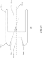
- the interior surface of the inner elbow region 115-a is curved to provide a gradual transition between the straight passage segment 111 and the angled passage segment 112. As shown in Figure 13 , the curved interior surface of the inner elbow region 115-a provides a similar removal of material at the inner elbow region 115-a of the angled sleeve 110. Removed portion 118-r shown in phantom for reference illustrates the amount of material removed from the inner elbow region 115-a when the inner surface of this inner elbow region 115-a is curved. As in the previously described embodiment, the removed material at the inner elbow region 115-a of the junction 115 improves the mobility of the driver shaft 120 in and out of the angled sleeve 110.
- an opening is provided at the inner elbow region 115-a of the junction 115. As shown in Figure 14 , the opening is located at the inner elbow region 115-a and is intermediate the distal end of the straight passage segment 111 and the angled passage segment 112. Removed portion 118-r is shown in phantom for reference illustrate the amount of material removed from the inner elbow region 115-a to create the opening. As in the previously described embodiments, the removed material at the inner elbow region 115-a of the junction 115 improves the mobility of the driver shaft 120 in and out of the angled sleeve 110.
- any other manner in which the vertex formed by the inner surface of the straight passage segment 111 meeting the inner surface of the angled passage segment 112 is removed can be used in order to provide the additional space at the inner elbow region 115-a needed to improve the mobility of the driver shaft 120 through the angled sleeve 110.
- the angled sleeve 110 also includes a tool bit opening 114 near the distal end 110-b of the angled sleeve 110.
- the tool bit opening 114 is provided generally at the outer elbow region 115-b and can extend across both a portion of the straight passage segment 111 and the angled passage segment 112.
- the shape of the tool bit opening 114 is shaped to allow tool bits to be inserted and removed from the angled sleeve 110 and is shown as generally oval or tear drop shaped, although other shapes are usable.
- the tool bit opening 114 is sized and positioned such that the longitudinal axis of a tool bit can be oriented parallel to the axis 116 of the angled passage segment 112 and passed directly into the angled passage segment 112 via the tool bit opening 114.
- the tool bit opening 114 is positioned on the generally straight passage segment 111 at the outer elbow region 115-b such that the distal end 121-b of the drive shaft 120 freely moves past the tool bit opening 114.
- an opening 114 is not required for positioning a tool bit at the distal 110-b end of the angled sleeve.
- the dimensions of the tool bit are sufficiently small that the tool bit can be inserted into the angled sleeve 110 at the proximal end 110-a and moved through the angled sleeve 110, including through the junction 115, until is reaches the distal end 110-b of the angled sleeve.
- the angled sleeve 110 further includes a sleeve cap 200.
- the sleeve cap 200 generally includes a cylindrical body 210 having a proximal end 210-a and a distal end 210-b and a cylindrical hollow passage extending from the proximal end 210-a to the distal end 210-b.
- the hollow passage can be dimensioned such that the driver shaft 120 can pass through the hollow passage.
- the outer diameter of the cylindrical body is smaller at the distal end 210-b than at the proximal end 210-a.
- the diameter of the cylindrical body at the distal end 210-b is generally equal to or less than the diameter of the hollow passage at the proximal end 110-a of the angled sleeve 110 so that the distal end 210-a can be inserted into the hollow passage at the proximal end 110-a of the angled sleeve 110.
- the distal end 210-b can also include threading 211 that is designed to mate with threading located in the hollow passage at the proximal end 110-a of the angled sleeve 110. In this manner, the sleeve cap 200 may be secured to the angled sleeve 110.
- the cylindrical body210 may have a diameter that is approximately equal to the outer diameter of the angled sleeve 110 at the proximal end 110-a. In this manner, the proximal end 210-a of the cylindrical body 210 can be coextensive and flush mounted with the proximal end 110-a of the angled sleeve 110 when the distal end 210-b of the cylindrical body 210 is inserted into the proximal end 110-a of the angled sleeve.
- the driver shaft 120 suitable for use with the angled sleeve 110 is shown.
- the driver shaft 120 includes a shaft body 121, a U-joint head 122, a block 123, and a fork 124.
- the U-joint head 122, block 123, and fork 124 combine to form the tool bit engagement assembly 125.
- the shaft body 121 is generally provided to move the tool bit engagement assembly 125 through the angled sleeve 110, including moving the tool bit engagement assembly 125 from the opening at the proximal end 110-a of the angled sleeve 110 to the angled passage segment 112 at the distal end 110-b of the angled sleeve 110.
- the tool bit engagement assembly 125 is configured to engage with a tool bit deposited into the angled passage segment 112 of the angled sleeve 110 via the tool bit opening 114 and provide for the rotation of the tool bit by rotating the shaft body 121.
- the shaft body 121 has a generally elongated cylindrical shape. At the proximal end 121-a of the shaft body 121, a portion of the cylindrical shape may be removed to form a planar surface. At the distal end 121-b of the shaft body 121, the U-joint head 122 is connected to the shaft body 121.
- the U-joint head 122 may be connected to the shaft body 121 using any suitable means, including forming the U-joint head 122 as part of a unitary body with the shaft body 121.
- the U-joint head 122 is connected with the shaft body 121 such that it does not rotate or pivot relative to the shaft body 121.
- the diameter of the shaft body 121 expands to form a disc stopper 126.
- the location and size of the disc stopper 126 is configured such that the disc stopper 126 will work in conjunction with the internal configuration of the angled sleeve 110 to prevent the driver shaft 120 from moving axially past a selected point within the angled sleeve 110.
- the interior region of the handle 113 has an increased diameter relative to the diameter of the hollow passage way extending through the remainder of the angled sleeve 110.
- a ledge 113-a is thus formed where the diameter of the internal passage transitions from the large diameter to the smaller diameter.
- the disc stopper 126 abuts against this ledge 113-a to prevent further movement of the driver shaft 120 axially towards the distal end 110-b of the angled sleeve 110.
- the dimensions of the driver shaft 120, including the location of the disc stopper 126 can be selected such that when the disc stopper 126 abuts the ledge 113-a, the distal end 121-b of the driver shaft 120 (including the tool bit engagement assembly 125) is positioned at the junction 115 of the angled sleeve 110.
- the U-joint head 122 includes a cylindrical body 122-a which tapers down at its distal end to two arms 122-b and 122-c that extend away from the cylindrical body 122-a and the shaft body 121.
- the two arms 122-b and 122-c extend from the periphery of the cylindrical body 122-a and are oriented generally parallel to one another and to the axis of the shaft body 121.
- the two arms 122-b and 122-c are relatively thin such that a gap 122-d is defined between the two arms 122-b and 122-c that is only slightly smaller than the diameter of the cylindrical body 122-a.
- a bore 122-e is provided at the rounded terminal end of each arm 122-b and 122-c.
- the bores 122-e are aligned with one another such that one pin 122-f (shown in Figure 5A ) can be inserted through each bores and extend into the gap 122-d at an orientation perpendicular to the axis of the shaft body 121.
- the gap 122-d in the U-joint head 122 is sized and configured so that a block 123 can be positioned within the gap 122-d and between the two arms 122-b and 122-c.
- the block 123 is pivotal about an axis defined by the pins 122-f.
- the block 123 has a generally cube shape.
- Two opposing sides 123-a and 123-b of the block 123 are substantially rounded, which results in the edges of the block that contact the rounded sides 123-a and 123-b also be rounded.
- the remaining sides 123-c, 123-d, 123-e, and 123-f of the block are planar. As shown in Figure 7 , planar side 123-c is opposite planar side 123-e and planar side 123-d is opposite planar side 123-f.
- a through hole 123-g extends from planar side 123-c to planar side 123-e and a through hole 123-h extends from planar side 123-d to planar side 123-f.
- the through holes 123-g and 123-h are configured to receive pins or rods that will allow the fork 124 to pivot along two perpendicular axes when the tool bit engagement assembly 125 is assembled.
- the fork 124 includes a body portion 124-a having a generally cylindrical shape and two arms 124-b and 124-c that extend away from the body portion 124-a.
- the two arms 124-b and 124-c extend from the periphery of the body portion 124-a and are oriented generally parallel to one another and to the axis of the body portion 124-a.
- the two arms 124-b and 124-c are relatively thin such that a gap 124-e is defined between the two arms 124-b and 124-c that is only slightly smaller than the diameter of the body portion 124-a.
- a bore 124-f is provided at the rounded terminal end of each arm 124-b and 124-c.
- the bores 124-f are aligned with one another such that a rod 122-g (shown in Figure 5A ) can be inserted through both bores 124-f and extend across the gap 124-e at an orientation perpendicular to the axis of the body portion 124-a.
- the gap 124-e in the fork 124 is sized and configured so that the block 123 can be positioned within the gap and between the two arms 124-b and 124-c.
- the fork 124 is pivotal about an axis defined by the rod 122-g.
- the set of pins can be used to form a pivotal connection between the fork 124 and the block 123 and the rod can be used to form a pivotal connection between the block 123 and the U-joint head 122.
- the fork 124 further includes a recess 124-d (or female socket) in the body portion 124-a.
- the opening of the recess 124-d is at the end of the body portion 124-a opposite where the arms 124-b and 124-c extend away from the body portion 124.
- the recess 124-d is configured for receiving the male end of a tool bit that is engaged by the fork 124.
- the recess can have any shape suitable for engaging a tool bit. As shown in Figure 8 , the recess has a hexagonal shape for receiving a hexagonal-shaped male end of a tool bit. As shown in Figure 15 , the recess 124-d has angled sidewalls 124-d-1.
- the sidewalls 124-d-1 are form an angle DELTA with the longitudinal axis 124-g of the fork 124. In some embodiments, the angle DELTA is in the range of from 0.1° to 5°.
- the angled side walls 124-d-1 of the recess 124-d can improve the ease with which a tool bit engagement body can be disengaged from the recess 124-d.
- the assembled tool bit engagement assembly 125 is shown.
- the block 123 is inserted into the gap 122-d of the U-joint head 122 such that two opposing planar sides of the block 123 are flush with the arms 122-b and 122-c of the U-joint head 124.
- the through hole of the block 123 is aligned with the bores 122-e in the arms 122-b and 122-c so that a short pin can be inserted through each hole 122-e and partially into the opening of the through hole 123-h adjacent each respective bore 122-e. This pivotably secures the block 123 to the U-joint head 122.
- the fork 124 is positioned so that the block 123 is inserted into the gap 124-e in the fork 124. As shown in Figures 5A and 5B , the fork 124 is oriented such that the arms 124-b and 124-c are flush mounted with the remaining planar sides of the block 123 (i.e., the planar sides of the block 124 not flush mounted with the arms 122-b and 122-c of the U-joint head 122.
- the bores 124-f in the arms 124-b and 124-c are aligned with the through hole 123-g in the block 123 and a single rod extends through both bores 124-f and the through hole 123-g to pivotably secure the fork 124 to the block 123.
- the fork 124 is able to pivot in two directions, namely about the axis of each of the two through holes in the block 123.
- the fork 124 can be rotated by rotating the shaft body 121 even when the fork 124 is positioned at an angle within the angled passage segment 112 of the angled sleeve 110. Accordingly, when the fork 124 is engaged with a tool bit, the rotation of the shaft body 121 results in the rotation of the tool bit and the ability to drive a screw with the tool bit.
- a tool bit 130 is provided to be used in conjunction with the angled sleeve 110 and the driver shaft 120. As discussed above, the tool bit 130 is passed through the tool bit opening 114 in the angled sleeve 110 so that the tool bit 130 can pass directly into and through the angled passage segment 112 of the angled sleeve 110. The tool bit 130 is dimensioned so that it will fit through both tool bit opening 114 and the angled passage segment 112.
- the tool bit 130 generally includes an engagement body 131, a stopper 132, and a tool body 133, which is shown as a drill bit in the exemplary embodiment.
- the engagement body 131 (or male connector) is located at the proximal end of the tool bit 130 and is shaped and dimensioned to cooperatively engage with the recess 124-d (or female socket) of the fork 124.
- the engagement body 131 has a hexagonal shape that is suitable for engaging with the hexagonal recess 124-d shown in Figure 8 .
- the engagement body 131 will also have a length approximately equal to the depth of the recess 124-d.
- the engagement body is not limited to a hexagonal shape. Any shape can be used provided that the shape of the engagement body 131 suitably mates with the recess 124-d so that rotation of the fork 124 results in corresponding rotation of the tool bit 130.
- the engagement body 131 has a plurality of side walls 131-a to 131-f for the hexagonal engagement body shown.
- Each of the side walls, including side wall 131-a and 131-b, of the engagement body 131 are angled slightly to assist with the insertion and removal of the male body into the female socket.
- the tool bit 130 has an axis 134.
- the side walls of the engagement body 131 form an angle GAMMA with the axis 134.
- the angle GAMMA can be in the range of from 0.1° to 5°.
- the tool bit 130 includes a stopper 132.
- the stopper 132 is located intermediate the proximal and distal ends of the tool bit 130 and has a generally disc shape.
- the stopper 132 has a diameter that is larger than the remainder of the tool bit 130.
- the stopper is generally used to prevent that tool bit 130 from sliding completely out of the distal end of the angled passage segment 112 of the angled sleeve 110.
- the distal end of the angled passage segment 112 has an opening 112-a that is large enough for the tool body 133 to pass through, but which is smaller than the stopper 132.
- the stopper 132 abuts against the walls of the opening 112-a and prevents the tool bit 132 from passing all the way out of the angled passage segment 112.
- the location of the stopper 132 along the length of the tool bit 130 can be selected based on the dimensions of the angled passage segment 112 so that the stopper 132 allows a sufficient amount of the tool body 133 to pass through the angled passage segment 112 and positions the engagement body 131 within the angled passage segment 112 such that the fork 124 can engage with the engagement body 131.
- the tool body 133 is generally located at the distal end of the tool bit 130.
- the exact shape of the tool body 133 is generally not limited and can include any of a variety of different tool shapes, including, but not limited to, screws, drills and taps.
- Figure 9 shows a tool body 133 that is a drill.
- Figure 11 illustrates a tool bit 130 having a tool body 133 that is a solid tip driver.
- the fork 124 replaces the recess with an engagement body and the tool bit replaces the engagement body with a recess.
- the fork 124 includes the male engagement body and the tool bit includes the female engagement body.
- a tool bit 300 is shown having a recess 310 instead of an engagement body.
- the angled instrument assembly can be used by first providing a passage to the target site or an area near the target site in the bone.
- the passage can be created using any methods known to those of ordinary skill in the art.
- the angled sleeve can then be prepared for insertion into passage.
- the angled sleeve is prepared by inserting the selected tool bit into angled passage segment via the tool bit opening and then inserting the driver shaft into the angled sleeve.
- the tool bit can be inserted into the angled passage section such that the stopper on the tool bit rests against the opening in the distal end of the angled passage segment and the majority of the tool body of the tool bit extends out of the opening in the distal end of the angled passage segment.
- the driver shaft can be inserted into the angled sleeve such that the tool bit engagement assembly is engaged with the tool bit positioned at the distal end of the angled sleeve.
- the stopper on the driver shaft will engage with the ledge at the distal end of the handle region to ensure that the driver shaft is not inserted too far into the angled sleeve.
- the junction deflects the fork and causes it to pivot so that it can become aligned in parallel with the axis of the angled passage segment. This can help to ensure that the recess in the fork is properly aligned to receive the engagement body of the tool bit.
- the configuration of the tool bit opening including its size and locations, ensures that the fork does not get caught on the distal end of the opening as it is being moved through the junction.
- the angled sleeve can be moved through the passage and towards the target site.
- the driver shaft can be rotated in order to rotate the fork and the engaged tool bit.
- the driver shaft is rotated by using the handle provided at the proximal end of the angled sleeve.
- This handle may include an internal mechanism that engages with the driver shaft inserted into the angled sleeve so that rotating the handle on the angled sleeve also rotates the driver shaft.
- the rotating action can be carried out manually or with the assistance of a powered drill.
- the rotating motion can be carried out for as long as necessary to carry out the desired action (e.g., drilling a hole or driving a screw).
Landscapes
- Health & Medical Sciences (AREA)
- Surgery (AREA)
- Life Sciences & Earth Sciences (AREA)
- Orthopedic Medicine & Surgery (AREA)
- Biomedical Technology (AREA)
- Public Health (AREA)
- Veterinary Medicine (AREA)
- Engineering & Computer Science (AREA)
- Nuclear Medicine, Radiotherapy & Molecular Imaging (AREA)
- Heart & Thoracic Surgery (AREA)
- Medical Informatics (AREA)
- Molecular Biology (AREA)
- Animal Behavior & Ethology (AREA)
- General Health & Medical Sciences (AREA)
- Dentistry (AREA)
- Oral & Maxillofacial Surgery (AREA)
- Surgical Instruments (AREA)
- Earth Drilling (AREA)
- Dental Tools And Instruments Or Auxiliary Dental Instruments (AREA)
Claims (13)
- Ensemble d'instrument coudé (100), comprenant :un manchon coudé (110) ayant un passage creux s'étendant à travers celui-ci, comprenant :un segment de passage droit (111) ayant un premier axe longitudinal (117) et une surface intérieure ;un segment de passage coudé (112) ayant un deuxième axe longitudinal (116) et une surface intérieure ; etune zone de jonction (115) reliant le segment de passage droit au segment de passage coudé, la zone de jonction comprenant un coude intérieur (115-a) et un coude extérieur (115-b) ;dans lequel le deuxième axe forme un premier angle (a) avec le premier axe ;
etun arbre d'entraînement (120) configuré pour être reçu dans le passage creux du manchon coudé, comprenant :un corps d'arbre allongé (121) ayant une extrémité proximale et une extrémité distale ; etun ensemble d'engagement de mèche (125) couplé au niveau de l'extrémité distale du corps d'arbre allongé ; etcaractérisé en ce que,une surface intérieure du coude intérieur comprend une surface qui forme un deuxième angle (β) avec le premier axe, le deuxième angle étant inférieur au premier angle (a) ; etle manchon coudé comprend en outre une ouverture de mèche (114) située au niveau du coude extérieur de la zone de jonction et configurée pour permettre à une mèche (130) d'être passée dans le segment de passage coudé le long du deuxième axe. - Ensemble d'instrument coudé selon la revendication 1, comprenant en outre :
une mèche (130) comprenant une extrémité proximale et une extrémité distale, l'extrémité proximale comprenant un corps d'engagement configuré pour s'engager avec l'ensemble d'engagement de mèche. - Ensemble d'instrument coudé selon la revendication 2, dans lequel le corps d'engagement comprend trois parois latérales planes ou plus et une paroi d'extrémité et la surface de chacune des parois latérales planes forme un angle avec un axe de la mèche, l'angle se situant dans la plage de 1° à 5°.
- Ensemble d'instrument coudé selon la revendication 2, dans lequel l'ensemble d'engagement de mèche comprend :
une fourche (124) ayant une extrémité proximale et une extrémité distale et dans lequel l'extrémité distale de la fourche comprend un évidement configuré pour recevoir le corps d'engagement de mèche. - Ensemble d'instrument coudé selon la revendication 4, dans lequel l'ensemble d'engagement de mèche est configuré pour permettre à la fourche de pivoter le long de deux axes orientés perpendiculairement.
- Ensemble d'instrument coudé selon la revendication 2, dans lequel l'ensemble d'engagement de mèche comprend :une tête d'articulation en U (122) ayant un corps (122-a) et deux bras (122-b, 122-c) s'étendant à l'écart du corps dans une direction distale et définissant un espace (124-d) entre les deux bras ;une fourche (124) ayant un corps (124-a), deux bras (124-b, 124-c) s'étendant à l'écart du corps dans une direction proximale et définissant un espace (124-e) entre les deux bras, et un évidement (124-d) formé dans une extrémité distale de la fourche ; etun bloc de pivot positionné simultanément dans l'espace de la tête d'articulation en U et de la fourche, le bloc de pivot ayant un premier trou traversant (123-g) s'étendant entre une première paire de côtés opposés du bloc et un second trou traversant (123- h) s'étendant entre une seconde paire de côtés opposés du bloc ;dans lequel une tige de connexion (122-g) s'étend à travers le premier trou traversant et s'accouple avec les deux bras de la tête d'articulation en U pour connecter de manière pivotante le bloc de pivot à la tête d'articulation en U ; etdans lequel une broche de connexion (122-f) est insérée dans chaque ouverture du second trou traversant et s'accouple avec l'un des deux bras de la fourche pour connecter de manière pivotante le bloc de pivot à la fourche.
- Ensemble d'instrument coudé selon la revendication 1, dans lequel le manchon coudé comprend en outre une poignée (113) située à une extrémité proximale du manchon coudé actionnable pour faire tourner l'arbre d'entraînement lorsque l'arbre d'entraînement est reçu dans le passage creux du manchon coudé.
- Ensemble d'instrument coudé selon la revendication 1, dans lequel la surface intérieure du coude intérieur comprend un premier segment de surface, un deuxième segment de surface et un troisième segment de surface, le deuxième segment de surface étant situé entre le premier segment de surface et le troisième segment de surface ;
dans lequel le premier segment de surface est orienté à 0°, le troisième segment de surface est orienté à un angle dans la plage de 1° à 45°, et le deuxième segment de surface est orienté à un angle supérieur au premier segment de surface mais inférieur au troisième segment de surface. - Ensemble d'instrument coudé selon la revendication 8, dans lequel le segment de passage coudé a un diamètre uniforme sur toute la longueur du segment de passage coudé.
- Ensemble d'instrument coudé selon la revendication 9, dans lequel le segment de passage coudé comprend une ouverture distale ayant un diamètre qui est inférieur au diamètre du segment de passage coudé.
- Ensemble d'instrument coudé selon la revendication 8, dans lequel le segment de passage coudé a un axe qui est orienté parallèlement au troisième segment de surface de la surface intérieure du coude intérieur.
- Ensemble d'instrument coudé selon la revendication 8, dans lequel le segment de passage droit comprend une poignée couplée fonctionnellement à une extrémité proximale du segment de passage droit.
- Ensemble d'instrument coudé selon la revendication 8, dans lequel la section de passage droit a un axe qui est orienté parallèlement au premier segment de surface de la surface intérieure du coude interne.
Applications Claiming Priority (2)
| Application Number | Priority Date | Filing Date | Title |
|---|---|---|---|
| US13/913,158 US9339321B2 (en) | 2013-06-07 | 2013-06-07 | Angled instrument assembly |
| PCT/US2014/041252 WO2014197776A1 (fr) | 2013-06-07 | 2014-06-06 | Ensemble d'instrument coudé |
Publications (3)
| Publication Number | Publication Date |
|---|---|
| EP3003186A1 EP3003186A1 (fr) | 2016-04-13 |
| EP3003186A4 EP3003186A4 (fr) | 2017-02-22 |
| EP3003186B1 true EP3003186B1 (fr) | 2021-07-14 |
Family
ID=52006064
Family Applications (1)
| Application Number | Title | Priority Date | Filing Date |
|---|---|---|---|
| EP14808233.2A Active EP3003186B1 (fr) | 2013-06-07 | 2014-06-06 | Ensemble d'instrument coudé |
Country Status (3)
| Country | Link |
|---|---|
| US (3) | US9339321B2 (fr) |
| EP (1) | EP3003186B1 (fr) |
| WO (1) | WO2014197776A1 (fr) |
Families Citing this family (25)
| Publication number | Priority date | Publication date | Assignee | Title |
|---|---|---|---|---|
| US9339321B2 (en) | 2013-06-07 | 2016-05-17 | Zimmer Biomet Spine, Inc. | Angled instrument assembly |
| CN104688295B (zh) * | 2015-01-14 | 2017-09-08 | 雷东 | 一种带角度调节功能的医用磨削动力装置 |
| WO2017222011A1 (fr) * | 2016-06-22 | 2017-12-28 | 株式会社東鋼 | Foret |
| CN108523961B (zh) * | 2017-03-03 | 2021-01-26 | 财团法人工业技术研究院 | 微创手术器械 |
| TWI642401B (zh) | 2017-03-03 | 2018-12-01 | 財團法人工業技術研究院 | 微創手術器械 |
| US11806250B2 (en) | 2018-02-22 | 2023-11-07 | Warsaw Orthopedic, Inc. | Expandable spinal implant system and method of using same |
| CN108514441B (zh) * | 2018-04-28 | 2024-06-18 | 美茵(北京)医疗器械研发有限公司 | 一种血管打孔组件以及打孔器 |
| CN110151251B (zh) * | 2019-05-30 | 2024-05-17 | 中国人民解放军总医院 | 一种髁间截骨钻 |
| US11793558B2 (en) | 2019-08-30 | 2023-10-24 | K2M, Inc. | All in one plate holder and spring loaded awl |
| US11234712B2 (en) | 2019-10-25 | 2022-02-01 | Warsaw Orthopedic, Inc. | Medical access device |
| US12171439B2 (en) * | 2020-11-05 | 2024-12-24 | Warsaw Orthopedic, Inc. | Protected drill |
| US11833059B2 (en) | 2020-11-05 | 2023-12-05 | Warsaw Orthopedic, Inc. | Expandable inter-body device, expandable plate system, and associated methods |
| US11617658B2 (en) | 2020-11-05 | 2023-04-04 | Warsaw Orthopedic, Inc. | Expandable inter-body device, system and method |
| US11517443B2 (en) | 2020-11-05 | 2022-12-06 | Warsaw Orthopedic, Inc. | Dual wedge expandable implant, system and method of use |
| US11638653B2 (en) * | 2020-11-05 | 2023-05-02 | Warsaw Orthopedic, Inc. | Surgery instruments with a movable handle |
| US11963881B2 (en) | 2020-11-05 | 2024-04-23 | Warsaw Orthopedic, Inc. | Expandable inter-body device, system, and method |
| US12239544B2 (en) | 2020-11-05 | 2025-03-04 | Warsaw Orthopedic, Inc. | Rhomboid shaped implants |
| US12318308B2 (en) | 2020-11-05 | 2025-06-03 | Warsaw Orthopedic, Inc. | Dual expandable inter-body device |
| US12121453B2 (en) | 2020-11-05 | 2024-10-22 | Warsaw Orthopedic, Inc. | Dual wedge expandable implant with eyelets, system, and method of use |
| US12440349B2 (en) | 2021-11-01 | 2025-10-14 | Warsaw Orthopedic, Inc. | Expandable interbody implant and breakoff screw |
| US11612499B2 (en) | 2021-06-24 | 2023-03-28 | Warsaw Orthopedic, Inc. | Expandable interbody implant |
| US12295865B2 (en) | 2021-06-24 | 2025-05-13 | Warsaw Orthopedic, Inc. | Expandable interbody implant and corresponding inserter |
| WO2022271280A1 (fr) | 2021-06-24 | 2022-12-29 | Warsaw Orthopedic, Inc. | Implant intervertébral extensible et outil chirurgical correspondant |
| US12485019B2 (en) | 2021-06-24 | 2025-12-02 | Warsaw Orthopedic, Inc. | Parallel jaw inserter |
| US12533241B2 (en) | 2023-05-16 | 2026-01-27 | Warsaw Orthopedic, Inc. | Distracting and angling expandable interbody device |
Family Cites Families (11)
| Publication number | Priority date | Publication date | Assignee | Title |
|---|---|---|---|---|
| ATE232064T1 (de) | 1996-07-31 | 2003-02-15 | Synthes Ag | Vorrichtung zum fixieren abgebrochener hüftgelenkköpfe |
| EP1410763A1 (fr) * | 2002-10-14 | 2004-04-21 | Waldemar Link (GmbH & Co.) | Instrument chirurgical de façonnage |
| US20040172036A1 (en) | 2003-02-27 | 2004-09-02 | Donald Dye | Angled acetabular reamer and method of use |
| US8348959B2 (en) | 2006-03-23 | 2013-01-08 | Symmetry Medical Manufacturing, Inc. | Angled surgical driver |
| US20080188854A1 (en) | 2007-01-05 | 2008-08-07 | University Of Florida Research Foundation, Inc. | Surgical Anchor Delivery System |
| US7762813B2 (en) * | 2007-08-03 | 2010-07-27 | Young Dental Manufacturing Company 1 Llc | Disposable prophylaxis angle |
| US20090088770A1 (en) * | 2007-10-01 | 2009-04-02 | Warsaw Orthopedic, Inc. | Angled surgical drivers and methods of use |
| US8740983B1 (en) * | 2009-11-11 | 2014-06-03 | Nuvasive, Inc. | Spinal fusion implants and related methods |
| US9066814B2 (en) * | 2010-08-02 | 2015-06-30 | Ulrich Medical Usa, Inc. | Implant assembly having an angled head |
| US9080611B2 (en) | 2010-12-01 | 2015-07-14 | Howmedica Osteonics Corp. | Drive tool having an angled connector |
| US9339321B2 (en) | 2013-06-07 | 2016-05-17 | Zimmer Biomet Spine, Inc. | Angled instrument assembly |
-
2013
- 2013-06-07 US US13/913,158 patent/US9339321B2/en not_active Expired - Fee Related
-
2014
- 2014-06-06 WO PCT/US2014/041252 patent/WO2014197776A1/fr not_active Ceased
- 2014-06-06 EP EP14808233.2A patent/EP3003186B1/fr active Active
-
2016
- 2016-05-16 US US15/155,592 patent/US9763675B2/en not_active Expired - Fee Related
-
2017
- 2017-09-18 US US15/706,985 patent/US20180021047A1/en not_active Abandoned
Non-Patent Citations (1)
| Title |
|---|
| None * |
Also Published As
| Publication number | Publication date |
|---|---|
| WO2014197776A1 (fr) | 2014-12-11 |
| EP3003186A1 (fr) | 2016-04-13 |
| US20140364855A1 (en) | 2014-12-11 |
| EP3003186A4 (fr) | 2017-02-22 |
| US20180021047A1 (en) | 2018-01-25 |
| US9763675B2 (en) | 2017-09-19 |
| US20160331385A1 (en) | 2016-11-17 |
| US9339321B2 (en) | 2016-05-17 |
Similar Documents
| Publication | Publication Date | Title |
|---|---|---|
| EP3003186B1 (fr) | Ensemble d'instrument coudé | |
| US8123780B2 (en) | Dismantable medical forceps system | |
| CN104352264B (zh) | 一种多自由度腹腔镜手术器械 | |
| CN110074842B (zh) | 与驱动器、钻头和套管一起使用以钻入骨中的适配器 | |
| US20020082606A1 (en) | Drill guide | |
| EP3113696B1 (fr) | Instrument de guidage séparable pour implant anatomique | |
| WO2018160269A1 (fr) | Dispositif orientable pour le traitement de maladies liées aux tissus durs et la chirurgie mini-invasive | |
| JP2008509753A5 (fr) | ||
| JP2015513979A (ja) | 骨ねじおよび自己保持型ドライバ | |
| US10265194B2 (en) | Insertion instrument with articulating wrist | |
| US20040098006A1 (en) | Medical handpiece and cutting tool therefor | |
| BR112013025667B1 (pt) | broca cirúrgica e método para carregar uma broca de corte em uma broca cirúrgica | |
| JP4542362B2 (ja) | 内視鏡処置システム | |
| CN211749904U (zh) | 可视变向手术动力装置 | |
| AU2019275477B2 (en) | Surgical handle | |
| KR101860906B1 (ko) | 가이드 와이어 및 이를 포함하는 연성 카테터 | |
| CN111166516B (zh) | 一种具备伸缩杆的可变向种植修复螺丝刀组件 | |
| CN211271106U (zh) | 一种带有轨道剪的万向改锥 | |
| JP7695717B2 (ja) | 手術器械、医療器具セット、及び移植方法 | |
| CN110063799B (zh) | 经皮脊柱内镜助控器 | |
| CN204618307U (zh) | 微创手术用多角度钻铣工具 | |
| US12310645B1 (en) | Pedicle screw remover | |
| JP2005118415A (ja) | インプラント装着用デバイス | |
| JP4597260B1 (ja) | インプラント窩の形成用の治具、及び、手術具 | |
| CN121533805A (zh) | 一种克氏针折弯器 |
Legal Events
| Date | Code | Title | Description |
|---|---|---|---|
| PUAI | Public reference made under article 153(3) epc to a published international application that has entered the european phase |
Free format text: ORIGINAL CODE: 0009012 |
|
| 17P | Request for examination filed |
Effective date: 20160107 |
|
| AK | Designated contracting states |
Kind code of ref document: A1 Designated state(s): AL AT BE BG CH CY CZ DE DK EE ES FI FR GB GR HR HU IE IS IT LI LT LU LV MC MK MT NL NO PL PT RO RS SE SI SK SM TR |
|
| AX | Request for extension of the european patent |
Extension state: BA ME |
|
| DAX | Request for extension of the european patent (deleted) | ||
| A4 | Supplementary search report drawn up and despatched |
Effective date: 20170125 |
|
| RIC1 | Information provided on ipc code assigned before grant |
Ipc: A61B 17/88 20060101AFI20170119BHEP Ipc: A61B 17/16 20060101ALI20170119BHEP Ipc: A61B 17/84 20060101ALI20170119BHEP |
|
| GRAP | Despatch of communication of intention to grant a patent |
Free format text: ORIGINAL CODE: EPIDOSNIGR1 |
|
| STAA | Information on the status of an ep patent application or granted ep patent |
Free format text: STATUS: GRANT OF PATENT IS INTENDED |
|
| INTG | Intention to grant announced |
Effective date: 20201214 |
|
| GRAS | Grant fee paid |
Free format text: ORIGINAL CODE: EPIDOSNIGR3 |
|
| GRAA | (expected) grant |
Free format text: ORIGINAL CODE: 0009210 |
|
| STAA | Information on the status of an ep patent application or granted ep patent |
Free format text: STATUS: THE PATENT HAS BEEN GRANTED |
|
| AK | Designated contracting states |
Kind code of ref document: B1 Designated state(s): AL AT BE BG CH CY CZ DE DK EE ES FI FR GB GR HR HU IE IS IT LI LT LU LV MC MK MT NL NO PL PT RO RS SE SI SK SM TR |
|
| REG | Reference to a national code |
Ref country code: GB Ref legal event code: FG4D |
|
| REG | Reference to a national code |
Ref country code: IE Ref legal event code: FG4D |
|
| REG | Reference to a national code |
Ref country code: DE Ref legal event code: R096 Ref document number: 602014078783 Country of ref document: DE |
|
| REG | Reference to a national code |
Ref country code: AT Ref legal event code: REF Ref document number: 1410047 Country of ref document: AT Kind code of ref document: T Effective date: 20210815 |
|
| REG | Reference to a national code |
Ref country code: LT Ref legal event code: MG9D |
|
| REG | Reference to a national code |
Ref country code: NL Ref legal event code: MP Effective date: 20210714 |
|
| REG | Reference to a national code |
Ref country code: AT Ref legal event code: MK05 Ref document number: 1410047 Country of ref document: AT Kind code of ref document: T Effective date: 20210714 |
|
| PG25 | Lapsed in a contracting state [announced via postgrant information from national office to epo] |
Ref country code: HR Free format text: LAPSE BECAUSE OF FAILURE TO SUBMIT A TRANSLATION OF THE DESCRIPTION OR TO PAY THE FEE WITHIN THE PRESCRIBED TIME-LIMIT Effective date: 20210714 Ref country code: SE Free format text: LAPSE BECAUSE OF FAILURE TO SUBMIT A TRANSLATION OF THE DESCRIPTION OR TO PAY THE FEE WITHIN THE PRESCRIBED TIME-LIMIT Effective date: 20210714 Ref country code: RS Free format text: LAPSE BECAUSE OF FAILURE TO SUBMIT A TRANSLATION OF THE DESCRIPTION OR TO PAY THE FEE WITHIN THE PRESCRIBED TIME-LIMIT Effective date: 20210714 Ref country code: ES Free format text: LAPSE BECAUSE OF FAILURE TO SUBMIT A TRANSLATION OF THE DESCRIPTION OR TO PAY THE FEE WITHIN THE PRESCRIBED TIME-LIMIT Effective date: 20210714 Ref country code: FI Free format text: LAPSE BECAUSE OF FAILURE TO SUBMIT A TRANSLATION OF THE DESCRIPTION OR TO PAY THE FEE WITHIN THE PRESCRIBED TIME-LIMIT Effective date: 20210714 Ref country code: PT Free format text: LAPSE BECAUSE OF FAILURE TO SUBMIT A TRANSLATION OF THE DESCRIPTION OR TO PAY THE FEE WITHIN THE PRESCRIBED TIME-LIMIT Effective date: 20211115 Ref country code: NO Free format text: LAPSE BECAUSE OF FAILURE TO SUBMIT A TRANSLATION OF THE DESCRIPTION OR TO PAY THE FEE WITHIN THE PRESCRIBED TIME-LIMIT Effective date: 20211014 Ref country code: NL Free format text: LAPSE BECAUSE OF FAILURE TO SUBMIT A TRANSLATION OF THE DESCRIPTION OR TO PAY THE FEE WITHIN THE PRESCRIBED TIME-LIMIT Effective date: 20210714 Ref country code: LT Free format text: LAPSE BECAUSE OF FAILURE TO SUBMIT A TRANSLATION OF THE DESCRIPTION OR TO PAY THE FEE WITHIN THE PRESCRIBED TIME-LIMIT Effective date: 20210714 Ref country code: AT Free format text: LAPSE BECAUSE OF FAILURE TO SUBMIT A TRANSLATION OF THE DESCRIPTION OR TO PAY THE FEE WITHIN THE PRESCRIBED TIME-LIMIT Effective date: 20210714 Ref country code: BG Free format text: LAPSE BECAUSE OF FAILURE TO SUBMIT A TRANSLATION OF THE DESCRIPTION OR TO PAY THE FEE WITHIN THE PRESCRIBED TIME-LIMIT Effective date: 20211014 |
|
| PG25 | Lapsed in a contracting state [announced via postgrant information from national office to epo] |
Ref country code: PL Free format text: LAPSE BECAUSE OF FAILURE TO SUBMIT A TRANSLATION OF THE DESCRIPTION OR TO PAY THE FEE WITHIN THE PRESCRIBED TIME-LIMIT Effective date: 20210714 Ref country code: LV Free format text: LAPSE BECAUSE OF FAILURE TO SUBMIT A TRANSLATION OF THE DESCRIPTION OR TO PAY THE FEE WITHIN THE PRESCRIBED TIME-LIMIT Effective date: 20210714 Ref country code: GR Free format text: LAPSE BECAUSE OF FAILURE TO SUBMIT A TRANSLATION OF THE DESCRIPTION OR TO PAY THE FEE WITHIN THE PRESCRIBED TIME-LIMIT Effective date: 20211015 |
|
| REG | Reference to a national code |
Ref country code: DE Ref legal event code: R097 Ref document number: 602014078783 Country of ref document: DE |
|
| PG25 | Lapsed in a contracting state [announced via postgrant information from national office to epo] |
Ref country code: DK Free format text: LAPSE BECAUSE OF FAILURE TO SUBMIT A TRANSLATION OF THE DESCRIPTION OR TO PAY THE FEE WITHIN THE PRESCRIBED TIME-LIMIT Effective date: 20210714 |
|
| PLBE | No opposition filed within time limit |
Free format text: ORIGINAL CODE: 0009261 |
|
| STAA | Information on the status of an ep patent application or granted ep patent |
Free format text: STATUS: NO OPPOSITION FILED WITHIN TIME LIMIT |
|
| PG25 | Lapsed in a contracting state [announced via postgrant information from national office to epo] |
Ref country code: SM Free format text: LAPSE BECAUSE OF FAILURE TO SUBMIT A TRANSLATION OF THE DESCRIPTION OR TO PAY THE FEE WITHIN THE PRESCRIBED TIME-LIMIT Effective date: 20210714 Ref country code: SK Free format text: LAPSE BECAUSE OF FAILURE TO SUBMIT A TRANSLATION OF THE DESCRIPTION OR TO PAY THE FEE WITHIN THE PRESCRIBED TIME-LIMIT Effective date: 20210714 Ref country code: RO Free format text: LAPSE BECAUSE OF FAILURE TO SUBMIT A TRANSLATION OF THE DESCRIPTION OR TO PAY THE FEE WITHIN THE PRESCRIBED TIME-LIMIT Effective date: 20210714 Ref country code: EE Free format text: LAPSE BECAUSE OF FAILURE TO SUBMIT A TRANSLATION OF THE DESCRIPTION OR TO PAY THE FEE WITHIN THE PRESCRIBED TIME-LIMIT Effective date: 20210714 Ref country code: CZ Free format text: LAPSE BECAUSE OF FAILURE TO SUBMIT A TRANSLATION OF THE DESCRIPTION OR TO PAY THE FEE WITHIN THE PRESCRIBED TIME-LIMIT Effective date: 20210714 Ref country code: AL Free format text: LAPSE BECAUSE OF FAILURE TO SUBMIT A TRANSLATION OF THE DESCRIPTION OR TO PAY THE FEE WITHIN THE PRESCRIBED TIME-LIMIT Effective date: 20210714 |
|
| 26N | No opposition filed |
Effective date: 20220419 |
|
| PG25 | Lapsed in a contracting state [announced via postgrant information from national office to epo] |
Ref country code: IT Free format text: LAPSE BECAUSE OF FAILURE TO SUBMIT A TRANSLATION OF THE DESCRIPTION OR TO PAY THE FEE WITHIN THE PRESCRIBED TIME-LIMIT Effective date: 20210714 |
|
| PGFP | Annual fee paid to national office [announced via postgrant information from national office to epo] |
Ref country code: GB Payment date: 20220623 Year of fee payment: 9 Ref country code: DE Payment date: 20220621 Year of fee payment: 9 |
|
| PG25 | Lapsed in a contracting state [announced via postgrant information from national office to epo] |
Ref country code: MC Free format text: LAPSE BECAUSE OF FAILURE TO SUBMIT A TRANSLATION OF THE DESCRIPTION OR TO PAY THE FEE WITHIN THE PRESCRIBED TIME-LIMIT Effective date: 20210714 |
|
| REG | Reference to a national code |
Ref country code: CH Ref legal event code: PL |
|
| REG | Reference to a national code |
Ref country code: BE Ref legal event code: MM Effective date: 20220630 |
|
| PG25 | Lapsed in a contracting state [announced via postgrant information from national office to epo] |
Ref country code: LU Free format text: LAPSE BECAUSE OF NON-PAYMENT OF DUE FEES Effective date: 20220606 Ref country code: LI Free format text: LAPSE BECAUSE OF NON-PAYMENT OF DUE FEES Effective date: 20220630 Ref country code: IE Free format text: LAPSE BECAUSE OF NON-PAYMENT OF DUE FEES Effective date: 20220606 Ref country code: FR Free format text: LAPSE BECAUSE OF NON-PAYMENT OF DUE FEES Effective date: 20220630 Ref country code: CH Free format text: LAPSE BECAUSE OF NON-PAYMENT OF DUE FEES Effective date: 20220630 |
|
| PG25 | Lapsed in a contracting state [announced via postgrant information from national office to epo] |
Ref country code: BE Free format text: LAPSE BECAUSE OF NON-PAYMENT OF DUE FEES Effective date: 20220630 |
|
| REG | Reference to a national code |
Ref country code: DE Ref legal event code: R119 Ref document number: 602014078783 Country of ref document: DE |
|
| GBPC | Gb: european patent ceased through non-payment of renewal fee |
Effective date: 20230606 |
|
| PG25 | Lapsed in a contracting state [announced via postgrant information from national office to epo] |
Ref country code: HU Free format text: LAPSE BECAUSE OF FAILURE TO SUBMIT A TRANSLATION OF THE DESCRIPTION OR TO PAY THE FEE WITHIN THE PRESCRIBED TIME-LIMIT; INVALID AB INITIO Effective date: 20140606 |
|
| PG25 | Lapsed in a contracting state [announced via postgrant information from national office to epo] |
Ref country code: MK Free format text: LAPSE BECAUSE OF FAILURE TO SUBMIT A TRANSLATION OF THE DESCRIPTION OR TO PAY THE FEE WITHIN THE PRESCRIBED TIME-LIMIT Effective date: 20210714 Ref country code: DE Free format text: LAPSE BECAUSE OF NON-PAYMENT OF DUE FEES Effective date: 20240103 Ref country code: CY Free format text: LAPSE BECAUSE OF FAILURE TO SUBMIT A TRANSLATION OF THE DESCRIPTION OR TO PAY THE FEE WITHIN THE PRESCRIBED TIME-LIMIT Effective date: 20210714 Ref country code: GB Free format text: LAPSE BECAUSE OF NON-PAYMENT OF DUE FEES Effective date: 20230606 |
|
| PG25 | Lapsed in a contracting state [announced via postgrant information from national office to epo] |
Ref country code: TR Free format text: LAPSE BECAUSE OF FAILURE TO SUBMIT A TRANSLATION OF THE DESCRIPTION OR TO PAY THE FEE WITHIN THE PRESCRIBED TIME-LIMIT Effective date: 20210714 |
|
| PG25 | Lapsed in a contracting state [announced via postgrant information from national office to epo] |
Ref country code: MT Free format text: LAPSE BECAUSE OF FAILURE TO SUBMIT A TRANSLATION OF THE DESCRIPTION OR TO PAY THE FEE WITHIN THE PRESCRIBED TIME-LIMIT Effective date: 20210714 |