EP3003162B1 - Method and apparatus for obtaining elastic feature of object - Google Patents
Method and apparatus for obtaining elastic feature of object Download PDFInfo
- Publication number
- EP3003162B1 EP3003162B1 EP14852061.2A EP14852061A EP3003162B1 EP 3003162 B1 EP3003162 B1 EP 3003162B1 EP 14852061 A EP14852061 A EP 14852061A EP 3003162 B1 EP3003162 B1 EP 3003162B1
- Authority
- EP
- European Patent Office
- Prior art keywords
- shear wave
- signal
- sub
- ultrasound
- ultrasound signal
- Prior art date
- Legal status (The legal status is an assumption and is not a legal conclusion. Google has not performed a legal analysis and makes no representation as to the accuracy of the status listed.)
- Not-in-force
Links
Images

Classifications
-
- A—HUMAN NECESSITIES
- A61—MEDICAL OR VETERINARY SCIENCE; HYGIENE
- A61B—DIAGNOSIS; SURGERY; IDENTIFICATION
- A61B8/00—Diagnosis using ultrasonic, sonic or infrasonic waves
- A61B8/13—Tomography
- A61B8/14—Echo-tomography
-
- G—PHYSICS
- G01—MEASURING; TESTING
- G01S—RADIO DIRECTION-FINDING; RADIO NAVIGATION; DETERMINING DISTANCE OR VELOCITY BY USE OF RADIO WAVES; LOCATING OR PRESENCE-DETECTING BY USE OF THE REFLECTION OR RERADIATION OF RADIO WAVES; ANALOGOUS ARRANGEMENTS USING OTHER WAVES
- G01S7/00—Details of systems according to groups G01S13/00, G01S15/00, G01S17/00
- G01S7/52—Details of systems according to groups G01S13/00, G01S15/00, G01S17/00 of systems according to group G01S15/00
- G01S7/52017—Details of systems according to groups G01S13/00, G01S15/00, G01S17/00 of systems according to group G01S15/00 particularly adapted to short-range imaging
- G01S7/52023—Details of receivers
- G01S7/52036—Details of receivers using analysis of echo signal for target characterisation
- G01S7/52042—Details of receivers using analysis of echo signal for target characterisation determining elastic properties of the propagation medium or of the reflective target
-
- A—HUMAN NECESSITIES
- A61—MEDICAL OR VETERINARY SCIENCE; HYGIENE
- A61B—DIAGNOSIS; SURGERY; IDENTIFICATION
- A61B8/00—Diagnosis using ultrasonic, sonic or infrasonic waves
- A61B8/52—Devices using data or image processing specially adapted for diagnosis using ultrasonic, sonic or infrasonic waves
- A61B8/5215—Devices using data or image processing specially adapted for diagnosis using ultrasonic, sonic or infrasonic waves involving processing of medical diagnostic data
-
- G—PHYSICS
- G01—MEASURING; TESTING
- G01S—RADIO DIRECTION-FINDING; RADIO NAVIGATION; DETERMINING DISTANCE OR VELOCITY BY USE OF RADIO WAVES; LOCATING OR PRESENCE-DETECTING BY USE OF THE REFLECTION OR RERADIATION OF RADIO WAVES; ANALOGOUS ARRANGEMENTS USING OTHER WAVES
- G01S7/00—Details of systems according to groups G01S13/00, G01S15/00, G01S17/00
- G01S7/52—Details of systems according to groups G01S13/00, G01S15/00, G01S17/00 of systems according to group G01S15/00
- G01S7/52017—Details of systems according to groups G01S13/00, G01S15/00, G01S17/00 of systems according to group G01S15/00 particularly adapted to short-range imaging
- G01S7/52019—Details of transmitters
- G01S7/5202—Details of transmitters for pulse systems
- G01S7/52022—Details of transmitters for pulse systems using a sequence of pulses, at least one pulse manipulating the transmissivity or reflexivity of the medium
-
- A—HUMAN NECESSITIES
- A61—MEDICAL OR VETERINARY SCIENCE; HYGIENE
- A61B—DIAGNOSIS; SURGERY; IDENTIFICATION
- A61B8/00—Diagnosis using ultrasonic, sonic or infrasonic waves
- A61B8/48—Diagnostic techniques
- A61B8/485—Diagnostic techniques involving measuring strain or elastic properties
Description
- One or more exemplary embodiments relate to a medical diagnosis field, and more particularly, to a method and apparatus for obtaining an elastic feature of an object by using an ultrasound apparatus.
- A general ultrasound apparatus is a non-invasive test apparatus and is used to show structural details, internal tissues, and the flow of liquids in a body. An ultrasound apparatus transmits an ultrasound signal to an object and generates an ultrasound image of the object by using a response signal reflected from the object. The ultrasound image is mainly presented as a B mode image which is generated as a function of a reflection coefficient which varies based on a difference in impedance between tissues. However, an object such as a malignant tumor, for which the variation in the reflection coefficient may be relatively small as compared to surrounding tissues, is difficult to observe in the B mode image.
- In particular, it is often difficult to discern, in the B mode image, a difference in dispersion efficiency between a normal tissue and an abnormal tissue. Accordingly, methods of distinguishing a normal tissue and an abnormal tissue by obtaining an elastic feature of a medium when an external pressure is applied or not applied to the medium have been suggested.
-
U.S. Patent No. 5,810,731 discloses a method of obtaining an elastic feature of an object by transmitting a focused ultrasound signal to an object to induce shear waves in the object and measuring a shear wave feature.US/2013/0211253 A1 discloses on-axis shear wave characterization with ultrasound. - However, in the disclosed methods, shear waves are not induced in an area which is perpendicular to a position of the object where a user locates a probe, that is, an area where a focused ultrasound signal is propagated, because the focused ultrasound signal is transmitted to the object in a direction which is perpendicular to the probe in order to induce shear waves in a direction which is perpendicular to the direction in which the focused ultrasound signal is propagated. In this aspect, even when a user locates a probe near an object in order to measure an elastic feature of a partial area of the object, according to a method of the related art, an elastic feature of a part of the object which is located under the position where the probe is located may not be obtained.
- Further, according to the methods of the related art, since the shear waves are induced in the object by using the focused ultrasound signal, there may be an increased
risk due to a high sound pressure of the focused ultrasound signal. - One or more exemplary embodiments include an apparatus and method for accurately and quickly obtaining an elastic feature of an object.
- According to a first aspect, the invention relates to a method for obtaining an elastic feature of an object as specified in claim 1.
- According to a second aspect, the invention relates to a method for obtaining an elastic feature of an object as specified in claim 9.
- According to a third aspect, the invention relates to a non-transitory computer readable storage medium as specified in claim 12.
- According to a fourth aspect, the invention relates to a non-transitory computer readable storage medium as specified in claim 13.
- According to a fifth aspect, the invention relates to an ultrasound apparatus as specified in claim 14.
- According to a sixth aspect, the invention relates to an ultrasound apparatus as specified in claim 15.
-
-
FIG. 1 illustrates an ultrasound apparatus which is configured for transmitting a first push ultrasound signal and a first grating lobe signal to an object, according to an exemplary embodiment; -
FIG. 2 is a flowchart which illustrates a method for obtaining an elastic feature of an object, according to an exemplary embodiment; -
FIG. 3 illustrates an exemplary method by which an ultrasound apparatus induces a first shear wave in the object, according to an exemplary embodiment; -
FIG. 4 illustrates an exemplary method by which an ultrasound apparatus induces a first shear wave in the object, according to another exemplary embodiment; -
FIG. 5 is a flowchart which illustrates a method for obtaining an elastic feature of an object, according to another exemplary embodiment; -
FIG. 6 illustrates a method by which the ultrasound apparatus measures a propagation velocity of the first shear wave, according to an exemplary embodiment; -
FIG. 7 is a flowchart which illustrates a method for obtaining an elastic feature of an object, according to another exemplary embodiment; and -
FIG. 8 is a block diagram which illustrates a structure of an ultrasound apparatus, according to an exemplary embodiment. - According to one or more exemplary embodiments, a method for obtaining an elastic feature of an object includes inducing a first shear wave in the object by transmitting a first push ultrasound signal which is generated by a probe of an ultrasound apparatus and a first grating lobe signal which relates to the first push ultrasound signal toward the object, transmitting a first tracking ultrasound signal to an area of the object where the first shear wave has propagated, and receiving, from the object, a first reflection signal which relates to the first tracking ultrasound signal, measuring a first shear wave parameter which indicates a shear wave characteristic of the first shear wave based on the first reflection signal, and obtaining an elastic feature of the object by using the measured first shear wave parameter characterised in that the strength of the grating lobe signal is equal to the strength of the first push ultrasound signal and the step of inducing the first shear wave in the object further comprises synthesizing a first sub-shear wave induced in the object of the first push ultrasound signal and a second sub-shear wave induced in the object by the first grating lobe signal.
- The first push ultrasound signal may include an unfocused ultrasound signal.
- In the inducing of the first shear wave, the first shear wave may be induced in the object by transmitting a plurality of first push ultrasound signals and a plurality of first grating lobe signals which respectively relate to the first push ultrasound signals, both pluralities having a same steering angle, toward the object by using a plurality of elements which are included in the probe.
- The inducing the first shear wave may include transmitting the first push ultrasound signal toward the object by steering the first push ultrasound signal at a first steering angle.
- The method may further include inducing a second shear wave in the object by transmitting a second push ultrasound signal which is steered at a second steering angle that is different from the first steering angle and a second grating lobe signal which relates to the second push ultrasound signal toward the object, transmitting a second tracking ultrasound signal to an area of the object where the second shear wave has propagated and receiving, from the object, a second reflection signal which relates to the second tracking ultrasound signal, and measuring a second shear wave parameter which indicates a shear wave characteristic of the second shear wave based on the second reflection signal. In the above method, the obtaining of the elastic feature of the object comprises using the measured first shear wave parameter and the measured second shear wave parameter to determine an average parameter value and obtaining the elastic feature of the object by using the determined average parameter value.
- The receiving the first reflection signal may include transmitting the first tracking ultrasound signal a plurality of times to an area where the first shear wave has propagated and receiving, from the object, a plurality of first reflection signals which relate to the plurality of transmissions of the first tracking ultrasound signal, and the measuring the first shear wave parameter may include measuring the first shear wave parameter by applying a cross-correlation to the received plurality of first reflection signals.
- The obtaining the elastic feature of the object may further include generating an image of an elasticity of the object by mapping the elastic feature to at least one from among a black and white scale and a color scale.
- The transmitting the tracking ultrasound signal may include transmitting the first tracking ultrasound signal to a first position where the first shear wave has propagated and transmitting a second tracking ultrasound signal to a second position where the first shear wave has propagated, and the receiving the first reflection signal may include receiving the first reflection signal which relates to the first tracking ultrasound signal from the first position and receiving a second reflection signal which relates to the second tracking ultrasound signal from the second position. The measuring the first shear wave parameter may include measuring a first phase of the first shear wave from the first reflection signal and measuring a second phase of the first shear wave from the second reflection signal, and measuring a propagation velocity of the first shear wave by using a phase difference between the measured first phase and the measured second phase and by using a distance between the first position and the second position.
- According to one or more exemplary embodiments, a method for obtaining an elastic feature of an object includes inducing a first sub-shear wave in the object by transmitting a first push ultrasound signal which is generated by a probe of an ultrasound apparatus, and inducing a second sub-shear wave in the object by transmitting a first grating lobe signal which relates to the first push ultrasound signal toward the object, wherein the strength of the grating signal is equal to the strength of the first push ultrasound signal, transmitting a first tracking ultrasound signal to an area of the object where the first and second sub-shear waves have propagated, and receiving, from the object, a first reflection signal which relates to the first tracking ultrasound signal, measuring a first shear wave parameter of the first sub-shear wave and a second shear wave parameter of the second sub-shear wave based on the received first reflection signal, and using the measured first shear wave parameter of the first sub-shear wave and the measured second shear wave parameter of the second sub-shear wave to determine an average parameter value, and obtaining an elastic feature of the object by using the determined average parameter value.
- The first push ultrasound signal may include an unfocused ultrasound signal.
- The measuring the first shear wave parameter of the first sub-shear wave and the second shear wave parameter of the second sub-shear wave may include blocking a first component portion of the first reflection signal which relates to the first sub-shear wave by applying a first directional filter to the first reflection signal, and blocking a second component portion of the first reflection signal which relates to the second sub-shear wave by applying a second directional filter to the first reflection signal, and measuring the first shear wave parameter of the first sub-shear wave based on a result of the blocking the second component portion of the first reflection signal, and measuring the second shear wave parameter of the second sub-shear wave based on a result of the blocking the first component portion of the first reflection signal
- According to one or more exemplary embodiments, a non-transitory computer readable storage medium having stored thereon a program which, when executed by a computer of an ultrasound apparatus, performs the method of obtaining an elastic feature of an object includes inducing a first shear wave in the object by transmitting a first push ultrasound signal which is generated by a probe of the ultrasound apparatus and a first grating lobe signal which relates to the first push ultrasound signal toward the object, transmitting a first tracking ultrasound signal to an area of the object where the first shear wave has propagated, and receiving, from the object, a first reflection signal which relates to the first tracking ultrasound signal, measuring a first shear wave parameter which indicates a shear wave characteristic of the first shear wave based on the first reflection signal, and obtaining an elastic feature of the object by using the first shear wave parameter characterized in that the strength of the grating lobe signal is equal to the strength of the first push ultrasound signal and the first step of inducing the first shear sound wave in the objection further comprises synthesizing a first sub-shear wave induced in the object by the first push ultrasound signal and a second sub-shear wave induced in the object by the first grating lobe signal.
- According to one or more exemplary embodiments, a non-transitory computer readable storage medium having stored thereon a program which, when executed by a computer of an ultrasound apparatus, performs the method of obtaining an elastic feature of an object includes inducing a first sub-shear wave in the object by transmitting a first push ultrasound signal which is generated by a probe of the ultrasound apparatus and inducing a second sub-shear wave in the object by transmitting a first grating lobe signal which relates to the first push ultrasound signal toward the object, wherein the strength of the grating lobe signal is equal to the strength of the first push ultrasound signal, transmitting a first tracking ultrasound signal to an area of the object where the first and second sub-shear waves have propagated, and receiving, from the object, a first reflection signal which relates to the first tracking ultrasound signal, measuring a first shear wave parameter of the first sub-shear wave and a second shear wave parameter of the second sub-shear wave based on the received first reflection signal, and using the measured first shear wave parameter of the first sub-shear wave and the measured second shear wave parameter of the second sub-shear wave to determine an average parameter value, and obtaining an elastic feature of the object by using the determined average parameter value.
- According to one or more exemplary embodiments, an ultrasound apparatus may include a shear wave inducer configured to induce a first shear wave in an object by transmitting a first push ultrasound signal which is generated by a probe of the ultrasound apparatus and a first grating lobe signal which relates to the first push ultrasound signal toward the object, a shear wave detector configured to transmit a first tracking ultrasound signal to an area of the object where the first shear wave has propagated and to receive a first reflection signal which relates to the first tracking ultrasound signal from the object, and a controller configured to measure a first shear wave parameter which indicates a shear wave characteristic of the first shear wave based on the received first reflection signal and to obtain an elastic feature of the object by using the measured first shear wave parameter characterized in that the shear wave inducer is configured to induce the grating lobe signal having a strength equal to the strength of the first push ultrasound signal and the shear wave inducer is configured to induce the first shear wave in the object by synthesizing a first sub-shear wave generated by the first push ultrasound signal and a second sub-shear wave generated by the first grating lobe signal.
- According to one or more exemplary embodiments, an ultrasound apparatus includes a shear wave inducer configured to induce a first sub-shear wave in an object by transmitting a first push ultrasound signal which is generated by a probe of an ultrasound apparatus and to induce a second sub-shear wave in the object by transmitting a first grating lobe signal which relates to the first push ultrasound signal toward the object, wherein the strength of the grating lobe signal is equal to the strength of the first push ultrasound signal, a shear wave detector configured to transmit a first tracking ultrasound signal to an area of the object where the first and second sub-shear waves have propagated, and to receive, from the object, a first reflection signal which relates to the first tracking ultrasound signal, and a controller configured to measure a first shear wave parameter of the first sub-shear wave and to measure a second shear wave parameter of the second sub-shear wave based on the received first reflection signal, to use the measured first shear wave parameter of the first sub-shear wave and the measured second shear wave parameter of the second sub-shear wave to determine an average parameter value, and to obtain an elastic feature of the object by using the determined average parameter value.
- Reference will now be made in detail to exemplary embodiments, examples of which are illustrated in the accompanying drawings, wherein like reference numerals refer to like elements throughout. In this regard, the present exemplary embodiments may have different forms and should not be construed as being limited to the descriptions set forth herein. Accordingly, the exemplary embodiments are merely described below, by referring to the figures, to explain aspects of the present disclosure. As used herein, the term "and/or" includes any and all combinations of one or more of the associated listed items. Expressions such as "at least one of," when preceding a list of elements, modify the entire list of elements and do not modify the individual elements of the list.
- The terms such as "∼ portion", "∼ unit", "∼ module", and "∼ block" stated in the specification may signify a unit which is configured to process at least one function or operation, and the unit may be embodied by hardware such as a field-programmable gate array (FPGA) or an application-specific integrated circuit (ASIC), software, or a combination of hardware and software. However, the unit may be configured to be located in a storage medium to be addressed or configured to be able to operate one or more processors. Accordingly, the unit as an example includes constituent elements such as software constituent elements, object-oriented software constituent elements, class constituent elements, and task constituent elements, processes, functions, attributes, procedures, sub-routines, segments of program codes, drivers, firmware, microcodes, circuits, data, a database, data structures, tables, arrays, and variables. The constituent elements and functions provided by the "units" may be combined into a smaller number of constituent elements and units or may be further divided into additional constituent elements and units. Accordingly, the present exemplary embodiments are not limited by a specific combination of hardware and software.
- In the present specification, an "image" may signify multi-dimensional data which is formed of discrete image elements, for example, pixels in a two-dimensional (2D) image and/or voxels in a three-dimensional (3D) image. For example, an image may include an ultrasound image.
- Further, in the present specification, an "object" may include any one or more of a human, an animal, or a part of a human or an animal. For example, an object may include organs such as the liver, the heart, the womb, the brain, a breast, the abdomen, etc., and/or blood vessels. In addition, an object may include a phantom that signifies matter which has a volume that approximates the intensity and effective atomic number of a living thing, and may include a sphere phantom which has a property similar to that of a human body.
- Still further, in the present specification, a "user" may be a doctor, a nurse, a clinical pathologist, a medical imaging expert, a technician who fixes a medical apparatus, and/or any other suitable type of user, but the exemplary embodiments are not limited thereto.
-
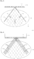
FIG. 1 illustrates anultrasound apparatus 100 which is configured for transmitting a firstpush ultrasound signal 113 and a firstgrating lobe signal 115 to anobject 10, according to an exemplary embodiment. Referring toFIG. 1 , theultrasound apparatus 100 may include aprobe 110 that transmits an ultrasound signal toward theobject 10 and receives a reflection signal which is reflected from theobject 10. Theultrasound apparatus 100 may generate an image of theobject 10 by using the received reflection signal. Theprobe 110 may include an array probe which includes a plurality ofelements 111 that are separately and/or independently controllable by theultrasound apparatus 100. - The
ultrasound apparatus 100, according to the present exemplary embodiment, transmits the firstpush ultrasound signal 113 and the firstgrating lobe signal 115 that is generated to correspond to the firstpush ultrasound signal 113 toward theobject 10 via theprobe 110 in order to induce a first shear wave which is generated by the firstpush ultrasound signal 113 and the firstgrating lobe signal 115 in theobject 10. - The first
grating lobe signal 115 is a signal which propagates in a non-axial direction and which is generated by theprobe 110. In general, a grating lobe signal is a signal that should be removed because it reduces a lateral direction contrast aspect of an ultrasound image. The grating lobe signal may be weakened by reducing the width of an element of theprobe 110 by an amount that makes the element width less than or equal
to 1/2 of the wavelength of an ultrasound signal. - In the present exemplary embodiment, however, by designing the
probe 110 such that the strength of the grating lobe signal equals the strength of a main beam, rather than weakening or removing the grating lobe signal generated by theprobe 110, an induced shear wave in theobject 10 may result from the transmission of the grating lobe signal. - The first
push ultrasound signal 113 may include an unfocused ultrasound signal. Theultrasound apparatus 100, according to the present exemplary embodiment, transmits the firstpush ultrasound signal 113 toward theobject 10 so that a risk due to a high sound pressure may be reduced. - Further, the
ultrasound apparatus 100, according to the present exemplary embodiment, may transmit the firstpush ultrasound signal 113 toward theobject 10 by steering the firstpush ultrasound signal 113 at a first steering angle "a". The steering angle signifies an angle between apreset reference axis 117 and a direction in which an ultrasound signal propagates. For example, theultrasound apparatus 100 may set the first steering angle "a" of the firstpush ultrasound signal 113 to be within a range of between 0° and 90°. Accordingly, a shear wave may be induced in an area of theobject 10 that is perpendicular to a position where theprobe 110 is located. - In addition, the
ultrasound apparatus 100, according to the present exemplary embodiment, may generate the firstgrating lobe signal 115 such that a steering angle "b" of the firstgrating lobe signal 115 is different from the first steering angle "a" of the firstpush ultrasound signal 113 by a predetermined angle. For example, the steering angle "b" of the firstgrating lobe signal 115 may be set to an angle which is determined by subtracting an angular measure of the first steering angle "a" of the firstpush ultrasound signal 113 from 180°. Accordingly, the firstpush ultrasound signal 113 and the firstgrating lobe signal 115 may be transmitted toward theobject 10 in the symmetrical directions with respect to a center of avertical axis 118 of theprobe 110. The steering angle "b" of the firstgrating lobe signal 115 may be controlled by adjusting the pitch and width of an element of theprobe 110. -
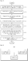
FIG. 2 is a flowchart which illustrates a method for obtaining an elastic feature of theobject 10, according to an exemplary embodiment. Referring toFIG. 2 , in operation S210, theultrasound apparatus 100 transmits, toward theobject 10, the firstpush ultrasound signal 113 which is generated by theprobe 110 and the firstgrating lobe signal 115 which relates to the firstpush ultrasound signal 113. As described above, the firstpush ultrasound signal 113 may include an unfocused ultrasound signal. Theultrasound apparatus 100 may transmit the firstpush ultrasound signal 113 toward theobject 10 by steering the firstpush ultrasound signal 113 by the first steering angle "a". - In operation S220, the
ultrasound apparatus 100 induces in the object 10 a first shear wave which is generated by the firstpush ultrasound signal 113 and the firstgrating lobe signal 115. The first shear wave which is induced in theobject 10 will be described below with reference toFIG. 3 . - In operation S230, the
ultrasound apparatus 100 transmits a first tracking ultrasound signal to an area of theobject 10 where the first shear wave has propagated. - In operation S240, the
ultrasound apparatus 100 receives a first reflection signal from theobject 10 which relates to the first tracking ultrasound signal. - In operation S250, the
ultrasound apparatus 100 measures a first shear wave parameter which indicates a shear wave characteristic of the first shear wave, based on the first reflection signal which is received from theobject 10. The first shear wave parameter may include at least one from among a propagation velocity of the first shear wave and an attenuation coefficient of the first shear wave. - The propagation velocity Vs of the first shear wave may be obtained by applying Equation 1, and the attenuation coefficient α of the first shear wave may be obtained by applying Equation 2. In Equations 1 and 2, "R" and "X" respectively are a real number component and an imaginary number of an acoustic impedance of the
object 10, ρ is a density of theobject 10, and ω is an angular frequency of the first shear wave.

- Further, the
ultrasound apparatus 100, according to the present exemplary embodiment, may measure the first shear wave parameter by transmitting the first tracking ultrasound signal multiple times toward the area where the first shear wave has propagated, receiving, from theobject 10, a corresponding plurality of first reflection signals which respectively relate to the plurality of transmissions of the first tracking ultrasound signal toward theobject 10, and then applying a cross-correlation to the plurality of received first reflection signals. - In addition to the above-described methods, the first shear wave parameter of the first shear wave which is induced in the
object 10 may be measured by any one or more of a variety of methods within a scope that is well-known to those of ordinary skill in the art. - In operation S260, the
ultrasound apparatus 100 may obtain an elastic feature of theobject 10 by using the first shear wave parameter. The elastic feature of theobject 10 may include at least one from among a shear modulus, a Young's modulus, and a shear viscosity of theobject 10. A shear modulus G of theobject 10 may be obtained by applying Equation 3. Young's modulus E of theobject 10 may be obtained by applying Equation 4. A shear viscosity η of theobject 10 may be obtained by applying Equation 5.


- The
ultrasound apparatus 100, according to the present exemplary embodiment, may generate an image of an elasticity of theobject 10 by mapping the elastic feature of theobject 10 to either or both of a black and white scale and a color scale, and output a generated image of the elasticity via a display (not shown). -
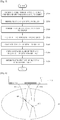
FIG. 3 illustrates an exemplary method by which theultrasound apparatus 100 induces a first shear wave in theobject 10, according to an exemplary embodiment. Referring toFIG. 3 , a firstsub-shear wave 114 which is induced in theobject 10 by the firstpush ultrasound signal 113 propagates in a direction A that is perpendicular to the direction in which the firstpush ultrasound signal 113 propagates. In addition, a secondsub-shear wave 116 which is induced in theobject 10 by the firstgrating lobe signal 115 propagates in a direction B that is perpendicular to the direction in which the firstgrating lobe signal 115 propagates. - When the steering angle of the first
grating lobe signal 115 is set to be an angle which is determined by subtracting an angular measure of the steering angle of the firstpush ultrasound signal 113 from 180°, x-axis components of the firstsub-shear wave 114 induced by the firstpush ultrasound signal 113 and the secondsub-shear wave 116 induced by the firstgrating lobe signal 115 are offset with each other, and only y-axis components thereof remain. As a result, in an area where both the first and secondsub-shear waves sub-shear waves ultrasound apparatus 100, according to the present exemplary embodiment, may obtain an elastic feature of theobject 10 by measuring the first shear wave parameter of the first shear wave that propagates in the direction C. -
FIG. 4 illustrates an exemplary method by which theultrasound apparatus 100 induces a first shear wave in theobject 10, according to another exemplary embodiment. Referring toFIG. 4 , theultrasound apparatus 100, according to the present exemplary embodiment, may transmit a plurality of first push ultrasound signals 113 and a corresponding plurality of first grating lobe signals 115 which respectively relate to the first push ultrasound signals 113, both pluralities having a same steering angle, by using a plurality ofelements 111, thereby inducing in the object 10 a first shear wave that is generated by the first push ultrasound signals 113 and the first grating lobe signals 115. - When a first shear wave is induced in the
object 10 by using only one firstpush ultrasound signal 113 and one firstgrating lobe signal 115, the strength of the first shear wave may be weak, and therefore, in the present exemplary embodiment, the first shear wave is induced in theobject 10 by using at least two of the first push ultrasound signals 113 and at least two of the first grating lobe signals 115. IN order to enable the firstsub-shear waves 114 induced by the first push ultrasound signals 113 to overlap with each other, an interval between the first push ultrasound signals 113 is adjusted. -
FIG. 5 is a flowchart which illustrates a method for obtaining an elastic feature of theobject 10, according to another exemplary embodiment. The method for obtaining an elastic feature of theobject 10 which is illustrated inFIG. 5 may be performed instead of operation S260 ofFIG. 2 . - In operation S510, the
ultrasound apparatus 100 transmits, to theobject 10, a second push ultrasound signal that is steered at a second steering angle which is different from the first steering angle of the firstpush ultrasound signal 113, and also transmits a second grating lobe signal which corresponds to the second push ultrasound signal. - In operation S520, the
ultrasound apparatus 100 induces, in theobject 10, a second shear wave that is generated by the second push ultrasound signal and the second grating lobe signal. - In operation S530, the
ultrasound apparatus 100 transmits a second tracking ultrasound signal to an area of theobject 10 where the second shear wave has propagated. - In operation S540, the
ultrasound apparatus 100 receives a second reflection signal which relates to the second tracking ultrasound signal from theobject 10. - In operation S550, the
ultrasound apparatus 100 measures a second shear wave parameter which indicates a shear wave characteristic of the second shear wave, based on the received second reflection signal. The method for measuring the shear wave parameter based on the reflection signal has already been described above with reference toFIG. 2 , and thus, a detailed description thereof will be omitted here. - In operation S560, the
ultrasound apparatus 100 determines an average parameter value of the first shear wave parameter measured in operation S250 ofFIG. 2 and the second shear wave parameter. Theultrasound apparatus 100 may determine the average parameter value of the first and second shear wave parameters by applying a respective weight to each of the first and second shear wave parameters. - In operation S570, the
ultrasound apparatus 100 obtains an elastic feature of theobject 10 by using the determined average parameter value. - According to a method for obtaining an elastic feature of the
object 10 according to another exemplary embodiment, because the elastic feature of theobject 10 is obtained after determining an average parameter value of the first shear wave parameter of the first shear wave which is induced by the firstpush ultrasound signal 113 and the firstgrating lobe signal 115 and the second shear wave parameter of the second shear wave which is induced by the second push ultrasound signal and the second grating lobe signal, the elastic feature of theobject 10 may be relatively more accurately obtained. -
FIG. 6 illustrates a method by which theultrasound apparatus 100 measures a propagation velocity of the first shear wave, according to an exemplary embodiment. Reference will be made toFIG. 6 to describe an exemplary method other than the above-described method for measuring the first shear wave parameter of the first shear wave inFIG. 2 . - The
ultrasound apparatus 100, according to the present exemplary embodiment, may transmit a firsttracking ultrasound signal 610 to afirst position 601 in an area where the first shear wave has propagated, and receive a first reflection signal which is reflected from thefirst position 601. Next, theultrasound apparatus 100 may transmit a secondtracking ultrasound signal 630 to asecond position 603 in an area where the first shear wave has propagated, and receive a second reflection signal which is reflected from thesecond position 603. Theultrasound apparatus 100 may measure a first phase of the first shear wave from the first reflection signal and a second phase of the first shear wave from the second reflection signal. - In detail, the
ultrasound apparatus 100 measures a first phase of the first shear wave that passes through thefirst position 601 by using the first reflection signal, and measures a second phase of the first shear wave that passes through thesecond position 603 by using the second reflection signal. Theultrasound apparatus 100 may measure a propagation velocity of the first shear wave as the first shear wave parameter by using a phase difference between the measured first and second phases and a distance d between the first andsecond positions - For example, the
ultrasound apparatus 100 may obtain a propagation velocity Cs of the first shear wave by applying Equation 6. In Equation 6, ω is an angular frequency of the first shear wave, Δr is a distance d between the first and second positions, and Δϕ is a phase difference between the first and second phases.
- Although in the above description the first shear wave parameter of the first shear wave induced in the
object 10 is measured, it is possible to obtain an elastic feature of theobject 10 by measuring a first shear wave parameter of the firstsub-shear wave 114 which is induced in theobject 10 by the firstpush ultrasound signal 113 and by measuring a second shear wave parameter of the secondsub-shear wave 116 which is induced in theobject 10 by the firstgrating lobe signal 115 and using the measured first and second shear wave parameters. -
FIG. 7 is a flowchart which illustrates a method for obtaining an elastic feature of theobject 10, according to another exemplary embodiment. - In operation S710, the
ultrasound apparatus 100 transmits, to theobject 10, the firstpush ultrasound signal 113 which is generated by theprobe 110 of theultrasound apparatus 100 and the corresponding first gratinglobe signal 115 which relates to the firstpush ultrasound signal 113. In operation S720, theultrasound apparatus 100 induces, in theobject 10, the firstsub-shear wave 114 which is generated by the firstpush ultrasound signal 113 and the secondsub-shear wave 116 which is generated by the firstgrating lobe signal 115. In operation S730, theultrasound apparatus 100 transmits a first tracking ultrasound signal to an area of theultrasound apparatus 100 where the firstsub-shear wave 114 and the secondsub-shear wave 116 have propagated. In operation S740, theultrasound apparatus 100 receives, from theobject 10, a first reflection signal which relates to the first tracking ultrasound signal. - In operation S750, the
ultrasound apparatus 100 measures a first shear wave parameter of the firstsub-shear wave 114 and a second shear wave parameter of the secondsub-shear wave 116 based on the received first reflection signal. Because the first and secondsub-shear waves object 10, theultrasound apparatus 100 may measure the respective first and second shear wave parameters of the first and secondsub-shear waves - For example, the
ultrasound apparatus 100 may block a first component portion of the first reflection signal, which first component portion corresponds to the firstsub-shear wave 114, by applying a first directional filter to the first reflection signal which is received from theobject 10, and may block a second component portion of the first reflection signal, which second component portion corresponds to the secondsub-shear wave 116, by applying a second directional filter to the first reflection signal. Next, theultrasound apparatus 100 may measure the first shear wave parameter of the firstsub-shear wave 114 based on a result of the blocking the second component portion of the first reflection signal, and may measure the second shear wave parameter of the secondsub-shear wave 116 based on a result of the blocking the first component portion of the first reflection signal. Because the directional filter is well-known to those of ordinary skill in the art, a detailed description thereof will be omitted herein. - In operation S760, the
ultrasound apparatus 100 determines an average parameter value of the first shear wave parameter of the firstsub-shear wave 114 and the second shear wave parameter of the secondsub-shear wave 116. Theultrasound apparatus 100 may apply a respective weight to each of the first shear wave parameter of the firstsub-shear wave 114 and the second shear wave parameter of the secondsub-shear wave 116, and then may determine an average value of the first shear wave parameter of the firstsub-shear wave 114 to which a first weight is applied and the second shear wave parameter of the secondsub-shear wave 116 to which a second weight is applied. - In operation S770, the
ultrasound apparatus 100 may obtain an elastic feature of theobject 10 by using the average parameter value which is determined in operation S760. - According to a method for obtaining an elastic feature of the
object 10 according to another exemplary embodiment, theultrasound apparatus 100 may measure the first shear wave parameter of the firstsub-shear wave 114 and the second shear wave parameter of the secondsub-shear wave 116 by one-time scanning, and then accurately and quickly obtain an elastic feature of theobject 10 by using a result of the measurements. -
FIG. 8 is a block diagram which illustrates a structure of anultrasound apparatus 800, according to an exemplary embodiment. Referring toFIG. 8 , theultrasound apparatus 800 may include a shear wave induction unit (also referred to herein as a "shear wave inducer") 810, a shear wave detection unit (also referred to herein as a "shear wave detector") 830, and a control unit (also referred to herein as a "controller") 850. Each of the shearwave induction unit 810, the shearwave detection unit 830, and thecontrol unit 850 may be configured by using a microprocessor. - The shear
wave induction unit 810 controls theprobe 110 to transmit the firstpush ultrasound signal 113 which is generated by theprobe 110 and the corresponding first gratinglobe signal 115 which relates to the firstpush ultrasound signal 113 toward theobject 10, thereby inducing in the object 10 a first shear wave that is generated by the firstpush ultrasound signal 113 and the firstgrating lobe signal 115. The firstpush ultrasound signal 113 may include an unfocused ultrasound signal and may have a steering angle which falls within a range of between 0° and 90°. The first shear wave may include a shear wave which is obtained by synthesizing a firstsub-shear wave 114 which is generated by the firstpush ultrasound signal 113 and a secondsub-shear wave 116 which is generated by the firstgrating lobe signal 115. - The shear
wave induction unit 810 may transmit a plurality of first push ultrasound signals 113 and a corresponding plurality of first grating lobe signals 115 which respectively relate to the first push ultrasound signals 113, both pluralities having a same steering angle, toward the object by using a plurality ofelements 111 which are included in theprobe 110 of theultrasound apparatus 800, thereby inducing in theobject 10 the first shear wave that is generated by the first push ultrasound signals 113 and the first grating lobe signals 115. - The shear
wave induction unit 810 may transmit, toward theobject 10, a second push ultrasound signal which has a second steering angle which is different from a first steering angle of the firstpush ultrasound signal 113, and a corresponding second grating lobe signal which relates to the second push ultrasound signal, thereby inducing in the object 10 a second shear wave which is generated by the second push ultrasound signal and the second grating lobe signal. - The shear
wave detection unit 830 controls theprobe 110 to transmit a first tracking ultrasound signal to an area of theobject 10 where at least one of the first shear wave and the second shear wave has propagated, and to receive, from theobject 10, a first reflection signal which relates to the first tracking ultrasound signal. - The shear
wave detection unit 830 may transmit the first tracking ultrasound signal a plurality of times to the area of theobject 10 where at least one of the first shear wave and the second shear wave has propagated, and receive, from theobject 10, a corresponding plurality of first reflection signals which respectively relate to the plurality of transmissions of first tracking ultrasound signals to theobject 10. - The
control unit 850 may measure a first shear wave parameter which indicates a shear wave characteristic of the first shear wave based on the first reflection signal which is received by theprobe 110, and obtain an elastic feature of theobject 10 by using the measured first shear wave parameter. - Further, the
control unit 850 may measure a first shear wave parameter of the firstsub-shear wave 114 and a second shear wave parameter of the secondsub-shear wave 116 based on the first reflection signal which is received by theprobe 110, determine an average parameter value by using the measured first shear wave parameter of the firstsub-shear wave 114 and the measured second shear wave parameter of the secondsub-shear wave 116, and obtain the elastic feature of theobject 10 by using the determined average. Thecontrol unit 850 may apply a first directional filter and a second directional filter to the first reflection signal which is received by theprobe 110 in order to measure an accurate respective value of each of the first shear wave parameter of the firstsub-shear wave 114 and the second shear wave parameter of the secondsub-shear wave 116. - In addition, when the shear
wave detection unit 830 receives the first reflection signal from the area of theobject 10 where the second sub-shear wave has propagated, thecontrol unit 850 may measure the second shear wave parameter which indicates the shear wave characteristic of the second sub-shear wave, determine an average parameter value of the first and second shear wave parameters, and obtain the elastic feature of theobject 10 by using the determined average parameter value. - Although it is not illustrated in
FIG. 8 , theultrasound apparatus 800, according to the present exemplary embodiment, may further include an image generation unit (also referred to herein as an "image generator") which is configured for generating an image of an elasticity of theobject 10 by mapping the elastic feature of theobject 10 to at least one from among a black and white scale and a color scale, and a display which is configured for outputting a generated image of elasticity of theobject 10. - The display may include any one or more of a cathode-ray tube (CRT) display, a liquid-crystal display (LCD) display, a plasma display panel (PDP) display, an organic light-emitting diode (OLED) display, a field emission display (FED) display, a light-emitting diode (LED) display, a vacuum fluorescent display (VFD) display, a digital light processing (DLP) display, a primary flight display (PFD) display, a 3D display, a transparent display, and/or any other suitable type of display, and a variety of display apparatuses within a range that is well-known to those of ordinary skill in the art.
- In addition, other exemplary embodiments can also be implemented via computer readable code/instructions which are stored in/on a medium, e.g., a computer readable medium, in order to control at least one processing element to implement any of the above described exemplary embodiments. The medium can correspond to any transitory or non-transitory medium/media which permits the storage and/or transmission of the computer readable code.
- The computer readable code can be recorded/transferred on a medium in any one or more of a variety of ways, with examples of the medium including recording media, such as magnetic storage media (e.g., ROM, floppy disks, hard disks, etc.) and optical recording media (e.g., CD-ROMs, or DVDs), and transmission media such as Internet transmission media.
- It should be understood that the exemplary embodiments described herein should be considered in a descriptive sense only and not for purposes of limitation. Descriptions of features or aspects within each exemplary embodiment should typically be considered as available for other similar features or aspects in other exemplary embodiments.
- While one or more exemplary embodiments have been described with reference to the figures, it will be understood by those of ordinary skill in the art that various changes in form and details may be made therein without departing from the scope of the present inventive concept as defined by the following claims.
Claims (15)
- A method for obtaining an elastic feature of an object (10), the method comprising:inducing (S220) a first shear wave in the object by transmitting (S210) a first push ultrasound signal (113) which is generated by a probe (110) of an ultrasound apparatus (100) and a first grating lobe signal (115) which relates to the first push ultrasound signal toward the object;transmitting (S230) a first tracking ultrasound signal (610) to an area of the object where the first shear wave has propagated, and receiving (S240), from the object, a first reflection signal which relates to the first tracking ultrasound signal;measuring (S250) a first shear wave parameter which indicates a shear wave characteristic of the first shear wave based on the first reflection signal; andobtaining (S260) an elastic feature of the object by using the measured first shear wave parameter characterized in that:the strength of the first grating lobe signal (115) is equal to the strength of the first push ultrasound signal (113); andthe step of inducing the first shear wave in the object (10) further comprises synthesizing a first sub-shear wave (114) induced in the object by the first push ultrasound signal (113) and a second sub-shear wave (116) induced in the object by the first grating lobe signal (115).
- The method of claim 1, wherein the first push ultrasound signal (113) comprises an unfocused ultrasound signal.
- The method of claim 1, wherein the first shear wave is induced in the object (10) by transmitting a plurality of first push ultrasound signals (113) and a plurality of first grating lobe signals (115) which respectively relate to the first push ultrasound signals, both pluralities having a same steering angle (a, b), toward the object by using a plurality of elements (111) which are included in the probe (110.
- The method of claim 1, wherein the inducing (S220) the first shear wave comprises transmitting the first push ultrasound signal (113) toward the object (10) by steering the first push ultrasound signal at a first steering angle (a).
- The method of claim 4, further comprising:inducing (S520) a second shear wave in the object (10) by transmitting (S510) a second push ultrasound signal which is steered at a second steering angle (b) that is different from the first steering angle (a) and a second grating lobe signal which relates to the second push ultrasound signal toward the object; transmitting (S530) a second tracking ultrasound signal (630) to an area of the object where the second shear wave has propagated and receiving (S540), from the object, a second reflection signal which relates to the second tracking ultrasound signal; andmeasuring (S550) a second shear wave parameter which indicates a shear wave characteristic of the second shear wave based on the second reflection signal, wherein the obtaining (S260) the elastic feature of the object comprises using the measured first shear wave parameter and the measured second shear wave parameter to determine (S560) an average parameter value and obtaining (S570) the elastic feature of the object by using the determined average parameter value.
- The method of claim 1, wherein the receiving (S240) the first reflection signal comprises transmitting the first tracking ultrasound signal (610) a plurality of times to an area where the first shear wave has propagated and receiving, from the object (10), a plurality of first reflection signals which relate to the plurality of transmissions of the first tracking ultrasound signal (610), and
the measuring the first shear wave parameter comprises measuring the first shear wave parameter by applying a cross-correlation to the received plurality of first reflection signals. - The method of claim 1, wherein the obtaining (S260) the elastic feature of the object (10) further comprises generating an image of an elasticity of the object by mapping the elastic feature to at least one from among a black and white scale and a color scale.
- The method of claim 1, wherein the transmitting (S230) the first tracking ultrasound signal comprises:transmitting the first tracking ultrasound signal (610) to a first position (601) where the first shear wave has propagated and transmitting a second tracking ultrasound signal (630) to a second position (603) where the first shear wave has propagated; andwherein the receiving (S240) the first reflection signal comprises:receiving the first reflection signal which relates to the first tracking ultrasound signal from the first position and receiving a second reflection signal which relates to the second tracking ultrasound signal from the second position,wherein the measuring (S250) the first shear wave parameter comprises:measuring a first phase of the first shear wave from the first reflection signal and measuring a second phase of the first shear wave from the second reflection signal; andmeasuring a propagation velocity (Vs) of the first shear wave by using a phase difference (ΔΦ) between the measured first phase and the measured second phase and by using a distance between the first position and the second position.
- A method for obtaining an elastic feature of an object (10), the method comprising:inducing (S720) a first sub-shear wave (114) in the object by transmitting (S710) a first push ultrasound signal (113) which is generated by a probe (110) of an ultrasound apparatus (100), and inducing (S720) a second sub-shear wave (116) in the object by transmitting (S710) a first grating lobe signal (115) which relates to the first push ultrasound signal toward the object, wherein the strength of the first grating lobe signal (115) is equal to the strength of the first push ultrasound signal (113);transmitting (S730) a first tracking ultrasound signal (610) to an area of the object where the first and second sub-shear waves have propagated, and receiving (S740), from the object, a first reflection signal which relates to the first tracking ultrasound signal;measuring (S750) a first shear wave parameter of the first sub-shear wave and a second shear wave parameter of the second sub-shear wave based on the received first reflection signal; andusing the measured first shear wave parameter of the first sub-shear wave and the measured second shear wave parameter of the second sub-shear wave to determine (S760) an average parameter value, and obtaining (S770) an elastic feature of the object by using the determined average parameter value.
- The method of claim 9, wherein the first push ultrasound signal (113) comprises an unfocused ultrasound signal.
- The method of claim 9, wherein the measuring (S750) the first shear wave parameter of the first sub-shear wave (114) and the second shear wave parameter of the second sub-shear wave (116) comprises:blocking a first component portion of the first reflection signal which relates to the first sub-shear wave by applying a first directional filter to the first reflection signal, and blocking a second component portion of the first reflection signal which relates to the second sub-shear wave by applying a second directional filter to the first reflection signal; andmeasuring the first shear wave parameter of the first sub-shear wave based on a result of the blocking the second component portion of the first reflection signal, and measuring the second shear wave parameter of the second sub-shear wave based on a result of the blocking the first component portion of the first reflection signal.
- A non-transitory computer readable storage medium having stored thereon a program which, when executed by a computer of an ultrasound apparatus (100, 800) according to claim 14, performs the method of claim 1.
- A non-transitory computer readable storage medium having stored thereon a program which, when executed by a computer of an ultrasound apparatus (100, 800) according to claim 15, performs the method of claim 9.
- An ultrasound apparatus (100, 800) comprising:a shear wave inducer (810) configured to induce a first shear wave in an object (10) by transmitting a first push ultrasound signal (113) which is generated by a probe (110) of the ultrasound apparatus and a first grating lobe signal (115) which relates to the first push ultrasound signal toward the object;a shear wave detector (830) configured to transmit a first tracking ultrasound signal (610) to an area of the object where the first shear wave has propagated and to receive a first reflection signal which relates to the first tracking ultrasound signal from the object; anda controller (850) configured to measure a first shear wave parameter which indicates a shear wave characteristic of the first shear wave based on the received first reflection signal and to obtain an elastic feature of the object by using the measured first shear wave parameter characterized in that:the shear wave inducer (810) is configured to induce the first grating lobe signal (115) having a strength equal to the strength of the first push ultrasound signal (113); andthe shear wave inducer (810) is configured to induce the first shear wave in the object (10) by synthesizing a first sub-shear wave (114) generated by the first push ultrasound signal (113) and a second sub-shear wave (116) generated by the first grating lobe signal (115).
- An ultrasound apparatus (100, 800) comprising:a shear wave inducer (810) configured to induce a first sub-shear wave (114) in an object (10) by transmitting a first push ultrasound signal (113) which is generated by a probe (110) of an ultrasound apparatus, and to induce a second sub-shear wave (116) in the object by transmitting a first grating lobe signal (115) which relates to the first push ultrasound signal toward the object, wherein the strength of the first grating lobe signal (115) is equal to the strength of the first push ultrasound signal (113);a shear wave detector (830) configured to transmit a first tracking ultrasound signal (610) to an area of the object where the first and second sub-shear waves have propagated, and to receive, from the object, a first reflection signal which relates to the first tracking ultrasound signal; anda controller (850) configured to measure a first shear wave parameter of the first sub-shear wave and to measure a second shear wave parameter of the second sub-shear wave based on the received first reflection signal, to use the measured first shear wave parameter of the first sub-shear wave and the measured second shear wave parameter of the second sub-shear wave to determine an average parameter value, and to obtain an elastic feature of the object by using the determined average parameter value.
Applications Claiming Priority (2)
| Application Number | Priority Date | Filing Date | Title |
|---|---|---|---|
| KR1020130119457A KR102191967B1 (en) | 2013-10-07 | 2013-10-07 | Apparatus and method for obtaining elastic feature of object |
| PCT/KR2014/009371 WO2015053515A1 (en) | 2013-10-07 | 2014-10-06 | Method and apparatus for obtaining elastic feature of object |
Publications (3)
| Publication Number | Publication Date |
|---|---|
| EP3003162A1 EP3003162A1 (en) | 2016-04-13 |
| EP3003162A4 EP3003162A4 (en) | 2017-02-22 |
| EP3003162B1 true EP3003162B1 (en) | 2019-08-14 |
Family
ID=52813293
Family Applications (1)
| Application Number | Title | Priority Date | Filing Date |
|---|---|---|---|
| EP14852061.2A Not-in-force EP3003162B1 (en) | 2013-10-07 | 2014-10-06 | Method and apparatus for obtaining elastic feature of object |
Country Status (6)
| Country | Link |
|---|---|
| US (1) | US10768285B2 (en) |
| EP (1) | EP3003162B1 (en) |
| JP (1) | JP6185670B2 (en) |
| KR (1) | KR102191967B1 (en) |
| CN (1) | CN105636521B (en) |
| WO (1) | WO2015053515A1 (en) |
Families Citing this family (4)
| Publication number | Priority date | Publication date | Assignee | Title |
|---|---|---|---|---|
| CN105662473A (en) * | 2016-01-11 | 2016-06-15 | 无锡海斯凯尔医学技术有限公司 | Tissue parameter detection method and system |
| JP6897416B2 (en) * | 2017-08-16 | 2021-06-30 | コニカミノルタ株式会社 | Ultrasonic diagnostic device and its operation method |
| JP6996035B2 (en) * | 2017-11-02 | 2022-01-17 | 富士フイルムヘルスケア株式会社 | Ultrasonic diagnostic device and method for evaluating physical properties of living tissue |
| CN113008994B (en) * | 2021-02-19 | 2022-08-23 | 安徽建材地质工程勘察院有限公司 | High-precision geophysical prospecting shear wave testing method for engineering exploration stratum division |
Family Cites Families (16)
| Publication number | Priority date | Publication date | Assignee | Title |
|---|---|---|---|---|
| US5810731A (en) * | 1995-11-13 | 1998-09-22 | Artann Laboratories | Method and apparatus for elasticity imaging using remotely induced shear wave |
| US6023977A (en) * | 1997-08-01 | 2000-02-15 | Acuson Corporation | Ultrasonic imaging aberration correction system and method |
| AU2001245936A1 (en) * | 2000-03-23 | 2001-10-03 | Cross Match Technologies, Inc. | Piezoelectric identification device and applications thereof |
| JP2002065670A (en) * | 2000-08-25 | 2002-03-05 | Hitachi Medical Corp | Ultrasonic diagnostic device and method for forming ultrasonic diagnostic image |
| FR2844058B1 (en) | 2002-09-02 | 2004-11-12 | Centre Nat Rech Scient | IMAGING METHOD AND DEVICE USING SHEAR WAVES |
| US7338448B2 (en) * | 2003-11-07 | 2008-03-04 | Ge Medical Systems Global Technology Company, Llc | Method and apparatus for ultrasound compound imaging with combined fundamental and harmonic signals |
| US7093490B2 (en) * | 2004-02-23 | 2006-08-22 | Hitachi, Ltd. | Ultrasonic flaw detecting method and ultrasonic flaw detector |
| US7806839B2 (en) * | 2004-06-14 | 2010-10-05 | Ethicon Endo-Surgery, Inc. | System and method for ultrasound therapy using grating lobes |
| US8992426B2 (en) * | 2009-05-04 | 2015-03-31 | Siemens Medical Solutions Usa, Inc. | Feedback in medical ultrasound imaging for high intensity focused ultrasound |
| US8500639B2 (en) * | 2009-09-11 | 2013-08-06 | Mr Holdings (Hk) Limited | Systems and methods for shear wave field formation |
| CA2789129C (en) * | 2010-02-08 | 2017-08-22 | Dalhousie University | Ultrasound imaging system using beamforming techniques for phase coherence grating lobe suppression |
| US8715185B2 (en) | 2010-04-05 | 2014-05-06 | Hitachi Aloka Medical, Ltd. | Methods and apparatus for ultrasound imaging |
| US9986973B2 (en) * | 2010-04-23 | 2018-06-05 | Mayo Foundation For Medical Education And Research | Method for shear wave ultrasound vibrometry with interleaved push and detection pulses |
| RU2576338C2 (en) * | 2010-12-22 | 2016-02-27 | Конинклейке Филипс Электроникс Н.В. | Assessment of speed of transverse wave with use of centre of mass |
| KR101929198B1 (en) * | 2011-02-25 | 2018-12-14 | 메이오 파운데이션 포 메디칼 에쥬케이션 앤드 리써치 | Ultrasound vibrometry with unfocused ultrasound |
| US8801614B2 (en) * | 2012-02-10 | 2014-08-12 | Siemens Medical Solutions Usa, Inc. | On-axis shear wave characterization with ultrasound |
-
2013
- 2013-10-07 KR KR1020130119457A patent/KR102191967B1/en active IP Right Grant
-
2014
- 2014-10-06 JP JP2016538870A patent/JP6185670B2/en not_active Expired - Fee Related
- 2014-10-06 US US14/913,715 patent/US10768285B2/en active Active
- 2014-10-06 CN CN201480055440.5A patent/CN105636521B/en not_active Expired - Fee Related
- 2014-10-06 WO PCT/KR2014/009371 patent/WO2015053515A1/en active Application Filing
- 2014-10-06 EP EP14852061.2A patent/EP3003162B1/en not_active Not-in-force
Non-Patent Citations (1)
| Title |
|---|
| None * |
Also Published As
| Publication number | Publication date |
|---|---|
| US10768285B2 (en) | 2020-09-08 |
| KR20150040670A (en) | 2015-04-15 |
| CN105636521A (en) | 2016-06-01 |
| CN105636521B (en) | 2019-04-09 |
| EP3003162A4 (en) | 2017-02-22 |
| JP6185670B2 (en) | 2017-08-23 |
| KR102191967B1 (en) | 2020-12-16 |
| US20160199035A1 (en) | 2016-07-14 |
| WO2015053515A1 (en) | 2015-04-16 |
| EP3003162A1 (en) | 2016-04-13 |
| JP2016528021A (en) | 2016-09-15 |
Similar Documents
| Publication | Publication Date | Title |
|---|---|---|
| US10426439B2 (en) | Method and apparatus for obtaining elasticity information about region of interest by using shear wave | |
| JP5735718B2 (en) | Ultrasonic diagnostic apparatus and elasticity evaluation method | |
| EP2725984B1 (en) | Object-pose-based initialization of an ultrasound beamformer | |
| US9072493B1 (en) | Ultrasonic diagnostic apparatus and elastic evaluation method | |
| EP3328285B1 (en) | A method and system for correcting fat-induced aberrations | |
| EP3003162B1 (en) | Method and apparatus for obtaining elastic feature of object | |
| JP6216736B2 (en) | Ultrasonic diagnostic apparatus and ultrasonic diagnostic method | |
| EP2595544B1 (en) | Image information acquiring apparatus, image information acquiring method and image information acquiring program | |
| US9345451B2 (en) | Method, apparatus, and system for measuring propagation of shear wave using ultrasound transducer | |
| US9603583B2 (en) | Method, apparatus, and system for analyzing elastography of tissue using one-dimensional ultrasound probe | |
| EP3192436A2 (en) | Information acquisition apparatus, information acquisition method, and related program | |
| US20140187940A1 (en) | Method of calculating displacement of shear wave, method of calculating mechanical modulus of body, and system using the methods | |
| JP6253360B2 (en) | Subject information acquisition apparatus, subject information acquisition method, and program | |
| CN107205720B (en) | Ultrasonic adaptive beam forming method and application thereof to transcranial imaging | |
| CN110035701A (en) | Ultrasonic imaging method and the device for implementing the method | |
| KR20170045985A (en) | Ultrasound imaging apparatus and controlling method for the same | |
| JPWO2019088169A1 (en) | Ultrasonic diagnostic system and ultrasonic diagnostic method | |
| Soler López et al. | Application of ultrasound in medicine part ii: the ultrasonic transducer and its associated electronics | |
| JP7432426B2 (en) | Ultrasonic diagnostic equipment, signal processing equipment, and signal processing programs |
Legal Events
| Date | Code | Title | Description |
|---|---|---|---|
| PUAI | Public reference made under article 153(3) epc to a published international application that has entered the european phase |
Free format text: ORIGINAL CODE: 0009012 |
|
| 17P | Request for examination filed |
Effective date: 20160107 |
|
| AK | Designated contracting states |
Kind code of ref document: A1 Designated state(s): AL AT BE BG CH CY CZ DE DK EE ES FI FR GB GR HR HU IE IS IT LI LT LU LV MC MK MT NL NO PL PT RO RS SE SI SK SM TR |
|
| AX | Request for extension of the european patent |
Extension state: BA ME |
|
| DAX | Request for extension of the european patent (deleted) | ||
| A4 | Supplementary search report drawn up and despatched |
Effective date: 20170120 |
|
| RIC1 | Information provided on ipc code assigned before grant |
Ipc: G01S 7/52 20060101AFI20170116BHEP Ipc: A61B 8/08 20060101ALI20170116BHEP Ipc: A61B 8/14 20060101ALI20170116BHEP Ipc: G01S 15/89 20060101ALI20170116BHEP |
|
| REG | Reference to a national code |
Ref country code: DE Ref legal event code: R079 Ref document number: 602014051903 Country of ref document: DE Free format text: PREVIOUS MAIN CLASS: A61B0008140000 Ipc: G01S0007520000 |
|
| GRAP | Despatch of communication of intention to grant a patent |
Free format text: ORIGINAL CODE: EPIDOSNIGR1 |
|
| STAA | Information on the status of an ep patent application or granted ep patent |
Free format text: STATUS: GRANT OF PATENT IS INTENDED |
|
| RIC1 | Information provided on ipc code assigned before grant |
Ipc: G01S 15/89 20060101ALI20190322BHEP Ipc: G01S 7/52 20060101AFI20190322BHEP Ipc: A61B 8/14 20060101ALI20190322BHEP Ipc: A61B 8/08 20060101ALI20190322BHEP |
|
| INTG | Intention to grant announced |
Effective date: 20190409 |
|
| GRAS | Grant fee paid |
Free format text: ORIGINAL CODE: EPIDOSNIGR3 |
|
| GRAA | (expected) grant |
Free format text: ORIGINAL CODE: 0009210 |
|
| STAA | Information on the status of an ep patent application or granted ep patent |
Free format text: STATUS: THE PATENT HAS BEEN GRANTED |
|
| AK | Designated contracting states |
Kind code of ref document: B1 Designated state(s): AL AT BE BG CH CY CZ DE DK EE ES FI FR GB GR HR HU IE IS IT LI LT LU LV MC MK MT NL NO PL PT RO RS SE SI SK SM TR |
|
| REG | Reference to a national code |
Ref country code: GB Ref legal event code: FG4D |
|
| REG | Reference to a national code |
Ref country code: CH Ref legal event code: EP Ref country code: AT Ref legal event code: REF Ref document number: 1167682 Country of ref document: AT Kind code of ref document: T Effective date: 20190815 |
|
| REG | Reference to a national code |
Ref country code: IE Ref legal event code: FG4D |
|
| REG | Reference to a national code |
Ref country code: DE Ref legal event code: R096 Ref document number: 602014051903 Country of ref document: DE |
|
| REG | Reference to a national code |
Ref country code: NL Ref legal event code: FP |
|
| REG | Reference to a national code |
Ref country code: LT Ref legal event code: MG4D |
|
| PG25 | Lapsed in a contracting state [announced via postgrant information from national office to epo] |
Ref country code: PT Free format text: LAPSE BECAUSE OF FAILURE TO SUBMIT A TRANSLATION OF THE DESCRIPTION OR TO PAY THE FEE WITHIN THE PRESCRIBED TIME-LIMIT Effective date: 20191216 Ref country code: NO Free format text: LAPSE BECAUSE OF FAILURE TO SUBMIT A TRANSLATION OF THE DESCRIPTION OR TO PAY THE FEE WITHIN THE PRESCRIBED TIME-LIMIT Effective date: 20191114 Ref country code: FI Free format text: LAPSE BECAUSE OF FAILURE TO SUBMIT A TRANSLATION OF THE DESCRIPTION OR TO PAY THE FEE WITHIN THE PRESCRIBED TIME-LIMIT Effective date: 20190814 Ref country code: LT Free format text: LAPSE BECAUSE OF FAILURE TO SUBMIT A TRANSLATION OF THE DESCRIPTION OR TO PAY THE FEE WITHIN THE PRESCRIBED TIME-LIMIT Effective date: 20190814 Ref country code: HR Free format text: LAPSE BECAUSE OF FAILURE TO SUBMIT A TRANSLATION OF THE DESCRIPTION OR TO PAY THE FEE WITHIN THE PRESCRIBED TIME-LIMIT Effective date: 20190814 Ref country code: SE Free format text: LAPSE BECAUSE OF FAILURE TO SUBMIT A TRANSLATION OF THE DESCRIPTION OR TO PAY THE FEE WITHIN THE PRESCRIBED TIME-LIMIT Effective date: 20190814 Ref country code: BG Free format text: LAPSE BECAUSE OF FAILURE TO SUBMIT A TRANSLATION OF THE DESCRIPTION OR TO PAY THE FEE WITHIN THE PRESCRIBED TIME-LIMIT Effective date: 20191114 |
|
| REG | Reference to a national code |
Ref country code: AT Ref legal event code: MK05 Ref document number: 1167682 Country of ref document: AT Kind code of ref document: T Effective date: 20190814 |
|
| PG25 | Lapsed in a contracting state [announced via postgrant information from national office to epo] |
Ref country code: GR Free format text: LAPSE BECAUSE OF FAILURE TO SUBMIT A TRANSLATION OF THE DESCRIPTION OR TO PAY THE FEE WITHIN THE PRESCRIBED TIME-LIMIT Effective date: 20191115 Ref country code: AL Free format text: LAPSE BECAUSE OF FAILURE TO SUBMIT A TRANSLATION OF THE DESCRIPTION OR TO PAY THE FEE WITHIN THE PRESCRIBED TIME-LIMIT Effective date: 20190814 Ref country code: LV Free format text: LAPSE BECAUSE OF FAILURE TO SUBMIT A TRANSLATION OF THE DESCRIPTION OR TO PAY THE FEE WITHIN THE PRESCRIBED TIME-LIMIT Effective date: 20190814 Ref country code: RS Free format text: LAPSE BECAUSE OF FAILURE TO SUBMIT A TRANSLATION OF THE DESCRIPTION OR TO PAY THE FEE WITHIN THE PRESCRIBED TIME-LIMIT Effective date: 20190814 Ref country code: IS Free format text: LAPSE BECAUSE OF FAILURE TO SUBMIT A TRANSLATION OF THE DESCRIPTION OR TO PAY THE FEE WITHIN THE PRESCRIBED TIME-LIMIT Effective date: 20191214 Ref country code: ES Free format text: LAPSE BECAUSE OF FAILURE TO SUBMIT A TRANSLATION OF THE DESCRIPTION OR TO PAY THE FEE WITHIN THE PRESCRIBED TIME-LIMIT Effective date: 20190814 |
|
| PG25 | Lapsed in a contracting state [announced via postgrant information from national office to epo] |
Ref country code: TR Free format text: LAPSE BECAUSE OF FAILURE TO SUBMIT A TRANSLATION OF THE DESCRIPTION OR TO PAY THE FEE WITHIN THE PRESCRIBED TIME-LIMIT Effective date: 20190814 |
|
| PG25 | Lapsed in a contracting state [announced via postgrant information from national office to epo] |
Ref country code: RO Free format text: LAPSE BECAUSE OF FAILURE TO SUBMIT A TRANSLATION OF THE DESCRIPTION OR TO PAY THE FEE WITHIN THE PRESCRIBED TIME-LIMIT Effective date: 20190814 Ref country code: IT Free format text: LAPSE BECAUSE OF FAILURE TO SUBMIT A TRANSLATION OF THE DESCRIPTION OR TO PAY THE FEE WITHIN THE PRESCRIBED TIME-LIMIT Effective date: 20190814 Ref country code: PL Free format text: LAPSE BECAUSE OF FAILURE TO SUBMIT A TRANSLATION OF THE DESCRIPTION OR TO PAY THE FEE WITHIN THE PRESCRIBED TIME-LIMIT Effective date: 20190814 Ref country code: AT Free format text: LAPSE BECAUSE OF FAILURE TO SUBMIT A TRANSLATION OF THE DESCRIPTION OR TO PAY THE FEE WITHIN THE PRESCRIBED TIME-LIMIT Effective date: 20190814 Ref country code: DK Free format text: LAPSE BECAUSE OF FAILURE TO SUBMIT A TRANSLATION OF THE DESCRIPTION OR TO PAY THE FEE WITHIN THE PRESCRIBED TIME-LIMIT Effective date: 20190814 Ref country code: EE Free format text: LAPSE BECAUSE OF FAILURE TO SUBMIT A TRANSLATION OF THE DESCRIPTION OR TO PAY THE FEE WITHIN THE PRESCRIBED TIME-LIMIT Effective date: 20190814 |
|
| PG25 | Lapsed in a contracting state [announced via postgrant information from national office to epo] |
Ref country code: CZ Free format text: LAPSE BECAUSE OF FAILURE TO SUBMIT A TRANSLATION OF THE DESCRIPTION OR TO PAY THE FEE WITHIN THE PRESCRIBED TIME-LIMIT Effective date: 20190814 Ref country code: SM Free format text: LAPSE BECAUSE OF FAILURE TO SUBMIT A TRANSLATION OF THE DESCRIPTION OR TO PAY THE FEE WITHIN THE PRESCRIBED TIME-LIMIT Effective date: 20190814 Ref country code: SK Free format text: LAPSE BECAUSE OF FAILURE TO SUBMIT A TRANSLATION OF THE DESCRIPTION OR TO PAY THE FEE WITHIN THE PRESCRIBED TIME-LIMIT Effective date: 20190814 Ref country code: IS Free format text: LAPSE BECAUSE OF FAILURE TO SUBMIT A TRANSLATION OF THE DESCRIPTION OR TO PAY THE FEE WITHIN THE PRESCRIBED TIME-LIMIT Effective date: 20200224 Ref country code: MC Free format text: LAPSE BECAUSE OF FAILURE TO SUBMIT A TRANSLATION OF THE DESCRIPTION OR TO PAY THE FEE WITHIN THE PRESCRIBED TIME-LIMIT Effective date: 20190814 |
|
| REG | Reference to a national code |
Ref country code: CH Ref legal event code: PL |
|
| REG | Reference to a national code |
Ref country code: DE Ref legal event code: R097 Ref document number: 602014051903 Country of ref document: DE |
|
| PLBE | No opposition filed within time limit |
Free format text: ORIGINAL CODE: 0009261 |
|
| STAA | Information on the status of an ep patent application or granted ep patent |
Free format text: STATUS: NO OPPOSITION FILED WITHIN TIME LIMIT |
|
| PG2D | Information on lapse in contracting state deleted |
Ref country code: IS |
|
| PG25 | Lapsed in a contracting state [announced via postgrant information from national office to epo] |
Ref country code: LI Free format text: LAPSE BECAUSE OF NON-PAYMENT OF DUE FEES Effective date: 20191031 Ref country code: CH Free format text: LAPSE BECAUSE OF NON-PAYMENT OF DUE FEES Effective date: 20191031 Ref country code: LU Free format text: LAPSE BECAUSE OF NON-PAYMENT OF DUE FEES Effective date: 20191006 |
|
| 26N | No opposition filed |
Effective date: 20200603 |
|
| REG | Reference to a national code |
Ref country code: BE Ref legal event code: MM Effective date: 20191031 |
|
| PG25 | Lapsed in a contracting state [announced via postgrant information from national office to epo] |
Ref country code: BE Free format text: LAPSE BECAUSE OF NON-PAYMENT OF DUE FEES Effective date: 20191031 Ref country code: SI Free format text: LAPSE BECAUSE OF FAILURE TO SUBMIT A TRANSLATION OF THE DESCRIPTION OR TO PAY THE FEE WITHIN THE PRESCRIBED TIME-LIMIT Effective date: 20190814 |
|
| PG25 | Lapsed in a contracting state [announced via postgrant information from national office to epo] |
Ref country code: FR Free format text: LAPSE BECAUSE OF NON-PAYMENT OF DUE FEES Effective date: 20191014 Ref country code: IE Free format text: LAPSE BECAUSE OF NON-PAYMENT OF DUE FEES Effective date: 20191006 |
|
| PGFP | Annual fee paid to national office [announced via postgrant information from national office to epo] |
Ref country code: GB Payment date: 20200923 Year of fee payment: 7 Ref country code: NL Payment date: 20200928 Year of fee payment: 7 |
|
| PGFP | Annual fee paid to national office [announced via postgrant information from national office to epo] |
Ref country code: DE Payment date: 20200921 Year of fee payment: 7 |
|
| PG25 | Lapsed in a contracting state [announced via postgrant information from national office to epo] |
Ref country code: CY Free format text: LAPSE BECAUSE OF FAILURE TO SUBMIT A TRANSLATION OF THE DESCRIPTION OR TO PAY THE FEE WITHIN THE PRESCRIBED TIME-LIMIT Effective date: 20190814 |
|
| PG25 | Lapsed in a contracting state [announced via postgrant information from national office to epo] |
Ref country code: MT Free format text: LAPSE BECAUSE OF FAILURE TO SUBMIT A TRANSLATION OF THE DESCRIPTION OR TO PAY THE FEE WITHIN THE PRESCRIBED TIME-LIMIT Effective date: 20190814 Ref country code: HU Free format text: LAPSE BECAUSE OF FAILURE TO SUBMIT A TRANSLATION OF THE DESCRIPTION OR TO PAY THE FEE WITHIN THE PRESCRIBED TIME-LIMIT; INVALID AB INITIO Effective date: 20141006 |
|
| REG | Reference to a national code |
Ref country code: DE Ref legal event code: R119 Ref document number: 602014051903 Country of ref document: DE |
|
| REG | Reference to a national code |
Ref country code: NL Ref legal event code: MM Effective date: 20211101 |
|
| GBPC | Gb: european patent ceased through non-payment of renewal fee |
Effective date: 20211006 |
|
| PG25 | Lapsed in a contracting state [announced via postgrant information from national office to epo] |
Ref country code: MK Free format text: LAPSE BECAUSE OF FAILURE TO SUBMIT A TRANSLATION OF THE DESCRIPTION OR TO PAY THE FEE WITHIN THE PRESCRIBED TIME-LIMIT Effective date: 20190814 |
|
| PG25 | Lapsed in a contracting state [announced via postgrant information from national office to epo] |
Ref country code: NL Free format text: LAPSE BECAUSE OF NON-PAYMENT OF DUE FEES Effective date: 20211101 Ref country code: GB Free format text: LAPSE BECAUSE OF NON-PAYMENT OF DUE FEES Effective date: 20211006 Ref country code: DE Free format text: LAPSE BECAUSE OF NON-PAYMENT OF DUE FEES Effective date: 20220503 |