EP3003092B1 - Applicateur pour appliquer un produit sur les cils et/ou sourcils - Google Patents
Applicateur pour appliquer un produit sur les cils et/ou sourcils Download PDFInfo
- Publication number
- EP3003092B1 EP3003092B1 EP14731820.8A EP14731820A EP3003092B1 EP 3003092 B1 EP3003092 B1 EP 3003092B1 EP 14731820 A EP14731820 A EP 14731820A EP 3003092 B1 EP3003092 B1 EP 3003092B1
- Authority
- EP
- European Patent Office
- Prior art keywords
- tooth
- teeth
- core
- applicator
- height
- Prior art date
- Legal status (The legal status is an assumption and is not a legal conclusion. Google has not performed a legal analysis and makes no representation as to the accuracy of the status listed.)
- Active
Links
Images


Classifications
-
- A—HUMAN NECESSITIES
- A45—HAND OR TRAVELLING ARTICLES
- A45D—HAIRDRESSING OR SHAVING EQUIPMENT; EQUIPMENT FOR COSMETICS OR COSMETIC TREATMENTS, e.g. FOR MANICURING OR PEDICURING
- A45D40/00—Casings or accessories specially adapted for storing or handling solid or pasty toiletry or cosmetic substances, e.g. shaving soaps or lipsticks
- A45D40/26—Appliances specially adapted for applying pasty paint, e.g. using roller, using a ball
- A45D40/262—Appliances specially adapted for applying pasty paint, e.g. using roller, using a ball using a brush or the like
- A45D40/265—Appliances specially adapted for applying pasty paint, e.g. using roller, using a ball using a brush or the like connected to the cap of the container
-
- A—HUMAN NECESSITIES
- A46—BRUSHWARE
- A46B—BRUSHES
- A46B1/00—Brush bodies and bristles moulded as a unit
-
- A—HUMAN NECESSITIES
- A46—BRUSHWARE
- A46B—BRUSHES
- A46B3/00—Brushes characterised by the way in which the bristles are fixed or joined in or on the brush body or carrier
- A46B3/005—Bristle carriers and bristles moulded as a unit
-
- A—HUMAN NECESSITIES
- A46—BRUSHWARE
- A46B—BRUSHES
- A46B9/00—Arrangements of the bristles in the brush body
- A46B9/02—Position or arrangement of bristles in relation to surface of the brush body, e.g. inclined, in rows, in groups
- A46B9/021—Position or arrangement of bristles in relation to surface of the brush body, e.g. inclined, in rows, in groups arranged like in cosmetics brushes, e.g. mascara, nail polish, eye shadow
-
- A—HUMAN NECESSITIES
- A46—BRUSHWARE
- A46D—MANUFACTURE OF BRUSHES
- A46D1/00—Bristles; Selection of materials for bristles
- A46D1/02—Bristles details
- A46D1/0238—Bristles with non-round cross-section
-
- A—HUMAN NECESSITIES
- A46—BRUSHWARE
- A46B—BRUSHES
- A46B2200/00—Brushes characterized by their functions, uses or applications
- A46B2200/10—For human or animal care
- A46B2200/1046—Brush used for applying cosmetics
- A46B2200/1053—Cosmetics applicator specifically for mascara
Definitions
- the present invention relates to an applicator for applying a product to the eyelashes and / or the eyebrows, comprising a molded application member, and a packaging and applicator device comprising such an applicator.
- a brush comprising asymmetrically shaped teeth in front view, having a first longitudinal face of flat shape and a second longitudinal face of rounded shape, in particular convex, the teeth tapering towards their free end.
- Such a tooth shape can be described as "half-petal”. This shape makes it possible, when the brush is used with a cosmetic product, in particular mascara, to promote the retention of product on the teeth, and to have a relatively large contact surface between the eyelashes and the teeth, which makes it possible to load eyelashes into product during application.
- a cosmetic product in particular mascara
- tooth tapers upwards over at least part of its height also favors the separation of the eyelash fringe, in order to give, during application or combing, a multitude of well-defined eyelash bundles. and avoid the formation of too large packets of eyelashes.
- the invention makes it possible to obtain, if the user wishes, eyelash makeup and / or eyebrows in bundles, that is to say with a grouping of eyelashes in small separate packages, which orders the eyelashes and gives them volume.
- a tooth is observed in front view when viewed in projection on a plane perpendicular to the longitudinal axis of the core.
- longitudinal axis of the soul is meant the line joining the set of centroids of the cross sections of the soul.
- the longitudinal axis may be a central axis or an axis of symmetry for the core, especially when the core has a circular cross section or generally polygonal regular shape.
- the longitudinal axis of the core may be rectilinear or curved and may be contained in a plane, which may be a plane of symmetry for some or all cross sections of the soul.
- the longitudinal axis of the core is rectilinear.
- teeth an individualizable projecting element for the application of the product and the separation of the eyelashes, and produced in accordance with the invention.
- a tooth having, in front view, an asymmetrical shape means a tooth made so that, when viewed in front view, the tooth has no plane of symmetry. Such a tooth preferably has left and right edges of different shapes.
- convex edge is meant an edge of the tooth, when viewed from the front, having a rounded curvature to the outside of the tooth.
- the tooth tapering towards the convex edge it should be understood that in cross-section, the thickness of the tooth decreases towards the convex edge.
- the tooth extends over its entire height above the core, from its base by which it connects to the core, to its free end.
- the tooth tapers upwards over its entire height and can taper towards its free end.
- the free end can then be a point.
- the tooth does not taper continuously throughout its height and in particular has a narrowing of its cross-section, preferably close to the core.
- the tooth can still taper upwards for at least half of its height. Such narrowing can create a cavity that is favorable for product accumulation and / or make the tooth more flexible.
- “Flattened cross-section” means that the tooth has, at least a portion of its height, a cross-section, taken perpendicularly to its direction of elongation, which is elongate in a flattening plane, c that is, wider than thick.
- the tooth is flattened in a direction perpendicular to the longitudinal axis of the core.
- the tooth may have a flattened cross-section over preferably at least half of its height, better its entire height or possibly only above a narrowing of its section near the base of the tooth.
- the tooth can be flattened in a plane of flattening perpendicular to the longitudinal axis of the soul.
- the teeth extend, preferably, from a single base, closed contour observed along the axis of the tooth.
- the teeth are full.
- the teeth preferably have a substantially sharp free end.
- the circumferential extension of each tooth around the core may be less than 180 °, better 90 °.
- the teeth taper at their distal end to form a tip.
- the tangents to the surface of the tooth in front view, taken at 90% of the height of the tooth, can form between them, an angle less than or equal to 90 °.
- the convex edge is an angular edge of the tooth and constitutes, in cross section of the tooth, an edge.
- the convex edge may extend over the entire height of the tooth, ie from the base to the free end of the tooth.
- the convex edge may have a profile in the form of a portion of an ellipse, a circle or a parabola.
- the tooth may present, in front view, a rectilinear edge which extends over at least half the height of the tooth, better from the base to the free end of the tooth.
- the tooth may have a flat face defining said rectilinear edge.
- the planar face may be oriented radially with respect to the longitudinal axis of the core and is preferably located opposite the convex edge.
- the tooth can thin from the flat face to the convex edge, this thinning being preferably continuous.
- the flat face may be perpendicular to the soul at its base.
- the tooth may present, in front view, a concave edge that extends over at least half the height of the tooth, better from the base to the free end of the tooth.
- the angular extension at the base of the tooth, at the junction with the core defines the total angular extension of the tooth around the longitudinal axis of the core.
- the tooth is registered, in front view, in a rectangle of width equal to the largest transverse dimension of the tooth in front view.
- the tooth may have two opposite longitudinal main faces, planar or curved, in particular curved, for example having the shape each of a quadric portion, in particular of a portion of ellipsoid, hyperboloid or paraboloid, or a portion of cone.
- the two opposite main faces can connect the flat face defining the rectilinear edge of the tooth to the edge or the surface defining the convex edge.
- the cross section of the tooth taken perpendicular to its direction of elongation, may be substantially triangular in shape.
- the largest width of the tooth, in cross section may be less than or equal to 2 mm, better less than or equal to 1.5 mm.
- This larger width can be defined as the largest dimension of the tooth parallel to the plane of flattening Z of the tooth. It is measured in particular at its base, when the tooth thins continuously from its base to its free end.
- the height of the tooth may be less than or equal to 5 mm, the height of the tooth being the size of the tooth, according to its longitudinal axis.
- the maximum thickness of the tooth may be between 0.2 mm and 1 mm, better still between 0.4 mm and 0.7 mm, the maximum thickness of the tooth being, in cross section of the tooth, the dimension of the tooth in the direction orthogonal to that of the greatest width.
- the thickness of the tooth can be measured parallel to the longitudinal axis of the core when the tooth has its plane of flattening perpendicular to the longitudinal axis of the tooth.
- the maximum thickness of the tooth may be at its base, especially when the tooth is thinning continuously towards its free end.
- the ratio of the greatest width of the tooth to its height is preferably between 0.5 and 2.
- the tooth has at least one notch or recess and / or a recess on its surface.
- the tooth may also have a through opening and / or be flocked at least in part.
- the tooth can be of the same material as a part of the soul, better the whole of the soul.
- the tooth can thus be injection molded with thermoplastic material with at least a portion of the core, better the entire soul.
- the core may be of circular or polygonal cross section, in particular hexagonal.
- the teeth can be connected on more than half of their greatest width to the same flat face of the soul. Preferably, the teeth extend over almost all of their width, at their base, from the same flat face of the core.
- the soul is twisted.
- teeth may have the same characteristics, which are preferably common to all the teeth of the applicator member.
- the molded application member may comprise at least two adjacent teeth constituting a pair of teeth, these teeth being as defined above, the convex edges of these two teeth being located opposite one of the other. Adjacent teeth can follow one another as one moves along the soul.
- the applicator member preferably comprises several rows of such pairs of teeth.
- convex edges situated opposite each other it must be understood that in front view, if the convex edge of the first tooth, the closest to the observer, is oriented to the right, then the convex edge of the second tooth is oriented to the left, and vice versa.
- Both teeth can be staggered on the core, along and around the longitudinal axis of the soul.
- the two teeth may extend in directions which, in front view, form a non-zero angular difference between them, the latter being defined by the angle between the radius of the core passing through the middle of the arc. the intersection of the first tooth with the soul and the ray of the soul passing through the middle of the arc of intersection of the second tooth with the soul.
- the angular difference between the two teeth may be between 15 ° and 45 °.
- the two teeth may be spaced longitudinally by a distance of between 0.5 mm and 3 mm.
- the convex edge of the tooth shifted to the right is oriented to the right and the convex edge of the tooth shifted to the left and oriented to the left, the two convex edges thus being oriented towards the right. outside of the corresponding pair of teeth.
- the two teeth overlap partially in front view on at least a portion of their height, better over more than half of their height, even better, over their entire height.
- This superposition can be only of small extent, and the largest width of overlap is for example less than or equal to 2 mm. This greater width of overlap can take place at the base of the teeth.
- Both teeth may or may not have the same height.
- the ratio of the height of one of the teeth relative to the other namely m / n, is preferably between 0.1 and 0.9, m being the height of the smallest tooth and n being the height of the largest tooth.
- the invention also relates to a process for making up the eyelashes and / or the eyebrows, using an applicator according to the invention.
- the product to be applied may be a mascara or a care product.
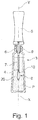
- FIG. 1 a packaging and application device comprising a container 3 containing a product P to be applied to the eyelashes and / or eyebrows and an applicator 1 for applying the said product P.
- the applicator 1 comprises an applicator member 8 according to the invention connected by a rod 7 to a gripping member 5 which is also a closure member of the container 3.
- This closure member 5 is, for example, as illustrated, a cover arranged to be screwed on a neck 9 of the container.
- the container 3 may comprise a wiper member 6 of the applicator 1, fixed in the neck 9 of the container 3.
- the applicator member 8 comprises a core 10 carrying application elements 20, in particular teeth according to the invention, as well as pins, if appropriate.
- the rod 7 may comprise, where appropriate, an annular necking on its portion which is positioned opposite the lip of the wiper member 6, so as not to mechanically stress it excessively during storage.
- the applicator member 8 can be connected in various ways to the rod 7 and comprises for example, as illustrated, a nozzle 4 arranged to be fixed in a housing thereof.
- Fixing the applicator member 8 on the rod 7 can be done by any means and particularly by force fitting, stapling, latching, gluing, welding or crimping, in the corresponding housing provided at the end of the rod 7 .
- the rod 7 may be inserted into a housing provided in the core 10, or the rod and the core may be formed at least partly in one piece.
- the core is of elongate shape along a longitudinal axis X, which may be rectilinear or curved, being preferably rectilinear.
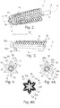
- the soul 10 can be, as illustrated on the figure 4 , over the majority of its length, of polygonal cross section, in particular hexagonal, the sides of the core 10 defining longitudinal faces 40.
- the latter may all be provided with application elements 20, including teeth.
- the faces 40 may be curved or, as in the example shown, planes. In a variant not shown, only a portion of the faces of the core 10 carries application elements 20.
- the core 10 can alternatively and as illustrated on the Figure 4B , be on the majority of its length, of circular cross section.
- the longitudinal axis X may be central and the core 10 may be inscribed in a cross section in a circle of diameter less than or equal to 5 mm.
- the cross section of the core 10 can expand in the direction of the tip 4.
- the cross section of the core 10 may thin towards the tip 4.
- the core 10 may be of constant cross section, in particular be of cylindrical shape.
- the core 10 may be hollow, the inner diameter of the core 10 being preferably between 1 mm and 2.5 mm.
- the core 10 may comprise, at its distal end, a head which is tapered toward the free end 42, in order to facilitate the retraction of the applicator 1 into the receptacle 3.
- the core 10 may consist of a relatively rigid thermoplastic material or not, for example SEBS, a silicone, latex, butyl, EPDM, a nitrile, a thermoplastic elastomer, a polyester elastomer, polyamide , polyethylene or vinyl, a polyolefin such as PE or PP, PVC, EVA, PS, PET, POM, PA or PMMA.
- materials known as Hytrel®, Cariflex®, Alixine®, Santoprene® , Pebax® can be used, this list not being limiting.
- the core 10 can be made in one piece by molding material with the rod 7.
- the core 10 can be twisted, the teeth 20 then following the spin performed by the soul.
- the applicator member 8 comprises teeth 20, which each extend from the core 10 towards the outside, in the direction of a free end 26.
- the latter can be, as illustrated on the figure 5 , a curved portion, especially a circle or parabola, and preferably an ellipse portion.
- the convex edge 22 may extend over more than half the height h of each of the teeth 20, better over the entire height h of each of the teeth 20, as illustrated in FIG. figure 5 .
- Each tooth 20 can thin, as illustrated on the figure 6 towards the convex edge 22 in particular, in cross section of the tooth 20, a vertex angle ⁇ .
- the angle ⁇ may be less than or equal to 40 °, more preferably less than or equal to 15 °. This Thinning allows a deviation of the eyelashes from their contact with the applicator 1.
- the convex edge 22 defines an edge.
- each tooth 20 thins in front view upwards on at least a portion B of its height, better at least half of its height.
- Part B may extend from the base 25.
- the large dimension of the base 25 is for example between 0.3 mm and 3 mm.
- each tooth is, in front view, as shown in FIG. figure 5 , tapered, forming in particular a point which facilitates the penetration into the eyelashes and the separation of the latter.
- each tooth 20 is preferably of flattened cross-section over part of its height, better over more than half of its height, even better over its entire height.
- the teeth 20 preferably have their flattening plane Z oriented perpendicular to the core 10.
- the flattening plane Z is in particular a median plane of symmetry for the tooth 20.
- each tooth 20 may comprise, in front view, a rectilinear edge 24, in particular radial with respect to the longitudinal axis X of the core 10, extending over more than half the height h of the tooth 20, preferably over the entire height h of the tooth 20.
- the tooth 20 is registered, in front view, in a rectangle of width substantially equal to the largest transverse dimension L of the tooth 20 in front view.
- each tooth 20 comprises, in front view, a concave edge 24 extending over more than half the height h of the tooth 20, preferably over the entire height h of the tooth 20.
- Each tooth 20 preferably comprises, as illustrated in particular at figure 6 , a flat face 24 which defines this rectilinear edge.
- the flat face 24 is opposite the convex edge 22 of the tooth 20.
- each tooth 20 tapers from the flat face 24 to the convex edge 22.
- Each tooth 20 may have two opposite longitudinal main faces 31 and 32 which are flat or curved, being concave or preferably, as shown in FIG. the figure 6 , convex outward. As illustrated on the figure 6 , the faces 31 and 32 are preferably ellipsoid portions.
- each tooth 20 has an angular extent ⁇ which is equal to the angular extent of the base of the tooth 25.
- the faces 31 and 32 are preferably, as illustrated in FIGS. Figures 6 to 6C , of the same shape. In the illustrated examples, the faces 31 and 32 connect the plane face 24 to the convex edge 22.
- the largest width L of each tooth 20 defined as the largest dimension of the tooth 20 in the plane of flattening Z may be between 0.3 mm and 2 mm, more preferably between 0.5 mm and 1.5 mm. This larger width L is preferably measured at the base of the teeth 20, as illustrated in FIG. figure 5 .
- each tooth 20 may be between 0.5 mm and 1 cm, better between 1 mm and 5 mm.
- the maximum thickness 1 of each tooth 20 may be between 0.2 mm and 2 mm, more preferably between 0.4 mm and 1.5 mm. This maximum thickness l can be measured at the base of the teeth 20.
- the thickness of each tooth 20 at its free end 26 may be less than or equal to 0.5 mm.
- the L / h ratio of the greatest width L of the tooth 20 over the height h of the tooth 20 may be between 0.5 and 2.
- the teeth 20 are full.
- the teeth 20 may have a through hole or not.
- Teeth 20 may extend from a single closed contour base.
- the circumferential extension ⁇ of the teeth 20 on the core may be less than or equal to 180 °, more preferably less than or equal to 90 °.
- teeth 20 are preferably made of the same material as at least a part of the core 10, better the entire core 10. Teeth 20 are preferably made in one piece with the core 10 by molding of thermoplastic material.
- the teeth 20 taper at their distal ends to form a tip.
- the tangents t 1 and t 2 of the surface of the tooth, taken in a front view at a height h equal to 90% of the height h of the tooth 20 form a lower ⁇ angle or equal to 90 °.
- each tooth 20 does not thin over its entire height.
- Each tooth 20 can then present, on a part A of its height, an area of constant width or increasing upwards.
- This part A has a height which is preferably less than half the height h of the tooth 20.
- the free end 26 forms a flat.
- the end 26 may be rounded.
- the faces 31 and 32 may be concave and are then for example portions of hyperboloid or paraboloid.
- the faces 31 and 32 can also be, as illustrated in the example of the Figure 6A , planes.
- the faces 31 and 32 can still be, as illustrated in FIG. Figure 6D , of different shapes.
- the plane of flattening Z is oriented obliquely with respect to the longitudinal axis X of the core 10 at an angle ⁇ between 45 ° and 90 °.
- each tooth 20 has a narrowed base.
- the large dimension b of the base 25 is then for example between 0.1 mm and 1.5 mm.
- the median axis of the plane face 24 does not extend perpendicular to the axis X but obliquely with respect thereto, towards the front, that is to say the end distal to the applicator, or to the back.
- each tooth 20 may comprise a relief 33 such as a recess, a recess and / or a notch on its surface.
- This relief 33 may be located on the convex edge 22 and / or on the opposite face 24 of the tooth 20 and / or on the core and / or on the other of the opposite main faces 31 and 32.
- Each tooth 20 may also be have an opening 35 therethrough, for example an axis opening perpendicular to the plane of flattening Z.
- the teeth 20 and the core 10 may be made of different materials, where appropriate, by bi-injection.
- the teeth 20 are for example molded through openings of the core 10.
- the teeth 20 may be made of a material softer than the core or, alternatively, harder than the core.
- the core 10 may have on its surface at least one pair of adjacent teeth, preferably at least one pair of adjacent teeth, even better, as shown in FIG. figure 2 a plurality of rows of adjacent pairs of teeth, such as the teeth 20 described above.
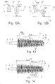
- the two teeth 20a and 20b of a pair may be of the same height, as illustrated in FIG. Figure 4A , or of different heights, as illustrated in particular in figure 4 . It can be seen in this last figure that the tooth 20a is slightly higher than the adjacent tooth 20b, which is in front of it, that is to say is closer to the distal end of the applicator.
- the convex edge 22 of the first tooth 20a can be oriented in front view to the right while the convex edge 22 of the second tooth 20b can be oriented to the left, or vice versa.
- This opposite orientation of the convex edges 22 allows the brush to be used in one direction as in the other, while producing the same effect.
- the teeth 20a and 20b are preferably axially offset by a distance D, the latter being the distance between the flattening planes Z of the two teeth 20a and 20b.
- the distance D can be between 0.5 mm and 3 mm, better between 0.5 mm and 1.5 mm.
- the teeth 20a and 20b are preferably offset about the longitudinal axis of the core ⁇ X.
- the angular difference between the two teeth 20a and 20b, defined, in front view, for the ⁇ angle between the radius of the core 10 passing through the middle X a of the arc of intersection of the first tooth 20a with the core 10 and the radius of the core 10 passing through the middle X b of the arc of intersection the second tooth 20b with the core 10 is preferably between 15 ° and 60 °.
- the teeth 20a and 20b can be superimposed at least partially on at least a part of the height h of the two teeth 20a and 20b, better as visible on the figure 11 , over the entire height of at least one of the teeth 20a or 20b.
- the angular distance ⁇ between the two teeth 20a and 20b is smaller than the angular extent ⁇ occupied by each of the teeth 20a and 20b, the latter being defined by the angle occupied by the tooth at its base.
- ⁇ the overlap angle as defined, in front view, the angle occupied by the Sab overlap surface between the two teeth 20a and 20b with respect to the longitudinal axis X, that is to say ⁇ - ⁇ , may be less than or equal to 30 °.
- the first tooth 20a can be, as illustrated in FIGS. Figures 4, 4B and 13 larger than the second tooth 20b, or vice versa.
- the height ratio m / n is preferably between 0.1 and 0.9, where m is the height of the small tooth and n is the height of the large tooth.
- the teeth 20a and 20b can be, as illustrated in FIGS. figures 11 and 4A of the same height, the first tooth 20a being preferably in front of the image of the second tooth 20b with respect to a plane of symmetry M parallel to the longitudinal axis X of the core 10.
- the applicator member 8 may comprise at least one row 50 of pairs of teeth 15, better a plurality of rows 50 of pairs of teeth 15, the pairs of teeth 15 having teeth 20a and 20b as described above.
- the rows 50 extend preferentially along the longitudinal axis X of the core 10.
- the applicator member 8 may comprise at least two rows 50 of pairs of teeth 15, better still at least four rows 50, and still more preferably at least six rows 50 arranged around the longitudinal axis X of the core 10.
- All the rows 50 of the applicator member 8 are preferably identical.
- the teeth of each of the rows 50 preferably have the same abscissa, along the longitudinal axis X, as the teeth of the same rank of the adjacent rows 50.
- the teeth of the same rank appear aligned when the applicator member is viewed from the side.
- the rows 50 preferably have between them a regular spacing around the longitudinal axis X of the core 10.
- the angular difference ⁇ between two consecutive rows 50, when moving around the longitudinal axis X of the web 10, is preferably constant, the angular difference ⁇ being defined in front view by the angle between the spokes of the soul 10 which pass through the centers of said rows.
- the angular difference ⁇ is preferably between 15 ° and 95 °, more preferably between 45 ° and 75 °, more preferably equal to 60 °.
- Such rows 50 may be described as "double rows" because of the presence of two distinct alignments 50a and 50b of respective teeth 20a and 20b.
- the axial distance q between two pairs of consecutive teeth of the row 50 is preferably constant and between 0.8 mm and 4 mm, the axial distance q being defined by the distance in side view between the flattening planes Z of the first teeth 20a within the alignment 50a of teeth 20a.
- the core is preferably of hexagonal section, as illustrated.
- the applicator member 8 preferably comprises six double rows 50, each double row 50 having its longitudinal axis disposed on an edge of the core 10.
- the teeth 20a extend over almost all of their base 25 on a planar faces 40 of the core 10, adjacent to said edge.
- the teeth 20b extend over almost all of their base 25 on the other flat face 40 adjacent to said edge.
- the envelope surface S of the teeth defined by the free end 26 of the teeth 20, may be a surface of revolution, in particular conical.
- the radius r S of the envelope surface S is preferably substantially increasing in the direction of the tip 4 over almost the entire length q max of the row 50.
- each alignment 50a and 50b has large teeth that alternate with small teeth, smaller in height than large teeth.
- the teeth of even rank of each alignment 50a and 50b are for example smaller than the teeth of odd rank, or vice versa.
- the ratio of the heights m / n is preferably between 0.1 and 0.9, where m is the height of the small tooth and n is the height of the large tooth.
- Each odd-numbered tooth of the first alignment 50a is preferably of the same height h as the even-ranking, adjacent tooth of the second alignment 50b.
- Each even rank tooth of the first alignment 50a is preferably of the same height h as the adjacent odd-rank tooth of the second alignment 50b.
- the teeth 20a and 20b are then of the same size by pair of adjacent teeth of the double row 50.
- the first alignment 50a is superimposed at 54, as shown in FIG. figure 4 with the second alignment 50b of an adjacent double row 50.
- This superposition can be only of small extent.
- the covering width defined as, in front view, the width at the base 25 of the overlap zone between the teeth, is for example less than or equal to 0.5 mm.
- the teeth of rows 50 neighbors are not superimposed.
- the angular difference ⁇ between two consecutive rows 50, when one moves around the longitudinal axis X of the applicator member 8, may also, in a variant, vary around the core 10.
- the pairs of teeth 15 may have, relative to each other, an increasing height when moving along the longitudinal axis of the core over almost the entire length q max of the row 50
- the height h of the teeth 20a and 20b of a row 50 preferably each of the rows 50 of teeth, may vary alternately over most of the length q max of the row 50.
- Each of the teeth of even rank 20b may be larger than the teeth of odd rank 20a immediately adjacent or vice versa.
- the ratio m / n between two adjacent teeth is preferably between 0.1 and 0.9, where m is the height of one of the small teeth and n is the height of one of the large adjacent teeth.
- each alignment 50a and 50b may be of increasing height h away from the distal end of the application, the teeth 20a of the first alignment 50a being smaller than the teeth 20b of the second alignment 50b of FIG. same rank, or vice versa.
- the distance D between two adjacent teeth 20a and 20b of a row 50 may be variable over at least half the length q max of the row 50.
- the rows 50 of the applicator member 8 may be different from each other.
- the shape of the teeth 20a and 20b of two adjacent rows 50 may vary substantially, in particular by the height h of the teeth 20a and 20b corresponding.
- the teeth of a row 50 may all be larger than the teeth of the same rank of one of the adjacent rows 50.
- the teeth 20a and 20b of the same rank of neighboring rows 50 are not aligned around the longitudinal axis X.
- the teeth 20a and 20b of the same rank of neighboring rows 50 may be offset along the longitudinal axis X.
- the invention is not limited to the case of double rows.
- the rows may be simple and have a single alignment of teeth as previously described or pairs of aligned teeth 20a and 20b.
- the applicator member may comprise pins that can be placed between the teeth, more preferably rows of pins that can be placed between the rows of teeth.
- the applicator member may be vibrating, that is to say that it may be applied vibration during application, combing or removal of the product.
- the applicator member may be rotatable, that is to say it may be rotated about the longitudinal axis of the core, for example during application, combing eyelashes or taking the product.
- the application member is heated, that is to say it may comprise a heating element for heating the eyelashes or eyebrows, and / or the teeth and / or the soul of the implementing body.
- the applicator member may also be vibrating and / or rotating and / or heating.
- the teeth can be flocked and thus have a roughness or can receive a chemical or mechanical treatment promoting the sliding of the eyelashes or eyebrows.
Landscapes
- Brushes (AREA)
- Physics & Mathematics (AREA)
- Geometry (AREA)
- Cosmetics (AREA)
Applications Claiming Priority (2)
| Application Number | Priority Date | Filing Date | Title |
|---|---|---|---|
| FR1355191A FR3006566B1 (fr) | 2013-06-06 | 2013-06-06 | Applicateur pour appliquer un produit sur les cils et/ou les sourcils |
| PCT/IB2014/062009 WO2014195914A1 (fr) | 2013-06-06 | 2014-06-06 | Applicateur pour appliquer un produit sur les cils et/ou sourcils |
Publications (2)
| Publication Number | Publication Date |
|---|---|
| EP3003092A1 EP3003092A1 (fr) | 2016-04-13 |
| EP3003092B1 true EP3003092B1 (fr) | 2018-07-18 |
Family
ID=49111394
Family Applications (1)
| Application Number | Title | Priority Date | Filing Date |
|---|---|---|---|
| EP14731820.8A Active EP3003092B1 (fr) | 2013-06-06 | 2014-06-06 | Applicateur pour appliquer un produit sur les cils et/ou sourcils |
Country Status (8)
Families Citing this family (14)
| Publication number | Priority date | Publication date | Assignee | Title |
|---|---|---|---|---|
| FR3032869B1 (fr) * | 2015-02-25 | 2018-05-11 | Societe Industrielle De Matieres Plastiques | Dispositif applicateur d'un produit de type fluide ou pateux sur des fibres keratiniques. |
| FR3034969B1 (fr) * | 2015-04-14 | 2018-09-07 | Societe Industrielle De Matieres Plastiques | Dispositif applicateur d'un produit de type fluide ou pateux sur des fibres keratiniques |
| FR3035779B1 (fr) | 2015-05-06 | 2017-09-01 | Oreal | Applicateur pour l'application d'un produit cosmetique |
| FR3039382B1 (fr) | 2015-07-31 | 2017-08-11 | Montaigu Dev | Dispositif applicateur d'un produit fluide ou pateux sur des fibres keratiniques. |
| CN109475224A (zh) * | 2016-06-08 | 2019-03-15 | 马蒂埃尔斯塑胶工业公司 | 用于在角蛋白纤维上敷抹流体或糊状产品的涂敷器装置 |
| FR3070839B1 (fr) * | 2017-09-12 | 2025-04-11 | Oreal | Applicateur cosmetique |
| FR3070840B1 (fr) * | 2017-09-12 | 2021-11-12 | Oreal | Applicateur cosmetique |
| FR3070841B1 (fr) | 2017-09-12 | 2021-07-16 | Oreal | Applicateur cosmetique |
| FR3070842B1 (fr) * | 2017-09-12 | 2021-07-16 | Oreal | Applicateur cosmetique |
| FR3090299B1 (fr) | 2018-12-19 | 2021-04-30 | Oreal | Applicateur comportant un organe d’application fabriqué par synthèse additive |
| FR3090297B1 (fr) | 2018-12-19 | 2021-10-15 | Oreal | Applicateur cosmétique en spirale |
| FR3090301B1 (fr) | 2018-12-19 | 2021-05-14 | Oreal | Applicateur comportant un organe d’application à branche ouverte |
| FR3110060B1 (fr) * | 2020-05-18 | 2023-09-08 | Oreal | Applicateur pour appliquer un produit sur les cils et/ou sourcils |
| CN117580488A (zh) * | 2021-06-29 | 2024-02-20 | 马蒂埃尔斯塑胶工业公司 | 用于将流体或糊状类型产品涂抹到角质纤维上的涂抹器装置 |
Citations (2)
| Publication number | Priority date | Publication date | Assignee | Title |
|---|---|---|---|---|
| US6412496B1 (en) * | 1999-07-21 | 2002-07-02 | L'oreal S.A. | Eyelash product applicator, applicator system and method |
| US6581610B1 (en) * | 1999-07-21 | 2003-06-24 | L'oreal S.A. | Applicator, applicator system, and method for applying a product to the eyelashes |
Family Cites Families (12)
| Publication number | Priority date | Publication date | Assignee | Title |
|---|---|---|---|---|
| FR2690318A1 (fr) * | 1992-04-27 | 1993-10-29 | Oreal | Brosse destinée à l'application d'un produit cosmétique, en particulier sur les cils ou les cheveux, et procédé de fabrication d'une telle brosse. |
| FR2796527B1 (fr) * | 1999-07-21 | 2001-09-28 | Oreal | Dispositif de conditionnement et d'application d'un produit sur les cils ou les sourcils |
| FR2837077B1 (fr) | 2002-03-13 | 2004-12-17 | Oreal | Dispositif pour peigner les cils et/ou les sourcils et/ou appliquer un produit sur ceux-ci |
| FR2872394B1 (fr) * | 2004-07-01 | 2007-04-20 | Oreal | Dispositif pour l'application d'un produit sur les fibres keratiniques |
| JP4783079B2 (ja) * | 2005-07-08 | 2011-09-28 | 株式会社新和製作所 | 化粧用塗布具及び化粧用塗布具成形用金型 |
| FR2902984B1 (fr) * | 2006-06-28 | 2009-03-20 | Oreal | Dispositif pour l'application d'un produit sur les cils ou les sourcils. |
| FR2922422B1 (fr) | 2007-10-23 | 2009-12-18 | Oreal | Applicateur pour peigner ou appliquer un produit sur les cils |
| FR2934478B1 (fr) | 2008-08-01 | 2011-08-26 | Oreal | Applicateur pour peigner et/ou appliquer un produit sur les cils et/ou les sourcils |
| FR2937514B1 (fr) * | 2008-10-29 | 2012-12-07 | Ile M V R Soc Civ | Dispositif applicateur d'un produit cosmetique fluide ou pateux, typiquement du mascara |
| FR2951359B1 (fr) * | 2009-10-15 | 2019-12-27 | L'oreal | Dispositif pour appliquer un produit sur les cils ou les sourcils. |
| FR2961384B1 (fr) | 2010-06-21 | 2019-08-09 | L'oreal | Applicateur d'un produit cosmetique, de maquillage ou de soin, sur les cils ou les sourcils |
| FR2962888B1 (fr) | 2010-07-20 | 2012-08-31 | Oreal | Applicateur et dispositif de conditionnement et d'application comportant un tel applicateur. |
-
2013
- 2013-06-06 FR FR1355191A patent/FR3006566B1/fr active Active
-
2014
- 2014-06-06 EP EP14731820.8A patent/EP3003092B1/fr active Active
- 2014-06-06 US US14/896,615 patent/US10299565B2/en active Active
- 2014-06-06 WO PCT/IB2014/062009 patent/WO2014195914A1/fr active Application Filing
- 2014-06-06 CN CN201480044097.4A patent/CN105473024B/zh active Active
- 2014-06-06 ES ES14731820.8T patent/ES2689929T3/es active Active
- 2014-06-06 JP JP2016517728A patent/JP6894234B2/ja active Active
- 2014-06-06 KR KR1020167000077A patent/KR102306530B1/ko active Active
-
2019
- 2019-12-05 JP JP2019220657A patent/JP2020039930A/ja active Pending
Patent Citations (2)
| Publication number | Priority date | Publication date | Assignee | Title |
|---|---|---|---|---|
| US6412496B1 (en) * | 1999-07-21 | 2002-07-02 | L'oreal S.A. | Eyelash product applicator, applicator system and method |
| US6581610B1 (en) * | 1999-07-21 | 2003-06-24 | L'oreal S.A. | Applicator, applicator system, and method for applying a product to the eyelashes |
Also Published As
| Publication number | Publication date |
|---|---|
| US20160135568A1 (en) | 2016-05-19 |
| KR20160015362A (ko) | 2016-02-12 |
| JP6894234B2 (ja) | 2021-06-30 |
| CN105473024A (zh) | 2016-04-06 |
| JP2016521603A (ja) | 2016-07-25 |
| JP2020039930A (ja) | 2020-03-19 |
| EP3003092A1 (fr) | 2016-04-13 |
| ES2689929T3 (es) | 2018-11-16 |
| FR3006566B1 (fr) | 2018-04-27 |
| US10299565B2 (en) | 2019-05-28 |
| FR3006566A1 (fr) | 2014-12-12 |
| WO2014195914A1 (fr) | 2014-12-11 |
| KR102306530B1 (ko) | 2021-09-28 |
| CN105473024B (zh) | 2017-11-28 |
Similar Documents
| Publication | Publication Date | Title |
|---|---|---|
| EP3003092B1 (fr) | Applicateur pour appliquer un produit sur les cils et/ou sourcils | |
| EP3003091B1 (fr) | Applicateur pour appliquer un produit sur les cils et/ou les sourcils | |
| EP1872682B1 (fr) | Dispositif pour l'application d'un produit sur les cils ou les sourcils | |
| EP1070468B1 (fr) | Dispositif pour l'application d'un produit sur les cils ou les sourcils | |
| EP1070465B1 (fr) | Dispositif de conditionnement et d'application d'un produit sur les cils ou les sourcils | |
| FR3004905A1 (fr) | Applicateur pour appliquer un produit sur les cils et/ou les sourcils | |
| FR2922422A1 (fr) | Applicateur pour peigner ou appliquer un produit sur les cils | |
| FR2983690A1 (fr) | Applicateur pour peigner ou appliquer un produit sur les cils et/ou les sourcils | |
| FR2961384B1 (fr) | Applicateur d'un produit cosmetique, de maquillage ou de soin, sur les cils ou les sourcils | |
| FR2951359A1 (fr) | Dispositif pour appliquer un produit sur les cils ou les sourcils. | |
| FR3035779A1 (fr) | Applicateur pour l'application d'un produit cosmetique | |
| FR2922420A1 (fr) | Applicateur pour l'application d'un produit sur les cils ou les sourcils | |
| FR2922421A1 (fr) | Applicateur pour peigner ou appliquer un produit sur les cils ou les sourcils | |
| EP1342428A1 (fr) | Dispositif pour peigner et/ou brosser les cils et/ou les sourcils et/ou appliquer un produit sur ceux-ci | |
| FR3066367B1 (fr) | Applicateur pour appliquer un produit sur les cils | |
| EP3013175B1 (fr) | Dispositif d'application d'un produit cosmetique | |
| FR2939618A1 (fr) | Applicateur pour appliquer un produit cosmetique, de maquillage ou de soin, sur les matieres keratiniques | |
| FR3014656A1 (fr) | Applicateur d'un produit cosmetique, de maquillage ou de soin, sur les cils et/ou les sourcils | |
| FR3004906A1 (fr) | Dispositif d'application d'un produit cosmetique. | |
| FR3026283A1 (fr) | Applicateur d'un produit cosmetique, de maquillage ou de soin, sur les cils et/ou les sourcils | |
| FR3030204A1 (fr) | Applicateur d'un produit cosmetique, de maquillage ou de soin, sur les cils et/ou les sourcils | |
| FR3013951A1 (fr) | Applicateur d'un produit cosmetique, de maquillage ou de soin, sur les cils ou les sourcils | |
| FR3070842A1 (fr) | Applicateur cosmetique | |
| FR2989254A1 (fr) | Applicateur pour l'application d'un produit cosmetique sur les cils et/ou les sourcils | |
| FR3045295A1 (fr) | Applicateur d'un produit cosmetique, de maquillage ou de soin, sur les cils et/ou les sourcils |
Legal Events
| Date | Code | Title | Description |
|---|---|---|---|
| PUAI | Public reference made under article 153(3) epc to a published international application that has entered the european phase |
Free format text: ORIGINAL CODE: 0009012 |
|
| 17P | Request for examination filed |
Effective date: 20151207 |
|
| AK | Designated contracting states |
Kind code of ref document: A1 Designated state(s): AL AT BE BG CH CY CZ DE DK EE ES FI FR GB GR HR HU IE IS IT LI LT LU LV MC MK MT NL NO PL PT RO RS SE SI SK SM TR |
|
| AX | Request for extension of the european patent |
Extension state: BA ME |
|
| RIN1 | Information on inventor provided before grant (corrected) |
Inventor name: ANNONAY, WENDY Inventor name: SANCHEZ, MARCEL Inventor name: CAULIER, ERIC |
|
| TPAC | Observations filed by third parties |
Free format text: ORIGINAL CODE: EPIDOSNTIPA |
|
| DAX | Request for extension of the european patent (deleted) | ||
| TPAC | Observations filed by third parties |
Free format text: ORIGINAL CODE: EPIDOSNTIPA |
|
| STAA | Information on the status of an ep patent application or granted ep patent |
Free format text: STATUS: EXAMINATION IS IN PROGRESS |
|
| 17Q | First examination report despatched |
Effective date: 20170207 |
|
| GRAP | Despatch of communication of intention to grant a patent |
Free format text: ORIGINAL CODE: EPIDOSNIGR1 |
|
| STAA | Information on the status of an ep patent application or granted ep patent |
Free format text: STATUS: GRANT OF PATENT IS INTENDED |
|
| INTG | Intention to grant announced |
Effective date: 20180122 |
|
| GRAS | Grant fee paid |
Free format text: ORIGINAL CODE: EPIDOSNIGR3 |
|
| GRAA | (expected) grant |
Free format text: ORIGINAL CODE: 0009210 |
|
| STAA | Information on the status of an ep patent application or granted ep patent |
Free format text: STATUS: THE PATENT HAS BEEN GRANTED |
|
| AK | Designated contracting states |
Kind code of ref document: B1 Designated state(s): AL AT BE BG CH CY CZ DE DK EE ES FI FR GB GR HR HU IE IS IT LI LT LU LV MC MK MT NL NO PL PT RO RS SE SI SK SM TR |
|
| REG | Reference to a national code |
Ref country code: GB Ref legal event code: FG4D Free format text: NOT ENGLISH |
|
| REG | Reference to a national code |
Ref country code: CH Ref legal event code: EP |
|
| REG | Reference to a national code |
Ref country code: IE Ref legal event code: FG4D Free format text: LANGUAGE OF EP DOCUMENT: FRENCH |
|
| REG | Reference to a national code |
Ref country code: AT Ref legal event code: REF Ref document number: 1018431 Country of ref document: AT Kind code of ref document: T Effective date: 20180815 |
|
| REG | Reference to a national code |
Ref country code: DE Ref legal event code: R096 Ref document number: 602014028694 Country of ref document: DE |
|
| REG | Reference to a national code |
Ref country code: ES Ref legal event code: FG2A Ref document number: 2689929 Country of ref document: ES Kind code of ref document: T3 Effective date: 20181116 |
|
| REG | Reference to a national code |
Ref country code: NL Ref legal event code: MP Effective date: 20180718 |
|
| REG | Reference to a national code |
Ref country code: LT Ref legal event code: MG4D |
|
| REG | Reference to a national code |
Ref country code: AT Ref legal event code: MK05 Ref document number: 1018431 Country of ref document: AT Kind code of ref document: T Effective date: 20180718 |
|
| PG25 | Lapsed in a contracting state [announced via postgrant information from national office to epo] |
Ref country code: NL Free format text: LAPSE BECAUSE OF FAILURE TO SUBMIT A TRANSLATION OF THE DESCRIPTION OR TO PAY THE FEE WITHIN THE PRESCRIBED TIME-LIMIT Effective date: 20180718 |
|
| PG25 | Lapsed in a contracting state [announced via postgrant information from national office to epo] |
Ref country code: GR Free format text: LAPSE BECAUSE OF FAILURE TO SUBMIT A TRANSLATION OF THE DESCRIPTION OR TO PAY THE FEE WITHIN THE PRESCRIBED TIME-LIMIT Effective date: 20181019 Ref country code: FI Free format text: LAPSE BECAUSE OF FAILURE TO SUBMIT A TRANSLATION OF THE DESCRIPTION OR TO PAY THE FEE WITHIN THE PRESCRIBED TIME-LIMIT Effective date: 20180718 Ref country code: SE Free format text: LAPSE BECAUSE OF FAILURE TO SUBMIT A TRANSLATION OF THE DESCRIPTION OR TO PAY THE FEE WITHIN THE PRESCRIBED TIME-LIMIT Effective date: 20180718 Ref country code: LT Free format text: LAPSE BECAUSE OF FAILURE TO SUBMIT A TRANSLATION OF THE DESCRIPTION OR TO PAY THE FEE WITHIN THE PRESCRIBED TIME-LIMIT Effective date: 20180718 Ref country code: PL Free format text: LAPSE BECAUSE OF FAILURE TO SUBMIT A TRANSLATION OF THE DESCRIPTION OR TO PAY THE FEE WITHIN THE PRESCRIBED TIME-LIMIT Effective date: 20180718 Ref country code: IS Free format text: LAPSE BECAUSE OF FAILURE TO SUBMIT A TRANSLATION OF THE DESCRIPTION OR TO PAY THE FEE WITHIN THE PRESCRIBED TIME-LIMIT Effective date: 20181118 Ref country code: RS Free format text: LAPSE BECAUSE OF FAILURE TO SUBMIT A TRANSLATION OF THE DESCRIPTION OR TO PAY THE FEE WITHIN THE PRESCRIBED TIME-LIMIT Effective date: 20180718 Ref country code: NO Free format text: LAPSE BECAUSE OF FAILURE TO SUBMIT A TRANSLATION OF THE DESCRIPTION OR TO PAY THE FEE WITHIN THE PRESCRIBED TIME-LIMIT Effective date: 20181018 Ref country code: BG Free format text: LAPSE BECAUSE OF FAILURE TO SUBMIT A TRANSLATION OF THE DESCRIPTION OR TO PAY THE FEE WITHIN THE PRESCRIBED TIME-LIMIT Effective date: 20181018 Ref country code: AT Free format text: LAPSE BECAUSE OF FAILURE TO SUBMIT A TRANSLATION OF THE DESCRIPTION OR TO PAY THE FEE WITHIN THE PRESCRIBED TIME-LIMIT Effective date: 20180718 |
|
| PG25 | Lapsed in a contracting state [announced via postgrant information from national office to epo] |
Ref country code: AL Free format text: LAPSE BECAUSE OF FAILURE TO SUBMIT A TRANSLATION OF THE DESCRIPTION OR TO PAY THE FEE WITHIN THE PRESCRIBED TIME-LIMIT Effective date: 20180718 Ref country code: HR Free format text: LAPSE BECAUSE OF FAILURE TO SUBMIT A TRANSLATION OF THE DESCRIPTION OR TO PAY THE FEE WITHIN THE PRESCRIBED TIME-LIMIT Effective date: 20180718 Ref country code: LV Free format text: LAPSE BECAUSE OF FAILURE TO SUBMIT A TRANSLATION OF THE DESCRIPTION OR TO PAY THE FEE WITHIN THE PRESCRIBED TIME-LIMIT Effective date: 20180718 |
|
| REG | Reference to a national code |
Ref country code: DE Ref legal event code: R097 Ref document number: 602014028694 Country of ref document: DE |
|
| PG25 | Lapsed in a contracting state [announced via postgrant information from national office to epo] |
Ref country code: EE Free format text: LAPSE BECAUSE OF FAILURE TO SUBMIT A TRANSLATION OF THE DESCRIPTION OR TO PAY THE FEE WITHIN THE PRESCRIBED TIME-LIMIT Effective date: 20180718 Ref country code: RO Free format text: LAPSE BECAUSE OF FAILURE TO SUBMIT A TRANSLATION OF THE DESCRIPTION OR TO PAY THE FEE WITHIN THE PRESCRIBED TIME-LIMIT Effective date: 20180718 Ref country code: CZ Free format text: LAPSE BECAUSE OF FAILURE TO SUBMIT A TRANSLATION OF THE DESCRIPTION OR TO PAY THE FEE WITHIN THE PRESCRIBED TIME-LIMIT Effective date: 20180718 |
|
| PLBE | No opposition filed within time limit |
Free format text: ORIGINAL CODE: 0009261 |
|
| STAA | Information on the status of an ep patent application or granted ep patent |
Free format text: STATUS: NO OPPOSITION FILED WITHIN TIME LIMIT |
|
| PG25 | Lapsed in a contracting state [announced via postgrant information from national office to epo] |
Ref country code: SM Free format text: LAPSE BECAUSE OF FAILURE TO SUBMIT A TRANSLATION OF THE DESCRIPTION OR TO PAY THE FEE WITHIN THE PRESCRIBED TIME-LIMIT Effective date: 20180718 Ref country code: DK Free format text: LAPSE BECAUSE OF FAILURE TO SUBMIT A TRANSLATION OF THE DESCRIPTION OR TO PAY THE FEE WITHIN THE PRESCRIBED TIME-LIMIT Effective date: 20180718 Ref country code: SK Free format text: LAPSE BECAUSE OF FAILURE TO SUBMIT A TRANSLATION OF THE DESCRIPTION OR TO PAY THE FEE WITHIN THE PRESCRIBED TIME-LIMIT Effective date: 20180718 |
|
| 26N | No opposition filed |
Effective date: 20190423 |
|
| PG25 | Lapsed in a contracting state [announced via postgrant information from national office to epo] |
Ref country code: SI Free format text: LAPSE BECAUSE OF FAILURE TO SUBMIT A TRANSLATION OF THE DESCRIPTION OR TO PAY THE FEE WITHIN THE PRESCRIBED TIME-LIMIT Effective date: 20180718 |
|
| PG25 | Lapsed in a contracting state [announced via postgrant information from national office to epo] |
Ref country code: MC Free format text: LAPSE BECAUSE OF FAILURE TO SUBMIT A TRANSLATION OF THE DESCRIPTION OR TO PAY THE FEE WITHIN THE PRESCRIBED TIME-LIMIT Effective date: 20180718 |
|
| REG | Reference to a national code |
Ref country code: CH Ref legal event code: PL |
|
| REG | Reference to a national code |
Ref country code: BE Ref legal event code: MM Effective date: 20190630 |
|
| PG25 | Lapsed in a contracting state [announced via postgrant information from national office to epo] |
Ref country code: TR Free format text: LAPSE BECAUSE OF FAILURE TO SUBMIT A TRANSLATION OF THE DESCRIPTION OR TO PAY THE FEE WITHIN THE PRESCRIBED TIME-LIMIT Effective date: 20180718 |
|
| PG25 | Lapsed in a contracting state [announced via postgrant information from national office to epo] |
Ref country code: IE Free format text: LAPSE BECAUSE OF NON-PAYMENT OF DUE FEES Effective date: 20190606 |
|
| PG25 | Lapsed in a contracting state [announced via postgrant information from national office to epo] |
Ref country code: LU Free format text: LAPSE BECAUSE OF NON-PAYMENT OF DUE FEES Effective date: 20190606 Ref country code: CH Free format text: LAPSE BECAUSE OF NON-PAYMENT OF DUE FEES Effective date: 20190630 Ref country code: LI Free format text: LAPSE BECAUSE OF NON-PAYMENT OF DUE FEES Effective date: 20190630 Ref country code: BE Free format text: LAPSE BECAUSE OF NON-PAYMENT OF DUE FEES Effective date: 20190630 |
|
| PG25 | Lapsed in a contracting state [announced via postgrant information from national office to epo] |
Ref country code: PT Free format text: LAPSE BECAUSE OF FAILURE TO SUBMIT A TRANSLATION OF THE DESCRIPTION OR TO PAY THE FEE WITHIN THE PRESCRIBED TIME-LIMIT Effective date: 20181118 |
|
| PG25 | Lapsed in a contracting state [announced via postgrant information from national office to epo] |
Ref country code: CY Free format text: LAPSE BECAUSE OF FAILURE TO SUBMIT A TRANSLATION OF THE DESCRIPTION OR TO PAY THE FEE WITHIN THE PRESCRIBED TIME-LIMIT Effective date: 20180718 |
|
| PG25 | Lapsed in a contracting state [announced via postgrant information from national office to epo] |
Ref country code: MT Free format text: LAPSE BECAUSE OF FAILURE TO SUBMIT A TRANSLATION OF THE DESCRIPTION OR TO PAY THE FEE WITHIN THE PRESCRIBED TIME-LIMIT Effective date: 20180718 Ref country code: HU Free format text: LAPSE BECAUSE OF FAILURE TO SUBMIT A TRANSLATION OF THE DESCRIPTION OR TO PAY THE FEE WITHIN THE PRESCRIBED TIME-LIMIT; INVALID AB INITIO Effective date: 20140606 |
|
| PG25 | Lapsed in a contracting state [announced via postgrant information from national office to epo] |
Ref country code: MK Free format text: LAPSE BECAUSE OF FAILURE TO SUBMIT A TRANSLATION OF THE DESCRIPTION OR TO PAY THE FEE WITHIN THE PRESCRIBED TIME-LIMIT Effective date: 20180718 |
|
| REG | Reference to a national code |
Ref country code: FR Ref legal event code: PLFP Year of fee payment: 10 |
|
| PGFP | Annual fee paid to national office [announced via postgrant information from national office to epo] |
Ref country code: ES Payment date: 20240704 Year of fee payment: 11 |
|
| PGFP | Annual fee paid to national office [announced via postgrant information from national office to epo] |
Ref country code: DE Payment date: 20250402 Year of fee payment: 12 |
|
| PGFP | Annual fee paid to national office [announced via postgrant information from national office to epo] |
Ref country code: GB Payment date: 20250401 Year of fee payment: 12 |
|
| PGFP | Annual fee paid to national office [announced via postgrant information from national office to epo] |
Ref country code: IT Payment date: 20250522 Year of fee payment: 12 |
|
| PGFP | Annual fee paid to national office [announced via postgrant information from national office to epo] |
Ref country code: FR Payment date: 20250401 Year of fee payment: 12 |