EP3002537A1 - Radiator and refrigerating cycle device - Google Patents
Radiator and refrigerating cycle device Download PDFInfo
- Publication number
- EP3002537A1 EP3002537A1 EP15186759.5A EP15186759A EP3002537A1 EP 3002537 A1 EP3002537 A1 EP 3002537A1 EP 15186759 A EP15186759 A EP 15186759A EP 3002537 A1 EP3002537 A1 EP 3002537A1
- Authority
- EP
- European Patent Office
- Prior art keywords
- heat transfer
- refrigerant
- transfer tube
- outlet
- inlet
- Prior art date
- Legal status (The legal status is an assumption and is not a legal conclusion. Google has not performed a legal analysis and makes no representation as to the accuracy of the status listed.)
- Granted
Links
Images



Classifications
-
- F—MECHANICAL ENGINEERING; LIGHTING; HEATING; WEAPONS; BLASTING
- F28—HEAT EXCHANGE IN GENERAL
- F28D—HEAT-EXCHANGE APPARATUS, NOT PROVIDED FOR IN ANOTHER SUBCLASS, IN WHICH THE HEAT-EXCHANGE MEDIA DO NOT COME INTO DIRECT CONTACT
- F28D1/00—Heat-exchange apparatus having stationary conduit assemblies for one heat-exchange medium only, the media being in contact with different sides of the conduit wall, in which the other heat-exchange medium is a large body of fluid, e.g. domestic or motor car radiators
- F28D1/02—Heat-exchange apparatus having stationary conduit assemblies for one heat-exchange medium only, the media being in contact with different sides of the conduit wall, in which the other heat-exchange medium is a large body of fluid, e.g. domestic or motor car radiators with heat-exchange conduits immersed in the body of fluid
- F28D1/04—Heat-exchange apparatus having stationary conduit assemblies for one heat-exchange medium only, the media being in contact with different sides of the conduit wall, in which the other heat-exchange medium is a large body of fluid, e.g. domestic or motor car radiators with heat-exchange conduits immersed in the body of fluid with tubular conduits
- F28D1/047—Heat-exchange apparatus having stationary conduit assemblies for one heat-exchange medium only, the media being in contact with different sides of the conduit wall, in which the other heat-exchange medium is a large body of fluid, e.g. domestic or motor car radiators with heat-exchange conduits immersed in the body of fluid with tubular conduits the conduits being bent, e.g. in a serpentine or zig-zag
- F28D1/0475—Heat-exchange apparatus having stationary conduit assemblies for one heat-exchange medium only, the media being in contact with different sides of the conduit wall, in which the other heat-exchange medium is a large body of fluid, e.g. domestic or motor car radiators with heat-exchange conduits immersed in the body of fluid with tubular conduits the conduits being bent, e.g. in a serpentine or zig-zag the conduits having a single U-bend
-
- F—MECHANICAL ENGINEERING; LIGHTING; HEATING; WEAPONS; BLASTING
- F25—REFRIGERATION OR COOLING; COMBINED HEATING AND REFRIGERATION SYSTEMS; HEAT PUMP SYSTEMS; MANUFACTURE OR STORAGE OF ICE; LIQUEFACTION SOLIDIFICATION OF GASES
- F25B—REFRIGERATION MACHINES, PLANTS OR SYSTEMS; COMBINED HEATING AND REFRIGERATION SYSTEMS; HEAT PUMP SYSTEMS
- F25B39/00—Evaporators; Condensers
- F25B39/04—Condensers
-
- F—MECHANICAL ENGINEERING; LIGHTING; HEATING; WEAPONS; BLASTING
- F28—HEAT EXCHANGE IN GENERAL
- F28F—DETAILS OF HEAT-EXCHANGE AND HEAT-TRANSFER APPARATUS, OF GENERAL APPLICATION
- F28F1/00—Tubular elements; Assemblies of tubular elements
- F28F1/10—Tubular elements and assemblies thereof with means for increasing heat-transfer area, e.g. with fins, with projections, with recesses
- F28F1/12—Tubular elements and assemblies thereof with means for increasing heat-transfer area, e.g. with fins, with projections, with recesses the means being only outside the tubular element
- F28F1/24—Tubular elements and assemblies thereof with means for increasing heat-transfer area, e.g. with fins, with projections, with recesses the means being only outside the tubular element and extending transversely
- F28F1/32—Tubular elements and assemblies thereof with means for increasing heat-transfer area, e.g. with fins, with projections, with recesses the means being only outside the tubular element and extending transversely the means having portions engaging further tubular elements
-
- F—MECHANICAL ENGINEERING; LIGHTING; HEATING; WEAPONS; BLASTING
- F25—REFRIGERATION OR COOLING; COMBINED HEATING AND REFRIGERATION SYSTEMS; HEAT PUMP SYSTEMS; MANUFACTURE OR STORAGE OF ICE; LIQUEFACTION SOLIDIFICATION OF GASES
- F25B—REFRIGERATION MACHINES, PLANTS OR SYSTEMS; COMBINED HEATING AND REFRIGERATION SYSTEMS; HEAT PUMP SYSTEMS
- F25B2309/00—Gas cycle refrigeration machines
- F25B2309/06—Compression machines, plants or systems characterised by the refrigerant being carbon dioxide
- F25B2309/061—Compression machines, plants or systems characterised by the refrigerant being carbon dioxide with cycle highest pressure above the supercritical pressure
-
- F—MECHANICAL ENGINEERING; LIGHTING; HEATING; WEAPONS; BLASTING
- F25—REFRIGERATION OR COOLING; COMBINED HEATING AND REFRIGERATION SYSTEMS; HEAT PUMP SYSTEMS; MANUFACTURE OR STORAGE OF ICE; LIQUEFACTION SOLIDIFICATION OF GASES
- F25B—REFRIGERATION MACHINES, PLANTS OR SYSTEMS; COMBINED HEATING AND REFRIGERATION SYSTEMS; HEAT PUMP SYSTEMS
- F25B9/00—Compression machines, plants or systems, in which the refrigerant is air or other gas of low boiling point
- F25B9/002—Compression machines, plants or systems, in which the refrigerant is air or other gas of low boiling point characterised by the refrigerant
- F25B9/008—Compression machines, plants or systems, in which the refrigerant is air or other gas of low boiling point characterised by the refrigerant the refrigerant being carbon dioxide
Definitions
- the present invention relates to a radiator which cools refrigerant boosted up to supercritical pressure by radiating heat thereof, and a refrigerating cycle device including the radiator.
- a known refrigerating cycle device including a compressor which boosts refrigerant up to supercritical pressure by using CO 2 (carbon dioxide) as the refrigerant, and a radiator which cools the refrigerant discharged from the compressor by radiating heat thereof (refer to Patent Literature 1, for example).
- a fin-and-tube heat exchanger is used as a radiator so as to improve efficiency in heat exchange.
- the fin-and-tube heat exchanger includes a plurality fin plates arranged at a predetermined interval, and a plurality of heat transfer tubes which is inserted into the fin plates and allows the refrigerant to flow inside thereof.
- a plurality of refrigerant channels formed in parallel is provided to improve cooling (heating) performance (refer to Patent Literature 2).
- a refrigerant outlet temperature is preferably lower in each of refrigerant channels of the radiator.
- an outlet heat transfer tube of a refrigerant channel is disposed adjacent to an inlet heat transfer tube of own or other refrigerant channel. Therefore, there is a risk that the refrigerant outlet temperature may be increased by high-temperature refrigerant flowing in the inlet heat transfer tube.
- the present invention is made in view of the above-described situation, and is directed to providing a radiator and a refrigerating cycle device, in which increase of a refrigerant outlet temperature at a refrigerant channel is suppressed.
- a radiator which radiates heat of refrigerant boosted up to supercritical pressure, comprises: a plurality of fin plates extending in a vertical direction and arranged at a predetermined interval; and a plurality of refrigerant channels formed in parallel by a heat transfer tube bundle inserted into the fin plates in multiple stages.
- Each of the plurality of refrigerant channels includes an inlet heat transfer tube disposed at an upper portion of the fin plates, an outlet heat transfer tube disposed at a lower portion of the fin plates, and an intermediate heat transfer tube disposed between the inlet heat transfer tube and the outlet heat transfer tube.
- each of the plurality of refrigerant channels includes the inlet heat transfer tube on upper portion side of the fin plates and also includes the outlet heat transfer tube on the lower portion side of the fin plates. Therefore, the outlet heat transfer tube of a refrigerant channel can be disposed apart from the inlet heat transfer tube of own or other refrigerant channel. Further, since the intermediate heat transfer tube is disposed between the inlet heat transfer tube and the outlet heat transfer tube, the inlet heat transfer tube is prevented from being disposed adjacent to the outlet heat transfer tube. Therefore, the refrigerant outlet temperature is suppressed from being increased by high-temperature refrigerant flowing in the inlet heat transfer tube, thereby achieving to improve a coefficient of performance in the refrigerating cycle.
- the refrigerant flows from an upper-stage heat transfer tube to a lower-stage heat transfer tube in each of the refrigerant channels.
- the refrigerant boosted up to the supercritical pressures is not condensed at the time of passing the radiator, but density (specific gravity) of the refrigerant gas is increased due to cooling. Therefore, circulation of the refrigerant is accelerated by the gravity by configuring the refrigerant channel such that the refrigerant flows from an upper-stage heat transfer tube to a lower-stage heat transfer tube. As a result, heat exchange efficiency can be improved.
- the radiator further includes a plurality of heat exchange units, the radiator being vertically divided.
- the refrigerant sequentially flows from an upper heat exchange unit to a lower heat exchange unit in each of the refrigerant channels.
- each of the refrigerant channels includes a first intermediate heat transfer tube connected to the inlet heat transfer tube, a second intermediate heat transfer tube connected to the outlet heat transfer tube, and an intermediate header connected to all of the first intermediate heat transfer tubes and the second intermediate heat transfer tubes of the respective refrigerant channels.
- the heat transfer tube bundle is inserted into the fin plates in multiple lines and multiple stages, and the inlet heat transfer tube is disposed in a line more leeward than the outlet heat transfer tube.
- the refrigerant is carbon dioxide refrigerant.
- a refrigerating cycle device comprising a refrigerant circuit in which any one of the above radiator, a compressor configured to boost refrigerant up to supercritical pressure, a decompressor, and a load-side heat exchanger are connected via pipe.
- each of a plurality of refrigerant channels includes the inlet heat transfer tube on an upper portion side of the fin plates and also includes the outlet heat transfer tube on a lower portion side of the fin plates. Therefore, the outlet heat transfer tube of a refrigerant channel can be disposed apart from the inlet heat transfer tube of own or other refrigerant channel. Further, since the intermediate heat transfer tube is disposed between the inlet heat transfer tube and the outlet heat transfer tube, the inlet heat transfer tube is prevented from being disposed adjacent to the outlet heat transfer tube. Therefore, the refrigerant outlet temperature is suppressed from being increased by high-temperature refrigerant flowing in the inlet heat transfer tube, thereby achieving to improve a coefficient of performance in the refrigerating cycle.
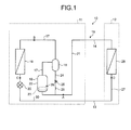
- FIG. 1 is a circuit configuration diagram of a refrigerating cycle device according to the present embodiment.
- a refrigerating cycle device 10 includes a refrigerator unit 11 and a load unit 12 as illustrated in FIG. 1 , and a refrigerant circuit 15 which performs refrigerating cycle operation is formed by connecting these refrigerator unit 11 and load unit 12 by a liquid refrigerant pipe 13 and a gas refrigerant pipe 14.
- Carbon dioxide (CO 2 ) refrigerant is used in the refrigerant circuit 15, and a high pressure side of the refrigerant becomes supercritical pressure.
- the carbon dioxide refrigerant is useful refrigerant because of having advantages such as a low load to environment, being safe without toxicity and combustibility, and a low price. Needless to mention, other refrigerant can be also used under the condition that the high pressure side thereof becomes the supercritical pressure.
- the refrigerator unit 11 includes a compressor 16 to compress the refrigerant, and an oil separator 18, a gas cooler (radiator) 19, and an expansion valve (decompressor) 20 are sequentially connected via a refrigerant discharge pipe 17 on a discharge side of the compressor 16.
- An outlet side of the expansion valve 20 is connected to a refrigerator-side liquid refrigerant pipe 30 where the refrigerant liquefied is circulated, and this refrigerator-side liquid refrigerant pipe 30 is connected to the above-described liquid refrigerant pipe 13.
- a suction side of the compressor 16 is connected to a refrigerant suction pipe 21, and the refrigerant suction pipe 21 is connected to the above-described gas refrigerant pipe 14 via an accumulator (not illustrated).
- the compressor 16 includes a compressing element 23 inside a case 22.
- the compressing element 23 is, for example, a compressing element provided with a low-stage compressing element and a high-stage compressing element and capable of performing two-stage compression.
- the compressing element 23 compresses low-pressure gas refrigerant suctioned via the refrigerant suction pipe 21 and discharges, to the refrigerant discharge pipe 17, high-pressure gas refrigerant boosted up to the supercritical pressure.
- the compressing element 23 is driven by a motor (not illustrated), and can adjust a rotary speed of the compressing element 23 by changing an operational frequency of the motor.
- oil to lubricate respective portions (bearing portions and sliding portions) of the compressing element 23 is stored, and further a sensor 29 to detect an oil amount inside the case 22 is provided.
- the oil separator 18 separates, from the refrigerant, oil contained in the high-pressure (supercritical pressure) gas refrigerant discharged from the compressor 16, and then captures the oil.
- the oil separator 18 includes an oil return tube 24 to return the captured oil to the case 22 of the compressor 16, and the oil return tube 24 is connected to the refrigerant suction pipe 21 via a solenoid valve 25 and a capillary tube (throttle) 26.
- the solenoid valve 25 is opened and closed based on a signal of the above-described sensor 29 that detects the oil amount.
- a gas cooler 19 performs heat exchange between air and the high-temperature high-pressure (supercritical pressure) gas refrigerant discharged from the compressor 16, and cools the gas refrigerant by radiating heat thereof.
- the gas cooler 19 is formed of a fin-and-tube heat exchanger, and a blower fan (not illustrated) to send air to the gas cooler 19 is disposed beside the gas cooler 19 while the details will be described later.
- the expansion valve 20 decompresses (expands) and liquefies the cooled gas refrigerant.
- the load unit 12 includes a load-side pipe 27 which connects the above-described the liquid refrigerant pipe 13 to gas refrigerant pipe 14, and an evaporator (load-side heat exchanger) 28 disposed at the load-side pipe 27.
- the load unit 12 cools a target object by evaporating liquid refrigerant supplied via the liquid refrigerant pipe 13 by using an evaporator 28, and is used as a low-temperature freezer, a showcase, and so on.
- the evaporator 28 is formed of the fin-and-tube heat exchanger same as the gas cooler 19, and the blower fan (not illustrated) to send the air to the evaporator 28 is disposed beside the evaporator 28.
- the air is cooled by removing heat from the blown air, and then evaporating the liquid refrigerant.
- the low-temperature low-pressure gas refrigerant evaporated by the evaporator 28 is suctioned to the compressor 16 via the gas refrigerant pipe 14, accumulator, and refrigerant suction pipe 21, and is compressed again by the compressor 16.
- the load unit 12 having the configuration provided with one evaporator 28 has been described, but it may also have a configuration provided with a plurality of evaporators 28 arranged in parallel.
- an expansion valve 20 is preferably provided at an inlet side (liquid refrigerant pipe 13 side) of each of the evaporators 28 in each of the load-side pipes 27.
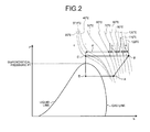
- FIG. 2 is a Mollier chart illustrating the refrigerating cycle of the refrigerant boosted to the supercritical pressure.
- point A indicates a pressure and an enthalpy of the refrigerant on the suction side of the compressor 16.
- point B indicates a pressure and an enthalpy of the refrigerant on an inlet side of the gas cooler 19
- point C indicates the same on an outlet side of the gas cooler 19
- point D indicates the same on the inlet side of the evaporator 28.
- dashed lines in FIG. 2 respectively indicate isotherms.
- an enthalpy amount from 120°C to 100°C, an enthalpy amount from 100°C to 80°C, an enthalpy amount from 80°C to 60°C, and an enthalpy amount from 60°C to approximately 35°C are defined as a, b, c, d respectively as illustrated in FIG. 2
- the enthalpy amounts become a ⁇ b ⁇ c ⁇ d, particularly, the enthalpy amount d from 60°C to approximately 35°C is larger than those of other temperature zones.
- FIG. 3 is a schematic diagram illustrating a gas cooler according to the present embodiment.
- the gas cooler 19 includes, as illustrated in FIG. 3 , a plurality of fin plates 30 extending in a vertical direction, arranged apart from one another substantially in parallel, and a heat transfer tube bundle 33 formed of a plurality of heat transfer tubes passing through the fin plates 30.
- the air flows in a direction orthogonal to the drawing sheet.
- the heat transfer tube bundles 33 are arranged in a single line and multiple stages (12 stages in the present embodiment) in a vertical direction of the fin plates 30, and a plurality (three in the present embodiment) of refrigerant channels 34A, 34B, 34C is formed in parallel by the heat transfer tube bundles 33.
- a flow amount in each of the refrigerant channel is reduced by the refrigerant being distributed to each of the refrigerant channels, and also pressure loss of the refrigerant at the gas cooler 19 is reduced because a channel length of the refrigerant channel is shortened, thereby achieving to improve the coefficient of performance.
- the gas cooler 19 includes an inlet header 36 connected to an inlet pipe 35 (refrigerant discharge pipe 17) passing the oil separator 18, and an outlet header 38 connected to an outlet pipe 37 (refrigerant discharge pipe 17) extending to the expansion valve 20, and the three refrigerant channels 34A, 34B, 34C are formed between the inlet header 36 and the outlet header 38.
- Each of the refrigerant channels 34A, 34B, 34C is formed by connecting four heat transfer tubes, and the refrigerant flows from the upper side to the lower side of the gas cooler 19 in a height direction (vertical direction).
- the refrigerant channels 34A, 34B, 34C include the inlet heat transfer tubes 40A, 40B, 40C respectively connected to the inlet header 36. These inlet heat transfer tubes 40A, 40B, 40C are disposed at an upper portion (1 st , 3 rd , 5 th stages) of the fin plates 30. Further, the refrigerant channels 34A, 34B, 34C include the outlet heat transfer tubes 42A, 42B, 42C respectively connected to the outlet header 38. The outlet heat transfer tubes 42A, 42B, 42C are disposed at a lower portion (8 th , 10 th , 12 th stages) of the fin plates 30.
- the refrigerant channel 34A includes a first intermediate heat transfer tube 41A1 connected to the inlet heat transfer tube 40A via a U-shape tube 43, and a second intermediate heat transfer tube 41A2 connected to the outlet heat transfer tube 42A via a U-shape tube 43.
- the first intermediate heat transfer tube 41A1 is disposed at a position one stage lower than the inlet heat transfer tube 40A
- the second intermediate heat transfer tube 41A2 is disposed at a position one stage above the outlet heat transfer tube 42A.
- the first intermediate heat transfer tube 41A1 and the second intermediate heat transfer tube 41A2 are connected by an intermediate header 44.
- the refrigerant flows in the refrigerant channel 34A from an upper-stage heat transfer tube to a lower-stage heat transfer tube in the order of the inlet heat transfer tube 40A, first intermediate heat transfer tube 41A1, second intermediate heat transfer tube 41A2, and outlet heat transfer tube 42A.
- the refrigerant channel 34B includes a first intermediate heat transfer tube 41B1 connected to the inlet heat transfer tube 40B via a U-shape tube 43, and a second intermediate heat transfer tube 41B2 connected to the outlet heat transfer tube 42B via a U-shape tube 43.
- the first intermediate heat transfer tube 41B1 is disposed at a position one stage lower than the inlet heat transfer tube 40B
- the second intermediate heat transfer tube 41B2 is disposed at a position one stage above the outlet heat transfer tube 42B.
- the first intermediate heat transfer tube 41B1 and second intermediate heat transfer tube 41B2 are connected by the above-described intermediate header 44.
- the refrigerant flows in the refrigerant channel 34B from an upper-stage heat transfer tube to a lower-stage heat transfer tube in the order of the inlet heat transfer tube 40B, first intermediate heat transfer tube 41B1, second intermediate heat transfer tube 41B2, and outlet heat transfer tube 42B.
- the refrigerant channel 34C includes a first intermediate heat transfer tube 41C1 connected to the inlet heat transfer tube 40C via a U-shape tube 43, and a second intermediate heat transfer tube 41C2 connected to the outlet heat transfer tube 42C via a U-shape tube 43.
- the first intermediate heat transfer tube 41C1 is disposed at a position one stage lower than the inlet heat transfer tube 40C, and the second intermediate heat transfer tube 41C2 is disposed at a position one stage above the outlet heat transfer tube 42C. Further, the first intermediate heat transfer tube 41C1 and the second intermediate heat transfer tube 41C2 are connected by the above-described intermediate header 44. With this configuration, the refrigerant flows in the refrigerant channel 34C from an upper-stage heat transfer tube to a lower-stage heat transfer tube in the order of the inlet heat transfer tube 40C, first intermediate heat transfer tube 41C1, second intermediate heat transfer tube 41C2, and outlet heat transfer tube 42C.
- the gas cooler 19 includes an upper heat exchange unit 45 and a lower heat exchange unit 46 which are plural sections (two sections in the present embodiment) divided in a height direction (vertical direction).
- the refrigerant channels 34A, 34B, 34C are respectively formed so as to perform sequential circulation from the upper heat exchange unit 45 to the lower heat exchange unit 46. More specifically, the refrigerant channel 34A has the inlet heat transfer tube 40A and the first intermediate heat transfer tube 41A1 disposed on the upper heat exchange unit 45, and has the second intermediate heat transfer tube 41A2 and the outlet heat transfer tube 42A disposed on the lower heat exchange unit 46 via the intermediate header 44.
- the refrigerant channel 34B has the inlet heat transfer tube 40B and the first intermediate heat transfer tube 41B1 disposed on the upper heat exchange unit 45, and has the second intermediate heat transfer tube 41B2 and the outlet heat transfer tube 42B disposed on the lower heat exchange unit 46.
- the refrigerant channel 34C has the inlet heat transfer tube 40C and the first intermediate heat transfer tube 41C1 disposed on the upper heat exchange unit 45, and has the second intermediate heat transfer tube 41C2 and the outlet heat transfer tube 42C disposed on the lower heat exchange unit 46.
- the refrigerant channels 34A, 34B, 34C respectively include the inlet heat transfer tubes 40A, 40B, 40C disposed on the upper portion side of the fin plates 30, and also include the outlet heat transfer tubes 42A, 42B, 42C disposed on the lower portion side of the fin plates 30. Therefore, the refrigerant channels 42A, 42B, 42C of the respective refrigerant channels 34A, 34B, 34C can be disposed apart from the inlet heat transfer tubes 40A, 40B, 40C of own or other refrigerant channels 34A, 34B, 34C.
- the refrigerant channels 34A, 34B, 34C respectively include the first intermediate heat transfer tubes (intermediate heat transfer tubes) 41A1, 41B1, 41C1 and the second intermediate heat transfer tubes (intermediate heat transfer tubes) 41A2, 41B2, 41C2 between the inlet heat transfer tubes 40A, 40B, 40C and the outlet heat transfer tubes 42A, 42B, 42C. Therefore, the inlet heat transfer tubes 40A, 40B, 40C and the outlet heat transfer tubes 42A, 42B, 42C are not disposed adjacent to each other. Therefore, the refrigerant outlet temperature is suppressed from being increased by the high-temperature refrigerant (e.g., 100 to 120°C) flowing in the inlet heat transfer tubes 40A, 40B, 40C. Therefore, the coefficient of performance in the refrigerating cycle can be improved.
- the high-temperature refrigerant e.g., 100 to 120°C
- the refrigerant flows from an upper-stage heat transfer tube to a lower-stage heat transfer tube in the order of the inlet heat transfer tubes 40A, 40B, 40C, first intermediate heat transfer tubes 41A1, 41B1, 41C1, second intermediate heat transfer tubes 41A2, 41B2, 41C2, and outlet heat transfer tubes 42A, 42B, 42C.
- the refrigerant boosted up to the supercritical pressure is not condensed at the gas cooler 19, but density (specific gravity) of the refrigerant gas is increased due to cooling.
- the refrigerant is gradually cooled from an upper-stage heat transfer tube to a lower-stage heat transfer tube. Therefore, a temperature difference of the refrigerant flowing in adjacent heat transfer tubes can be set at a predetermined temperature or less, and heat transfer between the adjacent heat transfer tubes can be suppressed.
- a temperature difference between an outlet and an inlet of the gas cooler 19 is 85°C in the present embodiment. Therefore, the temperature difference of the refrigerant flowing in the adjacent heat transfer tubes can be reduced to approximately 20°C to 25°C. Further, since the temperature difference between the outlet and the inlet of the gas cooler 19 is normally about 60°C, the temperature difference of the refrigerant between the adjacent heat transfer tubes can be reduced to about 15°C in this case.
- the gas cooler 19 includes the vertically divided sections which are the upper heat exchange unit 45 and the lower heat exchange unit 46, and the refrigerant channels 34A, 34B, 34C each have the configuration in which the refrigerant sequentially flows from the upper heat exchange unit 45 to the lower heat exchange unit 46. Therefore, a temperature gradient in which the temperature is decreased from the upper heat exchange unit 45 to the lower heat exchange unit 46. As a result, temperature unevenness in the gas cooler 19 can be reduced.
- the refrigerant channels 34A, 34B, 34C include the first intermediate heat transfer tubes 41A1, 41B1, 41C1 respectively connected to the inlet heat transfer tubes 40A, 40B, 40C, and the second intermediate heat transfer tubes 41A2, 41B2, 41C2 respectively connected to the outlet heat transfer tubes 42A, 42B, 42C, and include the intermediate header 44 to which all of the first intermediate heat transfer tubes 41A1, 41B1, 41C1 and the second intermediate heat transfer tubes 41A2, 41B2, 41C2 of the respective refrigerant channels 34A, 34B, 34C are connected.
- FIG. 4 is a diagram illustrating a gas cooler according to the modified example.
- the refrigerant channels 34A, 34B, 34C have the first intermediate heat transfer tubes 41A1, 41B1, 41C1 and the second intermediate heat transfer tubes 41A2, 41B2, 41C2 respectively connected via connection tubes 47A, 47B, 47C.
- the gas cooler 50 can be downsized because the intermediate header 44 is not needed.
- the refrigerant channels 34A, 34B, 34C are respectively configured to include two heat transfer tubes respectively from the first intermediate heat transfer tubes 41A1, 41B1, 41C1 and the second intermediate heat transfer tubes 41A2, 41B2, 41C2 as the intermediate heat transfer tubes.
- the number of the intermediate heat transfer tubes may be suitably changed depending on a refrigerant flow rate and a size of the fin plate 30.
- At least one intermediate heat transfer tube is to be provided, and the refrigerant channel may have a minimum configuration in which three heat transfer tubes including the inlet heat transfer tube, intermediate heat transfer tube, and outlet heat transfer tube are provided such that the refrigerant flows one and half round.
- the outlet of the refrigerant is positioned on an opposite side of the inlet of the refrigerant in an extending direction of the heat transfer tube.
- a temperature difference between the refrigerant flowing in the heat transfer tubes adjacent to each other can be reduced to about 25°C to 30°C because the temperature difference between the outlet and the inlet of the gas cooler 19 is 85°C ( FIG. 2 ).
- a temperature difference between the refrigerant flowing in the heat transfer tubes adjacent to each other sometimes becomes about 30°C, compared to a case of forming the above-described refrigerant channel with four heat transfer tubes (four paths).
- the temperature difference between the outlet and the inlet of the gas cooler 19 is normally about 60°C, the temperature difference between the refrigerant flowing in the heat transfer tubes adjacent to each other can be reduced to about 20°C.
- an interval (pitch) between the heat transfer tubes is set equal, but for example, an interval between the upper heat exchange unit 45 and the lower heat exchange unit 46 and an interval between the first intermediate heat transfer tube 41C1 of the refrigerant channel 34C and the second intermediate heat transfer tube 41A2 of the refrigerant channel 34A may be formed wider by an interval of one heat transfer tube.
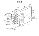
- FIG. 5 is a schematic diagram illustrating the gas cooler according to the different embodiment.
- gas coolers 19, 50 have a configuration in which a heat transfer tube bundle 33 formed in a single line is provided, but the present embodiment is different in that heat transfer tube bundles 33 formed in multiple lines are provided.
- a description of components same as the above-described gas cooler 19 will be omitted by denoting the components by the same reference signs.
- a gas cooler 60 includes heat transfer tube bundles 33 formed of heat transfer tubes arranged in multiple lines and multiple stages (two lines and six stages in the present embodiment).
- the heat transfer tube bundles 33 in the respective lines are formed to have different height positions, and a heat transfer tube positioned on a leeward-side line is placed slightly higher than a heat transfer tube positioned on a windward-side line.
- the gas cooler 60 includes three refrigerant channels 34A, 34B, 34C formed in parallel by the heat transfer tube bundles 33.
- the refrigerant channels 34A, 34B, 34C include inlet heat transfer tubes 40A, 40B, 40C respectively connected to an inlet header 36.
- the inlet heat transfer tubes 40A, 40B, 40C are disposed on the leeward-side line at an upper portion (1 st , 2 nd , 3 rd stages) of fin plates 30
- the refrigerant channels 34A, 34B, 34C include outlet heat transfer tubes 42A, 42B, 42C respectively connected to an outlet header 38.
- These outlet heat transfer tubes 42A, 42B, 42C are disposed on the windward-side line at a lower portion (4 th , 5 th , 6 th stages) of the fin plates 30.
- the refrigerant channel 34A includes a first intermediate heat transfer tube 41A1 connected to the inlet heat transfer tube 40A via a U-shape tube (not illustrated), and a second intermediate heat transfer tube 41A2 connected to the outlet heat transfer tube 42A via a U-shape tube (not illustrated).
- the first intermediate heat transfer tube 41A1 is disposed at an uppermost stage in the line (windward-side line) next to the inlet heat transfer tube 40A
- the second intermediate heat transfer tube 41A2 is disposed at the lower portion (4 th stage) in the line (leeward-side line) next to the outlet heat transfer tube 42A.
- the first intermediate heat transfer tube 41A1 and the second intermediate heat transfer tube 41A2 are connected by an intermediate header 44.
- the refrigerant flows in the refrigerant channel 34A from an upper-stage heat transfer tube to a lower-stage heat transfer tube in the order of the inlet heat transfer tube 40A, first intermediate heat transfer tube 41A1, second intermediate heat transfer tube 41A2, and outlet heat transfer tube 42A.
- the refrigerant channel 34B includes a first intermediate heat transfer tube 41B1 connected to the inlet heat transfer tube 40B via the U-shape tube (not illustrated), and a second intermediate heat transfer tube 41B2 connected to the outlet heat transfer tube 42B via the U-shape tube (not illustrated).
- the first intermediate heat transfer tube 41B1 is disposed at the upper portion (2 nd stage) in the line (windward-side line) next to the inlet heat transfer tube 40B
- the second intermediate heat transfer tube 41B2 is disposed at the lower portion (5 th stage) in the line (leeward-side line) next to the outlet heat transfer tube 42B.
- the refrigerant channel 34C includes a first intermediate heat transfer tube 41C1 connected to the inlet heat transfer tube 40C via the U-shape tube, and a second intermediate heat transfer tube 41C2 connected to the outlet heat transfer tube 42C via the U-shape tube (not illustrated).
- the first intermediate heat transfer tube 41C1 is disposed at the upper portion (3 rd stage) in the line (windward-side line) next to the inlet heat transfer tube 40C
- the second intermediate heat transfer tube 41C2 is disposed at the lower portion (6 th stage) in the line (leeward-side line) next to the outlet heat transfer tube 42C.
- the refrigerant flows from an upper-stage heat transfer tube to a lower-stage heat transfer tube in the order of the inlet heat transfer tubes 40B, 40C, first intermediate heat transfer tubes 41B1, 41C1, second intermediate heat transfer tubes 41B2, 41C2, and outlet heat transfer tubes 42B, 42C.
- the gas cooler 60 includes an upper heat exchange unit 45 and a lower heat exchange unit 46 which are two sections divided in a height direction (vertical direction).
- the refrigerant channels 34A, 34B, 34C are respectively formed so as to perform sequential circulation from the upper heat exchange unit 45 to the lower heat exchange unit 46. More specifically, the refrigerant channel 34A has the inlet heat transfer tube 40A and the first intermediate heat transfer tube 41A1 disposed on the upper heat exchange unit 45, and has the second intermediate heat transfer tube 41A2 and the outlet heat transfer tube 42A disposed on the lower heat exchange unit 46 via the intermediate header 44.
- the refrigerant channel 34B has the inlet heat transfer tube 40B and the first intermediate heat transfer tube 41B1 disposed on the upper heat exchange unit 45, and has the second intermediate heat transfer tube 41B2 and the outlet heat transfer tube 42B disposed on the lower heat exchange unit 46.
- the refrigerant channel 34C has the inlet heat transfer tube 40C and the first intermediate heat transfer tube 41C1 disposed on the upper heat exchange unit 45, and has the second intermediate heat transfer tube 41C2 and the outlet heat transfer tube 42C disposed on the lower heat exchange unit 46.
- the heat transfer tube bundles 33 are inserted into the fin plates 30 arranged in two lines and six stages, and inlet heat transfer tubes 40A, 40B, 40C of the respective refrigerant channels 34A, 34B, 34C are disposed closer to the leeward-side line than the outlet heat transfer tubes 42A, 42B, 42C are. Therefore, when heat is exchanged with the refrigerant flowing in the heat transfer tubes, influence of heat held by air can be reduced and increase of the refrigerant outlet temperature can be suppressed
- FIGS. 6 and 7 are schematic diagrams illustrating gas coolers according to the modified examples.
- gas coolers 65, 70 components same as the above-described gas coolers 19, 60 will be denoted by the same reference signs, and the description therefor will be omitted.
- the gas cooler 65 has the refrigerant channels 34A, 34B, 34C in which the first intermediate heat transfer tubes 41A1, 41B1, 41C1 and the second intermediate heat transfer tubes 41A2, 41B2, 41C2 are respectively connected via connection tubes 51A, 51B, 51C.
- the gas cooler 65 can be downsized because the intermediate header 44 is not needed.
- arrangement of the respective heat transfer tubes can be suitably changed under the condition that the inlet heat transfer tubes 40A, 40B, 40C are not disposed next to the outlet heat transfer tubes 42A, 42B, 42C and the respective refrigerant channels 34A, 34B, 34C are configured such that the refrigerant flows from an upper-stage heat transfer tube to a lower-stage heat transfer tube.
- the inlet heat transfer tubes 40A, 40B, 40C are disposed in the leeward-side lines of the gas cooler 70, and one inlet heat transfer tube 40B may be disposed at the uppermost stage in the windward-side line.
- outlet heat transfer tubes 42A, 42B, 42C are not needed to be disposed on the windward-side lines, and one outlet heat transfer tube 42B may be disposed at a lowermost line in the leeward-side line.
- an intermediate header 44 is not provided same as the above-described gas cooler 65, and the first intermediate heat transfer tubes 41A1, 41B1, 41C1 and the second intermediate heat transfer tubes 41A2, 41B2, 41C2 are connected via connection tubes 52A, 52B, 52C.
- the intermediate header 44 may be provided instead of the connection tubes 52A, 52B, 52C.
Landscapes
- Engineering & Computer Science (AREA)
- Physics & Mathematics (AREA)
- Thermal Sciences (AREA)
- Mechanical Engineering (AREA)
- General Engineering & Computer Science (AREA)
- Geometry (AREA)
- Heat-Exchange Devices With Radiators And Conduit Assemblies (AREA)
- Details Of Heat-Exchange And Heat-Transfer (AREA)
Abstract
Description
- The present invention relates to a radiator which cools refrigerant boosted up to supercritical pressure by radiating heat thereof, and a refrigerating cycle device including the radiator.
- Generally, there is a known refrigerating cycle device including a compressor which boosts refrigerant up to supercritical pressure by using CO2(carbon dioxide) as the refrigerant, and a radiator which cools the refrigerant discharged from the compressor by radiating heat thereof (refer to
Patent Literature 1, for example). In this type of refrigerating cycle device, a fin-and-tube heat exchanger is used as a radiator so as to improve efficiency in heat exchange. The fin-and-tube heat exchanger includes a plurality fin plates arranged at a predetermined interval, and a plurality of heat transfer tubes which is inserted into the fin plates and allows the refrigerant to flow inside thereof. Further, according to the fin-and-tube heat exchanger in the related arts, there is a known technology in which a plurality of refrigerant channels formed in parallel is provided to improve cooling (heating) performance (refer to Patent Literature 2). -
- Patent Literature 1: Japanese Laid-open Patent Publication No.
2007-232365 - Patent Literature 2: Japanese Laid-open Patent Publication No.
7-208822 - Meanwhile, according to a configuration in which refrigerant is boosted up to supercritical pressure, the refrigerant is cooled by the radiator but not condensed, and the refrigerant circulates in the radiator as gas refrigerant that performs sensible heat change. In order to improve a coefficient of performance (COP) of a refrigerating cycle, a refrigerant outlet temperature is preferably lower in each of refrigerant channels of the radiator.
- However, according to the configuration in the related art, an outlet heat transfer tube of a refrigerant channel is disposed adjacent to an inlet heat transfer tube of own or other refrigerant channel. Therefore, there is a risk that the refrigerant outlet temperature may be increased by high-temperature refrigerant flowing in the inlet heat transfer tube.
- The present invention is made in view of the above-described situation, and is directed to providing a radiator and a refrigerating cycle device, in which increase of a refrigerant outlet temperature at a refrigerant channel is suppressed.
- According to an aspect of the present invention, a radiator which radiates heat of refrigerant boosted up to supercritical pressure, comprises: a plurality of fin plates extending in a vertical direction and arranged at a predetermined interval; and a plurality of refrigerant channels formed in parallel by a heat transfer tube bundle inserted into the fin plates in multiple stages. Each of the plurality of refrigerant channels includes an inlet heat transfer tube disposed at an upper portion of the fin plates, an outlet heat transfer tube disposed at a lower portion of the fin plates, and an intermediate heat transfer tube disposed between the inlet heat transfer tube and the outlet heat transfer tube.
- According to this configuration, each of the plurality of refrigerant channels includes the inlet heat transfer tube on upper portion side of the fin plates and also includes the outlet heat transfer tube on the lower portion side of the fin plates. Therefore, the outlet heat transfer tube of a refrigerant channel can be disposed apart from the inlet heat transfer tube of own or other refrigerant channel. Further, since the intermediate heat transfer tube is disposed between the inlet heat transfer tube and the outlet heat transfer tube, the inlet heat transfer tube is prevented from being disposed adjacent to the outlet heat transfer tube. Therefore, the refrigerant outlet temperature is suppressed from being increased by high-temperature refrigerant flowing in the inlet heat transfer tube, thereby achieving to improve a coefficient of performance in the refrigerating cycle.
- Advantageously, in the radiator, the refrigerant flows from an upper-stage heat transfer tube to a lower-stage heat transfer tube in each of the refrigerant channels. The refrigerant boosted up to the supercritical pressures is not condensed at the time of passing the radiator, but density (specific gravity) of the refrigerant gas is increased due to cooling. Therefore, circulation of the refrigerant is accelerated by the gravity by configuring the refrigerant channel such that the refrigerant flows from an upper-stage heat transfer tube to a lower-stage heat transfer tube. As a result, heat exchange efficiency can be improved.
- Advantageously, the radiator further includes a plurality of heat exchange units, the radiator being vertically divided. The refrigerant sequentially flows from an upper heat exchange unit to a lower heat exchange unit in each of the refrigerant channels. With this configuration, temperature unevenness inside the radiator can be suppressed because a temperature gradient in which the temperature is decreased from the upper heat exchange unit to the lower heat exchange unit is formed.
- Advantageously, in the radiator, each of the refrigerant channels includes a first intermediate heat transfer tube connected to the inlet heat transfer tube, a second intermediate heat transfer tube connected to the outlet heat transfer tube, and an intermediate header connected to all of the first intermediate heat transfer tubes and the second intermediate heat transfer tubes of the respective refrigerant channels. With this configuration, the refrigerant can be properly distributed even in the case where the refrigerant is not properly distributed in the inlet heat transfer tubes of the refrigerant channels because the refrigerant is once gathered at the intermediate header and then distributed again to respective refrigerant channels.
- Advantageously, in the radiator, the heat transfer tube bundle is inserted into the fin plates in multiple lines and multiple stages, and the inlet heat transfer tube is disposed in a line more leeward than the outlet heat transfer tube. With this configuration, influence of the heat held by the air can be suppressed when the heat is exchanged with the refrigerant, and also increase of the refrigerant outlet temperature can be suppressed. Also, advantageously, in the radiator, the refrigerant is carbon dioxide refrigerant.
- According to another aspect of the present invention, a refrigerating cycle device comprising a refrigerant circuit in which any one of the above radiator, a compressor configured to boost refrigerant up to supercritical pressure, a decompressor, and a load-side heat exchanger are connected via pipe. With this configuration, increase of the refrigerant outlet temperature of the radiator can be suppressed, thereby achieving to provide the refrigerating cycle device having an improved coefficient of performance in the refrigerating cycle.
- According to the present invention, each of a plurality of refrigerant channels includes the inlet heat transfer tube on an upper portion side of the fin plates and also includes the outlet heat transfer tube on a lower portion side of the fin plates. Therefore, the outlet heat transfer tube of a refrigerant channel can be disposed apart from the inlet heat transfer tube of own or other refrigerant channel. Further, since the intermediate heat transfer tube is disposed between the inlet heat transfer tube and the outlet heat transfer tube, the inlet heat transfer tube is prevented from being disposed adjacent to the outlet heat transfer tube. Therefore, the refrigerant outlet temperature is suppressed from being increased by high-temperature refrigerant flowing in the inlet heat transfer tube, thereby achieving to improve a coefficient of performance in the refrigerating cycle.
-
-
FIG. 1 is a circuit configuration diagram of a refrigerating cycle device according to a present embodiment. -
FIG. 2 is a Mollier chart illustrating a refrigerating cycle of refrigerant boosted to supercritical pressure. -
FIG. 3 is a schematic diagram illustrating a radiator according to the present embodiment. -
FIG. 4 is a schematic diagram illustrating a radiator according to a modified example. -
FIG. 5 is a schematic diagram illustrating a radiator according to a different embodiment. -
FIG. 6 is a schematic diagram illustrating a radiator according to a modified example. -
FIG. 7 is a schematic diagram illustrating a radiator according to a different modified example. - Embodiments according to the present invention will be described below with reference to the drawings. Note that the present invention is not limited to the following embodiments. Further, components in the following embodiments include the components which can be replaced and easily achieved by a person skilled in the art or which are substantially equivalent.
-
FIG. 1 is a circuit configuration diagram of a refrigerating cycle device according to the present embodiment. A refrigeratingcycle device 10 includes arefrigerator unit 11 and aload unit 12 as illustrated inFIG. 1 , and arefrigerant circuit 15 which performs refrigerating cycle operation is formed by connecting theserefrigerator unit 11 andload unit 12 by aliquid refrigerant pipe 13 and agas refrigerant pipe 14. Carbon dioxide (CO2) refrigerant is used in therefrigerant circuit 15, and a high pressure side of the refrigerant becomes supercritical pressure. The carbon dioxide refrigerant is useful refrigerant because of having advantages such as a low load to environment, being safe without toxicity and combustibility, and a low price. Needless to mention, other refrigerant can be also used under the condition that the high pressure side thereof becomes the supercritical pressure. - The
refrigerator unit 11 includes acompressor 16 to compress the refrigerant, and anoil separator 18, a gas cooler (radiator) 19, and an expansion valve (decompressor) 20 are sequentially connected via arefrigerant discharge pipe 17 on a discharge side of thecompressor 16. An outlet side of theexpansion valve 20 is connected to a refrigerator-sideliquid refrigerant pipe 30 where the refrigerant liquefied is circulated, and this refrigerator-sideliquid refrigerant pipe 30 is connected to the above-describedliquid refrigerant pipe 13. Further, a suction side of thecompressor 16 is connected to arefrigerant suction pipe 21, and therefrigerant suction pipe 21 is connected to the above-describedgas refrigerant pipe 14 via an accumulator (not illustrated). - The
compressor 16 includes a compressingelement 23 inside acase 22. The compressingelement 23 is, for example, a compressing element provided with a low-stage compressing element and a high-stage compressing element and capable of performing two-stage compression. The compressingelement 23 compresses low-pressure gas refrigerant suctioned via therefrigerant suction pipe 21 and discharges, to therefrigerant discharge pipe 17, high-pressure gas refrigerant boosted up to the supercritical pressure. The compressingelement 23 is driven by a motor (not illustrated), and can adjust a rotary speed of the compressingelement 23 by changing an operational frequency of the motor. Further, inside thecase 22, oil to lubricate respective portions (bearing portions and sliding portions) of the compressingelement 23 is stored, and further asensor 29 to detect an oil amount inside thecase 22 is provided. - The
oil separator 18 separates, from the refrigerant, oil contained in the high-pressure (supercritical pressure) gas refrigerant discharged from thecompressor 16, and then captures the oil. Theoil separator 18 includes anoil return tube 24 to return the captured oil to thecase 22 of thecompressor 16, and theoil return tube 24 is connected to therefrigerant suction pipe 21 via asolenoid valve 25 and a capillary tube (throttle) 26. In the present embodiment, thesolenoid valve 25 is opened and closed based on a signal of the above-describedsensor 29 that detects the oil amount. - A
gas cooler 19 performs heat exchange between air and the high-temperature high-pressure (supercritical pressure) gas refrigerant discharged from thecompressor 16, and cools the gas refrigerant by radiating heat thereof. Thegas cooler 19 is formed of a fin-and-tube heat exchanger, and a blower fan (not illustrated) to send air to thegas cooler 19 is disposed beside thegas cooler 19 while the details will be described later. Theexpansion valve 20 decompresses (expands) and liquefies the cooled gas refrigerant. - On the other hand, the
load unit 12 includes a load-side pipe 27 which connects the above-described the liquidrefrigerant pipe 13 togas refrigerant pipe 14, and an evaporator (load-side heat exchanger) 28 disposed at the load-side pipe 27. Theload unit 12 cools a target object by evaporating liquid refrigerant supplied via the liquidrefrigerant pipe 13 by using anevaporator 28, and is used as a low-temperature freezer, a showcase, and so on. Theevaporator 28 is formed of the fin-and-tube heat exchanger same as thegas cooler 19, and the blower fan (not illustrated) to send the air to theevaporator 28 is disposed beside theevaporator 28. In theevaporator 28, the air is cooled by removing heat from the blown air, and then evaporating the liquid refrigerant. The low-temperature low-pressure gas refrigerant evaporated by theevaporator 28 is suctioned to thecompressor 16 via thegas refrigerant pipe 14, accumulator, andrefrigerant suction pipe 21, and is compressed again by thecompressor 16. Meanwhile, according to the present embodiment, theload unit 12 having the configuration provided with oneevaporator 28 has been described, but it may also have a configuration provided with a plurality ofevaporators 28 arranged in parallel. In this case, anexpansion valve 20 is preferably provided at an inlet side (liquidrefrigerant pipe 13 side) of each of theevaporators 28 in each of the load-side pipes 27. - By the way, according to the refrigerating
cycle device 10 of the present embodiment, the refrigerant is boosted up to the supercritical pressure. Therefore, the refrigerant is not condensed even though cooled by thegas cooler 19, and circulates as the gas refrigerant in thegas cooler 19 that performs sensible heat change.FIG. 2 is a Mollier chart illustrating the refrigerating cycle of the refrigerant boosted to the supercritical pressure. InFIG. 2 , point A indicates a pressure and an enthalpy of the refrigerant on the suction side of thecompressor 16. In the same manner, point B indicates a pressure and an enthalpy of the refrigerant on an inlet side of thegas cooler 19, point C indicates the same on an outlet side of thegas cooler 19, and point D indicates the same on the inlet side of theevaporator 28. Further, dashed lines inFIG. 2 respectively indicate isotherms. - As described above, sensible heat change is performed by cooling in the
gas cooler 19. In this case, assuming that an enthalpy amount from 120°C to 100°C, an enthalpy amount from 100°C to 80°C, an enthalpy amount from 80°C to 60°C, and an enthalpy amount from 60°C to approximately 35°C are defined as a, b, c, d respectively as illustrated inFIG. 2 , the enthalpy amounts become a < b < c <d, particularly, the enthalpy amount d from 60°C to approximately 35°C is larger than those of other temperature zones. Therefore, when the refrigerant outlet temperature at thegas cooler 19 is more cooled to a lower temperature, a refrigerating effect can be increased by a corresponding amount, and a coefficient of performance (COP) can be improved. In the following, a configuration of thegas cooler 19 which can cool the refrigerant outlet temperature to a lower temperature will be described. -
FIG. 3 is a schematic diagram illustrating a gas cooler according to the present embodiment. Thegas cooler 19 includes, as illustrated inFIG. 3 , a plurality offin plates 30 extending in a vertical direction, arranged apart from one another substantially in parallel, and a heattransfer tube bundle 33 formed of a plurality of heat transfer tubes passing through thefin plates 30. The air flows in a direction orthogonal to the drawing sheet. According to the present embodiment, the heat transfer tube bundles 33 are arranged in a single line and multiple stages (12 stages in the present embodiment) in a vertical direction of thefin plates 30, and a plurality (three in the present embodiment) ofrefrigerant channels gas cooler 19 is reduced because a channel length of the refrigerant channel is shortened, thereby achieving to improve the coefficient of performance. - The
gas cooler 19 includes aninlet header 36 connected to an inlet pipe 35 (refrigerant discharge pipe 17) passing theoil separator 18, and anoutlet header 38 connected to an outlet pipe 37 (refrigerant discharge pipe 17) extending to theexpansion valve 20, and the threerefrigerant channels inlet header 36 and theoutlet header 38. Each of therefrigerant channels gas cooler 19 in a height direction (vertical direction). - The
refrigerant channels heat transfer tubes inlet header 36. These inletheat transfer tubes fin plates 30. Further, therefrigerant channels heat transfer tubes outlet header 38. The outletheat transfer tubes fin plates 30. - The
refrigerant channel 34A includes a first intermediate heat transfer tube 41A1 connected to the inletheat transfer tube 40A via aU-shape tube 43, and a second intermediate heat transfer tube 41A2 connected to the outletheat transfer tube 42A via aU-shape tube 43. The first intermediate heat transfer tube 41A1 is disposed at a position one stage lower than the inletheat transfer tube 40A, and the second intermediate heat transfer tube 41A2 is disposed at a position one stage above the outletheat transfer tube 42A. Further, the first intermediate heat transfer tube 41A1 and the second intermediate heat transfer tube 41A2 are connected by anintermediate header 44. With this configuration, the refrigerant flows in therefrigerant channel 34A from an upper-stage heat transfer tube to a lower-stage heat transfer tube in the order of the inletheat transfer tube 40A, first intermediate heat transfer tube 41A1, second intermediate heat transfer tube 41A2, and outletheat transfer tube 42A. - In the same manner, the
refrigerant channel 34B includes a first intermediate heat transfer tube 41B1 connected to the inletheat transfer tube 40B via aU-shape tube 43, and a second intermediate heat transfer tube 41B2 connected to the outletheat transfer tube 42B via aU-shape tube 43. The first intermediate heat transfer tube 41B1 is disposed at a position one stage lower than the inletheat transfer tube 40B, and the second intermediate heat transfer tube 41B2 is disposed at a position one stage above the outletheat transfer tube 42B. Further, the first intermediate heat transfer tube 41B1 and second intermediate heat transfer tube 41B2 are connected by the above-describedintermediate header 44. With this configuration, the refrigerant flows in therefrigerant channel 34B from an upper-stage heat transfer tube to a lower-stage heat transfer tube in the order of the inletheat transfer tube 40B, first intermediate heat transfer tube 41B1, second intermediate heat transfer tube 41B2, and outletheat transfer tube 42B. Also, therefrigerant channel 34C includes a first intermediate heat transfer tube 41C1 connected to the inletheat transfer tube 40C via aU-shape tube 43, and a second intermediate heat transfer tube 41C2 connected to the outletheat transfer tube 42C via aU-shape tube 43. The first intermediate heat transfer tube 41C1 is disposed at a position one stage lower than the inletheat transfer tube 40C, and the second intermediate heat transfer tube 41C2 is disposed at a position one stage above the outletheat transfer tube 42C. Further, the first intermediate heat transfer tube 41C1 and the second intermediate heat transfer tube 41C2 are connected by the above-describedintermediate header 44. With this configuration, the refrigerant flows in therefrigerant channel 34C from an upper-stage heat transfer tube to a lower-stage heat transfer tube in the order of the inletheat transfer tube 40C, first intermediate heat transfer tube 41C1, second intermediate heat transfer tube 41C2, and outletheat transfer tube 42C. - Further, the
gas cooler 19 includes an upperheat exchange unit 45 and a lowerheat exchange unit 46 which are plural sections (two sections in the present embodiment) divided in a height direction (vertical direction). Therefrigerant channels heat exchange unit 45 to the lowerheat exchange unit 46. More specifically, therefrigerant channel 34A has the inletheat transfer tube 40A and the first intermediate heat transfer tube 41A1 disposed on the upperheat exchange unit 45, and has the second intermediate heat transfer tube 41A2 and the outletheat transfer tube 42A disposed on the lowerheat exchange unit 46 via theintermediate header 44. In the same manner, therefrigerant channel 34B has the inletheat transfer tube 40B and the first intermediate heat transfer tube 41B1 disposed on the upperheat exchange unit 45, and has the second intermediate heat transfer tube 41B2 and the outletheat transfer tube 42B disposed on the lowerheat exchange unit 46. Further, therefrigerant channel 34C has the inletheat transfer tube 40C and the first intermediate heat transfer tube 41C1 disposed on the upperheat exchange unit 45, and has the second intermediate heat transfer tube 41C2 and the outletheat transfer tube 42C disposed on the lowerheat exchange unit 46. - Thus, according to the present configuration, the
refrigerant channels heat transfer tubes fin plates 30, and also include the outletheat transfer tubes fin plates 30. Therefore, therefrigerant channels refrigerant channels heat transfer tubes refrigerant channels refrigerant channels heat transfer tubes heat transfer tubes heat transfer tubes heat transfer tubes heat transfer tubes - Further, in the respective
refrigerant channels heat transfer tubes heat transfer tubes gas cooler 19, but density (specific gravity) of the refrigerant gas is increased due to cooling. Therefore, circulation of the refrigerant is accelerated by gravity by forming therefrigerant channels - Further, in the
refrigerant channels FIG. 2 , a temperature difference between an outlet and an inlet of thegas cooler 19 is 85°C in the present embodiment. Therefore, the temperature difference of the refrigerant flowing in the adjacent heat transfer tubes can be reduced to approximately 20°C to 25°C. Further, since the temperature difference between the outlet and the inlet of thegas cooler 19 is normally about 60°C, the temperature difference of the refrigerant between the adjacent heat transfer tubes can be reduced to about 15°C in this case. - Further, the
gas cooler 19 includes the vertically divided sections which are the upperheat exchange unit 45 and the lowerheat exchange unit 46, and therefrigerant channels heat exchange unit 45 to the lowerheat exchange unit 46. Therefore, a temperature gradient in which the temperature is decreased from the upperheat exchange unit 45 to the lowerheat exchange unit 46. As a result, temperature unevenness in thegas cooler 19 can be reduced. - Further, the
refrigerant channels heat transfer tubes heat transfer tubes intermediate header 44 to which all of the first intermediate heat transfer tubes 41A1, 41B1, 41C1 and the second intermediate heat transfer tubes 41A2, 41B2, 41C2 of the respectiverefrigerant channels heat transfer tubes refrigerant channels intermediate header 44 and then distributed again to the respectiverefrigerant channels gas cooler 19. - Next, a modified example of the present embodiment will be described.
FIG. 4 is a diagram illustrating a gas cooler according to the modified example. In thisgas cooler 50, components same as the above-describedgas cooler 19 will be denoted by the same reference signs, and the description therefor will be omitted. In thegas cooler 50, therefrigerant channels connection tubes gas cooler 50 can be downsized because theintermediate header 44 is not needed. - According to the above-described embodiment, the
refrigerant channels fin plate 30. At least one intermediate heat transfer tube is to be provided, and the refrigerant channel may have a minimum configuration in which three heat transfer tubes including the inlet heat transfer tube, intermediate heat transfer tube, and outlet heat transfer tube are provided such that the refrigerant flows one and half round. In this configuration, the outlet of the refrigerant is positioned on an opposite side of the inlet of the refrigerant in an extending direction of the heat transfer tube. In the case of thus configuring the refrigerant channel with three paths, a temperature difference between the refrigerant flowing in the heat transfer tubes adjacent to each other can be reduced to about 25°C to 30°C because the temperature difference between the outlet and the inlet of thegas cooler 19 is 85°C (FIG. 2 ). In this configuration, there may be a case in which a temperature difference between the refrigerant flowing in the heat transfer tubes adjacent to each other sometimes becomes about 30°C, compared to a case of forming the above-described refrigerant channel with four heat transfer tubes (four paths). Further, since the temperature difference between the outlet and the inlet of thegas cooler 19 is normally about 60°C, the temperature difference between the refrigerant flowing in the heat transfer tubes adjacent to each other can be reduced to about 20°C. - Further, according to the above-described embodiment, an interval (pitch) between the heat transfer tubes is set equal, but for example, an interval between the upper
heat exchange unit 45 and the lowerheat exchange unit 46 and an interval between the first intermediate heat transfer tube 41C1 of therefrigerant channel 34C and the second intermediate heat transfer tube 41A2 of therefrigerant channel 34A may be formed wider by an interval of one heat transfer tube. With this configuration, heat transfer between the upperheat exchange unit 45 and the lowerheat exchange unit 46 is reduced, thereby achieving to suppress increase of the refrigerant outlet temperature. - Next, a gas cooler according to a different embodiment will be described.
FIG. 5 is a schematic diagram illustrating the gas cooler according to the different embodiment. In an embodiment described above,gas coolers transfer tube bundle 33 formed in a single line is provided, but the present embodiment is different in that heat transfer tube bundles 33 formed in multiple lines are provided. A description of components same as the above-describedgas cooler 19 will be omitted by denoting the components by the same reference signs. - A
gas cooler 60 includes heat transfer tube bundles 33 formed of heat transfer tubes arranged in multiple lines and multiple stages (two lines and six stages in the present embodiment). The heat transfer tube bundles 33 in the respective lines are formed to have different height positions, and a heat transfer tube positioned on a leeward-side line is placed slightly higher than a heat transfer tube positioned on a windward-side line. Further, thegas cooler 60 includes threerefrigerant channels - The
refrigerant channels heat transfer tubes inlet header 36. The inletheat transfer tubes fin plates 30 Further, therefrigerant channels heat transfer tubes outlet header 38. These outletheat transfer tubes fin plates 30. - The
refrigerant channel 34A includes a first intermediate heat transfer tube 41A1 connected to the inletheat transfer tube 40A via a U-shape tube (not illustrated), and a second intermediate heat transfer tube 41A2 connected to the outletheat transfer tube 42A via a U-shape tube (not illustrated). The first intermediate heat transfer tube 41A1 is disposed at an uppermost stage in the line (windward-side line) next to the inletheat transfer tube 40A, and the second intermediate heat transfer tube 41A2 is disposed at the lower portion (4th stage) in the line (leeward-side line) next to the outletheat transfer tube 42A. Further, the first intermediate heat transfer tube 41A1 and the second intermediate heat transfer tube 41A2 are connected by anintermediate header 44. With this configuration, the refrigerant flows in therefrigerant channel 34A from an upper-stage heat transfer tube to a lower-stage heat transfer tube in the order of the inletheat transfer tube 40A, first intermediate heat transfer tube 41A1, second intermediate heat transfer tube 41A2, and outletheat transfer tube 42A. - The
refrigerant channel 34B includes a first intermediate heat transfer tube 41B1 connected to the inletheat transfer tube 40B via the U-shape tube (not illustrated), and a second intermediate heat transfer tube 41B2 connected to the outletheat transfer tube 42B via the U-shape tube (not illustrated). The first intermediate heat transfer tube 41B1 is disposed at the upper portion (2nd stage) in the line (windward-side line) next to the inletheat transfer tube 40B, and the second intermediate heat transfer tube 41B2 is disposed at the lower portion (5th stage) in the line (leeward-side line) next to the outletheat transfer tube 42B. Further, therefrigerant channel 34C includes a first intermediate heat transfer tube 41C1 connected to the inletheat transfer tube 40C via the U-shape tube, and a second intermediate heat transfer tube 41C2 connected to the outletheat transfer tube 42C via the U-shape tube (not illustrated). The first intermediate heat transfer tube 41C1 is disposed at the upper portion (3rd stage) in the line (windward-side line) next to the inletheat transfer tube 40C, and the second intermediate heat transfer tube 41C2 is disposed at the lower portion (6th stage) in the line (leeward-side line) next to the outletheat transfer tube 42C. With this configuration, in therefrigerant channels heat transfer tubes heat transfer tubes - Further, the
gas cooler 60 includes an upperheat exchange unit 45 and a lowerheat exchange unit 46 which are two sections divided in a height direction (vertical direction). Therefrigerant channels heat exchange unit 45 to the lowerheat exchange unit 46. More specifically, therefrigerant channel 34A has the inletheat transfer tube 40A and the first intermediate heat transfer tube 41A1 disposed on the upperheat exchange unit 45, and has the second intermediate heat transfer tube 41A2 and the outletheat transfer tube 42A disposed on the lowerheat exchange unit 46 via theintermediate header 44. In the same manner, therefrigerant channel 34B has the inletheat transfer tube 40B and the first intermediate heat transfer tube 41B1 disposed on the upperheat exchange unit 45, and has the second intermediate heat transfer tube 41B2 and the outletheat transfer tube 42B disposed on the lowerheat exchange unit 46. Further, therefrigerant channel 34C has the inletheat transfer tube 40C and the first intermediate heat transfer tube 41C1 disposed on the upperheat exchange unit 45, and has the second intermediate heat transfer tube 41C2 and the outletheat transfer tube 42C disposed on the lowerheat exchange unit 46. - According to the present embodiment, the heat transfer tube bundles 33 are inserted into the
fin plates 30 arranged in two lines and six stages, and inletheat transfer tubes refrigerant channels heat transfer tubes - Next, a modified example of the present invention will be described.
FIGS. 6 and7 are schematic diagrams illustrating gas coolers according to the modified examples. Ingas coolers gas coolers FIG. 6 , thegas cooler 65 has therefrigerant channels connection tubes gas cooler 65 can be downsized because theintermediate header 44 is not needed. - Further, arrangement of the respective heat transfer tubes can be suitably changed under the condition that the inlet
heat transfer tubes heat transfer tubes refrigerant channels FIG. 7 , not all of the inletheat transfer tubes gas cooler 70, and one inletheat transfer tube 40B may be disposed at the uppermost stage in the windward-side line. Also, all of the outletheat transfer tubes heat transfer tube 42B may be disposed at a lowermost line in the leeward-side line. In thegas cooler 70 according to the modified example, anintermediate header 44 is not provided same as the above-describedgas cooler 65, and the first intermediate heat transfer tubes 41A1, 41B1, 41C1 and the second intermediate heat transfer tubes 41A2, 41B2, 41C2 are connected viaconnection tubes intermediate header 44 may be provided instead of theconnection tubes - 10
- Refrigerating cycle device
- 15
- Refrigerant circuit
- 16
- Compressor
- 19, 50, 60, 65, 70
- Gas cooler (radiator)
- 20
- Expansion valve (decompressor)
- 28
- Evaporator (load-side heat exchanger)
- 30
- Fin plate
- 33
- Heat transfer tube bundle
- 34A, 34B, 34C
- Refrigerant channel
- 36
- Inlet header
- 38
- Outlet header
- 40A, 40B, 40C
- Inlet heat transfer tube
- 41A1, 41B1, 41C1
- First intermediate heat transfer tube (intermediate heat transfer tube)
- 41A2, 41B2, 41C2
- Second intermediate heat transfer tube (intermediate heat transfer tube)
- 42A, 42B, 42C
- Outlet heat transfer tube
- 44
- Intermediate header
- 45
- Upper heat exchange unit (heat exchange unit)
- 46
- Lower heat exchange unit (heat exchange unit)
Claims (7)
- A radiator (19; 50; 60; 65; 70) which radiates heat of refrigerant boosted up to supercritical pressure, comprising:a plurality of fin plates (30) extending in a vertical direction and arranged at a predetermined interval; anda plurality of refrigerant channels (34A, 34B, 34C) formed in parallel by a heat transfer tube bundle (33) inserted into the fin plates (30) in multiple stages,wherein each of the plurality of refrigerant channels (34A, 34B, 34C) includes an inlet heat transfer tube (40A, 40B, 40C) disposed at an upper portion of the fin plates (30), an outlet heat transfer tube (42A, 42B, 42C) disposed at a lower portion of the fin plates (30), and a plurality of intermediate heat transfer tubes (41A1, 41A2, 41B1, 41B2, 41C1, 41C2) disposed between the inlet heat transfer tube (40A, 40B, 40C) and the outlet heat transfer tube (42A, 42B, 42C).
- The radiator according to claim 1, wherein the refrigerant flows from an upper-stage heat transfer tube to a lower-stage heat transfer tube in each of the refrigerant channels (34A, 34B, 34C).
- The radiator according to claim 1 or 2, including a plurality of heat exchange units, the radiator being vertically divided,
wherein the refrigerant sequentially flows from an upper heat exchange unit (45) to a lower heat exchange unit (46) in each of the refrigerant channels (34A, 34B, 34C). - The radiator according to any one of claims 1 to 3, wherein each of the refrigerant channels (34A, 34B, 34C) includes a plurality of first intermediate heat transfer tubes (41A1, 41B1, 41C1) connected to the inlet heat transfer tube (40A, 40B, 40C), a plurality of second intermediate heat transfer tubes (41A2, 41B2, 41C2) connected to the outlet heat transfer tube (42A, 42B, 42C), and an intermediate header (44) connected to all of the first intermediate heat transfer tubes (41A1, 41B1, 41C1) and the second intermediate heat transfer tubes (41A2, 41B2, 41C2) of the respective refrigerant channels (34A, 34B, 34C).
- The radiator according to any one of claims 1 to 4, wherein the heat transfer tube bundle (33) is inserted into the fin plates (30) in multiple lines and multiple stages, and the inlet heat transfer tube (40A, 40B, 40C) is disposed in a line more leeward than the outlet heat transfer tube (42A, 42B, 42C).
- The radiator according to any one of claims 1 to 5, wherein the refrigerant is carbon dioxide refrigerant.
- A refrigerating cycle device (10) comprising
a refrigerant circuit (15) in which a radiator according to any one of claim 1 to 6, a compressor (16) configured to boost refrigerant up to supercritical pressure, a decompressor (20), and a load-side heat exchanger (28) are connected via pipe.
Applications Claiming Priority (1)
| Application Number | Priority Date | Filing Date | Title |
|---|---|---|---|
| JP2014198882A JP6456088B2 (en) | 2014-09-29 | 2014-09-29 | Radiator and refrigeration cycle device |
Publications (2)
| Publication Number | Publication Date |
|---|---|
| EP3002537A1 true EP3002537A1 (en) | 2016-04-06 |
| EP3002537B1 EP3002537B1 (en) | 2019-06-19 |
Family
ID=54199071
Family Applications (1)
| Application Number | Title | Priority Date | Filing Date |
|---|---|---|---|
| EP15186759.5A Active EP3002537B1 (en) | 2014-09-29 | 2015-09-24 | Radiator and refrigerating cycle device |
Country Status (2)
| Country | Link |
|---|---|
| EP (1) | EP3002537B1 (en) |
| JP (1) | JP6456088B2 (en) |
Cited By (3)
| Publication number | Priority date | Publication date | Assignee | Title |
|---|---|---|---|---|
| WO2018148760A1 (en) | 2017-02-13 | 2018-08-16 | Evapco, Inc. | Multi-cross sectional fluid path condenser |
| CN110260416A (en) * | 2019-05-28 | 2019-09-20 | 青岛海信日立空调系统有限公司 | Zoned heat exchanger assembly, air conditioner and control method for zoned heat exchanger assembly |
| CN110382977A (en) * | 2017-02-13 | 2019-10-25 | 艾威普科公司 | Multi-Cross Section Fluid Path Condenser |
Families Citing this family (1)
| Publication number | Priority date | Publication date | Assignee | Title |
|---|---|---|---|---|
| JP6531063B2 (en) * | 2016-04-26 | 2019-06-12 | 日立ジョンソンコントロールズ空調株式会社 | Heat exchanger and air conditioner |
Citations (5)
| Publication number | Priority date | Publication date | Assignee | Title |
|---|---|---|---|---|
| JPH07208822A (en) | 1994-01-21 | 1995-08-11 | Mitsubishi Heavy Ind Ltd | Heat pump type refrigerating cycle |
| JP2005308346A (en) * | 2004-04-23 | 2005-11-04 | Fuji Electric Retail Systems Co Ltd | Refrigerant cooling circuit |
| JP2007232365A (en) | 2007-05-08 | 2007-09-13 | Mitsubishi Electric Corp | Air conditioner |
| US20080115920A1 (en) * | 2006-11-21 | 2008-05-22 | Sanyo Electric Co., Ltd. | Showcase |
| WO2013084508A1 (en) * | 2011-12-07 | 2013-06-13 | パナソニック株式会社 | Fin tube-type heat exchanger |
Family Cites Families (3)
| Publication number | Priority date | Publication date | Assignee | Title |
|---|---|---|---|---|
| JP4540815B2 (en) * | 2000-08-28 | 2010-09-08 | 株式会社日本クライメイトシステムズ | Heat exchanger |
| JP2005257094A (en) * | 2004-03-09 | 2005-09-22 | Sanyo Electric Co Ltd | Heat exchanger |
| JP2007170718A (en) * | 2005-12-20 | 2007-07-05 | Denso Corp | Heat exchanger |
-
2014
- 2014-09-29 JP JP2014198882A patent/JP6456088B2/en active Active
-
2015
- 2015-09-24 EP EP15186759.5A patent/EP3002537B1/en active Active
Patent Citations (5)
| Publication number | Priority date | Publication date | Assignee | Title |
|---|---|---|---|---|
| JPH07208822A (en) | 1994-01-21 | 1995-08-11 | Mitsubishi Heavy Ind Ltd | Heat pump type refrigerating cycle |
| JP2005308346A (en) * | 2004-04-23 | 2005-11-04 | Fuji Electric Retail Systems Co Ltd | Refrigerant cooling circuit |
| US20080115920A1 (en) * | 2006-11-21 | 2008-05-22 | Sanyo Electric Co., Ltd. | Showcase |
| JP2007232365A (en) | 2007-05-08 | 2007-09-13 | Mitsubishi Electric Corp | Air conditioner |
| WO2013084508A1 (en) * | 2011-12-07 | 2013-06-13 | パナソニック株式会社 | Fin tube-type heat exchanger |
Cited By (6)
| Publication number | Priority date | Publication date | Assignee | Title |
|---|---|---|---|---|
| WO2018148760A1 (en) | 2017-02-13 | 2018-08-16 | Evapco, Inc. | Multi-cross sectional fluid path condenser |
| CN110382977A (en) * | 2017-02-13 | 2019-10-25 | 艾威普科公司 | Multi-Cross Section Fluid Path Condenser |
| EP3580505A4 (en) * | 2017-02-13 | 2020-12-16 | Evapco, Inc. | Multi-cross sectional fluid path condenser |
| RU2769608C2 (en) * | 2017-02-13 | 2022-04-04 | Эвапко, Инк. | Condenser with fluid medium flow channel with several cross sections |
| CN110260416A (en) * | 2019-05-28 | 2019-09-20 | 青岛海信日立空调系统有限公司 | Zoned heat exchanger assembly, air conditioner and control method for zoned heat exchanger assembly |
| CN110260416B (en) * | 2019-05-28 | 2021-04-16 | 青岛海信日立空调系统有限公司 | Zone heat exchanger assembly, air conditioner and control method for zone heat exchanger assembly |
Also Published As
| Publication number | Publication date |
|---|---|
| EP3002537B1 (en) | 2019-06-19 |
| JP2016070566A (en) | 2016-05-09 |
| JP6456088B2 (en) | 2019-01-23 |
Similar Documents
| Publication | Publication Date | Title |
|---|---|---|
| EP2833083B1 (en) | Refrigeration device | |
| JP4358832B2 (en) | Refrigeration air conditioner | |
| CN103635752B (en) | Outdoor machine of refrigeration device | |
| US10648715B2 (en) | Outdoor heat exchanger and air conditioner comprising the same | |
| JP2009133624A (en) | Refrigeration air conditioner | |
| EP3002537B1 (en) | Radiator and refrigerating cycle device | |
| EP2952832A1 (en) | Heat pump system with integrated economizer | |
| JP2011012828A (en) | Refrigerating device | |
| CN104704304B (en) | freezer | |
| JP5971548B2 (en) | Refrigeration equipment | |
| JP2015102319A (en) | Refrigeration cycle equipment | |
| CN113251681B (en) | Refrigeration system with multiple heat absorption heat exchangers | |
| JP6765086B2 (en) | Refrigeration equipment | |
| WO2011072679A1 (en) | A vapour compression system with split evaporator | |
| EP3141857B1 (en) | Radiator and supercritical pressure refrigeration cycle using the same | |
| JP6091567B2 (en) | Refrigerator and refrigeration equipment | |
| EP2889560B1 (en) | Refrigerating device | |
| EP2806234B1 (en) | Refrigeration device | |
| KR101624622B1 (en) | Apparatus for supplying warm water utilizing an air source heat pump | |
| JP6291684B2 (en) | Refrigeration equipment | |
| JP3894222B2 (en) | Refrigeration equipment | |
| WO2018074272A1 (en) | Refrigeration device | |
| KR20250106795A (en) | Refrigerator using a water-cooled condenser | |
| JP2013245857A (en) | Refrigeration device | |
| JP2014088974A (en) | Refrigerator and refrigeration device |
Legal Events
| Date | Code | Title | Description |
|---|---|---|---|
| PUAI | Public reference made under article 153(3) epc to a published international application that has entered the european phase |
Free format text: ORIGINAL CODE: 0009012 |
|
| 17P | Request for examination filed |
Effective date: 20151029 |
|
| AK | Designated contracting states |
Kind code of ref document: A1 Designated state(s): AL AT BE BG CH CY CZ DE DK EE ES FI FR GB GR HR HU IE IS IT LI LT LU LV MC MK MT NL NO PL PT RO RS SE SI SK SM TR |
|
| AX | Request for extension of the european patent |
Extension state: BA ME |
|
| STAA | Information on the status of an ep patent application or granted ep patent |
Free format text: STATUS: EXAMINATION IS IN PROGRESS |
|
| 17Q | First examination report despatched |
Effective date: 20170516 |
|
| RAP1 | Party data changed (applicant data changed or rights of an application transferred) |
Owner name: MITSUBISHI HEAVY INDUSTRIES THERMAL SYSTEMS, LTD. |
|
| GRAP | Despatch of communication of intention to grant a patent |
Free format text: ORIGINAL CODE: EPIDOSNIGR1 |
|
| STAA | Information on the status of an ep patent application or granted ep patent |
Free format text: STATUS: GRANT OF PATENT IS INTENDED |
|
| INTG | Intention to grant announced |
Effective date: 20190129 |
|
| GRAS | Grant fee paid |
Free format text: ORIGINAL CODE: EPIDOSNIGR3 |
|
| GRAA | (expected) grant |
Free format text: ORIGINAL CODE: 0009210 |
|
| STAA | Information on the status of an ep patent application or granted ep patent |
Free format text: STATUS: THE PATENT HAS BEEN GRANTED |
|
| AK | Designated contracting states |
Kind code of ref document: B1 Designated state(s): AL AT BE BG CH CY CZ DE DK EE ES FI FR GB GR HR HU IE IS IT LI LT LU LV MC MK MT NL NO PL PT RO RS SE SI SK SM TR |
|
| REG | Reference to a national code |
Ref country code: GB Ref legal event code: FG4D |
|
| REG | Reference to a national code |
Ref country code: CH Ref legal event code: EP |
|
| REG | Reference to a national code |
Ref country code: IE Ref legal event code: FG4D |
|
| REG | Reference to a national code |
Ref country code: DE Ref legal event code: R096 Ref document number: 602015032140 Country of ref document: DE |
|
| REG | Reference to a national code |
Ref country code: AT Ref legal event code: REF Ref document number: 1146054 Country of ref document: AT Kind code of ref document: T Effective date: 20190715 |
|
| REG | Reference to a national code |
Ref country code: NL Ref legal event code: MP Effective date: 20190619 |
|
| PG25 | Lapsed in a contracting state [announced via postgrant information from national office to epo] |
Ref country code: HR Free format text: LAPSE BECAUSE OF FAILURE TO SUBMIT A TRANSLATION OF THE DESCRIPTION OR TO PAY THE FEE WITHIN THE PRESCRIBED TIME-LIMIT Effective date: 20190619 Ref country code: SE Free format text: LAPSE BECAUSE OF FAILURE TO SUBMIT A TRANSLATION OF THE DESCRIPTION OR TO PAY THE FEE WITHIN THE PRESCRIBED TIME-LIMIT Effective date: 20190619 Ref country code: LT Free format text: LAPSE BECAUSE OF FAILURE TO SUBMIT A TRANSLATION OF THE DESCRIPTION OR TO PAY THE FEE WITHIN THE PRESCRIBED TIME-LIMIT Effective date: 20190619 Ref country code: NO Free format text: LAPSE BECAUSE OF FAILURE TO SUBMIT A TRANSLATION OF THE DESCRIPTION OR TO PAY THE FEE WITHIN THE PRESCRIBED TIME-LIMIT Effective date: 20190919 Ref country code: FI Free format text: LAPSE BECAUSE OF FAILURE TO SUBMIT A TRANSLATION OF THE DESCRIPTION OR TO PAY THE FEE WITHIN THE PRESCRIBED TIME-LIMIT Effective date: 20190619 Ref country code: AL Free format text: LAPSE BECAUSE OF FAILURE TO SUBMIT A TRANSLATION OF THE DESCRIPTION OR TO PAY THE FEE WITHIN THE PRESCRIBED TIME-LIMIT Effective date: 20190619 |
|
| REG | Reference to a national code |
Ref country code: LT Ref legal event code: MG4D |
|
| PG25 | Lapsed in a contracting state [announced via postgrant information from national office to epo] |
Ref country code: BG Free format text: LAPSE BECAUSE OF FAILURE TO SUBMIT A TRANSLATION OF THE DESCRIPTION OR TO PAY THE FEE WITHIN THE PRESCRIBED TIME-LIMIT Effective date: 20190919 Ref country code: LV Free format text: LAPSE BECAUSE OF FAILURE TO SUBMIT A TRANSLATION OF THE DESCRIPTION OR TO PAY THE FEE WITHIN THE PRESCRIBED TIME-LIMIT Effective date: 20190619 Ref country code: RS Free format text: LAPSE BECAUSE OF FAILURE TO SUBMIT A TRANSLATION OF THE DESCRIPTION OR TO PAY THE FEE WITHIN THE PRESCRIBED TIME-LIMIT Effective date: 20190619 Ref country code: GR Free format text: LAPSE BECAUSE OF FAILURE TO SUBMIT A TRANSLATION OF THE DESCRIPTION OR TO PAY THE FEE WITHIN THE PRESCRIBED TIME-LIMIT Effective date: 20190920 |
|
| REG | Reference to a national code |
Ref country code: AT Ref legal event code: MK05 Ref document number: 1146054 Country of ref document: AT Kind code of ref document: T Effective date: 20190619 |
|
| PG25 | Lapsed in a contracting state [announced via postgrant information from national office to epo] |
Ref country code: PT Free format text: LAPSE BECAUSE OF FAILURE TO SUBMIT A TRANSLATION OF THE DESCRIPTION OR TO PAY THE FEE WITHIN THE PRESCRIBED TIME-LIMIT Effective date: 20191021 Ref country code: NL Free format text: LAPSE BECAUSE OF FAILURE TO SUBMIT A TRANSLATION OF THE DESCRIPTION OR TO PAY THE FEE WITHIN THE PRESCRIBED TIME-LIMIT Effective date: 20190619 Ref country code: SK Free format text: LAPSE BECAUSE OF FAILURE TO SUBMIT A TRANSLATION OF THE DESCRIPTION OR TO PAY THE FEE WITHIN THE PRESCRIBED TIME-LIMIT Effective date: 20190619 Ref country code: RO Free format text: LAPSE BECAUSE OF FAILURE TO SUBMIT A TRANSLATION OF THE DESCRIPTION OR TO PAY THE FEE WITHIN THE PRESCRIBED TIME-LIMIT Effective date: 20190619 Ref country code: CZ Free format text: LAPSE BECAUSE OF FAILURE TO SUBMIT A TRANSLATION OF THE DESCRIPTION OR TO PAY THE FEE WITHIN THE PRESCRIBED TIME-LIMIT Effective date: 20190619 Ref country code: AT Free format text: LAPSE BECAUSE OF FAILURE TO SUBMIT A TRANSLATION OF THE DESCRIPTION OR TO PAY THE FEE WITHIN THE PRESCRIBED TIME-LIMIT Effective date: 20190619 Ref country code: EE Free format text: LAPSE BECAUSE OF FAILURE TO SUBMIT A TRANSLATION OF THE DESCRIPTION OR TO PAY THE FEE WITHIN THE PRESCRIBED TIME-LIMIT Effective date: 20190619 |
|
| PG25 | Lapsed in a contracting state [announced via postgrant information from national office to epo] |
Ref country code: IS Free format text: LAPSE BECAUSE OF FAILURE TO SUBMIT A TRANSLATION OF THE DESCRIPTION OR TO PAY THE FEE WITHIN THE PRESCRIBED TIME-LIMIT Effective date: 20191019 Ref country code: SM Free format text: LAPSE BECAUSE OF FAILURE TO SUBMIT A TRANSLATION OF THE DESCRIPTION OR TO PAY THE FEE WITHIN THE PRESCRIBED TIME-LIMIT Effective date: 20190619 Ref country code: ES Free format text: LAPSE BECAUSE OF FAILURE TO SUBMIT A TRANSLATION OF THE DESCRIPTION OR TO PAY THE FEE WITHIN THE PRESCRIBED TIME-LIMIT Effective date: 20190619 |
|
| PG25 | Lapsed in a contracting state [announced via postgrant information from national office to epo] |
Ref country code: TR Free format text: LAPSE BECAUSE OF FAILURE TO SUBMIT A TRANSLATION OF THE DESCRIPTION OR TO PAY THE FEE WITHIN THE PRESCRIBED TIME-LIMIT Effective date: 20190619 |
|
| PG25 | Lapsed in a contracting state [announced via postgrant information from national office to epo] |
Ref country code: DK Free format text: LAPSE BECAUSE OF FAILURE TO SUBMIT A TRANSLATION OF THE DESCRIPTION OR TO PAY THE FEE WITHIN THE PRESCRIBED TIME-LIMIT Effective date: 20190619 Ref country code: PL Free format text: LAPSE BECAUSE OF FAILURE TO SUBMIT A TRANSLATION OF THE DESCRIPTION OR TO PAY THE FEE WITHIN THE PRESCRIBED TIME-LIMIT Effective date: 20190619 |
|
| PG25 | Lapsed in a contracting state [announced via postgrant information from national office to epo] |
Ref country code: IS Free format text: LAPSE BECAUSE OF FAILURE TO SUBMIT A TRANSLATION OF THE DESCRIPTION OR TO PAY THE FEE WITHIN THE PRESCRIBED TIME-LIMIT Effective date: 20200224 Ref country code: MC Free format text: LAPSE BECAUSE OF FAILURE TO SUBMIT A TRANSLATION OF THE DESCRIPTION OR TO PAY THE FEE WITHIN THE PRESCRIBED TIME-LIMIT Effective date: 20190619 |
|
| REG | Reference to a national code |
Ref country code: CH Ref legal event code: PL |
|
| REG | Reference to a national code |
Ref country code: DE Ref legal event code: R097 Ref document number: 602015032140 Country of ref document: DE |
|
| PLBE | No opposition filed within time limit |
Free format text: ORIGINAL CODE: 0009261 |
|
| STAA | Information on the status of an ep patent application or granted ep patent |
Free format text: STATUS: NO OPPOSITION FILED WITHIN TIME LIMIT |
|
| PG2D | Information on lapse in contracting state deleted |
Ref country code: IS |
|
| PG25 | Lapsed in a contracting state [announced via postgrant information from national office to epo] |
Ref country code: CH Free format text: LAPSE BECAUSE OF NON-PAYMENT OF DUE FEES Effective date: 20190930 Ref country code: LI Free format text: LAPSE BECAUSE OF NON-PAYMENT OF DUE FEES Effective date: 20190930 Ref country code: IE Free format text: LAPSE BECAUSE OF NON-PAYMENT OF DUE FEES Effective date: 20190924 Ref country code: LU Free format text: LAPSE BECAUSE OF NON-PAYMENT OF DUE FEES Effective date: 20190924 |
|
| REG | Reference to a national code |
Ref country code: BE Ref legal event code: MM Effective date: 20190930 |
|
| 26N | No opposition filed |
Effective date: 20200603 |
|
| PG25 | Lapsed in a contracting state [announced via postgrant information from national office to epo] |
Ref country code: SI Free format text: LAPSE BECAUSE OF FAILURE TO SUBMIT A TRANSLATION OF THE DESCRIPTION OR TO PAY THE FEE WITHIN THE PRESCRIBED TIME-LIMIT Effective date: 20190619 Ref country code: BE Free format text: LAPSE BECAUSE OF NON-PAYMENT OF DUE FEES Effective date: 20190930 |
|
| GBPC | Gb: european patent ceased through non-payment of renewal fee |
Effective date: 20190924 |
|
| PG25 | Lapsed in a contracting state [announced via postgrant information from national office to epo] |
Ref country code: GB Free format text: LAPSE BECAUSE OF NON-PAYMENT OF DUE FEES Effective date: 20190924 |
|
| PG25 | Lapsed in a contracting state [announced via postgrant information from national office to epo] |
Ref country code: CY Free format text: LAPSE BECAUSE OF FAILURE TO SUBMIT A TRANSLATION OF THE DESCRIPTION OR TO PAY THE FEE WITHIN THE PRESCRIBED TIME-LIMIT Effective date: 20190619 |
|
| PG25 | Lapsed in a contracting state [announced via postgrant information from national office to epo] |
Ref country code: MT Free format text: LAPSE BECAUSE OF FAILURE TO SUBMIT A TRANSLATION OF THE DESCRIPTION OR TO PAY THE FEE WITHIN THE PRESCRIBED TIME-LIMIT Effective date: 20190619 Ref country code: HU Free format text: LAPSE BECAUSE OF FAILURE TO SUBMIT A TRANSLATION OF THE DESCRIPTION OR TO PAY THE FEE WITHIN THE PRESCRIBED TIME-LIMIT; INVALID AB INITIO Effective date: 20150924 |
|
| PG25 | Lapsed in a contracting state [announced via postgrant information from national office to epo] |
Ref country code: MK Free format text: LAPSE BECAUSE OF FAILURE TO SUBMIT A TRANSLATION OF THE DESCRIPTION OR TO PAY THE FEE WITHIN THE PRESCRIBED TIME-LIMIT Effective date: 20190619 |
|
| REG | Reference to a national code |
Ref country code: DE Ref legal event code: R082 Ref document number: 602015032140 Country of ref document: DE Representative=s name: CBDL PATENTANWAELTE GBR, DE Ref country code: DE Ref legal event code: R082 Ref document number: 602015032140 Country of ref document: DE Representative=s name: CBDL PATENTANWAELTE EGBR, DE |
|
| PGFP | Annual fee paid to national office [announced via postgrant information from national office to epo] |
Ref country code: DE Payment date: 20250730 Year of fee payment: 11 |
|
| PGFP | Annual fee paid to national office [announced via postgrant information from national office to epo] |
Ref country code: IT Payment date: 20250825 Year of fee payment: 11 |
|
| PGFP | Annual fee paid to national office [announced via postgrant information from national office to epo] |
Ref country code: FR Payment date: 20250808 Year of fee payment: 11 |