EP3002521A1 - Système de refroidissement pour armoire électrique - Google Patents
Système de refroidissement pour armoire électrique Download PDFInfo
- Publication number
- EP3002521A1 EP3002521A1 EP15184890.0A EP15184890A EP3002521A1 EP 3002521 A1 EP3002521 A1 EP 3002521A1 EP 15184890 A EP15184890 A EP 15184890A EP 3002521 A1 EP3002521 A1 EP 3002521A1
- Authority
- EP
- European Patent Office
- Prior art keywords
- module
- air
- housing
- support
- cooling
- Prior art date
- Legal status (The legal status is an assumption and is not a legal conclusion. Google has not performed a legal analysis and makes no representation as to the accuracy of the status listed.)
- Granted
Links
Images


Classifications
-
- H—ELECTRICITY
- H05—ELECTRIC TECHNIQUES NOT OTHERWISE PROVIDED FOR
- H05K—PRINTED CIRCUITS; CASINGS OR CONSTRUCTIONAL DETAILS OF ELECTRIC APPARATUS; MANUFACTURE OF ASSEMBLAGES OF ELECTRICAL COMPONENTS
- H05K7/00—Constructional details common to different types of electric apparatus
- H05K7/20—Modifications to facilitate cooling, ventilating, or heating
- H05K7/20536—Modifications to facilitate cooling, ventilating, or heating for racks or cabinets of standardised dimensions, e.g. electronic racks for aircraft or telecommunication equipment
- H05K7/20609—Air circulating in closed loop within cabinets wherein heat is removed through air-to-liquid heat-exchanger
-
- F—MECHANICAL ENGINEERING; LIGHTING; HEATING; WEAPONS; BLASTING
- F24—HEATING; RANGES; VENTILATING
- F24F—AIR-CONDITIONING; AIR-HUMIDIFICATION; VENTILATION; USE OF AIR CURRENTS FOR SCREENING
- F24F1/00—Room units for air-conditioning, e.g. separate or self-contained units or units receiving primary air from a central station
- F24F1/0007—Indoor units, e.g. fan coil units
- F24F1/0043—Indoor units, e.g. fan coil units characterised by mounting arrangements
- F24F1/0057—Indoor units, e.g. fan coil units characterised by mounting arrangements mounted in or on a wall
-
- F—MECHANICAL ENGINEERING; LIGHTING; HEATING; WEAPONS; BLASTING
- F24—HEATING; RANGES; VENTILATING
- F24F—AIR-CONDITIONING; AIR-HUMIDIFICATION; VENTILATION; USE OF AIR CURRENTS FOR SCREENING
- F24F1/00—Room units for air-conditioning, e.g. separate or self-contained units or units receiving primary air from a central station
- F24F1/02—Self-contained room units for air-conditioning, i.e. with all apparatus for treatment installed in a common casing
- F24F1/022—Self-contained room units for air-conditioning, i.e. with all apparatus for treatment installed in a common casing comprising a compressor cycle
- F24F1/027—Self-contained room units for air-conditioning, i.e. with all apparatus for treatment installed in a common casing comprising a compressor cycle mounted in wall openings, e.g. in windows
-
- H—ELECTRICITY
- H02—GENERATION; CONVERSION OR DISTRIBUTION OF ELECTRIC POWER
- H02B—BOARDS, SUBSTATIONS OR SWITCHING ARRANGEMENTS FOR THE SUPPLY OR DISTRIBUTION OF ELECTRIC POWER
- H02B1/00—Frameworks, boards, panels, desks, casings; Details of substations or switching arrangements
- H02B1/56—Cooling; Ventilation
- H02B1/565—Cooling; Ventilation for cabinets
Definitions
- the present invention relates to a cooling system for attachment to an electrical cabinet for cooling the air present in said cabinet.
- An electrical cabinet is intended to receive one or more electrical appliances. Some of these electrical devices have the particularity of heating and thus warming the surrounding air. As the electrical cabinet is closed, it is necessary to provide an air cooling system present in the cabinet to prevent overheating of the devices installed therein.
- the cooling system can be attached to the control cabinet at different locations. It can be fixed on an internal side of a side wall of the electrical cabinet, on the inner face of the lower wall of the electrical cabinet, on the opposite side to that of the mounting bracket which carries the electrical appliances or between the mounting bracket of the electrical devices and the top wall of the electrical cabinet.
- the object of the invention is to provide an air cooling system for electrical cabinet that can be attached to different locations on the electrical cabinet, without requiring modifications.
- the air outlet is offset from the edge of the second housing of the condenser module.
- the second housing has two orifices arranged to allow a water outlet of the second housing.
- the exhaust duct is integrated in the support.
- the system comprises a refrigerant supply duct integrated into the support.
- an electrical cabinet 1 is generally of parallelepipedal shape and comprises a bottom wall 11, an upper wall 10 and several side walls 12, one of the side walls forming the door of the electrical cabinet.
- An electrical cabinet is intended to accommodate one or more electrical appliances 2, for example type circuit breaker, contactor, variable speed controller, programmable controller, ... In operation, some of these electrical appliances 2 generate heat. As the electrical cabinet 1 is closed, it is necessary to add a cooling system 3 to cool the air in the electrical cabinet 1 and thus prevent overheating of the electrical appliances 2 installed therein.
- the invention consists of a cooling system 3 to be fixed on a wall of the electrical cabinet 1.
- the system can be attached to the inside or outside of the electrical cabinet.
- the system On the Figures 3A to 3D , the system is shown fixed inside the electrical cabinet 1.
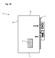
- the system On the figure 3E , the system is shown attached to the outside of the electrical cabinet 1.
- this cooling system 3 comprises a support 30 for supporting the elements necessary for cooling.
- the system also comprises a ventilation module 31 comprising an air inlet 310 intended to communicate with the internal space of the cabinet, a fan 311 for sucking air through the air inlet and an outlet of air 312.
- the system comprises a condenser module 32 comprising an air inlet 320 communicating with the air outlet 312 of the ventilation module 31, an air outlet 321 for injecting the cooled air towards the interior of the electrical cabinet 1 and a drain 322 of the water generated by the cooling of the air by a cooling module.
- the ventilation module 31 and the condenser module 32 are both fixed on the support 30.
- This condenser module 32 comprises a first outer casing 323 comprising an attachment plane by which it is fixed on the support 30 and a second casing 324 housed inside the first casing 323 and in which a cooling module 325 is placed.
- type of cooling module 324 is well known and has a structure in which circulates a Refrigerant. This structure can be in the form of coils, with parallel plates, ...
- the second housing 324 has the particularity of being inclined at a certain angle inside the first housing 323 relative to the plane of attachment of the first housing on the support 30. Whatever the location of the system 3 on the cabinet 1 and the orientation of the condenser module 32, the inclination of the second housing 324 allows the collection and flow of water generated by the cooling of the air.
- the air inlet 320 of the condenser module 32 communicates with the internal space of the second housing 324 in order to bring the air sucked by the ventilation module 31 onto the cooling module 325.
- the air outlet 321 of the module condenser 32 is arranged between the internal space of the second housing 324 and the internal space of the electrical cabinet 1.
- the air outlet 321 is offset relative to the edge of the second housing 324 to ensure that the condensate is not expelled by the air outlet 321 when the system is arranged vertically.
- the second housing 324 has two orifices 326 positioned in front of the air inlet or outlet sections for the discharge of the condensate.
- the air cooled by the cooling module 325 is thus reinjected into the electrical cabinet 1.
- the water generated by the passage of the air on the cooling module 325 flows inside the second casing 324 of the condenser module 32 and is discharged from the condenser module 32 via the evacuation duct 322.
- 30 integrates for its part a vent 300 of the water communicating with that of the condenser module 32.
- the system of the invention can thus be fixed on the electrical cabinet in different locations, without structural modification.
- the direction of air flow is indicated by the arrows.
- the system 3 is fixed on the internal face of a side wall 12 of the cabinet.
- the system 3 is fixed on the inner face of the lower wall 11 of the electrical cabinet.
- the system 3 is fixed on the opposite side to that of fixing the electrical devices on a support 4 positioned in the electrical cabinet.
- the system 3 is fixed on the inner face of the upper wall 10 of the electrical cabinet 1.
- the ventilation module 31 and the condenser module 32 are arranged to allow the evacuation of the water from the module condenser 32 and an additional outlet pipe 40 is added at the outlet of the condenser module 32.
Landscapes
- Engineering & Computer Science (AREA)
- Chemical & Material Sciences (AREA)
- Combustion & Propulsion (AREA)
- Mechanical Engineering (AREA)
- General Engineering & Computer Science (AREA)
- Power Engineering (AREA)
- Aviation & Aerospace Engineering (AREA)
- Physics & Mathematics (AREA)
- Thermal Sciences (AREA)
- Microelectronics & Electronic Packaging (AREA)
- Cooling Or The Like Of Electrical Apparatus (AREA)
Abstract
Description
- La présente invention se rapporte à un système de refroidissement destiné à être fixé sur une armoire électrique pour refroidir l'air présent dans ladite armoire.
- Une armoire électrique est destinée à recevoir un ou plusieurs appareils électriques. Certains de ces appareils électriques ont la particularité de chauffer et donc de réchauffer l'air environnant. Comme l'armoire électrique est fermée, il est nécessaire de prévoir un système de refroidissement de l'air présent dans l'armoire afin d'éviter toute surchauffe des appareils qui y sont installés.
- Selon l'emplacement de l'armoire électrique, le système de refroidissement peut être fixé sur l'armoire électrique à différents endroits. Il peut être fixé sur une face interne d'une paroi latérale de l'armoire électrique, sur la face interne de la paroi inférieure de l'armoire électrique, sur la face opposée à celle du support de fixation qui porte les appareils électriques ou entre le support de fixation des appareils électriques et la paroi supérieure de l'armoire électrique.
- Il est difficile de prévoir un système de refroidissement qui puisse s'adapter, sans modification, à ces différentes configurations de positionnement sur une armoire électrique.
- Le but de l'invention est de proposer un système de refroidissement d'air pour armoire électrique qui peut se fixer à différents emplacements sur l'armoire électrique, sans nécessiter de modifications.
- Ce but est atteint par Système de refroidissement pour armoire électrique dans laquelle sont placés un ou plusieurs appareils électriques, comportant :
- un support,
- un module de ventilation fixé sur ledit support et comprenant une entrée d'air agencée pour communiquer avec l'intérieur de l'armoire et une sortie d'air,
- un module condenseur fixé sur ledit support et comprenant un module de refroidissement, une entrée d'air communiquant avec la sortie d'air du module de ventilation pour recevoir l'air aspiré par le module de ventilation, une sortie d'air pour injecter l'air refroidi vers l'intérieur de l'armoire électrique et un conduit d'évacuation de l'eau générée par le refroidissement de l'air par le module de refroidissement,
- le système se caractérise en ce que :
- le module condenseur comporte un premier boîtier fixé sur le support, un deuxième boîtier logé à l'intérieur du premier boîtier et dans lequel débouchent l'entrée d'air et la sortie d'air du module condenseur, et un module de refroidissement logé dans le deuxième boîtier,
- ledit deuxième boîtier est agencé de manière inclinée à l'intérieur du premier boîtier de manière à permettre un écoulement de l'eau généré lors du passage de l'air sur le module de refroidissement quelle que soit la position du système sur l'armoire électrique.
- Selon une particularité, la sortie d'air est décalée par rapport à l'arête du deuxième boîtier du module condenseur.
- Selon une autre particularité, le deuxième boîtier comporte deux orifices agencés pour permettre une évacuation d'eau du deuxième boîtier.
- Selon une autre particularité, le conduit d'évacuation est intégré au support.
- Selon une autre particularité, le système comporte un conduit d'arrivée de fluide frigorigène intégré au support.
- D'autres caractéristiques et avantages vont apparaître dans la description détaillée qui suit faite en regard des dessins annexés dans lesquels :
- la
figure 1 représente, en vue de côté, le système de refroidissement de l'invention, - la
figure 2 représente le module d'évaporation du système de refroidissement de l'invention, - les
figures 3A à 3E représentent une armoire électrique accueillant, à différents emplacements, le système de refroidissement de l'invention. - De manière connue, une armoire électrique 1 est en règle générale de forme parallélépipédique et comporte une paroi inférieure 11, une paroi supérieure 10 et plusieurs parois latérales 12, l'une des parois latérales formant la porte de l'armoire électrique.
- Une armoire électrique est destinée à accueillir un ou plusieurs appareils électriques 2, par exemple de type disjoncteur, contacteur, variateur de vitesse, automate programmable,... En fonctionnement, certains de ces appareils électriques 2 génèrent de la chaleur. Comme l'armoire électrique 1 est fermée, il est nécessaire d'y adjoindre un système de refroidissement 3 en vue de refroidir l'air présent dans l'armoire électrique 1 et éviter ainsi toute surchauffe des appareils électriques 2 qui y sont installés.
- L'invention consiste en un système de refroidissement 3 venant se fixer sur une paroi de l'armoire électrique 1. Le système peut se fixer à l'intérieur ou à l'extérieur de l'armoire électrique. Sur les
figures 3A à 3D , le système est montré fixé à l'intérieur de l'armoire électrique 1. Sur lafigure 3E , le système est montré fixé à l'extérieur de l'armoire électrique 1. - En référence à la
figure 1 , ce système de refroidissement 3 comporte un support 30 destiné à supporter les éléments nécessaires au refroidissement. - Le système comporte également un module de ventilation 31 comprenant une entrée d'air 310 destinée à communiquer avec l'espace interne de l'armoire, un ventilateur 311 pour aspirer l'air à travers l'entrée d'air et une sortie d'air 312.
- Le système comporte un module condenseur 32 comprenant une entrée d'air 320 communiquant avec la sortie d'air 312 du module de ventilation 31, une sortie d'air 321 pour injecter l'air refroidi vers l'intérieur de l'armoire électrique 1 et un conduit d'évacuation 322 de l'eau générée par le refroidissement de l'air par un module de refroidissement.
- Le module de ventilation 31 et le module condenseur 32 sont tous les deux fixés sur le support 30.
- L'une des particularités du système de l'invention se situe au niveau du module condenseur 32, tel qu'il est représenté sur la
figure 2 . Ce module condenseur 32 comporte un premier boîtier externe 323 comprenant un plan de fixation par lequel il est fixé sur le support 30 et un deuxième boîtier 324 logé à l'intérieur du premier boîtier 323 et dans lequel est placé un module de refroidissement 325. Ce type de module de refroidissement 324 est bien connu et comporte une structure dans laquelle circule un fluide frigorigène. Cette structure peut être en forme de serpentins, à plaques parallèles,... - Le deuxième boîtier 324 présente la particularité d'être incliné d'un certain angle à l'intérieur du premier boîtier 323 par rapport au plan de fixation du premier boîtier sur le support 30. Quel que soit l'emplacement du système 3 sur l'armoire 1 et l'orientation du module condenseur 32, l'inclinaison du deuxième boîtier 324 permet la collecte et un écoulement de l'eau générée par le refroidissement de l'air.
- L'entrée d'air 320 du module condenseur 32 communique avec l'espace interne du deuxième boîtier 324 afin d'amener l'air aspiré par le module de ventilation 31 sur le module de refroidissement 325. La sortie d'air 321 du module condenseur 32 est agencée entre l'espace interne du deuxième boîtier 324 et l'espace interne de l'armoire électrique 1. La sortie d'air 321 est décalée par rapport à l'arête du deuxième boitier 324 pour faire en sorte que le condensat ne soit pas expulsé par la sortie d'air 321 lorsque le système est disposé verticalement.
- Le deuxième boitier 324 possède deux orifices 326 positionnés devant les sections d'entrée ou de sortie de l'air pour l'évacuation du condensat.
- L'air refroidi par le module de refroidissement 325 est ainsi réinjecté dans l'armoire électrique 1.
- L'eau générée par le passage de l'air sur le module de refroidissement 325 s'écoule à l'intérieur du deuxième boîtier 324 du module condenseur 32 et est évacuée hors du module condenseur 32 par le conduit d'évacuation 322. Le support 30 intègre pour sa part un conduit d'évacuation 300 de l'eau communiquant avec celui du module condenseur 32.
- Le support 30 intègre également un conduit d'arrivée 301 de fluide frigorigène communiquant avec le module de refroidissement 325.
- En référence aux
figures 3A à 3C , le système de l'invention peut ainsi être fixé sur l'armoire électrique en différents emplacements, sans modification structurelle. Sur ces figures, le sens de circulation de l'air est indiqué par les flèches. - Sur la
figure 3A , le système 3 est fixé sur la face interne d'une paroi latérale 12 de l'armoire. - Sur la
figure 3B , le système 3 est fixé sur la face interne de la paroi inférieure 11 de l'armoire électrique. - Sur la
figure 3C , le système 3 est fixé sur la face opposée à celle de fixation des appareils électriques sur un support 4 positionné dans l'armoire électrique. - Sur la
figure 3D , le système 3 est fixé sur la face interne de la paroi supérieure 10 de l'armoire électrique 1. Dans cette situation, le module de ventilation 31 et le module condenseur 32 sont arrangés pour permettre l'évacuation de l'eau issue du module condenseur 32 et un tuyau d'évacuation 40 supplémentaire est ajouté en sortie du module condenseur 32. - Sur la
figure 3E , le système est fixé sur la face externe d'une paroi latérale 12 de l'armoire électrique. On voit que l'agencement est identique aux agencements précédents. Dans cette configuration, il est cependant nécessaire de prévoir une ouverture à travers le support pour aspirer l'air dans l'armoire et le réinjecter dans celle-ci.
Claims (5)
- Système de refroidissement (3) pour armoire électrique (1) dans laquelle sont placés un ou plusieurs appareils électriques, ledit système comportant :- un support (30),- un module de ventilation (31) fixé sur ledit support et comprenant une entrée d'air (310) agencée pour communiquer avec l'intérieur de l'armoire et une sortie d'air (312),- un module condenseur (32) fixé sur ledit support et comprenant un module de refroidissement (325), une entrée d'air (320) communiquant avec la sortie d'air (312) du module de ventilation (31) pour recevoir l'air aspiré par le module de ventilation, une sortie d'air (321) pour injecter l'air refroidi vers l'intérieur de l'armoire électrique et un conduit d'évacuation (300) de l'eau générée par le refroidissement de l'air par le module de refroidissement,- caractérisé en ce que :- le module condenseur comporte un premier boîtier (323) fixé sur le support (30), un deuxième boîtier (324) logé à l'intérieur du premier boîtier (323) et dans lequel débouchent l'entrée d'air et la sortie d'air du module condenseur (32), et un module de refroidissement (325) logé dans le deuxième boîtier,- ledit deuxième boîtier (324) est agencé de manière inclinée à l'intérieur du premier boîtier (323) de manière à permettre un écoulement de l'eau générée lors du passage de l'air sur le module de refroidissement (325) quelle que soit la position du système sur l'armoire électrique (1).
- Système selon la revendication 1, caractérisé en ce que la sortie d'air (321) est décalée par rapport à l'arête du deuxième boîtier (324) du module condenseur (32).
- Système selon la revendication 1 ou 2, caractérisé en ce que le deuxième boîtier (324) comporte deux orifices (326) agencés pour permettre une évacuation d'eau du deuxième boîtier (324).
- Système selon l'une des revendications 1 à 3, caractérisé en ce que le conduit d'évacuation (300) est intégré au support (30).
- Système selon l'une des revendications 1 à 4, caractérisé en ce qu'il comporte un conduit d'arrivée (301) de fluide frigorigène intégré au support (30).
Applications Claiming Priority (1)
| Application Number | Priority Date | Filing Date | Title |
|---|---|---|---|
| FR1459166A FR3026472A1 (fr) | 2014-09-29 | 2014-09-29 | Systeme de refroidissement pour armoire electrique |
Publications (2)
| Publication Number | Publication Date |
|---|---|
| EP3002521A1 true EP3002521A1 (fr) | 2016-04-06 |
| EP3002521B1 EP3002521B1 (fr) | 2019-11-20 |
Family
ID=52345276
Family Applications (1)
| Application Number | Title | Priority Date | Filing Date |
|---|---|---|---|
| EP15184890.0A Active EP3002521B1 (fr) | 2014-09-29 | 2015-09-11 | Système de refroidissement pour armoire électrique |
Country Status (3)
| Country | Link |
|---|---|
| EP (1) | EP3002521B1 (fr) |
| ES (1) | ES2768684T3 (fr) |
| FR (1) | FR3026472A1 (fr) |
Cited By (2)
| Publication number | Priority date | Publication date | Assignee | Title |
|---|---|---|---|---|
| FR3074568A1 (fr) * | 2017-12-05 | 2019-06-07 | Astato | Caisson de ventilation d'une chicane en amont |
| CN111442392A (zh) * | 2019-01-17 | 2020-07-24 | 青岛海尔空调器有限总公司 | 壁挂式空调器室内机 |
Families Citing this family (1)
| Publication number | Priority date | Publication date | Assignee | Title |
|---|---|---|---|---|
| GB2591261B (en) * | 2020-01-22 | 2022-01-19 | Shiva Air Conditioning Ltd | A heat exchanger core |
Citations (3)
| Publication number | Priority date | Publication date | Assignee | Title |
|---|---|---|---|---|
| US5199276A (en) * | 1991-11-12 | 1993-04-06 | Sullivan John T | Fan coil unit with novel removable condensate pan |
| US20070051007A1 (en) * | 2005-09-08 | 2007-03-08 | Bridgewater, Inc. | Heat exchanger assembly with air mover |
| DE102010042948A1 (de) * | 2010-10-26 | 2012-04-26 | Blumartin Gmbh | Dezentrale Raumlüftungsvorrichtung mit Wärmerückgewinnung und Heizungsanschluß |
-
2014
- 2014-09-29 FR FR1459166A patent/FR3026472A1/fr not_active Withdrawn
-
2015
- 2015-09-11 ES ES15184890T patent/ES2768684T3/es active Active
- 2015-09-11 EP EP15184890.0A patent/EP3002521B1/fr active Active
Patent Citations (3)
| Publication number | Priority date | Publication date | Assignee | Title |
|---|---|---|---|---|
| US5199276A (en) * | 1991-11-12 | 1993-04-06 | Sullivan John T | Fan coil unit with novel removable condensate pan |
| US20070051007A1 (en) * | 2005-09-08 | 2007-03-08 | Bridgewater, Inc. | Heat exchanger assembly with air mover |
| DE102010042948A1 (de) * | 2010-10-26 | 2012-04-26 | Blumartin Gmbh | Dezentrale Raumlüftungsvorrichtung mit Wärmerückgewinnung und Heizungsanschluß |
Cited By (2)
| Publication number | Priority date | Publication date | Assignee | Title |
|---|---|---|---|---|
| FR3074568A1 (fr) * | 2017-12-05 | 2019-06-07 | Astato | Caisson de ventilation d'une chicane en amont |
| CN111442392A (zh) * | 2019-01-17 | 2020-07-24 | 青岛海尔空调器有限总公司 | 壁挂式空调器室内机 |
Also Published As
| Publication number | Publication date |
|---|---|
| ES2768684T3 (es) | 2020-06-23 |
| FR3026472A1 (fr) | 2016-04-01 |
| EP3002521B1 (fr) | 2019-11-20 |
Similar Documents
| Publication | Publication Date | Title |
|---|---|---|
| EP2789220B1 (fr) | Armoire electrique a dissipation thermique amelioree | |
| EP2098105B1 (fr) | Boitier d'appareillage electronique a refroidissement par ventilation naturelle et forcee | |
| EP3002521B1 (fr) | Système de refroidissement pour armoire électrique | |
| JP6051036B2 (ja) | 循環冷却加熱装置 | |
| FR2971093A1 (fr) | Batterie thermiquement regulee ou refroidie et vehicule equipe d'une telle batterie | |
| FR2480422A1 (fr) | Appareil d'echange de chaleur et support interne de celui-ci | |
| CN111351285B (zh) | 卧式冷柜 | |
| FR2991438A1 (fr) | Bac a condensats et appareil de traitement d'air muni d'un tel bac | |
| EP3733956B1 (fr) | Appareil electromenager a vapeur | |
| FR3036233A1 (fr) | Systeme de dissipation thermique pour enveloppe electrique | |
| FR2493667A1 (fr) | Dispositif de refroidissement pour installation contenant des equipements electroniques ou de telecommunications | |
| JP6694231B2 (ja) | 加熱調理器 | |
| FR3060225A1 (fr) | Dispositif de ventilation de l'air a l'interieur d'une enveloppe destinee a loger des appareils electriques modulaires, et enveloppe comportant un tel dispositif | |
| FR3144549A1 (fr) | Système de gestion thermique pour véhicule | |
| FR3151083A1 (fr) | Assemblage comportant un échangeur de chaleur | |
| JP6075405B2 (ja) | 電気ポット | |
| EP3109120B1 (fr) | Coffre de traction d'un véhicule ferroviaire et véhicule ferroviaire associé | |
| FR3000787A1 (fr) | Chauffe-eau thermodynamique | |
| FR3094566A1 (fr) | Dispositif de ventilation pour enceinte acoustique, enceinte acoustique et procédé correspondant | |
| EP1889527B1 (fr) | Systeme de ventilation | |
| EP2532949B1 (fr) | Dispositif d'éclairage et/ou de signalisation à radiateur et dissipateur intégrés | |
| CN212842971U (zh) | 微电子元器件高真空热板烘烤除气炉 | |
| FR2876781A1 (fr) | Four de cuisson comportant un dispositif de ventilation des organes de commande | |
| JP6741486B2 (ja) | 水検知装置および加熱調理器 | |
| FR3012540A1 (fr) | Dispositif de refroidissement du moteur d'un ventilateur |
Legal Events
| Date | Code | Title | Description |
|---|---|---|---|
| PUAI | Public reference made under article 153(3) epc to a published international application that has entered the european phase |
Free format text: ORIGINAL CODE: 0009012 |
|
| AK | Designated contracting states |
Kind code of ref document: A1 Designated state(s): AL AT BE BG CH CY CZ DE DK EE ES FI FR GB GR HR HU IE IS IT LI LT LU LV MC MK MT NL NO PL PT RO RS SE SI SK SM TR |
|
| AX | Request for extension of the european patent |
Extension state: BA ME |
|
| 17P | Request for examination filed |
Effective date: 20160414 |
|
| RBV | Designated contracting states (corrected) |
Designated state(s): AL AT BE BG CH CY CZ DE DK EE ES FI FR GB GR HR HU IE IS IT LI LT LU LV MC MK MT NL NO PL PT RO RS SE SI SK SM TR |
|
| STAA | Information on the status of an ep patent application or granted ep patent |
Free format text: STATUS: REQUEST FOR EXAMINATION WAS MADE |
|
| STAA | Information on the status of an ep patent application or granted ep patent |
Free format text: STATUS: EXAMINATION IS IN PROGRESS |
|
| 17Q | First examination report despatched |
Effective date: 20190429 |
|
| GRAP | Despatch of communication of intention to grant a patent |
Free format text: ORIGINAL CODE: EPIDOSNIGR1 |
|
| STAA | Information on the status of an ep patent application or granted ep patent |
Free format text: STATUS: GRANT OF PATENT IS INTENDED |
|
| RIC1 | Information provided on ipc code assigned before grant |
Ipc: F24F 1/0057 20190101ALI20190731BHEP Ipc: F24F 1/027 20190101ALI20190731BHEP Ipc: H05K 7/20 20060101ALI20190731BHEP Ipc: H02B 1/56 20060101ALI20190731BHEP Ipc: F24F 1/02 20190101AFI20190731BHEP |
|
| INTG | Intention to grant announced |
Effective date: 20190829 |
|
| GRAS | Grant fee paid |
Free format text: ORIGINAL CODE: EPIDOSNIGR3 |
|
| GRAA | (expected) grant |
Free format text: ORIGINAL CODE: 0009210 |
|
| STAA | Information on the status of an ep patent application or granted ep patent |
Free format text: STATUS: THE PATENT HAS BEEN GRANTED |
|
| AK | Designated contracting states |
Kind code of ref document: B1 Designated state(s): AL AT BE BG CH CY CZ DE DK EE ES FI FR GB GR HR HU IE IS IT LI LT LU LV MC MK MT NL NO PL PT RO RS SE SI SK SM TR |
|
| REG | Reference to a national code |
Ref country code: GB Ref legal event code: FG4D Free format text: NOT ENGLISH |
|
| REG | Reference to a national code |
Ref country code: CH Ref legal event code: EP |
|
| REG | Reference to a national code |
Ref country code: DE Ref legal event code: R096 Ref document number: 602015041952 Country of ref document: DE |
|
| REG | Reference to a national code |
Ref country code: IE Ref legal event code: FG4D Free format text: LANGUAGE OF EP DOCUMENT: FRENCH |
|
| REG | Reference to a national code |
Ref country code: AT Ref legal event code: REF Ref document number: 1204623 Country of ref document: AT Kind code of ref document: T Effective date: 20191215 |
|
| REG | Reference to a national code |
Ref country code: NL Ref legal event code: MP Effective date: 20191120 |
|
| REG | Reference to a national code |
Ref country code: LT Ref legal event code: MG4D |
|
| PG25 | Lapsed in a contracting state [announced via postgrant information from national office to epo] |
Ref country code: NL Free format text: LAPSE BECAUSE OF FAILURE TO SUBMIT A TRANSLATION OF THE DESCRIPTION OR TO PAY THE FEE WITHIN THE PRESCRIBED TIME-LIMIT Effective date: 20191120 Ref country code: LT Free format text: LAPSE BECAUSE OF FAILURE TO SUBMIT A TRANSLATION OF THE DESCRIPTION OR TO PAY THE FEE WITHIN THE PRESCRIBED TIME-LIMIT Effective date: 20191120 Ref country code: BG Free format text: LAPSE BECAUSE OF FAILURE TO SUBMIT A TRANSLATION OF THE DESCRIPTION OR TO PAY THE FEE WITHIN THE PRESCRIBED TIME-LIMIT Effective date: 20200220 Ref country code: FI Free format text: LAPSE BECAUSE OF FAILURE TO SUBMIT A TRANSLATION OF THE DESCRIPTION OR TO PAY THE FEE WITHIN THE PRESCRIBED TIME-LIMIT Effective date: 20191120 Ref country code: NO Free format text: LAPSE BECAUSE OF FAILURE TO SUBMIT A TRANSLATION OF THE DESCRIPTION OR TO PAY THE FEE WITHIN THE PRESCRIBED TIME-LIMIT Effective date: 20200220 Ref country code: GR Free format text: LAPSE BECAUSE OF FAILURE TO SUBMIT A TRANSLATION OF THE DESCRIPTION OR TO PAY THE FEE WITHIN THE PRESCRIBED TIME-LIMIT Effective date: 20200221 Ref country code: SE Free format text: LAPSE BECAUSE OF FAILURE TO SUBMIT A TRANSLATION OF THE DESCRIPTION OR TO PAY THE FEE WITHIN THE PRESCRIBED TIME-LIMIT Effective date: 20191120 Ref country code: LV Free format text: LAPSE BECAUSE OF FAILURE TO SUBMIT A TRANSLATION OF THE DESCRIPTION OR TO PAY THE FEE WITHIN THE PRESCRIBED TIME-LIMIT Effective date: 20191120 |
|
| PG25 | Lapsed in a contracting state [announced via postgrant information from national office to epo] |
Ref country code: HR Free format text: LAPSE BECAUSE OF FAILURE TO SUBMIT A TRANSLATION OF THE DESCRIPTION OR TO PAY THE FEE WITHIN THE PRESCRIBED TIME-LIMIT Effective date: 20191120 Ref country code: RS Free format text: LAPSE BECAUSE OF FAILURE TO SUBMIT A TRANSLATION OF THE DESCRIPTION OR TO PAY THE FEE WITHIN THE PRESCRIBED TIME-LIMIT Effective date: 20191120 Ref country code: IS Free format text: LAPSE BECAUSE OF FAILURE TO SUBMIT A TRANSLATION OF THE DESCRIPTION OR TO PAY THE FEE WITHIN THE PRESCRIBED TIME-LIMIT Effective date: 20200320 |
|
| REG | Reference to a national code |
Ref country code: ES Ref legal event code: FG2A Ref document number: 2768684 Country of ref document: ES Kind code of ref document: T3 Effective date: 20200623 |
|
| PG25 | Lapsed in a contracting state [announced via postgrant information from national office to epo] |
Ref country code: AL Free format text: LAPSE BECAUSE OF FAILURE TO SUBMIT A TRANSLATION OF THE DESCRIPTION OR TO PAY THE FEE WITHIN THE PRESCRIBED TIME-LIMIT Effective date: 20191120 |
|
| PG25 | Lapsed in a contracting state [announced via postgrant information from national office to epo] |
Ref country code: RO Free format text: LAPSE BECAUSE OF FAILURE TO SUBMIT A TRANSLATION OF THE DESCRIPTION OR TO PAY THE FEE WITHIN THE PRESCRIBED TIME-LIMIT Effective date: 20191120 Ref country code: DK Free format text: LAPSE BECAUSE OF FAILURE TO SUBMIT A TRANSLATION OF THE DESCRIPTION OR TO PAY THE FEE WITHIN THE PRESCRIBED TIME-LIMIT Effective date: 20191120 Ref country code: CZ Free format text: LAPSE BECAUSE OF FAILURE TO SUBMIT A TRANSLATION OF THE DESCRIPTION OR TO PAY THE FEE WITHIN THE PRESCRIBED TIME-LIMIT Effective date: 20191120 Ref country code: PT Free format text: LAPSE BECAUSE OF FAILURE TO SUBMIT A TRANSLATION OF THE DESCRIPTION OR TO PAY THE FEE WITHIN THE PRESCRIBED TIME-LIMIT Effective date: 20200412 Ref country code: EE Free format text: LAPSE BECAUSE OF FAILURE TO SUBMIT A TRANSLATION OF THE DESCRIPTION OR TO PAY THE FEE WITHIN THE PRESCRIBED TIME-LIMIT Effective date: 20191120 |
|
| REG | Reference to a national code |
Ref country code: AT Ref legal event code: MK05 Ref document number: 1204623 Country of ref document: AT Kind code of ref document: T Effective date: 20191120 |
|
| REG | Reference to a national code |
Ref country code: DE Ref legal event code: R097 Ref document number: 602015041952 Country of ref document: DE |
|
| PG25 | Lapsed in a contracting state [announced via postgrant information from national office to epo] |
Ref country code: SM Free format text: LAPSE BECAUSE OF FAILURE TO SUBMIT A TRANSLATION OF THE DESCRIPTION OR TO PAY THE FEE WITHIN THE PRESCRIBED TIME-LIMIT Effective date: 20191120 Ref country code: SK Free format text: LAPSE BECAUSE OF FAILURE TO SUBMIT A TRANSLATION OF THE DESCRIPTION OR TO PAY THE FEE WITHIN THE PRESCRIBED TIME-LIMIT Effective date: 20191120 |
|
| PLBE | No opposition filed within time limit |
Free format text: ORIGINAL CODE: 0009261 |
|
| STAA | Information on the status of an ep patent application or granted ep patent |
Free format text: STATUS: NO OPPOSITION FILED WITHIN TIME LIMIT |
|
| 26N | No opposition filed |
Effective date: 20200821 |
|
| PG25 | Lapsed in a contracting state [announced via postgrant information from national office to epo] |
Ref country code: SI Free format text: LAPSE BECAUSE OF FAILURE TO SUBMIT A TRANSLATION OF THE DESCRIPTION OR TO PAY THE FEE WITHIN THE PRESCRIBED TIME-LIMIT Effective date: 20191120 Ref country code: PL Free format text: LAPSE BECAUSE OF FAILURE TO SUBMIT A TRANSLATION OF THE DESCRIPTION OR TO PAY THE FEE WITHIN THE PRESCRIBED TIME-LIMIT Effective date: 20191120 Ref country code: AT Free format text: LAPSE BECAUSE OF FAILURE TO SUBMIT A TRANSLATION OF THE DESCRIPTION OR TO PAY THE FEE WITHIN THE PRESCRIBED TIME-LIMIT Effective date: 20191120 |
|
| REG | Reference to a national code |
Ref country code: DE Ref legal event code: R119 Ref document number: 602015041952 Country of ref document: DE |
|
| PG25 | Lapsed in a contracting state [announced via postgrant information from national office to epo] |
Ref country code: MC Free format text: LAPSE BECAUSE OF FAILURE TO SUBMIT A TRANSLATION OF THE DESCRIPTION OR TO PAY THE FEE WITHIN THE PRESCRIBED TIME-LIMIT Effective date: 20191120 |
|
| REG | Reference to a national code |
Ref country code: CH Ref legal event code: PL |
|
| GBPC | Gb: european patent ceased through non-payment of renewal fee |
Effective date: 20200911 |
|
| REG | Reference to a national code |
Ref country code: BE Ref legal event code: MM Effective date: 20200930 |
|
| PG25 | Lapsed in a contracting state [announced via postgrant information from national office to epo] |
Ref country code: LU Free format text: LAPSE BECAUSE OF NON-PAYMENT OF DUE FEES Effective date: 20200911 |
|
| PG25 | Lapsed in a contracting state [announced via postgrant information from national office to epo] |
Ref country code: DE Free format text: LAPSE BECAUSE OF NON-PAYMENT OF DUE FEES Effective date: 20210401 |
|
| PG25 | Lapsed in a contracting state [announced via postgrant information from national office to epo] |
Ref country code: BE Free format text: LAPSE BECAUSE OF NON-PAYMENT OF DUE FEES Effective date: 20200930 Ref country code: CH Free format text: LAPSE BECAUSE OF NON-PAYMENT OF DUE FEES Effective date: 20200930 Ref country code: LI Free format text: LAPSE BECAUSE OF NON-PAYMENT OF DUE FEES Effective date: 20200930 Ref country code: IE Free format text: LAPSE BECAUSE OF NON-PAYMENT OF DUE FEES Effective date: 20200911 Ref country code: GB Free format text: LAPSE BECAUSE OF NON-PAYMENT OF DUE FEES Effective date: 20200911 |
|
| PG25 | Lapsed in a contracting state [announced via postgrant information from national office to epo] |
Ref country code: TR Free format text: LAPSE BECAUSE OF FAILURE TO SUBMIT A TRANSLATION OF THE DESCRIPTION OR TO PAY THE FEE WITHIN THE PRESCRIBED TIME-LIMIT Effective date: 20191120 Ref country code: MT Free format text: LAPSE BECAUSE OF FAILURE TO SUBMIT A TRANSLATION OF THE DESCRIPTION OR TO PAY THE FEE WITHIN THE PRESCRIBED TIME-LIMIT Effective date: 20191120 Ref country code: CY Free format text: LAPSE BECAUSE OF FAILURE TO SUBMIT A TRANSLATION OF THE DESCRIPTION OR TO PAY THE FEE WITHIN THE PRESCRIBED TIME-LIMIT Effective date: 20191120 |
|
| PG25 | Lapsed in a contracting state [announced via postgrant information from national office to epo] |
Ref country code: MK Free format text: LAPSE BECAUSE OF FAILURE TO SUBMIT A TRANSLATION OF THE DESCRIPTION OR TO PAY THE FEE WITHIN THE PRESCRIBED TIME-LIMIT Effective date: 20191120 |
|
| PGFP | Annual fee paid to national office [announced via postgrant information from national office to epo] |
Ref country code: IT Payment date: 20250922 Year of fee payment: 11 |
|
| PGFP | Annual fee paid to national office [announced via postgrant information from national office to epo] |
Ref country code: FR Payment date: 20250925 Year of fee payment: 11 |
|
| PGFP | Annual fee paid to national office [announced via postgrant information from national office to epo] |
Ref country code: ES Payment date: 20251015 Year of fee payment: 11 |