EP3002467B1 - Self-tapping screw for soft metals - Google Patents
Self-tapping screw for soft metals Download PDFInfo
- Publication number
- EP3002467B1 EP3002467B1 EP15810792.0A EP15810792A EP3002467B1 EP 3002467 B1 EP3002467 B1 EP 3002467B1 EP 15810792 A EP15810792 A EP 15810792A EP 3002467 B1 EP3002467 B1 EP 3002467B1
- Authority
- EP
- European Patent Office
- Prior art keywords
- diameter part
- screw
- self
- tapping screw
- tapping
- Prior art date
- Legal status (The legal status is an assumption and is not a legal conclusion. Google has not performed a legal analysis and makes no representation as to the accuracy of the status listed.)
- Active
Links
- 238000010079 rubber tapping Methods 0.000 title claims description 42
- 229910052751 metal Inorganic materials 0.000 title claims description 25
- 239000002184 metal Substances 0.000 title claims description 25
- 150000002739 metals Chemical class 0.000 title claims description 19
- 238000003780 insertion Methods 0.000 claims description 2
- 230000037431 insertion Effects 0.000 claims description 2
- 239000000843 powder Substances 0.000 description 17
- 229910000838 Al alloy Inorganic materials 0.000 description 7
- 229910000861 Mg alloy Inorganic materials 0.000 description 6
- 229910000831 Steel Inorganic materials 0.000 description 4
- 230000013011 mating Effects 0.000 description 4
- 239000010959 steel Substances 0.000 description 4
- 238000010586 diagram Methods 0.000 description 2
- 238000004519 manufacturing process Methods 0.000 description 2
- 238000000034 method Methods 0.000 description 2
- 230000003247 decreasing effect Effects 0.000 description 1
- 230000000694 effects Effects 0.000 description 1
Images

Classifications
-
- F—MECHANICAL ENGINEERING; LIGHTING; HEATING; WEAPONS; BLASTING
- F16—ENGINEERING ELEMENTS AND UNITS; GENERAL MEASURES FOR PRODUCING AND MAINTAINING EFFECTIVE FUNCTIONING OF MACHINES OR INSTALLATIONS; THERMAL INSULATION IN GENERAL
- F16B—DEVICES FOR FASTENING OR SECURING CONSTRUCTIONAL ELEMENTS OR MACHINE PARTS TOGETHER, e.g. NAILS, BOLTS, CIRCLIPS, CLAMPS, CLIPS OR WEDGES; JOINTS OR JOINTING
- F16B25/00—Screws that cut thread in the body into which they are screwed, e.g. wood screws
- F16B25/001—Screws that cut thread in the body into which they are screwed, e.g. wood screws characterised by the material of the body into which the screw is screwed
- F16B25/0021—Screws that cut thread in the body into which they are screwed, e.g. wood screws characterised by the material of the body into which the screw is screwed the material being metal, e.g. sheet-metal or aluminium
-
- F—MECHANICAL ENGINEERING; LIGHTING; HEATING; WEAPONS; BLASTING
- F16—ENGINEERING ELEMENTS AND UNITS; GENERAL MEASURES FOR PRODUCING AND MAINTAINING EFFECTIVE FUNCTIONING OF MACHINES OR INSTALLATIONS; THERMAL INSULATION IN GENERAL
- F16B—DEVICES FOR FASTENING OR SECURING CONSTRUCTIONAL ELEMENTS OR MACHINE PARTS TOGETHER, e.g. NAILS, BOLTS, CIRCLIPS, CLAMPS, CLIPS OR WEDGES; JOINTS OR JOINTING
- F16B25/00—Screws that cut thread in the body into which they are screwed, e.g. wood screws
- F16B25/0036—Screws that cut thread in the body into which they are screwed, e.g. wood screws characterised by geometric details of the screw
- F16B25/0042—Screws that cut thread in the body into which they are screwed, e.g. wood screws characterised by geometric details of the screw characterised by the geometry of the thread, the thread being a ridge wrapped around the shaft of the screw
- F16B25/0052—Screws that cut thread in the body into which they are screwed, e.g. wood screws characterised by geometric details of the screw characterised by the geometry of the thread, the thread being a ridge wrapped around the shaft of the screw the ridge having indentations, notches or the like in order to improve the cutting behaviour
-
- F—MECHANICAL ENGINEERING; LIGHTING; HEATING; WEAPONS; BLASTING
- F16—ENGINEERING ELEMENTS AND UNITS; GENERAL MEASURES FOR PRODUCING AND MAINTAINING EFFECTIVE FUNCTIONING OF MACHINES OR INSTALLATIONS; THERMAL INSULATION IN GENERAL
- F16B—DEVICES FOR FASTENING OR SECURING CONSTRUCTIONAL ELEMENTS OR MACHINE PARTS TOGETHER, e.g. NAILS, BOLTS, CIRCLIPS, CLAMPS, CLIPS OR WEDGES; JOINTS OR JOINTING
- F16B25/00—Screws that cut thread in the body into which they are screwed, e.g. wood screws
- F16B25/10—Screws performing an additional function to thread-forming, e.g. drill screws or self-piercing screws
- F16B25/103—Screws performing an additional function to thread-forming, e.g. drill screws or self-piercing screws by means of a drilling screw-point, i.e. with a cutting and material removing action
Definitions
- the present invention relates to a self-tapping screw for soft metals that is used for soft metals, such as aluminum alloys and magnesium alloys.
- a self-tapping screw is a screw that can be driven into a pilot hole formed in a mating member, so that it can be tightened while creating a female screw on the inner surface of a pilot hole.
- the self-tapping screw has been widely used because of its feature of requiring no tapping process in advance in the pilot hole.
- the self-tapping screw has been required to be capable of being driven by minimum possible initial driving torque.
- one commercially available self-tapping screw has a shaft with a polygonal cross section achieving a smaller contact area with the pilot hole as described in Patent Literature 1.
- the shaft of the self-tapping screw having a non-circular cross section has a male screw that does not mate with the female screw as the mating member evenly over the entire circumference even in the fully tightened state. More specifically, the male screw tightly mates with the female screw at the apexes of the polygon, and not at a portion between the apexes. All things considered, there has been a problem in that axial force in the tightened state is more likely to be reduced due to heat or the like, compared with standard screws having circular cross sections.
- US 2005/265805 discloses a looseness resisting screw with a thread area towards the leading end of the screw with a plurality of fractional lead parts with an outer thread diameter increasing from a start point, at which the thread height is equal to the thread root diameter, to an end point.
- a self-tapping screw includes a tapered smaller diameter part at an end of a shaft.
- the smaller diameter part being for insertion and driving into a pilot hole formed in a soft metal, in a driving direction, to form a female screw in the pilot hole.
- a continuous male screw with a constant pitch is formed in the shaft and the smaller diameter part.
- a thread ridge of the male screw of the smaller diameter part is provided with multiple sets of a largest diameter part and an increasing diameter part, the largest diameter part having a stepped part at a position on a trailing side of the largest diameter part in the driving direction, and wherein during driven turning of the screw, the increasing diameter part having a gradually increasing diameter from the stepped part to a next largest diameter part.
- the increasing diameter parts have a minimum diameter falling within a range of 30% to 80% of a thread ridge height of the male screw at the corresponding position. It is preferable that the multiple sets include three to eight sets.
- the thread angle of the male screw be 60°, which is the same as in standard screws, and more preferably 15° to 45°.
- the self-tapping screw for soft metals includes the shaft and the smaller diameter part the cross-sectional shape of which is circular like standard screws.
- the self-tapping screw therefore requires no intricate and expensive molds and can be manufactured at a low cost.
- the male screw tightly mates with the female screw along the entire circumference, and thus the axial force in the tightened state is maintained at a high level.
- the thread ridge of the male screw of the smaller diameter part is provided with multiple sets of the largest diameter part having the stepped part at the position on the trailing side of the largest diameter part during the driven turning of the screw and the increasing diameter part having a gradually increasing diameter from the stepped part to the next largest diameter part, and thus the inner surface of the pilot hole in a soft metal is plastically deformed by the increasing diameter part having a gradually increasing diameter and the following largest diameter part during the driven turning of the screw, whereby a female screw is created.
- the largest diameter part comes into contact with the inner surface of the pilot hole at only several areas, whereby the initial driving torque can be reduced.
- the self-tapping screw for soft metals according to the present invention does not have cutting edges on the front side in the driven turning direction unlike conventional screws.
- the amount of chip powder produced can be thus reduced even when soft metals, such as aluminum alloys and magnesium alloys, are employed. Chip powder can be discharged into or through a gap formed on the outer circumference of the increasing diameter part.
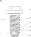
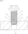
- FIG. 1 is a diagram illustrating an entire self-tapping screw for soft metals according to an embodiment, including a head 1, a shaft 2 having a circular cross section and a constant diameter, and a tapered smaller diameter part 3 at an end of the shaft 2.
- a continuous male screw with a constant pitch is formed as in conventional cases.
- the male screw of the shaft 2 has a complete thread with a thread ridge 4 having a constant diameter, whereas the male screw of the smaller diameter part 3 has a thread ridge 5 with a diameter gradually reducing toward the end.
- the self-tapping screw for soft metals of the present invention is not a screw having a non-circular cross section, and thus requires no intricate and expensive mold and can be manufactured at a low cost.
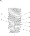
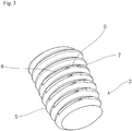
- FIG. 2 is an enlarged front view of the smaller diameter part 3 and FIG. 3 is a perspective view of the smaller diameter part 3.
- the thread ridge 5 of the male screw of the smaller diameter part 3 is provided with multiple sets of projecting and recessed parts achieving a tapping function.
- a largest diameter part 6 extends for a predetermined angle ⁇ in the circumferential direction.
- the largest diameter part 6 has the same diameter as the edge diameter (ridge diameter) of the thread ridge 5 at the corresponding position.
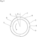
- FIG. 4 is a bottom view of the smaller diameter part 3 taken along a plane perpendicular to an axial line, and the head 1 is on the back side of the paper of FIG. 4 , and the driving direction of a right-hand screw is counterclockwise as shown indicated by an arrow.
- a stepped part 7 is formed at which the diameter is reduced substantially vertically. From the bottom of the stepped part 7, the diameter gradually increases toward the next largest diameter part 6 to form an increasing diameter part 8. Thus, a gap 9 is formed outside the increasing diameter part 8. Chip powder can be discharged into or through the gap 9.
- the minimum diameter of the stepped part 7 falls within a range of 30% to 80% of the thread ridge height of the male screw at the corresponding cross-sectional position. This range is defined because a value higher than 80% of the thread ridge height will result in lowered tapping capability and a value smaller than 30% will cause severe metal wear.
- the projecting and recessed parts, formed in the thread ridge 5 of the male screw of the smaller diameter part 3, for achieving the tapping function include the largest diameter part 6, the stepped part 7, and the increasing diameter part 8.
- the number of sets of projecting and recessed parts in an equal interval may be selected from a range between three to eight. This range is defined because two sets cannot ensure sufficient stability during the driving of the thread and nine or more sets define a substantially circular shape, resulting in a degraded tapping function.
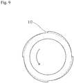
- FIG. 9 A conventional self-tapping screw for steel described in Patent Literature 2 is illustrated in FIG. 9 for a reference purpose.
- the conventional screw includes cutting edges 10 formed at the position on the leading side of the screw being driven to be turned.
- the cutting edges 10 are used for cutting the inner surface of a pilot hole formed in a steel member.
- the cutting edges 10 are however not suitable for soft metals, such as aluminum alloys and magnesium alloys, because the cutting edges 10 can excessively carve the inner surface of the pilot hole and produce a large amount of chip powder as described in an example below.
- the thus-configured self-tapping screw for soft metals having the configuration described above, is driven into a pilot hole 12 formed in a soft metal 11, such as an aluminum alloy or a magnesium alloy, to be used as shown in FIG. 5 .
- the largest diameter part 6 as a portion of the projecting and recessed parts formed in the smaller diameter part 3, deeply taps the inner circumference of the pilot hole 12 to cause plastic deformation. Then, the portion above the smaller diameter part 3 gradually taps. As a result, a female screw is created that has the thread bottom corresponding to the thread ridge 4 of the shaft 2.
- the inner surface of the pilot hole 12 is pushed open by the increasing diameter part 8 with a diameter gradually increasing from the bottom of the stepped part 7, so as not to produce a large amount of chip powder. Furthermore, chip powder that had to be inevitably produced is discharged through the gap 9 formed on the trailing side of the stepped part 7.
- positions where the largest diameter part 6 taps the inner circumference of the pilot hole 12 are not along the entire circumference of the pilot hole but limited to four areas in the present embodiment, so that the required initial driving torque can be small.
- final tightening is achieved by the complete screw of the shaft 2, and thus the axial force in the tightened state that is the same as that of standard screws can be achieved.
- a self-tapping screw for soft metals having the structure described in the above-mentioned embodiment was compared with a self-tapping screw having a triangular cross section as described in Patent Literature 1 in terms of driving torque, fracture torque, and maximum axial force.
- the screw size used was JIS M6.
- Aluminum alloy plates with pilot holes having diameters of 5.2 to 5.8 mm were used for the test.
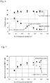
- FIG. 6 shows measured values of driving torque and fracture torque.
- the outlined circles and triangles represent the test results of self-tapping screws according to Patent Literature 1, whereas the black circles and triangles represent the test results of self-tapping screws according to the present invention. As shown in FIG. 6 , no significant difference was found between both types of screws.
- FIG. 7 shows the test results.
- the maximum axial force of self-tapping screws according to Patent Literature 1, represented by the outlined triangles decreased as the pilot hole diameter increased. This is because, as described above, the apexes serving as the only contact areas damage the threads that have been formed when axial force is produced, resulting in increased torque.
- Table 1 lists the results.
- the self-tapping screw having forward cutting edges as described in Patent Literature 2 produced a large amount of chip powder.
- the self-tapping screw having a triangular cross section as described in Patent Literature 1 produced a smaller amount of chip powder.
- the self-tapping screw according to the present invention produced a far smaller amount of chip powder and, in particular, produced only a negligible amount of chip powder during the fastening of the screw, which can cause a problem in practical use.
- Table 1 Pilot hole diameter Patent Literature 1 Patent Literature 2 Present Invention Loosening Fastening Loosening Fastening Loosening Fastening 5.33 mm 8 5 10 4 7 3 5.48 mm 7 1 9 3 7 1 5.63 mm 8 1 10 3 6 1
- the thread angle of the male screw formed in the shaft 2 and the smaller diameter part 3 was 60°, as in conventional cases.
- a thread angle ⁇ was 15° to 45° as illustrated in FIG. 8 . With this small thread angle ⁇ , the screw has a sharpened end that leads to smaller driving torque and a smaller amount of chip powder produced.
- the self-tapping screw for soft metals features low required driving torque, high maximum axial force, small axial force reduction due to heat or the like, and a low manufacturing cost, and also has distinctive advantages including the reduced amount of chip powder produced.
Description
- The present invention relates to a self-tapping screw for soft metals that is used for soft metals, such as aluminum alloys and magnesium alloys.
- A self-tapping screw is a screw that can be driven into a pilot hole formed in a mating member, so that it can be tightened while creating a female screw on the inner surface of a pilot hole. The self-tapping screw has been widely used because of its feature of requiring no tapping process in advance in the pilot hole.
- The self-tapping screw has been required to be capable of being driven by minimum possible initial driving torque. In this context, one commercially available self-tapping screw has a shaft with a polygonal cross section achieving a smaller contact area with the pilot hole as described in
Patent Literature 1. - Unfortunately, there has been a problem in that such a self-tapping screw having a non-circular cross section needs to be manufactured with an intricate and expensive mold, and thus requires a higher manufacturing cost than standard screws. In addition, the shaft of the self-tapping screw having a non-circular cross section has a male screw that does not mate with the female screw as the mating member evenly over the entire circumference even in the fully tightened state. More specifically, the male screw tightly mates with the female screw at the apexes of the polygon, and not at a portion between the apexes. All things considered, there has been a problem in that axial force in the tightened state is more likely to be reduced due to heat or the like, compared with standard screws having circular cross sections.
- Conventional self-tapping screws are supposed to be mated with a mating member made of steel, and thus have sharp cutting edges as described in
Patent Literature 2. Thus, when such a screw is driven into soft metals, such as aluminum alloys and magnesium alloys, a large amount of chip powder is produced due to excessive tapping. In particular, when the mating member is made of a magnesium alloy, chip powder produced might catch fire in a certain environment. -
US 2005/265805 discloses a looseness resisting screw with a thread area towards the leading end of the screw with a plurality of fractional lead parts with an outer thread diameter increasing from a start point, at which the thread height is equal to the thread root diameter, to an end point. -
- Patent Literature 1: Japanese Patent Application Publication No.
1999-247817 - Patent Literature 2: Japanese Patent No.
4219247 - In view of the foregoing, it is an object of the present invention to solve the disadvantages in related art and provide a self-tapping screw for soft metals that involves low initial driving torque, exhibits high axial force in the tightened state, requires no intricate and expensive molds and can be manufactured at a low cost, and with which the amount of chip powder produced is reduced.
- According to the present invention developed to solve the above-described disadvantages, a self-tapping screw includes a tapered smaller diameter part at an end of a shaft. The smaller diameter part being for insertion and driving into a pilot hole formed in a soft metal, in a driving direction, to form a female screw in the pilot hole. A continuous male screw with a constant pitch is formed in the shaft and the smaller diameter part. A thread ridge of the male screw of the smaller diameter part is provided with multiple sets of a largest diameter part and an increasing diameter part, the largest diameter part having a stepped part at a position on a trailing side of the largest diameter part in the driving direction, and wherein during driven turning of the screw, the increasing diameter part having a gradually increasing diameter from the stepped part to a next largest diameter part.
- The increasing diameter parts have a minimum diameter falling within a range of 30% to 80% of a thread ridge height of the male screw at the corresponding position. It is preferable that the multiple sets include three to eight sets.
- It is sufficient that the thread angle of the male screw be 60°, which is the same as in standard screws, and more preferably 15° to 45°.
- The self-tapping screw for soft metals according to the present invention includes the shaft and the smaller diameter part the cross-sectional shape of which is circular like standard screws. The self-tapping screw therefore requires no intricate and expensive molds and can be manufactured at a low cost. In addition, the male screw tightly mates with the female screw along the entire circumference, and thus the axial force in the tightened state is maintained at a high level. Furthermore, the thread ridge of the male screw of the smaller diameter part is provided with multiple sets of the largest diameter part having the stepped part at the position on the trailing side of the largest diameter part during the driven turning of the screw and the increasing diameter part having a gradually increasing diameter from the stepped part to the next largest diameter part, and thus the inner surface of the pilot hole in a soft metal is plastically deformed by the increasing diameter part having a gradually increasing diameter and the following largest diameter part during the driven turning of the screw, whereby a female screw is created. In this process, the largest diameter part comes into contact with the inner surface of the pilot hole at only several areas, whereby the initial driving torque can be reduced.
- The self-tapping screw for soft metals according to the present invention does not have cutting edges on the front side in the driven turning direction unlike conventional screws. The amount of chip powder produced can be thus reduced even when soft metals, such as aluminum alloys and magnesium alloys, are employed. Chip powder can be discharged into or through a gap formed on the outer circumference of the increasing diameter part.
-
-
FIG. 1 is a diagram illustrating an entire self-tapping screw for soft metals according to an embodiment. -
FIG. 2 is an enlarged front view of a smaller diameter part. -
FIG. 3 is an enlarged perspective view of the smaller diameter part. -
FIG. 4 is a bottom view of the smaller diameter part taken along a plane perpendicular to an axial line. -
FIG. 5 is a schematic for explaining a driving state. -
FIG. 6 is a graph depicting measured values of driving torque and fracture torque. -
FIG. 7 is a graph depicting measured values of maximum axial force. -
FIG. 8 is a front view of a shaft with a reduced thread angle. -
FIG. 9 is a bottom view of a smaller diameter part of a conventional self-tapping screw for steel, taken along a plane perpendicular to the axial line. - Preferred embodiments of the present invention will be described below.
-
FIG. 1 is a diagram illustrating an entire self-tapping screw for soft metals according to an embodiment, including ahead 1, ashaft 2 having a circular cross section and a constant diameter, and a taperedsmaller diameter part 3 at an end of theshaft 2. In theshaft 2 and thesmaller diameter part 3, a continuous male screw with a constant pitch is formed as in conventional cases. The male screw of theshaft 2 has a complete thread with athread ridge 4 having a constant diameter, whereas the male screw of thesmaller diameter part 3 has athread ridge 5 with a diameter gradually reducing toward the end. The self-tapping screw for soft metals of the present invention is not a screw having a non-circular cross section, and thus requires no intricate and expensive mold and can be manufactured at a low cost. -
FIG. 2 is an enlarged front view of thesmaller diameter part 3 andFIG. 3 is a perspective view of thesmaller diameter part 3. As illustrated in these figures, thethread ridge 5 of the male screw of thesmaller diameter part 3 is provided with multiple sets of projecting and recessed parts achieving a tapping function. Specifically, alargest diameter part 6 extends for a predetermined angle α in the circumferential direction. As shown inFIG. 4 , thelargest diameter part 6 has the same diameter as the edge diameter (ridge diameter) of thethread ridge 5 at the corresponding position.FIG. 4 is a bottom view of thesmaller diameter part 3 taken along a plane perpendicular to an axial line, and thehead 1 is on the back side of the paper ofFIG. 4 , and the driving direction of a right-hand screw is counterclockwise as shown indicated by an arrow. - At the position on the trailing side of the
largest diameter part 6 during the driven turning of the screw, astepped part 7 is formed at which the diameter is reduced substantially vertically. From the bottom of thestepped part 7, the diameter gradually increases toward the nextlargest diameter part 6 to form an increasingdiameter part 8. Thus, agap 9 is formed outside the increasingdiameter part 8. Chip powder can be discharged into or through thegap 9. The minimum diameter of thestepped part 7 falls within a range of 30% to 80% of the thread ridge height of the male screw at the corresponding cross-sectional position. This range is defined because a value higher than 80% of the thread ridge height will result in lowered tapping capability and a value smaller than 30% will cause severe metal wear. - The projecting and recessed parts, formed in the
thread ridge 5 of the male screw of thesmaller diameter part 3, for achieving the tapping function include thelargest diameter part 6, thestepped part 7, and the increasingdiameter part 8. The number of sets of projecting and recessed parts in an equal interval, which is four in the present embodiment, may be selected from a range between three to eight. This range is defined because two sets cannot ensure sufficient stability during the driving of the thread and nine or more sets define a substantially circular shape, resulting in a degraded tapping function. - A conventional self-tapping screw for steel described in
Patent Literature 2 is illustrated inFIG. 9 for a reference purpose. The conventional screw includes cuttingedges 10 formed at the position on the leading side of the screw being driven to be turned. The cutting edges 10 are used for cutting the inner surface of a pilot hole formed in a steel member. The cutting edges 10 are however not suitable for soft metals, such as aluminum alloys and magnesium alloys, because the cutting edges 10 can excessively carve the inner surface of the pilot hole and produce a large amount of chip powder as described in an example below. - The thus-configured self-tapping screw for soft metals according to the present invention, having the configuration described above, is driven into a
pilot hole 12 formed in asoft metal 11, such as an aluminum alloy or a magnesium alloy, to be used as shown inFIG. 5 . Thelargest diameter part 6 as a portion of the projecting and recessed parts formed in thesmaller diameter part 3, deeply taps the inner circumference of thepilot hole 12 to cause plastic deformation. Then, the portion above thesmaller diameter part 3 gradually taps. As a result, a female screw is created that has the thread bottom corresponding to thethread ridge 4 of theshaft 2. During the self-tapping, the inner surface of thepilot hole 12 is pushed open by the increasingdiameter part 8 with a diameter gradually increasing from the bottom of the steppedpart 7, so as not to produce a large amount of chip powder. Furthermore, chip powder that had to be inevitably produced is discharged through thegap 9 formed on the trailing side of the steppedpart 7. - In addition, positions where the
largest diameter part 6 taps the inner circumference of thepilot hole 12 are not along the entire circumference of the pilot hole but limited to four areas in the present embodiment, so that the required initial driving torque can be small. In addition, final tightening is achieved by the complete screw of theshaft 2, and thus the axial force in the tightened state that is the same as that of standard screws can be achieved. - To check the functions of the self-tapping screw for soft metals according to the present invention, a self-tapping screw for soft metals having the structure described in the above-mentioned embodiment was compared with a self-tapping screw having a triangular cross section as described in
Patent Literature 1 in terms of driving torque, fracture torque, and maximum axial force. The screw size used was JIS M6. Aluminum alloy plates with pilot holes having diameters of 5.2 to 5.8 mm were used for the test. -
FIG. 6 shows measured values of driving torque and fracture torque. The outlined circles and triangles represent the test results of self-tapping screws according toPatent Literature 1, whereas the black circles and triangles represent the test results of self-tapping screws according to the present invention. As shown inFIG. 6 , no significant difference was found between both types of screws. - Similarly, maximum axial force was measured.
FIG. 7 shows the test results. The maximum axial force of self-tapping screws according toPatent Literature 1, represented by the outlined triangles decreased as the pilot hole diameter increased. This is because, as described above, the apexes serving as the only contact areas damage the threads that have been formed when axial force is produced, resulting in increased torque. - Next, the amount of chip powder produced during the driving and loosening of the screws was compared. In this test, the self-tapping screw having a triangular cross section as described in
Patent Literature 1 and a self-tapping screw having forward cutting edges as described inPatent Literature 2 were used as well as the screw according to the present invention. Aluminum alloy plates with pilot through holes of three sizes were prepared. The amount of chip powder that dropped below through the holes during the driving and loosening of the screws was visually observed, and the results were evaluated on a scale of ten to one. - Table 1 lists the results. The self-tapping screw having forward cutting edges as described in
Patent Literature 2 produced a large amount of chip powder. The self-tapping screw having a triangular cross section as described inPatent Literature 1 produced a smaller amount of chip powder. The self-tapping screw according to the present invention produced a far smaller amount of chip powder and, in particular, produced only a negligible amount of chip powder during the fastening of the screw, which can cause a problem in practical use.Table 1 Pilot hole diameter Patent Literature 1 Patent Literature 2Present Invention Loosening Fastening Loosening Fastening Loosening Fastening 5.33 mm 8 5 10 4 7 3 5.48 mm 7 1 9 3 7 1 5.63 mm 8 1 10 3 6 1 - In the first embodiment described above, the thread angle of the male screw formed in the
shaft 2 and thesmaller diameter part 3 was 60°, as in conventional cases. In a second embodiment, a thread angle β was 15° to 45° as illustrated inFIG. 8 . With this small thread angle β, the screw has a sharpened end that leads to smaller driving torque and a smaller amount of chip powder produced. - As described above, the self-tapping screw for soft metals according to the present invention features low required driving torque, high maximum axial force, small axial force reduction due to heat or the like, and a low manufacturing cost, and also has distinctive advantages including the reduced amount of chip powder produced.
-
- 1 head
- 2 shaft
- 3 smaller diameter part
- 4 thread ridge
- 5 thread ridge
- 6 largest diameter part
- 7 stepped part
- 8 increasing diameter part
- 9 gap
- 10 cutting edge
- 11 soft metal
- 12 pilot hole
Claims (3)
- A self-tapping screw for soft metals comprising a tapered smaller diameter part (3) at an end of a shaft (2), the smaller diameter part (3) being for insertion and driving into a pilot hole formed in a soft metal, in a driving direction, to form a female screw in the pilot hole, wherein
a continuous male screw with a constant pitch is formed in the shaft (2) and the smaller diameter part (3), and
a thread ridge (5) of the male screw of the smaller diameter part (3) is provided with multiple sets of a largest diameter part (6) and an increasing diameter part (8), the largest diameter part (6) having a stepped part (7) at a position on a trailing side of the largest diameter part (6) in the driving direction, and wherein during driven turning of the screw, the increasing diameter part (8) having a gradually increasing diameter from the stepped part (7) to a next largest diameter part (6),
characterized in that
the increasing diameter part (8) has a minimum diameter falling within a range of 30% to 80% of a thread ridge height of the male screw at the corresponding position. - The self-tapping screw for soft metals according to claim 1, wherein the multiple sets include three to eight sets.
- The self-tapping screw for soft metals according to claim 1, wherein the male screw has a thread angle of 15° to 45°.
Applications Claiming Priority (2)
| Application Number | Priority Date | Filing Date | Title |
|---|---|---|---|
| JP2014152978A JP5909747B2 (en) | 2014-07-28 | 2014-07-28 | Self-tapping screw for soft metal |
| PCT/JP2015/050124 WO2016017189A1 (en) | 2014-07-28 | 2015-01-06 | Self-tapping screw for soft metals |
Publications (3)
| Publication Number | Publication Date |
|---|---|
| EP3002467A1 EP3002467A1 (en) | 2016-04-06 |
| EP3002467A4 EP3002467A4 (en) | 2017-03-01 |
| EP3002467B1 true EP3002467B1 (en) | 2021-03-17 |
Family
ID=55217097
Family Applications (1)
| Application Number | Title | Priority Date | Filing Date |
|---|---|---|---|
| EP15810792.0A Active EP3002467B1 (en) | 2014-07-28 | 2015-01-06 | Self-tapping screw for soft metals |
Country Status (5)
| Country | Link |
|---|---|
| US (1) | US9518597B2 (en) |
| EP (1) | EP3002467B1 (en) |
| JP (1) | JP5909747B2 (en) |
| CN (1) | CN105473878A (en) |
| WO (1) | WO2016017189A1 (en) |
Families Citing this family (4)
| Publication number | Priority date | Publication date | Assignee | Title |
|---|---|---|---|---|
| USD803038S1 (en) * | 2015-12-08 | 2017-11-21 | Automatic Bar Controls, Inc. | Low profile, non-slotted, easily cleanable fastener for food splash zones or food-contact surfaces of cruise vessels |
| JP6626231B1 (en) * | 2019-05-21 | 2019-12-25 | 株式会社トープラ | Male thread member |
| JP7328906B2 (en) | 2020-01-28 | 2023-08-17 | 株式会社トープラ | Male thread member |
| EP4052672A1 (en) * | 2021-03-05 | 2022-09-07 | Biedermann Technologies GmbH & Co. KG | Bone anchor |
Family Cites Families (21)
| Publication number | Priority date | Publication date | Assignee | Title |
|---|---|---|---|---|
| US3083609A (en) * | 1959-05-28 | 1963-04-02 | Gen Am Transport | Self-tapping screw having its thread interrupted by longitudinally extending and circumferentially spacedapart flutes |
| JPS5035567A (en) * | 1973-08-01 | 1975-04-04 | ||
| JPS6054823U (en) * | 1983-09-21 | 1985-04-17 | 株式会社 粉室製作所 | detent pin screw |
| US4572875A (en) * | 1984-01-11 | 1986-02-25 | Gutshall Charles E | Blank for a thread forming screw |
| US5141376A (en) * | 1992-02-03 | 1992-08-25 | Emhart Inc. | Self drilling screw |
| JP3290362B2 (en) * | 1996-09-30 | 2002-06-10 | 日東精工株式会社 | Tapping screw for soft metal material |
| JP3934165B2 (en) * | 1997-07-29 | 2007-06-20 | エヨト フェルビンドゥングステヒニク ゲーエムベーハー ウント ツェーオー カーゲー | Screw with tapping screw |
| JP3338649B2 (en) | 1998-02-27 | 2002-10-28 | 日東精工株式会社 | Tapping screw |
| JP2001334339A (en) * | 2000-05-25 | 2001-12-04 | Tokumasu Seisakusho:Kk | Tapping screw |
| JP2003222116A (en) * | 2002-01-31 | 2003-08-08 | Honda Motor Co Ltd | Self-tapping bolt |
| DE10235817B4 (en) * | 2002-08-05 | 2004-08-05 | Ejot Gmbh & Co. Kg | Self-tapping screw |
| JP4340103B2 (en) * | 2002-09-12 | 2009-10-07 | 株式会社リコー | Screw fastening structure |
| WO2004031599A2 (en) * | 2002-10-02 | 2004-04-15 | Aoyama Seisakusho Co., Ltd. | Tapping screw |
| JP4219247B2 (en) | 2002-10-02 | 2009-02-04 | 株式会社青山製作所 | Tapping screw |
| JP4225546B2 (en) * | 2003-10-09 | 2009-02-18 | 株式会社青山製作所 | Tapping screw |
| JP2005127487A (en) * | 2003-10-27 | 2005-05-19 | Ren-Dung He | Screw spike |
| JP4520771B2 (en) * | 2004-05-27 | 2010-08-11 | 株式会社スズキ螺子製作所 | Tapping screw to prevent loosening |
| DE102005041586A1 (en) * | 2005-09-01 | 2007-03-08 | Ejot Gmbh & Co. Kg | Thread-forming screw |
| JP4875957B2 (en) * | 2006-10-10 | 2012-02-15 | 株式会社トープラ | Tapping screw |
| DE102007010221A1 (en) * | 2007-02-28 | 2008-09-04 | Baier & Michels Gmbh & Co. Kg | Screw with a thread forming thread, blank for making the screw and screw connection |
| CN102128197A (en) * | 2010-12-30 | 2011-07-20 | 河南三建建设集团有限公司 | Method for fixing self-tapping screw into wall body |
-
2014
- 2014-07-28 JP JP2014152978A patent/JP5909747B2/en active Active
-
2015
- 2015-01-06 CN CN201580000986.5A patent/CN105473878A/en active Pending
- 2015-01-06 EP EP15810792.0A patent/EP3002467B1/en active Active
- 2015-01-06 WO PCT/JP2015/050124 patent/WO2016017189A1/en active Application Filing
- 2015-12-29 US US14/982,564 patent/US9518597B2/en active Active
Non-Patent Citations (1)
| Title |
|---|
| None * |
Also Published As
| Publication number | Publication date |
|---|---|
| EP3002467A1 (en) | 2016-04-06 |
| US9518597B2 (en) | 2016-12-13 |
| EP3002467A4 (en) | 2017-03-01 |
| US20160131171A1 (en) | 2016-05-12 |
| WO2016017189A1 (en) | 2016-02-04 |
| JP2016031088A (en) | 2016-03-07 |
| JP5909747B2 (en) | 2016-04-27 |
| CN105473878A (en) | 2016-04-06 |
Similar Documents
| Publication | Publication Date | Title |
|---|---|---|
| EP3002467B1 (en) | Self-tapping screw for soft metals | |
| JP4926953B2 (en) | Tapping screw | |
| WO2015049761A1 (en) | Bolt | |
| US9616507B2 (en) | Replaceable head cutting tool | |
| EP2696085B1 (en) | Anti-seizing bolt | |
| AU2019387565B2 (en) | Torque limiting fastener | |
| US10406618B2 (en) | Cutting tap | |
| EP2924303B1 (en) | Grounding nut | |
| JP2012007723A (en) | Screw | |
| JP4361511B2 (en) | Boss member and manufacturing method of boss member | |
| EP2905483B1 (en) | General-purpose tapping screw capable of being coupled to various objects and coupling method using same | |
| EP3064787B1 (en) | Self-tapping screw and method of manufacturing the same | |
| JP2019002439A (en) | bolt | |
| JP2007292131A (en) | Screw with female screw forming function | |
| JP5813226B2 (en) | Raising tap | |
| JP4875957B2 (en) | Tapping screw | |
| CN106133345B (en) | Self-tapping screw and fastening structure thereof | |
| JP2007100741A (en) | Tapping screw | |
| JP2007327635A (en) | Bolt and rolling dies | |
| JP2008087011A (en) | Die for press-formation | |
| WO2018235712A1 (en) | Tap | |
| JP2006159363A (en) | Cold forming tap |
Legal Events
| Date | Code | Title | Description |
|---|---|---|---|
| PUAI | Public reference made under article 153(3) epc to a published international application that has entered the european phase |
Free format text: ORIGINAL CODE: 0009012 |
|
| 17P | Request for examination filed |
Effective date: 20151231 |
|
| AK | Designated contracting states |
Kind code of ref document: A1 Designated state(s): AL AT BE BG CH CY CZ DE DK EE ES FI FR GB GR HR HU IE IS IT LI LT LU LV MC MK MT NL NO PL PT RO RS SE SI SK SM TR |
|
| AX | Request for extension of the european patent |
Extension state: BA ME |
|
| A4 | Supplementary search report drawn up and despatched |
Effective date: 20170201 |
|
| RIC1 | Information provided on ipc code assigned before grant |
Ipc: F16B 25/10 20060101ALI20170126BHEP Ipc: F16B 25/00 20060101AFI20170126BHEP |
|
| DAX | Request for extension of the european patent (deleted) | ||
| STAA | Information on the status of an ep patent application or granted ep patent |
Free format text: STATUS: EXAMINATION IS IN PROGRESS |
|
| 17Q | First examination report despatched |
Effective date: 20190402 |
|
| GRAP | Despatch of communication of intention to grant a patent |
Free format text: ORIGINAL CODE: EPIDOSNIGR1 |
|
| STAA | Information on the status of an ep patent application or granted ep patent |
Free format text: STATUS: GRANT OF PATENT IS INTENDED |
|
| INTG | Intention to grant announced |
Effective date: 20201106 |
|
| GRAS | Grant fee paid |
Free format text: ORIGINAL CODE: EPIDOSNIGR3 |
|
| GRAA | (expected) grant |
Free format text: ORIGINAL CODE: 0009210 |
|
| STAA | Information on the status of an ep patent application or granted ep patent |
Free format text: STATUS: THE PATENT HAS BEEN GRANTED |
|
| AK | Designated contracting states |
Kind code of ref document: B1 Designated state(s): AL AT BE BG CH CY CZ DE DK EE ES FI FR GB GR HR HU IE IS IT LI LT LU LV MC MK MT NL NO PL PT RO RS SE SI SK SM TR |
|
| REG | Reference to a national code |
Ref country code: GB Ref legal event code: FG4D |
|
| REG | Reference to a national code |
Ref country code: CH Ref legal event code: EP |
|
| REG | Reference to a national code |
Ref country code: DE Ref legal event code: R096 Ref document number: 602015067035 Country of ref document: DE |
|
| REG | Reference to a national code |
Ref country code: IE Ref legal event code: FG4D |
|
| REG | Reference to a national code |
Ref country code: AT Ref legal event code: REF Ref document number: 1372498 Country of ref document: AT Kind code of ref document: T Effective date: 20210415 |
|
| REG | Reference to a national code |
Ref country code: LT Ref legal event code: MG9D |
|
| PG25 | Lapsed in a contracting state [announced via postgrant information from national office to epo] |
Ref country code: NO Free format text: LAPSE BECAUSE OF FAILURE TO SUBMIT A TRANSLATION OF THE DESCRIPTION OR TO PAY THE FEE WITHIN THE PRESCRIBED TIME-LIMIT Effective date: 20210617 Ref country code: HR Free format text: LAPSE BECAUSE OF FAILURE TO SUBMIT A TRANSLATION OF THE DESCRIPTION OR TO PAY THE FEE WITHIN THE PRESCRIBED TIME-LIMIT Effective date: 20210317 Ref country code: GR Free format text: LAPSE BECAUSE OF FAILURE TO SUBMIT A TRANSLATION OF THE DESCRIPTION OR TO PAY THE FEE WITHIN THE PRESCRIBED TIME-LIMIT Effective date: 20210618 Ref country code: FI Free format text: LAPSE BECAUSE OF FAILURE TO SUBMIT A TRANSLATION OF THE DESCRIPTION OR TO PAY THE FEE WITHIN THE PRESCRIBED TIME-LIMIT Effective date: 20210317 Ref country code: BG Free format text: LAPSE BECAUSE OF FAILURE TO SUBMIT A TRANSLATION OF THE DESCRIPTION OR TO PAY THE FEE WITHIN THE PRESCRIBED TIME-LIMIT Effective date: 20210617 |
|
| REG | Reference to a national code |
Ref country code: AT Ref legal event code: MK05 Ref document number: 1372498 Country of ref document: AT Kind code of ref document: T Effective date: 20210317 |
|
| REG | Reference to a national code |
Ref country code: NL Ref legal event code: MP Effective date: 20210317 |
|
| PG25 | Lapsed in a contracting state [announced via postgrant information from national office to epo] |
Ref country code: SE Free format text: LAPSE BECAUSE OF FAILURE TO SUBMIT A TRANSLATION OF THE DESCRIPTION OR TO PAY THE FEE WITHIN THE PRESCRIBED TIME-LIMIT Effective date: 20210317 Ref country code: LV Free format text: LAPSE BECAUSE OF FAILURE TO SUBMIT A TRANSLATION OF THE DESCRIPTION OR TO PAY THE FEE WITHIN THE PRESCRIBED TIME-LIMIT Effective date: 20210317 Ref country code: RS Free format text: LAPSE BECAUSE OF FAILURE TO SUBMIT A TRANSLATION OF THE DESCRIPTION OR TO PAY THE FEE WITHIN THE PRESCRIBED TIME-LIMIT Effective date: 20210317 |
|
| PG25 | Lapsed in a contracting state [announced via postgrant information from national office to epo] |
Ref country code: NL Free format text: LAPSE BECAUSE OF FAILURE TO SUBMIT A TRANSLATION OF THE DESCRIPTION OR TO PAY THE FEE WITHIN THE PRESCRIBED TIME-LIMIT Effective date: 20210317 |
|
| PG25 | Lapsed in a contracting state [announced via postgrant information from national office to epo] |
Ref country code: LT Free format text: LAPSE BECAUSE OF FAILURE TO SUBMIT A TRANSLATION OF THE DESCRIPTION OR TO PAY THE FEE WITHIN THE PRESCRIBED TIME-LIMIT Effective date: 20210317 Ref country code: CZ Free format text: LAPSE BECAUSE OF FAILURE TO SUBMIT A TRANSLATION OF THE DESCRIPTION OR TO PAY THE FEE WITHIN THE PRESCRIBED TIME-LIMIT Effective date: 20210317 Ref country code: EE Free format text: LAPSE BECAUSE OF FAILURE TO SUBMIT A TRANSLATION OF THE DESCRIPTION OR TO PAY THE FEE WITHIN THE PRESCRIBED TIME-LIMIT Effective date: 20210317 Ref country code: SM Free format text: LAPSE BECAUSE OF FAILURE TO SUBMIT A TRANSLATION OF THE DESCRIPTION OR TO PAY THE FEE WITHIN THE PRESCRIBED TIME-LIMIT Effective date: 20210317 Ref country code: AT Free format text: LAPSE BECAUSE OF FAILURE TO SUBMIT A TRANSLATION OF THE DESCRIPTION OR TO PAY THE FEE WITHIN THE PRESCRIBED TIME-LIMIT Effective date: 20210317 |
|
| PG25 | Lapsed in a contracting state [announced via postgrant information from national office to epo] |
Ref country code: IS Free format text: LAPSE BECAUSE OF FAILURE TO SUBMIT A TRANSLATION OF THE DESCRIPTION OR TO PAY THE FEE WITHIN THE PRESCRIBED TIME-LIMIT Effective date: 20210717 Ref country code: ES Free format text: LAPSE BECAUSE OF FAILURE TO SUBMIT A TRANSLATION OF THE DESCRIPTION OR TO PAY THE FEE WITHIN THE PRESCRIBED TIME-LIMIT Effective date: 20210317 Ref country code: PT Free format text: LAPSE BECAUSE OF FAILURE TO SUBMIT A TRANSLATION OF THE DESCRIPTION OR TO PAY THE FEE WITHIN THE PRESCRIBED TIME-LIMIT Effective date: 20210719 Ref country code: PL Free format text: LAPSE BECAUSE OF FAILURE TO SUBMIT A TRANSLATION OF THE DESCRIPTION OR TO PAY THE FEE WITHIN THE PRESCRIBED TIME-LIMIT Effective date: 20210317 Ref country code: SK Free format text: LAPSE BECAUSE OF FAILURE TO SUBMIT A TRANSLATION OF THE DESCRIPTION OR TO PAY THE FEE WITHIN THE PRESCRIBED TIME-LIMIT Effective date: 20210317 Ref country code: RO Free format text: LAPSE BECAUSE OF FAILURE TO SUBMIT A TRANSLATION OF THE DESCRIPTION OR TO PAY THE FEE WITHIN THE PRESCRIBED TIME-LIMIT Effective date: 20210317 |
|
| REG | Reference to a national code |
Ref country code: DE Ref legal event code: R097 Ref document number: 602015067035 Country of ref document: DE |
|
| PLBE | No opposition filed within time limit |
Free format text: ORIGINAL CODE: 0009261 |
|
| STAA | Information on the status of an ep patent application or granted ep patent |
Free format text: STATUS: NO OPPOSITION FILED WITHIN TIME LIMIT |
|
| PG25 | Lapsed in a contracting state [announced via postgrant information from national office to epo] |
Ref country code: AL Free format text: LAPSE BECAUSE OF FAILURE TO SUBMIT A TRANSLATION OF THE DESCRIPTION OR TO PAY THE FEE WITHIN THE PRESCRIBED TIME-LIMIT Effective date: 20210317 Ref country code: DK Free format text: LAPSE BECAUSE OF FAILURE TO SUBMIT A TRANSLATION OF THE DESCRIPTION OR TO PAY THE FEE WITHIN THE PRESCRIBED TIME-LIMIT Effective date: 20210317 |
|
| 26N | No opposition filed |
Effective date: 20211220 |
|
| PG25 | Lapsed in a contracting state [announced via postgrant information from national office to epo] |
Ref country code: SI Free format text: LAPSE BECAUSE OF FAILURE TO SUBMIT A TRANSLATION OF THE DESCRIPTION OR TO PAY THE FEE WITHIN THE PRESCRIBED TIME-LIMIT Effective date: 20210317 |
|
| PG25 | Lapsed in a contracting state [announced via postgrant information from national office to epo] |
Ref country code: IT Free format text: LAPSE BECAUSE OF FAILURE TO SUBMIT A TRANSLATION OF THE DESCRIPTION OR TO PAY THE FEE WITHIN THE PRESCRIBED TIME-LIMIT Effective date: 20210317 |
|
| PG25 | Lapsed in a contracting state [announced via postgrant information from national office to epo] |
Ref country code: IS Free format text: LAPSE BECAUSE OF FAILURE TO SUBMIT A TRANSLATION OF THE DESCRIPTION OR TO PAY THE FEE WITHIN THE PRESCRIBED TIME-LIMIT Effective date: 20210717 |
|
| PG25 | Lapsed in a contracting state [announced via postgrant information from national office to epo] |
Ref country code: MC Free format text: LAPSE BECAUSE OF FAILURE TO SUBMIT A TRANSLATION OF THE DESCRIPTION OR TO PAY THE FEE WITHIN THE PRESCRIBED TIME-LIMIT Effective date: 20210317 |
|
| REG | Reference to a national code |
Ref country code: CH Ref legal event code: PL |
|
| GBPC | Gb: european patent ceased through non-payment of renewal fee |
Effective date: 20220106 |
|
| REG | Reference to a national code |
Ref country code: BE Ref legal event code: MM Effective date: 20220131 |
|
| PG25 | Lapsed in a contracting state [announced via postgrant information from national office to epo] |
Ref country code: LU Free format text: LAPSE BECAUSE OF NON-PAYMENT OF DUE FEES Effective date: 20220106 Ref country code: GB Free format text: LAPSE BECAUSE OF NON-PAYMENT OF DUE FEES Effective date: 20220106 |
|
| PG25 | Lapsed in a contracting state [announced via postgrant information from national office to epo] |
Ref country code: FR Free format text: LAPSE BECAUSE OF NON-PAYMENT OF DUE FEES Effective date: 20220131 Ref country code: BE Free format text: LAPSE BECAUSE OF NON-PAYMENT OF DUE FEES Effective date: 20220131 |
|
| PG25 | Lapsed in a contracting state [announced via postgrant information from national office to epo] |
Ref country code: LI Free format text: LAPSE BECAUSE OF NON-PAYMENT OF DUE FEES Effective date: 20220131 Ref country code: CH Free format text: LAPSE BECAUSE OF NON-PAYMENT OF DUE FEES Effective date: 20220131 |
|
| PG25 | Lapsed in a contracting state [announced via postgrant information from national office to epo] |
Ref country code: IE Free format text: LAPSE BECAUSE OF NON-PAYMENT OF DUE FEES Effective date: 20220106 |
|
| PGFP | Annual fee paid to national office [announced via postgrant information from national office to epo] |
Ref country code: DE Payment date: 20221216 Year of fee payment: 9 |
|
| PG25 | Lapsed in a contracting state [announced via postgrant information from national office to epo] |
Ref country code: HU Free format text: LAPSE BECAUSE OF FAILURE TO SUBMIT A TRANSLATION OF THE DESCRIPTION OR TO PAY THE FEE WITHIN THE PRESCRIBED TIME-LIMIT; INVALID AB INITIO Effective date: 20150106 |