EP3064787B1 - Self-tapping screw and method of manufacturing the same - Google Patents
Self-tapping screw and method of manufacturing the same Download PDFInfo
- Publication number
- EP3064787B1 EP3064787B1 EP15194574.8A EP15194574A EP3064787B1 EP 3064787 B1 EP3064787 B1 EP 3064787B1 EP 15194574 A EP15194574 A EP 15194574A EP 3064787 B1 EP3064787 B1 EP 3064787B1
- Authority
- EP
- European Patent Office
- Prior art keywords
- shank
- external thread
- thread
- rolling
- truncated conical
- Prior art date
- Legal status (The legal status is an assumption and is not a legal conclusion. Google has not performed a legal analysis and makes no representation as to the accuracy of the status listed.)
- Active
Links
- 238000010079 rubber tapping Methods 0.000 title claims description 30
- 238000004519 manufacturing process Methods 0.000 title claims description 11
- 238000005096 rolling process Methods 0.000 claims description 42
- 230000002093 peripheral effect Effects 0.000 claims description 41
- 238000000034 method Methods 0.000 claims description 2
- 239000000463 material Substances 0.000 description 6
- 230000007423 decrease Effects 0.000 description 2
- 230000000593 degrading effect Effects 0.000 description 1
- 230000000694 effects Effects 0.000 description 1
- 238000003754 machining Methods 0.000 description 1
- 230000007704 transition Effects 0.000 description 1
Images


Classifications
-
- F—MECHANICAL ENGINEERING; LIGHTING; HEATING; WEAPONS; BLASTING
- F16—ENGINEERING ELEMENTS AND UNITS; GENERAL MEASURES FOR PRODUCING AND MAINTAINING EFFECTIVE FUNCTIONING OF MACHINES OR INSTALLATIONS; THERMAL INSULATION IN GENERAL
- F16B—DEVICES FOR FASTENING OR SECURING CONSTRUCTIONAL ELEMENTS OR MACHINE PARTS TOGETHER, e.g. NAILS, BOLTS, CIRCLIPS, CLAMPS, CLIPS OR WEDGES; JOINTS OR JOINTING
- F16B25/00—Screws that cut thread in the body into which they are screwed, e.g. wood screws
- F16B25/0036—Screws that cut thread in the body into which they are screwed, e.g. wood screws characterised by geometric details of the screw
- F16B25/0042—Screws that cut thread in the body into which they are screwed, e.g. wood screws characterised by geometric details of the screw characterised by the geometry of the thread, the thread being a ridge wrapped around the shaft of the screw
- F16B25/0052—Screws that cut thread in the body into which they are screwed, e.g. wood screws characterised by geometric details of the screw characterised by the geometry of the thread, the thread being a ridge wrapped around the shaft of the screw the ridge having indentations, notches or the like in order to improve the cutting behaviour
-
- B—PERFORMING OPERATIONS; TRANSPORTING
- B21—MECHANICAL METAL-WORKING WITHOUT ESSENTIALLY REMOVING MATERIAL; PUNCHING METAL
- B21H—MAKING PARTICULAR METAL OBJECTS BY ROLLING, e.g. SCREWS, WHEELS, RINGS, BARRELS, BALLS
- B21H3/00—Making helical bodies or bodies having parts of helical shape
- B21H3/02—Making helical bodies or bodies having parts of helical shape external screw-threads ; Making dies for thread rolling
- B21H3/027—Rolling of self-tapping screws
-
- F—MECHANICAL ENGINEERING; LIGHTING; HEATING; WEAPONS; BLASTING
- F16—ENGINEERING ELEMENTS AND UNITS; GENERAL MEASURES FOR PRODUCING AND MAINTAINING EFFECTIVE FUNCTIONING OF MACHINES OR INSTALLATIONS; THERMAL INSULATION IN GENERAL
- F16B—DEVICES FOR FASTENING OR SECURING CONSTRUCTIONAL ELEMENTS OR MACHINE PARTS TOGETHER, e.g. NAILS, BOLTS, CIRCLIPS, CLAMPS, CLIPS OR WEDGES; JOINTS OR JOINTING
- F16B25/00—Screws that cut thread in the body into which they are screwed, e.g. wood screws
- F16B25/0036—Screws that cut thread in the body into which they are screwed, e.g. wood screws characterised by geometric details of the screw
- F16B25/0042—Screws that cut thread in the body into which they are screwed, e.g. wood screws characterised by geometric details of the screw characterised by the geometry of the thread, the thread being a ridge wrapped around the shaft of the screw
- F16B25/0047—Screws that cut thread in the body into which they are screwed, e.g. wood screws characterised by geometric details of the screw characterised by the geometry of the thread, the thread being a ridge wrapped around the shaft of the screw the ridge being characterised by its cross-section in the plane of the shaft axis
Definitions
- the present invention relates to a self-tapping screw provided with an external thread for plastically forming an internal thread on the inner peripheral surface of a pilot hole.
- such a self-tapping screw forces its external thread, which first makes contact with the inner peripheral surface of a pilot hole with no internal thread, to bite into the inner peripheral surface so that the self-tapping screw guides a subsequent external thread smoothly while maintaining screwing attitude thereof and plastically forms an internal thread on the inner peripheral surface of the pilot hole.
- JP 3338649 B1 discloses a self-tapping screw whose shank is formed to transition from a circular cross-section to an equilateral triangle cross-section as it goes from a portion immediately below a head to an end portion, whose external thread peak formed on the outer peripheral surface in an end side of the shank with the equilateral triangle cross-section is formed to be a flat surface shape whose completeness decreases moving toward a shank end, and which improves biting performance at the beginning of screwing by using the external thread having the flat surface-shaped peak and maintains screwing attitude.
- the external thread having the flat surface-shaped peak that first makes contact with the inner peripheral surface of a pilot hole are not raised enough to be referred to as a "male thread" and it is simply a band shape that is raised to slightly increase the outer diameter of the shank end. As such, while initial biting performance is improved, its effect is limited.
- such a flat surface-shaped peak may be unable to plastically form a suitable internal thread and to guide a subsequent external thread smoothly.
- the external thread having the flat surface-shaped peak is formed on the outer periphery of the shank with the equilateral triangle cross-section so that only external thread portions at the vertices of the equilateral triangle contributes to plastic forming to form the internal thread.
- a suitable internal thread may not be formed by plastic forming.
- the present invention is to provide a self-tapping screw and a method of manufacturing the same that efficiently solve the problems of a conventional self-tapping screw described above and improve initial biting performance.
- a self-tapping screw according to the present invention has the features of claim 1, whereby the initial biting performance is improved by the biting surface and an appropriate screwing attitude is maintained.
- the self-tapping screw is preferably structured such that the first external thread is formed on an end portion of the cylindrical shank and provided with a plurality of no-thread parts at regular intervals in a circumferential direction and the second external thread is formed on the truncated conical shank and provided with a plurality of no-thread parts at regular intervals in a circumferential direction, whereby both the no-thread parts reduce an initial torque without degrading the initial biting performance of the biting surface and guide subsequent external threads smoothly, allowing for smooth plastic forming to form internal threads.
- the blank is provided with a plurality of flat portions spanning the cylindrical shank and the truncated conical shank at regular intervals in the circumferential direction.
- the flat portions are used to form a plurality of no-thread parts on a plurality of first external threads on the end portion of the cylindrical shank at regular intervals in the circumferential direction and to form a plurality of no-thread parts on the plurality of second external threads on the truncated conical shank at regular intervals in the circumferential direction.
- the present invention can provide a self-tapping screw that achieves appropriate initial biting performance using the second external threads with the biting surface at a shank end.
- the second external threads with the biting surface can be formed so as to be raised properly.
- biting surface does not inadvertently damage the inner peripheral surface of a pilot hole, the production of chips may be effectively prevented.
- Both of improvement of the initial biting performance and reduction in the initial torque can be achieved by forming a plurality of no-thread parts on the second external threads with the biting surface.
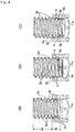
- a self-tapping screw has a base structure that includes a head 1 with an engagement groove engaging with the tip of a driver bit and a shank 2 extending from the center of the lower surface of the head 1, the outer peripheral surface of the shank 2 being provided with a single external screw thread 3.
- the shank 2 includes a cylindrical shank 2a immediately below the head and a truncated conical shank 2b following an end (i.e. a lower end) of the cylindrical shank 2a.
- the shank 2 of the self-tapping screw according to this embodiment has a circular cross-section perpendicular to the shank 2 that is the same diameter from the proximal end to the distal end thereof in the cylindrical shank 2a and has a circular cross-section perpendicular to the shank 2 that has a smaller diameter moving to the end thereof in the truncated conical shank 2b.
- the external screw thread 3 includes a first external thread or a plurality of first external threads 3a formed on the outer peripheral surface of the cylindrical shank 2a and a second external thread or a plurality of second external threads 3b formed on the outer peripheral surface of the truncated conical shank 2b, where the first external threads 3a and the second external threads 3b are continuous.
- a peak of each of the second external threads 3b is provided with a biting surface 4 having a concave-convex form.
- the biting surface 4 has an upper convex portion 4a at an upper end and a lower convex portion 4b at a lower end and has a concave portion 4c between the upper convex portion 4a and the lower convex portion 4b, where the concave portion 4c also has a rough surface with micro-irregularities, thereby contributing to the improvement of the initial biting performance and preventing or reducing the production of chips by plastically deforming the inner peripheral surface of a pilot hole properly.
- the upper convex portion 4a protrudes slightly outside of the lower convex portion 4b.
- the second external thread 3b is formed such that its height is reduced toward the end of the truncated conical shank 2b, and projecting heights of the upper convex portion 4a and the lower convex portion 4b of the biting surface 4 on the peak of the second external thread 3b is also formed to be reduced toward the end thereof, thereby improving initial biting performance as well as reducing initial torque.
- a first external thread or a plurality of first external threads 3a formed on the end portion of the cylindrical shank 2a and a second external thread or a plurality of second external threads 3b formed on the truncated conical shank 2b are provided with a plurality of no-thread parts 5 at regular intervals in a circumferential direction.
- first external threads 3a formed on the end portion of the cylindrical shank 2a are provided, at regular intervals in the circumferential direction, with first no-thread parts 5a where peaks are recessed in a concave curved shape
- second external threads 3b following the first external threads 3a with the no-thread parts 5a are provided with second no-thread parts 5b where peaks or upper and lower flanks are recessed in a concave curved shape.
- the first no-thread parts 5a and the second no-thread parts 5b are formed to be arranged on the same generatrix of the shank 2 with the same circumferential spacing between the first no-thread parts 5a and between the second no-thread parts 5b.
- This embodiment illustrates that three first no-thread parts 5a are formed at 120 degree intervals for a first external thread 3a, and likewise, three second no-thread parts 5b are formed at 120 degree intervals for a second external thread 3b.
- the second no-thread parts 5b prevent an increase in the initial torque due to the biting surface 4 of the second external thread 3b, and the first no-thread parts 5a contributes to reduction in screwing torque of the first external threads 3a following the second external threads 3b.
- first external threads 3a a first external thread or a plurality of first external threads 3a other than first external threads 3a with the first no-thread parts 5a are formed to the same thread height on the outer peripheral surface of the cylindrical shank 2a as illustrated in FIGS. 1 to 3 and are screwed following the second external threads 3b and the first external threads 3a with the first no-thread parts 5a.
- accurate internal threads are formed by plastic forming.
- part of the first external threads 3a other than the first external threads 3a with the first no-thread parts 5a may be optionally provided with a bulging peak protruding slightly outward.
- an end of the shank 2 i.e., an end of the truncated conical shank 2b
- an end of the shank 2 is first inserted into an inner peripheral surface 11a of a pilot hole 11, as illustrated in FIG. 4A , and the biting surface 4 at the peak of the second external thread 3b formed on the truncated conical shank 2b engages with the inner peripheral surface 11a of the pilot hole.
- a biting surface 4 of any of the second external threads 3b securely bites into the inner peripheral surface 11a of the pilot hole depending on the inner diameter of the inner peripheral surface 11a of the pilot hole, thereby appropriately maintaining the screwing attitude of the self-tapping screw.
- the upper convex portion 4a or both of the upper and lower convex portions 4a, 4b of the biting surface 4 bite into the inner peripheral surface 11a of the pilot hole, part of the material of the inner peripheral surface 11a plastically deformed by the bite makes contact with and engages with the concave portion 4c, and the biting surface 4 including the upper and lower convex portions 4a, 4b and the concave portion 4c bites into the inner peripheral surface 11a of the pilot hole. This prevents the inner peripheral surface 11a of the pilot hole to be inadvertently damaged while achieving appropriate initial biting performance.
- the second external threads 3b are provided with the second no-thread parts 5b, which allow the biting surface 4 to achieve the initial biting performance as well as to reduce the initial torque.
- the second external threads 3b biting into the inner peripheral surface 11a of the pilot hole plastically forms internal threads as well as guides subsequent first external threads 3a into the plastically formed internal threads.
- the first external threads 3a following the second external threads 3b are provided with the first no-thread parts 5a as described above, and the first no-thread parts 5a allows the first external threads 3a to be screwed at low torque.
- first external threads 3a with no first no-thread parts 5a continues to plastically form accurate internal threads, and screwing is completed such that the first external threads 3a are screwed up to the proximal end of the shank 2.
- the self-tapping screw of the invention can not only achieve the initial biting performance through the second external threads 3b, but also does not inadvertently damage the inner peripheral surface 11a of the pilot hole, thereby preventing or reducing the production of chips.
- the self-tapping screw guides the subsequent first external threads 3a while roughly machining the internal threads using the second external threads 3b, and the first external threads 3a plastically forms accurate internal threads.
- FIG. 5 illustrates a blank from which a screw is made.
- the blank includes a head 1 with an engagement groove engaging with the tip of a driver bit and a shank 2 extending from the center of the lower surface of the head 1, and the shank 2 is formed to have a structure including a cylindrical shank 2a immediately below the head 1 and a truncated conical shank 2b following an end of the cylindrical shank 2a.
- the blank is formed by known heading method.
- ⁇ 1 represents a taper angle of the truncated conical shank 2b
- O represents an external thread starting point position, i.e., a level at which the external screw thread 3 (second external thread 3b) starts on the outer peripheral surface of the truncated conical shank 2b.
- the external thread starting point position O is not necessarily located at an end of the outer peripheral surface of the truncated conical shank 2b and it may be optionally provided at the middle portion of the outer peripheral surface in accordance with some aspects.
- a portion spanning the cylindrical shank 2a and the truncated conical shank 2b i.e., a portion spanning a distal end side (lower side) of the cylindrical shank 2a and a proximal end side (upper side) of the truncated conical shank 2b is provided with a plurality of flat portions 6 for forming the no-thread parts 5 at regular intervals in the circumferential direction.
- the width, area, or number of the flat portions 6 is appropriately adjusted based on the size, shape, and number of desired no-thread parts 5.
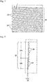
- the single external screw thread 3 is formed by rolling on the outer peripheral surface of the shank 2 (cylindrical shank 2a and truncated conical shank 2b). That is, as illustrated in FIG. 6 , a pair of rolling die plates 21A, 21B mounted on a rolling machine forms the external screw thread 3 on the outer peripheral surface of the shank 2 by rolling the shank 2 of the blank between rolling surfaces 22 of the rolling die plates 21A, 21B.
- one die plate 21A is referred to as a moving-side die plate and the other die plate 21B is referred to as a fixed-side die plate.
- a left end of the rolling surface 22 of the fixed-side die plate 21B is opposite to a right end of the rolling surface 22 of the moving-side die plate 21A, and the opposite rolling surfaces 22 hold the shank 2 of the blank therebetween.
- a blank material on the outer peripheral surface of the shank 2 is plastically deformed to form the external screw thread 3 on the outer peripheral surface of the shank 2 by moving the moving-side die plate 21A in the right direction.
- rolling is completed when the rolling surface 22 of the moving-side die plate 21A has passed the right end of the fixed-side die plate 21B.
- the rolling surfaces 22 of both the pair of rolling die plates 21A, 21B are provided with multiple grooves 23 for forming external threads as illustrated in FIG. 7 , where the grooves 23 are inclined at a lead angle ⁇ .
- a desired external screw thread 3 is formed on the shank 2 of the blank by adjusting the width, depth, spacing, etc. of the grooves 23.
- the rolling surface 22 is provided with a vertical surface 22a and an inclined surface 22b that follows a lower end of the vertical surface 22a and is inclined so as to narrow a gap with the other opposing rolling surface 22.
- a taper angle ⁇ 2 of the inclined surface 22b is set to be smaller than the above-described taper angle ⁇ 1 of the truncated conical shank 2b of the blank.
- a vertical length of the inclined surface 22b is appropriately adjusted so that the inclined surface 22b can make contact with the external thread starting point position O on the outer peripheral surface of the truncated conical shank 2b.
- rolling is started with the inclined surface 22b of each rolling surface 22 in contact with the external thread starting point position O on the outer peripheral surface of the truncated conical shank 2b of the blank.
- the blank material on the periphery of the truncated conical shank 2b in the upper level than the external thread starting point position O is plastically deformed to form the second external threads 3b, as illustrated in FIG. 9B
- the blank material on the periphery of the cylindrical shank 2a is plastically deformed to form the first external threads 3a.
- the second external thread 3b is formed that has the biting surface 4 with the above-described concave-convex form, i.e., the biting surface 4 that is formed, as illustrated in FIG.
- Rolling is carried out with the external thread starting point position O on the outer peripheral surface of the truncated conical shank 2b in contact with the inclined surface 22b of each rolling surface 22 so that the second external thread 3b can be formed by being securely and properly raised from its starting point.
- first and second no-thread parts 5a, 5b are formed at positions corresponding to the flat portions 6 formed on the shank 2 of the blank.
- the self-tapping screw according to the present invention has the biting surface 4 having a concave-convex form on the peak of the second external thread 3b formed on the truncated conical shank 2b in the end side of the shank 2, and the biting surface 4 allows the initial biting performance to be effectively achieved.
- the concave-convex form of the biting surface 4 can plastically deform the inner peripheral surface of the pilot hole properly, thereby preventing or reducing the production of chips.
- the second no-thread parts 5b formed on the second external threads 3b allow the biting surface 4 to achieve the initial biting performance as well as to reduce the initial torque.
- the method of manufacturing the self-tapping screw according to the present invention can form the second external threads 3b having the biting surface 4 by properly raising the second external threads 3b.
Landscapes
- Engineering & Computer Science (AREA)
- General Engineering & Computer Science (AREA)
- Mechanical Engineering (AREA)
- Physics & Mathematics (AREA)
- Geometry (AREA)
- Forging (AREA)
- Connection Of Plates (AREA)
Description
- The present invention relates to a self-tapping screw provided with an external thread for plastically forming an internal thread on the inner peripheral surface of a pilot hole.
- At the beginning of screwing, such a self-tapping screw forces its external thread, which first makes contact with the inner peripheral surface of a pilot hole with no internal thread, to bite into the inner peripheral surface so that the self-tapping screw guides a subsequent external thread smoothly while maintaining screwing attitude thereof and plastically forms an internal thread on the inner peripheral surface of the pilot hole.
-
JP 3338649 B1 - In the self-tapping screw disclosed in
JP 3338649 B1 - As described above, such a flat surface-shaped peak may be unable to plastically form a suitable internal thread and to guide a subsequent external thread smoothly.
- In addition, the external thread having the flat surface-shaped peak is formed on the outer periphery of the shank with the equilateral triangle cross-section so that only external thread portions at the vertices of the equilateral triangle contributes to plastic forming to form the internal thread. Also in this regard, a suitable internal thread may not be formed by plastic forming.
- A further self-tapping screw is disclosed in document
WO 2011/153619 A . - The present invention is to provide a self-tapping screw and a method of manufacturing the same that efficiently solve the problems of a conventional self-tapping screw described above and improve initial biting performance.
- Briefly, a self-tapping screw according to the present invention has the features of claim 1, whereby the initial biting performance is improved by the biting surface and an appropriate screwing attitude is maintained.
- The self-tapping screw is preferably structured such that the first external thread is formed on an end portion of the cylindrical shank and provided with a plurality of no-thread parts at regular intervals in a circumferential direction and the second external thread is formed on the truncated conical shank and provided with a plurality of no-thread parts at regular intervals in a circumferential direction, whereby both the no-thread parts reduce an initial torque without degrading the initial biting performance of the biting surface and guide subsequent external threads smoothly, allowing for smooth plastic forming to form internal threads.
- There is also provided a method of manufacturing the self-tapping screw according to
claim 3. - Preferably, the blank is provided with a plurality of flat portions spanning the cylindrical shank and the truncated conical shank at regular intervals in the circumferential direction. The flat portions are used to form a plurality of no-thread parts on a plurality of first external threads on the end portion of the cylindrical shank at regular intervals in the circumferential direction and to form a plurality of no-thread parts on the plurality of second external threads on the truncated conical shank at regular intervals in the circumferential direction.
- The present invention can provide a self-tapping screw that achieves appropriate initial biting performance using the second external threads with the biting surface at a shank end. The second external threads with the biting surface can be formed so as to be raised properly.
- In addition, since the biting surface does not inadvertently damage the inner peripheral surface of a pilot hole, the production of chips may be effectively prevented.
- Both of improvement of the initial biting performance and reduction in the initial torque can be achieved by forming a plurality of no-thread parts on the second external threads with the biting surface.
-
-
FIG. 1 is a front view of a self-tapping screw according to the present invention; -
FIG. 2 is a perspective view of the self-tapping screw according to the present invention; -
FIG. 3 is an enlarged cross-sectional view of a shank; -
FIG. 4A illustrates engagement of an external thread with the inner peripheral surface of a pilot hole when a shank end is inserted into the inner peripheral surface of the pilot hole,FIG. 4B illustrates engagement of external threads with the inner peripheral surface of the pilot hole when the shank is rotated by 180 degrees from the position illustrated inFIG. 4A, and FIG. 4C illustrates engagement of external threads with the inner peripheral surface of the pilot hole when the shank is rotated by 360 degrees from the position illustrated inFIG. 4A ; -
FIG. 5A is a front view of a blank (i.e., a screw material) andFIG. 5B is a bottom view of the blank; -
FIGS. 6A to 6C illustrate situations where the external thread is made by rolling with the shank of the blank sandwiched between a pair of rolling die plates, whereFIG. 6A illustrates a situation where rolling is started,FIG. 6B illustrates a situation where rolling is carried out, andFIG. 6C illustrates a situation where rolling is completed; -
FIG. 7 is an enlarged surface view of a rolling surface of the rolling die plate; -
FIG. 8 is an enlarged sectional view of the rolling surface of the rolling die plate; and -
FIGS. 9A and 9B illustrate a relationship between the blank and the pair of rolling die plates, whereFIG. 9A illustrates a situation where rolling is started andFIG. 9B illustrates a situation where rolling is completed. - The best mode of the present invention will now be described with reference to
FIG. 1 to FIGS. 9A and9B . - As illustrated in
FIGS. 1 and 2 , a self-tapping screw according to the invention has a base structure that includes a head 1 with an engagement groove engaging with the tip of a driver bit and ashank 2 extending from the center of the lower surface of the head 1, the outer peripheral surface of theshank 2 being provided with a singleexternal screw thread 3. - The
shank 2 includes acylindrical shank 2a immediately below the head and a truncatedconical shank 2b following an end (i.e. a lower end) of thecylindrical shank 2a. Thus, theshank 2 of the self-tapping screw according to this embodiment has a circular cross-section perpendicular to theshank 2 that is the same diameter from the proximal end to the distal end thereof in thecylindrical shank 2a and has a circular cross-section perpendicular to theshank 2 that has a smaller diameter moving to the end thereof in the truncatedconical shank 2b. - The
external screw thread 3 includes a first external thread or a plurality of firstexternal threads 3a formed on the outer peripheral surface of thecylindrical shank 2a and a second external thread or a plurality of secondexternal threads 3b formed on the outer peripheral surface of the truncatedconical shank 2b, where the firstexternal threads 3a and the secondexternal threads 3b are continuous. - Moreover, a peak of each of the second
external threads 3b is provided with abiting surface 4 having a concave-convex form. As illustrated inFIG. 3 , thebiting surface 4 has anupper convex portion 4a at an upper end and alower convex portion 4b at a lower end and has aconcave portion 4c between theupper convex portion 4a and thelower convex portion 4b, where theconcave portion 4c also has a rough surface with micro-irregularities, thereby contributing to the improvement of the initial biting performance and preventing or reducing the production of chips by plastically deforming the inner peripheral surface of a pilot hole properly. Theupper convex portion 4a protrudes slightly outside of thelower convex portion 4b. - Preferably, the second
external thread 3b is formed such that its height is reduced toward the end of the truncatedconical shank 2b, and projecting heights of theupper convex portion 4a and thelower convex portion 4b of thebiting surface 4 on the peak of the secondexternal thread 3b is also formed to be reduced toward the end thereof, thereby improving initial biting performance as well as reducing initial torque. - Also, as illustrated in
FIGS. 1 and 2 , a first external thread or a plurality of firstexternal threads 3a formed on the end portion of thecylindrical shank 2a and a second external thread or a plurality of secondexternal threads 3b formed on the truncatedconical shank 2b are provided with a plurality of no-thread parts 5 at regular intervals in a circumferential direction. - More specifically, the first
external threads 3a formed on the end portion of thecylindrical shank 2a are provided, at regular intervals in the circumferential direction, with first no-thread parts 5a where peaks are recessed in a concave curved shape, and the secondexternal threads 3b following the firstexternal threads 3a with the no-thread parts 5a are provided with second no-thread parts 5b where peaks or upper and lower flanks are recessed in a concave curved shape. - The first no-
thread parts 5a and the second no-thread parts 5b are formed to be arranged on the same generatrix of theshank 2 with the same circumferential spacing between the first no-thread parts 5a and between the second no-thread parts 5b. This embodiment illustrates that three first no-thread parts 5a are formed at 120 degree intervals for a firstexternal thread 3a, and likewise, three second no-thread parts 5b are formed at 120 degree intervals for a secondexternal thread 3b. - The second no-
thread parts 5b prevent an increase in the initial torque due to thebiting surface 4 of the secondexternal thread 3b, and the first no-thread parts 5a contributes to reduction in screwing torque of the firstexternal threads 3a following the secondexternal threads 3b. - Of the first
external threads 3a, a first external thread or a plurality of firstexternal threads 3a other than firstexternal threads 3a with the first no-thread parts 5a are formed to the same thread height on the outer peripheral surface of thecylindrical shank 2a as illustrated inFIGS. 1 to 3 and are screwed following the secondexternal threads 3b and the firstexternal threads 3a with the first no-thread parts 5a. Thus, accurate internal threads are formed by plastic forming. In accordance with some aspects, part of the firstexternal threads 3a other than the firstexternal threads 3a with the first no-thread parts 5a may be optionally provided with a bulging peak protruding slightly outward. - In the following, the initial biting performance into the inner peripheral surface of a pilot hole in using the above-structured self-tapping screw according to the present invention is described.
- In use of the above-structured self-tapping screw according to the invention, an end of the
shank 2, i.e., an end of the truncatedconical shank 2b, is first inserted into an innerperipheral surface 11a of apilot hole 11, as illustrated inFIG. 4A , and thebiting surface 4 at the peak of the secondexternal thread 3b formed on the truncatedconical shank 2b engages with the innerperipheral surface 11a of the pilot hole. - That is, a biting
surface 4 of any of the secondexternal threads 3b securely bites into the innerperipheral surface 11a of the pilot hole depending on the inner diameter of the innerperipheral surface 11a of the pilot hole, thereby appropriately maintaining the screwing attitude of the self-tapping screw. - At this time, the upper
convex portion 4a or both of the upper and lowerconvex portions biting surface 4 bite into the innerperipheral surface 11a of the pilot hole, part of the material of the innerperipheral surface 11a plastically deformed by the bite makes contact with and engages with theconcave portion 4c, and thebiting surface 4 including the upper and lowerconvex portions concave portion 4c bites into the innerperipheral surface 11a of the pilot hole. This prevents the innerperipheral surface 11a of the pilot hole to be inadvertently damaged while achieving appropriate initial biting performance. - As described above, the second
external threads 3b are provided with the second no-thread parts 5b, which allow thebiting surface 4 to achieve the initial biting performance as well as to reduce the initial torque. - When the self-tapping screw is then rotated and screwed as illustrated in
FIGS. 4B and 4C , the secondexternal threads 3b biting into the innerperipheral surface 11a of the pilot hole plastically forms internal threads as well as guides subsequent firstexternal threads 3a into the plastically formed internal threads. In this regard, the firstexternal threads 3a following the secondexternal threads 3b are provided with the first no-thread parts 5a as described above, and the first no-thread parts 5a allows the firstexternal threads 3a to be screwed at low torque. - Thereafter, the first
external threads 3a with no first no-thread parts 5a continues to plastically form accurate internal threads, and screwing is completed such that the firstexternal threads 3a are screwed up to the proximal end of theshank 2. - As described above, the self-tapping screw of the invention can not only achieve the initial biting performance through the second
external threads 3b, but also does not inadvertently damage the innerperipheral surface 11a of the pilot hole, thereby preventing or reducing the production of chips. The self-tapping screw guides the subsequent firstexternal threads 3a while roughly machining the internal threads using the secondexternal threads 3b, and the firstexternal threads 3a plastically forms accurate internal threads. - A method of manufacturing the above-structured self-tapping screw according to the present invention will now be described.
-
FIG. 5 illustrates a blank from which a screw is made. The blank includes a head 1 with an engagement groove engaging with the tip of a driver bit and ashank 2 extending from the center of the lower surface of the head 1, and theshank 2 is formed to have a structure including acylindrical shank 2a immediately below the head 1 and a truncatedconical shank 2b following an end of thecylindrical shank 2a. The blank is formed by known heading method. - In
FIG. 5A , θ1 represents a taper angle of the truncatedconical shank 2b, and O represents an external thread starting point position, i.e., a level at which the external screw thread 3 (secondexternal thread 3b) starts on the outer peripheral surface of the truncatedconical shank 2b. The external thread starting point position O is not necessarily located at an end of the outer peripheral surface of the truncatedconical shank 2b and it may be optionally provided at the middle portion of the outer peripheral surface in accordance with some aspects. - A portion spanning the
cylindrical shank 2a and the truncatedconical shank 2b, i.e., a portion spanning a distal end side (lower side) of thecylindrical shank 2a and a proximal end side (upper side) of the truncatedconical shank 2b is provided with a plurality offlat portions 6 for forming the no-thread parts 5 at regular intervals in the circumferential direction. The width, area, or number of theflat portions 6 is appropriately adjusted based on the size, shape, and number of desired no-thread parts 5. - In the present embodiment, the single
external screw thread 3 is formed by rolling on the outer peripheral surface of the shank 2 (cylindrical shank 2a and truncatedconical shank 2b). That is, as illustrated inFIG. 6 , a pair of rollingdie plates external screw thread 3 on the outer peripheral surface of theshank 2 by rolling theshank 2 of the blank between rollingsurfaces 22 of the rollingdie plates - More specifically, one
die plate 21A is referred to as a moving-side die plate and theother die plate 21B is referred to as a fixed-side die plate. As illustrated inFIG. 6A , a left end of the rollingsurface 22 of the fixed-side die plate 21B is opposite to a right end of the rollingsurface 22 of the moving-side die plate 21A, and the opposite rolling surfaces 22 hold theshank 2 of the blank therebetween. Then, as illustrated inFIG. 6B , a blank material on the outer peripheral surface of theshank 2 is plastically deformed to form theexternal screw thread 3 on the outer peripheral surface of theshank 2 by moving the moving-side die plate 21A in the right direction. Subsequently, as illustrated inFIG. 6C , rolling is completed when the rollingsurface 22 of the moving-side die plate 21A has passed the right end of the fixed-side die plate 21B. - The rolling surfaces 22 of both the pair of rolling
die plates multiple grooves 23 for forming external threads as illustrated inFIG. 7 , where thegrooves 23 are inclined at a lead angle α. A desiredexternal screw thread 3 is formed on theshank 2 of the blank by adjusting the width, depth, spacing, etc. of thegrooves 23. - In the present invention, as illustrated in
FIG. 8 , the rollingsurface 22 is provided with avertical surface 22a and aninclined surface 22b that follows a lower end of thevertical surface 22a and is inclined so as to narrow a gap with the other opposing rollingsurface 22. - A taper angle θ2 of the
inclined surface 22b is set to be smaller than the above-described taper angle θ1 of the truncatedconical shank 2b of the blank. A vertical length of theinclined surface 22b is appropriately adjusted so that theinclined surface 22b can make contact with the external thread starting point position O on the outer peripheral surface of the truncatedconical shank 2b. - Thus, as illustrated in
FIG. 9A , rolling is started with theinclined surface 22b of each rollingsurface 22 in contact with the external thread starting point position O on the outer peripheral surface of the truncatedconical shank 2b of the blank. - When rolling is carried out in such a way as described with reference to
FIGS. 6A-6C , the blank material on the periphery of the truncatedconical shank 2b in the upper level than the external thread starting point position O is plastically deformed to form the secondexternal threads 3b, as illustrated inFIG. 9B , and the blank material on the periphery of thecylindrical shank 2a is plastically deformed to form the firstexternal threads 3a. - Since the taper angle θ2 of the
inclined surface 22b is smaller than the taper angle θ1 of the truncatedconical shank 2b, the pressure that the peripheral surface of the truncatedconical shank 2b receives from theinclined surface 22b gradually decreases toward the end of the truncatedconical shank 2b and, on the farther end of the truncatedconical shank 2b, thegrooves 23 for forming the external thread is filled with less blank material in rolling. Thus, the secondexternal thread 3b is formed that has thebiting surface 4 with the above-described concave-convex form, i.e., the bitingsurface 4 that is formed, as illustrated inFIG. 3 , to have the upperconvex portion 4a at the upper end, the lowerconvex portion 4b at the lower end, and theconcave portion 4c between the upperconvex portion 4a and the lowerconvex portion 4b, theconcave portion 4c being a rough surface with micro-irregularities. - Rolling is carried out with the external thread starting point position O on the outer peripheral surface of the truncated
conical shank 2b in contact with theinclined surface 22b of each rollingsurface 22 so that the secondexternal thread 3b can be formed by being securely and properly raised from its starting point. - Furthermore, the above-mentioned first and second no-
thread parts flat portions 6 formed on theshank 2 of the blank. - As described above, the self-tapping screw according to the present invention has the
biting surface 4 having a concave-convex form on the peak of the secondexternal thread 3b formed on the truncatedconical shank 2b in the end side of theshank 2, and thebiting surface 4 allows the initial biting performance to be effectively achieved. In addition, the concave-convex form of thebiting surface 4 can plastically deform the inner peripheral surface of the pilot hole properly, thereby preventing or reducing the production of chips. - The second no-
thread parts 5b formed on the secondexternal threads 3b allow thebiting surface 4 to achieve the initial biting performance as well as to reduce the initial torque. - Moreover, the method of manufacturing the self-tapping screw according to the present invention can form the second
external threads 3b having the bitingsurface 4 by properly raising the secondexternal threads 3b.
Claims (4)
- A self-tapping screw comprising:a head (1); anda shank (2) extending from the head (1),the shank including a cylindrical shank (2a) immediately below the head (1) and a truncated conical shank (2b) following an end of the cylindrical shank,the cylindrical shank (2a) being provided with a first external thread (3a),the truncated conical shank (2b) being provided with a second external thread (3b) following the first external thread (3a),a peak of the second external thread (3b) being provided with a biting surface (4) having
a first convex portion (4a) and a second convex portion (4b) and having a concave portion (4c) between the first convex portion (4a) and the second convex portion (4b), wherein the concave portion (4c) has a rough surface with micro-irregularities, whereinthe biting surface is arranged to bite into an inner peripheral surface (11a) of a pilot hole (11). - The self-tapping screw according to claim 1, wherein
the first external thread (3a) formed on an end portion of the cylindrical shank (2a) is provided with a plurality of no-thread parts (5a) at regular intervals in a circumferential direction, and
the second external thread (3b) formed on the truncated conical shank (2b) is provided with a plurality of no-thread parts (5b) at regular intervals in a circumferential direction. - A method of manufacturing the self-tapping screw claimed in claim 1, the method comprising the steps of:A) forming a blank with a shank (2) including a cylindrical shank (2a) and a truncated conical shank (2b),B) forming, on each of opposing rolling surfaces (22) of a pair of rolling die plates, a vertical surface (22a) and an inclined surface (22b) that follows a lower end of the vertical surface (22a) and is inclined so as to narrow a gap with the other opposing rolling surface (22),C) setting a taper angle of the inclined surface (22b) of the rolling surface (22) to be smaller than a taper angle of the truncated conical shank (2b) of the blank, andD) carrying out rolling with the inclined surfaces (22b) of the rolling surfaces (22) in contact with an external thread starting point position on the outer peripheral surface of the truncated conical shank (2b) between the rolling surfaces (22) of the pair of rolling die plates and forming the first external thread (3a) and the second external thread (3b) with the biting surface (4) by rolling.
- The method of manufacturing the self-tapping screw according to claim 3, wherein
the blank is provided with a plurality of flat portions (6) spanning the cylindrical shank (2a) and the truncated conical shank (2b) at regular intervals in the circumferential direction, and
the flat portions (6) are used to form a plurality of no-thread parts (5) on the first external thread (3a) on the end portion of the cylindrical shank (2a) at regular intervals in the circumferential direction and to form a plurality of no-thread parts (5) on the second external thread (3b) on the truncated conical shank (2b) at regular intervals in the circumferential direction.
Applications Claiming Priority (1)
| Application Number | Priority Date | Filing Date | Title |
|---|---|---|---|
| JP2015040298A JP5770399B1 (en) | 2015-03-02 | 2015-03-02 | Self-tapping screw and manufacturing method thereof |
Publications (2)
| Publication Number | Publication Date |
|---|---|
| EP3064787A1 EP3064787A1 (en) | 2016-09-07 |
| EP3064787B1 true EP3064787B1 (en) | 2019-04-17 |
Family
ID=54187172
Family Applications (1)
| Application Number | Title | Priority Date | Filing Date |
|---|---|---|---|
| EP15194574.8A Active EP3064787B1 (en) | 2015-03-02 | 2015-11-13 | Self-tapping screw and method of manufacturing the same |
Country Status (8)
| Country | Link |
|---|---|
| US (1) | US9926962B2 (en) |
| EP (1) | EP3064787B1 (en) |
| JP (1) | JP5770399B1 (en) |
| KR (1) | KR102528206B1 (en) |
| CN (1) | CN105937534B (en) |
| MX (1) | MX365628B (en) |
| MY (1) | MY181613A (en) |
| ZA (1) | ZA201508497B (en) |
Families Citing this family (4)
| Publication number | Priority date | Publication date | Assignee | Title |
|---|---|---|---|---|
| KR102070888B1 (en) | 2017-12-19 | 2020-01-29 | 엘지전자 주식회사 | Self-forming Screw |
| JP6626231B1 (en) * | 2019-05-21 | 2019-12-25 | 株式会社トープラ | Male thread member |
| US11930912B2 (en) * | 2020-05-15 | 2024-03-19 | Brome Bird Care Inc. | Molded screw |
| DE102023104264A1 (en) * | 2023-02-21 | 2024-08-22 | Kamax Holding Gmbh & Co. Kg | Fasteners, fastener blanks and methods for producing fasteners |
Family Cites Families (31)
| Publication number | Priority date | Publication date | Assignee | Title |
|---|---|---|---|---|
| GB943575A (en) * | 1961-04-26 | 1963-12-04 | Gen Am Transport | Thread-swaging and fastening screws |
| US3218905A (en) * | 1962-04-30 | 1965-11-23 | Nat Lock Co | Self-tapping or thread-forming screw |
| US3180126A (en) * | 1962-11-14 | 1965-04-27 | Textron Ind Inc | Self-tapping screw and method of manufacture |
| US3469491A (en) * | 1966-05-10 | 1969-09-30 | Eaton Yale & Towne | Self-tapping screw |
| US3520343A (en) * | 1967-09-18 | 1970-07-14 | Detroit Bank & Trust Co | Self-tapping locking screw |
| US3894570A (en) * | 1973-04-23 | 1975-07-15 | Dumont Aviat Associates | Self-tapping fastener |
| US3935785A (en) * | 1974-01-03 | 1976-02-03 | Rockford Headed Products, Inc. | Thread swaging screw |
| US4235149A (en) * | 1978-08-17 | 1980-11-25 | Veldman Donald R | Self-thread creating fastener and method and apparatus for making the same |
| JPS6179014A (en) | 1984-09-21 | 1986-04-22 | みのる産業株式会社 | Plastic product |
| US4973209A (en) * | 1985-03-28 | 1990-11-27 | Conti Fasteners Ag | Screw for contaminated pre-tapped holes |
| JPS62251513A (en) * | 1986-04-23 | 1987-11-02 | レツクスノ−ド・インコ−ポレ−テツド | Burying fitting |
| US4844676A (en) * | 1986-10-23 | 1989-07-04 | Pheoll Manufacturing Company, Inc. | Self-penetrating screw |
| US5088869A (en) * | 1991-01-24 | 1992-02-18 | Greenslade Joe E | Thread rolling screw |
| US5340254A (en) * | 1992-01-31 | 1994-08-23 | Textron Inc. | Thread forming screw for forming an internal thread in a low ductility material |
| US5141376A (en) * | 1992-02-03 | 1992-08-25 | Emhart Inc. | Self drilling screw |
| US5211520A (en) * | 1992-07-02 | 1993-05-18 | Mckinney Blake | Self-threading fastener |
| JPH0738724A (en) | 1993-07-22 | 1995-02-07 | Canon Inc | Ink jet type copying device |
| US5599149A (en) * | 1995-02-28 | 1997-02-04 | Anchor Bolt And Screw Company | Self-tapping floor screw |
| US5964560A (en) * | 1995-08-15 | 1999-10-12 | Henriksen; Arne | Screw fastener |
| JP3020904B2 (en) * | 1997-11-06 | 2000-03-15 | クラウン精密工業株式会社 | Self tapping screw |
| JP3338649B2 (en) | 1998-02-27 | 2002-10-28 | 日東精工株式会社 | Tapping screw |
| US5961267A (en) * | 1998-06-23 | 1999-10-05 | Textron Inc. | Thread forming fastener |
| US6494656B1 (en) * | 2001-09-13 | 2002-12-17 | Conti Fasteners Ag | Self-tapping screw, blank and method for joining thin workpieces and production method for the same |
| DE10235817B4 (en) * | 2002-08-05 | 2004-08-05 | Ejot Gmbh & Co. Kg | Self-tapping screw |
| US20060039775A1 (en) * | 2002-10-02 | 2006-02-23 | Hiromichi Mizuno | Tapping screw |
| DE102004034246B4 (en) * | 2004-07-15 | 2008-04-24 | Sfs Intec Holding Ag | screw |
| DE102006000269A1 (en) * | 2006-06-02 | 2007-12-06 | Hilti Ag | Thread-forming screw |
| DE102007010221A1 (en) * | 2007-02-28 | 2008-09-04 | Baier & Michels Gmbh & Co. Kg | Screw with a thread forming thread, blank for making the screw and screw connection |
| CA2707410C (en) * | 2010-06-10 | 2013-09-24 | Walther, Uli | Screw with dual edge on thread |
| JP5352709B1 (en) | 2012-05-15 | 2013-11-27 | 平田ネジ株式会社 | Anchor screw and screw rolling flat dies |
| CN104006050A (en) * | 2014-06-17 | 2014-08-27 | 飞雕电器集团有限公司 | Self-tapping screw suitable for soft plastic material connection |
-
2015
- 2015-03-02 JP JP2015040298A patent/JP5770399B1/en active Active
- 2015-11-13 EP EP15194574.8A patent/EP3064787B1/en active Active
- 2015-11-17 ZA ZA2015/08497A patent/ZA201508497B/en unknown
- 2015-11-23 US US14/948,784 patent/US9926962B2/en active Active
- 2015-11-26 KR KR1020150166224A patent/KR102528206B1/en active IP Right Grant
- 2015-11-30 CN CN201510853845.XA patent/CN105937534B/en active Active
- 2015-11-30 MY MYPI2015704357A patent/MY181613A/en unknown
- 2015-12-02 MX MX2015016609A patent/MX365628B/en active IP Right Grant
Non-Patent Citations (1)
| Title |
|---|
| None * |
Also Published As
| Publication number | Publication date |
|---|---|
| MY181613A (en) | 2020-12-29 |
| EP3064787A1 (en) | 2016-09-07 |
| US20160258467A1 (en) | 2016-09-08 |
| JP2016161043A (en) | 2016-09-05 |
| MX2015016609A (en) | 2017-01-16 |
| CN105937534A (en) | 2016-09-14 |
| US9926962B2 (en) | 2018-03-27 |
| MX365628B (en) | 2019-06-10 |
| KR20160106481A (en) | 2016-09-12 |
| JP5770399B1 (en) | 2015-08-26 |
| CN105937534B (en) | 2020-02-21 |
| KR102528206B1 (en) | 2023-05-02 |
| ZA201508497B (en) | 2016-10-26 |
Similar Documents
| Publication | Publication Date | Title |
|---|---|---|
| US20220032362A1 (en) | Workpieces for making fasteners and tools | |
| EP3064787B1 (en) | Self-tapping screw and method of manufacturing the same | |
| JP5091904B2 (en) | Screw-in screwdriver | |
| JP4989784B1 (en) | Tapping screw | |
| US8757950B2 (en) | Structure of cross-shaped groove of screw for fit with driver bit | |
| JPS584207B2 (en) | Nejiyamas Ekomine Neji | |
| JP5362854B2 (en) | Raising tap with inner finish blade | |
| JP2003172330A (en) | Bolt and nut | |
| US4235149A (en) | Self-thread creating fastener and method and apparatus for making the same | |
| JP3604325B2 (en) | Rolling dies for rod-end screws | |
| US20060039775A1 (en) | Tapping screw | |
| EP2752589A1 (en) | Anti-seizing nut | |
| US4034586A (en) | Thread rolling die and method of thread rolling | |
| TWI749028B (en) | Rolling die for forming self-boring screw by rolling | |
| JP4954248B2 (en) | Self tapping screw | |
| CN106133345B (en) | Self-tapping screw and fastening structure thereof | |
| JP2015064041A (en) | Screw structure, screw component, screw cutting tap, driving rivet, process of manufacture of screw structure and rolling die | |
| EP3339665A1 (en) | Male threaded fastener | |
| JPH0637857Y2 (en) | Asymmetric screw build-up tap | |
| TWI622444B (en) | Mold punch for manufacturing fasteners | |
| JP3737001B2 (en) | Screwing unit of female screw member and male screw member | |
| JP5923820B2 (en) | Male thread manufacturing method | |
| JP2012052668A (en) | Head driving hole of screw component | |
| JP3960845B2 (en) | Rolling die for deep grooved screw and method for manufacturing deep grooved screw | |
| JP2004344952A (en) | Form-rolling die for screw with deep groove and method for manufacturing screw with deep groove |
Legal Events
| Date | Code | Title | Description |
|---|---|---|---|
| PUAI | Public reference made under article 153(3) epc to a published international application that has entered the european phase |
Free format text: ORIGINAL CODE: 0009012 |
|
| AK | Designated contracting states |
Kind code of ref document: A1 Designated state(s): AL AT BE BG CH CY CZ DE DK EE ES FI FR GB GR HR HU IE IS IT LI LT LU LV MC MK MT NL NO PL PT RO RS SE SI SK SM TR |
|
| AX | Request for extension of the european patent |
Extension state: BA ME |
|
| STAA | Information on the status of an ep patent application or granted ep patent |
Free format text: STATUS: REQUEST FOR EXAMINATION WAS MADE |
|
| 17P | Request for examination filed |
Effective date: 20170215 |
|
| RBV | Designated contracting states (corrected) |
Designated state(s): AL AT BE BG CH CY CZ DE DK EE ES FI FR GB GR HR HU IE IS IT LI LT LU LV MC MK MT NL NO PL PT RO RS SE SI SK SM TR |
|
| GRAP | Despatch of communication of intention to grant a patent |
Free format text: ORIGINAL CODE: EPIDOSNIGR1 |
|
| STAA | Information on the status of an ep patent application or granted ep patent |
Free format text: STATUS: GRANT OF PATENT IS INTENDED |
|
| RIC1 | Information provided on ipc code assigned before grant |
Ipc: F16B 25/00 20060101AFI20181008BHEP |
|
| INTG | Intention to grant announced |
Effective date: 20181114 |
|
| GRAS | Grant fee paid |
Free format text: ORIGINAL CODE: EPIDOSNIGR3 |
|
| GRAA | (expected) grant |
Free format text: ORIGINAL CODE: 0009210 |
|
| STAA | Information on the status of an ep patent application or granted ep patent |
Free format text: STATUS: THE PATENT HAS BEEN GRANTED |
|
| AK | Designated contracting states |
Kind code of ref document: B1 Designated state(s): AL AT BE BG CH CY CZ DE DK EE ES FI FR GB GR HR HU IE IS IT LI LT LU LV MC MK MT NL NO PL PT RO RS SE SI SK SM TR |
|
| REG | Reference to a national code |
Ref country code: GB Ref legal event code: FG4D |
|
| REG | Reference to a national code |
Ref country code: CH Ref legal event code: EP |
|
| REG | Reference to a national code |
Ref country code: DE Ref legal event code: R096 Ref document number: 602015028386 Country of ref document: DE |
|
| REG | Reference to a national code |
Ref country code: AT Ref legal event code: REF Ref document number: 1121862 Country of ref document: AT Kind code of ref document: T Effective date: 20190515 Ref country code: IE Ref legal event code: FG4D |
|
| REG | Reference to a national code |
Ref country code: NL Ref legal event code: MP Effective date: 20190417 |
|
| REG | Reference to a national code |
Ref country code: LT Ref legal event code: MG4D |
|
| PG25 | Lapsed in a contracting state [announced via postgrant information from national office to epo] |
Ref country code: NL Free format text: LAPSE BECAUSE OF FAILURE TO SUBMIT A TRANSLATION OF THE DESCRIPTION OR TO PAY THE FEE WITHIN THE PRESCRIBED TIME-LIMIT Effective date: 20190417 |
|
| PG25 | Lapsed in a contracting state [announced via postgrant information from national office to epo] |
Ref country code: AL Free format text: LAPSE BECAUSE OF FAILURE TO SUBMIT A TRANSLATION OF THE DESCRIPTION OR TO PAY THE FEE WITHIN THE PRESCRIBED TIME-LIMIT Effective date: 20190417 Ref country code: ES Free format text: LAPSE BECAUSE OF FAILURE TO SUBMIT A TRANSLATION OF THE DESCRIPTION OR TO PAY THE FEE WITHIN THE PRESCRIBED TIME-LIMIT Effective date: 20190417 Ref country code: FI Free format text: LAPSE BECAUSE OF FAILURE TO SUBMIT A TRANSLATION OF THE DESCRIPTION OR TO PAY THE FEE WITHIN THE PRESCRIBED TIME-LIMIT Effective date: 20190417 Ref country code: LT Free format text: LAPSE BECAUSE OF FAILURE TO SUBMIT A TRANSLATION OF THE DESCRIPTION OR TO PAY THE FEE WITHIN THE PRESCRIBED TIME-LIMIT Effective date: 20190417 Ref country code: HR Free format text: LAPSE BECAUSE OF FAILURE TO SUBMIT A TRANSLATION OF THE DESCRIPTION OR TO PAY THE FEE WITHIN THE PRESCRIBED TIME-LIMIT Effective date: 20190417 Ref country code: NO Free format text: LAPSE BECAUSE OF FAILURE TO SUBMIT A TRANSLATION OF THE DESCRIPTION OR TO PAY THE FEE WITHIN THE PRESCRIBED TIME-LIMIT Effective date: 20190717 Ref country code: SE Free format text: LAPSE BECAUSE OF FAILURE TO SUBMIT A TRANSLATION OF THE DESCRIPTION OR TO PAY THE FEE WITHIN THE PRESCRIBED TIME-LIMIT Effective date: 20190417 Ref country code: PT Free format text: LAPSE BECAUSE OF FAILURE TO SUBMIT A TRANSLATION OF THE DESCRIPTION OR TO PAY THE FEE WITHIN THE PRESCRIBED TIME-LIMIT Effective date: 20190817 |
|
| PG25 | Lapsed in a contracting state [announced via postgrant information from national office to epo] |
Ref country code: RS Free format text: LAPSE BECAUSE OF FAILURE TO SUBMIT A TRANSLATION OF THE DESCRIPTION OR TO PAY THE FEE WITHIN THE PRESCRIBED TIME-LIMIT Effective date: 20190417 Ref country code: LV Free format text: LAPSE BECAUSE OF FAILURE TO SUBMIT A TRANSLATION OF THE DESCRIPTION OR TO PAY THE FEE WITHIN THE PRESCRIBED TIME-LIMIT Effective date: 20190417 Ref country code: GR Free format text: LAPSE BECAUSE OF FAILURE TO SUBMIT A TRANSLATION OF THE DESCRIPTION OR TO PAY THE FEE WITHIN THE PRESCRIBED TIME-LIMIT Effective date: 20190718 Ref country code: PL Free format text: LAPSE BECAUSE OF FAILURE TO SUBMIT A TRANSLATION OF THE DESCRIPTION OR TO PAY THE FEE WITHIN THE PRESCRIBED TIME-LIMIT Effective date: 20190417 Ref country code: BG Free format text: LAPSE BECAUSE OF FAILURE TO SUBMIT A TRANSLATION OF THE DESCRIPTION OR TO PAY THE FEE WITHIN THE PRESCRIBED TIME-LIMIT Effective date: 20190717 |
|
| REG | Reference to a national code |
Ref country code: AT Ref legal event code: MK05 Ref document number: 1121862 Country of ref document: AT Kind code of ref document: T Effective date: 20190417 |
|
| PG25 | Lapsed in a contracting state [announced via postgrant information from national office to epo] |
Ref country code: IS Free format text: LAPSE BECAUSE OF FAILURE TO SUBMIT A TRANSLATION OF THE DESCRIPTION OR TO PAY THE FEE WITHIN THE PRESCRIBED TIME-LIMIT Effective date: 20190817 |
|
| REG | Reference to a national code |
Ref country code: DE Ref legal event code: R097 Ref document number: 602015028386 Country of ref document: DE |
|
| PG25 | Lapsed in a contracting state [announced via postgrant information from national office to epo] |
Ref country code: AT Free format text: LAPSE BECAUSE OF FAILURE TO SUBMIT A TRANSLATION OF THE DESCRIPTION OR TO PAY THE FEE WITHIN THE PRESCRIBED TIME-LIMIT Effective date: 20190417 Ref country code: SK Free format text: LAPSE BECAUSE OF FAILURE TO SUBMIT A TRANSLATION OF THE DESCRIPTION OR TO PAY THE FEE WITHIN THE PRESCRIBED TIME-LIMIT Effective date: 20190417 Ref country code: RO Free format text: LAPSE BECAUSE OF FAILURE TO SUBMIT A TRANSLATION OF THE DESCRIPTION OR TO PAY THE FEE WITHIN THE PRESCRIBED TIME-LIMIT Effective date: 20190417 Ref country code: EE Free format text: LAPSE BECAUSE OF FAILURE TO SUBMIT A TRANSLATION OF THE DESCRIPTION OR TO PAY THE FEE WITHIN THE PRESCRIBED TIME-LIMIT Effective date: 20190417 Ref country code: DK Free format text: LAPSE BECAUSE OF FAILURE TO SUBMIT A TRANSLATION OF THE DESCRIPTION OR TO PAY THE FEE WITHIN THE PRESCRIBED TIME-LIMIT Effective date: 20190417 |
|
| PLBE | No opposition filed within time limit |
Free format text: ORIGINAL CODE: 0009261 |
|
| STAA | Information on the status of an ep patent application or granted ep patent |
Free format text: STATUS: NO OPPOSITION FILED WITHIN TIME LIMIT |
|
| PG25 | Lapsed in a contracting state [announced via postgrant information from national office to epo] |
Ref country code: IT Free format text: LAPSE BECAUSE OF FAILURE TO SUBMIT A TRANSLATION OF THE DESCRIPTION OR TO PAY THE FEE WITHIN THE PRESCRIBED TIME-LIMIT Effective date: 20190417 Ref country code: SM Free format text: LAPSE BECAUSE OF FAILURE TO SUBMIT A TRANSLATION OF THE DESCRIPTION OR TO PAY THE FEE WITHIN THE PRESCRIBED TIME-LIMIT Effective date: 20190417 |
|
| 26N | No opposition filed |
Effective date: 20200120 |
|
| PG25 | Lapsed in a contracting state [announced via postgrant information from national office to epo] |
Ref country code: TR Free format text: LAPSE BECAUSE OF FAILURE TO SUBMIT A TRANSLATION OF THE DESCRIPTION OR TO PAY THE FEE WITHIN THE PRESCRIBED TIME-LIMIT Effective date: 20190417 |
|
| PG25 | Lapsed in a contracting state [announced via postgrant information from national office to epo] |
Ref country code: SI Free format text: LAPSE BECAUSE OF FAILURE TO SUBMIT A TRANSLATION OF THE DESCRIPTION OR TO PAY THE FEE WITHIN THE PRESCRIBED TIME-LIMIT Effective date: 20190417 |
|
| REG | Reference to a national code |
Ref country code: CH Ref legal event code: PL |
|
| PG25 | Lapsed in a contracting state [announced via postgrant information from national office to epo] |
Ref country code: LI Free format text: LAPSE BECAUSE OF NON-PAYMENT OF DUE FEES Effective date: 20191130 Ref country code: LU Free format text: LAPSE BECAUSE OF NON-PAYMENT OF DUE FEES Effective date: 20191113 Ref country code: CH Free format text: LAPSE BECAUSE OF NON-PAYMENT OF DUE FEES Effective date: 20191130 Ref country code: MC Free format text: LAPSE BECAUSE OF FAILURE TO SUBMIT A TRANSLATION OF THE DESCRIPTION OR TO PAY THE FEE WITHIN THE PRESCRIBED TIME-LIMIT Effective date: 20190417 |
|
| REG | Reference to a national code |
Ref country code: BE Ref legal event code: MM Effective date: 20191130 |
|
| PG25 | Lapsed in a contracting state [announced via postgrant information from national office to epo] |
Ref country code: IE Free format text: LAPSE BECAUSE OF NON-PAYMENT OF DUE FEES Effective date: 20191113 |
|
| PG25 | Lapsed in a contracting state [announced via postgrant information from national office to epo] |
Ref country code: BE Free format text: LAPSE BECAUSE OF NON-PAYMENT OF DUE FEES Effective date: 20191130 |
|
| PG25 | Lapsed in a contracting state [announced via postgrant information from national office to epo] |
Ref country code: CY Free format text: LAPSE BECAUSE OF FAILURE TO SUBMIT A TRANSLATION OF THE DESCRIPTION OR TO PAY THE FEE WITHIN THE PRESCRIBED TIME-LIMIT Effective date: 20190417 |
|
| PG25 | Lapsed in a contracting state [announced via postgrant information from national office to epo] |
Ref country code: MT Free format text: LAPSE BECAUSE OF FAILURE TO SUBMIT A TRANSLATION OF THE DESCRIPTION OR TO PAY THE FEE WITHIN THE PRESCRIBED TIME-LIMIT Effective date: 20190417 Ref country code: HU Free format text: LAPSE BECAUSE OF FAILURE TO SUBMIT A TRANSLATION OF THE DESCRIPTION OR TO PAY THE FEE WITHIN THE PRESCRIBED TIME-LIMIT; INVALID AB INITIO Effective date: 20151113 |
|
| PG25 | Lapsed in a contracting state [announced via postgrant information from national office to epo] |
Ref country code: MK Free format text: LAPSE BECAUSE OF FAILURE TO SUBMIT A TRANSLATION OF THE DESCRIPTION OR TO PAY THE FEE WITHIN THE PRESCRIBED TIME-LIMIT Effective date: 20190417 |
|
| PGFP | Annual fee paid to national office [announced via postgrant information from national office to epo] |
Ref country code: GB Payment date: 20231129 Year of fee payment: 9 |
|
| PGFP | Annual fee paid to national office [announced via postgrant information from national office to epo] |
Ref country code: FR Payment date: 20231123 Year of fee payment: 9 Ref country code: DE Payment date: 20231124 Year of fee payment: 9 Ref country code: CZ Payment date: 20231113 Year of fee payment: 9 |