EP3002164B2 - Vehicle wiper device - Google Patents
Vehicle wiper device Download PDFInfo
- Publication number
- EP3002164B2 EP3002164B2 EP15184153.3A EP15184153A EP3002164B2 EP 3002164 B2 EP3002164 B2 EP 3002164B2 EP 15184153 A EP15184153 A EP 15184153A EP 3002164 B2 EP3002164 B2 EP 3002164B2
- Authority
- EP
- European Patent Office
- Prior art keywords
- blade
- cleaning liquid
- windshield
- cleaning
- liquid
- Prior art date
- Legal status (The legal status is an assumption and is not a legal conclusion. Google has not performed a legal analysis and makes no representation as to the accuracy of the status listed.)
- Active
Links
Images

Classifications
-
- B—PERFORMING OPERATIONS; TRANSPORTING
- B60—VEHICLES IN GENERAL
- B60S—SERVICING, CLEANING, REPAIRING, SUPPORTING, LIFTING, OR MANOEUVRING OF VEHICLES, NOT OTHERWISE PROVIDED FOR
- B60S1/00—Cleaning of vehicles
- B60S1/02—Cleaning windscreens, windows or optical devices
- B60S1/46—Cleaning windscreens, windows or optical devices using liquid; Windscreen washers
- B60S1/48—Liquid supply therefor
- B60S1/481—Liquid supply therefor the operation of at least part of the liquid supply being controlled by electric means
-
- B—PERFORMING OPERATIONS; TRANSPORTING
- B60—VEHICLES IN GENERAL
- B60S—SERVICING, CLEANING, REPAIRING, SUPPORTING, LIFTING, OR MANOEUVRING OF VEHICLES, NOT OTHERWISE PROVIDED FOR
- B60S1/00—Cleaning of vehicles
- B60S1/02—Cleaning windscreens, windows or optical devices
- B60S1/04—Wipers or the like, e.g. scrapers
- B60S1/06—Wipers or the like, e.g. scrapers characterised by the drive
- B60S1/08—Wipers or the like, e.g. scrapers characterised by the drive electrically driven
- B60S1/0814—Wipers or the like, e.g. scrapers characterised by the drive electrically driven using several drive motors; motor synchronisation circuits
-
- B—PERFORMING OPERATIONS; TRANSPORTING
- B60—VEHICLES IN GENERAL
- B60S—SERVICING, CLEANING, REPAIRING, SUPPORTING, LIFTING, OR MANOEUVRING OF VEHICLES, NOT OTHERWISE PROVIDED FOR
- B60S1/00—Cleaning of vehicles
- B60S1/02—Cleaning windscreens, windows or optical devices
- B60S1/46—Cleaning windscreens, windows or optical devices using liquid; Windscreen washers
- B60S1/48—Liquid supply therefor
- B60S1/481—Liquid supply therefor the operation of at least part of the liquid supply being controlled by electric means
- B60S1/482—Liquid supply therefor the operation of at least part of the liquid supply being controlled by electric means combined with the operation of windscreen wipers
-
- B—PERFORMING OPERATIONS; TRANSPORTING
- B60—VEHICLES IN GENERAL
- B60S—SERVICING, CLEANING, REPAIRING, SUPPORTING, LIFTING, OR MANOEUVRING OF VEHICLES, NOT OTHERWISE PROVIDED FOR
- B60S1/00—Cleaning of vehicles
- B60S1/02—Cleaning windscreens, windows or optical devices
- B60S1/04—Wipers or the like, e.g. scrapers
- B60S1/06—Wipers or the like, e.g. scrapers characterised by the drive
- B60S1/08—Wipers or the like, e.g. scrapers characterised by the drive electrically driven
- B60S1/0818—Wipers or the like, e.g. scrapers characterised by the drive electrically driven including control systems responsive to external conditions, e.g. by detection of moisture, dirt or the like
- B60S1/0822—Wipers or the like, e.g. scrapers characterised by the drive electrically driven including control systems responsive to external conditions, e.g. by detection of moisture, dirt or the like characterized by the arrangement or type of detection means
- B60S1/0833—Optical rain sensor
- B60S1/0844—Optical rain sensor including a camera
-
- B—PERFORMING OPERATIONS; TRANSPORTING
- B60—VEHICLES IN GENERAL
- B60S—SERVICING, CLEANING, REPAIRING, SUPPORTING, LIFTING, OR MANOEUVRING OF VEHICLES, NOT OTHERWISE PROVIDED FOR
- B60S1/00—Cleaning of vehicles
- B60S1/02—Cleaning windscreens, windows or optical devices
- B60S1/46—Cleaning windscreens, windows or optical devices using liquid; Windscreen washers
- B60S1/48—Liquid supply therefor
- B60S1/52—Arrangement of nozzles; Liquid spreading means
- B60S1/522—Arrangement of nozzles; Liquid spreading means moving liquid spreading means, e.g. arranged in wiper arms
- B60S1/524—Arrangement of nozzles; Liquid spreading means moving liquid spreading means, e.g. arranged in wiper arms arranged in wiper blades
Definitions
- the present invention relates to vehicle wiper devices.
- the present invention relates to a vehicle wiper device equipped with a blade having a cleaning-liquid ejecting function.
- a vehicle wiper device is used as a device that cleans the surface of a vehicle windshield by wiping off rainwater and dirt therefrom.
- the vehicle wiper device is provided with a blade at a moving end of a pivot arm and reciprocates this blade on the surface of the windshield so as to wipe and clean the windshield.
- a mechanism that feeds and ejects a cleaning liquid onto the surface of the windshield is also provided.
- a configuration that ejects the cleaning liquid directly from the blade is used so as to eject the cleaning liquid to a more appropriate position or region of the windshield.
- Japanese Unexamined Patent Application Publication No. 05-97017 discloses a wiper blade having a structure that sprays the cleaning liquid toward the glass surface.
- a packing member normally provided to blade rubber serving as the blade body has a cleaning-liquid feed passage.
- the cleaning liquid can be ejected relatively uniformly and to appropriate positions over a wide range of the windshield.
- the blade normally moves in a substantially circular pattern in a state where there is always a substantial amount of cleaning liquid in front of the blade in the moving direction thereof, the cleaning liquid tends to splatter outward in the radial direction of the moving region of the blade due to the effect of a centrifugal force generated as a result of the movement of the blade.
- the cleaning liquid may become pushed out to the upper mid region of the windshield as the second blade moves. Then, the cleaning liquid pushed out to the upper mid region of the windshield can no longer be wiped off with the second blade.
- the cleaning liquid remains in the upper mid region.
- this state in which the cleaning liquid remains in the upper mid region of the windshield is not preferred since the cleaning liquid may subsequently drip downward and remain in the main region of the windshield.
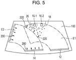
- Fig. 5 illustrates a problem in a vehicle having image capturing devices, such as cameras, disposed in the upper mid region of a windshield 100. Specifically, Fig. 5 illustrates how a cleaning liquid 26 splattering from a reciprocating second blade 14 in the radial direction thereof (indicated by an arrow 220) enters a specific region 18 on the windshield 100, which is a region including the field angle of image capturing devices 16-1 and 16-2. In this state in which the cleaning liquid 26 remains in the specific region 18, the function of the image capturing devices 16-1 and 16-2 is adversely affected.
- FR 2 991 948 A1 discloses a vehicle wiper device according to the preamble of claim 1.
- DE 10 2010 056 363 A1 discloses a control for a viper device of a vehicle and a viper device of a vehicle.
- an object of the present invention is to provide a vehicle wiper device equipped with a blade having a cleaning-liquid ejector, in which the vehicle wiper device can effectively prevent a cleaning liquid from remaining in a main region and an upper mid region of a windshield.
- an aspect of the present invention provides a vehicle wiper device including a first blade having an operating range that includes an upper mid region of a vehicle windshield; a second blade having an operating range that includes a lower region of the operating range of the first blade; a cleaning-liquid feeding unit that feeds a cleaning liquid to an ejector so as to eject the cleaning liquid onto the windshield; a blade driving unit that causes each blade to reciprocate within the corresponding operating range on the windshield; and a controller that controls operation of the cleaning-liquid feeding unit and operation of the blade driving unit.
- the controller controls the cleaning-liquid feeding unit and the blade driving unit such that, after a series of normal operation in which the first blade and the second blade reciprocate while ejecting the cleaning liquid has been completed, additional movement operation is performed in a state where feeding of the cleaning liquid from the cleaning-liquid feeding unit is stopped.
- the controller performs the control such that the additional movement operation is performed by either one of the first blade and the second blade or by both the first blade and the second blade at different timings.
- the controller may perform the control such that a moving range of the first blade in the movement operation is set to be larger than a moving range of the first blade in the normal operation.
- the controller may perform the control such that the feeding of the cleaning liquid is stopped only during a returning motion in the additional movement operation.
- Fig. 1 is a schematic configuration diagram of a vehicle wiper device 10 according to an example of the present invention and illustrates a front windshield 100 of a vehicle with a right-hand steering wheel, as viewed from the outside.
- a first blade 12 is provided at the passenger-seat side, which is the right side in Fig. 1
- a second blade 14 is provided at the driver-seat side, which is the left side.
- the left and right sides are inverted in the case of a vehicle with a left-hand steering wheel, a description thereof will be omitted below.
- Each of the blades 12 and 14 is attached to an end of a pivot arm (not illustrated) and pivots back and forth within a predetermined range in accordance with operation of the pivot arm.
- An operating area E1 of the first blade 12 includes an upper mid region of the windshield 100
- an operating area E2 of the second blade 14 includes a region below the upper mid region of the windshield 100.
- the operating area E1 and the operating area E2 partially overlap each other.
- a pair of cameras 16-1 and 16-2 as image capturing devices that are used for checking the conditions ahead is disposed at the inner side of the windshield 100.
- a region 18 indicated by a two-dot chain line in Fig. 1 corresponds to a field angle that is a photographic range of the cameras 16-1 and 16-2.
- the region 18 is referred to as "the specific region 18". Based on image information acquired with these cameras 16, the presence of, for instance, an object ahead and the distance thereto are detected and determined, such that control for assisting in driving of the vehicle is performed.
- each of the blades 12 and 14 has a cleaning-liquid ejector (not illustrated) that ejects a cleaning liquid in a direction indicated by arrows 200 in Fig. 1 .
- the cleaning liquid is ejected by causing ejection pumps 22a and 22b controlled by a controller 20 to feed the cleaning liquid to the blades 12 and 14.
- a cleaning-liquid feeding unit may refer to the entire configuration that includes the ejection pumps 22a and 22b and that feeds the cleaning liquid retained in a cleaning-liquid tank (not illustrated) to the cleaning-liquid ejectors of the blades 12 and 14.
- a blade driving unit may refer to the overall configuration that includes the drive motors 24a and 24b and that makes the pivot arms pivot.
- the operating speeds of the blades 12 and 14 can be controlled.
- the pressures of the ejection pumps 22a and 22b can be adjusted.
- the controller 20 includes a central processing unit (CPU), a read-only memory (ROM), and so on and is capable of independently or synchronously controlling the first blade 12 and the second blade 14, as described above.
- CPU central processing unit
- ROM read-only memory
- Fig. 2 illustrates the first blade 12 and the second blade 14 being additionally moved in a state where the feeding of the cleaning liquid from the cleaning-liquid feeding unit is stopped, after a series of normal operation in which the first blade 12 and the second blade 14 reciprocate while ejecting the cleaning liquid has been completed.
- the state illustrated in Fig. 2 corresponds to a returning motion in the additional movement operation. In this additional movement operation, the cleaning liquid is not fed to the first blade 12 and the second blade 14 such that the ejection of the cleaning liquid is stopped.
- the operating range of the first blade 12 includes the upper mid region of the windshield 100.
- the operating range of the second blade 14 includes a lower region of the operating range of the first blade 12. Therefore, by additionally moving the first blade 12 and the second blade 14 in the state where the ejection of the cleaning liquid is stopped, the upper mid region and the main region of the windshield 100 are wiped. Because the upper mid region includes the specific region 18 that includes the field angle of the cameras 16-1 and 16-2, the cleaning liquid and so on remaining in the specific region 18 are wiped off as a result of the additional movement operation of the first blade 12, whereby the function of the image capturing devices can be ensured.
- the main region of the windshield 100 is wiped, thereby maintaining good visibility. Accordingly, when the first blade 12 and the second blade 14 return to their accommodation positions (i.e., lower pivot positions), a good state is achieved in which there is hardly any remains, such as the cleaning liquid, on the windshield 100.
- the additional movement operation of the first blade 12 and the second blade 14 is performed while stopping the ejection of the cleaning liquid, it is also possible to stop the ejection of the cleaning liquid only during the returning motion in the additional movement operation.
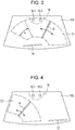
- Fig. 3 illustrates a state where the first blade 12 is reciprocated after a series of normal operation in which the first blade 12 and the second blade 14 reciprocate while ejecting the cleaning liquid has been completed.
- the first blade 12 is reciprocated once.
- the first blade 12 reciprocates over a larger moving range than in the normal operation of the first blade 12.
- a region expanded from that in the normal reciprocating operation is indicated by an arrow A.
- the first blade 12 reciprocates at a moving speed that is the same as that during the normal reciprocating operation thereof.
- the moving speed is appropriately changeable depending on the condition of the cleaning liquid and so on remaining on the windshield 100.
- the ejection of the cleaning liquid may be stopped only during the returning motion in the additional movement operation.
- the first blade 12 having an operating range that includes the specific region 18 corresponding to the field angle of the image capturing devices is additionally moved while the ejection of the cleaning liquid is stopped, the cleaning liquid and so on remaining in the specific region 18 and the main region of the windshield 100 can be appropriately wiped off.
- Fig. 4 illustrates a state where the second blade 14 is additionally reciprocated after a series of normal operation in which the first blade 12 and the second blade 14 reciprocate while ejecting the cleaning liquid has been completed.
- the second blade 14 is reciprocated once.
- This additional reciprocation of the second blade 14 is preferably performed upon completion of the additional reciprocation of the first blade 12.
- the moving speed of the second blade 14 during this reciprocation is the same as the moving speed thereof in the normal operation. However, the moving speed is appropriately changeable depending on the condition of the cleaning liquid and so on remaining on the windshield 100.
- the ejection of the cleaning liquid may be stopped only during the returning motion.
- the cleaning liquid and so on remaining on the windshield 100 at the driver-seat side can be appropriately wiped off, thereby ensuring good forward visibility of the vehicle and facilitating safe driving.
- the additional movement operation is performed in a state where the feeding of the cleaning liquid from the cleaning-liquid feeding unit is stopped.
- the additional movement operation is performed by both the first blade 12 and the second blade 14, by either one of the first blade 12 and the second blade 14, or by both the first blade 12 and the second blade 14 at different timings. Accordingly, the cleaning liquid and so on may be prevented from remaining in the specific region 18 corresponding to the field angle of the image capturing devices 16-1 and 16-2 and in the main region of the windshield 100, thereby maintaining the function of the image capturing devices and also ensuring good forward visibility of the vehicle.
- the moving speed of the first blade 12 during the additional movement operation is the same as the moving speed during the normal operation thereof, the moving speed may be changed in accordance with the condition of the windshield 100, the vehicle speed, and so on.
- the first blade 12 is reciprocated once, the number of times the first blade 12 is reciprocated may be set in accordance with the condition of the windshield 100. The same applies to the reciprocation of the second blade 14.
Landscapes
- Engineering & Computer Science (AREA)
- Mechanical Engineering (AREA)
- Water Supply & Treatment (AREA)
- Ink Jet (AREA)
- Vehicle Cleaning, Maintenance, Repair, Refitting, And Outriggers (AREA)
- Nozzles (AREA)
Description
- The present application claims priority from Japanese Patent Application No.
2014-199850 filed on September 30, 2014 - The present invention relates to vehicle wiper devices. In particular, the present invention relates to a vehicle wiper device equipped with a blade having a cleaning-liquid ejecting function.
- A vehicle wiper device is used as a device that cleans the surface of a vehicle windshield by wiping off rainwater and dirt therefrom. The vehicle wiper device is provided with a blade at a moving end of a pivot arm and reciprocates this blade on the surface of the windshield so as to wipe and clean the windshield.
- Furthermore, in order to make the wiping-cleaning function more effective, a mechanism that feeds and ejects a cleaning liquid onto the surface of the windshield is also provided. In recent years, a configuration that ejects the cleaning liquid directly from the blade is used so as to eject the cleaning liquid to a more appropriate position or region of the windshield.
- For example, Japanese Unexamined Patent Application Publication No.
05-97017 - In the case where the blade itself has a cleaning-liquid ejecting function as in the related art technology described above, the cleaning liquid can be ejected relatively uniformly and to appropriate positions over a wide range of the windshield. However, because the blade normally moves in a substantially circular pattern in a state where there is always a substantial amount of cleaning liquid in front of the blade in the moving direction thereof, the cleaning liquid tends to splatter outward in the radial direction of the moving region of the blade due to the effect of a centrifugal force generated as a result of the movement of the blade.
- In particular, with regard to a blade (i.e., a second blade) having a moving region that includes a region below an upper mid region of the windshield, the cleaning liquid may become pushed out to the upper mid region of the windshield as the second blade moves. Then, the cleaning liquid pushed out to the upper mid region of the windshield can no longer be wiped off with the second blade.
- Thus, until a blade (i.e., a first blade) with a moving region that includes the upper mid region of the windshield performs subsequent wiping operation, the cleaning liquid remains in the upper mid region. For ensuring good forward visibility, this state in which the cleaning liquid remains in the upper mid region of the windshield is not preferred since the cleaning liquid may subsequently drip downward and remain in the main region of the windshield.
- Furthermore, in recent years, some vehicles are equipped with a function that captures an image of the conditions ahead and assists in driving based on the captured data. In such vehicles, since an image capturing device, such as a camera, is disposed in the upper mid region of the windshield, the state where the cleaning liquid remains therein may adversely affect the function of the image capturing device.
-
Fig. 5 illustrates a problem in a vehicle having image capturing devices, such as cameras, disposed in the upper mid region of awindshield 100. Specifically,Fig. 5 illustrates how a cleaningliquid 26 splattering from a reciprocatingsecond blade 14 in the radial direction thereof (indicated by an arrow 220) enters aspecific region 18 on thewindshield 100, which is a region including the field angle of image capturing devices 16-1 and 16-2. In this state in which the cleaningliquid 26 remains in thespecific region 18, the function of the image capturing devices 16-1 and 16-2 is adversely affected. - Therefore, in a blade having a cleaning-liquid ejecting function, there is a challenge to prevent the cleaning liquid from remaining in the upper mid region of the windshield as much as possible.
-
FR 2 991 948 A1 DE 10 2010 056 363 A1 discloses a control for a viper device of a vehicle and a viper device of a vehicle. - In view of the challenge mentioned above, an object of the present invention is to provide a vehicle wiper device equipped with a blade having a cleaning-liquid ejector, in which the vehicle wiper device can effectively prevent a cleaning liquid from remaining in a main region and an upper mid region of a windshield.
- In order to achieve the aforementioned object, an aspect of the present invention provides a vehicle wiper device including a first blade having an operating range that includes an upper mid region of a vehicle windshield; a second blade having an operating range that includes a lower region of the operating range of the first blade; a cleaning-liquid feeding unit that feeds a cleaning liquid to an ejector so as to eject the cleaning liquid onto the windshield; a blade driving unit that causes each blade to reciprocate within the corresponding operating range on the windshield; and a controller that controls operation of the cleaning-liquid feeding unit and operation of the blade driving unit. The controller controls the cleaning-liquid feeding unit and the blade driving unit such that, after a series of normal operation in which the first blade and the second blade reciprocate while ejecting the cleaning liquid has been completed, additional movement operation is performed in a state where feeding of the cleaning liquid from the cleaning-liquid feeding unit is stopped.
- The controller performs the control such that the additional movement operation is performed by either one of the first blade and the second blade or by both the first blade and the second blade at different timings.
- When the controller causes the first blade to perform the additional movement operation, the controller may perform the control such that a moving range of the first blade in the movement operation is set to be larger than a moving range of the first blade in the normal operation.
- The controller may perform the control such that the feeding of the cleaning liquid is stopped only during a returning motion in the additional movement operation.
-
-
Fig. 1 is a schematic configuration diagram of a vehicle wiper device according to an example of the present invention; -
Fig. 2 illustrates a state where a first blade and a second blade are being additionally moved while ejection of a cleaning liquid therefrom is stopped in the vehicle wiper device inFig. 1 ; -
Fig. 3 illustrates a state where the first blade is being additionally moved in the vehicle wiper device inFig. 1 ; -
Fig. 4 illustrates a state where the second blade is being additionally moved in the vehicle wiper device inFig. 1 ; and -
Fig. 5 illustrates a problem in a vehicle having image capturing devices, such as cameras, disposed in an upper mid region of a windshield. - A vehicle wiper device according to an example of the present invention will be described in detail below with reference to the drawings.
-
Fig. 1 is a schematic configuration diagram of avehicle wiper device 10 according to an example of the present invention and illustrates afront windshield 100 of a vehicle with a right-hand steering wheel, as viewed from the outside. As illustrated inFig. 1 , on thewindshield 100, afirst blade 12 is provided at the passenger-seat side, which is the right side inFig. 1 , and asecond blade 14 is provided at the driver-seat side, which is the left side. Although the left and right sides are inverted in the case of a vehicle with a left-hand steering wheel, a description thereof will be omitted below. - Each of the
blades first blade 12 includes an upper mid region of thewindshield 100, and an operating area E2 of thesecond blade 14 includes a region below the upper mid region of thewindshield 100. The operating area E1 and the operating area E2 partially overlap each other. - A pair of cameras 16-1 and 16-2 as image capturing devices that are used for checking the conditions ahead is disposed at the inner side of the
windshield 100. Aregion 18 indicated by a two-dot chain line inFig. 1 corresponds to a field angle that is a photographic range of the cameras 16-1 and 16-2. Hereinafter, theregion 18 is referred to as "thespecific region 18". Based on image information acquired with these cameras 16, the presence of, for instance, an object ahead and the distance thereto are detected and determined, such that control for assisting in driving of the vehicle is performed. - Furthermore, in the
vehicle wiper device 10 according to this example, each of theblades arrows 200 inFig. 1 . The cleaning liquid is ejected by causingejection pumps controller 20 to feed the cleaning liquid to theblades ejection pumps blades - The pivot operation of the pivot arms (not illustrated) that bring the
aforementioned blades drive motors controller 20. Specifically, with regard to each of theblades drive motors - For instance, by individually changing the outputs of the
drive motors blades ejection pumps - The
controller 20 includes a central processing unit (CPU), a read-only memory (ROM), and so on and is capable of independently or synchronously controlling thefirst blade 12 and thesecond blade 14, as described above. -
Fig. 2 illustrates thefirst blade 12 and thesecond blade 14 being additionally moved in a state where the feeding of the cleaning liquid from the cleaning-liquid feeding unit is stopped, after a series of normal operation in which thefirst blade 12 and thesecond blade 14 reciprocate while ejecting the cleaning liquid has been completed. The state illustrated inFig. 2 corresponds to a returning motion in the additional movement operation. In this additional movement operation, the cleaning liquid is not fed to thefirst blade 12 and thesecond blade 14 such that the ejection of the cleaning liquid is stopped. - The operating range of the
first blade 12 includes the upper mid region of thewindshield 100. The operating range of thesecond blade 14 includes a lower region of the operating range of thefirst blade 12. Therefore, by additionally moving thefirst blade 12 and thesecond blade 14 in the state where the ejection of the cleaning liquid is stopped, the upper mid region and the main region of thewindshield 100 are wiped. Because the upper mid region includes thespecific region 18 that includes the field angle of the cameras 16-1 and 16-2, the cleaning liquid and so on remaining in thespecific region 18 are wiped off as a result of the additional movement operation of thefirst blade 12, whereby the function of the image capturing devices can be ensured. Furthermore, with the additional movement operation of thesecond blade 14, the main region of thewindshield 100, particularly, the windshield at the driver-seat side, is wiped, thereby maintaining good visibility. Accordingly, when thefirst blade 12 and thesecond blade 14 return to their accommodation positions (i.e., lower pivot positions), a good state is achieved in which there is hardly any remains, such as the cleaning liquid, on thewindshield 100. - Although the additional movement operation of the
first blade 12 and thesecond blade 14 is performed while stopping the ejection of the cleaning liquid, it is also possible to stop the ejection of the cleaning liquid only during the returning motion in the additional movement operation. Depending on the state of thewindshield 100, it may be not necessary to reciprocate the blades while stopping the ejection of the cleaning liquid. Instead, there may be a case where it is sufficient to stop the ejection of the cleaning liquid only during the returning motion, and such a case can be dealt with in accordance with this example of the present invention. -
Fig. 3 illustrates a state where thefirst blade 12 is reciprocated after a series of normal operation in which thefirst blade 12 and thesecond blade 14 reciprocate while ejecting the cleaning liquid has been completed. Thefirst blade 12 is reciprocated once. As illustrated inFig. 3 , thefirst blade 12 reciprocates over a larger moving range than in the normal operation of thefirst blade 12. InFig. 3 , a region expanded from that in the normal reciprocating operation is indicated by an arrow A. By expanding the moving range in this manner, the main region of thewindshield 100, particularly, the cleaning liquid and so on remaining at the driver-seat side, can be wiped over a wider range, thereby maintaining good forward visibility of the vehicle. - In this case, the
first blade 12 reciprocates at a moving speed that is the same as that during the normal reciprocating operation thereof. However, the moving speed is appropriately changeable depending on the condition of the cleaning liquid and so on remaining on thewindshield 100. Furthermore, as mentioned above, the ejection of the cleaning liquid may be stopped only during the returning motion in the additional movement operation. - Accordingly, because the
first blade 12 having an operating range that includes thespecific region 18 corresponding to the field angle of the image capturing devices is additionally moved while the ejection of the cleaning liquid is stopped, the cleaning liquid and so on remaining in thespecific region 18 and the main region of thewindshield 100 can be appropriately wiped off. -
Fig. 4 illustrates a state where thesecond blade 14 is additionally reciprocated after a series of normal operation in which thefirst blade 12 and thesecond blade 14 reciprocate while ejecting the cleaning liquid has been completed. Thesecond blade 14 is reciprocated once. This additional reciprocation of thesecond blade 14 is preferably performed upon completion of the additional reciprocation of thefirst blade 12. Specifically, it is preferable to perform control such that thefirst blade 12 and thesecond blade 14 perform their additional reciprocation at different timings. The moving speed of thesecond blade 14 during this reciprocation is the same as the moving speed thereof in the normal operation. However, the moving speed is appropriately changeable depending on the condition of the cleaning liquid and so on remaining on thewindshield 100. Furthermore, as mentioned above, in the additional movement operation of thesecond blade 14, the ejection of the cleaning liquid may be stopped only during the returning motion. - Accordingly, by additionally reciprocating the
second blade 14, the cleaning liquid and so on remaining on thewindshield 100 at the driver-seat side can be appropriately wiped off, thereby ensuring good forward visibility of the vehicle and facilitating safe driving. - In the
vehicle wiper device 10 according to this example, after a series of normal operation in which thefirst blade 12 and thesecond blade 14 reciprocate while ejecting the cleaning liquid has been completed, the additional movement operation is performed in a state where the feeding of the cleaning liquid from the cleaning-liquid feeding unit is stopped. The additional movement operation is performed by both thefirst blade 12 and thesecond blade 14, by either one of thefirst blade 12 and thesecond blade 14, or by both thefirst blade 12 and thesecond blade 14 at different timings. Accordingly, the cleaning liquid and so on may be prevented from remaining in thespecific region 18 corresponding to the field angle of the image capturing devices 16-1 and 16-2 and in the main region of thewindshield 100, thereby maintaining the function of the image capturing devices and also ensuring good forward visibility of the vehicle. - The present invention is not limited to the scope described in the above-described example, and various modifications are possible within the scope of the invention. For example, although the moving speed of the
first blade 12 during the additional movement operation is the same as the moving speed during the normal operation thereof, the moving speed may be changed in accordance with the condition of thewindshield 100, the vehicle speed, and so on. Furthermore, although thefirst blade 12 is reciprocated once, the number of times thefirst blade 12 is reciprocated may be set in accordance with the condition of thewindshield 100. The same applies to the reciprocation of thesecond blade 14.
Claims (3)
- A vehicle wiper device (10) comprising:a first blade (12) having an operating range that includes an upper mid region of a vehicle windshield (100);a second blade (14) having an operating range that includes a lower region of the operating range of the first blade (12);a cleaning-liquid feeding unit that feeds a cleaning liquid to an ejector so as to eject the cleaning liquid onto the windshield (100);a blade driving unit that causes each blade (12, 14) to reciprocate within the corresponding operating range on the windshield (100); anda controller (20) that controls operation of the cleaning-liquid feeding unit and operation of the blade driving unit,characterized in thatthe controller (20) controls the cleaning-liquid feeding unit and the blade driving unit such that, after a series of normal operations in which the first blade (12) and the second blade (14) reciprocate while ejecting the cleaning liquid has been completed, additional movement operation is performed in a state where feeding of the cleaning liquid from the cleaning-liquid feeding unit is stopped, the additional movement operation being performed by either one of the first blade (12) and the second blade (14) or by both the first blade (12) and the second blade (14) at different timings.
- The vehicle wiper device (10) according to Claim 1,
wherein when the controller (20) causes the first blade (12) to perform the additional movement operation, the controller (20) performs the control such that a moving range of the first blade (12) in the movement operation is set to be larger than a moving range of the first blade (12) in the normal operation. - The vehicle wiper device (10) according to Claim 1 or 2,
wherein the controller (20) performs the control such that the feeding of the cleaning liquid is stopped only during a returning motion in the additional movement operation.
Applications Claiming Priority (1)
| Application Number | Priority Date | Filing Date | Title |
|---|---|---|---|
| JP2014199850A JP5965449B2 (en) | 2014-09-30 | 2014-09-30 | Vehicle wiper device |
Publications (3)
| Publication Number | Publication Date |
|---|---|
| EP3002164A1 EP3002164A1 (en) | 2016-04-06 |
| EP3002164B1 EP3002164B1 (en) | 2018-02-21 |
| EP3002164B2 true EP3002164B2 (en) | 2021-01-06 |
Family
ID=54065774
Family Applications (1)
| Application Number | Title | Priority Date | Filing Date |
|---|---|---|---|
| EP15184153.3A Active EP3002164B2 (en) | 2014-09-30 | 2015-09-08 | Vehicle wiper device |
Country Status (4)
| Country | Link |
|---|---|
| US (1) | US9527481B2 (en) |
| EP (1) | EP3002164B2 (en) |
| JP (1) | JP5965449B2 (en) |
| CN (1) | CN105459964B (en) |
Families Citing this family (6)
| Publication number | Priority date | Publication date | Assignee | Title |
|---|---|---|---|---|
| FR3040944B1 (en) * | 2015-09-14 | 2017-09-08 | Valeo Systemes Dessuyage | SYSTEM AND METHOD FOR WIPING A VEHICLE GLASS |
| FR3049915B1 (en) * | 2016-04-08 | 2018-05-18 | Valeo Systemes D'essuyage | DEVICE FOR DEFROSTING AND / OR CLEANING A VEHICLE GLASS USING A CONTINUOUSLY ROTATING ENGINE, CONTINUOUSLY ROTATING ENGINE, AND CORRESPONDING METHOD |
| JP6717259B2 (en) * | 2017-05-22 | 2020-07-01 | 株式会社デンソー | Wiper drive |
| JP6939158B2 (en) * | 2017-07-10 | 2021-09-22 | 株式会社デンソー | Wiper control device and wiper control method |
| CN107554485B (en) * | 2017-07-18 | 2019-05-31 | 上海禹点电子科技有限公司 | Wipe control system and method for windshield shielded area |
| CN111645634B (en) * | 2019-09-29 | 2022-05-31 | 摩登汽车有限公司 | Intelligent windscreen wiper and washing device |
Citations (6)
| Publication number | Priority date | Publication date | Assignee | Title |
|---|---|---|---|---|
| US3657626A (en) † | 1969-09-17 | 1972-04-18 | Renault | Timed control systems of windscreen wipers |
| US4158159A (en) † | 1977-04-29 | 1979-06-12 | Chrysler Corporation | Electronic circuit controller for windshield wiper drive motor |
| US4934014A (en) † | 1987-11-26 | 1990-06-19 | Aisin Seiki Kabushiki Kaisha | Wiper device |
| US20090119866A1 (en) † | 2007-11-13 | 2009-05-14 | Toshiyuki Amagasa | Wiper apparatus control method and wiper control system |
| DE102013003077A1 (en) † | 2013-02-23 | 2014-03-20 | Daimler Ag | Method for controlling windshield washer of motor car, involves performing number of additional wiping movements, and determining inclination of motor vehicle at temporal distance based on determined position of tilt sensor |
| DE102013017128A1 (en) † | 2013-10-16 | 2014-07-24 | Daimler Ag | Windshield wiper system for motor vehicle, has individual wiper arm whose nozzles are oriented in outlet direction at same side of respective wiper arm, for optionally feeding the washing liquid |
Family Cites Families (12)
| Publication number | Priority date | Publication date | Assignee | Title |
|---|---|---|---|---|
| KR950002503B1 (en) * | 1985-09-19 | 1995-03-21 | 가부시끼가이샤 도까이 리까 덴끼 세이사꾸쇼 | Wiper control system |
| JPH0597017A (en) | 1991-10-08 | 1993-04-20 | Asmo Co Ltd | Wiper blade |
| JPH05185908A (en) * | 1992-01-10 | 1993-07-27 | Honda Motor Co Ltd | Vehicle window wahser device |
| US5252897A (en) | 1992-04-13 | 1993-10-12 | General Motors Corporation | Dual motor wiper control |
| JP2008006971A (en) * | 2006-06-29 | 2008-01-17 | Asmo Co Ltd | Vehicular wiper washer controller and vehicular wiper washer device |
| JP4795903B2 (en) * | 2006-09-12 | 2011-10-19 | アスモ株式会社 | Wiper device |
| DE102009045079B4 (en) * | 2009-09-29 | 2019-05-29 | Robert Bosch Gmbh | wiper system |
| DE102010056363A1 (en) | 2010-12-29 | 2012-07-05 | Valeo Systèmes d'Essuyage | Control of a wiper system of a motor vehicle and wiper system of a motor vehicle |
| FR2991948B1 (en) | 2012-06-13 | 2015-06-05 | Valeo Systemes Dessuyage | SYSTEM FOR WIPING AND WASHING A GLASS OF A VEHICLE |
| DE102012210894B4 (en) * | 2012-06-26 | 2024-12-05 | Robert Bosch Gmbh | Wiper system, control device for such a wiper system and method for operating the wiper system |
| JP6085512B2 (en) * | 2013-04-04 | 2017-02-22 | アスモ株式会社 | Wiper device |
| JP2015137007A (en) * | 2014-01-22 | 2015-07-30 | アスモ株式会社 | Wiper device |
-
2014
- 2014-09-30 JP JP2014199850A patent/JP5965449B2/en active Active
-
2015
- 2015-09-08 EP EP15184153.3A patent/EP3002164B2/en active Active
- 2015-09-14 US US14/853,753 patent/US9527481B2/en active Active
- 2015-09-18 CN CN201510599879.0A patent/CN105459964B/en active Active
Patent Citations (6)
| Publication number | Priority date | Publication date | Assignee | Title |
|---|---|---|---|---|
| US3657626A (en) † | 1969-09-17 | 1972-04-18 | Renault | Timed control systems of windscreen wipers |
| US4158159A (en) † | 1977-04-29 | 1979-06-12 | Chrysler Corporation | Electronic circuit controller for windshield wiper drive motor |
| US4934014A (en) † | 1987-11-26 | 1990-06-19 | Aisin Seiki Kabushiki Kaisha | Wiper device |
| US20090119866A1 (en) † | 2007-11-13 | 2009-05-14 | Toshiyuki Amagasa | Wiper apparatus control method and wiper control system |
| DE102013003077A1 (en) † | 2013-02-23 | 2014-03-20 | Daimler Ag | Method for controlling windshield washer of motor car, involves performing number of additional wiping movements, and determining inclination of motor vehicle at temporal distance based on determined position of tilt sensor |
| DE102013017128A1 (en) † | 2013-10-16 | 2014-07-24 | Daimler Ag | Windshield wiper system for motor vehicle, has individual wiper arm whose nozzles are oriented in outlet direction at same side of respective wiper arm, for optionally feeding the washing liquid |
Also Published As
| Publication number | Publication date |
|---|---|
| EP3002164B1 (en) | 2018-02-21 |
| JP2016068753A (en) | 2016-05-09 |
| EP3002164A1 (en) | 2016-04-06 |
| CN105459964A (en) | 2016-04-06 |
| US20160090068A1 (en) | 2016-03-31 |
| JP5965449B2 (en) | 2016-08-03 |
| CN105459964B (en) | 2017-07-14 |
| US9527481B2 (en) | 2016-12-27 |
Similar Documents
| Publication | Publication Date | Title |
|---|---|---|
| EP3002165B1 (en) | Vehicle wiper device | |
| EP3002164B2 (en) | Vehicle wiper device | |
| JP5864500B2 (en) | Wiper washer equipment | |
| CN105480202B (en) | Windshield wiper, system and method for wiping a glass surface of a motor vehicle | |
| JP5468103B2 (en) | Window washer equipment | |
| WO2019239660A1 (en) | Cleaning device for vehicle | |
| JP7243480B2 (en) | In-vehicle sensor cleaning device | |
| US9975524B2 (en) | Wiper control apparatus | |
| JP6182037B2 (en) | Wiper washer equipment | |
| JP6643926B2 (en) | Wiper system and wiper system control method | |
| JP6790444B2 (en) | Vehicle wiper device | |
| JP6643925B2 (en) | Wiper system and wiper system control method | |
| CN109153371B (en) | Wiper device for vehicle | |
| JP2017088165A (en) | Method for controlling system for wiping and cleaning window of vehicle and system with use of method | |
| JP6643927B2 (en) | Wiper system and wiper system control method | |
| JP6668932B2 (en) | Vehicle wiper device |
Legal Events
| Date | Code | Title | Description |
|---|---|---|---|
| PUAI | Public reference made under article 153(3) epc to a published international application that has entered the european phase |
Free format text: ORIGINAL CODE: 0009012 |
|
| AK | Designated contracting states |
Kind code of ref document: A1 Designated state(s): AL AT BE BG CH CY CZ DE DK EE ES FI FR GB GR HR HU IE IS IT LI LT LU LV MC MK MT NL NO PL PT RO RS SE SI SK SM TR |
|
| AX | Request for extension of the european patent |
Extension state: BA ME |
|
| 17P | Request for examination filed |
Effective date: 20160908 |
|
| RBV | Designated contracting states (corrected) |
Designated state(s): AL AT BE BG CH CY CZ DE DK EE ES FI FR GB GR HR HU IE IS IT LI LT LU LV MC MK MT NL NO PL PT RO RS SE SI SK SM TR |
|
| REG | Reference to a national code |
Ref country code: DE Ref legal event code: R079 Ref document number: 602015008140 Country of ref document: DE Free format text: PREVIOUS MAIN CLASS: B60S0001080000 Ipc: B60S0001480000 |
|
| RAP1 | Party data changed (applicant data changed or rights of an application transferred) |
Owner name: SUBARU CORPORATION |
|
| RIC1 | Information provided on ipc code assigned before grant |
Ipc: B60S 1/48 20060101AFI20170623BHEP Ipc: B60S 1/52 20060101ALI20170623BHEP Ipc: B60S 1/08 20060101ALI20170623BHEP |
|
| GRAP | Despatch of communication of intention to grant a patent |
Free format text: ORIGINAL CODE: EPIDOSNIGR1 |
|
| INTG | Intention to grant announced |
Effective date: 20170912 |
|
| GRAS | Grant fee paid |
Free format text: ORIGINAL CODE: EPIDOSNIGR3 |
|
| GRAA | (expected) grant |
Free format text: ORIGINAL CODE: 0009210 |
|
| AK | Designated contracting states |
Kind code of ref document: B1 Designated state(s): AL AT BE BG CH CY CZ DE DK EE ES FI FR GB GR HR HU IE IS IT LI LT LU LV MC MK MT NL NO PL PT RO RS SE SI SK SM TR |
|
| REG | Reference to a national code |
Ref country code: GB Ref legal event code: FG4D |
|
| REG | Reference to a national code |
Ref country code: CH Ref legal event code: EP |
|
| REG | Reference to a national code |
Ref country code: AT Ref legal event code: REF Ref document number: 971359 Country of ref document: AT Kind code of ref document: T Effective date: 20180315 |
|
| REG | Reference to a national code |
Ref country code: IE Ref legal event code: FG4D |
|
| REG | Reference to a national code |
Ref country code: DE Ref legal event code: R096 Ref document number: 602015008140 Country of ref document: DE |
|
| REG | Reference to a national code |
Ref country code: NL Ref legal event code: MP Effective date: 20180221 |
|
| REG | Reference to a national code |
Ref country code: LT Ref legal event code: MG4D |
|
| REG | Reference to a national code |
Ref country code: AT Ref legal event code: MK05 Ref document number: 971359 Country of ref document: AT Kind code of ref document: T Effective date: 20180221 |
|
| PG25 | Lapsed in a contracting state [announced via postgrant information from national office to epo] |
Ref country code: LT Free format text: LAPSE BECAUSE OF FAILURE TO SUBMIT A TRANSLATION OF THE DESCRIPTION OR TO PAY THE FEE WITHIN THE PRESCRIBED TIME-LIMIT Effective date: 20180221 Ref country code: NL Free format text: LAPSE BECAUSE OF FAILURE TO SUBMIT A TRANSLATION OF THE DESCRIPTION OR TO PAY THE FEE WITHIN THE PRESCRIBED TIME-LIMIT Effective date: 20180221 Ref country code: HR Free format text: LAPSE BECAUSE OF FAILURE TO SUBMIT A TRANSLATION OF THE DESCRIPTION OR TO PAY THE FEE WITHIN THE PRESCRIBED TIME-LIMIT Effective date: 20180221 Ref country code: CY Free format text: LAPSE BECAUSE OF FAILURE TO SUBMIT A TRANSLATION OF THE DESCRIPTION OR TO PAY THE FEE WITHIN THE PRESCRIBED TIME-LIMIT Effective date: 20180221 Ref country code: NO Free format text: LAPSE BECAUSE OF FAILURE TO SUBMIT A TRANSLATION OF THE DESCRIPTION OR TO PAY THE FEE WITHIN THE PRESCRIBED TIME-LIMIT Effective date: 20180521 Ref country code: FI Free format text: LAPSE BECAUSE OF FAILURE TO SUBMIT A TRANSLATION OF THE DESCRIPTION OR TO PAY THE FEE WITHIN THE PRESCRIBED TIME-LIMIT Effective date: 20180221 Ref country code: ES Free format text: LAPSE BECAUSE OF FAILURE TO SUBMIT A TRANSLATION OF THE DESCRIPTION OR TO PAY THE FEE WITHIN THE PRESCRIBED TIME-LIMIT Effective date: 20180221 |
|
| PG25 | Lapsed in a contracting state [announced via postgrant information from national office to epo] |
Ref country code: SE Free format text: LAPSE BECAUSE OF FAILURE TO SUBMIT A TRANSLATION OF THE DESCRIPTION OR TO PAY THE FEE WITHIN THE PRESCRIBED TIME-LIMIT Effective date: 20180221 Ref country code: AT Free format text: LAPSE BECAUSE OF FAILURE TO SUBMIT A TRANSLATION OF THE DESCRIPTION OR TO PAY THE FEE WITHIN THE PRESCRIBED TIME-LIMIT Effective date: 20180221 Ref country code: LV Free format text: LAPSE BECAUSE OF FAILURE TO SUBMIT A TRANSLATION OF THE DESCRIPTION OR TO PAY THE FEE WITHIN THE PRESCRIBED TIME-LIMIT Effective date: 20180221 Ref country code: RS Free format text: LAPSE BECAUSE OF FAILURE TO SUBMIT A TRANSLATION OF THE DESCRIPTION OR TO PAY THE FEE WITHIN THE PRESCRIBED TIME-LIMIT Effective date: 20180221 Ref country code: BG Free format text: LAPSE BECAUSE OF FAILURE TO SUBMIT A TRANSLATION OF THE DESCRIPTION OR TO PAY THE FEE WITHIN THE PRESCRIBED TIME-LIMIT Effective date: 20180521 Ref country code: GR Free format text: LAPSE BECAUSE OF FAILURE TO SUBMIT A TRANSLATION OF THE DESCRIPTION OR TO PAY THE FEE WITHIN THE PRESCRIBED TIME-LIMIT Effective date: 20180522 |
|
| REG | Reference to a national code |
Ref country code: FR Ref legal event code: PLFP Year of fee payment: 4 |
|
| PG25 | Lapsed in a contracting state [announced via postgrant information from national office to epo] |
Ref country code: AL Free format text: LAPSE BECAUSE OF FAILURE TO SUBMIT A TRANSLATION OF THE DESCRIPTION OR TO PAY THE FEE WITHIN THE PRESCRIBED TIME-LIMIT Effective date: 20180221 Ref country code: RO Free format text: LAPSE BECAUSE OF FAILURE TO SUBMIT A TRANSLATION OF THE DESCRIPTION OR TO PAY THE FEE WITHIN THE PRESCRIBED TIME-LIMIT Effective date: 20180221 Ref country code: IT Free format text: LAPSE BECAUSE OF FAILURE TO SUBMIT A TRANSLATION OF THE DESCRIPTION OR TO PAY THE FEE WITHIN THE PRESCRIBED TIME-LIMIT Effective date: 20180221 Ref country code: EE Free format text: LAPSE BECAUSE OF FAILURE TO SUBMIT A TRANSLATION OF THE DESCRIPTION OR TO PAY THE FEE WITHIN THE PRESCRIBED TIME-LIMIT Effective date: 20180221 Ref country code: PL Free format text: LAPSE BECAUSE OF FAILURE TO SUBMIT A TRANSLATION OF THE DESCRIPTION OR TO PAY THE FEE WITHIN THE PRESCRIBED TIME-LIMIT Effective date: 20180221 |
|
| REG | Reference to a national code |
Ref country code: DE Ref legal event code: R026 Ref document number: 602015008140 Country of ref document: DE |
|
| PLBI | Opposition filed |
Free format text: ORIGINAL CODE: 0009260 |
|
| PG25 | Lapsed in a contracting state [announced via postgrant information from national office to epo] |
Ref country code: SM Free format text: LAPSE BECAUSE OF FAILURE TO SUBMIT A TRANSLATION OF THE DESCRIPTION OR TO PAY THE FEE WITHIN THE PRESCRIBED TIME-LIMIT Effective date: 20180221 Ref country code: DK Free format text: LAPSE BECAUSE OF FAILURE TO SUBMIT A TRANSLATION OF THE DESCRIPTION OR TO PAY THE FEE WITHIN THE PRESCRIBED TIME-LIMIT Effective date: 20180221 Ref country code: SK Free format text: LAPSE BECAUSE OF FAILURE TO SUBMIT A TRANSLATION OF THE DESCRIPTION OR TO PAY THE FEE WITHIN THE PRESCRIBED TIME-LIMIT Effective date: 20180221 Ref country code: CZ Free format text: LAPSE BECAUSE OF FAILURE TO SUBMIT A TRANSLATION OF THE DESCRIPTION OR TO PAY THE FEE WITHIN THE PRESCRIBED TIME-LIMIT Effective date: 20180221 |
|
| PLAX | Notice of opposition and request to file observation + time limit sent |
Free format text: ORIGINAL CODE: EPIDOSNOBS2 |
|
| 26 | Opposition filed |
Opponent name: VALEO SYSTEMES D'ESSUYAGE Effective date: 20181121 |
|
| PG25 | Lapsed in a contracting state [announced via postgrant information from national office to epo] |
Ref country code: SI Free format text: LAPSE BECAUSE OF FAILURE TO SUBMIT A TRANSLATION OF THE DESCRIPTION OR TO PAY THE FEE WITHIN THE PRESCRIBED TIME-LIMIT Effective date: 20180221 |
|
| PLBB | Reply of patent proprietor to notice(s) of opposition received |
Free format text: ORIGINAL CODE: EPIDOSNOBS3 |
|
| PG25 | Lapsed in a contracting state [announced via postgrant information from national office to epo] |
Ref country code: MC Free format text: LAPSE BECAUSE OF FAILURE TO SUBMIT A TRANSLATION OF THE DESCRIPTION OR TO PAY THE FEE WITHIN THE PRESCRIBED TIME-LIMIT Effective date: 20180221 |
|
| REG | Reference to a national code |
Ref country code: CH Ref legal event code: PL |
|
| REG | Reference to a national code |
Ref country code: BE Ref legal event code: MM Effective date: 20180930 |
|
| REG | Reference to a national code |
Ref country code: IE Ref legal event code: MM4A |
|
| PG25 | Lapsed in a contracting state [announced via postgrant information from national office to epo] |
Ref country code: LU Free format text: LAPSE BECAUSE OF NON-PAYMENT OF DUE FEES Effective date: 20180908 |
|
| PG25 | Lapsed in a contracting state [announced via postgrant information from national office to epo] |
Ref country code: IE Free format text: LAPSE BECAUSE OF NON-PAYMENT OF DUE FEES Effective date: 20180908 |
|
| PG25 | Lapsed in a contracting state [announced via postgrant information from national office to epo] |
Ref country code: BE Free format text: LAPSE BECAUSE OF NON-PAYMENT OF DUE FEES Effective date: 20180930 Ref country code: CH Free format text: LAPSE BECAUSE OF NON-PAYMENT OF DUE FEES Effective date: 20180930 Ref country code: LI Free format text: LAPSE BECAUSE OF NON-PAYMENT OF DUE FEES Effective date: 20180930 |
|
| PG25 | Lapsed in a contracting state [announced via postgrant information from national office to epo] |
Ref country code: MT Free format text: LAPSE BECAUSE OF NON-PAYMENT OF DUE FEES Effective date: 20180908 |
|
| PG25 | Lapsed in a contracting state [announced via postgrant information from national office to epo] |
Ref country code: TR Free format text: LAPSE BECAUSE OF FAILURE TO SUBMIT A TRANSLATION OF THE DESCRIPTION OR TO PAY THE FEE WITHIN THE PRESCRIBED TIME-LIMIT Effective date: 20180221 |
|
| PG25 | Lapsed in a contracting state [announced via postgrant information from national office to epo] |
Ref country code: PT Free format text: LAPSE BECAUSE OF FAILURE TO SUBMIT A TRANSLATION OF THE DESCRIPTION OR TO PAY THE FEE WITHIN THE PRESCRIBED TIME-LIMIT Effective date: 20180221 |
|
| PG25 | Lapsed in a contracting state [announced via postgrant information from national office to epo] |
Ref country code: HU Free format text: LAPSE BECAUSE OF FAILURE TO SUBMIT A TRANSLATION OF THE DESCRIPTION OR TO PAY THE FEE WITHIN THE PRESCRIBED TIME-LIMIT; INVALID AB INITIO Effective date: 20150908 Ref country code: MK Free format text: LAPSE BECAUSE OF NON-PAYMENT OF DUE FEES Effective date: 20180221 |
|
| REG | Reference to a national code |
Ref country code: DE Ref legal event code: R084 Ref document number: 602015008140 Country of ref document: DE |
|
| PG25 | Lapsed in a contracting state [announced via postgrant information from national office to epo] |
Ref country code: IS Free format text: LAPSE BECAUSE OF FAILURE TO SUBMIT A TRANSLATION OF THE DESCRIPTION OR TO PAY THE FEE WITHIN THE PRESCRIBED TIME-LIMIT Effective date: 20180621 |
|
| GBPC | Gb: european patent ceased through non-payment of renewal fee |
Effective date: 20190908 |
|
| PG25 | Lapsed in a contracting state [announced via postgrant information from national office to epo] |
Ref country code: GB Free format text: LAPSE BECAUSE OF NON-PAYMENT OF DUE FEES Effective date: 20190908 |
|
| PUAH | Patent maintained in amended form |
Free format text: ORIGINAL CODE: 0009272 |
|
| STAA | Information on the status of an ep patent application or granted ep patent |
Free format text: STATUS: PATENT MAINTAINED AS AMENDED |
|
| 27A | Patent maintained in amended form |
Effective date: 20210106 |
|
| AK | Designated contracting states |
Kind code of ref document: B2 Designated state(s): AL AT BE BG CH CY CZ DE DK EE ES FI FR GB GR HR HU IE IS IT LI LT LU LV MC MK MT NL NO PL PT RO RS SE SI SK SM TR |
|
| REG | Reference to a national code |
Ref country code: DE Ref legal event code: R102 Ref document number: 602015008140 Country of ref document: DE |
|
| REG | Reference to a national code |
Ref country code: DE Ref legal event code: R082 Ref document number: 602015008140 Country of ref document: DE Representative=s name: SONNENBERG HARRISON PARTNERSCHAFT MBB PATENT- , DE |
|
| PGFP | Annual fee paid to national office [announced via postgrant information from national office to epo] |
Ref country code: DE Payment date: 20250919 Year of fee payment: 11 |
|
| PGFP | Annual fee paid to national office [announced via postgrant information from national office to epo] |
Ref country code: FR Payment date: 20250922 Year of fee payment: 11 |