EP3002157A2 - Extractable step - Google Patents
Extractable step Download PDFInfo
- Publication number
- EP3002157A2 EP3002157A2 EP15184593.0A EP15184593A EP3002157A2 EP 3002157 A2 EP3002157 A2 EP 3002157A2 EP 15184593 A EP15184593 A EP 15184593A EP 3002157 A2 EP3002157 A2 EP 3002157A2
- Authority
- EP
- European Patent Office
- Prior art keywords
- step according
- tread
- pinion
- sliding
- motor
- Prior art date
- Legal status (The legal status is an assumption and is not a legal conclusion. Google has not performed a legal analysis and makes no representation as to the accuracy of the status listed.)
- Withdrawn
Links
- 230000005540 biological transmission Effects 0.000 claims abstract description 14
- 230000009347 mechanical transmission Effects 0.000 claims abstract 2
- 239000000463 material Substances 0.000 claims description 8
- 230000000295 complement effect Effects 0.000 claims description 6
- 230000035508 accumulation Effects 0.000 claims description 4
- 238000009825 accumulation Methods 0.000 claims description 4
- 230000001681 protective effect Effects 0.000 claims 1
- 238000011144 upstream manufacturing Methods 0.000 claims 1
- 239000004519 grease Substances 0.000 description 6
- 230000008878 coupling Effects 0.000 description 5
- 238000010168 coupling process Methods 0.000 description 5
- 238000005859 coupling reaction Methods 0.000 description 5
- 230000033001 locomotion Effects 0.000 description 4
- 230000007257 malfunction Effects 0.000 description 4
- 238000006073 displacement reaction Methods 0.000 description 2
- 238000000605 extraction Methods 0.000 description 2
- 238000012423 maintenance Methods 0.000 description 2
- 229910052782 aluminium Inorganic materials 0.000 description 1
- XAGFODPZIPBFFR-UHFFFAOYSA-N aluminium Chemical compound [Al] XAGFODPZIPBFFR-UHFFFAOYSA-N 0.000 description 1
- 239000003795 chemical substances by application Substances 0.000 description 1
- 238000010276 construction Methods 0.000 description 1
- 230000001419 dependent effect Effects 0.000 description 1
- 230000000694 effects Effects 0.000 description 1
- 238000001125 extrusion Methods 0.000 description 1
- 230000002349 favourable effect Effects 0.000 description 1
- 239000003365 glass fiber Substances 0.000 description 1
- 230000003993 interaction Effects 0.000 description 1
- 238000004519 manufacturing process Methods 0.000 description 1
- 229910052751 metal Inorganic materials 0.000 description 1
- 239000002184 metal Substances 0.000 description 1
- 229910001092 metal group alloy Inorganic materials 0.000 description 1
- 150000002739 metals Chemical class 0.000 description 1
- 239000011347 resin Substances 0.000 description 1
- 229920005989 resin Polymers 0.000 description 1
- XLYOFNOQVPJJNP-UHFFFAOYSA-N water Substances O XLYOFNOQVPJJNP-UHFFFAOYSA-N 0.000 description 1
Images



Classifications
-
- B—PERFORMING OPERATIONS; TRANSPORTING
- B60—VEHICLES IN GENERAL
- B60R—VEHICLES, VEHICLE FITTINGS, OR VEHICLE PARTS, NOT OTHERWISE PROVIDED FOR
- B60R3/00—Arrangements of steps or ladders facilitating access to or on the vehicle, e.g. running-boards
- B60R3/02—Retractable steps or ladders, e.g. movable under shock
Definitions
- the present invention relates to a retractable step which can be used in particular, although not exclusively, for campers and similar vehicles.
- the campers are often equipped with retractable steps, which are usually arranged at an entry door to facilitate the access on board by means of a structure destined to support the foot.
- the structure is moved by suitable motorized transmission means, between a rest position, in which the step is retracted remaining inside the contour of the vehicle, and an active position, in which the step is extracted out of the same contour to provide a support to go on board.
- An example of retractable step of the above mentioned type is disclosed in EP1393977 .
- a first drawback is due to the fact that the transmission means generally have a limited protection against water and dirt; such means, which may comprise connecting rods, levers, and /or gear trains, are in fact damaged by the accumulation of dirt and moisture due to the lack of an adequate protection against atmospheric agents and debris of various types that can be received in the area where the step is placed.
- Another drawback is related to the positioning of the transmission means, which usually comprise levers, arms or connecting rods articulated with one another and arranged according to configurations that are substantially not advantageous for the purposes of the motion transmission, requiring relatively high power contributions from the motor means, with negative effects both in terms of design and construction, as well as in terms of maintenance and wear.
- Another drawback of the known retractable steps is related to the difficulty of unlocking the step when malfunctions occur; for example, in the event of unwanted locking of the step in the extracted position, it can be extremely complex to bring the step in the rest configuration, in which the tread is inside the contour of the vehicle.
- Another drawback is related to the complexity required to assembly the various components, both as regards the mechanical-kinematic connection among levers, arms and toothed wheels, both for attaching the components to the frame of the step; up to now, in fact, the components are predominantly installed one by one, by individual placement of pins, shafts, etc. negatively affecting the costs and production times, nad providing drawbacks also during maintenance and/or replacement of spare parts.
- This structural complexity results also in a relatively high weight of the structure of the step, thereby negatively contributing to the overall mass of the vehicle.
- a further drawback which characterizes the known retractable steps is the arrangement of the means for sensing the position of the step, i.e. the means adapted to signal the successful extraction of the same: in fact, these means, important for safety purposes, generally comprise a micro-switch which is placed in an area that may be affected by accumulations of dirt and moisture so that it can be damaged and subject to malfunctioning.
- the present invention drastically reduces or eliminates the above mentioned drawbacks by providing a retractable step having the features of claim 1.
- Other features are the subject of the dependent claims.
- One of the advantages of the present invention is given by the presence of a casing that contains the most delicate parts of the transmission by providing a high protection against dirt and moisture; furthermore, the presence of the casing is very useful during the assembly of the structure because all the moving means of the retractable step are mounted in a single operation.
- the present step is also provided with release means which allow easily and quickly to bring the step in the retracted position in case of malfunctions.
- some elements may be made of plastic material of the so-called self-lubricating type; in this way it is no longer necessary to grease the geared or sliding parts; the absence of grease within the device prevents to dirt and to possible debris to adhere to the grease as instead occurs with greased components.
- Another advantage is related to the fact that the abovementioned casing also protects the sensor means, for example a micro-switch, used to detect the position of the step.
- the sensor means for example a micro-switch
- the tread can be formed by two or more parts to allow a modularity of the amplitude (depth) of the tread, i.e. to form differently dimensioned steps.
- Another advantage is provided by the fact that some of the connections are made by means of pins with a snap-locking closure in order to simplify and speed up the assembly of the device.
- the housing body 3 comprises a lower base 28, provided with a rear bottom part 28A, two flanks 26, an upper cover 31, and a front closing wall 29, open and shaped so as to allow the passage of the tread through it.
- the tread in this example is composed of two parts 9 and 90, to allow a modularity in amplitude (depth) of the tread, or to form steps differently dimensioned; obviously the tread can be formed by a single element.
- the treads and the parts that form the container body may be made of material mechanically resistant and light like, for example, aluminum, and possibly formed by extrusion.
- the tread is closed at the bottom by a bottom cover surface 30.
- Two side plates 25 are associated to the tread 9, by means of screws 10.
- the reference numeral 10 will be used even for screws arranged in other positions.
- each side plate 25 On the distal portion of each side plate 25 is applied a cover plate (11 and 12, respectively to the right and to the left in Fig.3 ).
- the proximal part of each side plate 25 is fixed to a sliding pad 23, that can be made of plastic material.
- the sliding pad 23 is provided with sliding portions destined to be in contact with corresponding portions of the flanks 26 of the container body, as described below.
- the sliding pad 23 is provided with two appendixes 234 that have a convex shape on the the top side, this side being destined to slide in a corresponding seat 261 of the flank 26; inferiorly, the sliding pad 23 is provided with two appendixes 230, which are concave on the lower side 231, so as to define a concave seat that can be fitted on a corresponding convex portion 260 of the flank 26.
- the lower extension 230 of the sliding pad 23 has a discontinuity on its lower side, thus defining a tooth 233 with two open parts 232 at both its sides to eliminate or at least drastically reduce the possible accumulation of dirt and/or debris in the sliding area.
- the body defined by the portion 260 of the flank 26 is not completely covered, but said portion is only partially covered, so as to form a discharge route through which dirt can exit without accumulating.
- the teeth 233 are arranged offset on the opposite sides of the body 260. In this way, it is ensured the guide of the sliding pad 23 when it slides along the body 260, but the opposite sides of the same body 260 are not completely covered by said appendix 230.
- each of the side plates 25 of the tread 9, provided with the respective pad 23, can slide along the direction of movement of the step along the guides defined by the flanks 26 of the container body 3.
- the support element 22 has a lower groove 221 which is destined to be coupled with the protrusion 260 of the sidewalls 26 and is superiorly provided with an open channel 220, intended to receive the lower edge of the corresponding flank 25 of the tread 9, 90.
- the tread 9, 90 can slide with respect to the container body 3 because the same tread is provided with the side plates 25 that slide in the corresponding flanks 26 thanks to the presence of the sliding pads 23 and the support elements 22.
- the pin 24 is formed by a body (realizable in plastic material) substantially cylindrical provided with an end 240 in which there is a hook which temporarily and elastically reduces its overall dimensions when it is introduced in a hole dimensioned to receive it.
- Each of the pins 24 is intended to pass through a corresponding hole 180 presented at a first end by a connecting rod 18, forming a link between the connecting rod 18 and the tread, allowing the rotation of the same connecting rod 18 about the axis defined by the pin 24.
- the connecting rod 18 is provided with a coupling element 181, constituted by a cylindrical body projecting axially from the connecting rod and having a radial appendix 182.
- the outer face of the coupling element 181 is therefore represented by a circular shape provided with a radial tooth 182.
- the shape of the connecting rods 18 is substantially rectilinear, with a bent part, according to the angle indicated by ⁇ in the drawings, at the ends which support the coupling elements 181. In particular, these ends are turned towards the inside when the two connecting rods are assembled; in practice, when the connecting rods 18 are mounted, the respective bent parts are directed towards each other.
- the coupling element 181 is intended to pass through a corresponding slotted housing 200 provided at a first end of a lever or crank 20.
- the crank 20 is provided, at the opposite end, with a through-hole 201.
- the two cranks 20 are pivoted to the connecting rods 18, so as to be rotatable with respect to the latter, being able to rotate about the axis defined by the coupling element 181.
- one of the two cranks 20 is provided with a tooth 203 adapted to interfere with a limit switch 5 as described below.
- the step 1 further comprises a casing formed by two half-shells 13 and 17, which are joined yop each other to form a closed container.
- the presence of the casing determines a considerable advantage for the protection of the system for moving the step against dirt and moisture; furthermore, it is very useful during the assembly operations because it makes it possible to realize the retractable step complete of all components of the moving system in its interior, without the risk that one or more components disengage during transport and mounting of the step on the vehicle.
- the same system can be applied to the step in a single operation.
- the lower half-shell 13 is provided with three cylindrical supports 130, 131, 132 that protrude toward the inside of the casing (i.e. upwardly with respect to the half-shell).
- Two toothed wheels 14 are rotatably fitted on the cylindrical supports 130 and 131 , said wheels being identical to each other and having a first toothing 140 which extends over the entire contour of the wheel, and a second set of teeth 141, of smaller diameter than the first, arranged on a different plane (an upper plane in the drawings) and so shaped as to be complementary to the groove 202 of the crank 20 which, therefore, can be easily connected to the same toothed wheel.
- a pinion 15 On the cylindrical support 132 it is rotatably fitted a pinion 15, provided with an internal toothing and an external toothing.
- the internal toothing of the pinion 15 is shaped in a complementary manner in respect to the toothing of a grooved motor shaft 16 driven in rotation by a motor 35.
- the external toothing is suitable to mesh with the external teeth 140 of one of the wheels 14.
- the supports 130, 131, 132 are arranged such that the two wheels 14 mesh with each other and the pinion 15 engages only one of the two wheels.
- the distance DB between the support 130 and the support 132 will be greater than the value of the distance DA between the support 131 and the support 132, so that the wheel 14 disposed on the right is engaged by the pinion 13 and transmits the motion to the wheel 14 arranged on the left.
- a rotation of the pinion 15 corresponds to opposite rotations of the two toothed wheels 14; for instance, again with reference to the position of Figure 4 , the clockwise rotation of the pinion 15 corresponds to a counterclockwise rotation of the right wheel 14 meshed directly to it and a clockwise rotation of the left wheel 14 which is meshed with the wheel positioned on the right.
- the upper half-shell 17 is provided with a through hole for the passage of the motor shaft 16 and with two through holes, through which pass the second sets of teeth 141 of the toothed wheels 14.
- the grooved shaft 16 is driven by the motor 35 which is provided with a housing coverage so as to cover the relative hole.
- the ends of the cranks 20 which rotate as the same wheels because the teeth 141 are stably inserted in the grooved seats 202.
- the upper half-shell 17 has a rear cavity 170 intended to accommodate a micro-switch 5 adapted to detect the positioning of the retractable step by controlling the end-stroke position of the crank 203 mentioned above.
- a micro-switch 5 adapted to detect the positioning of the retractable step by controlling the end-stroke position of the crank 203 mentioned above.
- each crank 20 is located in a position substantially parallel to the direction of displacement of the tread. In this way, the rotation of one of the cranks 20 (the one arranged on the left in Figure 7 ) brings the tooth 203 to interfere with the movable element 50 of the micro-switch 5.
- the switch 5 is within the protection cover to avoid bad contacts and/or malfunction.
- the step is also provided with release means that allow to bring the step in the retracted position in case of malfunctions.
- a spring 34 pushes down the motor shaft 16 so as to stabilise the connection motor 35 - drive shaft 16 - pinion 15 - gear wheels 14.
- the lower half-shell is provided with a hole 133, which can be kept closed by an easily removable cap (not shown); through the hole 133 it is possible to access to the pinion 15, making it slide axially with respect to the motor shaft 16 and thus decoupling the motor from the gear wheels 14.
- This operation can be executed, for example, using a screw or other suitable tool to move upwards (see the direction of the arrow F) the pinion 15, thus disengaging it from the wheel 14 to which it is normally engaged.
- Figs. 5-7 are shown some configurations of the step 1 of the invention during the opening or the extraction of the tread 9 from the container body 3.
- the upper cover 31 is not represented to show the inside of the device.
- Fig. 5 shows the closed position, that is, the retracted configuration.
- the tread 9, 90 is completely retracted inside the body 3; the cranks 20 and the connecting rods 18 are in the position of maximum retraction, i.e. each crank 20 is arranged substantially parallel to the direction of movement of the tread and the corresponding connecting rod 18 forms a small angle with it because of its slightly bent portion.
- some elements such as, for example, the toothed wheels 14, the pinion 15, the grooved shaft 16, the sliding pads 23, the support elements 22, as well as the connecting rods 18 and the cranks 20, can be made in plastic material of the so-called self-lubricating; for example, it can be used a resin reinforced with glass fiber.
- plastic material of the so-called self-lubricating; for example, it can be used a resin reinforced with glass fiber.
- Figs.24 and 25 show another embodiment of the system described above, in which the toothed wheels 14 do not mesh with each other but the first toothed wheel 14 meshes with the pinion 15 as in the previous example, while the second toothed wheel 14 meshes with an idle sprocket RF interposed between the pinion 15 and the second toothed wheel 14.
- Such solution allows to space from each other the rotation axes of the toothed wheels 14 without having to increase their diameter and, thus, it is possible to move wider steps whilst ensuring the symmetry of the forces exerted on the tread.
Landscapes
- Engineering & Computer Science (AREA)
- Mechanical Engineering (AREA)
- Vehicle Step Arrangements And Article Storage (AREA)
- Mechanical Coupling Of Light Guides (AREA)
- Stringed Musical Instruments (AREA)
- Telephone Function (AREA)
Abstract
Description
- The present invention relates to a retractable step which can be used in particular, although not exclusively, for campers and similar vehicles.
- The campers are often equipped with retractable steps, which are usually arranged at an entry door to facilitate the access on board by means of a structure destined to support the foot. The structure is moved by suitable motorized transmission means, between a rest position, in which the step is retracted remaining inside the contour of the vehicle, and an active position, in which the step is extracted out of the same contour to provide a support to go on board. An example of retractable step of the above mentioned type is disclosed in
EP1393977 . - There are drawbacks in the use of known retractable steps.
- A first drawback is due to the fact that the transmission means generally have a limited protection against water and dirt; such means, which may comprise connecting rods, levers, and /or gear trains, are in fact damaged by the accumulation of dirt and moisture due to the lack of an adequate protection against atmospheric agents and debris of various types that can be received in the area where the step is placed.
- Another drawback is related to the positioning of the transmission means, which usually comprise levers, arms or connecting rods articulated with one another and arranged according to configurations that are substantially not advantageous for the purposes of the motion transmission, requiring relatively high power contributions from the motor means, with negative effects both in terms of design and construction, as well as in terms of maintenance and wear.
- Another drawback of the known retractable steps is related to the difficulty of unlocking the step when malfunctions occur; for example, in the event of unwanted locking of the step in the extracted position, it can be extremely complex to bring the step in the rest configuration, in which the tread is inside the contour of the vehicle.
- Another drawback is related to the complexity required to assembly the various components, both as regards the mechanical-kinematic connection among levers, arms and toothed wheels, both for attaching the components to the frame of the step; up to now, in fact, the components are predominantly installed one by one, by individual placement of pins, shafts, etc. negatively affecting the costs and production times, nad providing drawbacks also during maintenance and/or replacement of spare parts. This structural complexity results also in a relatively high weight of the structure of the step, thereby negatively contributing to the overall mass of the vehicle.
- A further drawback which characterizes the known retractable steps is the arrangement of the means for sensing the position of the step, i.e. the means adapted to signal the successful extraction of the same: in fact, these means, important for safety purposes, generally comprise a micro-switch which is placed in an area that may be affected by accumulations of dirt and moisture so that it can be damaged and subject to malfunctioning.
- The present invention drastically reduces or eliminates the above mentioned drawbacks by providing a retractable step having the features of
claim 1. Other features are the subject of the dependent claims. - One of the advantages of the present invention is given by the presence of a casing that contains the most delicate parts of the transmission by providing a high protection against dirt and moisture; furthermore, the presence of the casing is very useful during the assembly of the structure because all the moving means of the retractable step are mounted in a single operation.
- Another advantage is that the present step is also provided with release means which allow easily and quickly to bring the step in the retracted position in case of malfunctions.
- Another advantage is provided by the particular conformation of the transmission means, which comprise connecting rods and cranks shaped so as to drastically reduce the force required to move the transmission, and apt to eliminate the dead points in correspondence of which the motor means could be forced.
- Another advantage is given by the particular shape of the sliding pads, which have discontinuities to eliminate or at least drastically reduce the possible collection of dirt and/or debris in the sliding area. The advantages provided by the sliding pads) are increased by the presence of low friction support elements.
- Advantageously, some elements may be made of plastic material of the so-called self-lubricating type; in this way it is no longer necessary to grease the geared or sliding parts; the absence of grease within the device prevents to dirt and to possible debris to adhere to the grease as instead occurs with greased components.
- Another advantage is related to the fact that the abovementioned casing also protects the sensor means, for example a micro-switch, used to detect the position of the step.
- Another advantage is that the tread can be formed by two or more parts to allow a modularity of the amplitude (depth) of the tread, i.e. to form differently dimensioned steps.
- Another advantage is provided by the fact that some of the connections are made by means of pins with a snap-locking closure in order to simplify and speed up the assembly of the device.
- Finally, the substantially exclusive use of light metals or light metal alloys, together with plastic material, advantageously contributes to reduce the weight of the entire device.
- These and other advantages and features of this invention will be best understood by anyone skilled in the art from the following description and with the help of the attached drawings given as a practical exemplification of the invention, but not to be considered in a limitative sense, wherein:
-
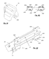
Figs. 1, 2 show, in perspective view, a possible embodiment of the step according to the invention, represented, respectively, in a retracted configuration or rest position and a working or extracted position; -
Fig. 3 is an exploded perspective view of the step shown in the previous figures; -
Fig. 4 relates to an enlarged detail, marked with the letter A inFig.3 , and represented in a perspective view; -
Figs. 5, 6 ,7 are perspective views showing the step in different operating positions, which correspond to the step retracted, the step in an intermediate position, and the step extracted;Figs. 5 and 6 comprise a detail in enlarged scale; -
Figs. 8, 9 are two perspective views of a first lever or crank usable in the step of the invention; -
Figs. 10, 11, 12 are two perspective views and a plan view of a second lever or connecting rod that can be used for making the step of the invention; -
Fig. 13 is a perspective view of a snap lock pin that can be used for making the step of the invention; -
Fig. 14 is a side view of a toothed wheel of the device according to the invention shown in the previous figures; -
Fig.15 is a perspective view of a grooved shaft of the device according to the invention shown in the previous figures; -
Figs. 16, 17 ,18, 19 are perspective views relating to components usable in the step according to the invention; in particular,Fig. 16 shows an extruded profile defining a guide,Fig. 17 shows a sliding pad,Fig. 18 shows a support element,Fig. 19 shows a flank of the tread, to which it is fixed the sliding pad ofFig. 17 and which is disposed in abutment on the element ofFig. 18 ; -
Fig. 20 is a schematic plan view, with parts removed, showing the interaction between the guide element ofFig. 16 and the pad ofFig.17 ; -
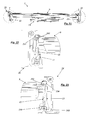
Fig. 21 is a schematic front view, with parts removed of the present step; -
Figs. 22, 23 are schematic cross-section views with parts removed of the details marked D and E inFig.21 ; -
Figs. 24, 25 represent a further example of embodiment of the motor means of the present step. In the drawings, the overall structure which forms the retractable step has been marked with thereference numeral 1; as shown inFigs. 1 and 2 , the step includes atread 2, retractable with respect to a housing body 3that encloses the motor and transmission means. In a manner known per se, and therefore not specifically described, thewhole set 1 is stably associated to the vehicle, by fixing the body (3) to the frame of the latter in the chosen position. - The
housing body 3 comprises alower base 28, provided with arear bottom part 28A, twoflanks 26, anupper cover 31, and afront closing wall 29, open and shaped so as to allow the passage of the tread through it. The tread in this example is composed of twoparts - The tread is closed at the bottom by a
bottom cover surface 30. Twoside plates 25 are associated to thetread 9, by means ofscrews 10. Thereference numeral 10 will be used even for screws arranged in other positions. - On the distal portion of each
side plate 25 is applied a cover plate (11 and 12, respectively to the right and to the left inFig.3 ). The proximal part of eachside plate 25 is fixed to asliding pad 23, that can be made of plastic material. - The
sliding pad 23 is provided with sliding portions destined to be in contact with corresponding portions of theflanks 26 of the container body, as described below. On its top part, thesliding pad 23 is provided with twoappendixes 234 that have a convex shape on the the top side, this side being destined to slide in acorresponding seat 261 of theflank 26; inferiorly, thesliding pad 23 is provided with twoappendixes 230, which are concave on thelower side 231, so as to define a concave seat that can be fitted on acorresponding convex portion 260 of theflank 26. Advantageously, in addition, thelower extension 230 of thesliding pad 23 has a discontinuity on its lower side, thus defining atooth 233 with twoopen parts 232 at both its sides to eliminate or at least drastically reduce the possible accumulation of dirt and/or debris in the sliding area. In other words, the body defined by theportion 260 of theflank 26 is not completely covered, but said portion is only partially covered, so as to form a discharge route through which dirt can exit without accumulating. In the schematic view ofFig. 20 it is possible to note that along the longitudinal direction of thelower appendix 230, that is, along a direction corresponding to the sliding direction, theteeth 233 are arranged offset on the opposite sides of thebody 260. In this way, it is ensured the guide of thesliding pad 23 when it slides along thebody 260, but the opposite sides of thesame body 260 are not completely covered by saidappendix 230. - Therefore, each of the
side plates 25 of thetread 9, provided with therespective pad 23, can slide along the direction of movement of the step along the guides defined by theflanks 26 of thecontainer body 3. In practice, inside the profiles that constitute theflanks 26 of thebody 3, there is a seat for thesliding pads 23 that (as particularly shown inFig. 20 ) inferiorly are fitted on the complementaryshaped projection 260 and, on the upper side, are inserted in theseat 261 that is complementary shaped with respect toappendix 234 of thesliding pad 23. - At the distal (or front) part of the
sides 26 of thecontainer body 3 it is fixed thesupport element 22. Thesupport element 22 has alower groove 221 which is destined to be coupled with theprotrusion 260 of thesidewalls 26 and is superiorly provided with anopen channel 220, intended to receive the lower edge of thecorresponding flank 25 of thetread tread container body 3 because the same tread is provided with theside plates 25 that slide in thecorresponding flanks 26 thanks to the presence of thesliding pads 23 and thesupport elements 22. - In the proximal or internal part of the
tread locking snap pins 24. Thepin 24 is formed by a body (realizable in plastic material) substantially cylindrical provided with anend 240 in which there is a hook which temporarily and elastically reduces its overall dimensions when it is introduced in a hole dimensioned to receive it. - Each of the
pins 24 is intended to pass through acorresponding hole 180 presented at a first end by a connectingrod 18, forming a link between the connectingrod 18 and the tread, allowing the rotation of the same connectingrod 18 about the axis defined by thepin 24. At the opposite end, the connectingrod 18 is provided with acoupling element 181, constituted by a cylindrical body projecting axially from the connecting rod and having aradial appendix 182. The outer face of thecoupling element 181 is therefore represented by a circular shape provided with aradial tooth 182. The shape of the connectingrods 18 is substantially rectilinear, with a bent part, according to the angle indicated by α in the drawings, at the ends which support thecoupling elements 181. In particular, these ends are turned towards the inside when the two connecting rods are assembled; in practice, when the connectingrods 18 are mounted, the respective bent parts are directed towards each other. - The
coupling element 181 is intended to pass through a corresponding slottedhousing 200 provided at a first end of a lever or crank 20. Thecrank 20 is provided, at the opposite end, with a through-hole 201. On one face of thecrank 20, in correspondence of thehole 201, there is provided agrooved seat 202 shaped complementary with a toothed wheel as further described in the following. - In practice, the two
cranks 20 are pivoted to the connectingrods 18, so as to be rotatable with respect to the latter, being able to rotate about the axis defined by thecoupling element 181. In addition, one of the twocranks 20 is provided with atooth 203 adapted to interfere with alimit switch 5 as described below. - The
step 1 further comprises a casing formed by two half-shells - The presence of the casing determines a considerable advantage for the protection of the system for moving the step against dirt and moisture; furthermore, it is very useful during the assembly operations because it makes it possible to realize the retractable step complete of all components of the moving system in its interior, without the risk that one or more components disengage during transport and mounting of the step on the vehicle. In addition, once the moving system is realized, completed with the casing, the same system can be applied to the step in a single operation.
- The lower half-
shell 13 is provided with threecylindrical supports toothed wheels 14 are rotatably fitted on the cylindrical supports 130 and 131 , said wheels being identical to each other and having afirst toothing 140 which extends over the entire contour of the wheel, and a second set ofteeth 141, of smaller diameter than the first, arranged on a different plane (an upper plane in the drawings) and so shaped as to be complementary to thegroove 202 of thecrank 20 which, therefore, can be easily connected to the same toothed wheel. - On the
cylindrical support 132 it is rotatably fitted apinion 15, provided with an internal toothing and an external toothing. The internal toothing of thepinion 15 is shaped in a complementary manner in respect to the toothing of agrooved motor shaft 16 driven in rotation by amotor 35. The external toothing is suitable to mesh with theexternal teeth 140 of one of thewheels 14. - The
supports wheels 14 mesh with each other and thepinion 15 engages only one of the two wheels. Referring to the drawings, in particular toFig.4 , the distance DB between thesupport 130 and thesupport 132 will be greater than the value of the distance DA between thesupport 131 and thesupport 132, so that thewheel 14 disposed on the right is engaged by thepinion 13 and transmits the motion to thewheel 14 arranged on the left. In this way, a rotation of thepinion 15 corresponds to opposite rotations of the twotoothed wheels 14; for instance, again with reference to the position ofFigure 4 , the clockwise rotation of thepinion 15 corresponds to a counterclockwise rotation of theright wheel 14 meshed directly to it and a clockwise rotation of theleft wheel 14 which is meshed with the wheel positioned on the right. - The upper half-
shell 17 is provided with a through hole for the passage of themotor shaft 16 and with two through holes, through which pass the second sets ofteeth 141 of thetoothed wheels 14. Thegrooved shaft 16 is driven by themotor 35 which is provided with a housing coverage so as to cover the relative hole. In correspondence with the holes provided for thecentral parts 141 of thewheels 14 are arranged the ends of thecranks 20 which rotate as the same wheels because theteeth 141 are stably inserted in thegrooved seats 202. - The upper half-
shell 17 has arear cavity 170 intended to accommodate amicro-switch 5 adapted to detect the positioning of the retractable step by controlling the end-stroke position of thecrank 203 mentioned above. In practice, when the step is in the rest position, i.e. when thetread containment body 3, each crank 20 is located in a position substantially parallel to the direction of displacement of the tread. In this way, the rotation of one of the cranks 20 (the one arranged on the left inFigure 7 ) brings thetooth 203 to interfere with themovable element 50 of themicro-switch 5. Theswitch 5 is within the protection cover to avoid bad contacts and/or malfunction. - The step is also provided with release means that allow to bring the step in the retracted position in case of malfunctions. As can be seen from the drawings, a
spring 34 pushes down themotor shaft 16 so as to stabilise the connection motor 35 - drive shaft 16 - pinion 15 -gear wheels 14. The lower half-shell is provided with ahole 133, which can be kept closed by an easily removable cap (not shown); through thehole 133 it is possible to access to thepinion 15, making it slide axially with respect to themotor shaft 16 and thus decoupling the motor from thegear wheels 14. This operation can be executed, for example, using a screw or other suitable tool to move upwards (see the direction of the arrow F) thepinion 15, thus disengaging it from thewheel 14 to which it is normally engaged. Once thetoothed wheels 14 are disconnected from the motor, it is possible to move the step also manually to bring it back into the rest or closed position. When the step is closed, it is possible to reconnect the toothed wheels to the motor to lock the step. - In
Figs. 5-7 are shown some configurations of thestep 1 of the invention during the opening or the extraction of thetread 9 from thecontainer body 3. In these figures theupper cover 31 is not represented to show the inside of the device. -
Fig. 5 shows the closed position, that is, the retracted configuration. In this configuration, thetread body 3; thecranks 20 and the connectingrods 18 are in the position of maximum retraction, i.e. each crank 20 is arranged substantially parallel to the direction of movement of the tread and the corresponding connectingrod 18 forms a small angle with it because of its slightly bent portion. - When the
motor 35 is activated, the rotation of thetoothed wheels 14 determines the corresponding rotation of thecranks 20 directly connected to them. The displacement of thetread 9, thanks to said angle between the connecting rods and cranks, requires a relatively limited power from the motor, thanks to the favorable gear ratio. - When the sliding step, passing through the intermediate position shown in
Figure 6 , completes its run, it arrives at the fully extended configuration. In this configuration, thecranks 20 have performed a rotation of about 180° bringing the connectingrods 18 in a position of maximum opening/ xtension that is advantageous for the subsequent operation of retraction of the step. In fact, thanks to the aforementioned bent portion of the connectingrods 18, the latter are not arranged on an ideal extension of the cranks but form with the latter an angle that facilitates the working of the motor in the phase of return to the initial position. Advantageously, some elements such as, for example, thetoothed wheels 14, thepinion 15, thegrooved shaft 16, the slidingpads 23, thesupport elements 22, as well as the connectingrods 18 and thecranks 20, can be made in plastic material of the so-called self-lubricating; for example, it can be used a resin reinforced with glass fiber. This eliminates the need to grease the geared or sliding areas; the absence of grease within the device prevents dirt and possible debris to adhere to the grease as instead occurs with greased components. -
Figs.24 and 25 show another embodiment of the system described above, in which thetoothed wheels 14 do not mesh with each other but the firsttoothed wheel 14 meshes with thepinion 15 as in the previous example, while the secondtoothed wheel 14 meshes with an idle sprocket RF interposed between thepinion 15 and the secondtoothed wheel 14. Such solution allows to space from each other the rotation axes of thetoothed wheels 14 without having to increase their diameter and, thus, it is possible to move wider steps whilst ensuring the symmetry of the forces exerted on the tread. In addition, since in this case thetoothed wheels 14 do not mesh with each other directly, when the connection of the same gear wheels with themotor shaft 16 is interrupted as mentioned before, it is possible to move the step in the retracted configuration also if it is manually pushed asymmetrically. - Naturally, the invention is not limited to what has beend described and illustrated, but may be greatly varied as regards the nature and arrangement of the materials used, without departure from the inventive teaching set forth above and hereinafter claimed.
Claims (12)
- Retractable step comprising a tread (9, 90) which slides bi-directionally along a guide (26) with corresponding sliding means, the tread (9, 90) being driven by motor means comprising an electric motor (35) to which it is connected by means of a mechanical transmission (14, 15, 16), so as to be disposed in a first retracted configuration in which the tread is in a corresponding housing body (3) and in a second extracted configuration in which the tread protrudes from said housing body, the guide (26) being arranged on two sides of said housing body (3), characterized in that it is provided with means for unlocking said transmission means (15, 16) adapted to release the connection with the said motor means.
- Step according to claim 1, characterized in that said transmission means (15, 16) comprise a pinion (15) driven by a grooved shaft (16) which in turn is connected to the motor means (35) and gears (14) connected with the pinion (15), said unlocking means being adapted to disengage the pinion (15) from said gears (14).
- Step according to claim 1, characterized in that said transmission means (15, 16) are contained within a casing (13, 17), said unlocking means being activated through an access opening (133) provided by said casing (13, 17).
- Step according to claims 2 and 3, characterized in that between said pinion (15) and said grooved shaft (16) there is a spring (34).
- Step according to any of the preceding claims, wherein the guide (26) is arranged on two sides of said housing body (3), characterized in that said sliding means comprise a body (260) provided by said guide (26) and having a profile that is complementary coupable with a sliding pad (23) integral with the tread (9, 90), the contact between said body (260) and the sliding pad (23) occurring on a discontinuous contact surface t, said contact surface having a predetermined number of discontinuities through which possible accumulations of dirt formed between the same sliding pad (23) and the body (260) can flow out.
- Step according to claim 5, characterized in that said discontinuities are provided on the sliding pad (23).
- Step according to claim 6, characterized in that said sliding pad (23) is provided with base portions or appendixes (230), whose lower face (231) is concave, defining a seat apt to be fitted on a corresponding convexity of said body (260), said appendixes (230) having a lower discontinuity that forms a series of teeth (233) arranged offset in respect to two opposite sides of the body (260).
- Step according to claim 3, characterized in that said casing (13, 17) is composed of two parts.
- Step according to one of the preceding claims, characterized in that said transmission means comprise a gear train (16, 15, 14) connected upstream to the motor means (35) and downstream to a pair of doubled levers (18, 20), one of said levers or connecting rod (18) being substantially arcuate, so that, when the step is in a position of end of stroke, or must be moved to return to the previous configuration, the same connecting rod (18) is disposed on a line not coinciding with that of the other corresponding lever or crank (20), thus determining an advantageous power request given the angle between the two levers (18, 20).
- Step according to one of the preceding claims, characterized in that said transmission means, as well as said sliding pad (23), are made of plastic material with a low coefficient of friction, of the self-lubricating type.
- Step according to one of the preceding claims, characterized in that said motor means (35) are provided with a limit sensor (5) contained at least partially in a protective casing (13, 17).
- Step according to one of the preceding claims, characterized in that it is mounted on a camper van or similar vehicle.
Applications Claiming Priority (1)
| Application Number | Priority Date | Filing Date | Title |
|---|---|---|---|
| ITFI2014U000056U ITFI20140056U1 (en) | 2014-10-01 | 2014-10-01 | REMOVABLE STEP. |
Publications (2)
| Publication Number | Publication Date |
|---|---|
| EP3002157A2 true EP3002157A2 (en) | 2016-04-06 |
| EP3002157A3 EP3002157A3 (en) | 2016-06-22 |
Family
ID=54541925
Family Applications (1)
| Application Number | Title | Priority Date | Filing Date |
|---|---|---|---|
| EP15184593.0A Withdrawn EP3002157A3 (en) | 2014-10-01 | 2015-09-10 | Extractable step |
Country Status (2)
| Country | Link |
|---|---|
| EP (1) | EP3002157A3 (en) |
| IT (1) | ITFI20140056U1 (en) |
Cited By (20)
| Publication number | Priority date | Publication date | Assignee | Title |
|---|---|---|---|---|
| US9522634B1 (en) | 2015-06-05 | 2016-12-20 | Lund Motion Products, Inc. | Horizontal retractable vehicle step |
| US9944231B2 (en) | 2006-10-27 | 2018-04-17 | Lund Motion Products, Inc. | Retractable vehicle step |
| US10077016B2 (en) | 2015-06-05 | 2018-09-18 | Lund Motion Products, Inc. | Retractable step and side bar assembly for raised vehicle |
| US10183624B2 (en) | 2001-10-16 | 2019-01-22 | Lund Motion Products, Inc. | Retractable vehicle step |
| US10391944B2 (en) | 2013-09-27 | 2019-08-27 | Lund, Inc. | Modular rail and step system |
| US10493920B2 (en) | 2006-10-27 | 2019-12-03 | Lund Motion Products, Inc. | Retractable vehicle step |
| US10618472B2 (en) | 2015-08-04 | 2020-04-14 | T-Max (Hangzhou) Technology Co., Ltd. | Vehicle and vehicle step apparatus with multiple drive motors |
| US10682960B2 (en) | 2018-07-20 | 2020-06-16 | T-Max (Hangzhou) Technology Co., Ltd. | Vehicle, running board assembly and drive assembly for running board |
| CN113370785A (en) * | 2021-05-26 | 2021-09-10 | 上海高仙自动化科技发展有限公司 | Telescopic pedal structure and sweeping robot |
| US11198394B2 (en) | 2018-07-20 | 2021-12-14 | T-Max (Hangzhou) Technology Co., Ltd. | Vehicle running board apparatus and retractable device thereof |
| US11376918B2 (en) | 2019-03-11 | 2022-07-05 | T-Max (Hangzhou) Technology Co., Ltd. | Adjustment device, adjustor and shock absorber |
| US11414017B2 (en) | 2019-03-05 | 2022-08-16 | T-Max (Hangzhou) Technology Co., Ltd. | Vehicle step apparatus and vehicle |
| JP2023009848A (en) * | 2021-07-08 | 2023-01-20 | トーシンテック株式会社 | Storable auxiliary step for vehicle |
| US11577653B2 (en) | 2020-05-11 | 2023-02-14 | T-Max (Hangzhou) Technology Co., Ltd. | Step apparatus for vehicle and vehicle |
| US11584387B2 (en) | 2019-09-16 | 2023-02-21 | T-Max (Hangzhou) Technology Co., Ltd. | Step apparatus for vehicle and vehicle |
| US11590897B2 (en) | 2020-05-11 | 2023-02-28 | T-Max (Hangzhou) Technology Co., Ltd. | Step apparatus for vehicle and vehicle |
| CN116424225A (en) * | 2023-03-29 | 2023-07-14 | 浙江颢屹汽车技术有限公司 | Rotary telescopic electric stepping mechanism |
| US11881063B2 (en) | 2019-02-20 | 2024-01-23 | T-Max (Hangzhou) Technology Co., Ltd. | Management apparatus for a vehicle device, vehicle and server |
| US11926286B2 (en) | 2011-10-31 | 2024-03-12 | Lund Motion Products, Inc. | Retractable vehicle step |
| US12202438B2 (en) | 2021-04-16 | 2025-01-21 | Lund Motion Products, Inc. | Retractable vehicle step |
Citations (1)
| Publication number | Priority date | Publication date | Assignee | Title |
|---|---|---|---|---|
| EP1393977A1 (en) | 2002-08-29 | 2004-03-03 | Omnistor Accessories, naamloze vennootschap | Extending step |
Family Cites Families (6)
| Publication number | Priority date | Publication date | Assignee | Title |
|---|---|---|---|---|
| US5305486A (en) * | 1993-06-24 | 1994-04-26 | Wheelers Manufacturing, Inc. | Vehicle passenger boarding system |
| US6102648A (en) * | 1997-09-05 | 2000-08-15 | Ricon Corporation | Driving mechanism for vehicle lifts |
| US7527467B2 (en) * | 2003-01-29 | 2009-05-05 | The Braun Corporation | Retractable ramp system for a mobility vehicle |
| FR2939735A1 (en) * | 2008-12-12 | 2010-06-18 | Faiveley Transp Tours | DEPLOYABLE DEVICE FOR ACCESSING A VEHICLE |
| EP2390142B1 (en) * | 2010-05-31 | 2013-07-31 | Hübner Transportation GbmH | Device for extendible holder for a ramp |
| KR101262910B1 (en) * | 2012-08-27 | 2013-05-09 | 황성공업 주식회사 | Electric step apparatus |
-
2014
- 2014-10-01 IT ITFI2014U000056U patent/ITFI20140056U1/en unknown
-
2015
- 2015-09-10 EP EP15184593.0A patent/EP3002157A3/en not_active Withdrawn
Patent Citations (1)
| Publication number | Priority date | Publication date | Assignee | Title |
|---|---|---|---|---|
| EP1393977A1 (en) | 2002-08-29 | 2004-03-03 | Omnistor Accessories, naamloze vennootschap | Extending step |
Cited By (46)
| Publication number | Priority date | Publication date | Assignee | Title |
|---|---|---|---|---|
| US10322677B1 (en) | 2001-02-15 | 2019-06-18 | Lund Motion Products, Inc. | Retractable vehicle step |
| US10759349B2 (en) | 2001-02-15 | 2020-09-01 | Lund Motion Products, Inc. | Retractable vehicle step |
| US10183624B2 (en) | 2001-10-16 | 2019-01-22 | Lund Motion Products, Inc. | Retractable vehicle step |
| US10596971B2 (en) | 2001-10-16 | 2020-03-24 | Lund Motion Products, Inc. | Retractable vehicle step |
| US11279290B2 (en) | 2001-10-16 | 2022-03-22 | Lund Motion Products, Inc. | Retractable vehicle step |
| US10676031B2 (en) | 2006-10-27 | 2020-06-09 | Lund Motion Products, Inc. | Retractable vehicle step |
| US9944231B2 (en) | 2006-10-27 | 2018-04-17 | Lund Motion Products, Inc. | Retractable vehicle step |
| US11964629B2 (en) | 2006-10-27 | 2024-04-23 | Lund Motion Products, Inc. | Retractable vehicle step |
| US10493920B2 (en) | 2006-10-27 | 2019-12-03 | Lund Motion Products, Inc. | Retractable vehicle step |
| US11173845B2 (en) | 2006-10-27 | 2021-11-16 | Lund Motion Products, Inc. | Retractable vehicle step |
| US11926286B2 (en) | 2011-10-31 | 2024-03-12 | Lund Motion Products, Inc. | Retractable vehicle step |
| US10391944B2 (en) | 2013-09-27 | 2019-08-27 | Lund, Inc. | Modular rail and step system |
| US10604077B2 (en) | 2013-09-27 | 2020-03-31 | Lund, Inc. | Modular rail and step system |
| US10821903B2 (en) | 2013-09-27 | 2020-11-03 | Lund, Inc. | Modular rail and step system |
| US11260798B2 (en) | 2015-06-05 | 2022-03-01 | Lund Motion Products, Inc. | Horizontal retractable vehicle step |
| US11713012B2 (en) | 2015-06-05 | 2023-08-01 | Lund Motion Products, Inc. | Retractable step and side bar assembly for raised vehicle |
| US10773670B2 (en) | 2015-06-05 | 2020-09-15 | Lund Motion Products, Inc. | Retractable step and side bar assembly for raised vehicle |
| US12291157B2 (en) | 2015-06-05 | 2025-05-06 | Lund Motion Products, Inc. | Retractable step and side bar assembly for raised vehicle |
| US10195997B2 (en) | 2015-06-05 | 2019-02-05 | Lund Motion Products, Inc. | Horizontal retractable vehicle step |
| US11180100B2 (en) | 2015-06-05 | 2021-11-23 | Lund Motion Products, Inc. | Retractable step and side bar assembly for raised vehicle |
| US11999309B2 (en) | 2015-06-05 | 2024-06-04 | Lund Motion Products, Inc. | Retractable step and side bar assembly for raised vehicle |
| US12090958B2 (en) | 2015-06-05 | 2024-09-17 | Lund Motion Products, Inc. | Horizontal retractable vehicle step |
| US9522634B1 (en) | 2015-06-05 | 2016-12-20 | Lund Motion Products, Inc. | Horizontal retractable vehicle step |
| US10077016B2 (en) | 2015-06-05 | 2018-09-18 | Lund Motion Products, Inc. | Retractable step and side bar assembly for raised vehicle |
| US12115940B2 (en) | 2015-08-04 | 2024-10-15 | T-Max (Hangzhou) Technology, Co., Ltd. | Vehicle and vehicle step apparatus with multiple drive motors |
| US10618472B2 (en) | 2015-08-04 | 2020-04-14 | T-Max (Hangzhou) Technology Co., Ltd. | Vehicle and vehicle step apparatus with multiple drive motors |
| US11208043B2 (en) | 2015-08-04 | 2021-12-28 | T-Max (Hangzhou) Technology Co., Ltd. | Vehicle and vehicle step apparatus with multiple drive motors |
| US11021108B2 (en) | 2015-08-04 | 2021-06-01 | T-Max (Hangzhou) Technology Co., Ltd. | Vehicle and vehicle step apparatus with multiple drive motors |
| US12017614B2 (en) | 2018-07-20 | 2024-06-25 | T-Max (Hangzhou) Technology Co., Ltd. | Vehicle, running board assembly and drive assembly for running board |
| US11577654B2 (en) | 2018-07-20 | 2023-02-14 | T-Max (Hangzhou) Technology Co., Ltd. | Vehicle, running board assembly and drive assembly for running board |
| US11318889B2 (en) | 2018-07-20 | 2022-05-03 | T-Max (Hangzhou) Technology Co., Ltd. | Vehicle, running board assembly and drive assembly for running board |
| US11702012B2 (en) | 2018-07-20 | 2023-07-18 | T-Max (Hangzhou) Technology Co., Ltd. | Vehicle running board apparatus and retractable device thereof |
| US11292390B2 (en) | 2018-07-20 | 2022-04-05 | T-Max (Hangzhou) Technology Co., Ltd. | Vehicle, running board assembly and drive assembly for running board |
| US11198394B2 (en) | 2018-07-20 | 2021-12-14 | T-Max (Hangzhou) Technology Co., Ltd. | Vehicle running board apparatus and retractable device thereof |
| US10682960B2 (en) | 2018-07-20 | 2020-06-16 | T-Max (Hangzhou) Technology Co., Ltd. | Vehicle, running board assembly and drive assembly for running board |
| US11881063B2 (en) | 2019-02-20 | 2024-01-23 | T-Max (Hangzhou) Technology Co., Ltd. | Management apparatus for a vehicle device, vehicle and server |
| US11414017B2 (en) | 2019-03-05 | 2022-08-16 | T-Max (Hangzhou) Technology Co., Ltd. | Vehicle step apparatus and vehicle |
| US11376918B2 (en) | 2019-03-11 | 2022-07-05 | T-Max (Hangzhou) Technology Co., Ltd. | Adjustment device, adjustor and shock absorber |
| US11584387B2 (en) | 2019-09-16 | 2023-02-21 | T-Max (Hangzhou) Technology Co., Ltd. | Step apparatus for vehicle and vehicle |
| US11577653B2 (en) | 2020-05-11 | 2023-02-14 | T-Max (Hangzhou) Technology Co., Ltd. | Step apparatus for vehicle and vehicle |
| US11590897B2 (en) | 2020-05-11 | 2023-02-28 | T-Max (Hangzhou) Technology Co., Ltd. | Step apparatus for vehicle and vehicle |
| US12202438B2 (en) | 2021-04-16 | 2025-01-21 | Lund Motion Products, Inc. | Retractable vehicle step |
| CN113370785A (en) * | 2021-05-26 | 2021-09-10 | 上海高仙自动化科技发展有限公司 | Telescopic pedal structure and sweeping robot |
| JP2023009848A (en) * | 2021-07-08 | 2023-01-20 | トーシンテック株式会社 | Storable auxiliary step for vehicle |
| CN116424225B (en) * | 2023-03-29 | 2023-11-07 | 浙江颢屹汽车技术有限公司 | Rotary telescopic electric stepping mechanism |
| CN116424225A (en) * | 2023-03-29 | 2023-07-14 | 浙江颢屹汽车技术有限公司 | Rotary telescopic electric stepping mechanism |
Also Published As
| Publication number | Publication date |
|---|---|
| EP3002157A3 (en) | 2016-06-22 |
| ITFI20140056U1 (en) | 2016-04-01 |
Similar Documents
| Publication | Publication Date | Title |
|---|---|---|
| ITFI20140056U1 (en) | REMOVABLE STEP. | |
| CN105584332B (en) | Sliding motor vehicle door arrangement for vehicle | |
| EP3332078B1 (en) | Hinge device with long reciprocating stroke of a front panel | |
| US8243137B2 (en) | Device for opening a vehicle lock and for capturing an image on the exterior of the vehicle | |
| US9676446B2 (en) | Bicycle derailleur gear, particularly a front derailleur gear, with improved reliability | |
| CN106218369B (en) | Sliding door apparatus for vehicle | |
| CN106030013B (en) | Door Snap device | |
| FR3024173A1 (en) | HANDLE ASSEMBLY FOR A MOTOR VEHICLE AND OPENING COMPRISING SUCH A HANDLE ASSEMBLY | |
| WO2008089547A1 (en) | Power dual action rocker board | |
| JP5902303B2 (en) | Synchronizer for moving furniture parts | |
| FR3023865A1 (en) | HANDLE ASSEMBLY FOR A MOTOR VEHICLE AND OPENING COMPRISING SUCH A HANDLE ASSEMBLY | |
| DE102013109914A1 (en) | Cover flap arrangement for a handle arrangement of a motor vehicle door | |
| EP3002156A2 (en) | Retractable step | |
| FR3001488A1 (en) | Locking assembly for locking and unlocking e.g. petrol supply access trap door, articulated at door frame of e.g. lorry, has housing comprising passage formed, so that locking element in unlocking position crosses passage to leave housing | |
| KR101526851B1 (en) | Impact absorbing device for vehicle door | |
| EP2799652A1 (en) | Sliding gate | |
| RU2014119910A (en) | ELECTRIC ROTARY ACTUATOR FOR ENTRANCE AND EXIT DEVICE, IN PARTICULAR FOR DOOR | |
| IT201900003557A1 (en) | CARIGLIONE HANDLE FOR WINDOWS | |
| IT201900013797A1 (en) | DOOR LOCK | |
| RU69903U1 (en) | DEVICE FOR OPENING AND CLOSING A SLIDING DOOR OF A VEHICLE | |
| KR101374524B1 (en) | Manual Lumber Support Device of Seat | |
| KR20210006077A (en) | Scaffolding for special purpose truck | |
| KR100471127B1 (en) | An opening and shutting device for door of freight car | |
| RU62632U1 (en) | DEVICE FOR OPENING AND CLOSING A SLIDING DOOR OF A VEHICLE | |
| FR2925099A3 (en) | MOTOR VEHICLE SAFE DOOR ARRANGEMENT |
Legal Events
| Date | Code | Title | Description |
|---|---|---|---|
| PUAI | Public reference made under article 153(3) epc to a published international application that has entered the european phase |
Free format text: ORIGINAL CODE: 0009012 |
|
| AK | Designated contracting states |
Kind code of ref document: A2 Designated state(s): AL AT BE BG CH CY CZ DE DK EE ES FI FR GB GR HR HU IE IS IT LI LT LU LV MC MK MT NL NO PL PT RO RS SE SI SK SM TR |
|
| AX | Request for extension of the european patent |
Extension state: BA ME |
|
| PUAL | Search report despatched |
Free format text: ORIGINAL CODE: 0009013 |
|
| AK | Designated contracting states |
Kind code of ref document: A3 Designated state(s): AL AT BE BG CH CY CZ DE DK EE ES FI FR GB GR HR HU IE IS IT LI LT LU LV MC MK MT NL NO PL PT RO RS SE SI SK SM TR |
|
| AX | Request for extension of the european patent |
Extension state: BA ME |
|
| RIC1 | Information provided on ipc code assigned before grant |
Ipc: B60R 3/02 20060101AFI20160513BHEP |
|
| STAA | Information on the status of an ep patent application or granted ep patent |
Free format text: STATUS: THE APPLICATION IS DEEMED TO BE WITHDRAWN |
|
| 18D | Application deemed to be withdrawn |
Effective date: 20161223 |