EP3002103A2 - Plastic welding device and plastic welding method for same - Google Patents
Plastic welding device and plastic welding method for same Download PDFInfo
- Publication number
- EP3002103A2 EP3002103A2 EP15185694.5A EP15185694A EP3002103A2 EP 3002103 A2 EP3002103 A2 EP 3002103A2 EP 15185694 A EP15185694 A EP 15185694A EP 3002103 A2 EP3002103 A2 EP 3002103A2
- Authority
- EP
- European Patent Office
- Prior art keywords
- tool
- component
- welding
- plastic
- preheating
- Prior art date
- Legal status (The legal status is an assumption and is not a legal conclusion. Google has not performed a legal analysis and makes no representation as to the accuracy of the status listed.)
- Granted
Links
- 238000004023 plastic welding Methods 0.000 title claims abstract description 108
- 238000000034 method Methods 0.000 title claims description 61
- 238000003466 welding Methods 0.000 claims abstract description 132
- 239000002131 composite material Substances 0.000 claims abstract description 46
- 229920003023 plastic Polymers 0.000 claims description 22
- 239000004033 plastic Substances 0.000 claims description 22
- 238000003860 storage Methods 0.000 claims description 18
- 230000004888 barrier function Effects 0.000 claims description 8
- 238000010438 heat treatment Methods 0.000 claims description 5
- GNFTZDOKVXKIBK-UHFFFAOYSA-N 3-(2-methoxyethoxy)benzohydrazide Chemical compound COCCOC1=CC=CC(C(=O)NN)=C1 GNFTZDOKVXKIBK-UHFFFAOYSA-N 0.000 claims description 3
- 239000000969 carrier Substances 0.000 claims 1
- 230000008569 process Effects 0.000 description 13
- 230000008901 benefit Effects 0.000 description 10
- 238000004519 manufacturing process Methods 0.000 description 6
- 238000005516 engineering process Methods 0.000 description 4
- YTAHJIFKAKIKAV-XNMGPUDCSA-N [(1R)-3-morpholin-4-yl-1-phenylpropyl] N-[(3S)-2-oxo-5-phenyl-1,3-dihydro-1,4-benzodiazepin-3-yl]carbamate Chemical compound O=C1[C@H](N=C(C2=C(N1)C=CC=C2)C1=CC=CC=C1)NC(O[C@H](CCN1CCOCC1)C1=CC=CC=C1)=O YTAHJIFKAKIKAV-XNMGPUDCSA-N 0.000 description 2
- FGUUSXIOTUKUDN-IBGZPJMESA-N C1(=CC=CC=C1)N1C2=C(NC([C@H](C1)NC=1OC(=NN=1)C1=CC=CC=C1)=O)C=CC=C2 Chemical compound C1(=CC=CC=C1)N1C2=C(NC([C@H](C1)NC=1OC(=NN=1)C1=CC=CC=C1)=O)C=CC=C2 FGUUSXIOTUKUDN-IBGZPJMESA-N 0.000 description 1
- 230000001133 acceleration Effects 0.000 description 1
- 230000015572 biosynthetic process Effects 0.000 description 1
- 230000008859 change Effects 0.000 description 1
- 230000000295 complement effect Effects 0.000 description 1
- 238000010276 construction Methods 0.000 description 1
- 239000002537 cosmetic Substances 0.000 description 1
- 230000001419 dependent effect Effects 0.000 description 1
- 230000000694 effects Effects 0.000 description 1
- 230000007246 mechanism Effects 0.000 description 1
- 230000009467 reduction Effects 0.000 description 1
- 230000000284 resting effect Effects 0.000 description 1
- 230000000717 retained effect Effects 0.000 description 1
Images


Classifications
-
- B—PERFORMING OPERATIONS; TRANSPORTING
- B29—WORKING OF PLASTICS; WORKING OF SUBSTANCES IN A PLASTIC STATE IN GENERAL
- B29C—SHAPING OR JOINING OF PLASTICS; SHAPING OF MATERIAL IN A PLASTIC STATE, NOT OTHERWISE PROVIDED FOR; AFTER-TREATMENT OF THE SHAPED PRODUCTS, e.g. REPAIRING
- B29C65/00—Joining or sealing of preformed parts, e.g. welding of plastics materials; Apparatus therefor
- B29C65/02—Joining or sealing of preformed parts, e.g. welding of plastics materials; Apparatus therefor by heating, with or without pressure
- B29C65/06—Joining or sealing of preformed parts, e.g. welding of plastics materials; Apparatus therefor by heating, with or without pressure using friction, e.g. spin welding
-
- B—PERFORMING OPERATIONS; TRANSPORTING
- B29—WORKING OF PLASTICS; WORKING OF SUBSTANCES IN A PLASTIC STATE IN GENERAL
- B29C—SHAPING OR JOINING OF PLASTICS; SHAPING OF MATERIAL IN A PLASTIC STATE, NOT OTHERWISE PROVIDED FOR; AFTER-TREATMENT OF THE SHAPED PRODUCTS, e.g. REPAIRING
- B29C65/00—Joining or sealing of preformed parts, e.g. welding of plastics materials; Apparatus therefor
- B29C65/02—Joining or sealing of preformed parts, e.g. welding of plastics materials; Apparatus therefor by heating, with or without pressure
- B29C65/14—Joining or sealing of preformed parts, e.g. welding of plastics materials; Apparatus therefor by heating, with or without pressure using wave energy, i.e. electromagnetic radiation, or particle radiation
- B29C65/1403—Joining or sealing of preformed parts, e.g. welding of plastics materials; Apparatus therefor by heating, with or without pressure using wave energy, i.e. electromagnetic radiation, or particle radiation characterised by the type of electromagnetic or particle radiation
- B29C65/1412—Infrared [IR] radiation
-
- B—PERFORMING OPERATIONS; TRANSPORTING
- B29—WORKING OF PLASTICS; WORKING OF SUBSTANCES IN A PLASTIC STATE IN GENERAL
- B29C—SHAPING OR JOINING OF PLASTICS; SHAPING OF MATERIAL IN A PLASTIC STATE, NOT OTHERWISE PROVIDED FOR; AFTER-TREATMENT OF THE SHAPED PRODUCTS, e.g. REPAIRING
- B29C65/00—Joining or sealing of preformed parts, e.g. welding of plastics materials; Apparatus therefor
- B29C65/02—Joining or sealing of preformed parts, e.g. welding of plastics materials; Apparatus therefor by heating, with or without pressure
- B29C65/14—Joining or sealing of preformed parts, e.g. welding of plastics materials; Apparatus therefor by heating, with or without pressure using wave energy, i.e. electromagnetic radiation, or particle radiation
- B29C65/1429—Joining or sealing of preformed parts, e.g. welding of plastics materials; Apparatus therefor by heating, with or without pressure using wave energy, i.e. electromagnetic radiation, or particle radiation characterised by the way of heating the interface
- B29C65/1432—Joining or sealing of preformed parts, e.g. welding of plastics materials; Apparatus therefor by heating, with or without pressure using wave energy, i.e. electromagnetic radiation, or particle radiation characterised by the way of heating the interface direct heating of the surfaces to be joined
-
- B—PERFORMING OPERATIONS; TRANSPORTING
- B29—WORKING OF PLASTICS; WORKING OF SUBSTANCES IN A PLASTIC STATE IN GENERAL
- B29C—SHAPING OR JOINING OF PLASTICS; SHAPING OF MATERIAL IN A PLASTIC STATE, NOT OTHERWISE PROVIDED FOR; AFTER-TREATMENT OF THE SHAPED PRODUCTS, e.g. REPAIRING
- B29C65/00—Joining or sealing of preformed parts, e.g. welding of plastics materials; Apparatus therefor
- B29C65/72—Joining or sealing of preformed parts, e.g. welding of plastics materials; Apparatus therefor by combined operations or combined techniques, e.g. welding and stitching
-
- B—PERFORMING OPERATIONS; TRANSPORTING
- B29—WORKING OF PLASTICS; WORKING OF SUBSTANCES IN A PLASTIC STATE IN GENERAL
- B29C—SHAPING OR JOINING OF PLASTICS; SHAPING OF MATERIAL IN A PLASTIC STATE, NOT OTHERWISE PROVIDED FOR; AFTER-TREATMENT OF THE SHAPED PRODUCTS, e.g. REPAIRING
- B29C65/00—Joining or sealing of preformed parts, e.g. welding of plastics materials; Apparatus therefor
- B29C65/78—Means for handling the parts to be joined, e.g. for making containers or hollow articles, e.g. means for handling sheets, plates, web-like materials, tubular articles, hollow articles or elements to be joined therewith; Means for discharging the joined articles from the joining apparatus
- B29C65/7858—Means for handling the parts to be joined, e.g. for making containers or hollow articles, e.g. means for handling sheets, plates, web-like materials, tubular articles, hollow articles or elements to be joined therewith; Means for discharging the joined articles from the joining apparatus characterised by the feeding movement of the parts to be joined
- B29C65/7861—In-line machines, i.e. feeding, joining and discharging are in one production line
- B29C65/7864—In-line machines, i.e. feeding, joining and discharging are in one production line using a feeding table which moves to and fro
-
- B—PERFORMING OPERATIONS; TRANSPORTING
- B29—WORKING OF PLASTICS; WORKING OF SUBSTANCES IN A PLASTIC STATE IN GENERAL
- B29C—SHAPING OR JOINING OF PLASTICS; SHAPING OF MATERIAL IN A PLASTIC STATE, NOT OTHERWISE PROVIDED FOR; AFTER-TREATMENT OF THE SHAPED PRODUCTS, e.g. REPAIRING
- B29C66/00—General aspects of processes or apparatus for joining preformed parts
- B29C66/01—General aspects dealing with the joint area or with the area to be joined
- B29C66/02—Preparation of the material, in the area to be joined, prior to joining or welding
- B29C66/024—Thermal pre-treatments
- B29C66/0242—Heating, or preheating, e.g. drying
-
- B—PERFORMING OPERATIONS; TRANSPORTING
- B29—WORKING OF PLASTICS; WORKING OF SUBSTANCES IN A PLASTIC STATE IN GENERAL
- B29C—SHAPING OR JOINING OF PLASTICS; SHAPING OF MATERIAL IN A PLASTIC STATE, NOT OTHERWISE PROVIDED FOR; AFTER-TREATMENT OF THE SHAPED PRODUCTS, e.g. REPAIRING
- B29C66/00—General aspects of processes or apparatus for joining preformed parts
- B29C66/01—General aspects dealing with the joint area or with the area to be joined
- B29C66/05—Particular design of joint configurations
- B29C66/301—Three-dimensional joints, i.e. the joined area being substantially non-flat
-
- B—PERFORMING OPERATIONS; TRANSPORTING
- B29—WORKING OF PLASTICS; WORKING OF SUBSTANCES IN A PLASTIC STATE IN GENERAL
- B29C—SHAPING OR JOINING OF PLASTICS; SHAPING OF MATERIAL IN A PLASTIC STATE, NOT OTHERWISE PROVIDED FOR; AFTER-TREATMENT OF THE SHAPED PRODUCTS, e.g. REPAIRING
- B29C66/00—General aspects of processes or apparatus for joining preformed parts
- B29C66/50—General aspects of joining tubular articles; General aspects of joining long products, i.e. bars or profiled elements; General aspects of joining single elements to tubular articles, hollow articles or bars; General aspects of joining several hollow-preforms to form hollow or tubular articles
- B29C66/51—Joining tubular articles, profiled elements or bars; Joining single elements to tubular articles, hollow articles or bars; Joining several hollow-preforms to form hollow or tubular articles
- B29C66/54—Joining several hollow-preforms, e.g. half-shells, to form hollow articles, e.g. for making balls, containers; Joining several hollow-preforms, e.g. half-cylinders, to form tubular articles
- B29C66/543—Joining several hollow-preforms, e.g. half-shells, to form hollow articles, e.g. for making balls, containers; Joining several hollow-preforms, e.g. half-cylinders, to form tubular articles joining more than two hollow-preforms to form said hollow articles
-
- B—PERFORMING OPERATIONS; TRANSPORTING
- B29—WORKING OF PLASTICS; WORKING OF SUBSTANCES IN A PLASTIC STATE IN GENERAL
- B29C—SHAPING OR JOINING OF PLASTICS; SHAPING OF MATERIAL IN A PLASTIC STATE, NOT OTHERWISE PROVIDED FOR; AFTER-TREATMENT OF THE SHAPED PRODUCTS, e.g. REPAIRING
- B29C66/00—General aspects of processes or apparatus for joining preformed parts
- B29C66/80—General aspects of machine operations or constructions and parts thereof
- B29C66/83—General aspects of machine operations or constructions and parts thereof characterised by the movement of the joining or pressing tools
- B29C66/832—Reciprocating joining or pressing tools
- B29C66/8322—Joining or pressing tools reciprocating along one axis
-
- B—PERFORMING OPERATIONS; TRANSPORTING
- B29—WORKING OF PLASTICS; WORKING OF SUBSTANCES IN A PLASTIC STATE IN GENERAL
- B29C—SHAPING OR JOINING OF PLASTICS; SHAPING OF MATERIAL IN A PLASTIC STATE, NOT OTHERWISE PROVIDED FOR; AFTER-TREATMENT OF THE SHAPED PRODUCTS, e.g. REPAIRING
- B29C66/00—General aspects of processes or apparatus for joining preformed parts
- B29C66/80—General aspects of machine operations or constructions and parts thereof
- B29C66/84—Specific machine types or machines suitable for specific applications
- B29C66/843—Machines for making separate joints at the same time in different planes; Machines for making separate joints at the same time mounted in parallel or in series
- B29C66/8432—Machines for making separate joints at the same time mounted in parallel or in series
-
- B—PERFORMING OPERATIONS; TRANSPORTING
- B29—WORKING OF PLASTICS; WORKING OF SUBSTANCES IN A PLASTIC STATE IN GENERAL
- B29C—SHAPING OR JOINING OF PLASTICS; SHAPING OF MATERIAL IN A PLASTIC STATE, NOT OTHERWISE PROVIDED FOR; AFTER-TREATMENT OF THE SHAPED PRODUCTS, e.g. REPAIRING
- B29C65/00—Joining or sealing of preformed parts, e.g. welding of plastics materials; Apparatus therefor
- B29C65/02—Joining or sealing of preformed parts, e.g. welding of plastics materials; Apparatus therefor by heating, with or without pressure
- B29C65/18—Joining or sealing of preformed parts, e.g. welding of plastics materials; Apparatus therefor by heating, with or without pressure using heated tools
- B29C65/20—Joining or sealing of preformed parts, e.g. welding of plastics materials; Apparatus therefor by heating, with or without pressure using heated tools with direct contact, e.g. using "mirror"
- B29C65/2053—Joining or sealing of preformed parts, e.g. welding of plastics materials; Apparatus therefor by heating, with or without pressure using heated tools with direct contact, e.g. using "mirror" characterised by special ways of bringing the welding mirrors into position
- B29C65/2061—Joining or sealing of preformed parts, e.g. welding of plastics materials; Apparatus therefor by heating, with or without pressure using heated tools with direct contact, e.g. using "mirror" characterised by special ways of bringing the welding mirrors into position by sliding
- B29C65/2069—Joining or sealing of preformed parts, e.g. welding of plastics materials; Apparatus therefor by heating, with or without pressure using heated tools with direct contact, e.g. using "mirror" characterised by special ways of bringing the welding mirrors into position by sliding with an angle with respect to the plane comprising the parts to be joined
-
- B—PERFORMING OPERATIONS; TRANSPORTING
- B29—WORKING OF PLASTICS; WORKING OF SUBSTANCES IN A PLASTIC STATE IN GENERAL
- B29C—SHAPING OR JOINING OF PLASTICS; SHAPING OF MATERIAL IN A PLASTIC STATE, NOT OTHERWISE PROVIDED FOR; AFTER-TREATMENT OF THE SHAPED PRODUCTS, e.g. REPAIRING
- B29C65/00—Joining or sealing of preformed parts, e.g. welding of plastics materials; Apparatus therefor
- B29C65/02—Joining or sealing of preformed parts, e.g. welding of plastics materials; Apparatus therefor by heating, with or without pressure
- B29C65/18—Joining or sealing of preformed parts, e.g. welding of plastics materials; Apparatus therefor by heating, with or without pressure using heated tools
- B29C65/20—Joining or sealing of preformed parts, e.g. welding of plastics materials; Apparatus therefor by heating, with or without pressure using heated tools with direct contact, e.g. using "mirror"
- B29C65/2053—Joining or sealing of preformed parts, e.g. welding of plastics materials; Apparatus therefor by heating, with or without pressure using heated tools with direct contact, e.g. using "mirror" characterised by special ways of bringing the welding mirrors into position
- B29C65/2084—Joining or sealing of preformed parts, e.g. welding of plastics materials; Apparatus therefor by heating, with or without pressure using heated tools with direct contact, e.g. using "mirror" characterised by special ways of bringing the welding mirrors into position by pivoting
-
- B—PERFORMING OPERATIONS; TRANSPORTING
- B29—WORKING OF PLASTICS; WORKING OF SUBSTANCES IN A PLASTIC STATE IN GENERAL
- B29C—SHAPING OR JOINING OF PLASTICS; SHAPING OF MATERIAL IN A PLASTIC STATE, NOT OTHERWISE PROVIDED FOR; AFTER-TREATMENT OF THE SHAPED PRODUCTS, e.g. REPAIRING
- B29C66/00—General aspects of processes or apparatus for joining preformed parts
- B29C66/80—General aspects of machine operations or constructions and parts thereof
- B29C66/87—Auxiliary operations or devices
- B29C66/874—Safety measures or devices
- B29C66/8742—Safety measures or devices for operators
-
- B—PERFORMING OPERATIONS; TRANSPORTING
- B29—WORKING OF PLASTICS; WORKING OF SUBSTANCES IN A PLASTIC STATE IN GENERAL
- B29L—INDEXING SCHEME ASSOCIATED WITH SUBCLASS B29C, RELATING TO PARTICULAR ARTICLES
- B29L2031/00—Other particular articles
- B29L2031/30—Vehicles, e.g. ships or aircraft, or body parts thereof
- B29L2031/3055—Cars
Definitions
- the present invention relates to a plastic welding apparatus for automatically welding at least three components and a plastic welding method for at least three components.
- Plastic welding devices usually comprise a housing with a lower tool arranged therein and an upper tool arranged therein.
- the lower tool is attached to a lifting table, whereas the upper tool is rigidly attached to an upper tool plate.
- the lifting table By means of the lifting table, the lower tool can be moved in the direction of the upper tool to weld a first component in the lower tool with a second component in the upper tool, for example by friction welding.
- plastic welding devices are used for example in the automotive industry or in medical technology. In the automotive industry, such plastic welding devices are used for the production of lights, but can also be used in the manufacture of other components or groups of components that consist of plastics or plastics. Similarly, the plastic welding apparatus can be used in the manufacture of devices and / or component groups in medical technology or in the manufacture of consumer goods.
- the procedure with the known plastic welding device is as follows. An operator first inserts a first component into the receptacle of the lower tool. He then positions a second component on the first component in the lower tool. Thereafter, the operator starts the welding process, wherein initially closes a housing opening, so that an intervention in the plastic welding device to protect the operator is no longer possible. After closing the housing, the lifting table moves with the lower tool and the components arranged thereon from an initial position in the direction of the upper tool until the second component rests in the upper tool and the lifting table and the two components are in a welding position. Now, a welding of the first component with the second component by means of friction welding. After completion of the Reibsch Strukturens moves the lift table with the lower tool and arranged therein composite of first and second component from the welding position back to the initial position. Now the housing opening is opened again and the operator can remove the composite of first and second component.
- the object of the present invention is therefore to provide a plastic welding device which enables automatic welding of at least three parts. Furthermore, a corresponding plastic welding process is to be provided.
- the inventive plastic welding device for automatically welding at least three components comprises at least one first tool on which a first component can be positioned, at least one second tool, wherein the first and the second tool are movable relative to each other to the first component with a second component welding, and at least one transfer device which is movable relative to at least one of the tools and with which automatically at least a second and / or a third component can be fed to one of the tools, so that the at least one third component with the composite of first and second component over the first and the second tool or via the first or the second tool in combination with a third tool is weldable.
- the plastic welding device is a plastic friction welding device, a plastic infrared welding device or a combination thereof.
- the plastic welding device will initially be described as a plastic friction welding device.
- the first tool is preferably arranged on a first carrier, in particular on a lifting table.
- the second tool is preferably arranged on a second carrier, in particular on an upper mounting plate.
- the first and second carrier are movable relative to each other.
- the first and second tools are movable relative to each other in such a way that at least two components can be connected to one another.
- the first carrier is rigidly arranged while the tools and components are moved relative to one another via the movement of the lifting table.
- the plastic welding device according to the invention comprises the at least one transfer device, with which the third component is automatically fed to one of the tools, as explained below.
- the third component is already stored or arranged at the beginning in the plastic welding device.
- an operator places the first component in the first tool.
- the second component is arranged by the operator on the first component.
- the operator can also arrange the second component directly in the second tool.
- the third component is arranged in a storage position in the plastic welding device by the operator. After all the components have been placed in position in the plastic welding device, the operator starts the plastic welding device.
- all or some of these initial loading steps can be performed by a robot, a loading unit or a loading and unloading unit. These and the subsequent steps of the welding process are preferably predetermined by a control device of the plastic welding device.
- first step of the lifting table With the first tool from an initial position in the direction of the second tool to a first welding position.
- an automatic centering of the first and the second component relative to one another and to the respective tool takes place prior to the complete procedure in the first welding position.
- the first and the second component are welded together by means of friction welding.
- the lift table moves from the welding position to a first intermediate position, whereby the first and second tools move away from each other.
- the intermediate position may be the starting position or any position between the first welding position and the starting position.
- the composite of welded first and second component remains in the first tool.
- the composite can also be retained in the second tool, for example mechanically or by means of negative pressure.
- the transfer device is any device with which automatically the third component can be fed from one storage position to one of the tools.
- these are movable lever and pivot mechanisms, movable tools, a robot arm or, preferably, the apparatus explained below in the detailed description.
- the transfer device is also designed as a further tool.
- the supply of the third component to the first or second tool requires that the third component has a shape or outer contour that is similar to the shape of the first or the second component.
- the third component becomes the second tool supplied, so has a shape that is designed to match or identical to the shape of the second component.
- the third component can also be deposited on the composite of first and second component in the first tool. If the third component has a shape that is identical to the first component, then the composite of the first and second component remains after welding in the second tool, so that the third component in the first tool can be automatically positioned by the transfer device.
- the lifting table travels from the first intermediate position to a second welding position, that is to say in the direction of the second tool.
- a second welding position that is to say in the direction of the second tool.
- an optional centering and / or positioning step can be performed, as described above for the first and the second component.
- the third component is aligned with the composite of the first and second component.
- the third component with the second tool and the composite of the first and second components are aligned with the first tool.
- the welding of the third component with the composite of the first and second component takes place by means of friction welding.
- the lift table moves out of the second welding position and preferably back to the initial position.
- the composite of first, second and third component is hereby optionally arranged in the first or in the second tool and is removed accordingly by the operator.
- the composite of a robot, a removal unit or a loading and unloading unit can be removed automatically.
- An advantage of the plastic welding device according to the invention is that the cycle time is reduced in comparison to a conventional plastic welding device, since the time for loading the plastic welding device with the third component is not required. This leads to a higher efficiency and thus to a cost reduction compared to conventional plastic welding devices.
- the cycle time can be further reduced if the finished composite of the first, second and third component is arranged in the second tool, since then directly loading with the first, the second and the third component can be done without first the finished composite must be removed ,
- the plastic welding device preferably has a third tool for the third component.
- the third tool is arranged adjacent to the first or second tool depending on the process.
- the third tool is disposed on the second carrier adjacent to the second tool, that is preferably on the upper mounting plate.
- the sequence of the method is identical to the method steps described above until the third component has been handed over. Instead of automatically transferring the third component to the first or the second tool, however, the third component is automatically transferred to the third tool. Furthermore, since the first tool is aligned in a first position with the second tool for establishing the first and second component assembly, the first tool must now be moved to a second position where it is aligned with the third tool. Preferably, the first tool is therefore movable on the lifting table between a first position, in which it is aligned with the second tool, and a second position, in which it is aligned with the third tool. Should the third tool be located elsewhere, then the arrangement described by way of example must change accordingly. In any case, the tool that carries or holds the composite of the first and second component must be alignable with the tool that has or holds the third component during the course of the process.
- the further method proceeds analogously to the method described above.
- an optional centering or positioning step is feasible before reaching the final welding position.
- the welding of the third component with the composite of the first and second component takes place by means of friction welding.
- the lift table moves out of the second welding position and, for example, back to the starting position.
- the composite of first, second and third component is hereby optionally arranged in the first or in the third tool and is removed accordingly by the operator.
- the composite of a robot, a removal unit or a loading and unloading unit can be removed automatically.
- An advantage of this embodiment is that at least three components of different shape are automatically welded together. Compared to a conventional plastic welding apparatus, this provides the cycle time advantage already discussed above.
- the transfer device is arranged on the first carrier, ie in particular on the lifting table, and movable between a storage position and a transfer position.
- the plastic welding device has a preheating arrangement with a first preheating device.
- the first preheating device is preferably an intra-preheating device.
- the preheating arrangement itself is movable between a rest position and a preheat position. In the preheating position, the preheating device is aligned with one of the tools, so that a component in the corresponding tool can be heated at least partially in the area to be welded.
- the preheating of the corresponding component takes place before welding to the other component or the composite. For example, the preheating takes place before the welding of the first component to the second component. alternative or in addition, the preheating also takes place before the welding of the third component with the composite of the first and second component.
- the latter now contains further method steps after the lifting table has reached the first and / or the second intermediate position.
- the method of preheating arrangement from a rest position to a preheat position, such that the at least one preheater is aligned with one of the tools.
- the preheating is brought into contact with the tool to be heated and there is an at least partial heating of the surface of the component in the tool in the area to be welded.
- the first preheating is brought back out of engagement with the component and the preheating is driven back from the preheating position in the rest position.
- An advantage of preheating is that a more visually sophisticated weld is achievable, which is particularly desirable in the automotive industry, for example in lighting applications.
- the optically more demanding weld seam or cosmetic weld seam is in particular the result of a reduced or completely inhibited formation of lint during friction welding of the preheated components.
- An additional advantage of the preheating is in particular the increased strength of the subsequent welded joint in selected plastics.
- the preheating arrangement comprises a second preheating device, which is particularly suitable or complementary to the first preheating device and which is arranged on a surface of a carrier of the preheating arrangement opposite the first preheating device.
- the preheating arrangement is freely movable in space in one embodiment. This also applies to the other components, such as tools and transfer device. This independent movement in space is briefly explained below using the example of the preheating arrangement.
- the preheating arrangement is movable along two separate axes. In this way, the preheating arrangement can be moved, for example, next to the lifting table along the first axis in the vertical direction and along the second axis in the horizontal direction between the lifting table and upper mounting plate movable.
- the preheating arrangement is structurally connected to the lifting table, so that a vertical movement can be realized together with the lifting table.
- the second component is already arranged in the second tool and the lifting table is either in the initial position or in a second intermediate position. Both the initial position and the second intermediate position provide a distance between the first and second tools sufficient to allow the preheating assembly to be moved from the rest position to the preheat position between the two tools.
- the preheating arrangement is moved together with the lifting table in the direction of the second tool until the first preheating device, for example adjacent to the first component in the first tool and the second preheating device, for example adjacent to the second component in the second tool.
- This position of the lifting table is also referred to as the preheating position of the lifting table.
- the surfaces of the two components are preheated.
- the lift table moves back to the second intermediate position.
- the preheating arrangement is moved back into the rest position.
- the lift table moves to the first welding position to connect the first component to the second component by pressure and without friction welding in the preheated areas.
- the steps described above proceed analogously. Should a third tool be present, then the corresponding preheating devices are either movably mounted on the carrier or there is a corresponding number of preheating devices.
- An advantage of pure infrared welding is the particle-free welded connection, which is required in particular in the field of medical technology.
- the friction welding and the infrared welding are combined.
- the welding takes place not only under pressure, but using the friction welding described at the beginning instead.
- a variety of possible combinations due to the method described above are possible, of which the most important are listed briefly below: a) pure friction welding of all three components, b) pure infrared welding of all three components, c) friction welding of the first and the second component with and without Preheating, d) friction welding of the third component and the assembly with and without preheating, e) pure infrared welding of the first and the second component, f) pure infrared welding of the third component and the composite.
- the plastic welding device comprises at least two first and second tools. This is particularly relevant in the manufacture of lights in the automotive sector, as always a right and a left lamp of a vehicle can be produced in this way.
- the device may also have further first and second tools. The same applies to optionally further required tools due to the third component or other components and the corresponding preheating the Vormérman extract.
- the plastic welding device has a housing with an intervention protection.
- the engagement protection can be a mechanical engagement protection, such as, for example, a housing opening that can be closed by means of a door.
- a light barrier is provided which stops the welding process when interrupted.
- the first and the second tool and the storage position of the third component and the transfer device are arranged. If necessary or present, the third tool and / or the preheating arrangement is likewise arranged inside the housing.
- the further steps are then carried out: providing the intervention protection, that is, for example, closing a housing opening or switching on the light barrier of the plastic welding device, after loading and removing the engagement protection, so for example opening the housing opening or switching off the light barrier of the plastic welding device, after welding of the third component with the composite of the first and second component.
- the intervention protection that is, for example, closing a housing opening or switching on the light barrier of the plastic welding device, after loading and removing the engagement protection, so for example opening the housing opening or switching off the light barrier of the plastic welding device, after welding of the third component with the composite of the first and second component.
- An inventive automatic plastic welding method for at least three components comprises the steps: arranging a first component on a first tool, a second component on the first component or on a second tool and a third component at a storage position of Welding apparatus, then moving the first tool and the second tool relative to each other with interposed first and second components from an initial position to a first welding position, and welding the first and second components together, then moving the first and second tools relative to each other interposed composite of welded first and second components from the first welding position to a first intermediate position, automatically passing the third component from the storage position by means of a transfer device g on one of the tools, method of the first and the second tool or the first or the second tool in combination with a third tool relative to each other from the transfer position to a second welding position, then welding the third component to the composite of welded first and second component via the first and second tools or over the first or second tool in combination with the third tool and method of the first and second tools or the first or second tool
- the automatic plastic welding process is a plastic friction welding process, a plastic infrared welding process or a combination thereof.
- the corresponding procedures have also been described above, so that reference is made to them.
- the automatic plastic welding method in a further advantageous embodiment comprises the further step of moving the first tool into a first tool second position in alignment with the third tool during or after the method in the first intermediate position and before the welding of the third component with the composite of the first and second component.
- a third component is weldable to the composite having a shape that is not identical to the shape of the first or second component.
- the plastic welding apparatus further comprises a preheating arrangement having at least one preheating device
- the welding method comprises the further steps of: preheating arrangement from a rest position to a preheating position such that the at least one preheating device is aligned with one of the tools and at least partially heating the surface a component in the tool in the area to be welded. This method has also been described above in connection with the plastic welding device according to the invention.
- the automatic plastic welding process comprises the further steps: providing an engagement protection after loading and removing the engagement protection at the earliest after the last welding. In this way, the operator is protected from reaching into the plastic welding apparatus during welding and moving device operation.
- the engagement protection becomes so only after the welding of the last component with the composite and preferably after reaching an initial position of the plastic welding device removed.
- the plastic welding device according to the invention is used for example in the automotive sector or in medical technology.
- the plastic welding apparatus will be described below with reference to the preferred use in the manufacture of lamps.
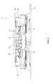
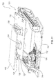
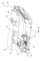
- FIG. 1 shows a lifting table 10 Fig. 3 , On the lifting table 10, two first tools 12 and two transfer devices 14 are arranged. Both the first tools 12 and the transfer devices 14 are preferably arranged movably on the lifting table 10. In the illustration according to the Fig. 1 and 3 The first tools 12 are in a second position and the transfer devices 14 are in a storage position.
- the construction on the lifting table 10 is thus a mirrored structure, so that two sets of the first, second and third components can be processed simultaneously. In this way, for example, a right and a left lamp of a motor vehicle can be produced simultaneously.
- further first tools can be arranged therein together with the associated second tool.
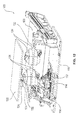
- Fig. 2 shows the upper mounting plate 20 with two second tools 22 and third tools 24 disposed thereon.
- the second tools 22 and the third tools 24 are rigidly disposed on the upper mounting plate 20. This is especially true when a vibrating head is realized for friction welding on the upper mounting plate 20. It is also conceivable for the second 22 and third tools 24 to be movably fastened to the upper fastening plate 20 and for the first tool 12 and the transfer devices 14 to be arranged rigidly on the lifting table 10. Also combinations of these are possible. In this case, however, it must not be a vibration head for friction welding, since high acceleration forces in the vibration head would damage the tool.
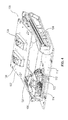
- the plastic welding device 1 is shown in a welding position.
- the lifting table 10 is located near the upper mounting plate 20, so that in the example shown, the first tools 12 are in engagement with the third tools 24 and intermediate components, for example by means of friction welding, can be connected. If the first tools 12 were not in the second position, as shown, but in the first position, then the first tools 12 would be aligned with the second tools 22.
- the operation of the first embodiment of the plastic welding apparatus 1 will be described below with reference to FIGS FIGS. 6 to 16 explained. It should be noted that the first embodiment of the plastic welding device 1 in comparison to the second embodiment of the plastic welding apparatus 100 has no preheating arrangement 130, so that the corresponding method steps are then omitted. At the shown Plastic welding device 1 is exclusively a plastic Reibsch dervorri rect.
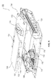
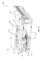
- FIG. 4 shows this in comparison to Fig. 1 changed lifting table 110.
- the lifting table 110 has, like the lifting table 10 also, two first tools 112 and two transfer devices 114, of which only one is shown for reasons of clarity.
- the first tools 112 are in a first position while the transfer devices 114 are in a stored position.
- a preheating arrangement 130 is arranged on the lifting table 110.
- the preheating arrangement 130 consists of a support 132 with four preheating devices 134 arranged thereon, in particular infrared preheating devices.
- the preheating devices 134 disposed on one surface are referred to as the first preheating device, while the preheating devices 134 disposed on the opposite surface of the carrier 132 are referred to as second preheating devices.
- the preheating devices 134 are always arranged in pairs as the first and second preheating device.
- the first and the second preheating device will be referred to as a total preheating device 134.
- the Voricarman extract 130 is located in the Fig. 4 and 5 in a resting position.
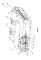
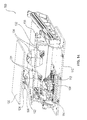
- the complete plastic welding apparatus 100 according to the second embodiment is shown in FIG Fig. 5 shown.
- the upper mounting plate 120 corresponds in structure to the upper mounting plate 20 and was therefore not shown in a separate figure. Analogous to the lifting table 110, in each case only the left half is shown with tools on the upper mounting plate 120 in order to make the overview clearer and also to increase the understanding of the method sequence.
- a device shown friction welding an infrared welding method and a combination thereof is feasible.
- Fig. 6 shows the plastic welding apparatus 100 in an initial position.
- an operator or an automatic loading device has already deposited the first and the second components 102 on the first tools 112 on the lifting table 110.
- the third component 106 has already been deposited on the transfer device 114 in the storage position.
- the lift table 110 is in the initial position and the preheating arrangement is in the rest position.
- the lifting table 110 is moved from the initial position in the direction of the upper mounting plate 120 in a first welding position until the first tool 112 is engaged with the second tool 122. At the same time, welding of the first and second components takes place by means of friction welding. This condition is in Fig. 7 shown.
- the lift table 110 moves down from the first welding position to a first intermediate position. This is in Fig. 8 shown. As soon as the first tool 112 with the composite of first and second component 104 arranged thereon is no longer in engagement with the second tool 122, the first tool 112 can be moved from a first position to a second position. An intermediate state between the first and second positions of the first tool 112 is also in FIG Fig. 8 shown.
- the transfer device 114 is moved with the third component 106 in a transfer position.
- the transfer device 114 is aligned with the third tool 124.
- the first tool with the composite of the first and the second component 104 and the transfer device 114 with the third component 106 and the third tool 124 arranged axially one above the other.
- a method of the lifting table 110 in the transfer position of the lifting table 110 and the transfer of the third component 106 to the third tool 124 This is in Fig. 10 shown.
- the lifting table 110 is moved to a receiving position, as in Fig. 11 shown. In the receiving position, the transfer device 114 is again in the storage position and the first tool 112 is arranged in the second position.
- the first tool 112 is moved to the second position only at a later time, for example, only after the transfer device 114 has been moved back to the storage position after the transfer of the third component 106.
- the preheat assembly After or just before the lift table 110 has reached the pickup position, the preheat assembly is moved away from the rest position and toward a preheat position. An intermediate state between the rest position and the preheat position is in Fig. 12 shown.
- the lifting table 110 is moved into a preheating position of the lifting table 110.
- This preheat position of the lift table 110 is in Fig. 13 shown.
- One of the preheating devices 134 for example the first preheating device, is arranged adjacent to the second component 104 in the first tool 112.
- the preheating device 134 arranged on the opposite surface of the carrier 132 for example the second preheating device, is arranged adjacent to the third component 106 in the third tool 124.
- the lift table 110 moves from the preheat position back to the pickup position. Meanwhile, or after reaching the picking position, the preheating assembly 130 is moved from the preheat position back to the rest position.
- One Intermediate state in the process of Vorierrman extract from the preheat position to the rest position is in Fig. 14 shown.
- the lifting table 110 is moved from the receiving position to a second welding position.
- the second welding position is in Fig. 15 shown.
- the welding in the second welding position takes place by means of friction welding. Due to the previous preheating the linting is reduced compared to pure friction welding, so that the weld looks visually beautiful. Another side effect may be an increase in weld strength. This has already been described above.
- the lift table 110 moves away from the second welding position and, for example, back to its initial position.
- the finished composite of the first, second and third component is arranged in the first tool 112 or preferably in the third tool 124.
- the plastic welding apparatus 100 can be reloaded prior to removal of the finished composite, which further reduces cycle time as compared to conventional plastic welders and thus increases efficiency.
- preheating devices 134 are shown rigidly disposed on carrier 132, in an alternative embodiment preheating devices 134 are movably mounted on carrier 132. In this way, the preheating devices 134 can be aligned with the respective tool. Further alternatively, additional preheating devices 134 may be provided. In addition to the preheating described above, preheating of the first and of the second component 102 before the welding of the first component to the second component analogously to the above-described steps can additionally be realized in both described alternatives. In both described alternatives, the device can then also be operated without friction welding as a pure infrared welding device.
- the preheating devices 134 are also arranged only so that a preheating of the first and the second component 102 before welding can be realized. In this case, it is as in the detailed operation of the plastic welding apparatus 100 set forth a combination of infrared welding and friction welding.
- the described plastic welding process is a plastic friction welding process, a plastic infrared welding process or a combination thereof.
- a first component is arranged on a first tool, a second component on the first component or on a second tool, and a third component on a storage position of the plastic welding device.
- This arrangement can be done manually by an operator or automatically by a robot, a loading device or a loading and unloading device. If the loading is performed by an operator, then in step 1, an intervention protection is provided. This is for example a closing of a housing opening of the plastic welding device or the switching on of a light barrier.
- the plastic welding device comprises a preheating arrangement with at least one preheating device and the second component is arranged in a different tool than the first tool
- step j a method of preheating arrangement from a rest position to a preheating position, so that the at least one preheating with a the tools is aligned.
- step k an at least partial heating of the surface of a component in the tool then takes place in the region to be welded, preferably both components in both tools. After preheating, the preheating arrangement returns to the rest position.
- step b the first tool and the second tool with the first and second components arranged therebetween are then moved relative to one another from an initial position into a first welding position. Before reaching the first welding position, a centering of the first and the second component relative to one another and to the respective tool can take place.
- step c welding of the first and second components takes place in step c.
- the welding takes place by means of friction welding with or without preheating instead. Alternatively, if preheating is present, pure infrared welding can take place.
- step d the first and the second tool are moved with the interposed composite of welded first and second component from the first welding position relative to each other in a first intermediate position.
- step e an automatic transfer of the third component from the storage position by means of a transfer device to one of the tools takes place in step e.
- the plastic welding apparatus has the third tool adjacent the second tool and the first tool is initially in alignment with the second tool in a first position, then in step i, the first tool moves to a second position in alignment with the third tool Tool.
- the step i takes place after step c and before the subsequent step g.
- the plastic welding device comprises the preheating arrangement with the at least one preheating device
- a method of preheating arrangement can be carried out from a rest position to a preheating position, as in step j above, so that the at least one preheating device is aligned with one of the tools.
- step k an at least partial heating of the surface of a component in the tool then takes place in the region to be welded, preferably both components in both tools. After preheating, the preheating arrangement returns to the rest position.
- step f After the transfer of the third component to one of the tools, in step f, the first and the second tool or only the first tool or only the second tool in each case in combination with a third tool relative to each other from the first intermediate position to a second welding position. Before reaching the second welding position, a centering of the first and the second component relative to one another and to the respective tool can take place.
- step g the third component is welded to the composite of welded first and second component via the first and the second tool or via the first or the second tool in combination with the third tool.
- the first and second tools move relative to each other back to the initial position.
- a removal of the finished composite of the first, second and third component takes place manually by the operator or automatically by a robot, a removal device or a loading and unloading device. If the finished composite is removed by an operator, then before removal and after reaching the initial position in step m removal of the intervention protection, so for example, opening the housing opening of the plastic welding device or switching off the light barrier.
Landscapes
- Engineering & Computer Science (AREA)
- Mechanical Engineering (AREA)
- Physics & Mathematics (AREA)
- Electromagnetism (AREA)
- Health & Medical Sciences (AREA)
- Toxicology (AREA)
- Thermal Sciences (AREA)
- Manufacturing & Machinery (AREA)
- Lining Or Joining Of Plastics Or The Like (AREA)
Abstract
Eine Kunststoffschweißvorrichtung (1; 100) zum automatischen Verschweißen von mindestens drei Bauteilen umfasst mindestens ein erstes Werkzeug (12; 112), mindestens ein zweites Werkzeug (22; 122) sowie mindestens eine Übergabevorrichtung (14; 114). Auf dem ersten Werkzeug (12; 112) ist ein erstes Bauteil positionierbar. Das erste (12; 112) und das zweite Werkzeug (22; 122) sind relativ zueinander bewegbar, um das erste Bauteil mit einem zweiten Bauteil (102) zu verschweißen. Die Übergabevorrichtung (14; 114) ist relativ zu mindestens einem der Werkzeuge (12, 22; 112, 122) bewegbar und mit ihr ist automatisch mindestens ein drittes Bauteil (106) einem der Werkzeuge zuführbar. Auf diese Weise ist das mindestens eine dritte Bauteil (106) mit dem Verbund (104) aus erstem und zweitem Bauteil über das erste (12; 112) und das zweite Werkzeug (22; 122) oder über das erste (12; 112) oder das zweite Werkzeug (22; 122) in Kombination mit einem dritten Werkzeug (24; 124) verschweißbar.A plastic welding device (1; 100) for automatic welding of at least three components comprises at least a first tool (12; 112), at least one second tool (22; 122) and at least one transfer device (14; 114). A first component can be positioned on the first tool (12; 112). The first (12; 112) and the second tool (22; 122) are movable relative to one another to weld the first component to a second component (102). The transfer device (14; 114) is movable relative to at least one of the tools (12, 22; 112, 122), and with it at least one third component (106) can be automatically fed to one of the tools. In this way, the at least one third component (106) with the composite (104) of the first and second component via the first (12; 112) and the second tool (22; 122) or via the first (12; 112) or the second tool (22; 122) is weldable in combination with a third tool (24; 124).
Description
Die vorliegende Erfindung betrifft eine Kunststoffschweißvorrichtung zum automatischen Verschweißen von mindestens drei Bauteilen sowie ein Kunststoffschweißverfahren für mindestens drei Bauteile.The present invention relates to a plastic welding apparatus for automatically welding at least three components and a plastic welding method for at least three components.
Kunststoffschweißvorrichtungen umfassen üblicherweise ein Gehäuse mit einem darin angeordneten Unterwerkzeug sowie einem darin angeordneten Oberwerkzeug. Das Unterwerkzeug ist an einem Hubtisch befestigt, wohingegen das Oberwerkzeug starr an einer Oberwerkzeugplatte befestigt ist. Mittels des Hubtischs kann das Unterwerkzeug in Richtung des Oberwerkzeugs verfahren werden, um ein erstes Bauteil im Unterwerkzeug mit einem zweiten Bauteil im Oberwerkzeug zu verschweißen, beispielsweise mittels Reibschweißen.Plastic welding devices usually comprise a housing with a lower tool arranged therein and an upper tool arranged therein. The lower tool is attached to a lifting table, whereas the upper tool is rigidly attached to an upper tool plate. By means of the lifting table, the lower tool can be moved in the direction of the upper tool to weld a first component in the lower tool with a second component in the upper tool, for example by friction welding.
Derartige Kunststoffschweißvorrichtungen werden zum Beispiel in der Automobilindustrie oder in der Medizintechnik eingesetzt. In der Automobilindustrie werden solche Kunststoffschweißvorrichtungen zur Herstellung von Leuchten genutzt, können aber auch bei der Herstellung anderer Bauteile oder Bauteilgruppen verwendet werden, die aus Kunststoffen bestehen oder Kunststoffe enthalten. In ähnlicher Weise kann die Kunststoffschweißvorrichtung bei der Herstellung von Geräten und/oder Bauteilgruppen in der Medizintechnik oder bei der Herstellung von Gebrauchsgütern Verwendung finden.Such plastic welding devices are used for example in the automotive industry or in medical technology. In the automotive industry, such plastic welding devices are used for the production of lights, but can also be used in the manufacture of other components or groups of components that consist of plastics or plastics. Similarly, the plastic welding apparatus can be used in the manufacture of devices and / or component groups in medical technology or in the manufacture of consumer goods.
Der Arbeitsablauf mit der bekannten Kunststoffschweißvorrichtung ist wie folgt. Ein Bediener legt zunächst ein erstes Bauteil in die Aufnahme des Unterwerkzeugs ein. Anschließend positioniert er ein zweites Bauteil auf dem ersten Bauteil im Unterwerkzeug. Danach startet der Bediener den Schweißprozess, wobei sich zunächst eine Gehäuseöffnung schließt, damit ein Eingreifen in die Kunststoffschweißvorrichtung zum Schutz des Bedieners nicht mehr möglich ist. Nach dem Schließen des Gehäuses fährt der Hubtisch mit dem Unterwerkzeug und den darauf angeordneten Bauteilen aus einer Anfangsposition in Richtung des Oberwerkzeugs, bis das zweite Bauteil im Oberwerkzeug anliegt und sich der Hubtisch und die beiden Bauteile in einer Schweißposition befinden. Nun erfolgt ein Verschweißen des ersten Bauteils mit dem zweiten Bauteil mittels Reibschweißen. Nach Beendigung des Reibschweißens fährt der Hubtisch mit dem Unterwerkzeug und dem darin angeordnetem Verbund aus erstem und zweitem Bauteil von der Schweißposition zurück in die Anfangsposition. Nun wird die Gehäuseöffnung wieder geöffnet und der Bediener kann den Verbund aus erstem und zweitem Bauteil entnehmen.The procedure with the known plastic welding device is as follows. An operator first inserts a first component into the receptacle of the lower tool. He then positions a second component on the first component in the lower tool. Thereafter, the operator starts the welding process, wherein initially closes a housing opening, so that an intervention in the plastic welding device to protect the operator is no longer possible. After closing the housing, the lifting table moves with the lower tool and the components arranged thereon from an initial position in the direction of the upper tool until the second component rests in the upper tool and the lifting table and the two components are in a welding position. Now, a welding of the first component with the second component by means of friction welding. After completion of the Reibschweißens moves the lift table with the lower tool and arranged therein composite of first and second component from the welding position back to the initial position. Now the housing opening is opened again and the operator can remove the composite of first and second component.
Sollte der Bediener ein weiteres, drittes Bauteil mit dem Verbund aus erstem und zweitem Bauteil verschweißen wollen, dann legt er das dritte Bauteil auf den Verbund aus erstem und zweitem Bauteil im Unterwerkzeug und startet den Ablauf von vorne.If the operator wants to weld another, third component with the composite of the first and second component, then he places the third component on the composite of the first and second component in the lower tool and starts the process from the front.
Diese bekannte Kunststoffschweißvorrichtung sowie das entsprechend beschriebene Schweißverfahren sind nachteilig, da das Öffnen der Gehäuseöffnung, das Beladen mit dem dritten Bauteil und das erneute Starten des Verfahrens zeitaufwendig sind.This known plastic welding device and the welding method described accordingly are disadvantageous because the opening of the housing opening, the loading of the third component and the restarting of the process are time consuming.
Die Aufgabe der vorliegenden Erfindung ist daher, eine Kunststoffschweißvorrichtung bereitzustellen, die ein automatisches Verschweißen von mindestens drei Teilen ermöglicht. Weiterhin soll ein entsprechendes Kunststoffschweißverfahren bereitgestellt werden.The object of the present invention is therefore to provide a plastic welding device which enables automatic welding of at least three parts. Furthermore, a corresponding plastic welding process is to be provided.
Die obige Aufgabe wird gelöst durch eine Kunststoffschweißvorrichtung zum automatischen Verschweißen von mindestens drei Bauteilen gemäß dem unabhängigen Patentanspruch 1 sowie ein automatisches Kunststoffschweißverfahren für mindestens drei Bauteile gemäß dem unabhängigen Patentanspruch 15. Weitere vorteilhafte Ausgestaltungen ergeben sich aus der nachfolgenden Beschreibung, den Zeichnungen sowie den abhängigen Patentansprüchen.The above object is achieved by a plastic welding device for automatic welding of at least three components according to independent claim 1 and an automatic plastic welding method for at least three components according to independent claim 15. Further advantageous embodiments will become apparent from the following description, the drawings and the dependent claims ,
Die erfindungsgemäße Kunststoffschweißvorrichtung zum automatischen Verschweißen von mindestens drei Bauteilen umfasst mindestens ein erstes Werkzeug, auf dem ein erstes Bauteil positionierbar ist, mindestens ein zweites Werkzeug, wobei das erste und das zweite Werkzeug relativ zueinander bewegbar sind, um das erste Bauteil mit einem zweiten Bauteil zu verschweißen, sowie mindestens eine Übergabevorrichtung, die relativ zu mindestens einem der Werkzeuge bewegbar ist und mit der automatisch mindestens ein zweites und/oder ein drittes Bauteil einem der Werkzeuge zuführbar ist, sodass das mindestens eine dritte Bauteil mit dem Verbund aus erstem und zweitem Bauteil über das erste und das zweite Werkzeug oder über das erste oder das zweite Werkzeug in Kombination mit einem dritten Werkzeug verschweißbar ist.The inventive plastic welding device for automatically welding at least three components comprises at least one first tool on which a first component can be positioned, at least one second tool, wherein the first and the second tool are movable relative to each other to the first component with a second component welding, and at least one transfer device which is movable relative to at least one of the tools and with which automatically at least a second and / or a third component can be fed to one of the tools, so that the at least one third component with the composite of first and second component over the first and the second tool or via the first or the second tool in combination with a third tool is weldable.
Vorzugsweise handelt es sich bei der Kunststoffschweißvorrichtung um eine Kunststoff-Reibschweißvorrichtung, eine Kunststoff-Infrarot-Schweißvorrichtung oder eine Kombination davon. Beispielhaft wird die Kunststoffschweißvorrichtung zunächst als Kunststoff-Reibschweißvorrichtung beschrieben.Preferably, the plastic welding device is a plastic friction welding device, a plastic infrared welding device or a combination thereof. By way of example, the plastic welding device will initially be described as a plastic friction welding device.
Hierbei ist das erste Werkzeug vorzugsweise an einem ersten Träger angeordnet, insbesondere an einem Hubtisch. Das zweite Werkzeug ist vorzugsweise an einem zweiten Träger angeordnet, insbesondere an einer oberen Befestigungsplatte. Vorzugsweise sind der erste und zweite Träger relativ zueinander bewegbar. Auf dieser konstruktiven Grundlage sind auch das erste und zweite Werkzeug derart relativ zueinander bewegbar, dass mindestens zwei Bauteile miteinander verbindbar sind. So ist es beispielsweise bevorzugt, dass der erste Träger starr angeordnet ist, während die Werkzeuge und Bauteile relativ zueinander über die Bewegung des Hubtisches bewegt werden. Dieser Aufbau wurde im einleitenden Teil bereits kurz erläutert.In this case, the first tool is preferably arranged on a first carrier, in particular on a lifting table. The second tool is preferably arranged on a second carrier, in particular on an upper mounting plate. Preferably, the first and second carrier are movable relative to each other. On this structural basis, the first and second tools are movable relative to each other in such a way that at least two components can be connected to one another. Thus, for example, it is preferred that the first carrier is rigidly arranged while the tools and components are moved relative to one another via the movement of the lifting table. This structure has already been briefly explained in the introductory part.
Darüber hinaus, und anders als bei einer bekannten Kunststoffschweißvorrichtung, umfasst die erfindungsgemäße Kunststoffschweißvorrichtung die mindestens eine Übergabevorrichtung, mit der das dritte Bauteil einem der Werkzeuge automatisch zuführbar ist, wie nachstehend erläutert. Das dritte Bauteil wird hierzu erfindungsgemäß bereits zu Beginn in der Kunststoffschweißvorrichtung gelagert bzw. angeordnet. Zur besseren Verständlichkeit wird nun die erfindungsgemäße Kunststoffschweißvorrichtung im Betrieb als Kunststoff-Reibschweißvorrichtung beschrieben.In addition, and unlike a known plastic welding device, the plastic welding device according to the invention comprises the at least one transfer device, with which the third component is automatically fed to one of the tools, as explained below. For this purpose, according to the invention, the third component is already stored or arranged at the beginning in the plastic welding device. For better understanding, the plastic welding device according to the invention will now be described in operation as a plastic friction welding device.
Wie bei einer herkömmlichen Kunststoffschweißvorrichtung ordnet ein Bediener das erste Bauteil im ersten Werkzeug an. Das zweite Bauteil wird vom Bediener auf dem ersten Bauteil angeordnet. Alternativ kann der Bediener das zweite Bauteil auch direkt im zweiten Werkzeug anordnen. Das dritte Bauteil wird in einer Lagerposition in der Kunststoffschweißvorrichtung vom Bediener angeordnet. Nachdem alle Bauteile an ihrer Position in der Kunststoffschweißvorrichtung angeordnet worden sind, startet der Bediener die Kunststoffschweißvorrichtung. Alternativ zum Bediener sind alle oder einzelne dieser anfänglichen Beladeschritte von einem Roboter, einer Beladeeinheit oder einer Belade- und Entnahmeeinheit durchführbar. Diese und die nachfolgenden Schritte des Schweißverfahrens werden vorzugsweise durch eine Steuervorrichtung der Kunststoffschweißvorrichtung vorgegeben.As with a conventional plastic welding apparatus, an operator places the first component in the first tool. The second component is arranged by the operator on the first component. Alternatively, the operator can also arrange the second component directly in the second tool. The third component is arranged in a storage position in the plastic welding device by the operator. After all the components have been placed in position in the plastic welding device, the operator starts the plastic welding device. As an alternative to the operator, all or some of these initial loading steps can be performed by a robot, a loading unit or a loading and unloading unit. These and the subsequent steps of the welding process are preferably predetermined by a control device of the plastic welding device.
Nun fährt in einem ersten Schritt der Hubtisch mit dem ersten Werkzeug von einer Anfangsposition in Richtung des zweiten Werkzeugs bis in eine erste Schweißposition. Optional erfolgt vor dem vollständigen Verfahren in die erste Schweißposition ein automatisches Zentrieren des ersten und des zweiten Bauteils zueinander sowie zum jeweiligen Werkzeug. In der Schweißposition erfolgt ein Verschweißen des ersten und des zweiten Bauteils miteinander mittels Reibschweißen.Now moves in a first step of the lifting table with the first tool from an initial position in the direction of the second tool to a first welding position. Optionally, prior to the complete procedure in the first welding position, an automatic centering of the first and the second component relative to one another and to the respective tool takes place. In the welding position, the first and the second component are welded together by means of friction welding.
Wenn der Reibschweißvorgang abgeschlossen ist, dann fährt der Hubtisch aus der Schweißposition heraus in eine erste Zwischenposition, wodurch sich das erste und das zweite Werkzeug voneinander weg bewegen. Bei der Zwischenposition kann es sich um die Anfangsposition oder eine beliebige Position zwischen erster Schweißposition und Anfangsposition handeln. Für das nachfolgende Beispiel verbleibt der Verbund aus verschweißtem erstem und zweitem Bauteil im ersten Werkzeug. Alternativ ist der Verbund auch im zweiten Werkzeug weiter festhaltbar, beispielsweise mechanisch oder mittels Unterdruck.When the friction welding operation is completed, the lift table moves from the welding position to a first intermediate position, whereby the first and second tools move away from each other. The intermediate position may be the starting position or any position between the first welding position and the starting position. For the following example, the composite of welded first and second component remains in the first tool. Alternatively, the composite can also be retained in the second tool, for example mechanically or by means of negative pressure.
Nun wird das dritte Bauteil aus der Lagerposition von der Übergabevorrichtung automatisch einem der Werkzeuge zugeführt. Bei der Übergabevorrichtung handelt es sich um jede Vorrichtung, mit der automatisch das dritte Bauteil von einer Lagerposition einem der Werkzeuge zuführbar ist. Beispielsweise handelt es sich um verfahrbare Hebel- und Schwenkmechanismen, verfahrbare Werkzeuge, einen Roboterarm oder vorzugsweise um die nachfolgend in der detaillierten Beschreibung erläuterte Vorrichtung. In einer weiteren Ausführungsform ist die Übergabevorrichtung ebenfalls als weiteres Werkzeug ausgebildet.Now, the third component from the storage position of the transfer device is automatically fed to one of the tools. The transfer device is any device with which automatically the third component can be fed from one storage position to one of the tools. By way of example, these are movable lever and pivot mechanisms, movable tools, a robot arm or, preferably, the apparatus explained below in the detailed description. In a further embodiment, the transfer device is also designed as a further tool.
Die Zufuhr des dritten Bauteils zum ersten oder zweiten Werkzeug setzt voraus, dass das dritte Bauteil eine Form bzw. Außenkontur aufweist, die der Form des ersten oder des zweiten Bauteils gleicht. Im vorliegenden Beispiel wird das dritte Bauteil dem zweiten Werkzeug zugeführt, weist also eine Form auf, die passend oder identisch zur Form des zweiten Bauteils gestaltet ist. Alternativ ist das dritte Bauteil jedoch auch auf dem Verbund aus erstem und zweitem Bauteil im ersten Werkzeug ablegbar. Sollte das dritte Bauteil eine Form aufweisen, die identisch mit dem ersten Bauteil ist, dann verbleibt der Verbund aus erstem und zweitem Bauteil nach dem Verschweißen im zweiten Werkzeug, so dass das dritte Bauteil im ersten Werkzeug automatisch durch die Übergabevorrichtung positionierbar ist.The supply of the third component to the first or second tool requires that the third component has a shape or outer contour that is similar to the shape of the first or the second component. In the present example, the third component becomes the second tool supplied, so has a shape that is designed to match or identical to the shape of the second component. Alternatively, however, the third component can also be deposited on the composite of first and second component in the first tool. If the third component has a shape that is identical to the first component, then the composite of the first and second component remains after welding in the second tool, so that the third component in the first tool can be automatically positioned by the transfer device.
Nachdem das dritte Bauteil in einem der Werkzeuge angeordnet worden ist, fährt der Hubtisch von der ersten Zwischenposition in eine zweite Schweißposition, also in Richtung des zweiten Werkzeugs. Auch hier kann vor Erreichen der zweiten Schweißposition wieder ein optionaler Zentrier- und/oder Positionierschritt durchgeführt werden, wie er oben für das ersten und das zweite Bauteil beschrieben wurde. Mittels dieses zweiten Zentrierschrittes wird das dritte Bauteil mit dem Verbund aus erstem und zweitem Bauteil ausgerichtet. Ebenso werden das dritte Bauteil mit dem zweiten Werkzeug und der Verbund aus erstem und zweitem Bauteil mit dem ersten Werkzeug ausgerichtet. Dann erfolgt das Verschweißen des dritten Bauteils mit dem Verbund aus erstem und zweitem Bauteil mittels Reibschweißen.After the third component has been arranged in one of the tools, the lifting table travels from the first intermediate position to a second welding position, that is to say in the direction of the second tool. Again, before reaching the second welding position again an optional centering and / or positioning step can be performed, as described above for the first and the second component. By means of this second centering step, the third component is aligned with the composite of the first and second component. Likewise, the third component with the second tool and the composite of the first and second components are aligned with the first tool. Then, the welding of the third component with the composite of the first and second component takes place by means of friction welding.
Nach Beendigung des Reibschweißvorgangs fährt der Hubtisch aus der zweiten Schweißposition heraus und bevorzugt zurück in die Anfangsposition. Der Verbund aus erstem, zweitem und drittem Bauteil ist hierbei wahlweise im ersten oder im zweiten Werkzeug angeordnet und wird entsprechend vom Bediener entnommen. Alternativ ist der Verbund von einem Roboter, einer Entnahmeeinheit oder einer Belade- und Entnahmeeinheit automatisch entnehmbar.After completion of the friction welding process, the lift table moves out of the second welding position and preferably back to the initial position. The composite of first, second and third component is hereby optionally arranged in the first or in the second tool and is removed accordingly by the operator. Alternatively, the composite of a robot, a removal unit or a loading and unloading unit can be removed automatically.
Ein Vorteil der erfindungsgemäßen Kunststoffschweißvorrichtung ist, dass die Taktzeit im Vergleich zu einer herkömmlichen Kunststoffschweißvorrichtung reduziert ist, da die Zeit zum Beladen der Kunststoffschweißvorrichtung mit dem dritten Bauteil nicht benötigt wird. Dies führt zu einer höheren Effizienz und somit zu einer Kostenreduktion im Vergleich zu herkömmlichen Kunststoffschweißvorrichtungen.An advantage of the plastic welding device according to the invention is that the cycle time is reduced in comparison to a conventional plastic welding device, since the time for loading the plastic welding device with the third component is not required. This leads to a higher efficiency and thus to a cost reduction compared to conventional plastic welding devices.
Die Taktzeit ist weiter reduzierbar, wenn der fertige Verbund aus erstem, zweitem und drittem Bauteil im zweiten Werkzeug angeordnet ist, da dann direkt ein Beladen mit dem ersten, dem zweiten und dem dritten Bauteil erfolgen kann, ohne dass zuerst der fertige Verbund entnommen werden muss.The cycle time can be further reduced if the finished composite of the first, second and third component is arranged in the second tool, since then directly loading with the first, the second and the third component can be done without first the finished composite must be removed ,
Häufig tritt in der Praxis der Fall auf, dass das dritte Bauteil eine Form bzw. Außenkontur aufweist, die von der des ersten und der des zweiten Bauteils verschieden ist. In diesem Fall weist die Kunststoffschweißvorrichtung vorzugsweise ein drittes Werkzeug für das dritte Bauteil auf. Das dritte Werkzeug ist in Abhängigkeit vom Verfahrensablauf benachbart zum ersten oder zweiten Werkzeug angeordnet. Vorzugsweise, und wie nachfolgend beschrieben, ist das dritte Werkzeug am zweiten Träger benachbart dem zweiten Werkzeug angeordnet, also vorzugsweise an der oberen Befestigungsplatte.Often, in practice, the case arises that the third component has a shape or outer contour that is different from that of the first and the second component. In this case, the plastic welding device preferably has a third tool for the third component. The third tool is arranged adjacent to the first or second tool depending on the process. Preferably, and as described below, the third tool is disposed on the second carrier adjacent to the second tool, that is preferably on the upper mounting plate.
Der Ablauf des Verfahrens ist bis zum Übergeben des dritten Bauteils identisch mit den oben beschriebenen Verfahrensschritten. Anstelle des automatischen Übergebens des dritten Bauteils an das erste oder das zweite Werkzeug erfolgt das automatische Übergeben des dritten Bauteils nun allerdings an das dritte Werkzeug. Weiterhin muss, da das erste Werkzeug in einer ersten Position mit dem zweiten Werkzeug zum Herstellen des Verbunds aus erstem und zweitem Bauteil ausgerichtet ist, das erste Werkzeug nun in eine zweite Position verfahren werden, in der es mit dem dritten Werkzeug ausgerichtet ist. Vorzugsweise ist das erste Werkzeug daher auf dem Hubtisch bewegbar zwischen einer ersten Position, in der es mit dem zweiten Werkzeug ausgerichtet ist, und einer zweiten Position, in der es mit dem dritten Werkzeug ausgerichtet ist. Sollte das dritte Werkzeug woanders angeordnet sein, dann muss sich die beispielhaft beschriebene Anordnung entsprechend ändern. In jedem Fall muss das Werkzeug, das den Verbund aus erstem und zweitem Bauteil trägt oder hält, mit dem Werkzeug ausrichtbar sein, das während des Verfahrensablaufs das dritte Bauteil aufweist oder hält.The sequence of the method is identical to the method steps described above until the third component has been handed over. Instead of automatically transferring the third component to the first or the second tool, however, the third component is automatically transferred to the third tool. Furthermore, since the first tool is aligned in a first position with the second tool for establishing the first and second component assembly, the first tool must now be moved to a second position where it is aligned with the third tool. Preferably, the first tool is therefore movable on the lifting table between a first position, in which it is aligned with the second tool, and a second position, in which it is aligned with the third tool. Should the third tool be located elsewhere, then the arrangement described by way of example must change accordingly. In any case, the tool that carries or holds the composite of the first and second component must be alignable with the tool that has or holds the third component during the course of the process.
Nachdem die Ausrichtung der zum Verschweißen des dritten Bauteils mit dem Verbund erforderlichen Werkzeuge hergestellt wurde, läuft das weitere Verfahren analog zum oben beschriebenen Verfahren ab. Es erfolgt also ein Verfahren des Hubtischs aus der ersten Zwischenposition in Richtung des dritten Werkzeugs in eine zweite Schweißposition. Auch hier ist vor Erreichen der endgültigen Schweißposition ein optionaler Zentrier- oder Positionierschritt durchführbar. Dann erfolgt das Verschweißen des dritten Bauteils mit dem Verbund aus erstem und zweitem Bauteil mittels Reibschweißen. Danach fährt der Hubtisch aus der zweiten Schweißposition heraus und beispielsweise zurück in die Anfangsposition. Der Verbund aus erstem, zweitem und drittem Bauteil ist hierbei wahlweise im ersten oder im dritten Werkzeug angeordnet und wird entsprechend vom Bediener entnommen. Alternativ ist der Verbund von einem Roboter, einer Entnahmeeinheit oder einer Belade- und Entnahmeeinheit automatisch entnehmbar.After the alignment of the tools required for welding the third component with the composite has been established, the further method proceeds analogously to the method described above. Thus, there is a method of lifting table from the first intermediate position in the direction of the third tool in a second welding position. Also Here, an optional centering or positioning step is feasible before reaching the final welding position. Then, the welding of the third component with the composite of the first and second component takes place by means of friction welding. Thereafter, the lift table moves out of the second welding position and, for example, back to the starting position. The composite of first, second and third component is hereby optionally arranged in the first or in the third tool and is removed accordingly by the operator. Alternatively, the composite of a robot, a removal unit or a loading and unloading unit can be removed automatically.
Ein Vorteil dieser Ausführungsform ist, dass mindestens drei Bauteile unterschiedlicher Form automatisch miteinander verschweißbar sind. Im Vergleich zu einer herkömmlichen Kunststoffschweißvorrichtung stellt dies den oben bereits diskutierten Taktzeitvorteil bereit.An advantage of this embodiment is that at least three components of different shape are automatically welded together. Compared to a conventional plastic welding apparatus, this provides the cycle time advantage already discussed above.
In einer weiteren bevorzugten Ausführungsform ist die Übergabevorrichtung am ersten Träger angeordnet, also insbesondere am Hubtisch, und zwischen einer Lagerposition und einer Übergabeposition bewegbar. Dies stellt zum einen den Vorteil bereit, dass die Übergabevorrichtung mittels des Hubtischs zum zweiten und/oder dritten Werkzeug bewegbar ist. Ein weiterer Vorteil ist, dass die Übergabevorrichtung selbst die Lagerposition für das dritte Bauteil zu Beginn bereitstellt. Somit ist eine weitere Vereinfachung des Verfahrens gegeben, da das dritte Bauteil nicht erst von der Übergabevorrichtung von einer gesonderten Lagerposition innerhalb der Kunststoffschweißvorrichtung aufgenommen werden muss.In a further preferred embodiment, the transfer device is arranged on the first carrier, ie in particular on the lifting table, and movable between a storage position and a transfer position. This provides, on the one hand, the advantage that the transfer device can be moved by means of the lifting table to the second and / or third tool. Another advantage is that the transfer device itself provides the storage position for the third component at the beginning. Thus, a further simplification of the method is given because the third component does not have to be taken up by the transfer device from a separate storage position within the plastic welding device.
In einer weiterhin bevorzugten Ausführungsform weist die Kunststoffschweißvorrichtung eine Vorwärmanordnung mit einer ersten Vorwärmvorrichtung auf. Die erste Vorwärmvorrichtung ist vorzugsweise eine Intrarot-Vorwärmvorrichtung. Die Vorwärmanordnung selbst ist zwischen einer Ruheposition und einer Vorwärmposition bewegbar. In der Vorwärmposition ist die Vorwärmvorrichtung mit einem der Werkzeuge ausgerichtet, so dass ein Bauteil in dem entsprechenden Werkzeug zumindest teilweise im zu verschweißenden Bereich erwärmbar ist. Das Vorwärmen des entsprechenden Bauteils findet vor einem Verschweißen mit dem weiteren Bauteil oder dem Verbund statt. Beispielsweise erfolgt das Vorwärmen vor dem Verschweißen des ersten Bauteils mit dem zweiten Bauteil. Alternativ oder zusätzlich erfolgt das Vorwärmen ebenso vor dem Verschweißen des dritten Bauteils mit dem Verbund aus erstem und zweitem Bauteil.In a further preferred embodiment, the plastic welding device has a preheating arrangement with a first preheating device. The first preheating device is preferably an intra-preheating device. The preheating arrangement itself is movable between a rest position and a preheat position. In the preheating position, the preheating device is aligned with one of the tools, so that a component in the corresponding tool can be heated at least partially in the area to be welded. The preheating of the corresponding component takes place before welding to the other component or the composite. For example, the preheating takes place before the welding of the first component to the second component. alternative or in addition, the preheating also takes place before the welding of the third component with the composite of the first and second component.
Bezugnehmend auf den oben beschriebenen Verfahrensablauf enthält dieser nun weitere Verfahrensschritte nachdem der Hubtisch die erste und/oder die zweiten Zwischenposition erreicht hat. Nämlich das Verfahren der Vorwärmanordnung von einer Ruheposition in eine Vorwärmposition, so dass die mindestens eine Vorwärmvorrichtung mit einem der Werkzeuge ausgerichtet ist. Danach wird die Vorwärmvorrichtung in Anlage mit dem zu erwärmenden Werkzeug gebracht und es erfolgt ein zumindest teilweises Erwärmen der Oberfläche des Bauteils im Werkzeug im zu verschweißenden Bereich. Anschließend wird die erste Vorwärmvorrichtung wieder aus dem Eingriff mit dem Bauteil gebracht und die Vorwärmanordnung wird von der Vorwärmposition in die Ruheposition zurück gefahren.With reference to the method sequence described above, the latter now contains further method steps after the lifting table has reached the first and / or the second intermediate position. Namely, the method of preheating arrangement from a rest position to a preheat position, such that the at least one preheater is aligned with one of the tools. Thereafter, the preheating is brought into contact with the tool to be heated and there is an at least partial heating of the surface of the component in the tool in the area to be welded. Subsequently, the first preheating is brought back out of engagement with the component and the preheating is driven back from the preheating position in the rest position.
Ein Vorteil des Vorwärmens ist, dass eine optisch anspruchsvollere Schweißnaht erzielbar ist, die insbesondere im Bereich der Automobilindustrie beispielsweise bei Leuchten-Anwendungen gewünscht ist. Die optisch anspruchsvollere Schweißnaht bzw. kosmetische Schweißnaht ist insbesondere die Folge einer verminderten oder ganz unterbundenen Fusselbildung während eines Reibschweißens der vorgewärmten Bauteile. Ein zusätzlicher Vorteil der Vorwärmung ist insbesondere die erhöhte Festigkeit der späteren Schweißverbindung bei ausgewählten Kunststoffen.An advantage of preheating is that a more visually sophisticated weld is achievable, which is particularly desirable in the automotive industry, for example in lighting applications. The optically more demanding weld seam or cosmetic weld seam is in particular the result of a reduced or completely inhibited formation of lint during friction welding of the preheated components. An additional advantage of the preheating is in particular the increased strength of the subsequent welded joint in selected plastics.
Alternativ zur oben beschriebenen Kombination aus Vorwärmen und Reibschweißen ist auch ein Verschweißen der Bauteile alleine aufgrund der Vorwärmanordnung realisierbar. In dieser bevorzugten Ausführungsform umfasst die Vorwärmanordnung eine zweite Vorwärmvorrichtung, die insbesondere passend oder komplementär zur ersten Vorwärmvorrichtung ausgebildet ist und die auf einer der ersten Vorwärmvorrichtung gegenüber liegenden Oberfläche eines Trägers der Vorwärmanordnung angeordnet ist.As an alternative to the combination of preheating and friction welding described above, it is also possible to weld the components on the basis of the preheating arrangement alone. In this preferred embodiment, the preheating arrangement comprises a second preheating device, which is particularly suitable or complementary to the first preheating device and which is arranged on a surface of a carrier of the preheating arrangement opposite the first preheating device.
Die Vorwärmanordnung ist in einer Ausführungsform frei im Raum bewegbar. Dies gilt ebenso für die weiteren Komponenten, wie Werkzeuge und Übergabevorrichtung. Diese unabhängige Bewegung im Raum wird nachfolgend am Beispiel der Vorwärmanordnung kurz erläutert. Hierbei ist die Vorwärmanordnung entlang zweier separater Achsen bewegbar. Auf diese Weise ist die Vorwärmanordnung beispielsweise neben dem Hubtisch entlang der ersten Achse in vertikaler Richtung verfahrbar und entlang der zweiten Achse in horizontaler Richtung zwischen Hubtisch und oberer Befestigungsplatte verfahrbar. Alternativ ist die Vorwärmanordnung konstruktiv mit dem Hubtisch verbunden, so dass eine vertikale Bewegung zusammen mit dem Hubtisch realisierbar ist. Diese Beispiele gelten analog für die jeweiligen Werkzeuge sowie die Übergabevorrichtung.The preheating arrangement is freely movable in space in one embodiment. This also applies to the other components, such as tools and transfer device. This independent movement in space is briefly explained below using the example of the preheating arrangement. Here, the preheating arrangement is movable along two separate axes. In this way, the preheating arrangement can be moved, for example, next to the lifting table along the first axis in the vertical direction and along the second axis in the horizontal direction between the lifting table and upper mounting plate movable. Alternatively, the preheating arrangement is structurally connected to the lifting table, so that a vertical movement can be realized together with the lifting table. These examples apply analogously to the respective tools as well as the transfer device.
Bezugnehmend auf das einführende Beispiel wird die Funktionsweise einer solchen reinen Kunststoff-Infrarot-Schweißvorrichtung kurz erläutert. Hierbei wird davon ausgegangen, dass das zweite Bauteil bereits im zweiten Werkzeug angeordnet ist und sich der Hubtisch entweder in der Anfangsposition oder in einer zweiten Zwischenposition befindet. Sowohl die Anfangsposition als auch die zweite Zwischenposition stellt einen Abstand zwischen erstem und zweitem Werkzeug bereit, der ausreicht, damit die Vorwärmanordnung aus der Ruheposition in die Vorwärmposition zwischen die beiden Werkzeuge verfahrbar ist. Sobald die Vorwärmanordnung die Vorwärmposition erreicht hat, wird die Vorwärmanordnung zusammen mit dem Hubtisch in Richtung des zweiten Werkzeugs verfahren, bis die erste Vorwärmvorrichtung beispielsweise benachbart dem ersten Bauteil im ersten Werkzeug und die zweite Vorwärmvorrichtung beispielsweise benachbart dem zweiten Bauteil im zweiten Werkzeug angeordnet ist. Diese Position des Hubtischs wird auch als Vorwärmposition des Hubtischs bezeichnet.Referring to the introductory example, the operation of such a pure plastic infrared welding apparatus will be briefly explained. In this case, it is assumed that the second component is already arranged in the second tool and the lifting table is either in the initial position or in a second intermediate position. Both the initial position and the second intermediate position provide a distance between the first and second tools sufficient to allow the preheating assembly to be moved from the rest position to the preheat position between the two tools. As soon as the preheating arrangement has reached the preheating position, the preheating arrangement is moved together with the lifting table in the direction of the second tool until the first preheating device, for example adjacent to the first component in the first tool and the second preheating device, for example adjacent to the second component in the second tool. This position of the lifting table is also referred to as the preheating position of the lifting table.
Nun werden die Oberflächen der beiden Bauteile vorgewärmt. Nach dem Vorwärmen fährt der Hubtisch zurück in die zweite Zwischenposition. Sobald der Hubtisch die zweite Zwischenposition erreicht hat wird die Vorwärmanordnung zurück in die Ruheposition verfahren. Anschließend fährt der Hubtisch in die erste Schweißposition, um das erste Bauteil mit dem zweiten Bauteil durch Druck und ohne Reibschweißen in den vorerwärmten Bereichen miteinander zu verbinden. Zum Verschweißen des dritten Bauteils mit dem Verbund aus erstem und zweitem Bauteil laufen die oben beschriebenen Schritte analog ab. Sollte ein drittes Werkzeug vorhanden sein, dann sind die entsprechenden Vorwärmvorrichtungen entweder bewegbar am Träger angeordnet oder es ist eine entsprechende Anzahl an Vorwärmvorrichtungen vorhanden.Now the surfaces of the two components are preheated. After preheating the lift table moves back to the second intermediate position. As soon as the lifting table has reached the second intermediate position, the preheating arrangement is moved back into the rest position. Subsequently, the lift table moves to the first welding position to connect the first component to the second component by pressure and without friction welding in the preheated areas. For welding the third component to the composite of the first and second components, the steps described above proceed analogously. Should a third tool be present, then the corresponding preheating devices are either movably mounted on the carrier or there is a corresponding number of preheating devices.
Ein Vorteil des reinen Infrarotschweißens ist die partikelfreie Schweißverbindung, die insbesondere im Bereich der Medizintechnik erforderlich ist.An advantage of pure infrared welding is the particle-free welded connection, which is required in particular in the field of medical technology.
In einer weiteren Ausführungsform sind das Reibschweißen und das Infrarotschweißen kombiniert. Hierzu findet das Verschweißen nicht ausschließlich unter Druck, sondern unter Anwendung des Eingangs beschriebenen Reibschweißens statt. Theoretisch ist eine Vielzahl von Kombinationsmöglichkeiten aufgrund des oben beschriebenen Verfahrens möglich, von denen die wichtigsten nachfolgend kurz aufgeführt sind: a) reines Reibschweißen aller drei Bauteile, b) reines Infrarotschweißen aller drei Bauteile, c) Reibschweißen des ersten und des zweiten Bauteils mit und ohne Vorwärmen, d) Reibschweißen des dritten Bauteils und des Verbunds mit und ohne Vorwärmen, e) reines Infrarotschweißen des ersten und des zweiten Bauteils, f) reines Infrarotschweißen des dritten Bauteils und des Verbunds.In another embodiment, the friction welding and the infrared welding are combined. For this purpose, the welding takes place not only under pressure, but using the friction welding described at the beginning instead. Theoretically, a variety of possible combinations due to the method described above are possible, of which the most important are listed briefly below: a) pure friction welding of all three components, b) pure infrared welding of all three components, c) friction welding of the first and the second component with and without Preheating, d) friction welding of the third component and the assembly with and without preheating, e) pure infrared welding of the first and the second component, f) pure infrared welding of the third component and the composite.
In einer ebenfalls bevorzugten Ausführungsform umfasst die Kunststoffschweißvorrichtung mindestens zwei erste und zweite Werkzeuge. Dies ist insbesondere bei der Herstellung von Leuchten im Automobilbereich relevant, da auf diese Weise immer eine rechte und eine linke Leuchte eines Fahrzeugs gleichzeitig herstellbar sind. Abhängig von dem zur Verfügung stehenden Platz kann die Vorrichtung auch weitere erste und zweite Werkzeuge aufweisen. Das gleiche gilt für gegebenenfalls weitere erforderliche Werkzeuge aufgrund des dritten Bauteils oder weiterer Bauteile sowie die entsprechenden Vorwärmvorrichtungen der Vorwärmanordnung.In a likewise preferred embodiment, the plastic welding device comprises at least two first and second tools. This is particularly relevant in the manufacture of lights in the automotive sector, as always a right and a left lamp of a vehicle can be produced in this way. Depending on the available space, the device may also have further first and second tools. The same applies to optionally further required tools due to the third component or other components and the corresponding preheating the Vorwärmanordnung.
Vorteilhafterweise verfügt die Kunststoffschweißvorrichtung über ein Gehäuse mit einem Eingriffschutz. Bei dem Eingriffschutz kann es sich um einen mechanischen Eingriffschutz, wie beispielsweise eine mittels einer Türe schließbare Gehäuseöffnung handeln. Alternativ ist eine Lichtschranke vorgesehen, die das Schweißverfahren bei Unterbrechung anhält. Innerhalb des Gehäuses sind das erste und das zweite Werkzeug sowie die Lagerposition des dritten Bauteils und die Übergabevorrichtung angeordnet. Falls erforderlich oder vorhanden ist ebenfalls das dritte Werkzeug und/oder die Vorwärmanordnung innerhalb des Gehäuses angeordnet. Im Einsatz der Kunststoffschweißvorrichtung werden dann die weiteren Schritte ausgeführt: Bereitstellen des Eingriffschutzes, also beispielsweise Schließen einer Gehäuseöffnung oder Anschalten der Lichtschranke der Kunststoffschweißvorrichtung, nach dem Beladen und Entfernen des Eingriffschutzes, also beispielsweise Öffnen der Gehäuseöffnung oder Abschalten der Lichtschranke der Kunststoffschweißvorrichtung, nach dem Verschweißen des dritten Bauteils mit dem Verbund aus erstem und zweitem Bauteil. Ein Vorteil des Eingriffschutzes ist, dass der Bediener vor dem Hineingreifen in die Kunststoffschweißvorrichtung während des Betriebs der Kunststoffschweißvorrichtung geschützt ist.Advantageously, the plastic welding device has a housing with an intervention protection. The engagement protection can be a mechanical engagement protection, such as, for example, a housing opening that can be closed by means of a door. Alternatively, a light barrier is provided which stops the welding process when interrupted. Within the housing, the first and the second tool and the storage position of the third component and the transfer device are arranged. If necessary or present, the third tool and / or the preheating arrangement is likewise arranged inside the housing. In the use of the plastic welding device, the further steps are then carried out: providing the intervention protection, that is, for example, closing a housing opening or switching on the light barrier of the plastic welding device, after loading and removing the engagement protection, so for example opening the housing opening or switching off the light barrier of the plastic welding device, after welding of the third component with the composite of the first and second component. An advantage of the guard is that the operator is protected from reaching into the plastic welder during operation of the plastic welder.
Ein erfindungsgemäßes automatisches Kunststoffschweißverfahren für mindestens drei Bauteile, insbesondere in Verbindung mit einer erfindungsgemäßen Schweißvorrichtung, umfasst die Schritte: Anordnen eines ersten Bauteils an einem ersten Werkzeug, eines zweiten Bauteils auf dem ersten Bauteil oder an einem zweiten Werkzeug und eines dritten Bauteils an einer Lagerposition der Schweißvorrichtung, danach Verfahren des ersten Werkzeugs und des zweiten Werkzeugs relativ zueinander mit dazwischen angeordnetem erstem und zweitem Bauteil aus einer Anfangsposition in eine erste Schweißposition, und Verschweißen des ersten und des zweiten Bauteils miteinander, anschließend Verfahren des ersten und des zweiten Werkzeugs relativ zueinander mit dem dazwischen angeordneten Verbund aus verschweißtem erstem und zweitem Bauteil aus der ersten Schweißposition in eine erste Zwischenposition, automatisches Übergeben des dritten Bauteils von der Lagerposition mittels einer Übergabevorrichtung an eines der Werkzeuge, Verfahren des ersten und des zweiten Werkzeugs oder des ersten oder des zweiten Werkzeugs in Kombination mit einem dritten Werkzeug relativ zueinander von der Übergabeposition in eine zweite Schweißposition, danach Verschweißen des dritten Bauteils mit dem Verbund aus verschweißtem erstem und zweitem Bauteil über das erste und das zweite Werkzeug oder über das erste oder das zweite Werkzeug in Kombination mit dem dritten Werkzeug und Verfahren des ersten und des zweiten Werkzeugs oder des ersten oder des zweiten Werkzeugs in Kombination mit dem dritten Werkzeug relativ zueinander aus der zweiten Schweißposition.An inventive automatic plastic welding method for at least three components, in particular in connection with a welding device according to the invention, comprises the steps: arranging a first component on a first tool, a second component on the first component or on a second tool and a third component at a storage position of Welding apparatus, then moving the first tool and the second tool relative to each other with interposed first and second components from an initial position to a first welding position, and welding the first and second components together, then moving the first and second tools relative to each other interposed composite of welded first and second components from the first welding position to a first intermediate position, automatically passing the third component from the storage position by means of a transfer device g on one of the tools, method of the first and the second tool or the first or the second tool in combination with a third tool relative to each other from the transfer position to a second welding position, then welding the third component to the composite of welded first and second component via the first and second tools or over the first or second tool in combination with the third tool and method of the first and second tools or the first or second tool in combination with the third tool relative to each other from the second welding position.
Das erfindungsgemäße Schweißverfahren wurde bereits oben beim Betrieb der erfindungsgemäßen Kunststoffschweißvorrichtung erläutert. Daher wird im Hinblick auf den Ablauf und die sich ergebenen Vorteile auf die obigen Ausführungen verwiesen.The welding method according to the invention has already been explained above in the operation of the plastic welding device according to the invention. Therefore, with regard to the procedure and the resulting advantages referred to the above statements.
In einer vorteilhaften Ausführungsform ist das automatische Kunststoffschweißverfahren ein Kunststoff-Reibschweißverfahren, ein Kunststoff-Infrarot-Schweißverfahren oder eine Kombination davon. Die entsprechenden Verfahrensabläufe wurden ebenfalls oben beschrieben, so dass auf diese verwiesen wird.In an advantageous embodiment, the automatic plastic welding process is a plastic friction welding process, a plastic infrared welding process or a combination thereof. The corresponding procedures have also been described above, so that reference is made to them.
Wenn die Kunststoffschweißvorrichtung ein drittes Werkzeug benachbart dem zweiten Werkzeug aufweist und sich das erste Werkzeug zu Beginn in einer ersten Position in Ausrichtung mit dem zweiten Werkzeug befindet, weist das automatische Kunststoffschweißverfahren in einer weiteren vorteilhaften Ausführungsform den weiteren Schritt auf: Verfahren des ersten Werkzeugs in eine zweite Position in Ausrichtung mit dem dritten Werkzeug während oder nach dem Verfahren in die erste Zwischenposition und vor dem Verschweißen des dritten Bauteils mit dem Verbund aus erstem und zweitem Bauteil. Durch die Verwendung des dritten Werkzeugs ist ein drittes Bauteil mit dem Verbund verschweißbar, das eine Form aufweist, die nicht mit der Form des ersten oder des zweiten Bauteils identisch ist.When the plastic welding apparatus has a third tool adjacent to the second tool and the first tool is initially in alignment with the second tool in a first position, the automatic plastic welding method in a further advantageous embodiment comprises the further step of moving the first tool into a first tool second position in alignment with the third tool during or after the method in the first intermediate position and before the welding of the third component with the composite of the first and second component. By using the third tool, a third component is weldable to the composite having a shape that is not identical to the shape of the first or second component.
Falls die Kunststoffschweißvorrichtung weiterhin eine Vorwärmanordnung mit mindestens einer Vorwärmvorrichtung umfasst, dann umfasst das Schweißverfahren vorzugsweise die weiteren Schritte: Verfahren der Vorwärmanordnung von einer Ruheposition in eine Vorwärmposition, so dass die mindestens eine Vorwärmvorrichtung mit einem der Werkzeuge ausgerichtet ist, und zumindest teilweises Erwärmen der Oberfläche eines Bauteils im Werkzeug im zu verschweißenden Bereich. Auch dieser Verfahrensablauf wurde bereits oben im Zusammenhang mit der erfindungsgemäßen Kunststoffschweißvorrichtung beschrieben.If the plastic welding apparatus further comprises a preheating arrangement having at least one preheating device, then preferably the welding method comprises the further steps of: preheating arrangement from a rest position to a preheating position such that the at least one preheating device is aligned with one of the tools and at least partially heating the surface a component in the tool in the area to be welded. This method has also been described above in connection with the plastic welding device according to the invention.
Ebenfalls gemäß einer bevorzugten Ausführungsform umfasst das automatisches Kunststoffschweißverfahren die weiteren Schritte: Bereitstellen eines Eingriffschutzes nach dem Beladen und Entfernen des Eingriffschutzes frühestens nach dem letzten Verschweißen. Auf diese Weise wird der Bediener vor dem Hineingreifen in die Kunststoffschweißvorrichtung während des Schweißens und dem Verfahren der beweglichen Vorrichtungen geschützt. Im Fall des Verschweißens der drei oder von mehr als drei Bauteilen wird der Eingriffschutz also erst nach dem Verschweißen des letzten Bauteils mit dem Verbund und vorzugsweise nach Erreichen einer Anfangsposition der Kunststoffschweißvorrichtung entfernt.Also, according to a preferred embodiment, the automatic plastic welding process comprises the further steps: providing an engagement protection after loading and removing the engagement protection at the earliest after the last welding. In this way, the operator is protected from reaching into the plastic welding apparatus during welding and moving device operation. In the case of welding the three or more than three components, the engagement protection becomes so only after the welding of the last component with the composite and preferably after reaching an initial position of the plastic welding device removed.
Nachfolgend wird die vorliegende Erfindung beispielhaft anhand der Zeichnungen erläutert. Gleiche Bezugszeichen in den Zeichnungen bezeichnen gleiche Bauteile. Es zeigen:
- Figur 1
- eine erste erfindungsgemäß bevorzugte Ausführungsform eines Hubtischs einer Kunststoffschweißvorrichtung,
- Figur 2
- eine erfindungsgemäß bevorzugte Ausführungsform einer obere Befestigungsplatte einer Kunststoffschweißvorrichtung,
- Figur 3
- eine erste erfindungsgemäß bevorzugte Ausführungsform einer Kunststoffschweißvorrichtung,
- Figur 4
- eine zweite erfindungsgemäß bevorzugte Ausführungsform eines Hubtischs einer Kunststoffschweißvorrichtung,
- Figur 5
- eine zweite erfindungsgemäß bevorzugte Ausführungsform einer Kunststoffschweißvorrichtung
- Figuren 6-16
- die zweite erfindungsgemäß bevorzugte Ausführungsform der Kunststoffschweißvorrichtung aus
Fig. 5 in unterschiedlichen Betriebszuständen und - Figur 17
- eine bevorzugte Ausführungsform des erfindungsgemäßen Schweißverfahrens.
- FIG. 1
- a first embodiment of a lifting table according to the invention of a plastic welding device,
- FIG. 2
- a preferred embodiment of an upper mounting plate of a plastic welding device according to the invention,
- FIG. 3
- a first preferred embodiment of a plastic welding device according to the invention,
- FIG. 4
- a second preferred embodiment according to the invention of a lifting table of a plastic welding device,
- FIG. 5
- a second preferred embodiment of a plastic welding device according to the invention
- Figures 6-16
- the second preferred embodiment of the plastic welding device according to the invention
Fig. 5 in different operating states and - FIG. 17
- a preferred embodiment of the welding method according to the invention.
Die erfindungsgemäße Kunststoffschweißvorrichtung wird beispielsweise im Automobilbereich oder in der Medizintechnik eingesetzt. Nachfolgend wird die Kunststoffschweißvorrichtung anhand des bevorzugten Einsatzes in der Leuchten-Herstellung beschrieben.The plastic welding device according to the invention is used for example in the automotive sector or in medical technology. The plastic welding apparatus will be described below with reference to the preferred use in the manufacture of lamps.
Bezugnehmend auf
Bei dem Aufbau auf dem Hubtisch 10 handelt es sich somit um einen gespiegelten Aufbau, so dass gleichzeitig zwei Sätze aus erstem, zweitem und drittem Bauteil verarbeitbar sind. Auf diese Weise sind beispielsweise eine rechte und eine linke Leuchte eines Kraftfahrzeugs gleichzeitig herstellbar. Je nach Größe der Kunststoffschweißvorrichtung 1 sind auch weitere erste Werkzeuge darin anordenbar zusammen mit dem dazugehörigen zweiten Werkzeug.The construction on the lifting table 10 is thus a mirrored structure, so that two sets of the first, second and third components can be processed simultaneously. In this way, for example, a right and a left lamp of a motor vehicle can be produced simultaneously. Depending on the size of the plastic welding device 1, further first tools can be arranged therein together with the associated second tool.
Bezugnehmend auf
Die Funktionsweise der ersten Ausführungsform der Kunststoffschweißvorrichtung 1 wird nachfolgend und bezugnehmend auf die
Nun Bezugnehmend auf die
Auf den ersten Werkzeugen 112 sind ein erstes und ein zweites Bauteil 102 angeordnet. Auf den Übergabevorrichtungen 114 ist ein drittes Bauteil 106 in der Lagerposition angeordnet. Zusätzlich zu dem Hubtisch 10 ist am Hubtisch 110 eine Vorwärmanordnung 130 angeordnet. Die Vorwärmanordnung 130 besteht aus einem Träger 132 mit vier darauf angeordneten Vorwärmvorrichtungen 134, insbesondere Infrarot-Vorwärmvorrichtungen. Die auf einer Oberfläche angeordneten Vorwärmvorrichtungen 134 werden als erste Vorwärmvorrichtung bezeichnet, während die auf der entgegengesetzten Oberfläche des Trägers 132 angeordneten Vorwärmvorrichtungen 134 als zweite Vorwärmvorrichtungen bezeichnet werden. Vorzugsweise sind die Vorwärmvorrichtungen 134 immer paarweise als erste und zweite Vorwärmvorrichtung angeordnet. Nachfolgend werden die erste und die zweite Vorwärmvorrichtung insgesamt als Vorwärmvorrichtung 134 bezeichnet. Die Vorwärmanordnung 130 befindet sich in den
Die vollständige Kunststoffschweißvorrichtung 100 gemäß der zweiten Ausführungsform ist in
Nun Bezugnehmend auf die
Nun wird der Hubtisch 110 von der Anfangsposition in Richtung der oberen Befestigungsplatte 120 in eine erste Schweißposition verfahren, bis das erste Werkzeug 112 mit dem zweiten Werkzeug 122 in Eingriff steht. Gleichzeitig erfolgt ein Verschweißen des ersten und des zweiten Bauteils mittels Reibschweißen miteinander. Dieser Zustand ist in
Im Anschluss an das Reibschweißen fährt der Hubtisch 110 von der ersten Schweißposition in eine erste Zwischenposition nach unten. Dies ist in
In
Alternativ zum oben Beschriebenen wird das erste Werkzeug 112 erst zu einem späteren Zeitpunkt in die zweite Position verfahren, beispielsweise erst nachdem die Übergabevorrichtung 114 nach der Übergabe des dritten Bauteils 106 wieder in die Lagerposition verfahren wurde.As an alternative to what has been described above, the
Nachdem oder kurz bevor der Hubtisch 110 die Aufnahmeposition erreicht hat wird die Vorwärmanordnung aus der Ruheposition wegbewegt und hin zu einer Vorwärmposition. Ein Zwischenzustand zwischen der Ruheposition und der Vorwärmposition ist in
Nachdem die Vorwärmanordnung die Vorwärmposition erreicht hat wird der Hubtisch 110 in eine Vorwärmposition des Hubtischs 110 verfahren. Diese Vorwärmposition des Hubtischs 110 ist in
Nach dem Vorwärmen fährt der Hubtisch 110 aus der Vorwärmposition zurück in die Aufnahmeposition. Währenddessen oder nach Erreichen der Aufnahmeposition wird die Vorwärmanordnung 130 von der Vorwärmposition zurück in die Ruheposition verfahren. Ein Zwischenzustand beim Verfahren der Vorwärmanordnung von der Vorwärmposition in die Ruheposition ist in
Anschließend wird der Hubtisch 110 von der Aufnahmeposition in eine zweite Schweißposition verfahren. Die zweite Schweißposition ist in
Nach Beendigung des Schweißvorgangs fährt der Hubtisch 110 aus der zweiten Schweißposition weg und beispielsweise zurück in seine Anfangsposition. Der fertige Verbund aus erstem, zweitem und drittem Bauteil ist im ersten Werkzeug 112 oder vorzugsweise im dritten Werkzeug 124 angeordnet. Wenn der fertige Verbund aus den drei Bauteilen im dritten Werkzeug 124 angeordnet ist, dann kann die Kunststoffschweißvorrichtung 100 vor dem Entnehmen des fertigen Verbunds neu Beladen werden, was die Taktzeit im Vergleich zu herkömmlichen Kunststoffschweißvorrichtungen weiter verringert und somit die Effizienz erhöht.After completion of the welding operation, the lift table 110 moves away from the second welding position and, for example, back to its initial position. The finished composite of the first, second and third component is arranged in the
Auch wenn die Vorwärmvorrichtungen 134 starr am Träger 132 angeordnet gezeigt sind, sind in einer alternativen Ausführungsform die Vorwärmvorrichtungen 134 bewegbar am Träger 132 angeordnet. Auf diese Weise sind die Vorwärmvorrichtungen 134 mit dem jeweiligen Werkzeug ausrichtbar. Weiterhin alternativ können zusätzliche Vorwärmvorrichtungen 134 vorgesehen sein. Neben dem oben beschriebenen Vorwärmen ist in beiden beschriebenen Alternativen zusätzlich ein Vorwärmen des ersten und des zweiten Bauteils 102 vor dem Verschweißen des ersten mit dem zweiten Bauteil analog zu den obigen Schritten realisierbar. In beiden beschriebenen Alternativen ist die Vorrichtung dann auch ohne Reibschweißen als reine Infrarot-Schweißvorrichtung betreibbar.Although preheating
Alternativ sind die Vorwärmvorrichtungen 134 auch nur so angeordnet, dass ein Vorwärmen des ersten und des zweiten Bauteils 102 vor dem Verschweißen realisierbar ist. In diesem Fall handelt es sich, wie in dem ausführlich beschriebenen Betrieb der Kunststoffschweißvorrichtung 100 dargelegt, um eine Kombination aus Infrarot-Schweißen und Reibschweißen.Alternatively, the preheating
Nachfolgend wird eine Ausführungsform des erfindungsgemäßen automatischen Kunststoffschweißverfahrens für mindestens drei Bauteile unter Bezugnahme auf
In einem ersten Schritt a erfolgt ein Anordnen eines ersten Bauteils an einem ersten Werkzeug, eines zweiten Bauteils auf dem ersten Bauteil oder an einem zweiten Werkzeug und eines dritten Bauteils an einer Lagerposition der Kunststoffschweißvorrichtung. Dieses Anordnen kann manuell durch einen Bediener oder automatisch durch einen Roboter, eine Beladevorrichtung oder eine Belade- und Entnahmevorrichtung erfolgen. Wenn das Beladen durch einen Bediener erfolgt, dann erfolgt danach in Schritt 1 ein Bereitstellen eines Eingriffschutzes. Dies ist beispielsweise ein Schließen einer Gehäuseöffnung der Kunststoffschweißvorrichtung oder das Anschalten einer Lichtschranke.In a first step a, a first component is arranged on a first tool, a second component on the first component or on a second tool, and a third component on a storage position of the plastic welding device. This arrangement can be done manually by an operator or automatically by a robot, a loading device or a loading and unloading device. If the loading is performed by an operator, then in step 1, an intervention protection is provided. This is for example a closing of a housing opening of the plastic welding device or the switching on of a light barrier.
Wenn die Kunststoffschweißvorrichtung eine Vorwärmanordnung mit mindestens einer Vorwärmvorrichtung umfasst und das zweite Bauteil in einem anderen Werkzeug angeordnet ist als das erste Werkzeug, dann kann in Schritt j ein Verfahren der Vorwärmanordnung von einer Ruheposition in eine Vorwärmposition erfolgen, so dass die mindestens eine Vorwärmvorrichtung mit einem der Werkzeuge ausgerichtet ist. In Schritt k findet dann ein zumindest teilweises Erwärmen der Oberfläche eines Bauteils im Werkzeug im zu verschweißenden Bereich statt, vorzugsweise beider Bauteile in beiden Werkzeugen. Nach dem Vorwärmen fährt die Vorwärmanordnung zurück in die Ruheposition.If the plastic welding device comprises a preheating arrangement with at least one preheating device and the second component is arranged in a different tool than the first tool, then in step j, a method of preheating arrangement from a rest position to a preheating position, so that the at least one preheating with a the tools is aligned. In step k, an at least partial heating of the surface of a component in the tool then takes place in the region to be welded, preferably both components in both tools. After preheating, the preheating arrangement returns to the rest position.
In Schritt b werden dann das erste Werkzeug und das zweite Werkzeug mit dazwischen angeordnetem erstem und zweitem Bauteil relativ zueinander aus einer Anfangsposition in eine erste Schweißposition verfahren. Vor Erreichen der ersten Schweißposition kann ein Zentrieren des ersten und des zweiten Bauteils zueinander sowie zum jeweiligen Werkzeug erfolgen.In step b, the first tool and the second tool with the first and second components arranged therebetween are then moved relative to one another from an initial position into a first welding position. Before reaching the first welding position, a centering of the first and the second component relative to one another and to the respective tool can take place.
Sobald die erste Schweißposition erreicht ist findet in Schritt c ein Verschweißen des ersten und des zweiten Bauteils miteinander statt. Das Verschweißen erfolgt mittels Reibschweißen mit oder ohne vorherige Vorwärmung statt. Alternativ kann bei vorhandener Vorwärmung ein reines Infrarotschweißen stattfinden. Anschließend werden in Schritt d das erste und das zweite Werkzeug mit dem dazwischen angeordneten Verbund aus verschweißtem erstem und zweitem Bauteil aus der ersten Schweißposition relativ zueinander in eine erste Zwischenposition verfahren.As soon as the first welding position has been reached, welding of the first and second components takes place in step c. The welding takes place by means of friction welding with or without preheating instead. Alternatively, if preheating is present, pure infrared welding can take place. Subsequently, in step d, the first and the second tool are moved with the interposed composite of welded first and second component from the first welding position relative to each other in a first intermediate position.
In der ersten Zwischenposition erfolgt in Schritt e ein automatisches Übergeben des dritten Bauteils von der Lagerposition mittels einer Übergabevorrichtung an eines der Werkzeuge. Wenn die Kunststoffschweißvorrichtung das dritte Werkzeug beispielsweise benachbart dem zweiten Werkzeug aufweist und sich das erste Werkzeug zu Beginn in einer ersten Position in Ausrichtung mit dem zweiten Werkzeug befindet, dann erfolgt in Schritt i ein Verfahren des ersten Werkzeugs in eine zweite Position in Ausrichtung mit dem dritten Werkzeug. Der Schritt i erfolgt nach Schritt c und vor dem nachfolgenden Schritt g.In the first intermediate position, an automatic transfer of the third component from the storage position by means of a transfer device to one of the tools takes place in step e. For example, if the plastic welding apparatus has the third tool adjacent the second tool and the first tool is initially in alignment with the second tool in a first position, then in step i, the first tool moves to a second position in alignment with the third tool Tool. The step i takes place after step c and before the subsequent step g.
Wenn die Kunststoffschweißvorrichtung die Vorwärmanordnung mit der mindesten einen Vorwärmvorrichtung umfasst, dann kann analog wie oben in Schritt j ein Verfahren der Vorwärmanordnung von einer Ruheposition in eine Vorwärmposition erfolgen, so dass die mindestens eine Vorwärmvorrichtung mit einem der Werkzeuge ausgerichtet ist. In Schritt k findet dann ein zumindest teilweises Erwärmen der Oberfläche eines Bauteils im Werkzeug im zu verschweißenden Bereich statt, vorzugsweise beider Bauteile in beiden Werkzeugen. Nach dem Vorwärmen fährt die Vorwärmanordnung zurück in die Ruheposition.If the plastic welding device comprises the preheating arrangement with the at least one preheating device, then a method of preheating arrangement can be carried out from a rest position to a preheating position, as in step j above, so that the at least one preheating device is aligned with one of the tools. In step k, an at least partial heating of the surface of a component in the tool then takes place in the region to be welded, preferably both components in both tools. After preheating, the preheating arrangement returns to the rest position.
Nach der Übergabe des dritten Bauteils an eines der Werkzeuge werden in Schritt f das erste und das zweite Werkzeug oder nur das erste Werkzeug oder nur das zweite Werkzeug jeweils in Kombination mit einem dritten Werkzeug relativ zueinander von der ersten Zwischenposition in eine zweite Schweißposition verfahren. Vor Erreichen der zweiten Schweißposition kann ein Zentrieren des ersten und des zweiten Bauteils zueinander sowie zum jeweiligen Werkzeug erfolgen.After the transfer of the third component to one of the tools, in step f, the first and the second tool or only the first tool or only the second tool in each case in combination with a third tool relative to each other from the first intermediate position to a second welding position. Before reaching the second welding position, a centering of the first and the second component relative to one another and to the respective tool can take place.
In der zweiten Schweißposition erfolgt in Schritt g ein Verschweißen des dritten Bauteils mit dem Verbund aus verschweißtem erstem und zweitem Bauteil über das erste und das zweite Werkzeug oder über das erste oder das zweite Werkzeug in Kombination mit dem dritten Werkzeug.In the second welding position, in step g, the third component is welded to the composite of welded first and second component via the first and the second tool or via the first or the second tool in combination with the third tool.
Nach dem zweiten Verschweißen werden in Schritt h das erste und das zweite Werkzeug oder das erste oder das zweite Werkzeug in Kombination mit dem dritten Werkzeug relativ zueinander aus der zweiten Schweißposition verfahren. Beispielsweise fahren das erste und das zweite Werkzeug relativ zueinander zurück in die Anfangsposition. Ein Entnehmen des fertigen Verbunds aus erstem, zweitem und drittem Bauteil erfolgt manuell durch den Bediener oder automatisch durch einen Roboter, eine Entnahmevorrichtung oder eine Belade- und Entnahmevorrichtung. Wenn der fertige Verbund von einem Bediener entnommen wird, dann erfolgt vor dem Entnehmen und nach Erreichen der Anfangsposition in Schritt m ein Entfernen des Eingriffschutzes, also beispielsweise ein Öffnen der Gehäuseöffnung der Kunststoffschweißvorrichtung oder ein Abschalten der Lichtschranke.After the second welding in step h, the first and the second tool or the first or the second tool in combination with the third tool relative to each other from the second welding position. For example, the first and second tools move relative to each other back to the initial position. A removal of the finished composite of the first, second and third component takes place manually by the operator or automatically by a robot, a removal device or a loading and unloading device. If the finished composite is removed by an operator, then before removal and after reaching the initial position in step m removal of the intervention protection, so for example, opening the housing opening of the plastic welding device or switching off the light barrier.
- 11
- KunststoffschweißvorrichtungPlastic welder
- 1010
- HubtischLift table
- 1212
- erstes Werkzeugfirst tool
- 1414
- ÜbergabevorrichtungTransfer device
- 2020
- obere Befestigungsplatteupper mounting plate
- 2222
- zweites Werkzeugsecond tool
- 2424
- drittes Werkzeugthird tool
- 100100
- KunststoffschweißvorrichtungPlastic welder
- 102102
- zweites Bauteilsecond component
- 104104
- Verbund aus erstem und zweitem Bauteil (verschweißt)Composite of first and second component (welded)
- 106106
- drittes Bauteilthird component
- 108108
- Verbund aus erstem, zweitem und drittem Bauteil (verschweißt)Composite of first, second and third component (welded)
- 110110
- HubtischLift table
- 112112
- erstes Werkzeugfirst tool
- 114114
- ÜbergabevorrichtungTransfer device
- 120120
- obere Befestigungsplatteupper mounting plate
- 122122
- zweites Werkzeugsecond tool
- 124124
- drittes Werkzeugthird tool
- 130130
- Vorwärmanordnungpreheater
- 132132
- Trägercarrier
- 134134
- Vorwärmvorrichtungpreheating
Claims (19)
Priority Applications (1)
| Application Number | Priority Date | Filing Date | Title |
|---|---|---|---|
| PL15185694T PL3002103T3 (en) | 2014-10-02 | 2015-09-17 | Plastic welding device and plastic welding method for same |
Applications Claiming Priority (2)
| Application Number | Priority Date | Filing Date | Title |
|---|---|---|---|
| DE102014220109 | 2014-10-02 | ||
| DE102014014367.8A DE102014014367A1 (en) | 2014-10-02 | 2014-10-04 | Plastic welding device and plastic welding process for this |
Publications (3)
| Publication Number | Publication Date |
|---|---|
| EP3002103A2 true EP3002103A2 (en) | 2016-04-06 |
| EP3002103A3 EP3002103A3 (en) | 2016-05-18 |
| EP3002103B1 EP3002103B1 (en) | 2019-03-06 |
Family
ID=54150287
Family Applications (1)
| Application Number | Title | Priority Date | Filing Date |
|---|---|---|---|
| EP15185694.5A Active EP3002103B1 (en) | 2014-10-02 | 2015-09-17 | Plastic welding device and plastic welding method for same |
Country Status (8)
| Country | Link |
|---|---|
| US (1) | US10011072B2 (en) |
| EP (1) | EP3002103B1 (en) |
| JP (1) | JP6146929B2 (en) |
| KR (1) | KR101816670B1 (en) |
| CN (1) | CN105479727B (en) |
| DE (1) | DE102014014367A1 (en) |
| ES (1) | ES2729855T3 (en) |
| PL (1) | PL3002103T3 (en) |
Cited By (1)
| Publication number | Priority date | Publication date | Assignee | Title |
|---|---|---|---|---|
| EP4302971A1 (en) | 2022-07-06 | 2024-01-10 | Plasgad Plastic Products ACS Ltd. | Systems and methods of manufacturing containers from polymeric materials with unwarped internal partition |
Families Citing this family (3)
| Publication number | Priority date | Publication date | Assignee | Title |
|---|---|---|---|---|
| CN107379560B (en) * | 2017-07-28 | 2019-05-31 | 江苏大学 | A kind of plastic welding device and its method |
| CN110253894B (en) * | 2018-03-12 | 2021-08-03 | 常州朗伯文智能装备有限公司 | Automatic vibration friction welding machine |
| DE102019117950B4 (en) * | 2019-07-03 | 2023-03-09 | HELLA GmbH & Co. KGaA | Tool, device and method for welding a lens to a housing of an automobile light |
Family Cites Families (9)
| Publication number | Priority date | Publication date | Assignee | Title |
|---|---|---|---|---|
| US5071500A (en) * | 1987-06-23 | 1991-12-10 | Honda Giken Kogyo Kabushiki Kaisha | Method of and apparatus for fusing resin members such as bumper beam and bumper face of automobile bumper |
| US6294114B1 (en) * | 1998-08-20 | 2001-09-25 | Scott A. W. Muirhead | Triple sheet thermoforming apparatus, methods and articles |
| US6749418B2 (en) * | 1998-08-20 | 2004-06-15 | Scott A. W. Muirhead | Triple sheet thermoforming apparatus |
| US6673175B2 (en) * | 2001-06-07 | 2004-01-06 | Siemens Vdo Automotive, Inc. | Method and apparatus for performing multiple welding operations within one weld fixture assembly |
| DE10253817B4 (en) * | 2001-11-27 | 2013-07-11 | Volkswagen Ag | Method and device for welding components of a body |
| JP3823256B2 (en) * | 2004-04-08 | 2006-09-20 | 伊藤 仁彦 | Vibration welding apparatus and welding method thereof |
| US20090199951A1 (en) * | 2008-02-08 | 2009-08-13 | Cathcart Paul H | Vibration welding method and system |
| JP5601966B2 (en) * | 2010-10-22 | 2014-10-08 | 小島プレス工業株式会社 | Manufacturing method of resin parts |
| WO2013167184A1 (en) * | 2012-05-09 | 2013-11-14 | Abb Technology Ag | Adaptable facility for assembling different sheet metal elements |
-
2014
- 2014-10-04 DE DE102014014367.8A patent/DE102014014367A1/en not_active Withdrawn
-
2015
- 2015-09-17 EP EP15185694.5A patent/EP3002103B1/en active Active
- 2015-09-17 ES ES15185694T patent/ES2729855T3/en active Active
- 2015-09-17 PL PL15185694T patent/PL3002103T3/en unknown
- 2015-10-01 JP JP2015195539A patent/JP6146929B2/en active Active
- 2015-10-02 KR KR1020150138948A patent/KR101816670B1/en active IP Right Grant
- 2015-10-02 US US14/873,373 patent/US10011072B2/en active Active
- 2015-10-08 CN CN201510646102.5A patent/CN105479727B/en active Active
Non-Patent Citations (1)
| Title |
|---|
| None |
Cited By (1)
| Publication number | Priority date | Publication date | Assignee | Title |
|---|---|---|---|---|
| EP4302971A1 (en) | 2022-07-06 | 2024-01-10 | Plasgad Plastic Products ACS Ltd. | Systems and methods of manufacturing containers from polymeric materials with unwarped internal partition |
Also Published As
| Publication number | Publication date |
|---|---|
| KR20160040122A (en) | 2016-04-12 |
| US20160096314A1 (en) | 2016-04-07 |
| US10011072B2 (en) | 2018-07-03 |
| KR101816670B1 (en) | 2018-02-21 |
| EP3002103B1 (en) | 2019-03-06 |
| EP3002103A3 (en) | 2016-05-18 |
| JP6146929B2 (en) | 2017-06-14 |
| JP2016074211A (en) | 2016-05-12 |
| CN105479727A (en) | 2016-04-13 |
| ES2729855T3 (en) | 2019-11-06 |
| CN105479727B (en) | 2018-10-02 |
| PL3002103T3 (en) | 2019-09-30 |
| DE102014014367A1 (en) | 2016-04-07 |
Similar Documents
| Publication | Publication Date | Title |
|---|---|---|
| DE69006343T2 (en) | Device for laser welding motor vehicle bodies. | |
| EP3002103B1 (en) | Plastic welding device and plastic welding method for same | |
| DE202014102800U1 (en) | Segmented component support | |
| EP3020532B1 (en) | Plastic welding device and corresponding plastic welding method | |
| DE102012209077B4 (en) | Clamping device for clamping a rod-like workpiece and machine tool so | |
| DE1496118A1 (en) | Machine and method for producing welded joints with a plate block in an accumulator | |
| DE202009008849U1 (en) | Arrangement of a processing unit | |
| DE102013114184A1 (en) | Double spot welder | |
| EP3009254A2 (en) | Plastic pre-heating assembly for a plastic welding device, plastic welding device and pre-heating method for a component | |
| DE202011003608U1 (en) | Device for producing a component | |
| DE102008032909B4 (en) | Method and manufacturing device for the manufacture of body shells of vehicles | |
| DE102010042777A1 (en) | Laser cutting arrangement comprises first laser cutting unit enclosed by a impermeable cabin for laser beams exhibiting a lock for introducing sheet metal molded parts to be processed, and a second laser cutting unit within the lock | |
| DE102013109910A1 (en) | Device for changing injection molds | |
| EP3162495A1 (en) | Device for heating a plurality of functional elements | |
| DE102015222704A1 (en) | Welding tool and method for resistance spot welding | |
| DE102019205190A1 (en) | Device and method for the production of three-dimensional components from metal powder | |
| DE69408510T2 (en) | Method and device for forming rectangular curved needles | |
| DE102014100476A1 (en) | Robot punching cell | |
| WO2021175790A1 (en) | Method for additively manufacturing a three-dimensional component, and repairing system | |
| DE10064218A1 (en) | Method and device for the production of hollow bodies | |
| DE60000859T2 (en) | METHOD FOR GEOMETRIC DEFORMING FOR MOTOR VEHICLE BODIES | |
| EP0976473B1 (en) | Riveting apparatus for the manufacture of a barrel-shaped workpiece, preferably an aircraft fuselage | |
| DE102008052489A1 (en) | Laser welding tool, assembly for welding two welding articles and method for operating the assembly | |
| DE102015220540A1 (en) | Folding device and method for folding a component | |
| DE102017009192B4 (en) | Method and joining device for joining at least two components |
Legal Events
| Date | Code | Title | Description |
|---|---|---|---|
| PUAI | Public reference made under article 153(3) epc to a published international application that has entered the european phase |
Free format text: ORIGINAL CODE: 0009012 |
|
| AK | Designated contracting states |
Kind code of ref document: A2 Designated state(s): AL AT BE BG CH CY CZ DE DK EE ES FI FR GB GR HR HU IE IS IT LI LT LU LV MC MK MT NL NO PL PT RO RS SE SI SK SM TR |
|
| AX | Request for extension of the european patent |
Extension state: BA ME |
|
| PUAL | Search report despatched |
Free format text: ORIGINAL CODE: 0009013 |
|
| AK | Designated contracting states |
Kind code of ref document: A3 Designated state(s): AL AT BE BG CH CY CZ DE DK EE ES FI FR GB GR HR HU IE IS IT LI LT LU LV MC MK MT NL NO PL PT RO RS SE SI SK SM TR |
|
| AX | Request for extension of the european patent |
Extension state: BA ME |
|
| RIC1 | Information provided on ipc code assigned before grant |
Ipc: B29C 65/06 20060101AFI20160414BHEP Ipc: B29C 65/72 20060101ALI20160414BHEP Ipc: B29C 65/14 20060101ALI20160414BHEP Ipc: B29C 65/78 20060101ALI20160414BHEP |
|
| 17P | Request for examination filed |
Effective date: 20160729 |
|
| RBV | Designated contracting states (corrected) |
Designated state(s): AL AT BE BG CH CY CZ DE DK EE ES FI FR GB GR HR HU IE IS IT LI LT LU LV MC MK MT NL NO PL PT RO RS SE SI SK SM TR |
|
| REG | Reference to a national code |
Ref country code: DE Ref legal event code: R079 Ref document number: 502015008204 Country of ref document: DE Free format text: PREVIOUS MAIN CLASS: B29C0065020000 Ipc: B29C0065060000 |
|
| GRAP | Despatch of communication of intention to grant a patent |
Free format text: ORIGINAL CODE: EPIDOSNIGR1 |
|
| STAA | Information on the status of an ep patent application or granted ep patent |
Free format text: STATUS: GRANT OF PATENT IS INTENDED |
|
| RIC1 | Information provided on ipc code assigned before grant |
Ipc: B29C 65/06 20060101AFI20180713BHEP Ipc: B29C 65/72 20060101ALI20180713BHEP Ipc: B29C 65/78 20060101ALI20180713BHEP Ipc: B29C 65/14 20060101ALI20180713BHEP |
|
| INTG | Intention to grant announced |
Effective date: 20180813 |
|
| GRAJ | Information related to disapproval of communication of intention to grant by the applicant or resumption of examination proceedings by the epo deleted |
Free format text: ORIGINAL CODE: EPIDOSDIGR1 |
|
| STAA | Information on the status of an ep patent application or granted ep patent |
Free format text: STATUS: REQUEST FOR EXAMINATION WAS MADE |
|
| GRAS | Grant fee paid |
Free format text: ORIGINAL CODE: EPIDOSNIGR3 |
|
| STAA | Information on the status of an ep patent application or granted ep patent |
Free format text: STATUS: GRANT OF PATENT IS INTENDED |
|
| GRAP | Despatch of communication of intention to grant a patent |
Free format text: ORIGINAL CODE: EPIDOSNIGR1 |
|
| INTC | Intention to grant announced (deleted) | ||
| GRAA | (expected) grant |
Free format text: ORIGINAL CODE: 0009210 |
|
| STAA | Information on the status of an ep patent application or granted ep patent |
Free format text: STATUS: THE PATENT HAS BEEN GRANTED |
|
| INTG | Intention to grant announced |
Effective date: 20190110 |
|
| AK | Designated contracting states |
Kind code of ref document: B1 Designated state(s): AL AT BE BG CH CY CZ DE DK EE ES FI FR GB GR HR HU IE IS IT LI LT LU LV MC MK MT NL NO PL PT RO RS SE SI SK SM TR |
|
| REG | Reference to a national code |
Ref country code: GB Ref legal event code: FG4D Free format text: NOT ENGLISH |
|
| REG | Reference to a national code |
Ref country code: CH Ref legal event code: EP Ref country code: AT Ref legal event code: REF Ref document number: 1103956 Country of ref document: AT Kind code of ref document: T Effective date: 20190315 |
|
| REG | Reference to a national code |
Ref country code: DE Ref legal event code: R096 Ref document number: 502015008204 Country of ref document: DE |
|
| REG | Reference to a national code |
Ref country code: IE Ref legal event code: FG4D Free format text: LANGUAGE OF EP DOCUMENT: GERMAN |
|
| REG | Reference to a national code |
Ref country code: NL Ref legal event code: MP Effective date: 20190306 |
|
| REG | Reference to a national code |
Ref country code: LT Ref legal event code: MG4D |
|
| PG25 | Lapsed in a contracting state [announced via postgrant information from national office to epo] |
Ref country code: SE Free format text: LAPSE BECAUSE OF FAILURE TO SUBMIT A TRANSLATION OF THE DESCRIPTION OR TO PAY THE FEE WITHIN THE PRESCRIBED TIME-LIMIT Effective date: 20190306 Ref country code: FI Free format text: LAPSE BECAUSE OF FAILURE TO SUBMIT A TRANSLATION OF THE DESCRIPTION OR TO PAY THE FEE WITHIN THE PRESCRIBED TIME-LIMIT Effective date: 20190306 Ref country code: LT Free format text: LAPSE BECAUSE OF FAILURE TO SUBMIT A TRANSLATION OF THE DESCRIPTION OR TO PAY THE FEE WITHIN THE PRESCRIBED TIME-LIMIT Effective date: 20190306 Ref country code: NO Free format text: LAPSE BECAUSE OF FAILURE TO SUBMIT A TRANSLATION OF THE DESCRIPTION OR TO PAY THE FEE WITHIN THE PRESCRIBED TIME-LIMIT Effective date: 20190606 |
|
| PG25 | Lapsed in a contracting state [announced via postgrant information from national office to epo] |
Ref country code: GR Free format text: LAPSE BECAUSE OF FAILURE TO SUBMIT A TRANSLATION OF THE DESCRIPTION OR TO PAY THE FEE WITHIN THE PRESCRIBED TIME-LIMIT Effective date: 20190607 Ref country code: HR Free format text: LAPSE BECAUSE OF FAILURE TO SUBMIT A TRANSLATION OF THE DESCRIPTION OR TO PAY THE FEE WITHIN THE PRESCRIBED TIME-LIMIT Effective date: 20190306 Ref country code: RS Free format text: LAPSE BECAUSE OF FAILURE TO SUBMIT A TRANSLATION OF THE DESCRIPTION OR TO PAY THE FEE WITHIN THE PRESCRIBED TIME-LIMIT Effective date: 20190306 Ref country code: NL Free format text: LAPSE BECAUSE OF FAILURE TO SUBMIT A TRANSLATION OF THE DESCRIPTION OR TO PAY THE FEE WITHIN THE PRESCRIBED TIME-LIMIT Effective date: 20190306 Ref country code: LV Free format text: LAPSE BECAUSE OF FAILURE TO SUBMIT A TRANSLATION OF THE DESCRIPTION OR TO PAY THE FEE WITHIN THE PRESCRIBED TIME-LIMIT Effective date: 20190306 Ref country code: BG Free format text: LAPSE BECAUSE OF FAILURE TO SUBMIT A TRANSLATION OF THE DESCRIPTION OR TO PAY THE FEE WITHIN THE PRESCRIBED TIME-LIMIT Effective date: 20190606 |
|
| REG | Reference to a national code |
Ref country code: SK Ref legal event code: T3 Ref document number: E 31022 Country of ref document: SK |
|
| PG25 | Lapsed in a contracting state [announced via postgrant information from national office to epo] |
Ref country code: RO Free format text: LAPSE BECAUSE OF FAILURE TO SUBMIT A TRANSLATION OF THE DESCRIPTION OR TO PAY THE FEE WITHIN THE PRESCRIBED TIME-LIMIT Effective date: 20190306 Ref country code: CZ Free format text: LAPSE BECAUSE OF FAILURE TO SUBMIT A TRANSLATION OF THE DESCRIPTION OR TO PAY THE FEE WITHIN THE PRESCRIBED TIME-LIMIT Effective date: 20190306 Ref country code: EE Free format text: LAPSE BECAUSE OF FAILURE TO SUBMIT A TRANSLATION OF THE DESCRIPTION OR TO PAY THE FEE WITHIN THE PRESCRIBED TIME-LIMIT Effective date: 20190306 Ref country code: PT Free format text: LAPSE BECAUSE OF FAILURE TO SUBMIT A TRANSLATION OF THE DESCRIPTION OR TO PAY THE FEE WITHIN THE PRESCRIBED TIME-LIMIT Effective date: 20190706 Ref country code: AL Free format text: LAPSE BECAUSE OF FAILURE TO SUBMIT A TRANSLATION OF THE DESCRIPTION OR TO PAY THE FEE WITHIN THE PRESCRIBED TIME-LIMIT Effective date: 20190306 |
|
| REG | Reference to a national code |
Ref country code: ES Ref legal event code: FG2A Ref document number: 2729855 Country of ref document: ES Kind code of ref document: T3 Effective date: 20191106 |
|
| PG25 | Lapsed in a contracting state [announced via postgrant information from national office to epo] |
Ref country code: SM Free format text: LAPSE BECAUSE OF FAILURE TO SUBMIT A TRANSLATION OF THE DESCRIPTION OR TO PAY THE FEE WITHIN THE PRESCRIBED TIME-LIMIT Effective date: 20190306 |
|
| PGFP | Annual fee paid to national office [announced via postgrant information from national office to epo] |
Ref country code: PL Payment date: 20190821 Year of fee payment: 5 |
|
| REG | Reference to a national code |
Ref country code: DE Ref legal event code: R097 Ref document number: 502015008204 Country of ref document: DE |
|
| PG25 | Lapsed in a contracting state [announced via postgrant information from national office to epo] |
Ref country code: IS Free format text: LAPSE BECAUSE OF FAILURE TO SUBMIT A TRANSLATION OF THE DESCRIPTION OR TO PAY THE FEE WITHIN THE PRESCRIBED TIME-LIMIT Effective date: 20190706 |
|
| PLBE | No opposition filed within time limit |
Free format text: ORIGINAL CODE: 0009261 |
|
| STAA | Information on the status of an ep patent application or granted ep patent |
Free format text: STATUS: NO OPPOSITION FILED WITHIN TIME LIMIT |
|
| PG25 | Lapsed in a contracting state [announced via postgrant information from national office to epo] |
Ref country code: DK Free format text: LAPSE BECAUSE OF FAILURE TO SUBMIT A TRANSLATION OF THE DESCRIPTION OR TO PAY THE FEE WITHIN THE PRESCRIBED TIME-LIMIT Effective date: 20190306 |
|
| 26N | No opposition filed |
Effective date: 20191209 |
|
| PG25 | Lapsed in a contracting state [announced via postgrant information from national office to epo] |
Ref country code: SI Free format text: LAPSE BECAUSE OF FAILURE TO SUBMIT A TRANSLATION OF THE DESCRIPTION OR TO PAY THE FEE WITHIN THE PRESCRIBED TIME-LIMIT Effective date: 20190306 |
|
| PG25 | Lapsed in a contracting state [announced via postgrant information from national office to epo] |
Ref country code: TR Free format text: LAPSE BECAUSE OF FAILURE TO SUBMIT A TRANSLATION OF THE DESCRIPTION OR TO PAY THE FEE WITHIN THE PRESCRIBED TIME-LIMIT Effective date: 20190306 |
|
| PG25 | Lapsed in a contracting state [announced via postgrant information from national office to epo] |
Ref country code: MC Free format text: LAPSE BECAUSE OF FAILURE TO SUBMIT A TRANSLATION OF THE DESCRIPTION OR TO PAY THE FEE WITHIN THE PRESCRIBED TIME-LIMIT Effective date: 20190306 |
|
| REG | Reference to a national code |
Ref country code: CH Ref legal event code: PL |
|
| PG25 | Lapsed in a contracting state [announced via postgrant information from national office to epo] |
Ref country code: LI Free format text: LAPSE BECAUSE OF NON-PAYMENT OF DUE FEES Effective date: 20190930 Ref country code: LU Free format text: LAPSE BECAUSE OF NON-PAYMENT OF DUE FEES Effective date: 20190917 Ref country code: CH Free format text: LAPSE BECAUSE OF NON-PAYMENT OF DUE FEES Effective date: 20190930 Ref country code: IE Free format text: LAPSE BECAUSE OF NON-PAYMENT OF DUE FEES Effective date: 20190917 |
|
| REG | Reference to a national code |
Ref country code: BE Ref legal event code: MM Effective date: 20190930 |
|
| PG25 | Lapsed in a contracting state [announced via postgrant information from national office to epo] |
Ref country code: BE Free format text: LAPSE BECAUSE OF NON-PAYMENT OF DUE FEES Effective date: 20190930 |
|
| PG25 | Lapsed in a contracting state [announced via postgrant information from national office to epo] |
Ref country code: CY Free format text: LAPSE BECAUSE OF FAILURE TO SUBMIT A TRANSLATION OF THE DESCRIPTION OR TO PAY THE FEE WITHIN THE PRESCRIBED TIME-LIMIT Effective date: 20190306 |
|
| PG25 | Lapsed in a contracting state [announced via postgrant information from national office to epo] |
Ref country code: MT Free format text: LAPSE BECAUSE OF FAILURE TO SUBMIT A TRANSLATION OF THE DESCRIPTION OR TO PAY THE FEE WITHIN THE PRESCRIBED TIME-LIMIT Effective date: 20190306 Ref country code: HU Free format text: LAPSE BECAUSE OF FAILURE TO SUBMIT A TRANSLATION OF THE DESCRIPTION OR TO PAY THE FEE WITHIN THE PRESCRIBED TIME-LIMIT; INVALID AB INITIO Effective date: 20150917 |
|
| REG | Reference to a national code |
Ref country code: AT Ref legal event code: MM01 Ref document number: 1103956 Country of ref document: AT Kind code of ref document: T Effective date: 20200917 |
|
| PG25 | Lapsed in a contracting state [announced via postgrant information from national office to epo] |
Ref country code: AT Free format text: LAPSE BECAUSE OF NON-PAYMENT OF DUE FEES Effective date: 20200917 |
|
| PG25 | Lapsed in a contracting state [announced via postgrant information from national office to epo] |
Ref country code: MK Free format text: LAPSE BECAUSE OF FAILURE TO SUBMIT A TRANSLATION OF THE DESCRIPTION OR TO PAY THE FEE WITHIN THE PRESCRIBED TIME-LIMIT Effective date: 20190306 |
|
| PG25 | Lapsed in a contracting state [announced via postgrant information from national office to epo] |
Ref country code: PL Free format text: LAPSE BECAUSE OF NON-PAYMENT OF DUE FEES Effective date: 20200917 |
|
| P01 | Opt-out of the competence of the unified patent court (upc) registered |
Effective date: 20230522 |
|
| PGFP | Annual fee paid to national office [announced via postgrant information from national office to epo] |
Ref country code: GB Payment date: 20230921 Year of fee payment: 9 |
|
| PGFP | Annual fee paid to national office [announced via postgrant information from national office to epo] |
Ref country code: SK Payment date: 20230907 Year of fee payment: 9 Ref country code: FR Payment date: 20230919 Year of fee payment: 9 |
|
| PGFP | Annual fee paid to national office [announced via postgrant information from national office to epo] |
Ref country code: ES Payment date: 20231019 Year of fee payment: 9 |
|
| PGFP | Annual fee paid to national office [announced via postgrant information from national office to epo] |
Ref country code: IT Payment date: 20230929 Year of fee payment: 9 Ref country code: DE Payment date: 20231123 Year of fee payment: 9 |