EP3002099A1 - Vent piece and pneumatic tire manufacturing method - Google Patents
Vent piece and pneumatic tire manufacturing method Download PDFInfo
- Publication number
- EP3002099A1 EP3002099A1 EP14850604.1A EP14850604A EP3002099A1 EP 3002099 A1 EP3002099 A1 EP 3002099A1 EP 14850604 A EP14850604 A EP 14850604A EP 3002099 A1 EP3002099 A1 EP 3002099A1
- Authority
- EP
- European Patent Office
- Prior art keywords
- vent
- vent piece
- pneumatic tire
- piece
- air
- Prior art date
- Legal status (The legal status is an assumption and is not a legal conclusion. Google has not performed a legal analysis and makes no representation as to the accuracy of the status listed.)
- Granted
Links
Images

Classifications
-
- B—PERFORMING OPERATIONS; TRANSPORTING
- B29—WORKING OF PLASTICS; WORKING OF SUBSTANCES IN A PLASTIC STATE IN GENERAL
- B29D—PRODUCING PARTICULAR ARTICLES FROM PLASTICS OR FROM SUBSTANCES IN A PLASTIC STATE
- B29D30/00—Producing pneumatic or solid tyres or parts thereof
- B29D30/06—Pneumatic tyres or parts thereof (e.g. produced by casting, moulding, compression moulding, injection moulding, centrifugal casting)
- B29D30/0601—Vulcanising tyres; Vulcanising presses for tyres
- B29D30/0606—Vulcanising moulds not integral with vulcanising presses
-
- B—PERFORMING OPERATIONS; TRANSPORTING
- B29—WORKING OF PLASTICS; WORKING OF SUBSTANCES IN A PLASTIC STATE IN GENERAL
- B29C—SHAPING OR JOINING OF PLASTICS; SHAPING OF MATERIAL IN A PLASTIC STATE, NOT OTHERWISE PROVIDED FOR; AFTER-TREATMENT OF THE SHAPED PRODUCTS, e.g. REPAIRING
- B29C33/00—Moulds or cores; Details thereof or accessories therefor
- B29C33/10—Moulds or cores; Details thereof or accessories therefor with incorporated venting means
-
- B—PERFORMING OPERATIONS; TRANSPORTING
- B29—WORKING OF PLASTICS; WORKING OF SUBSTANCES IN A PLASTIC STATE IN GENERAL
- B29D—PRODUCING PARTICULAR ARTICLES FROM PLASTICS OR FROM SUBSTANCES IN A PLASTIC STATE
- B29D30/00—Producing pneumatic or solid tyres or parts thereof
- B29D30/06—Pneumatic tyres or parts thereof (e.g. produced by casting, moulding, compression moulding, injection moulding, centrifugal casting)
- B29D30/0601—Vulcanising tyres; Vulcanising presses for tyres
- B29D30/0662—Accessories, details or auxiliary operations
-
- B—PERFORMING OPERATIONS; TRANSPORTING
- B29—WORKING OF PLASTICS; WORKING OF SUBSTANCES IN A PLASTIC STATE IN GENERAL
- B29D—PRODUCING PARTICULAR ARTICLES FROM PLASTICS OR FROM SUBSTANCES IN A PLASTIC STATE
- B29D30/00—Producing pneumatic or solid tyres or parts thereof
- B29D30/06—Pneumatic tyres or parts thereof (e.g. produced by casting, moulding, compression moulding, injection moulding, centrifugal casting)
- B29D30/0601—Vulcanising tyres; Vulcanising presses for tyres
- B29D30/0606—Vulcanising moulds not integral with vulcanising presses
- B29D2030/0607—Constructional features of the moulds
- B29D2030/0617—Venting devices, e.g. vent plugs or inserts
-
- B—PERFORMING OPERATIONS; TRANSPORTING
- B29—WORKING OF PLASTICS; WORKING OF SUBSTANCES IN A PLASTIC STATE IN GENERAL
- B29L—INDEXING SCHEME ASSOCIATED WITH SUBCLASS B29C, RELATING TO PARTICULAR ARTICLES
- B29L2030/00—Pneumatic or solid tyres or parts thereof
Definitions
- the present invention relates to a vent piece used for performing air vent of a raw cover (an unvulcanized tire) in vulcanization molding of a pneumatic tire; and a manufacturing method for pneumatic tire in which vulcanization molding of a pneumatic tire is performed by embedding the vent piece in a vulcanization mold.
- Vulcanization molding of a pneumatic tire is performed such that: a raw cover is set in a vulcanization mold; then, a bladder arranged on the inner side of the raw cover is expanded so that the outer surface of the raw cover is pressed against the inner face of the vulcanization mold; followed by heating and pressurizing the raw cover at predetermined temperature and pressure for a predetermined time.
- Patent Document 2 As methods for suppressing such occurrence of spew, the method of dividing the mold into a plurality (e.g., Patent Document 2) and the method of employing a spring-shaped vent piece (a spring vent) have been proposed.
- air vent can be performed by releasing air through a gap formed between the mating surfaces of the divided molds. Nevertheless, the portion of air vent is determined in the initial design of the mold and hence cannot be added later. Further, in a case that the mold is divided into an excessively large number, a possibility arises that the mold cannot tolerate the pressurization and hence distortion is caused.
- air vent can be performed by virtue of the operation of a valve element 32 and a spring 33 attached to a tube-shaped vent piece 31, and such a device can be added even later.
- the diameter unavoidably becomes as large as 2.0 to 4.0 mm from a structural reason. This causes restriction in the location for orderly arrangement.
- an object of the present invention is to provide:
- the invention described in claim 1 is a vent piece used in a manner of being embedded in a prepared hole for air vent provided in an inner face of a vulcanization mold for pneumatic tire, wherein:
- the invention described in claim 2 is the vent piece according to claim 1, wherein a saw-cut extending in the axial direction is formed in the side face part of the pillar-shaped member.
- the invention described in claim 3 is the vent piece according to claim 2, wherein a vent line in a circumferential direction is further formed in the side face part of the pillar-shaped member.
- the invention described in claim 4 is the vent piece according to any one of claims 1 to 3, wherein twill knurl is formed at least in a part of the side face part of the pillar-shaped member.
- the invention described in claim 5 is a manufacturing method for pneumatic tire in which vulcanization molding of a raw cover is performed by using a vulcanization mold for pneumatic tire in which the vent piece according to any one of claims 1 to 4 has been embedded.
- a vent piece which can easily be added later in vulcanization molding of a pneumatic tire and is free from restriction in the location for orderly arrangement and in which occurrence of spew can satisfactorily be suppressed; and a manufacturing method for pneumatic tire in which vulcanization molding of a raw cover is performed by using a vulcanization mold for pneumatic tire in which the vent piece has been embedded.
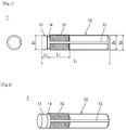
- FIG. 1 is a plan view and a side view of a vent piece according to an embodiment of the present invention
- FIG. 2 is a perspective view thereof.
- numeral 1 indicates a vent piece
- numeral 11 indicates a head part thereof
- numeral 12 indicates a trunk part thereof
- numeral 13 indicates a saw-cut
- numeral 14 indicates a vent line
- numeral 15 indicates twill knurl.
- the vent piece 1 is formed as a pillar-shaped member not having a hole in the axial direction and includes the head part 11 and the trunk part 12.
- the vent piece 1 is used in a manner of being embedded in a prepared hole for air vent provided in the inner face of a vulcanization mold for pneumatic tire. Further, the vent piece 1 is constructed such that air vent is performed through a gap formed between itself and a side face part of the prepared hole for air vent.
- the vent piece 1 according to the present embodiment is constructed from a pillar-shaped member having a simple structure.
- structural restriction like in the spring vent of the conventional art is not caused and a smaller size can be achieved. Accordingly, in whatever locations, orderly embedment and arrangement can be performed without particular restriction.
- stainless steel As the construction material for the vent piece 1, stainless steel, iron, aluminum, or the like is preferable. Among these, stainless steel is particularly preferable.
- the vent piece 1 As the shape of the vent piece 1, from the perspective of easiness in machining at the time of forming the prepared hole in the vulcanization mold and the like, a cylindrical shape is preferable. Specifically, the vent piece 1 having a cylindrical shape in which the diameter D1 of the head part 11 and the diameter D2 of the trunk part 12 are 1.4 to 2.6 mm and the overall length L1 is 6 to 14 mm is preferable.
- the gap for air vent formed between the side face part of the vent piece 1 and the side face part of the prepared hole for air vent it is sufficient that a gap capable of satisfactorily releasing air so as to suppress the occurrence of spew is formed.
- the diameter D1 of the head part 11 and the diameter D2 of the trunk part 12 described above are set up suitably within the range given above.
- the shape of the vent piece 1 is not limited to the above-mentioned cylindrical shape and may be a prism shape or another pillar shape.
- the saw-cut 13 extending in the axial direction is formed in the side face part of the vent piece 1.
- the saw-cut 13 like this is provided, even in the vent piece 1 of the same size, a passage of air is more satisfactorily ensured and hence the air vent function is improved further.
- the vent line 14 extending in the circumferential direction is formed between the head part 11 and trunk parts 12.
- the vent line 14 like this is provided, the air having passed through the gap around the head part 11 is led through the vent line 14 to the saw-cut 13.
- the passage for air is more satisfactorily ensured and hence the air vent function is improved further.
- grooves of R0.1 mm to R0.4 mm or, alternatively, of similar shapes are preferable.
- the formation of the saw-cut or the vent line is not limited to one location and may be performed at a plurality of, that is, two or more, locations. Further, in a case that passage for air is satisfactorily ensured even without the saw-cut or the vent line, the formation is not necessary.
- the twill knurl 15 is formed at least in a part of the surface of the side face part of the trunk part 12.
- the twill knurl 15 is formed in a diameter D3 that is similar to the prepared hole of the vulcanization mold in which the vent piece 1 is embedded and that is larger than the trunk part 12. Then, the twill knurl 15 prevents the vent piece 1 embedded in the vulcanization mold from falling off from the prepared hole. Further, air is satisfactorily released along a gap for air vent formed between the depressions and protrusions of the twill knurl 15 and the side face part of the prepared hole. Thus, the air vent function is improved further.
- the length L3 over which the twill knurl 15 is formed and the pitch of the twill are suitably determined with taking into consideration the embedment workability into the prepared hole of the vent piece 1, the property of preventing fall-off from the prepared hole, and the like. Specifically, a pitch of 0.3 to 0.7 mm is preferable.
- vulcanization of a pneumatic tire employing the above-mentioned vent piece is described below. Specifically, the above-mentioned vent piece 1 is embedded into the prepared hole for air vent provided in the inner face of a vulcanization mold 2 for pneumatic tire such that the head part is located on the vulcanization mold surface ( FIG. 3 ). Then, vulcanization molding of a raw cover is performed.
- the size of the vent piece can be reduced in the present embodiment.
- the vent pieces can orderly be arranged and embedded even on a narrow line 21, as shown in FIG. 4 , on which spring vents of the conventional art cannot orderly be arranged and embedded.
- the vent piece air is released through a slight gap formed between itself and the prepared hole.
- the vent piece cannot release a large amount of air per piece in comparison with the spring vent.
- the vent piece can easily and orderly be arranged at a location at which the spring vent cannot orderly be arranged.
- the number of arrangements can easily be increased so that a satisfactory amount of air can be released in the entirety.
- vent piece can be achieved by providing a prepared hole for air vent in the inner face of the vulcanization mold. Thus, when necessary, additional arrangement can be performed later.
- FIG. 5 is a diagram showing an external appearance of a pneumatic tire obtained by vulcanization molding by using a vulcanization mold in which a spring vent of the conventional art and a vent piece according to the present embodiment are employed together.
- T indicates a tire obtained by vulcanization molding
- P1 indicates a vent mark caused by the vent piece according to the present embodiment
- P2 indicates a vent mark caused by the spring vent of the conventional art.
- the vent mark P1 caused by the vent piece according to the present embodiment is of a single circle and hence is not very noticeable in the external appearance.
- the vent mark P2 caused by the spring vent is of a double circle and is hence rather noticeable in the external appearance.
- vent piece shown in FIG. 1 was embedded in the lower mold of a two-piece mold and then a tire for evaluation of size 215/45R17 SP8090 was fabricated.
- Embedment of the vent piece was performed at 24 locations on the circumference of the Maximum Flange Shield (MFS) top and at four locations on the circumference of the side part.
- MFS Maximum Flange Shield
- the external appearance was evaluated by visual observation of the fabricated tire for evaluation.
- vent piece marks were hardly noticeable and hence it has been concluded that a pneumatic tire having a remarkably orderly external appearance was obtained. Further, also in the R40 curved surface in the side face, no abnormality has been found that could cause a particular problem.
Landscapes
- Engineering & Computer Science (AREA)
- Mechanical Engineering (AREA)
- Moulds For Moulding Plastics Or The Like (AREA)
- Heating, Cooling, Or Curing Plastics Or The Like In General (AREA)
Abstract
Description
- The present invention relates to a vent piece used for performing air vent of a raw cover (an unvulcanized tire) in vulcanization molding of a pneumatic tire; and a manufacturing method for pneumatic tire in which vulcanization molding of a pneumatic tire is performed by embedding the vent piece in a vulcanization mold.
- Vulcanization molding of a pneumatic tire is performed such that: a raw cover is set in a vulcanization mold; then, a bladder arranged on the inner side of the raw cover is expanded so that the outer surface of the raw cover is pressed against the inner face of the vulcanization mold; followed by heating and pressurizing the raw cover at predetermined temperature and pressure for a predetermined time.
- In this vulcanization molding, when air remains in the inner face or the surface of the raw cover, this causes degradation in the external appearance quality serving as a product and in the durability of the pneumatic tire. Thus, for example, a method that a vent hole is provided in the vulcanization mold and then air vent is performed (e.g., Patent Document 1) and a method that a vent piece is embedded in a prepared hole formed in the mold and then air vent is performed have widely been employed.
- Nevertheless, in these methods, occurrence of spew caused by rubber extruded into the vent hole or the hole of the vent piece cannot be avoided. Among these, the spew caused by the vent hole need be removed in the manufacturing process. Further, as for the spew caused by the vent piece, when the number of occurrences increases, unpreferable external appearance is caused.
- As methods for suppressing such occurrence of spew, the method of dividing the mold into a plurality (e.g., Patent Document 2) and the method of employing a spring-shaped vent piece (a spring vent) have been proposed.
-
- Patent Document 1:
JP2873363B - Patent Document 2:
JP2003-311742A - Nevertheless, these methods have the following problems.
- That is, in the case of the method of dividing the mold into a plurality, air vent can be performed by releasing air through a gap formed between the mating surfaces of the divided molds. Nevertheless, the portion of air vent is determined in the initial design of the mold and hence cannot be added later. Further, in a case that the mold is divided into an excessively large number, a possibility arises that the mold cannot tolerate the pressurization and hence distortion is caused.
- In the case of the method of employing a spring vent, as shown in
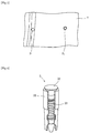
FIG. 6 , air vent can be performed by virtue of the operation of avalve element 32 and aspring 33 attached to a tube-shaped vent piece 31, and such a device can be added even later. Nevertheless, in thespring vent 3, the diameter unavoidably becomes as large as 2.0 to 4.0 mm from a structural reason. This causes restriction in the location for orderly arrangement. - Thus, an object of the present invention is to provide:
- a vent piece which can easily be added later in vulcanization molding of a pneumatic tire and is free from restriction in the location for orderly arrangement and in which occurrence of spew can satisfactorily be suppressed; and
- a manufacturing method for pneumatic tire in which vulcanization molding of a raw cover is performed by using a vulcanization mold for pneumatic tire in which the vent piece has been embedded.
- The invention described in
claim 1 is
a vent piece used in a manner of being embedded in a prepared hole for air vent provided in an inner face of a vulcanization mold for pneumatic tire, wherein: - the vent piece is composed of a pillar-shaped member not having a hole in an axial direction; and
- the vent piece is constructed such that air vent is performed through a gap formed between itself and a side face part of the prepared hole for air vent.
- The invention described in
claim 2 is
the vent piece according toclaim 1, wherein a saw-cut extending in the axial direction is formed in the side face part of the pillar-shaped member. - The invention described in
claim 3 is
the vent piece according toclaim 2, wherein a vent line in a circumferential direction is further formed in the side face part of the pillar-shaped member. - The invention described in claim 4 is
the vent piece according to any one ofclaims 1 to 3, wherein twill knurl is formed at least in a part of the side face part of the pillar-shaped member. - The invention described in claim 5 is
a manufacturing method for pneumatic tire in which vulcanization molding of a raw cover is performed by using a vulcanization mold for pneumatic tire in which the vent piece according to any one ofclaims 1 to 4 has been embedded. - According to the present invention, provided are: a vent piece which can easily be added later in vulcanization molding of a pneumatic tire and is free from restriction in the location for orderly arrangement and in which occurrence of spew can satisfactorily be suppressed; and a manufacturing method for pneumatic tire in which vulcanization molding of a raw cover is performed by using a vulcanization mold for pneumatic tire in which the vent piece has been embedded.
-
- [
FIG. 1] FIG. 1 is a plan view and a side view of a vent piece according to an embodiment of the present invention. - [
FIG. 2] FIG. 2 is a perspective view of a vent piece according to an embodiment of the present invention. - [
FIG. 3] FIG. 3 is a diagram showing a situation that a vent piece according to an embodiment of the present invention is embedded in a prepared hole of a mold. - [
FIG. 4] FIG. 4 is a diagram showing an example of arrangement locations for vent pieces according to an embodiment of the present invention. - [
FIG. 5] FIG. 5 is a diagram showing an external appearance of a pneumatic tire obtained by vulcanization molding by using a vulcanization mold in which a spring vent of the conventional art and a vent piece according to an embodiment of the present invention are employed together. - [
FIG. 6] FIG. 6 is a diagram showing a structure of a spring vent. - The present invention is described below in accordance with an embodiment with reference to the drawings.
-
FIG. 1 is a plan view and a side view of a vent piece according to an embodiment of the present invention, andFIG. 2 is a perspective view thereof. InFIGS. 1 and 2 ,numeral 1 indicates a vent piece,numeral 11 indicates a head part thereof,numeral 12 indicates a trunk part thereof,numeral 13 indicates a saw-cut,numeral 14 indicates a vent line, andnumeral 15 indicates twill knurl. - As shown in
FIGS. 1 and 2 , thevent piece 1 is formed as a pillar-shaped member not having a hole in the axial direction and includes thehead part 11 and thetrunk part 12. Thevent piece 1 is used in a manner of being embedded in a prepared hole for air vent provided in the inner face of a vulcanization mold for pneumatic tire. Further, thevent piece 1 is constructed such that air vent is performed through a gap formed between itself and a side face part of the prepared hole for air vent. - As a result, when vulcanization molding of a raw cover is performed by using the vulcanization mold in which the
vent piece 1 has been embedded, air is released through the gap for air vent formed between the side face part of thevent piece 1 and the side face part of the prepared hole for air vent. Thus, a pneumatic tire can be obtained in which occurrence of spew is suppressed. - The
vent piece 1 according to the present embodiment is constructed from a pillar-shaped member having a simple structure. Thus, structural restriction like in the spring vent of the conventional art is not caused and a smaller size can be achieved. Accordingly, in whatever locations, orderly embedment and arrangement can be performed without particular restriction. - As the construction material for the
vent piece 1, stainless steel, iron, aluminum, or the like is preferable. Among these, stainless steel is particularly preferable. - As the shape of the
vent piece 1, from the perspective of easiness in machining at the time of forming the prepared hole in the vulcanization mold and the like, a cylindrical shape is preferable. Specifically, thevent piece 1 having a cylindrical shape in which the diameter D1 of thehead part 11 and the diameter D2 of thetrunk part 12 are 1.4 to 2.6 mm and the overall length L1 is 6 to 14 mm is preferable. - Here, as for the gap for air vent formed between the side face part of the
vent piece 1 and the side face part of the prepared hole for air vent, it is sufficient that a gap capable of satisfactorily releasing air so as to suppress the occurrence of spew is formed. Thus, with taking this point into consideration, the diameter D1 of thehead part 11 and the diameter D2 of thetrunk part 12 described above are set up suitably within the range given above. - The shape of the
vent piece 1 is not limited to the above-mentioned cylindrical shape and may be a prism shape or another pillar shape. - It is preferable that the saw-cut 13 extending in the axial direction is formed in the side face part of the
vent piece 1. When the saw-cut 13 like this is provided, even in thevent piece 1 of the same size, a passage of air is more satisfactorily ensured and hence the air vent function is improved further. - Further, in the
vent piece 1, it is more preferable that thevent line 14 extending in the circumferential direction is formed between thehead part 11 andtrunk parts 12. When thevent line 14 like this is provided, the air having passed through the gap around thehead part 11 is led through thevent line 14 to the saw-cut 13. Thus, the passage for air is more satisfactorily ensured and hence the air vent function is improved further. - As the specific shapes of the saw-cut 13 and the
vent line 14, grooves of R0.1 mm to R0.4 mm or, alternatively, of similar shapes are preferable. - The formation of the saw-cut or the vent line is not limited to one location and may be performed at a plurality of, that is, two or more, locations. Further, in a case that passage for air is satisfactorily ensured even without the saw-cut or the vent line, the formation is not necessary.
- Further, it is preferable that the
twill knurl 15 is formed at least in a part of the surface of the side face part of thetrunk part 12. Thetwill knurl 15 is formed in a diameter D3 that is similar to the prepared hole of the vulcanization mold in which thevent piece 1 is embedded and that is larger than thetrunk part 12. Then, thetwill knurl 15 prevents thevent piece 1 embedded in the vulcanization mold from falling off from the prepared hole. Further, air is satisfactorily released along a gap for air vent formed between the depressions and protrusions of thetwill knurl 15 and the side face part of the prepared hole. Thus, the air vent function is improved further. - Here, the length L3 over which the
twill knurl 15 is formed and the pitch of the twill are suitably determined with taking into consideration the embedment workability into the prepared hole of thevent piece 1, the property of preventing fall-off from the prepared hole, and the like. Specifically, a pitch of 0.3 to 0.7 mm is preferable. - Next, vulcanization of a pneumatic tire employing the above-mentioned vent piece is described below. Specifically, the above-mentioned
vent piece 1 is embedded into the prepared hole for air vent provided in the inner face of avulcanization mold 2 for pneumatic tire such that the head part is located on the vulcanization mold surface (FIG. 3 ). Then, vulcanization molding of a raw cover is performed. - By virtue of this, at the time of vulcanization molding, air can satisfactorily be released through a gap for air vent formed between the side face part of the vent piece and the side face part of the prepared hole for air vent. Thus, a pneumatic tire can be obtained in which air remaining (bear) does not occur and occurrence of spew is also suppressed.
- As described above, the size of the vent piece can be reduced in the present embodiment. Thus, at that time, the vent pieces can orderly be arranged and embedded even on a
narrow line 21, as shown inFIG. 4 , on which spring vents of the conventional art cannot orderly be arranged and embedded. - Here, in the vent piece, air is released through a slight gap formed between itself and the prepared hole. Thus, there is a possibility that the vent piece cannot release a large amount of air per piece in comparison with the spring vent. However, as described above, the vent piece can easily and orderly be arranged at a location at which the spring vent cannot orderly be arranged. Thus, the number of arrangements can easily be increased so that a satisfactory amount of air can be released in the entirety.
- Further, arrangement of the vent piece can be achieved by providing a prepared hole for air vent in the inner face of the vulcanization mold. Thus, when necessary, additional arrangement can be performed later.
-
FIG. 5 is a diagram showing an external appearance of a pneumatic tire obtained by vulcanization molding by using a vulcanization mold in which a spring vent of the conventional art and a vent piece according to the present embodiment are employed together. Here, inFIG. 5 , T indicates a tire obtained by vulcanization molding, P1 indicates a vent mark caused by the vent piece according to the present embodiment, and P2 indicates a vent mark caused by the spring vent of the conventional art. - As shown in
FIG. 5 , the vent mark P1 caused by the vent piece according to the present embodiment is of a single circle and hence is not very noticeable in the external appearance. In contrast, the vent mark P2 caused by the spring vent is of a double circle and is hence rather noticeable in the external appearance. - The present invention is described below in further detail with reference to an implementation example.
- The vent piece shown in
FIG. 1 was embedded in the lower mold of a two-piece mold and then a tire for evaluation of size 215/45R17 SP8090 was fabricated. - Here, the specification of the vent piece shown in
FIG. 1 was as follows (the units are all in mm).


- Embedment of the vent piece was performed at 24 locations on the circumference of the Maximum Flange Shield (MFS) top and at four locations on the circumference of the side part. Here, the reason why a large number of vent pieces were arranged on the circumference of the MFS top was that in the MFS top, when air vent fails, air remaining (bear) definitely occurs.
- The external appearance was evaluated by visual observation of the fabricated tire for evaluation.
- As a result, vent piece marks were hardly noticeable and hence it has been concluded that a pneumatic tire having a remarkably orderly external appearance was obtained. Further, also in the R40 curved surface in the side face, no abnormality has been found that could cause a particular problem.
- Although embodiments of the present invention have been explained above, the present invention is not limited to the above-mentioned embodiments. Various changes can be added to the above-mentioned embodiments within the scope of the same as and equivalent to that of the present invention.
-
- 1, 31
- vent piece
- 2
- vulcanization mold
- 3
- spring vent
- 11
- head part
- 12
- trunk part
- 13
- saw-cut
- 14
- vent line
- 15
- twill knurl
- 21
- narrow line
- 32
- valve element
- 33
- spring
- D1
- diameter of the head part
- D2
- diameter of the trunk part
- D3
- diameter of the twill knurl
- L1
- overall length
- L2
- thickness of the head part
- L3
- length over which the twill knurl is formed
- P1, P2
- vent mark
- T
- tire
Claims (5)
- A vent piece used in a manner of being embedded in a prepared hole for air vent provided in an inner face of a vulcanization mold for pneumatic tire, wherein:the vent piece is composed of a pillar-shaped member not having a hole in an axial direction; andthe vent piece is constructed such that air vent is performed through a gap formed between itself and a side face part of the prepared hole for air vent.
- The vent piece according to claim 1, wherein a saw-cut extending in the axial direction is formed in the side face part of the pillar-shaped member.
- The vent piece according to claim 2, wherein a vent line in a circumferential direction is further formed in the side face part of the pillar-shaped member.
- The vent piece according to any one of claims 1 to 3, wherein twill knurl is formed at least in a part of the side face part of the pillar-shaped member.
- A manufacturing method for pneumatic tire in which vulcanization molding of a raw cover is performed by using a vulcanization mold for pneumatic tire in which the vent piece according to any one of claims 1 to 4 has been embedded.
Applications Claiming Priority (2)
| Application Number | Priority Date | Filing Date | Title |
|---|---|---|---|
| JP2013207863A JP6071832B2 (en) | 2013-10-03 | 2013-10-03 | Bent piece and pneumatic tire manufacturing method |
| PCT/JP2014/074345 WO2015049974A1 (en) | 2013-10-03 | 2014-09-16 | Vent piece and pneumatic tire manufacturing method |
Publications (3)
| Publication Number | Publication Date |
|---|---|
| EP3002099A1 true EP3002099A1 (en) | 2016-04-06 |
| EP3002099A4 EP3002099A4 (en) | 2017-03-01 |
| EP3002099B1 EP3002099B1 (en) | 2019-01-09 |
Family
ID=52778569
Family Applications (1)
| Application Number | Title | Priority Date | Filing Date |
|---|---|---|---|
| EP14850604.1A Active EP3002099B1 (en) | 2013-10-03 | 2014-09-16 | Vent piece and pneumatic tire manufacturing method |
Country Status (5)
| Country | Link |
|---|---|
| US (1) | US10350845B2 (en) |
| EP (1) | EP3002099B1 (en) |
| JP (1) | JP6071832B2 (en) |
| CN (1) | CN105517769B (en) |
| WO (1) | WO2015049974A1 (en) |
Families Citing this family (5)
| Publication number | Priority date | Publication date | Assignee | Title |
|---|---|---|---|---|
| KR101691330B1 (en) * | 2016-06-23 | 2016-12-29 | 홍성광 | Apparatus for air vent of tire mold |
| KR101690463B1 (en) * | 2016-07-01 | 2016-12-27 | 홍성광 | Apparatus for air vent of tire mold |
| JP2020001336A (en) * | 2018-06-29 | 2020-01-09 | Toyo Tire株式会社 | Vent sleeve for tire vulcanizing mold and tire vulcanizing mold |
| CN108748811B (en) * | 2018-08-14 | 2023-11-17 | 高密同创气门芯有限公司 | An exhaust device, its assembly method and a tire mold having the exhaust device |
| KR102567416B1 (en) * | 2021-10-19 | 2023-08-16 | 금호타이어 주식회사 | Tread shoulder ventless plug for tire vulcanizing mold |
Family Cites Families (12)
| Publication number | Priority date | Publication date | Assignee | Title |
|---|---|---|---|---|
| DE1899584U (en) * | 1964-05-29 | 1964-08-27 | Erich Lendle & Co K G | NOZZLE FOR MOLDS FOR THE MANUFACTURING OF MOLDINGS FROM PLASTICS. |
| US4795331A (en) | 1986-09-15 | 1989-01-03 | The Goodyear Tire & Rubber Company | Mold vent plug |
| JP2873363B2 (en) | 1995-07-17 | 1999-03-24 | 住友ゴム工業株式会社 | Tire mold |
| US6454361B1 (en) * | 2001-04-30 | 2002-09-24 | Desmond G. Martin | Skateboard wheel cover rim |
| JP2003311742A (en) | 2002-04-26 | 2003-11-05 | Sumitomo Rubber Ind Ltd | Tire vulcanizing mold and pneumatic tire molded thereby |
| JP4507818B2 (en) * | 2004-10-18 | 2010-07-21 | 横浜ゴム株式会社 | Tire mold and plug used for vent hole of tire mold |
| JP2006334872A (en) * | 2005-06-01 | 2006-12-14 | Bridgestone Corp | Tire vulcanization mold |
| JP2007062017A (en) * | 2005-08-29 | 2007-03-15 | Yokohama Rubber Co Ltd:The | Tire molding die, plug used for vent hole of tire molding die, and tire manufactured using this tire molding die |
| US7530803B2 (en) * | 2007-05-08 | 2009-05-12 | Bridgestone Firestone North American Tire, Llc | Insert for a tire mold vent |
| JP5291976B2 (en) * | 2008-04-21 | 2013-09-18 | 東洋ゴム工業株式会社 | Vent plug for tire vulcanization mold, tire vulcanization mold, and method for manufacturing pneumatic tire using tire vulcanization mold |
| JP4709882B2 (en) * | 2008-09-24 | 2011-06-29 | 住友ゴム工業株式会社 | Mold for tire |
| JP2010137370A (en) * | 2008-12-09 | 2010-06-24 | Bridgestone Corp | Vent piece, and vulcanizing mold including the same |
-
2013
- 2013-10-03 JP JP2013207863A patent/JP6071832B2/en active Active
-
2014
- 2014-09-16 CN CN201480048669.6A patent/CN105517769B/en active Active
- 2014-09-16 WO PCT/JP2014/074345 patent/WO2015049974A1/en not_active Ceased
- 2014-09-16 EP EP14850604.1A patent/EP3002099B1/en active Active
- 2014-09-16 US US14/902,968 patent/US10350845B2/en active Active
Non-Patent Citations (1)
| Title |
|---|
| See references of WO2015049974A1 * |
Also Published As
| Publication number | Publication date |
|---|---|
| US10350845B2 (en) | 2019-07-16 |
| US20160151989A1 (en) | 2016-06-02 |
| EP3002099B1 (en) | 2019-01-09 |
| JP2015071251A (en) | 2015-04-16 |
| CN105517769B (en) | 2019-01-25 |
| EP3002099A4 (en) | 2017-03-01 |
| WO2015049974A1 (en) | 2015-04-09 |
| JP6071832B2 (en) | 2017-02-01 |
| CN105517769A (en) | 2016-04-20 |
Similar Documents
| Publication | Publication Date | Title |
|---|---|---|
| EP3002099B1 (en) | Vent piece and pneumatic tire manufacturing method | |
| JP5613198B2 (en) | Tire vulcanization mold | |
| US10456952B2 (en) | Tire cure mold and method of manufacturing tire | |
| JP5210548B2 (en) | Tire tread vulcanization mold | |
| US9522509B2 (en) | Tire mold vent | |
| BR112015032072A2 (en) | tire comprising an improved tread | |
| CN110520285A (en) | Valve insertion piece and air bleeder valve | |
| EP3995303A4 (en) | Tire vulcanization mold and manufacturing method for tire | |
| WO2014091911A1 (en) | Tire mold | |
| BRPI0806168A2 (en) | tire, mold for vulcanizing a tire, method of fabricating a liner and die for molding a liner | |
| EP3603946A3 (en) | Tyre mold, method for manufacturing tyre, and tyre | |
| JP6317599B2 (en) | Tire vulcanization mold | |
| JP6754683B2 (en) | Tire mold and tire mold manufacturing method | |
| DE102010037785A1 (en) | Vulcanizing mold for vulcanization of vehicle tires, has vulcanizing mold segments comprising mold surfaces that includes partial shaped segments, where one of partial shaped segments is produced by laser sintering process | |
| US20170361552A1 (en) | Tire mold and vent insert having corresponding surfaces | |
| JP6397263B2 (en) | Vent piece | |
| EP3590695B8 (en) | Vulcanisation unit comprising at least one mould carrier and use and method for vulcanising a tyre for a vehicle | |
| CN102555111B (en) | Tire vulcanization mold | |
| JP2015168122A (en) | Bladder for tire vulcanization and method for measuring distortion of bladder for tire vulcanization | |
| JP6107249B2 (en) | Tire vulcanizing bladder and bladder unit | |
| JP3217843U (en) | Tire vulcanization mold equipment | |
| JP6742594B2 (en) | Tire vulcanization mold | |
| JP6804953B2 (en) | Manufacturing method of tire vulcanization mold and pneumatic tire | |
| JP2007062270A (en) | Mold for vulcanizing tire and manufacturing method of it | |
| JP6130762B2 (en) | Tire molding die and tire molding method |
Legal Events
| Date | Code | Title | Description |
|---|---|---|---|
| PUAI | Public reference made under article 153(3) epc to a published international application that has entered the european phase |
Free format text: ORIGINAL CODE: 0009012 |
|
| 17P | Request for examination filed |
Effective date: 20151230 |
|
| AK | Designated contracting states |
Kind code of ref document: A1 Designated state(s): AL AT BE BG CH CY CZ DE DK EE ES FI FR GB GR HR HU IE IS IT LI LT LU LV MC MK MT NL NO PL PT RO RS SE SI SK SM TR |
|
| AX | Request for extension of the european patent |
Extension state: BA ME |
|
| DAX | Request for extension of the european patent (deleted) | ||
| A4 | Supplementary search report drawn up and despatched |
Effective date: 20170126 |
|
| RIC1 | Information provided on ipc code assigned before grant |
Ipc: B29D 30/06 20060101ALI20170120BHEP Ipc: B29C 35/02 20060101ALI20170120BHEP Ipc: B29L 30/00 20060101ALI20170120BHEP Ipc: B29C 33/10 20060101AFI20170120BHEP |
|
| STAA | Information on the status of an ep patent application or granted ep patent |
Free format text: STATUS: EXAMINATION IS IN PROGRESS |
|
| 17Q | First examination report despatched |
Effective date: 20180206 |
|
| GRAP | Despatch of communication of intention to grant a patent |
Free format text: ORIGINAL CODE: EPIDOSNIGR1 |
|
| STAA | Information on the status of an ep patent application or granted ep patent |
Free format text: STATUS: GRANT OF PATENT IS INTENDED |
|
| INTG | Intention to grant announced |
Effective date: 20180828 |
|
| GRAS | Grant fee paid |
Free format text: ORIGINAL CODE: EPIDOSNIGR3 |
|
| GRAA | (expected) grant |
Free format text: ORIGINAL CODE: 0009210 |
|
| STAA | Information on the status of an ep patent application or granted ep patent |
Free format text: STATUS: THE PATENT HAS BEEN GRANTED |
|
| AK | Designated contracting states |
Kind code of ref document: B1 Designated state(s): AL AT BE BG CH CY CZ DE DK EE ES FI FR GB GR HR HU IE IS IT LI LT LU LV MC MK MT NL NO PL PT RO RS SE SI SK SM TR |
|
| REG | Reference to a national code |
Ref country code: GB Ref legal event code: FG4D |
|
| REG | Reference to a national code |
Ref country code: CH Ref legal event code: EP Ref country code: AT Ref legal event code: REF Ref document number: 1086742 Country of ref document: AT Kind code of ref document: T Effective date: 20190115 |
|
| REG | Reference to a national code |
Ref country code: IE Ref legal event code: FG4D |
|
| REG | Reference to a national code |
Ref country code: DE Ref legal event code: R096 Ref document number: 602014039750 Country of ref document: DE |
|
| REG | Reference to a national code |
Ref country code: NL Ref legal event code: MP Effective date: 20190109 |
|
| REG | Reference to a national code |
Ref country code: LT Ref legal event code: MG4D |
|
| PG25 | Lapsed in a contracting state [announced via postgrant information from national office to epo] |
Ref country code: NL Free format text: LAPSE BECAUSE OF FAILURE TO SUBMIT A TRANSLATION OF THE DESCRIPTION OR TO PAY THE FEE WITHIN THE PRESCRIBED TIME-LIMIT Effective date: 20190109 |
|
| REG | Reference to a national code |
Ref country code: AT Ref legal event code: MK05 Ref document number: 1086742 Country of ref document: AT Kind code of ref document: T Effective date: 20190109 |
|
| PG25 | Lapsed in a contracting state [announced via postgrant information from national office to epo] |
Ref country code: LT Free format text: LAPSE BECAUSE OF FAILURE TO SUBMIT A TRANSLATION OF THE DESCRIPTION OR TO PAY THE FEE WITHIN THE PRESCRIBED TIME-LIMIT Effective date: 20190109 Ref country code: PL Free format text: LAPSE BECAUSE OF FAILURE TO SUBMIT A TRANSLATION OF THE DESCRIPTION OR TO PAY THE FEE WITHIN THE PRESCRIBED TIME-LIMIT Effective date: 20190109 Ref country code: SE Free format text: LAPSE BECAUSE OF FAILURE TO SUBMIT A TRANSLATION OF THE DESCRIPTION OR TO PAY THE FEE WITHIN THE PRESCRIBED TIME-LIMIT Effective date: 20190109 Ref country code: NO Free format text: LAPSE BECAUSE OF FAILURE TO SUBMIT A TRANSLATION OF THE DESCRIPTION OR TO PAY THE FEE WITHIN THE PRESCRIBED TIME-LIMIT Effective date: 20190409 Ref country code: ES Free format text: LAPSE BECAUSE OF FAILURE TO SUBMIT A TRANSLATION OF THE DESCRIPTION OR TO PAY THE FEE WITHIN THE PRESCRIBED TIME-LIMIT Effective date: 20190109 Ref country code: PT Free format text: LAPSE BECAUSE OF FAILURE TO SUBMIT A TRANSLATION OF THE DESCRIPTION OR TO PAY THE FEE WITHIN THE PRESCRIBED TIME-LIMIT Effective date: 20190509 Ref country code: FI Free format text: LAPSE BECAUSE OF FAILURE TO SUBMIT A TRANSLATION OF THE DESCRIPTION OR TO PAY THE FEE WITHIN THE PRESCRIBED TIME-LIMIT Effective date: 20190109 |
|
| PG25 | Lapsed in a contracting state [announced via postgrant information from national office to epo] |
Ref country code: GR Free format text: LAPSE BECAUSE OF FAILURE TO SUBMIT A TRANSLATION OF THE DESCRIPTION OR TO PAY THE FEE WITHIN THE PRESCRIBED TIME-LIMIT Effective date: 20190410 Ref country code: IS Free format text: LAPSE BECAUSE OF FAILURE TO SUBMIT A TRANSLATION OF THE DESCRIPTION OR TO PAY THE FEE WITHIN THE PRESCRIBED TIME-LIMIT Effective date: 20190509 Ref country code: BG Free format text: LAPSE BECAUSE OF FAILURE TO SUBMIT A TRANSLATION OF THE DESCRIPTION OR TO PAY THE FEE WITHIN THE PRESCRIBED TIME-LIMIT Effective date: 20190409 Ref country code: RS Free format text: LAPSE BECAUSE OF FAILURE TO SUBMIT A TRANSLATION OF THE DESCRIPTION OR TO PAY THE FEE WITHIN THE PRESCRIBED TIME-LIMIT Effective date: 20190109 Ref country code: LV Free format text: LAPSE BECAUSE OF FAILURE TO SUBMIT A TRANSLATION OF THE DESCRIPTION OR TO PAY THE FEE WITHIN THE PRESCRIBED TIME-LIMIT Effective date: 20190109 Ref country code: HR Free format text: LAPSE BECAUSE OF FAILURE TO SUBMIT A TRANSLATION OF THE DESCRIPTION OR TO PAY THE FEE WITHIN THE PRESCRIBED TIME-LIMIT Effective date: 20190109 |
|
| REG | Reference to a national code |
Ref country code: DE Ref legal event code: R097 Ref document number: 602014039750 Country of ref document: DE |
|
| PG25 | Lapsed in a contracting state [announced via postgrant information from national office to epo] |
Ref country code: AL Free format text: LAPSE BECAUSE OF FAILURE TO SUBMIT A TRANSLATION OF THE DESCRIPTION OR TO PAY THE FEE WITHIN THE PRESCRIBED TIME-LIMIT Effective date: 20190109 Ref country code: DK Free format text: LAPSE BECAUSE OF FAILURE TO SUBMIT A TRANSLATION OF THE DESCRIPTION OR TO PAY THE FEE WITHIN THE PRESCRIBED TIME-LIMIT Effective date: 20190109 Ref country code: SK Free format text: LAPSE BECAUSE OF FAILURE TO SUBMIT A TRANSLATION OF THE DESCRIPTION OR TO PAY THE FEE WITHIN THE PRESCRIBED TIME-LIMIT Effective date: 20190109 Ref country code: EE Free format text: LAPSE BECAUSE OF FAILURE TO SUBMIT A TRANSLATION OF THE DESCRIPTION OR TO PAY THE FEE WITHIN THE PRESCRIBED TIME-LIMIT Effective date: 20190109 Ref country code: IT Free format text: LAPSE BECAUSE OF FAILURE TO SUBMIT A TRANSLATION OF THE DESCRIPTION OR TO PAY THE FEE WITHIN THE PRESCRIBED TIME-LIMIT Effective date: 20190109 Ref country code: CZ Free format text: LAPSE BECAUSE OF FAILURE TO SUBMIT A TRANSLATION OF THE DESCRIPTION OR TO PAY THE FEE WITHIN THE PRESCRIBED TIME-LIMIT Effective date: 20190109 Ref country code: AT Free format text: LAPSE BECAUSE OF FAILURE TO SUBMIT A TRANSLATION OF THE DESCRIPTION OR TO PAY THE FEE WITHIN THE PRESCRIBED TIME-LIMIT Effective date: 20190109 Ref country code: RO Free format text: LAPSE BECAUSE OF FAILURE TO SUBMIT A TRANSLATION OF THE DESCRIPTION OR TO PAY THE FEE WITHIN THE PRESCRIBED TIME-LIMIT Effective date: 20190109 |
|
| PLBE | No opposition filed within time limit |
Free format text: ORIGINAL CODE: 0009261 |
|
| STAA | Information on the status of an ep patent application or granted ep patent |
Free format text: STATUS: NO OPPOSITION FILED WITHIN TIME LIMIT |
|
| PG25 | Lapsed in a contracting state [announced via postgrant information from national office to epo] |
Ref country code: SM Free format text: LAPSE BECAUSE OF FAILURE TO SUBMIT A TRANSLATION OF THE DESCRIPTION OR TO PAY THE FEE WITHIN THE PRESCRIBED TIME-LIMIT Effective date: 20190109 |
|
| 26N | No opposition filed |
Effective date: 20191010 |
|
| PG25 | Lapsed in a contracting state [announced via postgrant information from national office to epo] |
Ref country code: SI Free format text: LAPSE BECAUSE OF FAILURE TO SUBMIT A TRANSLATION OF THE DESCRIPTION OR TO PAY THE FEE WITHIN THE PRESCRIBED TIME-LIMIT Effective date: 20190109 |
|
| PG25 | Lapsed in a contracting state [announced via postgrant information from national office to epo] |
Ref country code: TR Free format text: LAPSE BECAUSE OF FAILURE TO SUBMIT A TRANSLATION OF THE DESCRIPTION OR TO PAY THE FEE WITHIN THE PRESCRIBED TIME-LIMIT Effective date: 20190109 |
|
| PG25 | Lapsed in a contracting state [announced via postgrant information from national office to epo] |
Ref country code: MC Free format text: LAPSE BECAUSE OF FAILURE TO SUBMIT A TRANSLATION OF THE DESCRIPTION OR TO PAY THE FEE WITHIN THE PRESCRIBED TIME-LIMIT Effective date: 20190109 |
|
| REG | Reference to a national code |
Ref country code: CH Ref legal event code: PL |
|
| PG25 | Lapsed in a contracting state [announced via postgrant information from national office to epo] |
Ref country code: CH Free format text: LAPSE BECAUSE OF NON-PAYMENT OF DUE FEES Effective date: 20190930 Ref country code: LU Free format text: LAPSE BECAUSE OF NON-PAYMENT OF DUE FEES Effective date: 20190916 Ref country code: LI Free format text: LAPSE BECAUSE OF NON-PAYMENT OF DUE FEES Effective date: 20190930 Ref country code: IE Free format text: LAPSE BECAUSE OF NON-PAYMENT OF DUE FEES Effective date: 20190916 |
|
| REG | Reference to a national code |
Ref country code: BE Ref legal event code: MM Effective date: 20190930 |
|
| PG25 | Lapsed in a contracting state [announced via postgrant information from national office to epo] |
Ref country code: BE Free format text: LAPSE BECAUSE OF NON-PAYMENT OF DUE FEES Effective date: 20190930 |
|
| GBPC | Gb: european patent ceased through non-payment of renewal fee |
Effective date: 20190916 |
|
| PG25 | Lapsed in a contracting state [announced via postgrant information from national office to epo] |
Ref country code: GB Free format text: LAPSE BECAUSE OF NON-PAYMENT OF DUE FEES Effective date: 20190916 |
|
| PG25 | Lapsed in a contracting state [announced via postgrant information from national office to epo] |
Ref country code: CY Free format text: LAPSE BECAUSE OF FAILURE TO SUBMIT A TRANSLATION OF THE DESCRIPTION OR TO PAY THE FEE WITHIN THE PRESCRIBED TIME-LIMIT Effective date: 20190109 |
|
| PG25 | Lapsed in a contracting state [announced via postgrant information from national office to epo] |
Ref country code: MT Free format text: LAPSE BECAUSE OF FAILURE TO SUBMIT A TRANSLATION OF THE DESCRIPTION OR TO PAY THE FEE WITHIN THE PRESCRIBED TIME-LIMIT Effective date: 20190109 Ref country code: HU Free format text: LAPSE BECAUSE OF FAILURE TO SUBMIT A TRANSLATION OF THE DESCRIPTION OR TO PAY THE FEE WITHIN THE PRESCRIBED TIME-LIMIT; INVALID AB INITIO Effective date: 20140916 |
|
| PG25 | Lapsed in a contracting state [announced via postgrant information from national office to epo] |
Ref country code: MK Free format text: LAPSE BECAUSE OF FAILURE TO SUBMIT A TRANSLATION OF THE DESCRIPTION OR TO PAY THE FEE WITHIN THE PRESCRIBED TIME-LIMIT Effective date: 20190109 |
|
| PGFP | Annual fee paid to national office [announced via postgrant information from national office to epo] |
Ref country code: DE Payment date: 20250730 Year of fee payment: 12 |
|
| PGFP | Annual fee paid to national office [announced via postgrant information from national office to epo] |
Ref country code: FR Payment date: 20250808 Year of fee payment: 12 |