EP3001940B1 - Vacuum cleaner - Google Patents
Vacuum cleaner Download PDFInfo
- Publication number
- EP3001940B1 EP3001940B1 EP15187700.8A EP15187700A EP3001940B1 EP 3001940 B1 EP3001940 B1 EP 3001940B1 EP 15187700 A EP15187700 A EP 15187700A EP 3001940 B1 EP3001940 B1 EP 3001940B1
- Authority
- EP
- European Patent Office
- Prior art keywords
- voltage
- battery
- vacuum cleaner
- suction motor
- controller
- Prior art date
- Legal status (The legal status is an assumption and is not a legal conclusion. Google has not performed a legal analysis and makes no representation as to the accuracy of the status listed.)
- Active
Links
- 239000000428 dust Substances 0.000 claims description 16
- 238000007599 discharging Methods 0.000 claims description 14
- 238000004140 cleaning Methods 0.000 description 10
- 238000010586 diagram Methods 0.000 description 4
- 238000001514 detection method Methods 0.000 description 3
- 238000012986 modification Methods 0.000 description 3
- 230000004048 modification Effects 0.000 description 3
- 238000000926 separation method Methods 0.000 description 3
- 238000009499 grossing Methods 0.000 description 2
- 239000003990 capacitor Substances 0.000 description 1
- 239000003086 colorant Substances 0.000 description 1
- 230000005669 field effect Effects 0.000 description 1
- 230000006870 function Effects 0.000 description 1
- 238000009413 insulation Methods 0.000 description 1
- 239000012212 insulator Substances 0.000 description 1
- 229910044991 metal oxide Inorganic materials 0.000 description 1
- 150000004706 metal oxides Chemical class 0.000 description 1
- 238000000034 method Methods 0.000 description 1
- 239000004065 semiconductor Substances 0.000 description 1
- 239000000126 substance Substances 0.000 description 1
Images


Classifications
-
- A—HUMAN NECESSITIES
- A47—FURNITURE; DOMESTIC ARTICLES OR APPLIANCES; COFFEE MILLS; SPICE MILLS; SUCTION CLEANERS IN GENERAL
- A47L—DOMESTIC WASHING OR CLEANING; SUCTION CLEANERS IN GENERAL
- A47L9/00—Details or accessories of suction cleaners, e.g. mechanical means for controlling the suction or for effecting pulsating action; Storing devices specially adapted to suction cleaners or parts thereof; Carrying-vehicles specially adapted for suction cleaners
- A47L9/28—Installation of the electric equipment, e.g. adaptation or attachment to the suction cleaner; Controlling suction cleaners by electric means
- A47L9/2868—Arrangements for power supply of vacuum cleaners or the accessories thereof
- A47L9/2884—Details of arrangements of batteries or their installation
-
- A—HUMAN NECESSITIES
- A47—FURNITURE; DOMESTIC ARTICLES OR APPLIANCES; COFFEE MILLS; SPICE MILLS; SUCTION CLEANERS IN GENERAL
- A47L—DOMESTIC WASHING OR CLEANING; SUCTION CLEANERS IN GENERAL
- A47L5/00—Structural features of suction cleaners
- A47L5/12—Structural features of suction cleaners with power-driven air-pumps or air-compressors, e.g. driven by motor vehicle engine vacuum
-
- A—HUMAN NECESSITIES
- A47—FURNITURE; DOMESTIC ARTICLES OR APPLIANCES; COFFEE MILLS; SPICE MILLS; SUCTION CLEANERS IN GENERAL
- A47L—DOMESTIC WASHING OR CLEANING; SUCTION CLEANERS IN GENERAL
- A47L9/00—Details or accessories of suction cleaners, e.g. mechanical means for controlling the suction or for effecting pulsating action; Storing devices specially adapted to suction cleaners or parts thereof; Carrying-vehicles specially adapted for suction cleaners
- A47L9/28—Installation of the electric equipment, e.g. adaptation or attachment to the suction cleaner; Controlling suction cleaners by electric means
- A47L9/2805—Parameters or conditions being sensed
- A47L9/2831—Motor parameters, e.g. motor load or speed
-
- A—HUMAN NECESSITIES
- A47—FURNITURE; DOMESTIC ARTICLES OR APPLIANCES; COFFEE MILLS; SPICE MILLS; SUCTION CLEANERS IN GENERAL
- A47L—DOMESTIC WASHING OR CLEANING; SUCTION CLEANERS IN GENERAL
- A47L9/00—Details or accessories of suction cleaners, e.g. mechanical means for controlling the suction or for effecting pulsating action; Storing devices specially adapted to suction cleaners or parts thereof; Carrying-vehicles specially adapted for suction cleaners
- A47L9/28—Installation of the electric equipment, e.g. adaptation or attachment to the suction cleaner; Controlling suction cleaners by electric means
- A47L9/2836—Installation of the electric equipment, e.g. adaptation or attachment to the suction cleaner; Controlling suction cleaners by electric means characterised by the parts which are controlled
- A47L9/2842—Suction motors or blowers
-
- A—HUMAN NECESSITIES
- A47—FURNITURE; DOMESTIC ARTICLES OR APPLIANCES; COFFEE MILLS; SPICE MILLS; SUCTION CLEANERS IN GENERAL
- A47L—DOMESTIC WASHING OR CLEANING; SUCTION CLEANERS IN GENERAL
- A47L9/00—Details or accessories of suction cleaners, e.g. mechanical means for controlling the suction or for effecting pulsating action; Storing devices specially adapted to suction cleaners or parts thereof; Carrying-vehicles specially adapted for suction cleaners
- A47L9/28—Installation of the electric equipment, e.g. adaptation or attachment to the suction cleaner; Controlling suction cleaners by electric means
- A47L9/2868—Arrangements for power supply of vacuum cleaners or the accessories thereof
- A47L9/2878—Dual-powered vacuum cleaners, i.e. devices which can be operated with mains power supply or by batteries
-
- G—PHYSICS
- G05—CONTROLLING; REGULATING
- G05B—CONTROL OR REGULATING SYSTEMS IN GENERAL; FUNCTIONAL ELEMENTS OF SUCH SYSTEMS; MONITORING OR TESTING ARRANGEMENTS FOR SUCH SYSTEMS OR ELEMENTS
- G05B11/00—Automatic controllers
- G05B11/01—Automatic controllers electric
-
- H—ELECTRICITY
- H01—ELECTRIC ELEMENTS
- H01M—PROCESSES OR MEANS, e.g. BATTERIES, FOR THE DIRECT CONVERSION OF CHEMICAL ENERGY INTO ELECTRICAL ENERGY
- H01M10/00—Secondary cells; Manufacture thereof
- H01M10/42—Methods or arrangements for servicing or maintenance of secondary cells or secondary half-cells
- H01M10/46—Accumulators structurally combined with charging apparatus
-
- Y—GENERAL TAGGING OF NEW TECHNOLOGICAL DEVELOPMENTS; GENERAL TAGGING OF CROSS-SECTIONAL TECHNOLOGIES SPANNING OVER SEVERAL SECTIONS OF THE IPC; TECHNICAL SUBJECTS COVERED BY FORMER USPC CROSS-REFERENCE ART COLLECTIONS [XRACs] AND DIGESTS
- Y02—TECHNOLOGIES OR APPLICATIONS FOR MITIGATION OR ADAPTATION AGAINST CLIMATE CHANGE
- Y02E—REDUCTION OF GREENHOUSE GAS [GHG] EMISSIONS, RELATED TO ENERGY GENERATION, TRANSMISSION OR DISTRIBUTION
- Y02E60/00—Enabling technologies; Technologies with a potential or indirect contribution to GHG emissions mitigation
- Y02E60/10—Energy storage using batteries
Definitions
- a vacuum cleaner is disclosed herein.
- vacuum cleaners are devices that suck air including dust by using a suction force generated by a suction motor mounted on an inside of a main body and then filter the dust in the inside of the main body.
- Such vacuum cleaners are classified into manual cleaners and robotic cleaners.
- Manual cleaners are cleaners that a user has to perform cleaning manually
- robotic cleaners are cleaners that perform cleaning automatically while traveling an area to be cleaned.
- the manual cleaners may be classified into canister type cleaners in which a main body and a suction nozzle are separated from each other and are connected using a connection tube, and upright type cleaners in which a suction nozzle is combined with a main body.
- Korean Patent Application Publication No. 10-2006-0118796 (published on November 24, 2006) discloses a power cord outlet for a cleaner.
- a cord reel assembly is provided in a main body, and a power cord is connected to an outlet so that power may be supplied to the main body.
- the cleaner since the cleaner receives power from the cord reel assembly, the cleaner may be moved by a length of a cord wound on the cord reel assembly when cleaning is performed using the cleaner. Thus, there is a limitation in performing cleaning.
- JP 2004 57367 A discloses a chargeable type vacuum cleaner made to automatically stop discharge of the secondary batteries when the voltage has a specified voltage or lower by detecting the voltage of the batteries for supplying power to the electric fan.
- a control means for controlling the electric fan is provided with an invalidation part which blocks the reception of a detection signal inputted from a battery voltage detection circuit for a specified period of time based on operation of starting the electric fan at an operating part. Even when the battery voltage temporarily drops down below the reference voltage immediately after the start of the operation, the invalidation part prevents the control means from stopping the discharge of the secondary batteries responding to the drop in the voltage to or below the reference voltage.
- WO 2014/000 794 A1 discloses a vacuum cleaner comprising a motor, a battery source for providing power to the motor, a voltage measuring unit for measuring a voltage over the motor, and a current measuring unit for measuring a current flowing through the motor. Further, the vacuum cleaner comprises a control unit for controlling, based on the measured voltage and the measured current, the power provided to the motor from the battery source to attain a target motor power value during a specified time period from start-up of the motor.
- the present disclosure is directed to a vacuum cleaner that is capable of being conveniently moved.
- the present disclosure is also directed to a vacuum cleaner in which a lifetime of a battery is extended.
- a vacuum cleaner including: a cleaner main body comprising a suction motor that generates a suction force; a suction unit arranged to communication with the cleaner main body and receives air and dust; a battery arranged to supply power to the suction motor; a battery management system (BMS) arranged to detect a status of the battery; and a controller arranged to control an operation of the suction motor, wherein, if a voltage of the battery detected by the BMS reaches (e.g. is less than or equal to) a reference voltage, the controller stops the suction motor, and the reference voltage is changeable. It may be said that the controller is arranged to change the reference voltage or the controller changes the reference voltage or the reference voltage is selected by the controller.
- BMS battery management system
- the battery may comprise a plurality of battery cells, and the BMS may manage discharging of each of the plurality of battery cells so that power is capable of being supplied to the suction motor from each of the plurality of battery cells.
- the BMS may detect a voltage of each of the plurality of battery cells, and the controller may stop the suction motor when a voltage of one or more of the plurality of battery cells is less than or equal to a reference voltage.
- the BMS may detect a voltage each of the plurality of battery cells, and the controller may stop the suction motor if a voltage of all of the plurality of battery cells is less than or equal to a reference voltage.
- the controller may change the reference voltage from a first voltage to a second voltage that is lower than the first voltage.
- the first voltage may be a voltage that is 75% or more of the voltage of all of the battery cells or a voltage that is 75% or more of a maximum voltage of each of the plurality of battery cells.
- the second voltage may be a voltage that is 45% or more of the voltage of all of the battery cells or a voltage that is 45% or more of the maximum voltage of each of the plurality of battery cells.
- the controller may determine that the reference voltage changing condition is satisfied.
- the controller may determine that the reference voltage changing condition is satisfied.
- the controller may determine that the reference voltage changing condition is satisfied.
- the controller may determine that the reference voltage changing condition of the battery is satisfied.
- the controller may determine that the reference voltage changing condition is satisfied.
- the controller may determine that the reference voltage changing condition of the battery is satisfied.
- the vacuum cleaner may further comprise a display unit that displays information regarding the necessity of charging of the battery, or an informing unit from which a voice is output, when the suction motor is stopped.
- Fig. 1 is a perspective view of a vacuum cleaner according to an embodiment
- Fig. 2 is an exploded perspective view of a main body of the vacuum cleaner according to an embodiment
- Fig. 3 is a block diagram of a configuration of the vacuum cleaner according to an embodiment.
- a vacuum cleaner 1 may include a cleaner main body 10 including a suction motor 160 that generates a suction force, and a suction device 20 that guides air including dust toward the cleaner main body 10.
- the suction device 20 may include a suction unit 21 for inhaling dust on a surface to be cleaned, for example, on a floor, and connection units 22, 23, and 24 for connecting the suction unit 21 to the cleaner main body 10.
- connection units 22, 23, and 24 may include an extension tube 24 connected to the suction unit 21, a handle 22 connected to the extension tube 24, and a suction hose 23 that connects the handle 22 to the cleaner main body 10.
- the vacuum cleaner 1 may further include a dust separation unit (not shown) that separates air and dust sucked by the suction device 20 from each other, and a dust canister 110 that stores dust separated by the dust separation unit.
- the dust canister 110 may be separably mounted on the cleaner main body 10.
- the dust separation unit may be manufactured as an element separated from the dust canister 110 or may form one module with the dust canister 110.
- the vacuum cleaner 1 may include a battery 120 that supplies power for operating the suction motor 160, a charging device 140 for charging the battery 120, and a power cord 30 that is separably connected to the cleaner main body 10 and supplies commercially available power to the cleaner main body 10.
- the power cord 30 may include a plug 31 connected to an outlet, and a cord connector 32 connected to the cleaner main body 10.
- the cleaner main body 10 may include a main body connector 102 to which the cord connector 32 is connected.
- the cleaner main body 10 may include a first body 101 and a second body 103 coupled to a lower side of the first body 101. Wheels 105 may be coupled to both sides of the second body 103, respectively.
- the suction motor 160, the battery 120, and the charging device 140 may be installed in the second body 103.
- the suction motor 160 may be protected by a motor housing 162. That is, the suction motor 160 may be accommodated in the motor housing 162.
- the battery 120 may be positioned lateral to the motor housing 162, i.e., lateral to the suction motor 160 to increase spatial efficiency.
- the suction motor 160 and the battery 120 may be positioned between a plurality of wheels 105.
- the battery 120 may be positioned between one among the plurality of wheels 105 and the suction motor 160.
- the charging device 140 may be disposed to be spaced apart from the battery 120.
- the battery 120 may also be provided at the suction unit 21.
- the connection units 22, 23, and 24 may perform a function of transferring power of the battery 120 to the cleaner main body 10.
- the dust canister 110 may be separably coupled to the first body 101.
- the main body connector 102 may be provided at the first body 101.
- the battery 120 includes a plurality of battery cells.
- the plurality of battery cells may include a chargeable/dischargeable secondary battery.
- the plurality of battery cells may be connected in series.
- a maximum charging voltage (that is the sum of voltages of the plurality of battery cells) that may be charged in the battery 120 has a value that exceeds 42.4 V, in one example.
- the maximum charging voltage of the battery 120 may be greater than or equal to 84.8 V.
- the charging device 140 performs rectification and smoothing operations, receives a commercially available alternating current (AC) voltage, and converts the commercially available AC voltage into a direct current (DC) voltage.
- the charging device 140 supplies the converted DC voltage to the battery 120.
- the charging device 140 converts 220 V of commercially available AC voltage into a DC voltage that exceeds 42.4 V (drops a voltage) and supplies the converted DC voltage to the battery 120.
- the charging device 140 may include a transformer 141 that transforms an input AC voltage, and an AC-DC converter 142 that converts an AC voltage output from the transformer 141 into a DC voltage.
- the DC voltage output from the AC-DC converter 142 may exceed 42.4 V.
- the transformer 141 may transform the DC voltage output from the AC-DC converter 142. In this case, the DC voltage output from the transformer 141 may exceed 42.4 V.
- the charging device 140 may not include a transformer, and a circuit for preventing the DC voltage output from the AC-DC converter 142 from being transformed into an AC voltage may also be provided. That is, the AC-DC converter 142 may be an insulation type converter. In the current embodiment, an AC-DC converter having a well-known configuration may be used and thus, a detailed description thereof will be omitted.
- the suction motor 160 may be a brush-less direct current (BLDC) motor, for example.
- a maximum output of the suction motor 160 may be greater than or equal to 600W, for example.
- a current is required to be greater than or equal to at least 14.15 A so that the suction motor 160 having a high output may be operated.
- a configuration of a circuit required to drive the suction motor 160 is complicated.
- a minimum current required to operate the suction motor 160 may be smaller than approximately 7.1 A.
- the configuration of the circuit required to drive the suction motor 160 is simplified.
- the DC voltage that exceeds 42.4 V is output from the charging device 140, and the maximum charging voltage of the battery 120 is greater than or equal to 84.8 V.
- the suction motor 160 may have a high output.
- a suction force of the vacuum cleaner 1 may be increased so that cleaning performance may be improved.
- the power cord 30 may be connected to the vacuum cleaner 1 only when the battery 120 is being charged, and when cleaning is performed using the vacuum cleaner 1, the power cord 30 may be separated from the vacuum cleaner 1 and may be advantageously used so that a degree of freedom of mobility of the vacuum cleaner 1 may be improved.
- the vacuum cleaner 1 does not include a cord reel and receives power from the battery 120, a movement distance of the vacuum cleaner 1 is not limited, and while the vacuum cleaner 1 is moved, the vacuum cleaner 1 does not need to ride over a cord wound on the cord reel or to be moved while arranging the cord so that the vacuum cleaner 1 may be smoothly moved.
- the battery 120 is electrically connected to the main body connector 102 and the maximum charging voltage of the battery 120 is greater than or equal to 84.8 V, if no transformer 141 is provided, contacting the main body connector 102 may be dangerous to a user.
- the charging device 140 since the charging device 140 includes the transformer 141, the transformer 141 serves as an insulator so that the user's safety may be improved.
- the vacuum cleaner 1 may further include a battery management system (BMS) 130.
- BMS 130 may detect a status of each of the plurality of battery cells and may transmit the result of detection to a controller 150.
- the BMS 130 may detect a voltage of each of the plurality of battery cells.
- the BMS 130 may maintain a uniform voltage between the plurality of battery cells when each of the plurality of battery cells is charged or discharged. That is, the BMS 130 may manage discharging of each of the plurality of battery cells so that power may be supplied to the suction motor 160 from each of the plurality of battery cells.
- the controller 150 may control the suction motor 160 and may control an operation of the suction motor 160 based on a voltage of the battery 120.
- the vacuum cleaner 1 may further include a user interface 170. Operation instructions of the vacuum cleaner 1 may be input through the user interface 170, and the user interface 170 may display operation information or status information of the vacuum cleaner 1.
- the user interface 170 may be provided at one or more of the handle 22 and the cleaner main body 10.
- the user interface 170 may be provided in a shape in which an input unit and a display unit are integrally formed, or may include an input unit and a display unit separately.
- the user interface 170 may include an informing unit from which a voice is output.
- Power on, a cleaning mode, and an intensity of the suction force of the vacuum cleaner 1 may be selected using the input unit.
- the display unit may display at least information regarding the remaining amount of the battery 120.
- the intensity of the suction force may be set stepwise to strong (this being a case in which the suction force is the maximum), medium, and weak (this being a case in which the suction force is the minimum), and the intensity of the suction force of the suction motor 160 may be selected through the input unit.
- the intensity of the suction force has been described to be controlled in three steps. However, it will be noted that the number of steps for classifying the intensity of the suction force is not limited.
- the controller 150 may determine a time of stopping the suction motor 160 based on the remaining amount of the battery 120. Controlling of the suction motor 160 will be described below.
- the controller 150 may control the display unit to display information regarding the necessity of charging of the battery 120 when the remaining amount of the battery 120 reaches a reference voltage.
- the reference voltage may be stored in a memory 180.
- the display unit may display the remaining amount of the battery 120 continuously or stepwise.
- the display unit may display the remaining amount of the battery 120 in the form of numbers, symbols or graphs.
- the display unit may include a plurality of light-emitting units and may display the remaining amount of the battery 120 by changing the number of turned on units among the plurality of light-emitting units.
- the display unit may display the remaining amount of the battery 120 by changing colors of lights irradiated from the plurality of light-emitting units.
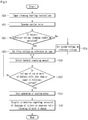
- Fig. 4 is a view illustrating controlling of a suction motor according to the number of times of battery usage according to an embodiment.
- cleaning starting instructions may be input through the user interface 170, and the intensity of the suction force of the suction motor 160 may be selected through the user interface 170 (S11).
- the controller 150 operates the suction motor 160 with the selected intensity of the suction force of the suction motor 160 (S12).
- Power is supplied to the suction motor 160 from the battery 120.
- the controller 150 determines whether a condition on which a reference voltage of the battery 120 is changed, is satisfied (S13).
- the controller 150 may determine that the reference voltage changing condition is satisfied when the number of times of usage (the number of charging or discharging cycles) of the battery 120 exceeds a reference number.
- the number of times of usage of the battery 120 may be stored in the memory 180.
- the controller 150 may determine that the reference voltage changing condition is satisfied when an accumulated usage time (for example, an accumulated discharging time) of the battery 120 exceeds a reference accumulated time.
- an accumulated usage time for example, an accumulated discharging time
- a discharging time when the battery 120 is discharged, may be accumulated and stored in the memory 180.
- the controller 150 may determine that the reference voltage changing condition is satisfied when a voltage reduction rate according to the discharging time is larger than a reference rate during discharging of the battery 120.
- the voltage reduction rate according to the discharging time of the battery 120 during the previous cleaning operation may be stored in the memory 180, and the controller 150 may compare the voltage reduction rate according to the discharging time of the battery 120 stored in the memory 180 with the reference rate.
- the controller 150 may determine that the reference voltage changing condition of the battery 120 is satisfied when a voltage increase rate according to the charging time is smaller than the reference rate during charging of the battery 120.
- the voltage increase rate according to the charging time of the battery 120 during the previous battery charging operation may be stored in the memory 180, and the controller 150 may compare the voltage increase rate according to the charging time of the battery 120 stored in the memory 180 with the reference rate.
- the controller 150 may determine that the reference voltage changing condition of the battery 120 is satisfied when a charging time during which a predetermined amount of current charges the battery 120 is longer than a reference charging time during charging of the battery 120. In this case, the charging time during which the predetermined amount of current charges the battery 120 during the previous battery charging operation is stored in the memory 180, and the controller 150 may compare the charging time when the predetermined amount of current of the battery 120 is charged stored in the memory 180 with the reference charging time.
- the controller 150 may determine that the reference voltage changing condition of the battery 120 is satisfied when a one-time available time of the battery 120 is less than or equal to a reference usage time during discharging of the battery 120.
- the one-time available time of the battery 120 during the previous cleaning operation is stored in the memory 180, and the controller 150 may compare the available time of the battery 120 stored in the memory 180 with the reference usage time.
- the available time of the battery 120 is a time required until a voltage of the battery 120 reaches a reference voltage (a first voltage).
- the controller 150 sets the first voltage as the reference voltage when the reference voltage changing condition of the battery 120 is not satisfied (S14).
- the controller 150 sets a second voltage as the reference voltage when the reference voltage changing condition of the battery 120 is satisfied (S15).
- the first voltage may be selected from a voltage that is 70% or more of a maximum voltage of each battery cell. For example, when the maximum voltage of each battery cell is 4.2 V, the first voltage may be greater than or equal to 2.94 V.
- the second voltage that is lower than the first voltage may be selected from a voltage that is 45% or more of the maximum voltage of each battery cell. For example, when the maximum voltage of each battery cell is 4.2 V, the second voltage may be greater than or equal to 1.89 V.
- the remaining amount of the battery 120 i.e., a voltage of each of the plurality of battery cells is detected by the BMS 130, and the detected voltage is transmitted to the controller 150 (S16).
- the controller 150 determines whether a voltage of one or more of the plurality of battery cells is less than or equal to the reference voltage (S17).
- the controller 150 may stop an operation of the suction motor 160 (S18).
- the display unit may display information regarding the necessity of charging of the battery 120, or the informing unit may generate a voice informing of the need to charge (S19).
- the controller 150 may also stop the operation of the suction motor 160.
- the first voltage may be selected from a voltage that is 70% or more of a maximum voltage of all of the battery cells.
- the maximum voltage of each battery cell is 4.2 V and the number of battery cells is N
- the first voltage may be selected from a voltage that is greater than or equal to (4.2 X N) X 0.7 V.
- the second voltage may be selected from a voltage that is 45% or more of the maximum voltage of all of the battery cells. For example, when the maximum voltage of each battery cell is 4.2 V and the number of battery cells is N, the second voltage may be selected from a voltage that is greater than or equal to (4.2 X N) X 0.45 V.
- Fig. 5 is a view illustrating an available time of the suction motor according to the number of times of battery usage.
- the vertical axis represents a usage time ratio and a usage time of a battery when an available time of the battery as a new product is 100
- the horizontal axis represents the number of times of battery usage (the number of battery charging cycles).
- the battery available time when the battery is used in the state in which the battery is fully charged may be increased compared to a case in which the reference voltage is not changed. Also, as the battery available time is increased, the lifetime of the battery may be increased approximately 2-fold.
- Fig. 6 is a perspective view of a vacuum cleaner according to another embodiment
- Fig. 7 is a block diagram of a configuration of the vacuum cleaner illustrated in Fig. 6 .
- a vacuum cleaner 2 may further include a cleaner main body 10 and a charging device 40 that is separably connected to the cleaner main body 10 and performs charging of the battery 120.
- the charging device 40 may include a power cord 41 connected to an outlet and a charging device connector 42 connected to the cleaner main body 10.
- the cleaner main body 10 may include a main body connector 102 to which the charging device connector 42 is connected.
- the charging device 40 performs rectification and smoothing operations, receives a commercially available AC voltage, and converts the commercially available AC voltage into a DC voltage.
- the charging device 40 supplies the converted DC voltage to the cleaner main body 10.
- the charging device 40 converts 220 V of commercially available AC voltage into a DC voltage that is less than or equal to 42.4 V (drops a voltage) and supplies the converted DC voltage to the cleaner main body 10.
- the cleaner main body 10 may further include a boosting device that boosts a voltage by receiving the DC voltage that is less than or equal to 42.4 V from the charging device 40.
- a boost converter 210 is used as an example of the boosting device.
- a configuration of the boosting device is not limited.
- the DC voltage that is less than or equal to 42.4 V input to the boost converter 210 is boosted by two times or more so that a voltage that is greater than or equal to 84.8 V may be charged in the battery 120.
- the boost converter 210 may include an inductor, a diode, a capacitor, and a switching element.
- the switching element is repeatedly turned on/off at a high speed by control of the controller 150 so that the boost converter 210 may boost an input voltage.
- the switching element may be configured of a metal oxide semiconductor field effect transistor (MOSFET).
- MOSFET metal oxide semiconductor field effect transistor
- embodiments are not limited thereto, and the switching element may also be configured of a bipolar junction transistor (BJT) or an insulated gate bipolar transistor (IGBT).
- BJT bipolar junction transistor
- IGBT insulated gate bipolar transistor
- a transformer may be additionally provided between the boosting device and the battery 120.
- the main body connector 102 may be insulated, and if the transformer is provided, the transformer serves as an insulating device. Thus, the main body connector 102 may not be insulated.
- the reference voltage is set to two steps. However, unlike this, the reference voltage may also be set to three or more steps. That is, one or more third voltages having a value between the first voltage and the second voltage may also be set as the reference voltage.
- a canister type cleaner has been described as a cleaner.
- the present disclosure may be applied to an upright type cleaner.
- a battery that supplies power to a suction motor may be provided at a suction unit or a cleaner main body.
- the above-described charging device or power cord may also be provided at the suction unit or the cleaner main body.
Description
- A vacuum cleaner is disclosed herein.
- In general, vacuum cleaners are devices that suck air including dust by using a suction force generated by a suction motor mounted on an inside of a main body and then filter the dust in the inside of the main body.
- Such vacuum cleaners are classified into manual cleaners and robotic cleaners. Manual cleaners are cleaners that a user has to perform cleaning manually, and robotic cleaners are cleaners that perform cleaning automatically while traveling an area to be cleaned.
- The manual cleaners may be classified into canister type cleaners in which a main body and a suction nozzle are separated from each other and are connected using a connection tube, and upright type cleaners in which a suction nozzle is combined with a main body.
- Korean Patent Application Publication No.
10-2006-0118796 - In the literature, a cord reel assembly is provided in a main body, and a power cord is connected to an outlet so that power may be supplied to the main body.
- In the literature, since the cleaner receives power from the cord reel assembly, the cleaner may be moved by a length of a cord wound on the cord reel assembly when cleaning is performed using the cleaner. Thus, there is a limitation in performing cleaning.
-
JP 2004 57367 A -
WO 2014/000 794 A1 discloses a vacuum cleaner comprising a motor, a battery source for providing power to the motor, a voltage measuring unit for measuring a voltage over the motor, and a current measuring unit for measuring a current flowing through the motor. Further, the vacuum cleaner comprises a control unit for controlling, based on the measured voltage and the measured current, the power provided to the motor from the battery source to attain a target motor power value during a specified time period from start-up of the motor. - The present disclosure is directed to a vacuum cleaner that is capable of being conveniently moved.
- The present disclosure is also directed to a vacuum cleaner in which a lifetime of a battery is extended.
- Aspects of an invention are defined in the appended independent claims.
- There is provided a vacuum cleaner including: a cleaner main body comprising a suction motor that generates a suction force; a suction unit arranged to communication with the cleaner main body and receives air and dust; a battery arranged to supply power to the suction motor; a battery management system (BMS) arranged to detect a status of the battery; and a controller arranged to control an operation of the suction motor, wherein, if a voltage of the battery detected by the BMS reaches (e.g. is less than or equal to) a reference voltage, the controller stops the suction motor, and the reference voltage is changeable. It may be said that the controller is arranged to change the reference voltage or the controller changes the reference voltage or the reference voltage is selected by the controller.
- The battery may comprise a plurality of battery cells, and the BMS may manage discharging of each of the plurality of battery cells so that power is capable of being supplied to the suction motor from each of the plurality of battery cells.
- The BMS may detect a voltage of each of the plurality of battery cells, and the controller may stop the suction motor when a voltage of one or more of the plurality of battery cells is less than or equal to a reference voltage.
- The BMS may detect a voltage each of the plurality of battery cells, and the controller may stop the suction motor if a voltage of all of the plurality of battery cells is less than or equal to a reference voltage.
- If a condition on which the reference voltage is changed is satisfied, the controller may change the reference voltage from a first voltage to a second voltage that is lower than the first voltage.
- The first voltage may be a voltage that is 75% or more of the voltage of all of the battery cells or a voltage that is 75% or more of a maximum voltage of each of the plurality of battery cells.
- The second voltage may be a voltage that is 45% or more of the voltage of all of the battery cells or a voltage that is 45% or more of the maximum voltage of each of the plurality of battery cells.
- If the number of times of usage of the battery exceeds a reference number, the controller may determine that the reference voltage changing condition is satisfied.
- If an accumulated usage time of the battery exceeds a reference accumulated time, the controller may determine that the reference voltage changing condition is satisfied.
- If a voltage reduction rate according to a discharging time is larger than a reference rate during discharging of the battery, the controller may determine that the reference voltage changing condition is satisfied.
- If a voltage increase rate according to a charging time is smaller than a reference rate during charging of the battery, the controller may determine that the reference voltage changing condition of the battery is satisfied.
- If a charging time during which a predetermined amount of current charges the battery is longer than a reference charging time during charging of the battery, the controller may determine that the reference voltage changing condition is satisfied.
- If a one-time available time of the battery is less than or equal to a reference usage time during discharging of the battery, the controller may determine that the reference voltage changing condition of the battery is satisfied.
- The vacuum cleaner may further comprise a display unit that displays information regarding the necessity of charging of the battery, or an informing unit from which a voice is output, when the suction motor is stopped.
- The details of one or more embodiments are set forth in the accompanying drawings and the description below. Other features will be apparent from the description and drawings, and from the claims.
- Embodiments will be described in detail with reference to the following drawings in which like reference numerals refer to like elements, and wherein:
-
Fig. 1 is a perspective view of a vacuum cleaner according to an embodiment; -
Fig. 2 is an exploded perspective view of a main body of the vacuum cleaner according to an embodiment; -
Fig. 3 is a block diagram of a configuration of the vacuum cleaner according to an embodiment; -
Fig. 4 is a flowchart illustrating a method of controlling a suction motor according to the number of times of battery usage according to an embodiment; -
Fig. 5 is a view illustrating an available time of the suction motor according to the number of times of battery usage; -
Fig. 6 is a perspective view of a vacuum cleaner according to another embodiment; and -
Fig. 7 is a block diagram of a configuration of the vacuum cleaner illustrated inFig. 6 . - Reference will now be made in detail to the embodiments, examples of which are illustrated in the accompanying drawings.
- In the following detailed description of the preferred embodiments, reference is made to the accompanying drawings that form a part hereof, and in which is shown by way of illustration specific preferred embodiments. These embodiments are described in sufficient detail to enable those skilled in the art to practice the subject-matter, and it is understood that other embodiments may be utilized and that logical structural, mechanical, electrical, and chemical changes may be made without departing from the scope of the claims. To avoid detail not necessary to enable those skilled in the art to practice the subject-matter, the description may omit certain information known to those skilled in the art. The following detailed description is, therefore, not to be taken in a limiting sense.
- Also, in the description of embodiments, terms such as "first," "second," "A," "B," "(a)," "(b)" or the like may be used herein when describing components. Each of these terms is not used to define an essence, order or sequence of a corresponding component but used merely to distinguish the corresponding component from other component(s). It should be noted that if it is described in the specification that one component is "connected," "coupled" or "joined" to another component, the former may be directly "connected," "coupled," and "joined" to the latter or "connected", "coupled", and "joined" to the latter via another component.
-
Fig. 1 is a perspective view of a vacuum cleaner according to an embodiment, andFig. 2 is an exploded perspective view of a main body of the vacuum cleaner according to an embodiment, andFig. 3 is a block diagram of a configuration of the vacuum cleaner according to an embodiment. - Referring to
Figs. 1 through 3 , avacuum cleaner 1 according to an embodiment may include a cleanermain body 10 including asuction motor 160 that generates a suction force, and asuction device 20 that guides air including dust toward the cleanermain body 10. - The
suction device 20 may include asuction unit 21 for inhaling dust on a surface to be cleaned, for example, on a floor, andconnection units suction unit 21 to the cleanermain body 10. - The
connection units extension tube 24 connected to thesuction unit 21, ahandle 22 connected to theextension tube 24, and asuction hose 23 that connects thehandle 22 to the cleanermain body 10. - The
vacuum cleaner 1 may further include a dust separation unit (not shown) that separates air and dust sucked by thesuction device 20 from each other, and adust canister 110 that stores dust separated by the dust separation unit. Thedust canister 110 may be separably mounted on the cleanermain body 10. The dust separation unit may be manufactured as an element separated from thedust canister 110 or may form one module with thedust canister 110. - The
vacuum cleaner 1 may include abattery 120 that supplies power for operating thesuction motor 160, acharging device 140 for charging thebattery 120, and apower cord 30 that is separably connected to the cleanermain body 10 and supplies commercially available power to the cleanermain body 10. - The
power cord 30 may include aplug 31 connected to an outlet, and acord connector 32 connected to the cleanermain body 10. The cleanermain body 10 may include amain body connector 102 to which thecord connector 32 is connected. - The cleaner
main body 10 may include afirst body 101 and asecond body 103 coupled to a lower side of thefirst body 101.Wheels 105 may be coupled to both sides of thesecond body 103, respectively. - The
suction motor 160, thebattery 120, and thecharging device 140 may be installed in thesecond body 103. Thesuction motor 160 may be protected by amotor housing 162. That is, thesuction motor 160 may be accommodated in themotor housing 162. - In this case, the
battery 120 may be positioned lateral to themotor housing 162, i.e., lateral to thesuction motor 160 to increase spatial efficiency. - The
suction motor 160 and thebattery 120 may be positioned between a plurality ofwheels 105. Thebattery 120 may be positioned between one among the plurality ofwheels 105 and thesuction motor 160. The chargingdevice 140 may be disposed to be spaced apart from thebattery 120. - In another example, the
battery 120 may also be provided at thesuction unit 21. However, in this case, theconnection units battery 120 to the cleanermain body 10. - The
dust canister 110 may be separably coupled to thefirst body 101. Themain body connector 102 may be provided at thefirst body 101. - The
battery 120 includes a plurality of battery cells. The plurality of battery cells may include a chargeable/dischargeable secondary battery. The plurality of battery cells may be connected in series. - In an embodiment, a maximum charging voltage (that is the sum of voltages of the plurality of battery cells) that may be charged in the
battery 120 has a value that exceeds 42.4 V, in one example. For example, the maximum charging voltage of thebattery 120 may be greater than or equal to 84.8 V. - The charging
device 140 performs rectification and smoothing operations, receives a commercially available alternating current (AC) voltage, and converts the commercially available AC voltage into a direct current (DC) voltage. The chargingdevice 140 supplies the converted DC voltage to thebattery 120. For example, the chargingdevice 140 converts 220 V of commercially available AC voltage into a DC voltage that exceeds 42.4 V (drops a voltage) and supplies the converted DC voltage to thebattery 120. - The charging
device 140 may include atransformer 141 that transforms an input AC voltage, and an AC-DC converter 142 that converts an AC voltage output from thetransformer 141 into a DC voltage. In this case, the DC voltage output from the AC-DC converter 142 may exceed 42.4 V. - In another example, the
transformer 141 may transform the DC voltage output from the AC-DC converter 142. In this case, the DC voltage output from thetransformer 141 may exceed 42.4 V. - In still another example, the charging
device 140 may not include a transformer, and a circuit for preventing the DC voltage output from the AC-DC converter 142 from being transformed into an AC voltage may also be provided. That is, the AC-DC converter 142 may be an insulation type converter. In the current embodiment, an AC-DC converter having a well-known configuration may be used and thus, a detailed description thereof will be omitted. - In the current embodiment, the
suction motor 160 may be a brush-less direct current (BLDC) motor, for example. A maximum output of thesuction motor 160 may be greater than or equal to 600W, for example. - When a maximum charging voltage of the
battery 120 is less than or equal to 42.4 V, a current is required to be greater than or equal to at least 14.15 A so that thesuction motor 160 having a high output may be operated. Thus, a configuration of a circuit required to drive thesuction motor 160 is complicated. - However, according to the current embodiment, since a maximum voltage charged in the
battery 120 is greater than or equal to 84.8 V, a minimum current required to operate thesuction motor 160 may be smaller than approximately 7.1 A. Thus, the configuration of the circuit required to drive thesuction motor 160 is simplified. - According to the current embodiment, the DC voltage that exceeds 42.4 V is output from the charging
device 140, and the maximum charging voltage of thebattery 120 is greater than or equal to 84.8 V. Thus, thesuction motor 160 may have a high output. Thus, a suction force of thevacuum cleaner 1 may be increased so that cleaning performance may be improved. - Also, the
power cord 30 may be connected to thevacuum cleaner 1 only when thebattery 120 is being charged, and when cleaning is performed using thevacuum cleaner 1, thepower cord 30 may be separated from thevacuum cleaner 1 and may be advantageously used so that a degree of freedom of mobility of thevacuum cleaner 1 may be improved. - That is, since the
vacuum cleaner 1 does not include a cord reel and receives power from thebattery 120, a movement distance of thevacuum cleaner 1 is not limited, and while thevacuum cleaner 1 is moved, thevacuum cleaner 1 does not need to ride over a cord wound on the cord reel or to be moved while arranging the cord so that thevacuum cleaner 1 may be smoothly moved. - Also, in the current embodiment, since the
battery 120 is electrically connected to themain body connector 102 and the maximum charging voltage of thebattery 120 is greater than or equal to 84.8 V, if notransformer 141 is provided, contacting themain body connector 102 may be dangerous to a user. However, in the current embodiment, since thecharging device 140 includes thetransformer 141, thetransformer 141 serves as an insulator so that the user's safety may be improved. - The
vacuum cleaner 1 may further include a battery management system (BMS) 130. TheBMS 130 may detect a status of each of the plurality of battery cells and may transmit the result of detection to acontroller 150. - In one example, the
BMS 130 may detect a voltage of each of the plurality of battery cells. - Also, the
BMS 130 may maintain a uniform voltage between the plurality of battery cells when each of the plurality of battery cells is charged or discharged. That is, theBMS 130 may manage discharging of each of the plurality of battery cells so that power may be supplied to thesuction motor 160 from each of the plurality of battery cells. - The
controller 150 may control thesuction motor 160 and may control an operation of thesuction motor 160 based on a voltage of thebattery 120. - Meanwhile, the
vacuum cleaner 1 may further include auser interface 170. Operation instructions of thevacuum cleaner 1 may be input through theuser interface 170, and theuser interface 170 may display operation information or status information of thevacuum cleaner 1. - The
user interface 170 may be provided at one or more of thehandle 22 and the cleanermain body 10. Theuser interface 170 may be provided in a shape in which an input unit and a display unit are integrally formed, or may include an input unit and a display unit separately. Theuser interface 170 may include an informing unit from which a voice is output. - Power on, a cleaning mode, and an intensity of the suction force of the
vacuum cleaner 1 may be selected using the input unit. The display unit may display at least information regarding the remaining amount of thebattery 120. - In one example, the intensity of the suction force may be set stepwise to strong (this being a case in which the suction force is the maximum), medium, and weak (this being a case in which the suction force is the minimum), and the intensity of the suction force of the
suction motor 160 may be selected through the input unit. In the present specification, the intensity of the suction force has been described to be controlled in three steps. However, it will be noted that the number of steps for classifying the intensity of the suction force is not limited. - The
controller 150 may determine a time of stopping thesuction motor 160 based on the remaining amount of thebattery 120. Controlling of thesuction motor 160 will be described below. - The
controller 150 may control the display unit to display information regarding the necessity of charging of thebattery 120 when the remaining amount of thebattery 120 reaches a reference voltage. The reference voltage may be stored in amemory 180. - In another example, the display unit may display the remaining amount of the
battery 120 continuously or stepwise. For example, the display unit may display the remaining amount of thebattery 120 in the form of numbers, symbols or graphs. Alternatively, the display unit may include a plurality of light-emitting units and may display the remaining amount of thebattery 120 by changing the number of turned on units among the plurality of light-emitting units. Alternatively, the display unit may display the remaining amount of thebattery 120 by changing colors of lights irradiated from the plurality of light-emitting units. -
Fig. 4 is a view illustrating controlling of a suction motor according to the number of times of battery usage according to an embodiment. - Referring to
Fig. 4 , cleaning starting instructions may be input through theuser interface 170, and the intensity of the suction force of thesuction motor 160 may be selected through the user interface 170 (S11). - The
controller 150 operates thesuction motor 160 with the selected intensity of the suction force of the suction motor 160 (S12). - Power is supplied to the
suction motor 160 from thebattery 120. - When the
suction motor 160 operates, thecontroller 150 determines whether a condition on which a reference voltage of thebattery 120 is changed, is satisfied (S13). - The
controller 150 may determine that the reference voltage changing condition is satisfied when the number of times of usage (the number of charging or discharging cycles) of thebattery 120 exceeds a reference number. The number of times of usage of thebattery 120 may be stored in thememory 180. - In another example, the
controller 150 may determine that the reference voltage changing condition is satisfied when an accumulated usage time (for example, an accumulated discharging time) of thebattery 120 exceeds a reference accumulated time. A discharging time when thebattery 120 is discharged, may be accumulated and stored in thememory 180. - In still another example, the
controller 150 may determine that the reference voltage changing condition is satisfied when a voltage reduction rate according to the discharging time is larger than a reference rate during discharging of thebattery 120. In this case, the voltage reduction rate according to the discharging time of thebattery 120 during the previous cleaning operation may be stored in thememory 180, and thecontroller 150 may compare the voltage reduction rate according to the discharging time of thebattery 120 stored in thememory 180 with the reference rate. - In yet another example, the
controller 150 may determine that the reference voltage changing condition of thebattery 120 is satisfied when a voltage increase rate according to the charging time is smaller than the reference rate during charging of thebattery 120. In this case, the voltage increase rate according to the charging time of thebattery 120 during the previous battery charging operation may be stored in thememory 180, and thecontroller 150 may compare the voltage increase rate according to the charging time of thebattery 120 stored in thememory 180 with the reference rate. - In yet another example, the
controller 150 may determine that the reference voltage changing condition of thebattery 120 is satisfied when a charging time during which a predetermined amount of current charges thebattery 120 is longer than a reference charging time during charging of thebattery 120. In this case, the charging time during which the predetermined amount of current charges thebattery 120 during the previous battery charging operation is stored in thememory 180, and thecontroller 150 may compare the charging time when the predetermined amount of current of thebattery 120 is charged stored in thememory 180 with the reference charging time. - In yet another example, the
controller 150 may determine that the reference voltage changing condition of thebattery 120 is satisfied when a one-time available time of thebattery 120 is less than or equal to a reference usage time during discharging of thebattery 120. In this case, the one-time available time of thebattery 120 during the previous cleaning operation is stored in thememory 180, and thecontroller 150 may compare the available time of thebattery 120 stored in thememory 180 with the reference usage time. Here, the available time of thebattery 120 is a time required until a voltage of thebattery 120 reaches a reference voltage (a first voltage). - As a result of the determination in operation S13, the
controller 150 sets the first voltage as the reference voltage when the reference voltage changing condition of thebattery 120 is not satisfied (S14). - On the other hand, as a result of the determination in operation S13, the
controller 150 sets a second voltage as the reference voltage when the reference voltage changing condition of thebattery 120 is satisfied (S15). - In the current embodiment, the first voltage may be selected from a voltage that is 70% or more of a maximum voltage of each battery cell. For example, when the maximum voltage of each battery cell is 4.2 V, the first voltage may be greater than or equal to 2.94 V.
- The second voltage that is lower than the first voltage may be selected from a voltage that is 45% or more of the maximum voltage of each battery cell. For example, when the maximum voltage of each battery cell is 4.2 V, the second voltage may be greater than or equal to 1.89 V.
- While the
battery 120 is discharged, the remaining amount of thebattery 120, i.e., a voltage of each of the plurality of battery cells is detected by theBMS 130, and the detected voltage is transmitted to the controller 150 (S16). - The
controller 150 determines whether a voltage of one or more of the plurality of battery cells is less than or equal to the reference voltage (S17). - As a result of the determination in operation S17, if the voltage of one or more of the plurality of battery cells is less than or equal to the reference voltage, the
controller 150 may stop an operation of the suction motor 160 (S18). - If the operation of the
suction motor 160 is stopped, the display unit may display information regarding the necessity of charging of thebattery 120, or the informing unit may generate a voice informing of the need to charge (S19). - In another example, in operation S17, if a voltage of all of the battery cells is less than or equal to the reference voltage, the
controller 150 may also stop the operation of thesuction motor 160. - Even in this case, in
Fig. 4 , the first voltage may be selected from a voltage that is 70% or more of a maximum voltage of all of the battery cells. For example, when the maximum voltage of each battery cell is 4.2 V and the number of battery cells is N, the first voltage may be selected from a voltage that is greater than or equal to (4.2 X N) X 0.7 V. - Also, in
Fig. 4 , the second voltage may be selected from a voltage that is 45% or more of the maximum voltage of all of the battery cells. For example, when the maximum voltage of each battery cell is 4.2 V and the number of battery cells is N, the second voltage may be selected from a voltage that is greater than or equal to (4.2 X N) X 0.45 V. -
Fig. 5 is a view illustrating an available time of the suction motor according to the number of times of battery usage. - In
Fig. 5 , the vertical axis represents a usage time ratio and a usage time of a battery when an available time of the battery as a new product is 100, and the horizontal axis represents the number of times of battery usage (the number of battery charging cycles). - Referring to
Fig. 5 , as the number of times of battery usage is increased, the battery available time when the battery is used in a state in which the battery is fully charged, is reduced. - In this case, by changing the reference voltage for determining the time of stopping the operation of the suction motor from the first voltage into the second voltage, i.e., by reducing the reference voltage, the battery available time when the battery is used in the state in which the battery is fully charged, may be increased compared to a case in which the reference voltage is not changed. Also, as the battery available time is increased, the lifetime of the battery may be increased approximately 2-fold.
-
Fig. 6 is a perspective view of a vacuum cleaner according to another embodiment, andFig. 7 is a block diagram of a configuration of the vacuum cleaner illustrated inFig. 6 . - The other portions of the current embodiment are the same as those of the previous embodiment except that a charging device is separably connected to the vacuum cleaner. Thus, hereinafter, only characteristic portions of the current embodiment will be described.
- Referring to
Figs. 6 and7 , avacuum cleaner 2 according to the current embodiment may further include a cleanermain body 10 and a chargingdevice 40 that is separably connected to the cleanermain body 10 and performs charging of thebattery 120. - The charging
device 40 may include apower cord 41 connected to an outlet and acharging device connector 42 connected to the cleanermain body 10. The cleanermain body 10 may include amain body connector 102 to which thecharging device connector 42 is connected. - The charging
device 40 performs rectification and smoothing operations, receives a commercially available AC voltage, and converts the commercially available AC voltage into a DC voltage. The chargingdevice 40 supplies the converted DC voltage to the cleanermain body 10. For example, the chargingdevice 40 converts 220 V of commercially available AC voltage into a DC voltage that is less than or equal to 42.4 V (drops a voltage) and supplies the converted DC voltage to the cleanermain body 10. - Thus, since the DC voltage that is less than or equal to 42.4 V is output from the charging
device connector 42 of the chargingdevice 40, there is no problem in the user's safety even when no insulating device is provided at thecharging device connector 42. Of course, an insulating device may be provided at thecharging device connector 42. - In the current embodiment, in order to operate the
suction motor 160 having a high output by using a voltage charged in thebattery 120, the cleanermain body 10 may further include a boosting device that boosts a voltage by receiving the DC voltage that is less than or equal to 42.4 V from the chargingdevice 40. - In
Fig. 7 , aboost converter 210 is used as an example of the boosting device. However, it will be noted that, in the current embodiment, a configuration of the boosting device is not limited. - In the current embodiment, the DC voltage that is less than or equal to 42.4 V input to the
boost converter 210 is boosted by two times or more so that a voltage that is greater than or equal to 84.8 V may be charged in thebattery 120. - The
boost converter 210 may include an inductor, a diode, a capacitor, and a switching element. The switching element is repeatedly turned on/off at a high speed by control of thecontroller 150 so that theboost converter 210 may boost an input voltage. - In this case, the switching element may be configured of a metal oxide semiconductor field effect transistor (MOSFET). However, embodiments are not limited thereto, and the switching element may also be configured of a bipolar junction transistor (BJT) or an insulated gate bipolar transistor (IGBT).
- In another example, a transformer may be additionally provided between the boosting device and the
battery 120. - If no transformer is provided, the
main body connector 102 may be insulated, and if the transformer is provided, the transformer serves as an insulating device. Thus, themain body connector 102 may not be insulated. - As described above, the reference voltage is set to two steps. However, unlike this, the reference voltage may also be set to three or more steps. That is, one or more third voltages having a value between the first voltage and the second voltage may also be set as the reference voltage.
- As described above, a canister type cleaner has been described as a cleaner. However, the present disclosure may be applied to an upright type cleaner. In this case, a battery that supplies power to a suction motor may be provided at a suction unit or a cleaner main body. Also, the above-described charging device or power cord may also be provided at the suction unit or the cleaner main body.
- Although embodiments have been described with reference to a number of illustrative embodiments thereof, it should be understood that numerous other modifications and embodiments can be devised by those skilled in the art that will fall within the scope of the appended claims. More particularly, various variations and modifications are possible in the component parts and/or arrangements of the subject combination arrangement within the scope of the appended claims. In addition to variations and modifications in the component parts and/or arrangements, alternative uses will also be apparent to those skilled in the art.
Claims (7)
- A vacuum cleaner comprising:a cleaner main body (10) comprising a suction motor (160) arranged to generate a suction force;a suction unit arranged to communicate with the cleaner main body (10) and receive air and dust;a battery (120) arranged to supply power to the suction motor (160);a battery management system "BMS" (130) arranged to detect a status of the battery (120); anda controller (150) arranged to control an operation of the suction motor (160),wherein the controller (150) is arranged to stop the suction motor (160) if a voltage of the battery (120) detected by the BMS (130) reaches a reference voltage, andwherein the controller (150) is arranged to change the reference voltage from a first voltage to a second voltage if a condition is satisfied, characterized in that the condition is that the number of times of usage of the battery (120) exceeds a reference number, that an accumulated usage time of the battery (120) exceeds a reference accumulated time, that a voltage reduction rate is greater than a reference reduction rate during discharging of the battery (120), that a voltage increase rate is less than a reference increase rate during charging of the battery (120), that a charging time during which a predetermined amount of current charges the battery (120) is greater than a reference charging time during charging of the battery (120), or that an available usage time of the battery (120) is less than or equal to a reference usage time; and optionallywherein the controller (150) is arranged to determine whether the condition is satisfied and wherein the second voltage is lower than the first voltage.
- The vacuum cleaner according to claim 1, wherein the battery (120) comprises a plurality of battery cells, and the BMS (130) is arranged to manage discharge of each of the plurality of battery cells so that each of the plurality of battery cells is capable of supplying power to the suction motor (160).
- The vacuum cleaner according to claim 2, wherein the BMS (130) is arranged to detect a voltage of each of the plurality of battery cells, and the controller (150) is arranged to stop the suction motor (160) if a voltage of one or more of the plurality of battery cells is less than or equal to the reference voltage.
- The vacuum cleaner according to claim 2, wherein the BMS (130) is arranged to detect a voltage of each of the plurality of battery cells, and the controller (150) is arranged to stop the suction motor (160) if a voltage of all of the plurality of battery cells is less than or equal to the reference voltage.
- The vacuum cleaner according to any preceding claim, wherein the first voltage is 75% or more of the sum of the maximum voltage of all of the battery cells, or 75% or more of a maximum voltage of each battery cell.
- The vacuum cleaner according to claim 5, wherein the second voltage is 45% or more of the sum of the maximum voltage of all of the battery cells, or 45% or more of the maximum voltage of each battery cell.
- The vacuum cleaner according to any preceding claim, further comprising a display unit arranged to display information regarding the necessity to charge the battery (120), and/or an informing unit arranged to output a sound, when the suction motor (160) is stopped.
Applications Claiming Priority (1)
| Application Number | Priority Date | Filing Date | Title |
|---|---|---|---|
| KR1020140132547A KR101645808B1 (en) | 2014-10-01 | 2014-10-01 | Vacuum cleaner |
Publications (2)
| Publication Number | Publication Date |
|---|---|
| EP3001940A1 EP3001940A1 (en) | 2016-04-06 |
| EP3001940B1 true EP3001940B1 (en) | 2020-08-26 |
Family
ID=54251401
Family Applications (1)
| Application Number | Title | Priority Date | Filing Date |
|---|---|---|---|
| EP15187700.8A Active EP3001940B1 (en) | 2014-10-01 | 2015-09-30 | Vacuum cleaner |
Country Status (4)
| Country | Link |
|---|---|
| US (1) | US11213178B2 (en) |
| EP (1) | EP3001940B1 (en) |
| KR (1) | KR101645808B1 (en) |
| CN (1) | CN105476542A (en) |
Families Citing this family (12)
| Publication number | Priority date | Publication date | Assignee | Title |
|---|---|---|---|---|
| JP6850088B2 (en) * | 2016-08-05 | 2021-03-31 | 東芝ライフスタイル株式会社 | Vacuum cleaner |
| KR20180079962A (en) | 2017-01-03 | 2018-07-11 | 삼성전자주식회사 | Robot cleaner and method for controlling thereof |
| KR102415120B1 (en) * | 2017-08-16 | 2022-06-30 | 삼성에스디아이 주식회사 | battery pack and vacuum cleaner including the same |
| US11510541B2 (en) * | 2017-11-20 | 2022-11-29 | Tailos, Inc. | Battery apparatus for a robot, methods, and applications |
| JP7120772B2 (en) * | 2018-02-15 | 2022-08-17 | 東芝ライフスタイル株式会社 | vacuum cleaner |
| US11013387B2 (en) | 2018-05-31 | 2021-05-25 | Techtronic Floor Care Technology Limited | Vacuum cleaner |
| CN108711910A (en) * | 2018-06-13 | 2018-10-26 | 芜湖金智王机械设备有限公司 | The charging reminding method of sweeper |
| CN110537874A (en) * | 2018-11-02 | 2019-12-06 | 添可智能科技有限公司 | Dust collector display device and dust collector |
| GB2582348B (en) * | 2019-03-20 | 2021-09-08 | Dyson Technology Ltd | Vacuum cleaner |
| GB2582349B (en) * | 2019-03-20 | 2021-09-15 | Dyson Technology Ltd | Vacuum cleaner |
| WO2022031612A1 (en) * | 2020-08-03 | 2022-02-10 | Techtronic Cordless Gp | Floor cleaner with a low power mode |
| KR20230138352A (en) * | 2022-03-23 | 2023-10-05 | 엘지전자 주식회사 | Cleaner |
Family Cites Families (36)
| Publication number | Priority date | Publication date | Assignee | Title |
|---|---|---|---|---|
| JP2606842B2 (en) | 1987-05-30 | 1997-05-07 | 株式会社東芝 | Electric vacuum cleaner |
| EP0601999A1 (en) | 1987-12-15 | 1994-06-15 | Hitachi, Ltd. | Vacuum cleaner |
| DE69015557D1 (en) | 1989-10-18 | 1995-02-09 | Hitachi Ltd | Vacuum cleaner and method for regulating the same. |
| JPH0595861A (en) | 1991-10-07 | 1993-04-20 | Matsushita Electric Ind Co Ltd | Floor nozzle of vacuum cleaner |
| US6448732B1 (en) * | 1999-08-10 | 2002-09-10 | Pacific Steamex Cleaning Systems, Inc. | Dual mode portable suction cleaner |
| CA2306531C (en) | 1999-10-15 | 2011-07-12 | Wayne Ernest Conrad | Method and apparatus for delivering power to mechanical or electrical system |
| JP2001224544A (en) | 2000-02-16 | 2001-08-21 | Matsushita Electric Ind Co Ltd | Vacuum cleaner |
| TW579289B (en) * | 2001-05-23 | 2004-03-11 | Toshiba Tec Kk | Vacuum cleaner |
| JP2003135341A (en) | 2001-11-01 | 2003-05-13 | Matsushita Electric Ind Co Ltd | Vacuum cleaner |
| JP3952361B2 (en) | 2001-11-05 | 2007-08-01 | 東芝テック株式会社 | Electric vacuum cleaner |
| JP2004057367A (en) | 2002-07-26 | 2004-02-26 | Toshiba Tec Corp | Vacuum cleaner |
| US7653963B2 (en) * | 2002-11-12 | 2010-02-02 | Black & Decker Inc. | AC/DC hand portable wet/dry vacuum having improved portability and convenience |
| JP4248883B2 (en) | 2003-01-06 | 2009-04-02 | 富士通株式会社 | Battery alarm voltage setting device and battery alarm voltage setting method in battery management server |
| JP2006141596A (en) | 2004-11-18 | 2006-06-08 | Matsushita Electric Ind Co Ltd | Chargeable vacuum cleaner |
| KR100651295B1 (en) | 2005-05-17 | 2006-11-29 | 엘지전자 주식회사 | Vacuum cleaner |
| GB2442033B (en) | 2006-09-20 | 2011-06-22 | Dyson Technology Ltd | Motor driving apparatus |
| KR101341234B1 (en) | 2007-06-01 | 2013-12-12 | 엘지전자 주식회사 | Cleaner and driving method thereof |
| EP2003760A3 (en) | 2007-06-14 | 2018-01-24 | Black & Decker, Inc. | Temperature and polarization voltage compensation system |
| CN101192686A (en) * | 2007-08-17 | 2008-06-04 | 安研 | Method for protecting accumulator cell in wind-light complementary system and wind-light complementary system |
| CN201352719Y (en) * | 2008-12-31 | 2009-11-25 | 佛山市顺德区瑞德电子实业有限公司 | Electric vehicle charger with automatic temperature compensation function |
| US9722334B2 (en) | 2010-04-07 | 2017-08-01 | Black & Decker Inc. | Power tool with light unit |
| EP2377444A1 (en) | 2010-04-16 | 2011-10-19 | Miele & Cie. KG | Vacuum cleaner with fan regulation device |
| JP5786113B2 (en) * | 2010-06-02 | 2015-09-30 | パナソニックIpマネジメント株式会社 | Electric vacuum cleaner |
| CN102473971A (en) * | 2010-06-25 | 2012-05-23 | 松下电器产业株式会社 | Lithium-ion secondary-battery charging method and charging system |
| CN103178564B (en) * | 2011-12-23 | 2016-08-03 | 比亚迪股份有限公司 | Protection device for multiple batteries |
| CN202405763U (en) * | 2011-12-27 | 2012-08-29 | 青岛海霸能源集团有限公司 | Over-discharge protection circuit and battery utilizing same |
| CN104272126B (en) * | 2012-04-27 | 2017-09-05 | 日立汽车系统株式会社 | Battery monitoring apparatus and battery system monitoring arrangement |
| JP2013230302A (en) | 2012-05-01 | 2013-11-14 | Makita Corp | Vacuum cleaner |
| EP2867986B1 (en) | 2012-06-27 | 2018-10-31 | Aktiebolaget Electrolux | Vacuum cleaners and methods of controlling a motor driven by a battery source in a vacuum cleaner |
| JP2014136013A (en) * | 2013-01-16 | 2014-07-28 | Sharp Corp | Battery driven type vacuum cleaner |
| US9161669B2 (en) | 2013-03-01 | 2015-10-20 | Omachron Intellectual Property Inc. | Surface cleaning apparatus |
| GB2513193B (en) | 2013-04-19 | 2015-06-03 | Dyson Technology Ltd | Air moving appliance with on-board diagnostics |
| CN103545885A (en) * | 2013-10-14 | 2014-01-29 | 松下家电研究开发(杭州)有限公司 | Dust collector powered by two battery packs and discharging control method of dust collector |
| US10063066B2 (en) * | 2014-01-07 | 2018-08-28 | Utah State University | Battery control |
| US9997933B2 (en) * | 2014-09-03 | 2018-06-12 | Mophie, Inc. | Systems and methods for battery charging and management |
| KR101668520B1 (en) * | 2014-09-29 | 2016-10-28 | 엘지전자 주식회사 | Vacuum cleaner |
-
2014
- 2014-10-01 KR KR1020140132547A patent/KR101645808B1/en active IP Right Grant
-
2015
- 2015-08-26 CN CN201510531562.3A patent/CN105476542A/en active Pending
- 2015-09-11 US US14/852,421 patent/US11213178B2/en active Active
- 2015-09-30 EP EP15187700.8A patent/EP3001940B1/en active Active
Non-Patent Citations (1)
| Title |
|---|
| None * |
Also Published As
| Publication number | Publication date |
|---|---|
| US11213178B2 (en) | 2022-01-04 |
| CN105476542A (en) | 2016-04-13 |
| US20160095488A1 (en) | 2016-04-07 |
| KR101645808B1 (en) | 2016-08-04 |
| EP3001940A1 (en) | 2016-04-06 |
| KR20160039451A (en) | 2016-04-11 |
Similar Documents
| Publication | Publication Date | Title |
|---|---|---|
| EP3000373B1 (en) | Vacuum cleaner | |
| EP3001940B1 (en) | Vacuum cleaner | |
| EP3053501B1 (en) | Vacuum cleaner | |
| EP3000374B1 (en) | Vacuum cleaner | |
| EP2976978B1 (en) | Vacuum cleaner | |
| US20150320283A1 (en) | Vacuum cleaner | |
| EP2941995A1 (en) | Vacuum cleaner | |
| EP2941993B1 (en) | Vacuum cleaner | |
| KR20160075450A (en) | Vacuum cleaner |
Legal Events
| Date | Code | Title | Description |
|---|---|---|---|
| PUAI | Public reference made under article 153(3) epc to a published international application that has entered the european phase |
Free format text: ORIGINAL CODE: 0009012 |
|
| 17P | Request for examination filed |
Effective date: 20150930 |
|
| AK | Designated contracting states |
Kind code of ref document: A1 Designated state(s): AL AT BE BG CH CY CZ DE DK EE ES FI FR GB GR HR HU IE IS IT LI LT LU LV MC MK MT NL NO PL PT RO RS SE SI SK SM TR |
|
| AX | Request for extension of the european patent |
Extension state: BA ME |
|
| RBV | Designated contracting states (corrected) |
Designated state(s): AL AT BE BG CH CY CZ DE DK EE ES FI FR GB GR HR HU IE IS IT LI LT LU LV MC MK MT NL NO PL PT RO RS SE SI SK SM TR |
|
| GRAJ | Information related to disapproval of communication of intention to grant by the applicant or resumption of examination proceedings by the epo deleted |
Free format text: ORIGINAL CODE: EPIDOSDIGR1 |
|
| STAA | Information on the status of an ep patent application or granted ep patent |
Free format text: STATUS: GRANT OF PATENT IS INTENDED |
|
| GRAP | Despatch of communication of intention to grant a patent |
Free format text: ORIGINAL CODE: EPIDOSNIGR1 |
|
| INTG | Intention to grant announced |
Effective date: 20200319 |
|
| GRAS | Grant fee paid |
Free format text: ORIGINAL CODE: EPIDOSNIGR3 |
|
| GRAA | (expected) grant |
Free format text: ORIGINAL CODE: 0009210 |
|
| STAA | Information on the status of an ep patent application or granted ep patent |
Free format text: STATUS: THE PATENT HAS BEEN GRANTED |
|
| AK | Designated contracting states |
Kind code of ref document: B1 Designated state(s): AL AT BE BG CH CY CZ DE DK EE ES FI FR GB GR HR HU IE IS IT LI LT LU LV MC MK MT NL NO PL PT RO RS SE SI SK SM TR |
|
| REG | Reference to a national code |
Ref country code: GB Ref legal event code: FG4D |
|
| REG | Reference to a national code |
Ref country code: CH Ref legal event code: EP |
|
| REG | Reference to a national code |
Ref country code: AT Ref legal event code: REF Ref document number: 1305550 Country of ref document: AT Kind code of ref document: T Effective date: 20200915 |
|
| REG | Reference to a national code |
Ref country code: IE Ref legal event code: FG4D |
|
| REG | Reference to a national code |
Ref country code: DE Ref legal event code: R096 Ref document number: 602015057956 Country of ref document: DE |
|
| REG | Reference to a national code |
Ref country code: LT Ref legal event code: MG4D |
|
| PG25 | Lapsed in a contracting state [announced via postgrant information from national office to epo] |
Ref country code: HR Free format text: LAPSE BECAUSE OF FAILURE TO SUBMIT A TRANSLATION OF THE DESCRIPTION OR TO PAY THE FEE WITHIN THE PRESCRIBED TIME-LIMIT Effective date: 20200826 Ref country code: SE Free format text: LAPSE BECAUSE OF FAILURE TO SUBMIT A TRANSLATION OF THE DESCRIPTION OR TO PAY THE FEE WITHIN THE PRESCRIBED TIME-LIMIT Effective date: 20200826 Ref country code: GR Free format text: LAPSE BECAUSE OF FAILURE TO SUBMIT A TRANSLATION OF THE DESCRIPTION OR TO PAY THE FEE WITHIN THE PRESCRIBED TIME-LIMIT Effective date: 20201127 Ref country code: NO Free format text: LAPSE BECAUSE OF FAILURE TO SUBMIT A TRANSLATION OF THE DESCRIPTION OR TO PAY THE FEE WITHIN THE PRESCRIBED TIME-LIMIT Effective date: 20201126 Ref country code: PT Free format text: LAPSE BECAUSE OF FAILURE TO SUBMIT A TRANSLATION OF THE DESCRIPTION OR TO PAY THE FEE WITHIN THE PRESCRIBED TIME-LIMIT Effective date: 20201228 Ref country code: BG Free format text: LAPSE BECAUSE OF FAILURE TO SUBMIT A TRANSLATION OF THE DESCRIPTION OR TO PAY THE FEE WITHIN THE PRESCRIBED TIME-LIMIT Effective date: 20201126 Ref country code: FI Free format text: LAPSE BECAUSE OF FAILURE TO SUBMIT A TRANSLATION OF THE DESCRIPTION OR TO PAY THE FEE WITHIN THE PRESCRIBED TIME-LIMIT Effective date: 20200826 Ref country code: LT Free format text: LAPSE BECAUSE OF FAILURE TO SUBMIT A TRANSLATION OF THE DESCRIPTION OR TO PAY THE FEE WITHIN THE PRESCRIBED TIME-LIMIT Effective date: 20200826 |
|
| REG | Reference to a national code |
Ref country code: NL Ref legal event code: MP Effective date: 20200826 |
|
| REG | Reference to a national code |
Ref country code: AT Ref legal event code: MK05 Ref document number: 1305550 Country of ref document: AT Kind code of ref document: T Effective date: 20200826 |
|
| PG25 | Lapsed in a contracting state [announced via postgrant information from national office to epo] |
Ref country code: IS Free format text: LAPSE BECAUSE OF FAILURE TO SUBMIT A TRANSLATION OF THE DESCRIPTION OR TO PAY THE FEE WITHIN THE PRESCRIBED TIME-LIMIT Effective date: 20201226 Ref country code: NL Free format text: LAPSE BECAUSE OF FAILURE TO SUBMIT A TRANSLATION OF THE DESCRIPTION OR TO PAY THE FEE WITHIN THE PRESCRIBED TIME-LIMIT Effective date: 20200826 Ref country code: LV Free format text: LAPSE BECAUSE OF FAILURE TO SUBMIT A TRANSLATION OF THE DESCRIPTION OR TO PAY THE FEE WITHIN THE PRESCRIBED TIME-LIMIT Effective date: 20200826 Ref country code: RS Free format text: LAPSE BECAUSE OF FAILURE TO SUBMIT A TRANSLATION OF THE DESCRIPTION OR TO PAY THE FEE WITHIN THE PRESCRIBED TIME-LIMIT Effective date: 20200826 Ref country code: PL Free format text: LAPSE BECAUSE OF FAILURE TO SUBMIT A TRANSLATION OF THE DESCRIPTION OR TO PAY THE FEE WITHIN THE PRESCRIBED TIME-LIMIT Effective date: 20200826 |
|
| PG25 | Lapsed in a contracting state [announced via postgrant information from national office to epo] |
Ref country code: DK Free format text: LAPSE BECAUSE OF FAILURE TO SUBMIT A TRANSLATION OF THE DESCRIPTION OR TO PAY THE FEE WITHIN THE PRESCRIBED TIME-LIMIT Effective date: 20200826 Ref country code: CZ Free format text: LAPSE BECAUSE OF FAILURE TO SUBMIT A TRANSLATION OF THE DESCRIPTION OR TO PAY THE FEE WITHIN THE PRESCRIBED TIME-LIMIT Effective date: 20200826 Ref country code: EE Free format text: LAPSE BECAUSE OF FAILURE TO SUBMIT A TRANSLATION OF THE DESCRIPTION OR TO PAY THE FEE WITHIN THE PRESCRIBED TIME-LIMIT Effective date: 20200826 Ref country code: RO Free format text: LAPSE BECAUSE OF FAILURE TO SUBMIT A TRANSLATION OF THE DESCRIPTION OR TO PAY THE FEE WITHIN THE PRESCRIBED TIME-LIMIT Effective date: 20200826 Ref country code: SM Free format text: LAPSE BECAUSE OF FAILURE TO SUBMIT A TRANSLATION OF THE DESCRIPTION OR TO PAY THE FEE WITHIN THE PRESCRIBED TIME-LIMIT Effective date: 20200826 |
|
| REG | Reference to a national code |
Ref country code: CH Ref legal event code: PL |
|
| REG | Reference to a national code |
Ref country code: DE Ref legal event code: R097 Ref document number: 602015057956 Country of ref document: DE |
|
| PG25 | Lapsed in a contracting state [announced via postgrant information from national office to epo] |
Ref country code: MC Free format text: LAPSE BECAUSE OF FAILURE TO SUBMIT A TRANSLATION OF THE DESCRIPTION OR TO PAY THE FEE WITHIN THE PRESCRIBED TIME-LIMIT Effective date: 20200826 Ref country code: AL Free format text: LAPSE BECAUSE OF FAILURE TO SUBMIT A TRANSLATION OF THE DESCRIPTION OR TO PAY THE FEE WITHIN THE PRESCRIBED TIME-LIMIT Effective date: 20200826 Ref country code: AT Free format text: LAPSE BECAUSE OF FAILURE TO SUBMIT A TRANSLATION OF THE DESCRIPTION OR TO PAY THE FEE WITHIN THE PRESCRIBED TIME-LIMIT Effective date: 20200826 Ref country code: ES Free format text: LAPSE BECAUSE OF FAILURE TO SUBMIT A TRANSLATION OF THE DESCRIPTION OR TO PAY THE FEE WITHIN THE PRESCRIBED TIME-LIMIT Effective date: 20200826 |
|
| REG | Reference to a national code |
Ref country code: BE Ref legal event code: MM Effective date: 20200930 |
|
| PG25 | Lapsed in a contracting state [announced via postgrant information from national office to epo] |
Ref country code: SK Free format text: LAPSE BECAUSE OF FAILURE TO SUBMIT A TRANSLATION OF THE DESCRIPTION OR TO PAY THE FEE WITHIN THE PRESCRIBED TIME-LIMIT Effective date: 20200826 Ref country code: LU Free format text: LAPSE BECAUSE OF NON-PAYMENT OF DUE FEES Effective date: 20200930 |
|
| PLBE | No opposition filed within time limit |
Free format text: ORIGINAL CODE: 0009261 |
|
| STAA | Information on the status of an ep patent application or granted ep patent |
Free format text: STATUS: NO OPPOSITION FILED WITHIN TIME LIMIT |
|
| PG25 | Lapsed in a contracting state [announced via postgrant information from national office to epo] |
Ref country code: IT Free format text: LAPSE BECAUSE OF FAILURE TO SUBMIT A TRANSLATION OF THE DESCRIPTION OR TO PAY THE FEE WITHIN THE PRESCRIBED TIME-LIMIT Effective date: 20200826 Ref country code: FR Free format text: LAPSE BECAUSE OF NON-PAYMENT OF DUE FEES Effective date: 20201026 |
|
| 26N | No opposition filed |
Effective date: 20210527 |
|
| PG25 | Lapsed in a contracting state [announced via postgrant information from national office to epo] |
Ref country code: BE Free format text: LAPSE BECAUSE OF NON-PAYMENT OF DUE FEES Effective date: 20200930 Ref country code: CH Free format text: LAPSE BECAUSE OF NON-PAYMENT OF DUE FEES Effective date: 20200930 Ref country code: SI Free format text: LAPSE BECAUSE OF FAILURE TO SUBMIT A TRANSLATION OF THE DESCRIPTION OR TO PAY THE FEE WITHIN THE PRESCRIBED TIME-LIMIT Effective date: 20200826 Ref country code: IE Free format text: LAPSE BECAUSE OF NON-PAYMENT OF DUE FEES Effective date: 20200930 Ref country code: LI Free format text: LAPSE BECAUSE OF NON-PAYMENT OF DUE FEES Effective date: 20200930 |
|
| PG25 | Lapsed in a contracting state [announced via postgrant information from national office to epo] |
Ref country code: TR Free format text: LAPSE BECAUSE OF FAILURE TO SUBMIT A TRANSLATION OF THE DESCRIPTION OR TO PAY THE FEE WITHIN THE PRESCRIBED TIME-LIMIT Effective date: 20200826 Ref country code: MT Free format text: LAPSE BECAUSE OF FAILURE TO SUBMIT A TRANSLATION OF THE DESCRIPTION OR TO PAY THE FEE WITHIN THE PRESCRIBED TIME-LIMIT Effective date: 20200826 Ref country code: CY Free format text: LAPSE BECAUSE OF FAILURE TO SUBMIT A TRANSLATION OF THE DESCRIPTION OR TO PAY THE FEE WITHIN THE PRESCRIBED TIME-LIMIT Effective date: 20200826 |
|
| PG25 | Lapsed in a contracting state [announced via postgrant information from national office to epo] |
Ref country code: MK Free format text: LAPSE BECAUSE OF FAILURE TO SUBMIT A TRANSLATION OF THE DESCRIPTION OR TO PAY THE FEE WITHIN THE PRESCRIBED TIME-LIMIT Effective date: 20200826 |
|
| PGFP | Annual fee paid to national office [announced via postgrant information from national office to epo] |
Ref country code: GB Payment date: 20220805 Year of fee payment: 8 |
|
| PGFP | Annual fee paid to national office [announced via postgrant information from national office to epo] |
Ref country code: DE Payment date: 20230807 Year of fee payment: 9 |