EP3001706A1 - A small cell base station, a vehicle braking circuit, and method of using a small cell base station near a crossing - Google Patents
A small cell base station, a vehicle braking circuit, and method of using a small cell base station near a crossing Download PDFInfo
- Publication number
- EP3001706A1 EP3001706A1 EP14290290.7A EP14290290A EP3001706A1 EP 3001706 A1 EP3001706 A1 EP 3001706A1 EP 14290290 A EP14290290 A EP 14290290A EP 3001706 A1 EP3001706 A1 EP 3001706A1
- Authority
- EP
- European Patent Office
- Prior art keywords
- vehicle
- crossing
- pedestrian
- base station
- small cell
- Prior art date
- Legal status (The legal status is an assumption and is not a legal conclusion. Google has not performed a legal analysis and makes no representation as to the accuracy of the status listed.)
- Withdrawn
Links
- 238000000034 method Methods 0.000 title claims description 13
- 230000005540 biological transmission Effects 0.000 claims abstract description 5
- 238000013459 approach Methods 0.000 claims description 9
- 238000004891 communication Methods 0.000 claims description 9
- 230000001419 dependent effect Effects 0.000 claims description 5
- 230000011664 signaling Effects 0.000 claims description 3
- 238000004590 computer program Methods 0.000 claims 1
- 230000004888 barrier function Effects 0.000 description 10
- 238000010586 diagram Methods 0.000 description 9
- GNFTZDOKVXKIBK-UHFFFAOYSA-N 3-(2-methoxyethoxy)benzohydrazide Chemical compound COCCOC1=CC=CC(C(=O)NN)=C1 GNFTZDOKVXKIBK-UHFFFAOYSA-N 0.000 description 2
- FGUUSXIOTUKUDN-IBGZPJMESA-N C1(=CC=CC=C1)N1C2=C(NC([C@H](C1)NC=1OC(=NN=1)C1=CC=CC=C1)=O)C=CC=C2 Chemical compound C1(=CC=CC=C1)N1C2=C(NC([C@H](C1)NC=1OC(=NN=1)C1=CC=CC=C1)=O)C=CC=C2 FGUUSXIOTUKUDN-IBGZPJMESA-N 0.000 description 2
- 238000013500 data storage Methods 0.000 description 2
- 230000003993 interaction Effects 0.000 description 2
- 230000001413 cellular effect Effects 0.000 description 1
- 238000011835 investigation Methods 0.000 description 1
- 230000015654 memory Effects 0.000 description 1
- 230000002265 prevention Effects 0.000 description 1
- 230000000007 visual effect Effects 0.000 description 1
Images



Classifications
-
- H—ELECTRICITY
- H04—ELECTRIC COMMUNICATION TECHNIQUE
- H04W—WIRELESS COMMUNICATION NETWORKS
- H04W4/00—Services specially adapted for wireless communication networks; Facilities therefor
- H04W4/30—Services specially adapted for particular environments, situations or purposes
- H04W4/40—Services specially adapted for particular environments, situations or purposes for vehicles, e.g. vehicle-to-pedestrians [V2P]
- H04W4/44—Services specially adapted for particular environments, situations or purposes for vehicles, e.g. vehicle-to-pedestrians [V2P] for communication between vehicles and infrastructures, e.g. vehicle-to-cloud [V2C] or vehicle-to-home [V2H]
-
- H—ELECTRICITY
- H04—ELECTRIC COMMUNICATION TECHNIQUE
- H04W—WIRELESS COMMUNICATION NETWORKS
- H04W4/00—Services specially adapted for wireless communication networks; Facilities therefor
- H04W4/70—Services for machine-to-machine communication [M2M] or machine type communication [MTC]
-
- H—ELECTRICITY
- H04—ELECTRIC COMMUNICATION TECHNIQUE
- H04W—WIRELESS COMMUNICATION NETWORKS
- H04W4/00—Services specially adapted for wireless communication networks; Facilities therefor
- H04W4/30—Services specially adapted for particular environments, situations or purposes
- H04W4/40—Services specially adapted for particular environments, situations or purposes for vehicles, e.g. vehicle-to-pedestrians [V2P]
- H04W4/42—Services specially adapted for particular environments, situations or purposes for vehicles, e.g. vehicle-to-pedestrians [V2P] for mass transport vehicles, e.g. buses, trains or aircraft
Definitions
- the present invention relates to telecommunications, in particular to wireless telecommunications.
- Wireless telecommunications systems are well-known. Many such systems are cellular, in that radio coverage is provided by a bundle of radio coverage areas known as cells. A base station that provides radio coverage is located in each cell. Traditional base stations provide coverage in relatively large geographic areas and the corresponding cells are often referred to as macrocells.
- Cells that are smaller than macrocells are sometimes referred to as small cells, microcells, picocells, or femtocells, but we use the term femtocells generically for cells that are smaller than macrocells.
- the femtocell base station is of a relatively low transmit power and hence each femtocell is of a small coverage area compared to a macrocell. A typical coverage range is tens of metres.
- Traffic signals and barriers are known to be used to control when and how vehicles cross pedestrian- and railway- crossings.
- An example of the present invention is a small cell base station comprising a receiver, a message generator, and a transmitter; the small cell base station being configured for use near a crossing between one of a railway, road and footpath and another of a railway, road and footpath, by:
- Some embodiments provide a way of preventing vehicles being driven through a pedestrian or railway crossing either erroneously or deliberately. Some embodiments allow the control of vehicular movement to be linked to the current state of the pedestrian crossing and/or railway crossing.
- Some embodiments involve a femtocell base station deployed at a crossing linked to a system that controls the crossing.
- the femtocell base station includes a controller which determines the current state of the crossing, for example whether the lights are red or green, or whether a barrier is or is not deployed, and provides an indication of that state to MTC devices located in vehicles in the vicinity of the femtocell base station.
- MTC devices located in vehicles in the vicinity of the femtocell base station.
- Some embodiments make use of the fact that small cell base stations inherently provide a small cell, in other words a small area of wireless communications coverage, so enable use in the immediate coverage area of the small cell base station, namely at the pedestrian/railway crossing.
- the small cell base station is for use at a crossing where a road crosses a footpath, the information comprises crossing traffic signal information, and the message comprises a warning that the pedestrian has right of way or an instruction for the road vehicle to stop
- the small cell base station is for use at a crossing where a road crosses a footpath, the information comprises crossing traffic signal information, and the message comprises a warning that the pedestrian does not have right of way.
- the small cell base station is for use at a crossing where a railway crosses at least one of a road and a footpath, and the message includes information from a railway signalling network.
- the message includes information as to the time remaining until the next train approaches the crossing.
- a crossing is provided comprising the small cell base station.
- Some examples of the present invention also relate to corresponding methods.
- a method is provided of using a small cell base station near a crossing between one of a railway, road and footpath and another of a railway, road or footpath, the method comprising:
- the at least one terminal comprises a machine type communication, MTC, device which is mounted in the road vehicle, the vehicle having brakes which are selectably automatically applied dependent upon the received and decoded message indicating that a pedestrian or an approaching railway vehicle has right of way.
- MTC machine type communication
- a driver of the road vehicle selectably enables or disables the automatic braking.
- the at least one terminal comprises a user terminal carried by the pedestrian, the user terminal being configured to provide alerts to the pedestrian as to whether or not it is safe to now cross.
- a vehicle braking circuit comprising a machine type communication, MTC, device, a detector, a brake controller and a brake
- the MTC device being configured to receive over air a wireless signal indicating that the vehicle should stop
- the detector being configured to detect the indication to stop and to inform a brake controller of the indication
- the brake controller being configured to apply the brake automatically dependent upon being informed of the indication.
- the vehicle braking circuit comprises a driver input which enables temporary disablement by the driver of automatic braking.
- the MTC device is configured to transmit a reply towards the small cell base,station indicating that the disablement of automatic braking by driver input has been made.
- Another example provides a vehicle comprising the vehicle braking circuit.
- the inventors realised that road and rail accidents and incidents are often caused by drivers of vehicles not obeying traffic signals deployed at the crossings, for example not stopping at red lights or deliberately driving around barriers that have been lowered.
- the inventors also realised that some pedestrian crossings use a tone to indicate to partially-sighted pedestrians that they may cross, but do not have a mechanism to indicate positively to such person that they are no longer allowed to cross, for example when a pedestrian crossing light is red.
- the inventors realised that one way to introduce an automated system for deployment at crossings would be to utilise a wireless network that is local to a specific crossing.
- the inventors also realised that although the vast majority of vehicles have a driver in control, there is some interest in deploying driverless vehicles. They realised that if such vehicles were to ever to be allowed to use the conventional road network, appropriate automatic control of such vehicles would be needed when approaching pedestrian and rail crossings.
- a road 2 has a pedestrian crossing 4.
- a femtocell base station 6 is provided at the crossing 4.
- the femtocell base station 6 is connected to the traffic lights system 8.
- the femtocell base station 6 includes a vehicle crossing controller 10.
- Vehicles 12 one of which is shown in Figure 1 , each include a machine type communication, MTC, device 14 connected via a brake controller 16 to the braking system 18.
- MTC machine type communication
- brake controller 16 to the braking system 18.
- pedestrians wishing to cross each carry a mobile user terminal.
- One pedestrian 20 carrying one mobile user terminal 22 is shown in Figure 1 for simplicity.
- the pedestrian may be blind or partially-sighted.
- the vehicle crossing controller 10 includes a connection 24 to the traffic lights system 8, the connection 24 being to a traffic lights state detector 26 which is connected to a vehicle stop/release instructor circuit 28 and to a user terminal stop indication controller 29.
- the stop/release instructor circuit 28 and user terminal stop indication controller 29 are both connected via a transceiver 30 to an antenna 32.
- the MTC device 14 in the vehicle 12 includes an antenna 34 connected to a transceiver circuit 36 which is connected to a stop/release instruction detector 38.
- the output 40 of the stop/release instruction detector 38 is connected to the brake controller 16.
- the user terminal 22 runs an application 23 which is a crossing controller companion application as will be explained below.
- the MTC device 14 When the vehicle 12 approaches the crossing 4, the MTC device 14 automatically attaches wirelessly to the femtocell base station 6. Upon attaching, the vehicle crossing controller 10 provides the MTC device 14 with an indication of the current state of the crossing, for example whether the vehicle 12 has right of way (road traffic lights are green) or alternatively a pedestrian has right of way (road traffic lights are red or amber).
- the MTC device 14 If the vehicle has right of way, one of the MTC device 14 and femtocell base station 6 releases the wireless attachment between the MTC device and femtocell base station, and the vehicle may proceed through the crossing. However, if it is determined that a pedestrian has right of way, the MTC device 14 receives an indication from the vehicle crossing controller 10 of the femtocell base station 6. The MTC device 14 then triggers the brake controller 16 to apply the brake system 18 so as to halt the vehicle before the crossing. Once any pedestrians have crossed safely, and the road traffic lights have turned green, the vehicle crossing controller 10 indicates to the MTC device 14 that the brakes can be released and the driver may proceed through the crossing. The MTC device 14 then triggers the brake controller 16 to release the brakes 18.
- the MTC device acts to automatically stop the vehicle. This provides extra protection over known approaches that rely on the driver correctly obeying visual signals in the form of traffic lights as to whether or not to proceed.
- the crossing controller 10 checks (step a) the state of the crossing and upon determining (step b) that the pedestrian light is not red, sends (step c) a stop instruction to all attached MTC devices and also sends (step d) a walk indication to all attached user terminals.
- step e the crossing controller determining (step e) that pedestrian light being turned red ('don't walk') and so the road traffic light green
- step f a further indication to the MTC devices to control (step g) the brake controller 16 to release the brakes 18 so the vehicle may proceed through the crossing 4.
- step h a warning stop indication to all attached user terminals, namely of pedestrians, that the vehicles now have right of way.
- step a' the vehicle 12 approaches the crossing 4, so its MTC device 14 detects (step a') and attaches wirelessly (step b') to the femtocell base station 6.
- step c' the stop instruction is received (step c') at the MTC device 14 from the crossing controller 10 indicating that the road traffic light is red and the pedestrian has right of way.
- the MTC device 14 immediately controls (step d') the brake controller 16 to cause the brakes 18 to be applied (step c'). In consequence the vehicle automatically comes to a halt before the crossing 4.
- the MTC device 14 receives (step f) a further indication from the crossing controller 10 to control (step g') the brake controller 16 to release (step h') the brakes 18 so the vehicle may proceed through the crossing 4.
- the partially-sighted pedestrian 20 approaches the crossing 4.
- the pedestrian has a mobile user terminal 22 of a type that runs Applications.
- the terminal 22 runs the crossing controller companion application 23.
- this Application causes the terminal 22 to detect (step a") and wirelessly attach (step b") to the femtocell base station 6 and so the vehicle crossing controller 10.
- the application 23 receives (step c") wirelessly a stop indication from the crossing controller 10 because the pedestrian light is detected to be red, in other words, vehicles has right of way.
- the mobile terminal alerts (step d") the pedestrian, in this example by repeating a cycle of three periods of vibration, each period being of two seconds.
- the pedestrian then reaches the crossing 4 and presses the control button (not shown) to indicate that the pedestrian wishes to cross.
- the pedestrian light is green and the road traffic light is red.
- the crossing then emits a series of tones so the partially-sighted pedestrian is aware that they may cross.
- the crossing controller 10 of the femtocell base station 6 indicated to the Application 23 that the pedestrian may cross.
- the pedestrian is alerted (step e") via his user terminal of permission to cross, in this example, by a repeating cycle of periods of vibration of 1 second duration.
- the 'don't walk' indication is particularly important as the partially-sighted pedestrian 20 approaches the crossing 4.
- the crossing controller application 23 on the user terminal 22 also provides a indication to the pedestrian 20 of an unknown crossing state, in the event that the user terminal 22 attaches to the femtocell base station 6, but that connection is lost before the crossing controller 10 has indicated that the pedestrian may cross or the pedestrian may not cross.
- This indication is a default, being used when the user terminal 22 has recently provided an indication that the pedestrian may cross or an indication that the pedestrian may not cross, but the connection with the femtocell base station 6 is then lost.
- the crossing controller 10 in the femtocell base station 6 aids the partially-sighted pedestrian by automatically providing an indication to his user terminal 22, for example a mobile phone, informing him when he may or may not cross at the crossing.
- the pedestrian 20 is informed via his user terminal 22 as to whether the pedestrian crossing lights are red (meaning stop, 'don't walk') or green (meaning walk). This is done by causing the user terminal 22 to clearly indicate, for example by a predefined set of vibration periods, the current state of the crossing to the pedestrian.
- FIG. 8 to 10 another example is similar to the example described with reference to Figure 1 to 7 , except that there is no interaction with any pedestrian's user terminal, and the driver of the vehicle can manually override the automatic braking.
- an override button 40 in the vehicle 12' that a driver can press on approaching the crossing 4' to avoid the brake controller 16' from causing the brakes 18' to be applied automatically.
- the MTC device 14' in the vehicle 12' detects the override in an override detector 42 which causes a message to be sent by the MTC device 14' which is detected by the crossing controller 10' and indicates that automatic braking has been overridden.
- Statistics are recorded in an override log 44 of the crossing controller 10' about the overrides. Specifically, the identity of the MTC device 14' is recorded together with the date and time of the override. This information is then available for investigations into any incidents at the crossing 4'.
- the femtocell base station including the crossing controller is deployed at a railway crossing, and road vehicles include MTC devices.
- MTC devices attaches wirelessly to the femtocell, and is then provided by the femtocell base station with an indication of the state of the crossing, namely whether or not a barrier against vehicle traffic has been deployed so the vehicle may not cross.
- the MTC device or femtocell base station releases the wireless link between them and the vehicle may cross as normal. However, if it is determined that the barrier is deployed, the crossing controller causes the vehicle to automatically brake and so halt before the crossing.
- the barrier is raised and that state of the crossing is determined by the crossing controller.
- the crossing controller then indicates to the MTC device that the vehicle's brakes may be released and the driver may drive the vehicle onwards through the crossing.
- a railway crossing 46 is provided where a road 48 crosses a railway 50.
- a femtocell base station 52 is provided at the crossing 46.
- the femtocell base station 6 includes a vehicle crossing controller 54.
- the crossing controller 54 includes a circuit 55 for identifying that the train is approaching, and a stop/go message generator 57.
- the crossing controller 54 is connected by radio to a railway signalling network 56.
- the car includes an MTC device 62.
- the femtocell base station 52 recognises that the train 58 is approaching the crossing 46 so vehicles and/or pedestrians should be warned or halted. Specifically, the crossing controller 52 identifies in circuit 55 that a train is approaching and so the generator 57 generates a warning indication. Accordingly the femtocell base station 52 issues a warning indication to MTC devices on cars near the crossing 46. In a similar embodiment (not shown), a halt instruction is sent by the femtocell base station to the MTC devices.
- the warning indication is also sent to a crossing controller companion application on the user terminals 64 of the or each nearby pedestrian 66 having his/her user terminal 64 connected to the femtocell base station.
- the femtocell base station provides a definite indication to attached MTC devices and user terminal as to whether or not a train is approaching the crossing.
- the femtocell base station's indication that a train is not approaching is a positive indication to vehicles and pedestrians that it is safe to cross the railway.
- the indication includes information as to how far away the next train to approach is. This provides the vehicle driver or pedestrian with information as to how long they have to cross the railway before the femtocell base station will indicate/instruct vehicle drivers and pedestrians to stop at the crossing.
- FIG. 1 Another example system (not shown) is as described with reference to Figures 1 to 7 above in which a vehicle is controlled, except that there is no interaction with a pedestrian's user terminal (if any).
- program storage devices e.g., digital data storage media, which are machine or computer readable and encode machine-executable or computer-executable programs of instructions, wherein said instructions perform some or all of the steps of said above-described methods.
- the program storage devices may be, e.g., digital memories, magnetic storage media such as a magnetic disks and magnetic tapes, bard drives, or optically readable digital data storage media.
- Some embodiments involve computers programmed to perform said steps of the above-described methods.
Landscapes
- Engineering & Computer Science (AREA)
- Computer Networks & Wireless Communication (AREA)
- Signal Processing (AREA)
- Traffic Control Systems (AREA)
- Train Traffic Observation, Control, And Security (AREA)
Abstract
Description
- The present invention relates to telecommunications, in particular to wireless telecommunications.
- Wireless telecommunications systems are well-known. Many such systems are cellular, in that radio coverage is provided by a bundle of radio coverage areas known as cells. A base station that provides radio coverage is located in each cell. Traditional base stations provide coverage in relatively large geographic areas and the corresponding cells are often referred to as macrocells.
- It is possible to establish smaller sized cells. Cells that are smaller than macrocells are sometimes referred to as small cells, microcells, picocells, or femtocells, but we use the term femtocells generically for cells that are smaller than macrocells. The femtocell base station is of a relatively low transmit power and hence each femtocell is of a small coverage area compared to a macrocell. A typical coverage range is tens of metres.
- Systems are known in which road-side femtocell base stations are used together with vehicle mounted machine type communication (MTC) devices to allow a vehicle to be stopped automatically, for example if the vehicle is being driven in the wrong direction contrary to the correct direction of traffic flow, or if police require the vehicle to be halted.
- Road safety and accident prevention on roads are major areas of concern. For example, accidents and incidents often occur at pedestrian crossings. Even when there are traffic control/ warning signals, for example lights and sound emitters, which improve safety at the crossings, accidents can still occur.
- Accidents and incidents at railway crossings are also an issue. For example typically 25 to 30 people per year are killed at railway crossings in the British Isles each year.
- Traffic signals and barriers are known to be used to control when and how vehicles cross pedestrian- and railway- crossings.
- The reader is referred to the appended independent claims. Some preferred features are laid out in the dependent claims.
- An example of the present invention is a small cell base station comprising a receiver, a message generator, and a transmitter; the small cell base station being configured for use near a crossing between one of a railway, road and footpath and another of a railway, road and footpath, by:
- the receiver being configured to receive information regarding which of at least one of a railway vehicle, road vehicle and pedestrian has right of way at the crossing;
- the message generator being configured to generate a message indicating which of said at least one of a railway vehicle, road vehicle and pedestrian has right of way;
- the transmitter being configured to transmit the message by wireless transmission towards at least one of said at least one of a railway vehicle, road vehicle and pedestrian, upon the said at least one of a railway vehicle, road vehicle and pedestrian entering the small cell radio coverage area.
- Some embodiments provide a way of preventing vehicles being driven through a pedestrian or railway crossing either erroneously or deliberately. Some embodiments allow the control of vehicular movement to be linked to the current state of the pedestrian crossing and/or railway crossing.
- Some embodiments involve a femtocell base station deployed at a crossing linked to a system that controls the crossing. The femtocell base station includes a controller which determines the current state of the crossing, for example whether the lights are red or green, or whether a barrier is or is not deployed, and provides an indication of that state to MTC devices located in vehicles in the vicinity of the femtocell base station. These embodiments involve a respective MTC device being installed in each vehicle so as to enable the controller in the femtocell base station to control movement of the respective vehicle, for example by the MTC device being connected to the vehicle's braking system.
- Some embodiments make use of the fact that small cell base stations inherently provide a small cell, in other words a small area of wireless communications coverage, so enable use in the immediate coverage area of the small cell base station, namely at the pedestrian/railway crossing.
- Preferably the small cell base station is for use at a crossing where a road crosses a footpath, the information comprises crossing traffic signal information, and the message comprises a warning that the pedestrian has right of way or an instruction for the road vehicle to stop Preferably the small cell base station is for use at a crossing where a road crosses a footpath, the information comprises crossing traffic signal information, and the message comprises a warning that the pedestrian does not have right of way.
- Alternatively, preferably the small cell base station is for use at a crossing where a railway crosses at least one of a road and a footpath, and the message includes information from a railway signalling network. Preferably the message includes information as to the time remaining until the next train approaches the crossing.
- Preferably a crossing is provided comprising the small cell base station.
- Some examples of the present invention also relate to corresponding methods. For example a method is provided of using a small cell base station near a crossing between one of a railway, road and footpath and another of a railway, road or footpath, the method comprising:
- receiving information regarding which of at least one of a railway vehicle, road vehicle and pedestrian has right of way at the crossing,
- generating a message indicating which of said at least one of a railway vehicle, road vehicle and pedestrian has right of way.
- transmitting the message by wireless transmission towards at least one of said at least one of a railway vehicle, road vehicle and pedestrian, upon the said at least one of a railway vehicle, road vehicle and pedestrian entering the small cell radio coverage area,
- the message being received and decoded by at least one terminal within the small cell area for use in guiding or controlling traffic.
- Preferably the at least one terminal comprises a machine type communication, MTC, device which is mounted in the road vehicle, the vehicle having brakes which are selectably automatically applied dependent upon the received and decoded message indicating that a pedestrian or an approaching railway vehicle has right of way. Preferably, a driver of the road vehicle selectably enables or disables the automatic braking.
- Preferably, the at least one terminal comprises a user terminal carried by the pedestrian, the user terminal being configured to provide alerts to the pedestrian as to whether or not it is safe to now cross.
- Another example of the present invention relates to a vehicle braking circuit comprising a machine type communication, MTC, device, a detector, a brake controller and a brake, the MTC device being configured to receive over air a wireless signal indicating that the vehicle should stop,
the detector being configured to detect the indication to stop and to inform a brake controller of the indication,
the brake controller being configured to apply the brake automatically dependent upon being informed of the indication. - Preferably, the vehicle braking circuit comprises a driver input which enables temporary disablement by the driver of automatic braking.
- Preferably, the MTC device is configured to transmit a reply towards the small cell base,station indicating that the disablement of automatic braking by driver input has been made.
- Another example provides a vehicle comprising the vehicle braking circuit.
- Embodiments of the present invention will now be described by way of example and with reference to the drawings, in which:
-
Figure 1 is a diagram illustrating a network according to a first embodiment of the invention, -
Figure 2 is a diagram illustrating the crossing controller of the network shown inFigure 1 , -
Figure 3 is a diagram illustrating the machine type communication (MTC) device of the vehicle of the network shown inFigure 1 , -
Figure 4 is a diagram illustrating the user terminal carried by the pedestrian shown inFigure 1 , -
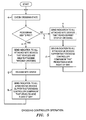
Figure 5 is a flow chart illustrating operation of the crossing controller shown inFigure 2 , -
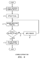
Figure 6 is a flow chart illustrating operation of the vehicle shown inFigure 1 , -
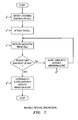
Figure 7 is a flow chart illustrating operation of the user terminal (User Equipment, UE) of the network shown inFigure 1 , -
Figure 8 is a diagram illustrating a network according to a second embodiment of the invention, -
Figure 9 is a diagram illustrating the crossing controller of the network shown inFigure 8 , -
Figure 10 is a diagram illustrating the machine type communication (MTC) device of the vehicle of the network shown inFigure 8 , -
Figure 11 is a diagram illustrating a network according to a further embodiment of the invention, and -
Figure 12 is a diagram illustrating the crossing controller of the network shown inFigure 11 . - The inventors realised that road and rail accidents and incidents are often caused by drivers of vehicles not obeying traffic signals deployed at the crossings, for example not stopping at red lights or deliberately driving around barriers that have been lowered.
- The inventors also realised that some pedestrian crossings use a tone to indicate to partially-sighted pedestrians that they may cross, but do not have a mechanism to indicate positively to such person that they are no longer allowed to cross, for example when a pedestrian crossing light is red.
- The inventors found a way to help reduce the number of these accidents and incidents at these crossings by including an automated system that reduces the chances of crossing signals being ignored or not noticed by drivers of vehicles.
- More specifically, when considering the known system involving traffic signals and barriers, the inventors realised that drivers of vehicles might not notice or deliberately ignore signals or barriers, for example swerving under a descending barrier, or not responding promptly to a warning stop light.
- The inventors realised that one way to introduce an automated system for deployment at crossings would be to utilise a wireless network that is local to a specific crossing.
- The inventors also realised that although the vast majority of vehicles have a driver in control, there is some interest in deploying driverless vehicles. They realised that if such vehicles were to ever to be allowed to use the conventional road network, appropriate automatic control of such vehicles would be needed when approaching pedestrian and rail crossings.
- As shown in
Figure 1 , aroad 2 has apedestrian crossing 4. Afemtocell base station 6 is provided at thecrossing 4. Thefemtocell base station 6 is connected to thetraffic lights system 8. Thefemtocell base station 6 includes avehicle crossing controller 10. -
Vehicles 12, one of which is shown inFigure 1 , each include a machine type communication, MTC,device 14 connected via abrake controller 16 to thebraking system 18. - In this example, pedestrians wishing to cross each carry a mobile user terminal. One
pedestrian 20 carrying onemobile user terminal 22 is shown inFigure 1 for simplicity. In this example, the pedestrian may be blind or partially-sighted. - As shown in
Figure 2 , thevehicle crossing controller 10 includes aconnection 24 to thetraffic lights system 8, theconnection 24 being to a trafficlights state detector 26 which is connected to a vehicle stop/release instructor circuit 28 and to a user terminalstop indication controller 29. The stop/release instructor circuit 28 and user terminalstop indication controller 29 are both connected via atransceiver 30 to anantenna 32. - As shown in
Figure 3 , theMTC device 14 in thevehicle 12 includes anantenna 34 connected to atransceiver circuit 36 which is connected to a stop/release instruction detector 38. Theoutput 40 of the stop/release instruction detector 38 is connected to thebrake controller 16. - As shown in
Figure 4 , theuser terminal 22 runs anapplication 23 which is a crossing controller companion application as will be explained below. - Operation of this example system will now be described first broadly then in more detail.
- When the
vehicle 12 approaches thecrossing 4, theMTC device 14 automatically attaches wirelessly to thefemtocell base station 6. Upon attaching, thevehicle crossing controller 10 provides theMTC device 14 with an indication of the current state of the crossing, for example whether thevehicle 12 has right of way (road traffic lights are green) or alternatively a pedestrian has right of way (road traffic lights are red or amber). - If the vehicle has right of way, one of the
MTC device 14 andfemtocell base station 6 releases the wireless attachment between the MTC device and femtocell base station, and the vehicle may proceed through the crossing. However, if it is determined that a pedestrian has right of way, theMTC device 14 receives an indication from thevehicle crossing controller 10 of thefemtocell base station 6. TheMTC device 14 then triggers thebrake controller 16 to apply thebrake system 18 so as to halt the vehicle before the crossing. Once any pedestrians have crossed safely, and the road traffic lights have turned green, thevehicle crossing controller 10 indicates to theMTC device 14 that the brakes can be released and the driver may proceed through the crossing. TheMTC device 14 then triggers thebrake controller 16 to release thebrakes 18. - It will be appreciated that in certain circumstances the MTC device acts to automatically stop the vehicle. This provides extra protection over known approaches that rely on the driver correctly obeying visual signals in the form of traffic lights as to whether or not to proceed.
- Operation is explained in some more detail as follows, referring to
Figures 5 to 7 . - As shown in
Figure 5 , the crossingcontroller 10 checks (step a) the state of the crossing and upon determining (step b) that the pedestrian light is not red, sends (step c) a stop instruction to all attached MTC devices and also sends (step d) a walk indication to all attached user terminals. - Later upon the crossing controller determining (step e) that pedestrian light being turned red ('don't walk') and so the road traffic light green, the crossing controller then sends (step f) a further indication to the MTC devices to control (step g) the
brake controller 16 to release thebrakes 18 so the vehicle may proceed through thecrossing 4. The crossing controller then sends (step h) a warning stop indication to all attached user terminals, namely of pedestrians, that the vehicles now have right of way. - Referring to
Figure 6 , at the same time as the vehicle traffic lights turn red, thevehicle 12 approaches thecrossing 4, so itsMTC device 14 detects (step a') and attaches wirelessly (step b') to thefemtocell base station 6. The stop instruction is received (step c') at theMTC device 14 from the crossingcontroller 10 indicating that the road traffic light is red and the pedestrian has right of way. - The
MTC device 14 immediately controls (step d') thebrake controller 16 to cause thebrakes 18 to be applied (step c'). In consequence the vehicle automatically comes to a halt before thecrossing 4. - After the pedestrian crosses, the pedestrian light is turned red and the road traffic light is turned green. The
MTC device 14 then receives (step f) a further indication from the crossingcontroller 10 to control (step g') thebrake controller 16 to release (step h') thebrakes 18 so the vehicle may proceed through thecrossing 4. - The partially-sighted
pedestrian 20 approaches thecrossing 4. The pedestrian has amobile user terminal 22 of a type that runs Applications. The terminal 22 runs the crossingcontroller companion application 23. - As shown in
Figure 7 , this Application causes the terminal 22 to detect (step a") and wirelessly attach (step b") to thefemtocell base station 6 and so thevehicle crossing controller 10. - The
application 23 receives (step c") wirelessly a stop indication from the crossingcontroller 10 because the pedestrian light is detected to be red, in other words, vehicles has right of way. In consequence the mobile terminal alerts (step d") the pedestrian, in this example by repeating a cycle of three periods of vibration, each period being of two seconds. - The pedestrian then reaches the
crossing 4 and presses the control button (not shown) to indicate that the pedestrian wishes to cross. - A short while later, the pedestrian light is green and the road traffic light is red. The crossing then emits a series of tones so the partially-sighted pedestrian is aware that they may cross. In addition the crossing
controller 10 of thefemtocell base station 6 indicated to theApplication 23 that the pedestrian may cross. The pedestrian is alerted (step e") via his user terminal of permission to cross, in this example, by a repeating cycle of periods of vibration of 1 second duration. - The 'don't walk' indication is particularly important as the partially-sighted
pedestrian 20 approaches thecrossing 4. - In this example, the crossing
controller application 23 on theuser terminal 22 also provides a indication to thepedestrian 20 of an unknown crossing state, in the event that theuser terminal 22 attaches to thefemtocell base station 6, but that connection is lost before the crossingcontroller 10 has indicated that the pedestrian may cross or the pedestrian may not cross. This indication is a default, being used when theuser terminal 22 has recently provided an indication that the pedestrian may cross or an indication that the pedestrian may not cross, but the connection with thefemtocell base station 6 is then lost. - It will be understood that the crossing
controller 10 in thefemtocell base station 6 aids the partially-sighted pedestrian by automatically providing an indication to hisuser terminal 22, for example a mobile phone, informing him when he may or may not cross at the crossing. In other words, thepedestrian 20 is informed via hisuser terminal 22 as to whether the pedestrian crossing lights are red (meaning stop, 'don't walk') or green (meaning walk). This is done by causing theuser terminal 22 to clearly indicate, for example by a predefined set of vibration periods, the current state of the crossing to the pedestrian. - As shown in
Figures 8 to 10 , another example is similar to the example described with reference toFigure 1 to 7 , except that there is no interaction with any pedestrian's user terminal, and the driver of the vehicle can manually override the automatic braking. - Specifically there is an
override button 40 in the vehicle 12' that a driver can press on approaching the crossing 4' to avoid the brake controller 16' from causing the brakes 18' to be applied automatically. - The MTC device 14' in the vehicle 12' detects the override in an
override detector 42 which causes a message to be sent by the MTC device 14' which is detected by the crossing controller 10' and indicates that automatic braking has been overridden. - Statistics are recorded in an
override log 44 of the crossing controller 10' about the overrides. Specifically, the identity of the MTC device 14' is recorded together with the date and time of the override. This information is then available for investigations into any incidents at the crossing 4'. - In another example (not shown) the femtocell base station including the crossing controller is deployed at a railway crossing, and road vehicles include MTC devices. As a vehicle approaches the crossing, its MTC device attaches wirelessly to the femtocell, and is then provided by the femtocell base station with an indication of the state of the crossing, namely whether or not a barrier against vehicle traffic has been deployed so the vehicle may not cross.
- If it is determined that the barrier is not deployed, the MTC device or femtocell base station releases the wireless link between them and the vehicle may cross as normal. However, if it is determined that the barrier is deployed, the crossing controller causes the vehicle to automatically brake and so halt before the crossing.
- Once the train has passed, the barrier is raised and that state of the crossing is determined by the crossing controller. The crossing controller then indicates to the MTC device that the vehicle's brakes may be released and the driver may drive the vehicle onwards through the crossing.
- Railway crossings are known to be deployed in rural or isolated areas in many countries, but which do not have associated traffic light systems.
- As shown in
Figure 11 , a railway crossing 46 is provided where aroad 48 crosses arailway 50. Afemtocell base station 52 is provided at thecrossing 46. Thefemtocell base station 6 includes avehicle crossing controller 54. As shown in more detail inFigure 12 , the crossingcontroller 54 includes acircuit 55 for identifying that the train is approaching, and a stop/gomessage generator 57. - As shown in
Figure 11 , the crossingcontroller 54 is connected by radio to arailway signalling network 56. - There is a
train 58 on therailway 50 and acar 60 on theroad 48. The car includes anMTC device 62. - In use, the
femtocell base station 52 recognises that thetrain 58 is approaching the crossing 46 so vehicles and/or pedestrians should be warned or halted. Specifically, the crossingcontroller 52 identifies incircuit 55 that a train is approaching and so thegenerator 57 generates a warning indication. Accordingly thefemtocell base station 52 issues a warning indication to MTC devices on cars near the crossing 46. In a similar embodiment (not shown), a halt instruction is sent by the femtocell base station to the MTC devices. - In this example, so pedestrians are also warned, the warning indication is also sent to a crossing controller companion application on the
user terminals 64 of the or eachnearby pedestrian 66 having his/heruser terminal 64 connected to the femtocell base station. - It will be understood that these provide an automated system at railway crossings to reduced or prevent accidents. Also, pedestrians in the area may well be encouraged by the provision of the automated system to use the designated crossing, rather than crossing the railway at apparently random points. They may do this as for example the femtocell base station would be recognised as providing wireless coverage to a pedestrian's user terminal so he or she can access the network, for example to check weather forecast, football scores, incoming email, etc.
- In a similar embodiment (not shown) to that shown in
Figure 11 , where traffic light signals are not provided, the femtocell base station provides a definite indication to attached MTC devices and user terminal as to whether or not a train is approaching the crossing. The femtocell base station's indication that a train is not approaching is a positive indication to vehicles and pedestrians that it is safe to cross the railway. In a similar embodiment, the indication includes information as to how far away the next train to approach is. This provides the vehicle driver or pedestrian with information as to how long they have to cross the railway before the femtocell base station will indicate/instruct vehicle drivers and pedestrians to stop at the crossing. - Another example system (not shown) is as described with reference to
Figures 1 to 7 above in which a vehicle is controlled, except that there is no interaction with a pedestrian's user terminal (if any). - The present invention may be embodied in other specific forms without departing from its essential characteristics. The described embodiments are to be considered in all respects only as illustrative and not restrictive. The scope of the invention is, therefore, indicated by the appended claims rather than by the foregoing description. All changes that come within the meaning and range of equivalency of the claims are to be embraced within their scope.
- A person skilled in the art would readily recognize that steps of various above-described methods can be performed by programmed computers. Some embodiments relate to program storage devices, e.g., digital data storage media, which are machine or computer readable and encode machine-executable or computer-executable programs of instructions, wherein said instructions perform some or all of the steps of said above-described methods. The program storage devices may be, e.g., digital memories, magnetic storage media such as a magnetic disks and magnetic tapes, bard drives, or optically readable digital data storage media. Some embodiments involve computers programmed to perform said steps of the above-described methods.
Claims (15)
- A small cell base station comprising a receiver, a message generator, and a transmitter;
the small cell base station being configured for use near a crossing between one of a railway, road and footpath and another of a railway, road and footpath, in which:the receiver is configured to receive information regarding which of at least one of a railway vehicle, road vehicle and pedestrian has right of way at the crossing;the message generator is configured to generate a message indicating which of said at least one of a railway vehicle, road vehicle and pedestrian has right of way;the transmitter is configured to transmit the message by wireless transmission towards at least one of said at least one of a railway vehicle, road vehicle and pedestrian, upon the said at least one of a railway vehicle, road vehicle and pedestrian entering the small cell radio coverage area. - A small cell base station according to claim 1, in which the small cell base station is for use at the crossing which is where a road crosses a footpath, the information comprises crossing traffic signal information, and the message comprises a warning that the pedestrian has right of way or an instruction for the road vehicle to stop.
- A small cell base station according to claim 1, in which the small cell base station is for use at the crossing which is where a road crosses a footpath, the information comprises crossing traffic signal information, and the message comprises a warning that the pedestrian does not have right of way.
- A small cell base station according to claim 1, in which the small cell base station is for use at the crossing which is where a railway crosses at least one of a road and a footpath, and the message includes information from a railway signalling network.
- A small cell base station according to claim 4, in which the message includes information as to the time remaining until the next train approaches the crossing.
- A crossing comprising a small cell base station according to any preceding claim.
- A method of using a small cell base station near a crossing between one of a railway, road and footpath and another of a railway, road or footpath, the method comprising:receiving information regarding which of at least one of a railway vehicle, road vehicle and pedestrian has right of way at the crossing,generating a message indicating which of said at least one of a railway vehicle, road vehicle and pedestrian has right of way,transmitting the message by wireless transmission towards at least one of said at least one of a railway vehicle, road vehicle and pedestrian, upon the said at least one of a railway vehicle, road vehicle and pedestrian entering the small cell radio coverage area,the message being received and decoded by at least one terminal within the small cell area for use in guiding or controlling traffic.
- A method according to claim 7, in which the at least one terminal comprises a machine type communication, MTC, device which is mounted in the road vehicle, the vehicle having brakes which are selectably automatically applied dependent upon the received and decoded message indicating that a pedestrian or an approaching railway vehicle has right of way,
- A method according to claim 8, in which a driver of the road vehicle selectably enables or disables the automatic braking.
- A method according to any of claims 7 to 9, in which the at least one terminal comprises a user terminal carried by the pedestrian, the user terminal being configured to provide alerts to the pedestrian as to whether or not it is safe to now cross.
- A. vehicle braking circuit comprising a machine type communication, MTC, device, a detector, a brake controller and a brake, the MTC device being configured to receive over air a wireless signal indicating that the vehicle should stop,
the detector being configured to detect the indication to stop and to inform a brake controller of the indication,
the brake controller being configured to apply the brake automatically dependent upon being informed of the indication. - A vehicle braking circuit according to claim 11, including a driver input which enables temporary disablement by the driver of automatic braking.
- A vehicle braking circuit according to claim 12, in which the MTC device is configured to transmit a reply towards the small cell base station indicating that the disablement of automatic braking by driver input has been made.
- A vehicle comprising a vehicle braking circuit according to any of claims 11 to 13.
- A computer program product operable when executed on a computer to perform the method of any of claims 7 to 10.
Priority Applications (1)
| Application Number | Priority Date | Filing Date | Title |
|---|---|---|---|
| EP14290290.7A EP3001706A1 (en) | 2014-09-26 | 2014-09-26 | A small cell base station, a vehicle braking circuit, and method of using a small cell base station near a crossing |
Applications Claiming Priority (1)
| Application Number | Priority Date | Filing Date | Title |
|---|---|---|---|
| EP14290290.7A EP3001706A1 (en) | 2014-09-26 | 2014-09-26 | A small cell base station, a vehicle braking circuit, and method of using a small cell base station near a crossing |
Publications (1)
| Publication Number | Publication Date |
|---|---|
| EP3001706A1 true EP3001706A1 (en) | 2016-03-30 |
Family
ID=51752060
Family Applications (1)
| Application Number | Title | Priority Date | Filing Date |
|---|---|---|---|
| EP14290290.7A Withdrawn EP3001706A1 (en) | 2014-09-26 | 2014-09-26 | A small cell base station, a vehicle braking circuit, and method of using a small cell base station near a crossing |
Country Status (1)
| Country | Link |
|---|---|
| EP (1) | EP3001706A1 (en) |
Cited By (2)
| Publication number | Priority date | Publication date | Assignee | Title |
|---|---|---|---|---|
| CN108093464A (en) * | 2016-11-23 | 2018-05-29 | 普天信息技术有限公司 | Resource allocation method and device |
| CN109327854A (en) * | 2018-11-15 | 2019-02-12 | 中国联合网络通信集团有限公司 | Track user identification method and device |
Citations (1)
| Publication number | Priority date | Publication date | Assignee | Title |
|---|---|---|---|---|
| WO2014011887A1 (en) * | 2012-07-11 | 2014-01-16 | Carnegie Mellon University | A railroad interlocking system with distributed control |
-
2014
- 2014-09-26 EP EP14290290.7A patent/EP3001706A1/en not_active Withdrawn
Patent Citations (1)
| Publication number | Priority date | Publication date | Assignee | Title |
|---|---|---|---|---|
| WO2014011887A1 (en) * | 2012-07-11 | 2014-01-16 | Carnegie Mellon University | A railroad interlocking system with distributed control |
Non-Patent Citations (1)
| Title |
|---|
| ANDRÉ NIEUWLAND: "Vehicle to infrastructure communication with today's telecommunication systems", 7 May 2012 (2012-05-07), XP055185272, Retrieved from the Internet <URL:http://www.ftm.mw.tum.de/uploads/media/30_Nieuwland.pdf> [retrieved on 20150422] * |
Cited By (2)
| Publication number | Priority date | Publication date | Assignee | Title |
|---|---|---|---|---|
| CN108093464A (en) * | 2016-11-23 | 2018-05-29 | 普天信息技术有限公司 | Resource allocation method and device |
| CN109327854A (en) * | 2018-11-15 | 2019-02-12 | 中国联合网络通信集团有限公司 | Track user identification method and device |
Similar Documents
| Publication | Publication Date | Title |
|---|---|---|
| CN103236171B (en) | Traffic early-warning method, information transmitter, information receiver and traffic early-warning system | |
| CN207852107U (en) | Road surface monitoring system based on V2X and V2X roadside devices | |
| US20190172342A1 (en) | Smart crosswalk safety system for pedestrian | |
| US20150116133A1 (en) | Emergency vehicle alert system and method | |
| US20150254978A1 (en) | Emergency vehicle alert system and method | |
| KR101817529B1 (en) | Wireless transceivers for communicating work conditions to prevent railway accident | |
| CN206984023U (en) | Railway operation personnel safety guard's system | |
| CN110533902A (en) | Smart city emergency rescue channel system and method | |
| EP2617623A2 (en) | Rail crossing protection system | |
| US20090176457A1 (en) | Apparatus and method for communicating with moving receivers | |
| CN113393682A (en) | Wisdom zebra crossing system based on car networking | |
| EP3001706A1 (en) | A small cell base station, a vehicle braking circuit, and method of using a small cell base station near a crossing | |
| CN107848549B (en) | System and method for personnel evacuation of rail vehicles | |
| WO2020166663A1 (en) | Traffic communication system, base station, vehicle, mobile station and message transmission method | |
| EP2521110B1 (en) | A small cell base station, a method of controlling movement of a machine-type-communication (MTC) unit, and a braking system for a vehicle | |
| JP6292222B2 (en) | Communication system and distribution information determination device | |
| CN105139691B (en) | A kind of traffic prewarning method, apparatus and system | |
| CN102693630A (en) | Hand-held monitoring equipment, method and system for pedestrian violation behaviour based on mobile communication | |
| JP2001223821A (en) | Emergency call device and emergency call system | |
| JP7237634B2 (en) | Traffic communication systems, base stations and vehicles | |
| JP2001204109A (en) | Automatic train stop device | |
| KR102457278B1 (en) | Notification system and service method for pedestrian crossing signals for the visually impaired | |
| CN215643096U (en) | Highway vehicle-mounted terminal communication system | |
| RU2565159C2 (en) | System for protecting railway crossings | |
| JP2021095123A (en) | State information processing device and state information processing method |
Legal Events
| Date | Code | Title | Description |
|---|---|---|---|
| PUAI | Public reference made under article 153(3) epc to a published international application that has entered the european phase |
Free format text: ORIGINAL CODE: 0009012 |
|
| AK | Designated contracting states |
Kind code of ref document: A1 Designated state(s): AL AT BE BG CH CY CZ DE DK EE ES FI FR GB GR HR HU IE IS IT LI LT LU LV MC MK MT NL NO PL PT RO RS SE SI SK SM TR |
|
| AX | Request for extension of the european patent |
Extension state: BA ME |
|
| 17P | Request for examination filed |
Effective date: 20161005 |
|
| RBV | Designated contracting states (corrected) |
Designated state(s): AL AT BE BG CH CY CZ DE DK EE ES FI FR GB GR HR HU IE IS IT LI LT LU LV MC MK MT NL NO PL PT RO RS SE SI SK SM TR |
|
| 17Q | First examination report despatched |
Effective date: 20171124 |
|
| RAP1 | Party data changed (applicant data changed or rights of an application transferred) |
Owner name: ALCATEL LUCENT |
|
| STAA | Information on the status of an ep patent application or granted ep patent |
Free format text: STATUS: THE APPLICATION IS DEEMED TO BE WITHDRAWN |
|
| 18D | Application deemed to be withdrawn |
Effective date: 20190430 |