EP3001128B1 - Natural gas liquefaction process - Google Patents
Natural gas liquefaction process Download PDFInfo
- Publication number
- EP3001128B1 EP3001128B1 EP14800817.0A EP14800817A EP3001128B1 EP 3001128 B1 EP3001128 B1 EP 3001128B1 EP 14800817 A EP14800817 A EP 14800817A EP 3001128 B1 EP3001128 B1 EP 3001128B1
- Authority
- EP
- European Patent Office
- Prior art keywords
- stream
- heat exchange
- exchange part
- natural gas
- conduit
- Prior art date
- Legal status (The legal status is an assumption and is not a legal conclusion. Google has not performed a legal analysis and makes no representation as to the accuracy of the status listed.)
- Active
Links
Images


Classifications
-
- F—MECHANICAL ENGINEERING; LIGHTING; HEATING; WEAPONS; BLASTING
- F25—REFRIGERATION OR COOLING; COMBINED HEATING AND REFRIGERATION SYSTEMS; HEAT PUMP SYSTEMS; MANUFACTURE OR STORAGE OF ICE; LIQUEFACTION SOLIDIFICATION OF GASES
- F25J—LIQUEFACTION, SOLIDIFICATION OR SEPARATION OF GASES OR GASEOUS OR LIQUEFIED GASEOUS MIXTURES BY PRESSURE AND COLD TREATMENT OR BY BRINGING THEM INTO THE SUPERCRITICAL STATE
- F25J1/00—Processes or apparatus for liquefying or solidifying gases or gaseous mixtures
- F25J1/02—Processes or apparatus for liquefying or solidifying gases or gaseous mixtures requiring the use of refrigeration, e.g. of helium or hydrogen ; Details and kind of the refrigeration system used; Integration with other units or processes; Controlling aspects of the process
- F25J1/0211—Processes or apparatus for liquefying or solidifying gases or gaseous mixtures requiring the use of refrigeration, e.g. of helium or hydrogen ; Details and kind of the refrigeration system used; Integration with other units or processes; Controlling aspects of the process using a multi-component refrigerant [MCR] fluid in a closed vapor compression cycle
- F25J1/0212—Processes or apparatus for liquefying or solidifying gases or gaseous mixtures requiring the use of refrigeration, e.g. of helium or hydrogen ; Details and kind of the refrigeration system used; Integration with other units or processes; Controlling aspects of the process using a multi-component refrigerant [MCR] fluid in a closed vapor compression cycle as a single flow MCR cycle
-
- F—MECHANICAL ENGINEERING; LIGHTING; HEATING; WEAPONS; BLASTING
- F25—REFRIGERATION OR COOLING; COMBINED HEATING AND REFRIGERATION SYSTEMS; HEAT PUMP SYSTEMS; MANUFACTURE OR STORAGE OF ICE; LIQUEFACTION SOLIDIFICATION OF GASES
- F25B—REFRIGERATION MACHINES, PLANTS OR SYSTEMS; COMBINED HEATING AND REFRIGERATION SYSTEMS; HEAT PUMP SYSTEMS
- F25B43/00—Arrangements for separating or purifying gases or liquids; Arrangements for vaporising the residuum of liquid refrigerant, e.g. by heat
-
- F—MECHANICAL ENGINEERING; LIGHTING; HEATING; WEAPONS; BLASTING
- F25—REFRIGERATION OR COOLING; COMBINED HEATING AND REFRIGERATION SYSTEMS; HEAT PUMP SYSTEMS; MANUFACTURE OR STORAGE OF ICE; LIQUEFACTION SOLIDIFICATION OF GASES
- F25B—REFRIGERATION MACHINES, PLANTS OR SYSTEMS; COMBINED HEATING AND REFRIGERATION SYSTEMS; HEAT PUMP SYSTEMS
- F25B5/00—Compression machines, plants or systems, with several evaporator circuits, e.g. for varying refrigerating capacity
- F25B5/04—Compression machines, plants or systems, with several evaporator circuits, e.g. for varying refrigerating capacity arranged in series
-
- F—MECHANICAL ENGINEERING; LIGHTING; HEATING; WEAPONS; BLASTING
- F25—REFRIGERATION OR COOLING; COMBINED HEATING AND REFRIGERATION SYSTEMS; HEAT PUMP SYSTEMS; MANUFACTURE OR STORAGE OF ICE; LIQUEFACTION SOLIDIFICATION OF GASES
- F25J—LIQUEFACTION, SOLIDIFICATION OR SEPARATION OF GASES OR GASEOUS OR LIQUEFIED GASEOUS MIXTURES BY PRESSURE AND COLD TREATMENT OR BY BRINGING THEM INTO THE SUPERCRITICAL STATE
- F25J1/00—Processes or apparatus for liquefying or solidifying gases or gaseous mixtures
- F25J1/0002—Processes or apparatus for liquefying or solidifying gases or gaseous mixtures characterised by the fluid to be liquefied
- F25J1/0022—Hydrocarbons, e.g. natural gas
-
- F—MECHANICAL ENGINEERING; LIGHTING; HEATING; WEAPONS; BLASTING
- F25—REFRIGERATION OR COOLING; COMBINED HEATING AND REFRIGERATION SYSTEMS; HEAT PUMP SYSTEMS; MANUFACTURE OR STORAGE OF ICE; LIQUEFACTION SOLIDIFICATION OF GASES
- F25J—LIQUEFACTION, SOLIDIFICATION OR SEPARATION OF GASES OR GASEOUS OR LIQUEFIED GASEOUS MIXTURES BY PRESSURE AND COLD TREATMENT OR BY BRINGING THEM INTO THE SUPERCRITICAL STATE
- F25J1/00—Processes or apparatus for liquefying or solidifying gases or gaseous mixtures
- F25J1/003—Processes or apparatus for liquefying or solidifying gases or gaseous mixtures characterised by the kind of cold generation within the liquefaction unit for compensating heat leaks and liquid production
- F25J1/0047—Processes or apparatus for liquefying or solidifying gases or gaseous mixtures characterised by the kind of cold generation within the liquefaction unit for compensating heat leaks and liquid production using an "external" refrigerant stream in a closed vapor compression cycle
- F25J1/0052—Processes or apparatus for liquefying or solidifying gases or gaseous mixtures characterised by the kind of cold generation within the liquefaction unit for compensating heat leaks and liquid production using an "external" refrigerant stream in a closed vapor compression cycle by vaporising a liquid refrigerant stream
- F25J1/0055—Processes or apparatus for liquefying or solidifying gases or gaseous mixtures characterised by the kind of cold generation within the liquefaction unit for compensating heat leaks and liquid production using an "external" refrigerant stream in a closed vapor compression cycle by vaporising a liquid refrigerant stream originating from an incorporated cascade
-
- F—MECHANICAL ENGINEERING; LIGHTING; HEATING; WEAPONS; BLASTING
- F25—REFRIGERATION OR COOLING; COMBINED HEATING AND REFRIGERATION SYSTEMS; HEAT PUMP SYSTEMS; MANUFACTURE OR STORAGE OF ICE; LIQUEFACTION SOLIDIFICATION OF GASES
- F25J—LIQUEFACTION, SOLIDIFICATION OR SEPARATION OF GASES OR GASEOUS OR LIQUEFIED GASEOUS MIXTURES BY PRESSURE AND COLD TREATMENT OR BY BRINGING THEM INTO THE SUPERCRITICAL STATE
- F25J1/00—Processes or apparatus for liquefying or solidifying gases or gaseous mixtures
- F25J1/02—Processes or apparatus for liquefying or solidifying gases or gaseous mixtures requiring the use of refrigeration, e.g. of helium or hydrogen ; Details and kind of the refrigeration system used; Integration with other units or processes; Controlling aspects of the process
- F25J1/0243—Start-up or control of the process; Details of the apparatus used; Details of the refrigerant compression system used
- F25J1/0257—Construction and layout of liquefaction equipments, e.g. valves, machines
- F25J1/0262—Details of the cold heat exchange system
- F25J1/0264—Arrangement of heat exchanger cores in parallel with different functions, e.g. different cooling streams
- F25J1/0265—Arrangement of heat exchanger cores in parallel with different functions, e.g. different cooling streams comprising cores associated exclusively with the cooling of a refrigerant stream, e.g. for auto-refrigeration or economizer
-
- F—MECHANICAL ENGINEERING; LIGHTING; HEATING; WEAPONS; BLASTING
- F25—REFRIGERATION OR COOLING; COMBINED HEATING AND REFRIGERATION SYSTEMS; HEAT PUMP SYSTEMS; MANUFACTURE OR STORAGE OF ICE; LIQUEFACTION SOLIDIFICATION OF GASES
- F25J—LIQUEFACTION, SOLIDIFICATION OR SEPARATION OF GASES OR GASEOUS OR LIQUEFIED GASEOUS MIXTURES BY PRESSURE AND COLD TREATMENT OR BY BRINGING THEM INTO THE SUPERCRITICAL STATE
- F25J1/00—Processes or apparatus for liquefying or solidifying gases or gaseous mixtures
- F25J1/02—Processes or apparatus for liquefying or solidifying gases or gaseous mixtures requiring the use of refrigeration, e.g. of helium or hydrogen ; Details and kind of the refrigeration system used; Integration with other units or processes; Controlling aspects of the process
- F25J1/0243—Start-up or control of the process; Details of the apparatus used; Details of the refrigerant compression system used
- F25J1/0279—Compression of refrigerant or internal recycle fluid, e.g. kind of compressor, accumulator, suction drum etc.
- F25J1/0291—Refrigerant compression by combined gas compression and liquid pumping
-
- F—MECHANICAL ENGINEERING; LIGHTING; HEATING; WEAPONS; BLASTING
- F25—REFRIGERATION OR COOLING; COMBINED HEATING AND REFRIGERATION SYSTEMS; HEAT PUMP SYSTEMS; MANUFACTURE OR STORAGE OF ICE; LIQUEFACTION SOLIDIFICATION OF GASES
- F25J—LIQUEFACTION, SOLIDIFICATION OR SEPARATION OF GASES OR GASEOUS OR LIQUEFIED GASEOUS MIXTURES BY PRESSURE AND COLD TREATMENT OR BY BRINGING THEM INTO THE SUPERCRITICAL STATE
- F25J1/00—Processes or apparatus for liquefying or solidifying gases or gaseous mixtures
- F25J1/02—Processes or apparatus for liquefying or solidifying gases or gaseous mixtures requiring the use of refrigeration, e.g. of helium or hydrogen ; Details and kind of the refrigeration system used; Integration with other units or processes; Controlling aspects of the process
- F25J1/0243—Start-up or control of the process; Details of the apparatus used; Details of the refrigerant compression system used
- F25J1/0279—Compression of refrigerant or internal recycle fluid, e.g. kind of compressor, accumulator, suction drum etc.
- F25J1/0294—Multiple compressor casings/strings in parallel, e.g. split arrangement
-
- F—MECHANICAL ENGINEERING; LIGHTING; HEATING; WEAPONS; BLASTING
- F25—REFRIGERATION OR COOLING; COMBINED HEATING AND REFRIGERATION SYSTEMS; HEAT PUMP SYSTEMS; MANUFACTURE OR STORAGE OF ICE; LIQUEFACTION SOLIDIFICATION OF GASES
- F25B—REFRIGERATION MACHINES, PLANTS OR SYSTEMS; COMBINED HEATING AND REFRIGERATION SYSTEMS; HEAT PUMP SYSTEMS
- F25B41/00—Fluid-circulation arrangements
- F25B41/30—Expansion means; Dispositions thereof
- F25B41/39—Dispositions with two or more expansion means arranged in series, i.e. multi-stage expansion, on a refrigerant line leading to the same evaporator
-
- F—MECHANICAL ENGINEERING; LIGHTING; HEATING; WEAPONS; BLASTING
- F25—REFRIGERATION OR COOLING; COMBINED HEATING AND REFRIGERATION SYSTEMS; HEAT PUMP SYSTEMS; MANUFACTURE OR STORAGE OF ICE; LIQUEFACTION SOLIDIFICATION OF GASES
- F25J—LIQUEFACTION, SOLIDIFICATION OR SEPARATION OF GASES OR GASEOUS OR LIQUEFIED GASEOUS MIXTURES BY PRESSURE AND COLD TREATMENT OR BY BRINGING THEM INTO THE SUPERCRITICAL STATE
- F25J2210/00—Processes characterised by the type or other details of the feed stream
- F25J2210/06—Splitting of the feed stream, e.g. for treating or cooling in different ways
Definitions
- the present invention relates to a natural gas liquefaction process, and more particularly, to a natural gas liquefaction process which is capable of being simplified in structure and being easily operated as well as having excellent efficiency.
- thermodynamic process of liquefying natural gas to produce liquefied natural gas has been developed since 1970s in order to satisfy various assignments including demands for higher efficiency and larger capacity.
- LNG liquefied natural gas
- various attempts to liquefy natural gas by using different refrigerants or different cycles have been continuously conducted up to now.
- the number of liquefaction processes that are practically used is very small.
- a 'propane pre-cooled mixed refrigerant process (or a C3/MR process)'.
- natural gas NG
- JT Joule-Thomson
- propane cycle propane refrigerant
- MR mixed refrigerant
- multi-component refrigerant a mixed refrigerant
- Another one of the liquefaction processes that are being operated is a cascade process by Conoco Phillips Company.
- the liquefaction process by Conoco Phillips Company consists of three Joule-Thomson cycles using methane C1, ethylene C2, and propane C3.
- the cascade process uses only the refrigeration cycle using the single refrigerant, the liquefaction process is simplified in operation and improved in reliability.
- an individual equipment e.g., a heat exchanger
- the liquefaction process needs to be increased in scale.
- Another one of the liquefaction processes that are being operated is a 'single mixed refrigerant process (or SMR process)'.
- SMR process the natural gas is liquefied through a single closed-loop refrigeration cycle using the mixed refrigerant.
- the above-mentioned SMR process has an advantage that the liquefaction process is simplified in structure.
- the SMR process has a disadvantage in that the liquefaction process has low efficiency.
- US 6,308,531 discloses a process according to the preamble of claim 1 for liquefied natural gas production. This process involves the compression of a gas to a high pressure, and then liquefying this gas against a cooling source. As a consequence, the resulting liquid expands to a low pressure. Since the resulting liquid then vaporizes, it provides refrigeration. This process does not involve two refrigerants that are compressed in parallel prior to being mixed.
- an objective of the present invention is to provide a natural gas liquefaction process which is capable of being simplified in structure and being easily operated as well as having excellent efficiency.
- a natural gas liquefaction process according to the present invention relates to a natural gas liquefaction process according to claim 1.
- the liquefaction process since the single closed-loop refrigeration cycle using the mixed refrigerant is used, the liquefaction process may be simplified in structure and easily operated. In addition, since a single stream is separated into two streams, and then, each of the two streams cools the natural gas, the liquefaction process may have the excellent efficiency.
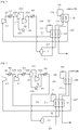
- FIG. 1 is a flowchart illustrating a natural gas liquefaction process according to Example Process 1 of the present description.
- a liquefaction process according to Example Process 1 of the present description may be applied to a process in which a single closed-loop refrigeration cycle is used to cool natural gas up to a liquefaction temperature, thereby producing liquefied natural gas (LNG).
- LNG liquefied natural gas
- the liquefaction process may be applied to a natural gas liquefaction process in which natural gas is primarily cooled in a first heat exchange part and then secondarily cooled in a second heat exchange part distinguished from the first heat exchange part by using a single closed-loop refrigeration cycle using a mixed refrigerant or multi-component refrigerant.
- the liquefaction process according to the current example may further include a refrigeration cycle for additionally cooling the mixed refrigerant or the natural gas.
- a mixed refrigerant (a main stream that will be described below) is partially condensed (a condensation step). That is, the mixed refrigerant is partially condensed through a series of compression processes.
- the mixed refrigerant includes a liquid phase refrigerant and a gas phase refrigerant.
- the mixed refrigerant is introduced into a separation unit 111 and separated into a first stream having a liquid phase and a second stream having a gas phase (a first separation step).
- the separation unit 111 may be a normal vapor-liquid separator. This may be equally applied to a different separation unit that will be described below.
- the first stream is introduced into a first heat exchange part 121 through a conduit 211 (a first introduction step). Then, the first stream is discharged from the first heat exchange part 121 and then introduced into an expansion unit 131 and expanded (a first expansion step). Thus, the first stream decreases in temperature.
- the expansion unit may include a Joule-Thomson (J-T) valve.
- J-T Joule-Thomson
- the expansion unit may include a normal expansion valve.
- the expansion unit may include an expander. This may be equally applied to a different expansion unit that will be described below.
- the J-T valve may reduce all of a pressure and a temperature of the stream through a J-T effect.
- the first stream decreases in temperature due to the expansion and is introduced again into the first heat exchange part 121 through a conduit 212 to cool the natural gas (NG) in the first heat exchange part 121 (a first cooling step).
- the first stream introduced into the first heat exchange part 121 through the conduit 212 cools the natural gas together with the first stream introduced into the first heat exchange part 121 through the conduit 211 and the second stream introduced into the first heat exchange part 121 through a conduit 221.
- the natural gas may be pre-cooled through the above-described cooling.
- the first stream performs the cooling in the first heat exchange part 121 and then is recovered from the first heat exchange part 121 (a first recovery step).
- the first stream is recovered from the first heat exchange part 121 and then transferred for the condensation step through the conduit 213.
- the second stream is introduced into the first heat exchange part 121 through the conduit 221 (a second introduction step).
- the second stream is cooled by the first stream introduced into the first heat exchange part 121 through the conduit 212.
- the second stream is introduced into a second heat exchange part 122 through a conduit 222 (a third introduction step).
- the second stream is discharged from the second heat exchange part 122 and then introduced into the expansion unit 132 and expanded (a second expansion step).
- the second stream decreases in temperature through the above-described expansion.
- the second stream decreases in temperature due to the expansion and is introduced again into the second heat exchange part 122 through a conduit 223 to cool the natural gas in the second heat exchange part 122 (a second cooling step).
- the natural gas may be liquefied through the above-described cooling.
- the second stream performs the cooling in the second heat exchange part 122 and then is recovered from the second heat exchange part 122 (a second recovery step).
- the second stream is recovered from the second heat exchange part 122 and then transferred for the condensation step through a conduit 224.
- the first heat exchange part 121 includes a spiral wound heat exchanger (SWHE)-type heat exchanger.
- SWHE spiral wound heat exchanger
- PFHE plate fin heat exchanger
- SWHE spiral wound heat exchanger
- a stream for cooling a different stream may be provided in plurality, and a stream cooled by a different stream may be provided in plurality.
- a stream for cooling a different stream is provided in one, or a stream cooled by a different stream is provided in one.
- the liquefaction process using the SWHE-type heat exchanger may be different from that using the PFHE-type heat exchanger. That is, the liquefaction process based on the PFHE-type heat exchanger may not be applied to that using the SWHE-type heat exchanger as it is.
- a single stream (a main stream that will be described below) is separated into two streams (a first stream and a second stream), and then the two streams are respectively used for cooling the natural gas in the first and second heat exchange parts 121 and 122.
- the first heat exchange part 121 may be provided as one SWHE-type heat exchanger, and the second heat exchange part 122 may be provided as the other SWHE-type heat exchanger.
- the SWHE-type heat exchanger is advantageous when a liquefaction system has large capacity.
- the SWHE-type heat exchanger is advantageous for maintaining and repairing the liquefaction system.
- the natural gas is liquefied by using the single closed-loop refrigeration cycle.
- the liquefaction process according to the current embodiment has advantages in that the liquefaction process is simplified in structure and easily operated.
- a single stream is separated into two streams, and then, each of the two streams cools the natural gas.
- the liquefaction process according to the current example includes a single refrigeration cycle, the liquefaction process may have an effect as if the natural gas is cooled through two refrigeration cycles. As a result, the liquefaction process may have excellent efficiency.
- the condensation step may be described in more detail as follows.
- the second stream is recovered from the second heat exchange part 122 and then introduced into a compression unit 141 through a conduit 224 and compressed (a first compression step).
- the compression unit 141 may be a normal compressor.
- the compression unit 141 may be a multi-stage compressor. This may be equally applied to a different compression unit that will be described below.
- the second stream is introduced into a cooling unit 151 through a conduit 231 and cooled.
- the cooling unit 151 may be a water cooling type or air cooling type cooler. This may be equally applied to a different cooling unit that will be described below.
- the cooling unit 151 may be selectively provided. That is, the cooling unit 151 may be provided when it is necessary to cool the compressed stream. This may be equally applied to a different cooling unit.
- the second stream is mixed with the first stream after the above-described cooling. That is, the first stream is recovered from the first heat exchange part 121 and then mixed with the second stream (a first mixing step).
- the above-described mixing may be achieved by connecting on conduit 213 to the other conduit 232.
- a separate constituent for the mixing may be provided.
- the main stream may be formed through the mixing. That is, the main stream may be a stream in which the first stream and the second stream are mixed with each other.
- the main stream is compressed by a compression unit 142 (a second compression step). Then, the main stream is introduced into a cooling unit 152 through a conduit 233 and cooled.
- the main stream is partially condensed through the series of processes and introduced into a separation unit 111 through a conduit 234.
- the mixing may be a relative concept. That is, the first and second streams may be mixed with each other, or the second stream may be mixed with the first stream according to the structure of the conduit. Also, the first and second streams may be independently introduced into the compression unit 142 and then mixed with each other in the compression unit 142. Also, the above-described conduits may be different from each other or the same according to the reference numerals. That is, for convenience of description, two reference numerals may be given to only one conduit. On the other hand, for convenience of description, only one reference numeral may be given to two conduits.
- FIG. 2 is a flowchart illustrating a first modified example of the natural gas liquefaction process of FIG. 1 .
- the condensation process basically further includes a third compression step and a fourth compression step.
- a main stream in the liquefaction process according to the modified example is cooled by a cooling unit 152 and then introduced into a compression unit 143 through a conduit 2341 and compressed (a third compression step). Then, the main stream is introduced into a cooling unit 153 through a conduit 2342 and cooled.
- the main stream is introduced into a separation unit 112 through a conduit 2343 and then separated into a third stream having a liquid phase and a fourth stream having a gas phase (a second separation step).
- the third stream is mixed with the main stream within the conduit 2341 through a conduit 2344 (a second mixing step).
- the third stream is expanded by an expansion unit and then mixed with the main stream.
- the third stream is introduced into the compression unit 143 together with the main stream.
- the fourth stream is introduced into a compression unit 144 through a conduit 2345 and compressed (a fourth compression step).
- the fourth stream is introduced into a cooling unit 154 through a conduit 2346 and cooled.
- the fourth stream is partially condensed through the series of processes and introduced into a separation unit 111 through a conduit 2347.
- the compression unit receives a gas refrigerant.
- a liquid refrigerant may be generated.
- the separation unit 112 is used as described in the modified example, only the gas refrigerant may be supplied into the compression unit.
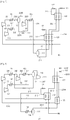
- FIG. 3 is a flowchart illustrating a second modified example of the natural gas liquefaction process of FIG. 1 .
- the second stream is recovered from the second heat exchange part 122 and then introduced into a compression unit 141 through a conduit 224 and compressed (a first compression step). Then, the second stream is introduced into a cooling unit 151 through a conduit 231 and cooled.
- the second stream is mixed with the first stream after the cooling. That is, the first stream is recovered from the first heat exchange part 121 and then mixed with the second stream (a first mixing step).
- the main stream may be formed through the mixing.
- the main stream is introduced into a separation unit 112 through a conduit 2321 and then separated into a third stream having a liquid phase and a fourth stream having a gas phase (a second separation step).
- the fourth stream is introduced into a compression unit 142 through a conduit 2322 and compressed (a second compression step).
- the fourth stream is mixed with the third stream (a second mixing step).
- the third stream may be forcibly transferred into a conduit 2324 by a pump 161.
- the third stream and the fourth stream are introduced into a cooling unit 152 through a conduit 2324 and cooled.
- the main stream is partially condensed through the series of processes and introduced into a separation unit 111 through a conduit 234.
- the liquid refrigerant which may be generated while the refrigerant is compressed may be increased in pressure by using a refrigerant pump because the liquid refrigerant is not increased in pressure by using a refrigerant compressor.
- FIG. 4 is a flowchart illustrating a first modified example of the natural gas liquefaction process of FIG. 1 .
- a compression unit 1411 may be further provided.
- the main stream is introduced into the compression unit 1411 through a conduit 1231 and compressed.
- the main stream is introduced into a cooling unit 1511 through a conduit 1232 and cooled.
- the main stream is introduced into a separation unit 112 through a conduit 1233.
- the liquid refrigerant which may be generated while the refrigerant is additionally compressed may be increased in pressure by using a refrigerant pump, like the additional compression stage as described in the modified example, because the liquid refrigerant is not increased in pressure by using a refrigerant compressor.
- FIG. 5 is a flowchart illustrating a first modified example of the natural gas liquefaction process of FIG. 1 .
- the second stream is recovered from the second heat exchange part 122 and then introduced into a compression unit 141 through a conduit 224 and compressed (a first compression step). Then, the second stream is introduced into a cooling unit 151 through a conduit 231 and cooled.
- the first stream is recovered from the first heat exchange part 121 and then introduced into a compression unit 142 through a conduit 213 and compressed (a second compression step). Then, the first stream is introduced into a cooling unit 152 through a conduit 291 and cooled.
- the first stream is mixed with the second stream within the conduit 292 through a conduit 232 (a first mixing step).
- the main stream may be formed through the mixing. That is, the main stream may be a stream in which the first stream and the second stream are mixed with each other.
- the main stream is compressed by the compression unit 143 (a third compression step).
- the main stream is introduced into a cooling unit 153 through a conduit 233 and cooled.
- the main stream is partially condensed through the series of processes and introduced into a separation unit 111 through a conduit 234.
- the main stream is separated into the first and second streams by the separation unit 111, and then, the first and second streams are not mixed with each other until the first and second streams are compressed by the compression units 141 and 142.
- conditions different from each other for example, pressure conditions
- the liquefaction process according to the modified example may be very advantageous for optimizing the liquefaction process.
- FIG. 6 is a flowchart illustrating a fifth modified example of the natural gas liquefaction process of FIG. 1 .
- the second stream is recovered from the second heat exchange part 122 and then introduced into a compression unit 141 through a conduit 224 and compressed (a first compression step).
- the second stream is introduced into a cooling unit 151 through a conduit 241 and cooled.
- the first stream is recovered from the first heat exchange part 121 and then introduced into a compression unit 142 through a conduit 213 and compressed (a second compression step).
- the first stream is introduced into a cooling unit 152 through a conduit 251 and cooled.
- the second stream is introduced into a compression unit 143 through a conduit 242 and compressed (a third compression step).
- the second stream is introduced into a cooling unit 153 through a conduit 243 and cooled.
- the second stream is mixed with the first stream. That is, the first stream is mixed with the second stream within the conduit 252 through a conduit 244 (a first mixing step).
- the main stream may be formed through the mixing.
- the main stream is introduced into a separation unit 112 and then separated into a third stream having a liquid phase and a fourth stream having a gas phase (a second separation step).
- the third stream is mixed with the second stream within the conduit 245 through a conduit 242 (a second mixing step).
- the third stream is expanded by an expansion unit and then mixed with the second stream.
- the third stream is introduced into the compression unit 143 together with the second stream.
- the fourth stream is introduced into a compression unit 144 through a conduit 246 and compressed (a fourth compression step). Then, the fourth stream is introduced into a cooling unit 154 through a conduit 247 and cooled. The fourth stream is partially condensed through the series of processes and introduced into a separation unit 111 through a conduit 248.
- the liquefaction process according to the modified example may have the same characteristics as that according to the forgoing fourth modified example. That is, in the liquefaction process according to the modified example, the fourth stream is separated into the first and second streams by the separation unit, and then, the first and second streams are not mixed with each other until the first and second streams are compressed by the compression unit.
- the liquefaction process according to the modified example may have the same characteristics as that according to the forgoing first modified example. That is, in the liquefaction process according to the modified example, only the gas refrigerant may be supplied by using the compression unit.
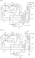
- FIG. 7 is a flowchart illustrating a sixth modified example of the natural gas liquefaction process of FIG. 1 .
- the second stream is recovered from the second heat exchange part 122 and then introduced into a compression unit 141 through a conduit 224 and compressed (a first compression step). Then, the second stream is introduced into a cooling unit 151 through a conduit 231 and cooled.
- the first stream is recovered from the first heat exchange part 121 and then introduced into a compression unit 142 through a conduit 213 and compressed (a second compression step). Then, the first stream is introduced into a cooling unit 152 through a conduit 291 and cooled.
- the first stream is mixed with the second stream within the conduit 292 through a conduit 2331 (a first mixing step).
- the main stream may be formed through the mixing.
- the main stream is introduced into a separation unit 112 and then separated into a third stream having a liquid phase and a fourth stream having a gas phase (a second separation step).
- the fourth stream is introduced into a compression unit 143 through a conduit 2332 and compressed (a third compression step).
- the fourth stream is mixed with the third stream (a second mixing step).
- the third stream may be forcibly transferred into a conduit 2334 by a pump 161.
- the main stream is introduced into a cooling unit 153 through a conduit 2334 and cooled.
- the main stream is partially condensed through the series of processes and introduced into a separation unit 111 through a conduit 234.
- a compressor has to be used for increasing a pressure of the refrigerant mixed in the first mixing step.
- the liquid refrigerant is generated in the first mixing step, it is impossible to directly introduce the liquid refrigerant into the compressor.
- the generated liquid refrigerant has to be separated and then increased in pressure by using the pump.
- FIG. 8 is a flowchart illustrating a natural gas liquefaction process according to the present invention.
- the liquefaction process according to the current embodiment may be similar to that according to the foregoing Example 1, particularly, the fifth modified example.
- the liquefaction process according to the current embodiment is the same as the forgoing fifth modified example except for a third heat exchange part.
- the same (equivalent) component as that according to the foregoing embodiment is given by the same (equivalent) reference number, and thus, their detailed description will be omitted.
- a second stream is introduced into a third heat exchange part 123 through a conduit 2211 (a second introduction step).
- the second stream is cooled by the second stream introduced into the third heat exchange part 123 through a conduit 2214.
- the second stream is introduced into a second heat exchange part 122 through a conduit 2212 (a third introduction step).
- the second stream is discharged from the second heat exchange part 122 and then introduced into an expansion unit 132 and expanded (a second expansion step).
- the second stream decreases in temperature through the above-described expansion.
- the second stream decreases in temperature due to the expansion and is introduced again into the second heat exchange part 122 through a conduit 2213 to cool natural gas in the second heat exchange part 122 (a second cooling step).
- the natural gas may be liquefied through the above-described cooling.
- the second stream performs the cooling in the second heat exchange part 122 and then is recovered from the second heat exchange part 122 through a conduit 2214 and introduced again into the third heat exchange part 123 (a fourth introduction step).
- the second stream may have some cool energy after the natural gas is cooled in the second heat exchange part 122.
- the liquefaction process according to the current embodiment is characterized in that the cool energy is used in the third heat exchange part 123.
- the second stream cools the second stream introduced into the third heat exchange part 123 through the conduit 2211.
- the second stream performs the cooling in the second heat exchange part and then recovered from the third heat exchange part 123 (a second recovery step).
- the second stream is recovered from the third heat exchange part 123 and then transferred for the condensation step through a conduit 2215.
- each of the first and second heat exchange parts 121 and 122 includes an SWHE-type heat exchanger.
- the third heat exchange part 123 may be an SWHE-type heat exchange or PFHE-type heat exchanger. That is, the third heat exchange part 123 is not particularly limited to the type of heat exchanger. However, the third heat exchange part 123 may be separately provided with respect to the first heat exchange part 121. (The third heat exchange part may be integrated with the second heat exchange part)
- FIG. 9 is a flowchart illustrating a modified embodiment of the natural gas liquefaction process of FIG. 8 .
- the second stream is separated into a first portion and a second portion.
- the above-described branch may be achieved by branching the other conduit 2216 from one conduit 2211. Alternatively, a separate constituent for the branch may be provided.
- the first portion may be introduced into the third heat exchange part 123. That is, in the liquefaction process according to the present invention the whole second stream is supplied into the third heat exchange part 123. However, in the liquefaction process according to the modified embodiment, only a portion of the second stream is supplied into the third heat exchange 123. Also, the second portion is introduced into the first heat exchange part 121 through a conduit 2216. Here, the second portion is cooled by the first stream introduced into the first heat exchange part 121 through the conduit 212. Then, the first and second portions are mixed again with each other and then introduced into the second heat exchange part 122 (see the conduits 2212 and 2217).
- the first portion of the second stream is cooled in the third heat exchange part 123, and the second portion of the second stream is cooled in the first heat exchange part 121. That is, in the liquefaction process according to the modified embodiment, the second stream is separated into the two portions, and then, the two portions are respectively cooled in the heat exchange parts different from each other.
- the liquefaction process according to the modified example it is unnecessary to cool the whole second stream in the third heat exchange part 123. Therefore, the liquefaction process according to the modified embodiment may be suitable when it is difficult to cool the whole second stream in the third heat exchange part 123.
- FIG. 10 is a flowchart illustrating a natural gas liquefaction process according to the present invention.
- the liquefaction process according to the current embodiment may be similar to that according to the foregoing Example 1, particularly, the fifth modified example.
- the liquefaction process according to the current embodiment is the same as the forgoing fifth modified example except for a third heat exchange part.
- the same (equivalent) component as that according to the foregoing embodiment is given by the same (equivalent) reference number, and thus, their detailed description will be omitted.
- a second stream is introduced into a first heat exchange part 121 through a conduit 2311 (a second introduction step).
- the second stream is cooled by a first stream introduced into the first heat exchange part 121 through a conduit 212.
- the second stream is introduced into a second heat exchange part 122 through a conduit 2312 (a third introduction step).
- the second stream is discharged from the second heat exchange part 122 and then introduced into an expansion unit 132 and expanded (a second expansion step).
- the second stream decreases in temperature through the above-described expansion.
- the second stream decreases in temperature due to the expansion and is introduced again into the second heat exchange part 122 through a conduit 2313 to cool natural gas in the second heat exchange part 122 (a second cooling step).
- the natural gas may be liquefied through the above-described cooling.
- the second stream performs the cooling in the second heat exchange part 122 and then is recovered from the second heat exchange part 122 through a conduit 2314 and introduced into the third heat exchange part 123.
- the second stream may have some cool energy after the natural gas is cooled in the second heat exchange part 122.
- the liquefaction process according to the current embodiment is characterized in that the cool energy is used in the third heat exchange part 123.
- the second stream cools the natural gas introduced into the third heat exchange part 123 through a conduit 311 (a third cooling step).
- the natural gas may be pre-cooled through the above-described cooling.
- the second stream performs the cooling in the second heat exchange part and then is recovered from the third heat exchange part 123 (a second recovery step).
- the second stream is recovered from the third heat exchange part 123 and then transferred for the condensation step through a conduit 2315.
- each of the first and second heat exchange parts 121 and 122 includes an SWHE-type heat exchanger.
- the third heat exchange part 123 may be an SWHE-type heat exchange or PFHE-type heat exchanger. That is, the third heat exchange part 123 is not particularly limited to the type of heat exchanger. However, the third heat exchange part 123 may be separately provided with respect to the first heat exchange part 121. (The third heat exchange part may be integrated with the second heat exchange part)
- FIG. 11 is a flowchart illustrating a modified embodiment of the natural gas liquefaction process of FIG. 10 .
- the natural gas is separated into a first portion and a second portion.
- the above-described branch may be achieved by branching one conduit into two conduits. Alternatively, a separate constituent for the branch may be provided.
- the first portion may be introduced into the third heat exchange part 123. That is, in the liquefaction process according to Embodiment 3, the whole natural gas is supplied into the third heat exchange part 123. However, in the liquefaction process according to the modified example, only a portion of the natural gas is supplied into the third heat exchange 123. Also, the second portion is introduced into the first heat exchange part 121 through a conduit 313. Here, the second portion is cooled by the first stream introduced into the first heat exchange part 121 through the conduit 212. Then, the first and second portions are mixed again with each other and then introduced together into the second heat exchange part 122 (see the conduits 312 and 314).
- the liquefaction process according to the modified example is characterized in that the natural gas is separated into the two portions, and then, the two portions are respectively cooled (pre-cooled) in the heat exchange parts different from each other.
Landscapes
- Engineering & Computer Science (AREA)
- Physics & Mathematics (AREA)
- Mechanical Engineering (AREA)
- Thermal Sciences (AREA)
- General Engineering & Computer Science (AREA)
- Chemical & Material Sciences (AREA)
- Chemical Kinetics & Catalysis (AREA)
- General Chemical & Material Sciences (AREA)
- Oil, Petroleum & Natural Gas (AREA)
- Analytical Chemistry (AREA)
- Power Engineering (AREA)
- Separation By Low-Temperature Treatments (AREA)
Priority Applications (1)
| Application Number | Priority Date | Filing Date | Title |
|---|---|---|---|
| EP17188470.3A EP3285034A3 (en) | 2013-05-20 | 2014-05-20 | Natural gas liquefaction process |
Applications Claiming Priority (2)
| Application Number | Priority Date | Filing Date | Title |
|---|---|---|---|
| KR20130056478 | 2013-05-20 | ||
| PCT/KR2014/004503 WO2014189261A1 (ko) | 2013-05-20 | 2014-05-20 | 천연가스 액화공정 |
Related Child Applications (2)
| Application Number | Title | Priority Date | Filing Date |
|---|---|---|---|
| EP17188470.3A Division EP3285034A3 (en) | 2013-05-20 | 2014-05-20 | Natural gas liquefaction process |
| EP17188470.3A Division-Into EP3285034A3 (en) | 2013-05-20 | 2014-05-20 | Natural gas liquefaction process |
Publications (3)
| Publication Number | Publication Date |
|---|---|
| EP3001128A1 EP3001128A1 (en) | 2016-03-30 |
| EP3001128A4 EP3001128A4 (en) | 2017-03-08 |
| EP3001128B1 true EP3001128B1 (en) | 2018-07-11 |
Family
ID=51933769
Family Applications (2)
| Application Number | Title | Priority Date | Filing Date |
|---|---|---|---|
| EP14800817.0A Active EP3001128B1 (en) | 2013-05-20 | 2014-05-20 | Natural gas liquefaction process |
| EP17188470.3A Withdrawn EP3285034A3 (en) | 2013-05-20 | 2014-05-20 | Natural gas liquefaction process |
Family Applications After (1)
| Application Number | Title | Priority Date | Filing Date |
|---|---|---|---|
| EP17188470.3A Withdrawn EP3285034A3 (en) | 2013-05-20 | 2014-05-20 | Natural gas liquefaction process |
Country Status (6)
| Country | Link |
|---|---|
| US (1) | US20160187056A1 (enExample) |
| EP (2) | EP3001128B1 (enExample) |
| KR (1) | KR101724226B1 (enExample) |
| AU (2) | AU2014269316B2 (enExample) |
| NO (1) | NO3001128T3 (enExample) |
| WO (1) | WO2014189261A1 (enExample) |
Families Citing this family (3)
| Publication number | Priority date | Publication date | Assignee | Title |
|---|---|---|---|---|
| US10480852B2 (en) | 2014-12-12 | 2019-11-19 | Dresser-Rand Company | System and method for liquefaction of natural gas |
| US10359228B2 (en) * | 2016-05-20 | 2019-07-23 | Air Products And Chemicals, Inc. | Liquefaction method and system |
| ES2736963B2 (es) * | 2018-07-03 | 2021-06-30 | Univ Coruna | Planta de compresión con conversión de energía residual en potencia eléctrica y refrigeración. |
Family Cites Families (15)
| Publication number | Priority date | Publication date | Assignee | Title |
|---|---|---|---|---|
| FR2292203A1 (fr) * | 1974-11-21 | 1976-06-18 | Technip Cie | Procede et installation pour la liquefaction d'un gaz a bas point d'ebullition |
| US4901533A (en) * | 1986-03-21 | 1990-02-20 | Linde Aktiengesellschaft | Process and apparatus for the liquefaction of a natural gas stream utilizing a single mixed refrigerant |
| US5657643A (en) * | 1996-02-28 | 1997-08-19 | The Pritchard Corporation | Closed loop single mixed refrigerant process |
| US6308531B1 (en) * | 1999-10-12 | 2001-10-30 | Air Products And Chemicals, Inc. | Hybrid cycle for the production of liquefied natural gas |
| TW480325B (en) * | 1999-12-01 | 2002-03-21 | Shell Int Research | Plant for liquefying natural gas |
| US7127914B2 (en) * | 2003-09-17 | 2006-10-31 | Air Products And Chemicals, Inc. | Hybrid gas liquefaction cycle with multiple expanders |
| DE102005010055A1 (de) * | 2005-03-04 | 2006-09-07 | Linde Ag | Verfahren zum Verflüssigen eines Kohlenwasserstoff-reichen Stromes |
| GB2455658B (en) * | 2006-09-22 | 2010-07-21 | Shell Int Research | Method and apparatus for producing a cooled hydrocarbon stream |
| BRPI0815707A2 (pt) * | 2007-08-24 | 2015-02-10 | Exxonmobil Upstream Res Co | Processo para a liquefação de uma corrente gasosa, e, sistema para o tratamento de uma corrente de alimentação gasosa. |
| US8464551B2 (en) * | 2008-11-18 | 2013-06-18 | Air Products And Chemicals, Inc. | Liquefaction method and system |
| EP2550496B1 (en) * | 2010-03-25 | 2017-06-14 | The University Of Manchester | Refrigeration process |
| CN101967413A (zh) * | 2010-06-07 | 2011-02-09 | 杭州福斯达实业集团有限公司 | 采用单一混合工质制冷来液化天然气的方法和装置 |
| WO2012023752A2 (ko) * | 2010-08-16 | 2012-02-23 | 한국가스공사연구개발원 | 천연가스 액화공정 |
| KR101056890B1 (ko) * | 2011-04-12 | 2011-08-12 | 한국가스공사연구개발원 | 천연가스 액화공정 |
| KR101037277B1 (ko) * | 2010-12-02 | 2011-05-26 | 한국가스공사연구개발원 | 천연가스 액화공정 |
-
2014
- 2014-05-20 NO NO14800817A patent/NO3001128T3/no unknown
- 2014-05-20 WO PCT/KR2014/004503 patent/WO2014189261A1/ko not_active Ceased
- 2014-05-20 KR KR1020157030595A patent/KR101724226B1/ko active Active
- 2014-05-20 EP EP14800817.0A patent/EP3001128B1/en active Active
- 2014-05-20 AU AU2014269316A patent/AU2014269316B2/en active Active
- 2014-05-20 EP EP17188470.3A patent/EP3285034A3/en not_active Withdrawn
- 2014-05-20 US US14/892,699 patent/US20160187056A1/en not_active Abandoned
-
2017
- 2017-05-03 AU AU2017202953A patent/AU2017202953A1/en not_active Abandoned
Non-Patent Citations (1)
| Title |
|---|
| None * |
Also Published As
| Publication number | Publication date |
|---|---|
| NO3001128T3 (enExample) | 2018-12-08 |
| EP3285034A2 (en) | 2018-02-21 |
| AU2014269316B2 (en) | 2017-05-25 |
| EP3001128A1 (en) | 2016-03-30 |
| KR101724226B1 (ko) | 2017-04-06 |
| AU2017202953A1 (en) | 2017-05-25 |
| KR20160009545A (ko) | 2016-01-26 |
| EP3285034A3 (en) | 2018-04-25 |
| US20160187056A1 (en) | 2016-06-30 |
| EP3001128A4 (en) | 2017-03-08 |
| AU2014269316A1 (en) | 2015-12-10 |
| WO2014189261A1 (ko) | 2014-11-27 |
Similar Documents
| Publication | Publication Date | Title |
|---|---|---|
| JP4938452B2 (ja) | 複数の膨張機を備えたハイブリッドガス液化サイクル | |
| AU2011292831B2 (en) | Natural gas liquefaction process | |
| RU2743094C2 (ru) | Улучшенный способ и система для охлаждения углеводородного потока с применением хладагента в газовой фазе | |
| KR20110122101A (ko) | 액화 천연 가스를 생성하는 방법 및 시스템 | |
| WO2011136544A2 (ko) | 냉매 분리가 있는 천연가스 액화공정 | |
| AU2011321145B2 (en) | Natural gas liquefaction process | |
| KR20180034251A (ko) | 혼합 냉매 냉각 공정 및 시스템 | |
| CN101189483A (zh) | 使富含烃类的流液化的方法 | |
| EP3001128B1 (en) | Natural gas liquefaction process | |
| KR101630518B1 (ko) | 천연가스 액화공정 | |
| KR101616626B1 (ko) | 천연가스 액화공정 | |
| CN102564061B (zh) | 一种应用于基荷型天然气液化工厂的双级混合冷剂循环液化系统 | |
| KR101037277B1 (ko) | 천연가스 액화공정 | |
| KR101620182B1 (ko) | 천연가스 액화공정 | |
| KR101620183B1 (ko) | 천연가스 액화공정 | |
| KR101464433B1 (ko) | 천연가스 액화공정 | |
| KR101615444B1 (ko) | 천연가스 액화공정 | |
| KR101615443B1 (ko) | 천연가스 액화공정 | |
| KR20190028894A (ko) | 익스펜더를 이용한 천연가스 메탄냉매 액화 시스템 |
Legal Events
| Date | Code | Title | Description |
|---|---|---|---|
| PUAI | Public reference made under article 153(3) epc to a published international application that has entered the european phase |
Free format text: ORIGINAL CODE: 0009012 |
|
| 17P | Request for examination filed |
Effective date: 20151119 |
|
| AK | Designated contracting states |
Kind code of ref document: A1 Designated state(s): AL AT BE BG CH CY CZ DE DK EE ES FI FR GB GR HR HU IE IS IT LI LT LU LV MC MK MT NL NO PL PT RO RS SE SI SK SM TR |
|
| AX | Request for extension of the european patent |
Extension state: BA ME |
|
| DAX | Request for extension of the european patent (deleted) | ||
| RIC1 | Information provided on ipc code assigned before grant |
Ipc: F25J 5/00 20060101ALI20161012BHEP Ipc: F25J 1/00 20060101AFI20161012BHEP |
|
| A4 | Supplementary search report drawn up and despatched |
Effective date: 20170207 |
|
| RIC1 | Information provided on ipc code assigned before grant |
Ipc: F25J 1/00 20060101AFI20170201BHEP Ipc: F25J 5/00 20060101ALI20170201BHEP |
|
| GRAP | Despatch of communication of intention to grant a patent |
Free format text: ORIGINAL CODE: EPIDOSNIGR1 |
|
| STAA | Information on the status of an ep patent application or granted ep patent |
Free format text: STATUS: GRANT OF PATENT IS INTENDED |
|
| INTG | Intention to grant announced |
Effective date: 20180130 |
|
| GRAS | Grant fee paid |
Free format text: ORIGINAL CODE: EPIDOSNIGR3 |
|
| GRAA | (expected) grant |
Free format text: ORIGINAL CODE: 0009210 |
|
| STAA | Information on the status of an ep patent application or granted ep patent |
Free format text: STATUS: THE PATENT HAS BEEN GRANTED |
|
| AK | Designated contracting states |
Kind code of ref document: B1 Designated state(s): AL AT BE BG CH CY CZ DE DK EE ES FI FR GB GR HR HU IE IS IT LI LT LU LV MC MK MT NL NO PL PT RO RS SE SI SK SM TR |
|
| REG | Reference to a national code |
Ref country code: GB Ref legal event code: FG4D |
|
| REG | Reference to a national code |
Ref country code: CH Ref legal event code: EP |
|
| REG | Reference to a national code |
Ref country code: AT Ref legal event code: REF Ref document number: 1017304 Country of ref document: AT Kind code of ref document: T Effective date: 20180715 |
|
| REG | Reference to a national code |
Ref country code: NO Ref legal event code: T2 Effective date: 20180711 |
|
| REG | Reference to a national code |
Ref country code: IE Ref legal event code: FG4D Ref country code: NL Ref legal event code: FP |
|
| REG | Reference to a national code |
Ref country code: DE Ref legal event code: R096 Ref document number: 602014028408 Country of ref document: DE |
|
| REG | Reference to a national code |
Ref country code: LT Ref legal event code: MG4D |
|
| REG | Reference to a national code |
Ref country code: AT Ref legal event code: MK05 Ref document number: 1017304 Country of ref document: AT Kind code of ref document: T Effective date: 20180711 |
|
| PG25 | Lapsed in a contracting state [announced via postgrant information from national office to epo] |
Ref country code: FI Free format text: LAPSE BECAUSE OF FAILURE TO SUBMIT A TRANSLATION OF THE DESCRIPTION OR TO PAY THE FEE WITHIN THE PRESCRIBED TIME-LIMIT Effective date: 20180711 Ref country code: SE Free format text: LAPSE BECAUSE OF FAILURE TO SUBMIT A TRANSLATION OF THE DESCRIPTION OR TO PAY THE FEE WITHIN THE PRESCRIBED TIME-LIMIT Effective date: 20180711 Ref country code: RS Free format text: LAPSE BECAUSE OF FAILURE TO SUBMIT A TRANSLATION OF THE DESCRIPTION OR TO PAY THE FEE WITHIN THE PRESCRIBED TIME-LIMIT Effective date: 20180711 Ref country code: IS Free format text: LAPSE BECAUSE OF FAILURE TO SUBMIT A TRANSLATION OF THE DESCRIPTION OR TO PAY THE FEE WITHIN THE PRESCRIBED TIME-LIMIT Effective date: 20181111 Ref country code: AT Free format text: LAPSE BECAUSE OF FAILURE TO SUBMIT A TRANSLATION OF THE DESCRIPTION OR TO PAY THE FEE WITHIN THE PRESCRIBED TIME-LIMIT Effective date: 20180711 Ref country code: LT Free format text: LAPSE BECAUSE OF FAILURE TO SUBMIT A TRANSLATION OF THE DESCRIPTION OR TO PAY THE FEE WITHIN THE PRESCRIBED TIME-LIMIT Effective date: 20180711 Ref country code: PL Free format text: LAPSE BECAUSE OF FAILURE TO SUBMIT A TRANSLATION OF THE DESCRIPTION OR TO PAY THE FEE WITHIN THE PRESCRIBED TIME-LIMIT Effective date: 20180711 Ref country code: GR Free format text: LAPSE BECAUSE OF FAILURE TO SUBMIT A TRANSLATION OF THE DESCRIPTION OR TO PAY THE FEE WITHIN THE PRESCRIBED TIME-LIMIT Effective date: 20181012 Ref country code: BG Free format text: LAPSE BECAUSE OF FAILURE TO SUBMIT A TRANSLATION OF THE DESCRIPTION OR TO PAY THE FEE WITHIN THE PRESCRIBED TIME-LIMIT Effective date: 20181011 |
|
| PG25 | Lapsed in a contracting state [announced via postgrant information from national office to epo] |
Ref country code: AL Free format text: LAPSE BECAUSE OF FAILURE TO SUBMIT A TRANSLATION OF THE DESCRIPTION OR TO PAY THE FEE WITHIN THE PRESCRIBED TIME-LIMIT Effective date: 20180711 Ref country code: ES Free format text: LAPSE BECAUSE OF FAILURE TO SUBMIT A TRANSLATION OF THE DESCRIPTION OR TO PAY THE FEE WITHIN THE PRESCRIBED TIME-LIMIT Effective date: 20180711 Ref country code: HR Free format text: LAPSE BECAUSE OF FAILURE TO SUBMIT A TRANSLATION OF THE DESCRIPTION OR TO PAY THE FEE WITHIN THE PRESCRIBED TIME-LIMIT Effective date: 20180711 Ref country code: LV Free format text: LAPSE BECAUSE OF FAILURE TO SUBMIT A TRANSLATION OF THE DESCRIPTION OR TO PAY THE FEE WITHIN THE PRESCRIBED TIME-LIMIT Effective date: 20180711 |
|
| REG | Reference to a national code |
Ref country code: DE Ref legal event code: R097 Ref document number: 602014028408 Country of ref document: DE |
|
| PG25 | Lapsed in a contracting state [announced via postgrant information from national office to epo] |
Ref country code: EE Free format text: LAPSE BECAUSE OF FAILURE TO SUBMIT A TRANSLATION OF THE DESCRIPTION OR TO PAY THE FEE WITHIN THE PRESCRIBED TIME-LIMIT Effective date: 20180711 Ref country code: CZ Free format text: LAPSE BECAUSE OF FAILURE TO SUBMIT A TRANSLATION OF THE DESCRIPTION OR TO PAY THE FEE WITHIN THE PRESCRIBED TIME-LIMIT Effective date: 20180711 Ref country code: RO Free format text: LAPSE BECAUSE OF FAILURE TO SUBMIT A TRANSLATION OF THE DESCRIPTION OR TO PAY THE FEE WITHIN THE PRESCRIBED TIME-LIMIT Effective date: 20180711 |
|
| PLBE | No opposition filed within time limit |
Free format text: ORIGINAL CODE: 0009261 |
|
| STAA | Information on the status of an ep patent application or granted ep patent |
Free format text: STATUS: NO OPPOSITION FILED WITHIN TIME LIMIT |
|
| PG25 | Lapsed in a contracting state [announced via postgrant information from national office to epo] |
Ref country code: SM Free format text: LAPSE BECAUSE OF FAILURE TO SUBMIT A TRANSLATION OF THE DESCRIPTION OR TO PAY THE FEE WITHIN THE PRESCRIBED TIME-LIMIT Effective date: 20180711 Ref country code: DK Free format text: LAPSE BECAUSE OF FAILURE TO SUBMIT A TRANSLATION OF THE DESCRIPTION OR TO PAY THE FEE WITHIN THE PRESCRIBED TIME-LIMIT Effective date: 20180711 Ref country code: SK Free format text: LAPSE BECAUSE OF FAILURE TO SUBMIT A TRANSLATION OF THE DESCRIPTION OR TO PAY THE FEE WITHIN THE PRESCRIBED TIME-LIMIT Effective date: 20180711 |
|
| 26N | No opposition filed |
Effective date: 20190412 |
|
| PG25 | Lapsed in a contracting state [announced via postgrant information from national office to epo] |
Ref country code: SI Free format text: LAPSE BECAUSE OF FAILURE TO SUBMIT A TRANSLATION OF THE DESCRIPTION OR TO PAY THE FEE WITHIN THE PRESCRIBED TIME-LIMIT Effective date: 20180711 |
|
| REG | Reference to a national code |
Ref country code: CH Ref legal event code: PL |
|
| PG25 | Lapsed in a contracting state [announced via postgrant information from national office to epo] |
Ref country code: LI Free format text: LAPSE BECAUSE OF NON-PAYMENT OF DUE FEES Effective date: 20190531 Ref country code: MC Free format text: LAPSE BECAUSE OF FAILURE TO SUBMIT A TRANSLATION OF THE DESCRIPTION OR TO PAY THE FEE WITHIN THE PRESCRIBED TIME-LIMIT Effective date: 20180711 Ref country code: CH Free format text: LAPSE BECAUSE OF NON-PAYMENT OF DUE FEES Effective date: 20190531 |
|
| REG | Reference to a national code |
Ref country code: BE Ref legal event code: MM Effective date: 20190531 |
|
| PG25 | Lapsed in a contracting state [announced via postgrant information from national office to epo] |
Ref country code: LU Free format text: LAPSE BECAUSE OF NON-PAYMENT OF DUE FEES Effective date: 20190520 |
|
| PG25 | Lapsed in a contracting state [announced via postgrant information from national office to epo] |
Ref country code: TR Free format text: LAPSE BECAUSE OF FAILURE TO SUBMIT A TRANSLATION OF THE DESCRIPTION OR TO PAY THE FEE WITHIN THE PRESCRIBED TIME-LIMIT Effective date: 20180711 |
|
| PG25 | Lapsed in a contracting state [announced via postgrant information from national office to epo] |
Ref country code: IE Free format text: LAPSE BECAUSE OF NON-PAYMENT OF DUE FEES Effective date: 20190520 |
|
| PG25 | Lapsed in a contracting state [announced via postgrant information from national office to epo] |
Ref country code: BE Free format text: LAPSE BECAUSE OF NON-PAYMENT OF DUE FEES Effective date: 20190531 |
|
| PG25 | Lapsed in a contracting state [announced via postgrant information from national office to epo] |
Ref country code: PT Free format text: LAPSE BECAUSE OF FAILURE TO SUBMIT A TRANSLATION OF THE DESCRIPTION OR TO PAY THE FEE WITHIN THE PRESCRIBED TIME-LIMIT Effective date: 20181111 |
|
| PG25 | Lapsed in a contracting state [announced via postgrant information from national office to epo] |
Ref country code: CY Free format text: LAPSE BECAUSE OF FAILURE TO SUBMIT A TRANSLATION OF THE DESCRIPTION OR TO PAY THE FEE WITHIN THE PRESCRIBED TIME-LIMIT Effective date: 20180711 |
|
| PG25 | Lapsed in a contracting state [announced via postgrant information from national office to epo] |
Ref country code: HU Free format text: LAPSE BECAUSE OF FAILURE TO SUBMIT A TRANSLATION OF THE DESCRIPTION OR TO PAY THE FEE WITHIN THE PRESCRIBED TIME-LIMIT; INVALID AB INITIO Effective date: 20140520 Ref country code: MT Free format text: LAPSE BECAUSE OF FAILURE TO SUBMIT A TRANSLATION OF THE DESCRIPTION OR TO PAY THE FEE WITHIN THE PRESCRIBED TIME-LIMIT Effective date: 20180711 |
|
| PG25 | Lapsed in a contracting state [announced via postgrant information from national office to epo] |
Ref country code: MK Free format text: LAPSE BECAUSE OF FAILURE TO SUBMIT A TRANSLATION OF THE DESCRIPTION OR TO PAY THE FEE WITHIN THE PRESCRIBED TIME-LIMIT Effective date: 20180711 |
|
| REG | Reference to a national code |
Ref country code: FR Ref legal event code: PLFP Year of fee payment: 10 |
|
| PGFP | Annual fee paid to national office [announced via postgrant information from national office to epo] |
Ref country code: NL Payment date: 20250317 Year of fee payment: 12 |
|
| PGFP | Annual fee paid to national office [announced via postgrant information from national office to epo] |
Ref country code: DE Payment date: 20250325 Year of fee payment: 12 |
|
| PGFP | Annual fee paid to national office [announced via postgrant information from national office to epo] |
Ref country code: NO Payment date: 20250509 Year of fee payment: 12 |
|
| PGFP | Annual fee paid to national office [announced via postgrant information from national office to epo] |
Ref country code: IT Payment date: 20250422 Year of fee payment: 12 |
|
| REG | Reference to a national code |
Ref country code: DE Ref legal event code: R082 Ref document number: 602014028408 Country of ref document: DE Representative=s name: VUILLERMOZ, BRUNO, FR |
|
| PGFP | Annual fee paid to national office [announced via postgrant information from national office to epo] |
Ref country code: GB Payment date: 20260313 Year of fee payment: 13 |
|
| PGFP | Annual fee paid to national office [announced via postgrant information from national office to epo] |
Ref country code: FR Payment date: 20260309 Year of fee payment: 13 |