EP3001060A1 - Torque transmission shaft with yoke for universal joint and manufacturing method therefor - Google Patents
Torque transmission shaft with yoke for universal joint and manufacturing method therefor Download PDFInfo
- Publication number
- EP3001060A1 EP3001060A1 EP14832831.3A EP14832831A EP3001060A1 EP 3001060 A1 EP3001060 A1 EP 3001060A1 EP 14832831 A EP14832831 A EP 14832831A EP 3001060 A1 EP3001060 A1 EP 3001060A1
- Authority
- EP
- European Patent Office
- Prior art keywords
- torque transmission
- end portion
- transmission shaft
- rod
- axial end
- Prior art date
- Legal status (The legal status is an assumption and is not a legal conclusion. Google has not performed a legal analysis and makes no representation as to the accuracy of the status listed.)
- Granted
Links
Images





Classifications
-
- F—MECHANICAL ENGINEERING; LIGHTING; HEATING; WEAPONS; BLASTING
- F16—ENGINEERING ELEMENTS AND UNITS; GENERAL MEASURES FOR PRODUCING AND MAINTAINING EFFECTIVE FUNCTIONING OF MACHINES OR INSTALLATIONS; THERMAL INSULATION IN GENERAL
- F16D—COUPLINGS FOR TRANSMITTING ROTATION; CLUTCHES; BRAKES
- F16D1/00—Couplings for rigidly connecting two coaxial shafts or other movable machine elements
- F16D1/10—Quick-acting couplings in which the parts are connected by simply bringing them together axially
- F16D1/101—Quick-acting couplings in which the parts are connected by simply bringing them together axially without axial retaining means rotating with the coupling
-
- B—PERFORMING OPERATIONS; TRANSPORTING
- B29—WORKING OF PLASTICS; WORKING OF SUBSTANCES IN A PLASTIC STATE IN GENERAL
- B29C—SHAPING OR JOINING OF PLASTICS; SHAPING OF MATERIAL IN A PLASTIC STATE, NOT OTHERWISE PROVIDED FOR; AFTER-TREATMENT OF THE SHAPED PRODUCTS, e.g. REPAIRING
- B29C43/00—Compression moulding, i.e. applying external pressure to flow the moulding material; Apparatus therefor
- B29C43/02—Compression moulding, i.e. applying external pressure to flow the moulding material; Apparatus therefor of articles of definite length, i.e. discrete articles
- B29C43/16—Forging
-
- B—PERFORMING OPERATIONS; TRANSPORTING
- B29—WORKING OF PLASTICS; WORKING OF SUBSTANCES IN A PLASTIC STATE IN GENERAL
- B29C—SHAPING OR JOINING OF PLASTICS; SHAPING OF MATERIAL IN A PLASTIC STATE, NOT OTHERWISE PROVIDED FOR; AFTER-TREATMENT OF THE SHAPED PRODUCTS, e.g. REPAIRING
- B29C43/00—Compression moulding, i.e. applying external pressure to flow the moulding material; Apparatus therefor
- B29C43/02—Compression moulding, i.e. applying external pressure to flow the moulding material; Apparatus therefor of articles of definite length, i.e. discrete articles
- B29C43/18—Compression moulding, i.e. applying external pressure to flow the moulding material; Apparatus therefor of articles of definite length, i.e. discrete articles incorporating preformed parts or layers, e.g. compression moulding around inserts or for coating articles
-
- B—PERFORMING OPERATIONS; TRANSPORTING
- B62—LAND VEHICLES FOR TRAVELLING OTHERWISE THAN ON RAILS
- B62D—MOTOR VEHICLES; TRAILERS
- B62D1/00—Steering controls, i.e. means for initiating a change of direction of the vehicle
- B62D1/02—Steering controls, i.e. means for initiating a change of direction of the vehicle vehicle-mounted
- B62D1/16—Steering columns
-
- B—PERFORMING OPERATIONS; TRANSPORTING
- B62—LAND VEHICLES FOR TRAVELLING OTHERWISE THAN ON RAILS
- B62D—MOTOR VEHICLES; TRAILERS
- B62D1/00—Steering controls, i.e. means for initiating a change of direction of the vehicle
- B62D1/02—Steering controls, i.e. means for initiating a change of direction of the vehicle vehicle-mounted
- B62D1/16—Steering columns
- B62D1/20—Connecting steering column to steering gear
-
- F—MECHANICAL ENGINEERING; LIGHTING; HEATING; WEAPONS; BLASTING
- F16—ENGINEERING ELEMENTS AND UNITS; GENERAL MEASURES FOR PRODUCING AND MAINTAINING EFFECTIVE FUNCTIONING OF MACHINES OR INSTALLATIONS; THERMAL INSULATION IN GENERAL
- F16C—SHAFTS; FLEXIBLE SHAFTS; ELEMENTS OR CRANKSHAFT MECHANISMS; ROTARY BODIES OTHER THAN GEARING ELEMENTS; BEARINGS
- F16C3/00—Shafts; Axles; Cranks; Eccentrics
- F16C3/02—Shafts; Axles
- F16C3/03—Shafts; Axles telescopic
-
- F—MECHANICAL ENGINEERING; LIGHTING; HEATING; WEAPONS; BLASTING
- F16—ENGINEERING ELEMENTS AND UNITS; GENERAL MEASURES FOR PRODUCING AND MAINTAINING EFFECTIVE FUNCTIONING OF MACHINES OR INSTALLATIONS; THERMAL INSULATION IN GENERAL
- F16D—COUPLINGS FOR TRANSMITTING ROTATION; CLUTCHES; BRAKES
- F16D3/00—Yielding couplings, i.e. with means permitting movement between the connected parts during the drive
- F16D3/16—Universal joints in which flexibility is produced by means of pivots or sliding or rolling connecting parts
- F16D3/26—Hooke's joints or other joints with an equivalent intermediate member to which each coupling part is pivotally or slidably connected
- F16D3/38—Hooke's joints or other joints with an equivalent intermediate member to which each coupling part is pivotally or slidably connected with a single intermediate member with trunnions or bearings arranged on two axes perpendicular to one another
- F16D3/382—Hooke's joints or other joints with an equivalent intermediate member to which each coupling part is pivotally or slidably connected with a single intermediate member with trunnions or bearings arranged on two axes perpendicular to one another constructional details of other than the intermediate member
- F16D3/387—Fork construction; Mounting of fork on shaft; Adapting shaft for mounting of fork
-
- B—PERFORMING OPERATIONS; TRANSPORTING
- B29—WORKING OF PLASTICS; WORKING OF SUBSTANCES IN A PLASTIC STATE IN GENERAL
- B29L—INDEXING SCHEME ASSOCIATED WITH SUBCLASS B29C, RELATING TO PARTICULAR ARTICLES
- B29L2031/00—Other particular articles
- B29L2031/748—Machines or parts thereof not otherwise provided for
- B29L2031/75—Shafts
-
- F—MECHANICAL ENGINEERING; LIGHTING; HEATING; WEAPONS; BLASTING
- F16—ENGINEERING ELEMENTS AND UNITS; GENERAL MEASURES FOR PRODUCING AND MAINTAINING EFFECTIVE FUNCTIONING OF MACHINES OR INSTALLATIONS; THERMAL INSULATION IN GENERAL
- F16C—SHAFTS; FLEXIBLE SHAFTS; ELEMENTS OR CRANKSHAFT MECHANISMS; ROTARY BODIES OTHER THAN GEARING ELEMENTS; BEARINGS
- F16C2326/00—Articles relating to transporting
- F16C2326/20—Land vehicles
- F16C2326/24—Steering systems, e.g. steering rods or columns
-
- F—MECHANICAL ENGINEERING; LIGHTING; HEATING; WEAPONS; BLASTING
- F16—ENGINEERING ELEMENTS AND UNITS; GENERAL MEASURES FOR PRODUCING AND MAINTAINING EFFECTIVE FUNCTIONING OF MACHINES OR INSTALLATIONS; THERMAL INSULATION IN GENERAL
- F16D—COUPLINGS FOR TRANSMITTING ROTATION; CLUTCHES; BRAKES
- F16D1/00—Couplings for rigidly connecting two coaxial shafts or other movable machine elements
- F16D1/06—Couplings for rigidly connecting two coaxial shafts or other movable machine elements for attachment of a member on a shaft or on a shaft-end
- F16D1/08—Couplings for rigidly connecting two coaxial shafts or other movable machine elements for attachment of a member on a shaft or on a shaft-end with clamping hub; with hub and longitudinal key
- F16D1/0852—Couplings for rigidly connecting two coaxial shafts or other movable machine elements for attachment of a member on a shaft or on a shaft-end with clamping hub; with hub and longitudinal key with radial clamping between the mating surfaces of the hub and shaft
- F16D1/0858—Couplings for rigidly connecting two coaxial shafts or other movable machine elements for attachment of a member on a shaft or on a shaft-end with clamping hub; with hub and longitudinal key with radial clamping between the mating surfaces of the hub and shaft due to the elasticity of the hub (including shrink fits)
-
- F—MECHANICAL ENGINEERING; LIGHTING; HEATING; WEAPONS; BLASTING
- F16—ENGINEERING ELEMENTS AND UNITS; GENERAL MEASURES FOR PRODUCING AND MAINTAINING EFFECTIVE FUNCTIONING OF MACHINES OR INSTALLATIONS; THERMAL INSULATION IN GENERAL
- F16D—COUPLINGS FOR TRANSMITTING ROTATION; CLUTCHES; BRAKES
- F16D1/00—Couplings for rigidly connecting two coaxial shafts or other movable machine elements
- F16D1/10—Quick-acting couplings in which the parts are connected by simply bringing them together axially
- F16D2001/103—Quick-acting couplings in which the parts are connected by simply bringing them together axially the torque is transmitted via splined connections
-
- F—MECHANICAL ENGINEERING; LIGHTING; HEATING; WEAPONS; BLASTING
- F16—ENGINEERING ELEMENTS AND UNITS; GENERAL MEASURES FOR PRODUCING AND MAINTAINING EFFECTIVE FUNCTIONING OF MACHINES OR INSTALLATIONS; THERMAL INSULATION IN GENERAL
- F16D—COUPLINGS FOR TRANSMITTING ROTATION; CLUTCHES; BRAKES
- F16D3/00—Yielding couplings, i.e. with means permitting movement between the connected parts during the drive
- F16D3/16—Universal joints in which flexibility is produced by means of pivots or sliding or rolling connecting parts
- F16D3/20—Universal joints in which flexibility is produced by means of pivots or sliding or rolling connecting parts one coupling part entering a sleeve of the other coupling part and connected thereto by sliding or rolling members
- F16D3/22—Universal joints in which flexibility is produced by means of pivots or sliding or rolling connecting parts one coupling part entering a sleeve of the other coupling part and connected thereto by sliding or rolling members the rolling members being balls, rollers, or the like, guided in grooves or sockets in both coupling parts
- F16D3/223—Universal joints in which flexibility is produced by means of pivots or sliding or rolling connecting parts one coupling part entering a sleeve of the other coupling part and connected thereto by sliding or rolling members the rolling members being balls, rollers, or the like, guided in grooves or sockets in both coupling parts the rolling members being guided in grooves in both coupling parts
- F16D2003/22326—Attachments to the outer joint member, i.e. attachments to the exterior of the outer joint member or to the shaft of the outer joint member
-
- Y—GENERAL TAGGING OF NEW TECHNOLOGICAL DEVELOPMENTS; GENERAL TAGGING OF CROSS-SECTIONAL TECHNOLOGIES SPANNING OVER SEVERAL SECTIONS OF THE IPC; TECHNICAL SUBJECTS COVERED BY FORMER USPC CROSS-REFERENCE ART COLLECTIONS [XRACs] AND DIGESTS
- Y10—TECHNICAL SUBJECTS COVERED BY FORMER USPC
- Y10T—TECHNICAL SUBJECTS COVERED BY FORMER US CLASSIFICATION
- Y10T403/00—Joints and connections
- Y10T403/70—Interfitted members
- Y10T403/7026—Longitudinally splined or fluted rod
- Y10T403/7035—Specific angle or shape of rib, key, groove, or shoulder
Definitions
- the present invention relates to a torque transmission shaft having a universal joint yoke for configuring an intermediate shaft which configures, for example, an automobile steering apparatus and is configured to transmit rotation of a steering shaft to an input shaft of a steering gear unit, and relates to a method of manufacturing the same.
- a steering apparatus shown in FIG. 11 has been conventionally used as an automobile steering apparatus.
- the steering apparatus is configured to convert rotational motion of a steering wheel 1 operated by a driver into linear motion at a steering gear unit 2, thereby applying a desired steering angle to left and right steering wheels (not shown).
- the steering wheel 1 is fixed to a rear end portion of a steering shaft 3.
- a front end portion of the steering shaft 3 is coupled to a base end portion of an input shaft 6 of the steering gear unit 2 through a pair of universal joints 4a, 4b and an intermediate shaft 5.
- the steering apparatus configured as described above, when the driver operates the steering wheel 1, the rotation of the steering wheel 1 is transmitted to the pinion shaft 6 through the steering shaft 3, the universal joints 4a, 4b and the intermediate shaft 5. As a result, the rack shaft is displaced in a shaft direction (a width direction of a vehicle body) and the tie rods 7, 7 are thus pushed or pulled, so that the desired steering angle is applied to the left and right steering wheels.
- the intermediate shaft 5 configuring the steering apparatus as described above is required to have not only a function of transmitting the torque between the universal joints 4a, 4b but also a function of expanding and contracting an entire length thereof due to one or both of following reasons (1) and (2).
- An interval between the universal joints 4a, 4b may be varied depending on position adjustment of the steering wheel 1 in a front-rear direction.
- the steering gear unit 2 At collision accident, as an automobile primarily collides with another automobile and the like, the steering gear unit 2 is strongly pushed rearwards. If the movement of the steering unit 2 is transmitted to the steering shaft 3, as it is, the steering wheel 1 supported and fixed to the rear end portion of the steering shaft 3 is furiously displaced (pushed up) towards the body of the driver, so that it is difficult to protect the driver. Therefore, the intermediate shaft 5 is configured so that the entire length is contracted by shock load resulting from the primary collision. Thereby, the movement of the steering gear unit 2 resulting from the primary collision is not transmitted, as it is, to the steering shaft 3. Incidentally, in order to achieve this function, the load necessary to expand and contract the intermediate shaft 5 may be large to some extent.
- the intermediate shaft 5 configuring the steering apparatus is required to have the function of expanding and contracting the entire length thereof, in addition to the function of transmitting the torque, as described above.
- the intermediate shaft 5 having those functions has been conventionally widely used (for example, refer to Patent Documents 1 and 2).
- FIGS. 12 , 13A and 13B illustrate an example of the intermediate shaft 5 conventionally widely used.
- the intermediate shaft 5 has a pair of torque transmission shafts 8a, 8b having a round rod shape or round tube shape.
- Base end portions of yokes 9, 9 for configuring universal joints 4a, 4b are respectively coupled and fixed to axially outer end portions (base end portions at opposite sides) of the torque transmission shafts 8a, 8b.
- the universal joints 4a, 4b are respectively configured to couple other yokes 9a, 9b to tip portions of the yokes 9, 9 through cross shafts 10 so that the torque can be transmitted between the respective yokes 9, 9a, 9b even at a state where central axes of the yokes 9, 9a, 9b are inclined relative to each other.
- a tip portion (a left end portion in FIG. 12 ) of the torque transmission shaft 8a having the round rod shape of the torque transmission shafts 8a, 8b configuring the intermediate shaft 5 is made to have a larger diameter than an intermediate part thereof and male spline teeth are formed on an outer periphery of the large diameter part, so that a male spline part 11 is provided on the outer periphery of the tip portion of the torque transmission shaft 8a.
- a groove bottom diameter d 11 of the male spline part 11 is made to be larger than an outer diameter D 8a of the intermediate part of the torque transmission shaft 8a (d 11 >D 8a ), so that the large diameter part can be formed with the male spline teeth by broach processing, which is a type of cutting processing.
- an inner periphery of the torque transmission shaft 8b having the round tube shape is formed with female spline teeth over a substantial entire length of the inner periphery of the torque transmission shaft 8b, so that the substantial entire inner periphery of the torque transmission shaft 8b is formed as a female spline part 18.
- the male spline part 11 formed on the outer periphery of the tip portion of the torque transmission shaft 8a having the round rod shape is engaged with the female spline part 18 provided on the inner periphery of the torque transmission shaft 8b having the round tube shape, so that it is possible to obtain the intermediate shaft 5, of which an entire length can be expanded and contracted by the torque transmission shaft 8a and the torque transmission shaft 8b.
- the spline parts 11, 18 are axially displaced by small force, it is possible to obtain the functions corresponding to the above (1) and (2).
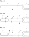
- FIGS. 14A to 14C illustrate an example of a conventional method of manufacturing a torque transmission shaft having a universal joint yoke, in which the torque transmission shaft 8a having the round rod shape and the yoke 9 are integrally formed.
- plastic working such as forge processing is performed for a hollow or solid metal material such as medium-carbon steel, so that a first intermediate material 12 as shown in FIG. 14A is obtained.
- One axial half part (a part except for the other axial end portion, a left part of FIGS. 14A to 14C ) of the first intermediate material 12 is formed as a first base rod part 13 having an outer diameter D 13 which is constant over a substantial entire length, and a base end portion of the yoke 9 is fixed to the other axial end portion (a right end portion in FIGS. 14A to 14C ) of the first base rod part 13, so that the first base rod part 13 and the yoke 9 are integrally formed.
- the outer diameter D 13 of the first base rod part 13 is larger than the outer diameter D 8a of the intermediate part (the part axially distant from the male spline part 11 and the yoke 9) of the completed torque transmission shaft 8a having the round rod shape shown in FIGS. 12 , 13A and 13B and is substantially the same as a tooth tip circle diameter (a circumscribed circle diameter) D 11 of the male spline part 11 (D 11 ⁇ D 13 >D 8a ).
- the cutting processing such as turning machining is performed for the other axial end portion (an axially intermediate part of the first intermediate material 12) of the first base rod part 13, so that a second intermediate material 14 as shown in FIG. 14B is obtained.
- an outer diameter D 15 of the other axial end portion (an axially intermediate part of the second intermediate material 14) of a second base rod part 15 provided at one axial half part thereof is made substantially the same as the outer diameter D 8a (D 15 ⁇ D 8a ) of the intermediate part of the completed torque transmission shaft 8a having the round rod shape and one axial end portion is provided with a large diameter part 16 having an outer diameter which is larger than the other axial end portion.
- an outer periphery of the larger diameter part 16 is formed with male spline teeth, so that the outer periphery of the corresponding part is provided with the male spline part 11.
- a torque transmission shaft 17 having a universal joint yoke in which the torque transmission shaft 8a having the round rod shape and the yoke 9 are integrally formed, is obtained.
- the torque transmission shaft 17 having the universal joint yoke it is not necessary to perform an operation of coupling and fixing the torque transmission shaft 8a and the yoke 9 by the welding and like and it is possible to increase the strength of the coupling part, which are advantageous to the saving of the cost of the intermediate shaft 5 and the improvement on the strength thereof, like the conventional structure shown in FIG. 12 .
- the groove bottom diameter d 11 of the male spline part 11 is increased beyond necessity, so that it is difficult to reduce a weight of the entire intermediate shaft 5 including the torque transmission shaft 17 having the universal joint yoke.
- a torque transmission shaft having a universal joint yoke includes: a rod part which has a round rod shape and includes a male spline part provided on an outer periphery of one axial end portion thereof; and a yoke which is fixed to another axial end portion of the rod part and includes a pair of arm parts configured to pivotally support end portions of a cross shaft configuring a cross shaft type universal joint, wherein a groove bottom diameter of the male spline part is smaller than an outer diameter of a part of the rod part axially distant from the male spline part.
- a surface of the male spline part may be provided with a coating layer made of a low friction material.
- a groove bottom layer formed on a groove bottom of the male spline part may have a diametrical thickness larger than a diametrical thickness of a tooth tip layer formed on a tooth tip portion of the male spline part.
- a sectional shape of a spline groove of the male spline part may be a partial arc shape.
- a telescopic shaft including the above torque transmission shaft having the universal joint yoke, and another torque transmission shaft which has a round tube shape at least at the other axial end portion and includes a female spline part formed on an inner periphery of the other axial end portion and configured to be spline-engaged with the male spline part, so that the torque can be transmitted between the torque transmission shaft having the universal joint yoke and the other torque transmission shaft, and the torque transmission shaft having the universal joint yoke can be relatively moved with the other torque transmission shaft.
- a part of the rod part axially distant from the male spline part may have an outer diameter smaller than an inscribed circle diameter of the female spline part of the other torque transmission shaft
- a method of manufacturing a torque transmission shaft having a universal joint yoke according to the present invention in order to manufacture the above torque transmission shaft having the universal joint yoke, includes providing a rod-shaped element to which the yoke is fixed at another axial end portion thereof, an outer diameter of an axial half part of the rod-shaped element being the same as an outer diameter of the finished rod part at a side of the axial end portion thereof (a part of the rod part axially distant from the male spline part); and performing plastic working for deforming an outer periphery of one axial end portion of the rod-shaped element, on the outer periphery of the one axial end portion, thereby forming the male spline part on the outer periphery of the one axial end portion of the rod-shaped element such that the male spline part has a groove bottom diameter smaller than an outer diameter of the rod part at a side of the other axial end portion thereof and has a tooth tip diameter larger than the outer diameter of the rod part at the side of the other
- the plastic working may be forge processing of pressing a mold which has a processing surface of a shape conforming to an outer surface shape of the male spline part, to the outer periphery of the one axial end portion of the rod-shaped element.
- a sectional shape of a spline groove of the male spline part may be a partial arc shape.
- the term 'spline' described in the specification and the claims includes a general spline of which a circumferential pitch of teeth and grooves is larger, and also one referred to as serration of which a circumferential pitch of teeth is smaller.
- the torque transmission shaft having the universal joint yoke and the manufacturing method thereof as described above it is possible to save the manufacturing cost and to easily reduce the weight thereof.
- one axial end portion is crushed diametrically inwards at the plurality of circumferential places, so that the plurality of spline groove portions, each of which extends axially, are formed.
- the extra thicknesses extruded from the respective spline groove portions are projected (uphove) diametrically outwards between the circumferentially adjacent spline groove portions, so that the plurality of spline teeth, each of which extends axially, are formed between the respective spline groove portions.
- FIG. 1 illustrates a completed torque transmission shaft 17a having a universal joint yoke according to this embodiment.
- the torque transmission shaft 17a having the universal joint yoke is provided on an outer periphery of one axial end portion (a left end portion in FIG. 1 ) of a rod part 19 having a circular section with a male spline part 11a, and a base end portion of a yoke 9 having a pair of arm parts 20, 20 for pivotally supporting two end portions, which are diametrically opposite to each other, of four end portions of the cross shaft 10 (refer to FIG.
- a groove bottom diameter d 11 of the male spline part 11a is made to be smaller than an outer diameter D 19 of the other axial end side part (a part of the rod part 19 axially distant from the male spline part 11a) of the rod part 19 (d 11 ⁇ D 19 ). As shown in FIGS.
- the male spline part 11a of the torque transmission shaft 17a having the universal joint yoke is spline-engaged with a female spline part 18 provided on an inner periphery of the other torque transmission shaft 8b having a round tube shape.
- the torque can be transmitted between the torque transmission shaft having the universal joint yoke and the other torque transmission shaft 8b, and the intermediate shaft (refer to FIGS. 11 to 13 ) of which axial size can be expanded and contracted is configured.
- the torque transmission shaft 17a having the universal joint yoke as described above is made by performing only plastic working for a hollow or solid rod-shaped metal material, in principle. That is, even though cutting processing and grinding processing may be performed for finishing, the cutting processing and grinding processing causing a shape and a size to be changed are not performed in principle, except for a chamfering of an end portion, for example.
- a rod-shaped element 21 as shown in FIGS. 3A and 4A is first made by performing the plastic working such as press working and forge processing for a metal material such as carbon steel and stainless steel.
- the plastic working for making the rod-shaped element 21 is the same as the plastic working for making the first intermediate material 12, except that the outer diameter D 21 of the rod-shaped element 21 is made to be smaller than the outer diameter D 13 of the first base rod part 13 of the conventional first intermediate material 12 shown in FIG. 14A and to be substantially the same as the outer diameter D 8a of the intermediate part of the completed torque transmission shaft 8a shown in FIG. 14C (D 13 >D 21 ⁇ D 8a ). Also, since the well-known method can be applied to a method of implementing the plastic working for making the rod-shaped element 21, the specific illustration and description thereof will be omitted.
- the plastic working for diametrically deforming an outer periphery of one axial end portion of the rod-shaped element 21 is performed for the outer periphery of one axial end portion, as shown in FIGS. 3A and 3B , so that the male spline part 11a is formed on the outer periphery of one axial end portion.
- the male spline part 11a is formed to have the groove bottom diameter d 11 smaller than the outer diameter D 19 of the rod part 19 (d 11 ⁇ D 19 ) and to have a tooth tip diameter D 11 larger than the outer diameter D 19 of the rod part 19 (d 11 ⁇ D 19 ⁇ D 11 ).
- the groove bottom diameter d 11 and the outer diameter D 19 of the rod part 19 are smaller than a tooth tip circle diameter (an inscribed circle diameter) D 18 of the female spline part 18 formed on the inner periphery of the other torque transmission shaft 8b having the round tube shape (d 11 ⁇ D 19 ⁇ D 18 ). Therefore, as described later, there is no interference between tooth tips of respective spline teeth 22a, 22a configuring the rod part 19 and the groove bottoms of the male spline part 11a or outer periphery of the rod part 19 at a state where the male spline part 11a and the female spline part 18 are spline-engaged.
- the outer periphery of one axial end portion of the rod-shaped element 21 is crushed diametrically inwards at a plurality of circumferential places, so that a plurality of spline groove portions 23, 23, each of which extends axially, are formed.
- extra thicknesses (metal material) extruded from the respective spline groove portions 23, 23 are moved towards between the respective circumferentially adjacent spline groove portions 23, 23 and respective portions therebetween are thus projected (bulged) diametrically outwards, so that a plurality of spline teeth 22, 22, each of which has an axially long bank shape, are formed.
- any plastic working capable of denting circumferential portions diametrically inwards to form the spline groove portions 23, 23, each of which is axially long, and projecting the portions between the respective circumferentially adjacent spline groove portions 23, 23 diametrically outwards to form the spline teeth 22, 22, each of which is axially long, can be applied.
- the press working, the forge processing, the rolling processing and the like can be adopted.
- the forge processing particularly, the cold forge processing is most preferable because it is possible to obtain the high size precision and shape precision and the male spline part 11a of high strength.
- a die which is a type of a mold and has an inner surface shape conforming to (a concavo-convex shape is reverse to and the other basic shape coincides with) an outer surface shape of the male spline part 11a
- the outer periphery of one axial end portion of the rod-shaped element 21 is pressed diametrically inwards over the axial direction at a plurality of circumferential places (actually, the diametrically outward bulging is suppressed) to form the respective spline groove portions 23, 23 and the portions between the respective circumferentially adjacent splin
- the tooth tips of the respective spline teeth 22, 22 configuring the male spline part 11 a are positioned at a diametrical outer side of a pitch circle P and the tooth tips of the respective spline teeth 22a, 22a configuring the female spline part 18 are positioned at a diametrical inner side of the pitch circle P, as shown in FIG. 6 .
- the respective spline teeth 22, 22a are located with the pitch circle P being interposed therebetween from both diametrical sides. Therefore, the stiffness of the engaged portions (spline engaging portions) between both spline parts 11a, 18 is increased, so that it is possible to transmit the high torque easily and stably by the intermediate shaft 5.
- the spline engaging state (axial engaging strength) between the male spline part 11a and the female spline part 18 is appropriately adjusted by performance required for the intermediate shaft 5.
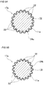
- a surface of the male spline part 11a may be provided with a coating layer 24a, 24b made of a low friction material for reducing an axial frictional resistance of the spline engaging portions with the female spline part 18, as shown in FIGS. 5A and 5B .
- the low friction material for configuring the coating layer 24a, 24b a variety of materials having required heat resistance and wear resistance can be used.
- a solid lubricant such as molybdenum disulfide may also be used, in addition to a synthetic resin such as polyamide resin (PA), polyphenylenesulfide resin (PPS) and polyacetal resin (POM).
- PA polyamide resin
- PPS polyphenylenesulfide resin
- POM polyacetal resin
- the coating layer 24a shown in FIG. 5A of the coating layers 24a, 24b is thickened at parts corresponding to bottoms of the respective spline groove portions 23, 23. Therefore, the female spline part 18 and the coating layer 24a are contacted or closely face each other over an entire surface at a state where the male spline part 11 a and the female spline part 18 are spline-engaged.
- the coating layer 24b shown in FIG. 5B is formed to be entirely thin, including parts corresponding to the bottoms of the respective spline groove portions 23, 23.
- the torque transmission shaft 17a having the universal joint yoke having the above configuration and manufactured as described above, it is possible to save the manufacturing cost of the torque transmission shaft 17a having the universal joint yoke and to easily reduce a weight of the torque transmission shaft 17a having the universal joint yoke.
- the outer periphery of one axial end portion is crushed diametrically inwards at the plurality of circumferential places, so that the plurality of spline groove portions 23, 23, each of which extends axially, are formed.
- the extra thicknesses extruded from the respective spline groove portions 23, 23 are bulged diametrically outwards between the circumferentially adjacent spline groove portions 23, 23, so that the plurality of spline teeth 22, 22, each of which extends axially, are formed.
- the male spline part 11a is made by the plastic working, the hardness and toughness of the respective spline teeth 22, 22 configuring the male spline part 11 a are not particularly lowered but are sufficiently increased by densification and work hardening of the metal material resulting from the plastic working.
- the tooth tip circle diameter of the male spline part 11 a is not made to be particularly large (even when the height of the respective spline teeth 22, 22 configuring the male spline part 11 a is made to be lower to some extent), it is possible to secure the sufficient strength of the spline engaging between the male spline part 11a and the female spline part 18 formed on the inner periphery of the other torque transmission shaft 8b, and to secure a capacity of the torque which can be transmitted by the intermediate shaft 5 including the torque transmission shaft 17a having the universal joint yoke.
- FIG. 8 illustrates the intermediate shaft 5 configured by combining a torque transmission shaft 17b having a universal joint yoke of this embodiment and the torque transmission shaft 8b.
- the torque transmission shaft 17b having the universal joint yoke of this embodiment is characterized in a structure of a coating layer 24c made of a low friction material and provided on the surface of the male spline part 11a. Since the other structures and manufacturing method are the same as those of the torque transmission shaft 17a having the universal joint yoke of the first embodiment, the structure of the coating layer 24c is focused in the below descriptions.
- the coating layer 24c is formed over the entire length and entire circumference of the male spline part 11 a.
- a thickness size W 25 of groove bottom layers 25, 25 of the coating layer 24c, which are formed on the groove bottom of the male spline part 11a, in the diametrical direction (a direction orthogonal to a groove bottom surface) is larger than a thickness size W 26 of tooth tip layers 26, 26 in the diametrical direction (a direction orthogonal to the tooth tip) formed on the tooth tip portions of the male spline part 11a (W 25 >W 26 ).
- an outer diameter size D 25 of each groove bottom layer 25, 25 is larger than an outer diameter size D 19 of the rod part 19 (D 25 >D 19 ). Also, as shown in FIGS. 8 and 9 , at the state where the intermediate shaft 5 is configured, a gap for collecting grease is formed between the outer periphery of each groove bottom layer 25, 25 and a tooth tip surface of the female spline tooth of the female spline part 18 configuring the torque transmission shaft 8b and between the outer periphery of each tooth tip layer 26, 26 and the groove bottom surface of the female spline part 18.
- each groove bottom layer 25, 25 is smaller than a tooth tip circle (an inscribed circle) diameter D 18a of the female spline part 18 (D 25 ⁇ D 18a ).
- an outer diameter size D 26 of each tooth tip layer 26, 26 is smaller than a groove bottom circle diameter D 18b of the female spline part 18 (D 24b ⁇ D 18b ).
- a part of the torque transmission shaft 17b having the universal joint yoke of this embodiment except for the coating layer 24c is made by the same manufacturing method as the first embodiment.
- the groove bottom diameter d 11 of the male spline part 11a is smaller than the outer diameter D 19 of the rod part 19 (d 11 ⁇ D 19 ), and the tooth tip diameter D 11 is larger than the outer diameter D 19 of the rod part 19 (d 11 ⁇ D 19 ⁇ D 11 ) due to the distinguishing manufacturing process.
- a space (gap) between the groove bottom surface of the male spline part 11 a and the tooth tip surface of the female spline part 18 is increased, as shown in FIG. 2 , for example.
- the space preferably has a certain level of size so as to collect the grease therein.
- a vibration suppression effect (damping effect) by the grease present in the space is deteriorated, so that the vibrations occurring at the axial expansion and contraction of the intermediate shaft 5 are transmitted to the steering wheel and the driver may feel uncomfortable.
- the thickness relation between the respective groove bottom layers 25, 25 of the coating layer 24c and the respective tooth tip layers 26, 26 is adjusted as described above. For this reason, it is possible to make the space small and to adjust the same to an appropriate size by the respective groove bottom layers 25, 25. As a result, it is possible to improve the vibration suppression effect (damping effect) by the grease filled in the space.
- the other structures, operations and effects are the same as the first embodiment.
- the present invention is not limited to the above embodiments and can be appropriately modified and/or improved.
- any plastic working capable of denting circumferential portions of one axial end portion of a rod-shaped element diametrically inwards to form spline groove portions, each of which extends axially, and projecting (bulging) portions between the circumferentially adjacent spline groove portions diametrically outwards to form spline teeth, each of which extends axially, can be applied.
- the press working, the forge processing, the rolling processing and the like can be adopted.
- one axial end portion of the rod-shaped element is compressed diametrically between a plurality of molds configured to be diametrically displaced (perspective movement).
- one axial end portion of the rod-shaped element is strongly axially pressed in a die, which is a type of a mold and has an inner surface shape conforming to (a concavo-convex shape is reverse to and the other basic shape coincides with) an outer surface shape of the male spline part.
- a die which is a type of a mold and has an inner surface shape conforming to (a concavo-convex shape is reverse to and the other basic shape coincides with) an outer surface shape of the male spline part.
- one axial end portion of the rod-shaped element is strongly sandwiched between a pair of rack-shaped press dies each of which is a mold and is formed on each of side surfaces thereof facing each other with teeth conforming to the outer surface shape of the male spline part.
- both press dies are reciprocally displaced in a direction along which the respective teeth are arranged.
- the shape of the teeth formed on both the press dies is transferred to the outer periphery of one axial end portion of the rod-shaped element, so that the male spline part is formed.
- the present invention is applied to the intermediate shaft which configures the automobile steering apparatus and is configured to transmit the rotation of the steering shaft to the input shaft of a steering gear unit.
- the present invention can also be applied to a variety of torque transmission shafts in which a cross shaft type universal joint is provided at an end portion and spline engaging portions are provided at an intermediate part.
- the engaging portions of the torque transmission shaft having the round rod shape and the torque transmission shaft having the round tube shape may also be made by serrations having a fine pitch, as shown in FIG. 10 .
Landscapes
- Engineering & Computer Science (AREA)
- Mechanical Engineering (AREA)
- General Engineering & Computer Science (AREA)
- Chemical & Material Sciences (AREA)
- Combustion & Propulsion (AREA)
- Transportation (AREA)
- Ocean & Marine Engineering (AREA)
- Steering Controls (AREA)
- Shafts, Cranks, Connecting Bars, And Related Bearings (AREA)
Abstract
Description
- The present invention relates to a torque transmission shaft having a universal joint yoke for configuring an intermediate shaft which configures, for example, an automobile steering apparatus and is configured to transmit rotation of a steering shaft to an input shaft of a steering gear unit, and relates to a method of manufacturing the same.
- A steering apparatus shown in
FIG. 11 , for example, has been conventionally used as an automobile steering apparatus. The steering apparatus is configured to convert rotational motion of a steering wheel 1 operated by a driver into linear motion at asteering gear unit 2, thereby applying a desired steering angle to left and right steering wheels (not shown). In order to implement this configuration, the steering wheel 1 is fixed to a rear end portion of asteering shaft 3. Also, a front end portion of thesteering shaft 3 is coupled to a base end portion of aninput shaft 6 of thesteering gear unit 2 through a pair ofuniversal joints intermediate shaft 5. Also, a pair oftie rods steering gear unit 2 and are respectively coupled to the left and right steering wheels, are coupled at base end portions thereof to both end portions of a rack shaft, which has rack teeth meshed with pinion teeth provided at an intermediate part of theinput shaft 6, through spherical joints. - In the steering apparatus configured as described above, when the driver operates the steering wheel 1, the rotation of the steering wheel 1 is transmitted to the
pinion shaft 6 through thesteering shaft 3, theuniversal joints intermediate shaft 5. As a result, the rack shaft is displaced in a shaft direction (a width direction of a vehicle body) and thetie rods - The
intermediate shaft 5 configuring the steering apparatus as described above is required to have not only a function of transmitting the torque between theuniversal joints - For the purpose of smoothly adjusting a position of the steering wheel 1 in a front-rear direction.
- An interval between the
universal joints intermediate shaft 5 so that an entire length thereof can be smoothly (with small force) expanded and contracted. - (2) For the purpose of protecting a body of the driver at collision accident.
- At collision accident, as an automobile primarily collides with another automobile and the like, the
steering gear unit 2 is strongly pushed rearwards. If the movement of thesteering unit 2 is transmitted to thesteering shaft 3, as it is, the steering wheel 1 supported and fixed to the rear end portion of thesteering shaft 3 is furiously displaced (pushed up) towards the body of the driver, so that it is difficult to protect the driver. Therefore, theintermediate shaft 5 is configured so that the entire length is contracted by shock load resulting from the primary collision. Thereby, the movement of thesteering gear unit 2 resulting from the primary collision is not transmitted, as it is, to thesteering shaft 3. Incidentally, in order to achieve this function, the load necessary to expand and contract theintermediate shaft 5 may be large to some extent. - The
intermediate shaft 5 configuring the steering apparatus is required to have the function of expanding and contracting the entire length thereof, in addition to the function of transmitting the torque, as described above. Theintermediate shaft 5 having those functions has been conventionally widely used (for example, refer to Patent Documents 1 and 2).FIGS. 12 ,13A and 13B illustrate an example of theintermediate shaft 5 conventionally widely used. Theintermediate shaft 5 has a pair oftorque transmission shafts yokes universal joints torque transmission shafts universal joints other yokes yokes cross shafts 10 so that the torque can be transmitted between therespective yokes yokes - A tip portion (a left end portion in
FIG. 12 ) of thetorque transmission shaft 8a having the round rod shape of thetorque transmission shafts intermediate shaft 5 is made to have a larger diameter than an intermediate part thereof and male spline teeth are formed on an outer periphery of the large diameter part, so that amale spline part 11 is provided on the outer periphery of the tip portion of thetorque transmission shaft 8a. In this conventional structure, a groove bottom diameter d11 of themale spline part 11 is made to be larger than an outer diameter D8a of the intermediate part of thetorque transmission shaft 8a (d11>D8a), so that the large diameter part can be formed with the male spline teeth by broach processing, which is a type of cutting processing. In contrast, an inner periphery of thetorque transmission shaft 8b having the round tube shape is formed with female spline teeth over a substantial entire length of the inner periphery of thetorque transmission shaft 8b, so that the substantial entire inner periphery of thetorque transmission shaft 8b is formed as afemale spline part 18. - As shown in
FIG. 12 , themale spline part 11 formed on the outer periphery of the tip portion of thetorque transmission shaft 8a having the round rod shape is engaged with thefemale spline part 18 provided on the inner periphery of thetorque transmission shaft 8b having the round tube shape, so that it is possible to obtain theintermediate shaft 5, of which an entire length can be expanded and contracted by thetorque transmission shaft 8a and thetorque transmission shaft 8b. In this case, when thespline parts intermediate shaft 5 is contracted, the shock energy input from the front end portion of theintermediate shaft 5 upon the collision accident can be absorbed). - Regarding the respective members of the
intermediate shaft 5 having theuniversal joints torque transmission shaft 8a having the round rod shape and theyoke 9 are integrally formed to obtain a torque transmission shaft having a universal joint yoke, it is not necessary to perform an operation of coupling and fixing thetorque transmission shaft 8a and theyoke 9 by welding and like and it is possible to increase the strength of the coupling part, which are advantageous to the saving of the cost of theintermediate shaft 5 and the improvement on the strength thereof.FIGS. 14A to 14C illustrate an example of a conventional method of manufacturing a torque transmission shaft having a universal joint yoke, in which thetorque transmission shaft 8a having the round rod shape and theyoke 9 are integrally formed. - According to the conventional manufacturing method, plastic working such as forge processing is performed for a hollow or solid metal material such as medium-carbon steel, so that a first intermediate material 12 as shown in
FIG. 14A is obtained. One axial half part (a part except for the other axial end portion, a left part ofFIGS. 14A to 14C ) of the first intermediate material 12 is formed as a firstbase rod part 13 having an outer diameter D13 which is constant over a substantial entire length, and a base end portion of theyoke 9 is fixed to the other axial end portion (a right end portion inFIGS. 14A to 14C ) of the firstbase rod part 13, so that the firstbase rod part 13 and theyoke 9 are integrally formed. The outer diameter D13 of the firstbase rod part 13 is larger than the outer diameter D8a of the intermediate part (the part axially distant from themale spline part 11 and the yoke 9) of the completedtorque transmission shaft 8a having the round rod shape shown inFIGS. 12 ,13A and 13B and is substantially the same as a tooth tip circle diameter (a circumscribed circle diameter) D11 of the male spline part 11 (D11≒D13>D8a). The cutting processing such as turning machining is performed for the other axial end portion (an axially intermediate part of the first intermediate material 12) of the firstbase rod part 13, so that a secondintermediate material 14 as shown inFIG. 14B is obtained. In the secondintermediate material 14, an outer diameter D15 of the other axial end portion (an axially intermediate part of the second intermediate material 14) of a secondbase rod part 15 provided at one axial half part thereof is made substantially the same as the outer diameter D8a (D15≒D8a) of the intermediate part of the completedtorque transmission shaft 8a having the round rod shape and one axial end portion is provided with alarge diameter part 16 having an outer diameter which is larger than the other axial end portion. Then, an outer periphery of thelarger diameter part 16 is formed with male spline teeth, so that the outer periphery of the corresponding part is provided with themale spline part 11. Thereby, atorque transmission shaft 17 having a universal joint yoke, in which thetorque transmission shaft 8a having the round rod shape and theyoke 9 are integrally formed, is obtained. - According to the
torque transmission shaft 17 having the universal joint yoke, it is not necessary to perform an operation of coupling and fixing thetorque transmission shaft 8a and theyoke 9 by the welding and like and it is possible to increase the strength of the coupling part, which are advantageous to the saving of the cost of theintermediate shaft 5 and the improvement on the strength thereof, like the conventional structure shown inFIG. 12 . However, it is necessary to perform the cutting processing such as turning machining for the other axial end portion of the firstbase rod part 13, so that the manufacturing cost of thetorque transmission shaft 17 having the universal joint yoke is increased. Also, the groove bottom diameter d11 of themale spline part 11 is increased beyond necessity, so that it is difficult to reduce a weight of the entireintermediate shaft 5 including thetorque transmission shaft 17 having the universal joint yoke. -
- Patent Document 1:
JP-A-2001-182736 - Patent Document 2:
JP-A-2012-117560 - It is therefore an object of the present invention to provide a torque transmission shaft having a universal joint yoke and a manufacturing method thereof with which it is possible to save a manufacturing cost and to easily reduce a weight thereof.
- A torque transmission shaft having a universal joint yoke according to the present invention includes: a rod part which has a round rod shape and includes a male spline part provided on an outer periphery of one axial end portion thereof; and a yoke which is fixed to another axial end portion of the rod part and includes a pair of arm parts configured to pivotally support end portions of a cross shaft configuring a cross shaft type universal joint, wherein a groove bottom diameter of the male spline part is smaller than an outer diameter of a part of the rod part axially distant from the male spline part.
- A surface of the male spline part may be provided with a coating layer made of a low friction material.
- In the coating layer, a groove bottom layer formed on a groove bottom of the male spline part may have a diametrical thickness larger than a diametrical thickness of a tooth tip layer formed on a tooth tip portion of the male spline part.
- A sectional shape of a spline groove of the male spline part may be a partial arc shape.
- There is provided a telescopic shaft including the above torque transmission shaft having the universal joint yoke, and another torque transmission shaft which has a round tube shape at least at the other axial end portion and includes a female spline part formed on an inner periphery of the other axial end portion and configured to be spline-engaged with the male spline part, so that the torque can be transmitted between the torque transmission shaft having the universal joint yoke and the other torque transmission shaft, and the torque transmission shaft having the universal joint yoke can be relatively moved with the other torque transmission shaft. A part of the rod part axially distant from the male spline part may have an outer diameter smaller than an inscribed circle diameter of the female spline part of the other torque transmission shaft
- A method of manufacturing a torque transmission shaft having a universal joint yoke according to the present invention, in order to manufacture the above torque transmission shaft having the universal joint yoke, includes providing a rod-shaped element to which the yoke is fixed at another axial end portion thereof, an outer diameter of an axial half part of the rod-shaped element being the same as an outer diameter of the finished rod part at a side of the axial end portion thereof (a part of the rod part axially distant from the male spline part); and performing plastic working for deforming an outer periphery of one axial end portion of the rod-shaped element, on the outer periphery of the one axial end portion, thereby forming the male spline part on the outer periphery of the one axial end portion of the rod-shaped element such that the male spline part has a groove bottom diameter smaller than an outer diameter of the rod part at a side of the other axial end portion thereof and has a tooth tip diameter larger than the outer diameter of the rod part at the side of the other axial end portion thereof.
- The plastic working may be forge processing of pressing a mold which has a processing surface of a shape conforming to an outer surface shape of the male spline part, to the outer periphery of the one axial end portion of the rod-shaped element.
- A sectional shape of a spline groove of the male spline part may be a partial arc shape.
- Incidentally, the term 'spline' described in the specification and the claims includes a general spline of which a circumferential pitch of teeth and grooves is larger, and also one referred to as serration of which a circumferential pitch of teeth is smaller.
- According to the torque transmission shaft having the universal joint yoke and the manufacturing method thereof as described above, it is possible to save the manufacturing cost and to easily reduce the weight thereof.
- That is, according to the present invention, in order to form the male spline part on the outer periphery of one axial end portion of the rod-shaped element, one axial end portion is crushed diametrically inwards at the plurality of circumferential places, so that the plurality of spline groove portions, each of which extends axially, are formed. At the same time, the extra thicknesses extruded from the respective spline groove portions are projected (uphove) diametrically outwards between the circumferentially adjacent spline groove portions, so that the plurality of spline teeth, each of which extends axially, are formed between the respective spline groove portions. Therefore, it is not necessary to perform cutting processing such as turning machining for a part of the rod-shaped element becoming the rod part, so as to prevent the interference between tip portions of the spline teeth configuring the female spline part formed on the inner periphery of the other torque transmission shaft having the round tube shape and the outer periphery of the rod part of the torque transmission shaft having the universal joint yoke. For this reason, it is possible to save the manufacturing cost of the torque transmission shaft having the universal joint yoke. Also, since the male spline part is made by the plastic working, the hardness of the spline teeth configuring the male spline part is sufficiently increased by densification and work hardening of the metal material resulting from the plastic working. Therefore, even when the tooth tip circle diameter of the male spline part is not made to be particularly larger (even when a height of the spline teeth configuring the male spline part is made to be lower to some extent), it is possible to secure the sufficient strength of the spline engaging between the male spline part and the female spline part formed on the inner periphery of the other torque transmission shaft (it is possible to secure a capacity of the torque which can be transmitted by the torque transmission shaft having the universal joint yoke). For this reason, it is not necessary to enlarge the pitch circle diameter of the spline engaging portions of the male and female spline parts and the outer diameter (the groove bottom diameter and the tooth tip circle diameter) of the part, for which the spline engaging portions are provided, of the torque transmission shaft having the universal joint yoke, beyond necessity, so that it is easy to reduce weights of the torque transmission shaft having the universal joint yoke and a telescopic shaft such as the intermediate shaft including the torque transmission shaft having the universal joint yoke.
-
-
FIG. 1 is a side view of a torque transmission shaft having a universal joint yoke according to a first embodiment of the present invention. -
FIG. 2A is an end view illustrating a torque transmission shaft having the universal joint yoke, as seen from a left side ofFIG. 1 , andFIG. 2B is a sectional view illustrating a state where the torque transmission shaft having the universal joint yoke and another torque transmission shaft having a round tube shape are combined. -
FIGS. 3A and 3B are partial side views illustrating a process of providing one axial end portion of a rod part with a male spline part so as to make the torque transmission shaft having the universal joint yoke, andFIG. 3C is a partial sectional view illustrating a state where the male spline part is combined with a female spline part of the other torque transmission shaft. -
FIGS. 4A and 4B are side views illustrating the entire torque transmission shaft having the universal joint yoke at the same states asFIGS. 3A and 3B . -
FIGS. 5A and 5B are enlarged sectional views taken along a V-V line ofFIG. 1 , which illustrate two examples of a structure where a coating layer made of a low friction material is provided for the male spline part. -
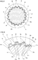
FIG. 6 is an enlarged sectional view corresponding to a VI part ofFIG. 2B , which illustrates a relation between spline teeth configuring both male and female spline parts and a pitch circle diameter of spline engaging portions. -
FIG. 7 is the same view asFIG. 6 , which illustrates another shape of the spline teeth configuring the male spline part. -
FIG. 8 is the same view asFIG. 2B , which illustrates a second embodiment of the present invention. -
FIG. 9 is the same view asFIG. 6 , which illustrates the second embodiment of the present invention. -
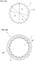
FIG. 10 is a view corresponding to the enlarged V-V sectional view ofFIG. 1 , which illustrates a sectional shape of a male serration, which is a type of the male spline part. -
FIG. 11 is a partially cut side view illustrating one example of an automobile steering apparatus, in which an intermediate shaft including a torque transmission shaft having a universal joint yoke which is a subject of the present invention is incorporated. -
FIG. 12 is a cut side view illustrating the intermediate shaft. -
FIG. 13A is an end view illustrating a torque transmission shaft having a round rod shape, as seen from a left side ofFIG. 12 , andFIG. 13B is a sectional view illustrating a state where the torque transmission shaft is combined with another torque transmission shaft having a round tube shape. -
FIGS. 14A to 14C are side views illustrating processes of manufacturing a conventional torque transmission shaft having a universal joint yoke. - A first embodiment of the present invention will be described with reference to
FIGS. 1 to 7 .FIG. 1 illustrates a completedtorque transmission shaft 17a having a universal joint yoke according to this embodiment. Thetorque transmission shaft 17a having the universal joint yoke is provided on an outer periphery of one axial end portion (a left end portion inFIG. 1 ) of arod part 19 having a circular section with amale spline part 11a, and a base end portion of ayoke 9 having a pair ofarm parts FIG. 12 ) configuring the cross shaft-typeuniversal joint 4a is fixed to the other axial end portion (a right end portion inFIG .1 ) of therod part 19. In particular, in the case of thetorque transmission shaft 17a having the universal joint yoke of this embodiment, a groove bottom diameter d11 of themale spline part 11a is made to be smaller than an outer diameter D19 of the other axial end side part (a part of therod part 19 axially distant from themale spline part 11a) of the rod part 19 (d11<D19). As shown inFIGS. 2B and3C , themale spline part 11a of thetorque transmission shaft 17a having the universal joint yoke is spline-engaged with afemale spline part 18 provided on an inner periphery of the othertorque transmission shaft 8b having a round tube shape. Thereby, the torque can be transmitted between the torque transmission shaft having the universal joint yoke and the othertorque transmission shaft 8b, and the intermediate shaft (refer toFIGS. 11 to 13 ) of which axial size can be expanded and contracted is configured. - As shown in
FIGS. 3A, 3B ,4A and 4B , thetorque transmission shaft 17a having the universal joint yoke as described above is made by performing only plastic working for a hollow or solid rod-shaped metal material, in principle. That is, even though cutting processing and grinding processing may be performed for finishing, the cutting processing and grinding processing causing a shape and a size to be changed are not performed in principle, except for a chamfering of an end portion, for example. In this embodiment, in order to make thetorque transmission shaft 17a having the universal joint yoke as described above, a rod-shapedelement 21 as shown inFIGS. 3A and4A is first made by performing the plastic working such as press working and forge processing for a metal material such as carbon steel and stainless steel. The base end portion of theyoke 9 is fixed to the other axial end portion of the rod-shapedelement 21 and an outer diameter D21 of one axial half part (a part except for the other axial end portion) thereof is made to be the same as an outer diameter D19 of the completed rod part 19 (D21=D19). The plastic working for making the rod-shapedelement 21 is the same as the plastic working for making the first intermediate material 12, except that the outer diameter D21 of the rod-shapedelement 21 is made to be smaller than the outer diameter D13 of the firstbase rod part 13 of the conventional first intermediate material 12 shown inFIG. 14A and to be substantially the same as the outer diameter D8a of the intermediate part of the completedtorque transmission shaft 8a shown inFIG. 14C (D13>D21≒D8a). Also, since the well-known method can be applied to a method of implementing the plastic working for making the rod-shapedelement 21, the specific illustration and description thereof will be omitted. - After the rod-shaped
element 21 as described above is made, the plastic working for diametrically deforming an outer periphery of one axial end portion of the rod-shapedelement 21 is performed for the outer periphery of one axial end portion, as shown inFIGS. 3A and 3B , so that themale spline part 11a is formed on the outer periphery of one axial end portion. As described above, themale spline part 11a is formed to have the groove bottom diameter d11 smaller than the outer diameter D19 of the rod part 19 (d11<D19) and to have a tooth tip diameter D11 larger than the outer diameter D19 of the rod part 19 (d11<D19<D11). Also, the groove bottom diameter d11 and the outer diameter D19 of therod part 19 are smaller than a tooth tip circle diameter (an inscribed circle diameter) D18 of thefemale spline part 18 formed on the inner periphery of the othertorque transmission shaft 8b having the round tube shape (d11<D19<D18). Therefore, as described later, there is no interference between tooth tips ofrespective spline teeth rod part 19 and the groove bottoms of themale spline part 11a or outer periphery of therod part 19 at a state where themale spline part 11a and thefemale spline part 18 are spline-engaged. - Incidentally, during the plastic working for forming the
male spline part 11a, the outer periphery of one axial end portion of the rod-shapedelement 21 is crushed diametrically inwards at a plurality of circumferential places, so that a plurality ofspline groove portions spline groove portions spline groove portions spline teeth spline groove portions spline groove portions spline teeth - Regarding the plastic working, the forge processing, particularly, the cold forge processing is most preferable because it is possible to obtain the high size precision and shape precision and the
male spline part 11a of high strength. When forming themale spline part 11 a on the outer periphery of one axial end portion of the rod-shapedelement 21 by the forge processing, one axial end portion of the rod-shapedelement 21 is strongly axially pressed in a die, which is a type of a mold and has an inner surface shape conforming to (a concavo-convex shape is reverse to and the other basic shape coincides with) an outer surface shape of themale spline part 11a, the outer periphery of one axial end portion of the rod-shapedelement 21 is pressed diametrically inwards over the axial direction at a plurality of circumferential places (actually, the diametrically outward bulging is suppressed) to form the respectivespline groove portions spline groove portions - The
torque transmission shaft 17a having the universal joint yoke, in which themale spline part 11 a is integrally provided on the outer periphery of one axial end portion and theyoke 9 is integrally provided at the other axial end portion as described above, is spline-engaged at themale spline part 11 a with thefemale spline part 18 formed on the inner periphery of the othertorque transmission shaft 8b having the round tube shape, as shown inFIGS. 3C and2B , so that the torque can be transmitted between thetorque transmission shaft 17a and the othertorque transmission shaft 8b and theintermediate shaft 5 of which axial size can be expanded and contracted is configured, as shown inFIGS. 11 and12 . At this state, the tooth tips of therespective spline teeth male spline part 11 a are positioned at a diametrical outer side of a pitch circle P and the tooth tips of therespective spline teeth female spline part 18 are positioned at a diametrical inner side of the pitch circle P, as shown inFIG. 6 . For example, therespective spline teeth spline parts intermediate shaft 5. Incidentally, when a sectional shape of thespline groove portions respective spline teeth male spline part 11 a is formed to have a partial arc shape, as shown inFIG. 7 , the stiffness of thespline teeth spline groove portions intermediate shaft 5. - Incidentally, the spline engaging state (axial engaging strength) between the
male spline part 11a and thefemale spline part 18 is appropriately adjusted by performance required for theintermediate shaft 5. In order to enable the spline parts to be axially displaced with small force so that theintermediate shaft 5 can smoothly adjust a position of a steering wheel in a front-rear direction, for example, a surface of themale spline part 11a may be provided with acoating layer female spline part 18, as shown inFIGS. 5A and 5B . As the low friction material for configuring thecoating layer - The
coating layer 24a shown inFIG. 5A of thecoating layers spline groove portions female spline part 18 and thecoating layer 24a are contacted or closely face each other over an entire surface at a state where themale spline part 11 a and thefemale spline part 18 are spline-engaged. In contrast, thecoating layer 24b shown inFIG. 5B is formed to be entirely thin, including parts corresponding to the bottoms of the respectivespline groove portions male spline part 11a and thefemale spline part 18 are spline-engaged, there is a gap between the tooth tip portions of thefemale spline part 18 and thecoating layer 24b. In the gap, grease for lubricating the spline engaging portions between themale spline part 11a and thefemale spline part 18 may be collected, so that the lubricating state of the spline engaging portions by the grease can be favorably maintained for a long time. - According to the
torque transmission shaft 17a having the universal joint yoke having the above configuration and manufactured as described above, it is possible to save the manufacturing cost of thetorque transmission shaft 17a having the universal joint yoke and to easily reduce a weight of thetorque transmission shaft 17a having the universal joint yoke. - That is, according to the manufacturing method of this embodiment, in order to form the
male spline part 11a on the outer periphery of one axial end portion of the rod-shapedelement 21, the outer periphery of one axial end portion is crushed diametrically inwards at the plurality of circumferential places, so that the plurality ofspline groove portions spline groove portions spline groove portions spline teeth element 21, which is a base rod part becoming therod part 19, so as to prevent the interference between the tip portions of thespline teeth female spline part 18 formed on the inner periphery of the othertorque transmission shaft 8b having the round tube shape and the outer periphery of therod part 19 of thetorque transmission shaft 17a having a universal joint yoke. For this reason, it is possible to save the manufacturing cost of thetorque transmission shaft 17a having the universal joint yoke. - Also, since the
male spline part 11a is made by the plastic working, the hardness and toughness of therespective spline teeth male spline part 11 a are not particularly lowered but are sufficiently increased by densification and work hardening of the metal material resulting from the plastic working. Therefore, even when the tooth tip circle diameter of themale spline part 11 a is not made to be particularly large (even when the height of therespective spline teeth male spline part 11 a is made to be lower to some extent), it is possible to secure the sufficient strength of the spline engaging between themale spline part 11a and thefemale spline part 18 formed on the inner periphery of the othertorque transmission shaft 8b, and to secure a capacity of the torque which can be transmitted by theintermediate shaft 5 including thetorque transmission shaft 17a having the universal joint yoke. For this reason, it is not necessary to enlarge the pitch circle diameter of the spline engaging portions of the male andfemale spline parts torque transmission shaft 17a having a universal joint yoke, beyond necessity, so that it is easy to reduce weights of thetorque transmission shaft 17a having the universal joint yoke and theintermediate shaft 5 including thetorque transmission shaft 17a having the universal joint yoke. - A second embodiment of the present invention is described with reference to
FIGS. 8 and 9. FIG. 8 illustrates theintermediate shaft 5 configured by combining atorque transmission shaft 17b having a universal joint yoke of this embodiment and thetorque transmission shaft 8b. Incidentally, thetorque transmission shaft 17b having the universal joint yoke of this embodiment is characterized in a structure of acoating layer 24c made of a low friction material and provided on the surface of themale spline part 11a. Since the other structures and manufacturing method are the same as those of thetorque transmission shaft 17a having the universal joint yoke of the first embodiment, the structure of thecoating layer 24c is focused in the below descriptions. - In this embodiment, the
coating layer 24c is formed over the entire length and entire circumference of themale spline part 11 a. A thickness size W25 of groove bottom layers 25, 25 of thecoating layer 24c, which are formed on the groove bottom of themale spline part 11a, in the diametrical direction (a direction orthogonal to a groove bottom surface) is larger than a thickness size W26 of tooth tip layers 26, 26 in the diametrical direction (a direction orthogonal to the tooth tip) formed on the tooth tip portions of themale spline part 11a (W25>W26). Specifically, the thickness size W25 of eachgroove bottom layer tooth tip layer 26, 26 (W25 = (2 to 3) x W26). Incidentally, a thickness size W27 of aside surface layer 27 of thecoating layer 24c, which is formed on a circumferential side surface of each spline tooth of themale spline part 11a, in a direction orthogonal to the circumferential side surface is the same as the thickness size W26 of eachtooth tip layer 26, 26 (W27=W26). - Also, an outer diameter size D25 of each
groove bottom layer FIGS. 8 and 9 , at the state where theintermediate shaft 5 is configured, a gap for collecting grease is formed between the outer periphery of eachgroove bottom layer female spline part 18 configuring thetorque transmission shaft 8b and between the outer periphery of eachtooth tip layer female spline part 18. That is, the outer diameter size D25 of eachgroove bottom layer tooth tip layer - A part of the
torque transmission shaft 17b having the universal joint yoke of this embodiment except for thecoating layer 24c is made by the same manufacturing method as the first embodiment. According to thetorque transmission shaft 17b having the universal joint yoke made by the manufacturing method of the present invention, the groove bottom diameter d11 of themale spline part 11a is smaller than the outer diameter D19 of the rod part 19 (d11<D19), and the tooth tip diameter D11 is larger than the outer diameter D19 of the rod part 19 (d11<D19<D11) due to the distinguishing manufacturing process. Therefore, at a state where thecoating layer 24c is not provided, a space (gap) between the groove bottom surface of themale spline part 11 a and the tooth tip surface of thefemale spline part 18 is increased, as shown inFIG. 2 , for example. The space preferably has a certain level of size so as to collect the grease therein. However, if the space is excessively large, a vibration suppression effect (damping effect) by the grease present in the space is deteriorated, so that the vibrations occurring at the axial expansion and contraction of theintermediate shaft 5 are transmitted to the steering wheel and the driver may feel uncomfortable. - However, in this embodiment, the thickness relation between the respective groove bottom layers 25, 25 of the
coating layer 24c and the respective tooth tip layers 26, 26 is adjusted as described above. For this reason, it is possible to make the space small and to adjust the same to an appropriate size by the respective groove bottom layers 25, 25. As a result, it is possible to improve the vibration suppression effect (damping effect) by the grease filled in the space. The other structures, operations and effects are the same as the first embodiment. - In the meantime, the present invention is not limited to the above embodiments and can be appropriately modified and/or improved.
- For example, regarding the plastic working for forming the male spline part of the present invention, any plastic working capable of denting circumferential portions of one axial end portion of a rod-shaped element diametrically inwards to form spline groove portions, each of which extends axially, and projecting (bulging) portions between the circumferentially adjacent spline groove portions diametrically outwards to form spline teeth, each of which extends axially, can be applied. For example, the press working, the forge processing, the rolling processing and the like can be adopted. According to the press working, one axial end portion of the rod-shaped element is compressed diametrically between a plurality of molds configured to be diametrically displaced (perspective movement). Thereby, a concavo-convex shape formed on an inner periphery, which is a processing surface of each mold, is transferred to an outer periphery of one axial end portion of the rod-shaped element, so that the male spline part is formed.
- Also, according to the forge processing, one axial end portion of the rod-shaped element is strongly axially pressed in a die, which is a type of a mold and has an inner surface shape conforming to (a concavo-convex shape is reverse to and the other basic shape coincides with) an outer surface shape of the male spline part. Thereby, one axial end portion of the rod-shaped element is bulged diametrically outwards to make the outer surface shape of one axial end portion coincide with the inner surface shape of the die.
- Also, according to the rolling processing, one axial end portion of the rod-shaped element is strongly sandwiched between a pair of rack-shaped press dies each of which is a mold and is formed on each of side surfaces thereof facing each other with teeth conforming to the outer surface shape of the male spline part. At this state, both press dies are reciprocally displaced in a direction along which the respective teeth are arranged. Thereby, the shape of the teeth formed on both the press dies is transferred to the outer periphery of one axial end portion of the rod-shaped element, so that the male spline part is formed.
- The present application is based on
Japanese Patent Application No. 2013-157518 filed on July 30, 2013 Japanese Patent Application No. 2014-050230 filed on March 13, 2014 - In the above descriptions, the present invention is applied to the intermediate shaft which configures the automobile steering apparatus and is configured to transmit the rotation of the steering shaft to the input shaft of a steering gear unit. However, the present invention can also be applied to a variety of torque transmission shafts in which a cross shaft type universal joint is provided at an end portion and spline engaging portions are provided at an intermediate part. Also, when the torque to be transmitted is not so high, the engaging portions of the torque transmission shaft having the round rod shape and the torque transmission shaft having the round tube shape may also be made by serrations having a fine pitch, as shown in
FIG. 10 . -
- 1:
- steering wheel
- 2:
- steering gear unit
- 3:
- steering shaft
- 4a, 4b:
- universal joint
- 5:
- intermediate shaft
- 6:
- input shaft
- 7:
- tie rod
- 8a, 8b:
- torque transmission shaft
- 9, 9a, 9b:
- yoke
- 10:
- cross shaft
- 11, 11a:
- mail spline part
- 12:
- first intermediate material
- 13:
- first base rod part
- 14:
- second intermediate material
- 15:
- second base rod part
- 16:
- large diameter part
- 17a, 17b:
- torque transmission shaft having a universal joint yoke
- 18:
- female spline part
- 19:
- rod part
- 20:
- arm part
- 21:
- rod-shaped element
- 22, 22a:
- spline tooth
- 23, 23a:
- spline groove portion
- 24a, 24b:
- coating layer
- 25:
- groove bottom layer
- 26:
- tooth tip layer
- 27:
- side surface layer
Claims (8)
- A torque transmission shaft having a universal joint yoke, the torque transmission shaft comprising:a rod part which has a round rod shape and includes a male spline part provided on an outer periphery of one axial end portion thereof; anda yoke which is fixed to another axial end portion of the rod part and includes a pair of arm parts configured to pivotally support end portions of a cross shaft configuring a cross shaft type universal joint,wherein a groove bottom diameter of the male spline part is smaller than an outer diameter of a part of the rod part axially distant from the male spline part.
- The torque transmission shaft having the universal joint yoke according to claim 1,
wherein a surface of the male spline part is provided with a coating layer made of a low friction material. - The torque transmission shaft having the universal joint yoke according to claim 2,
wherein in the coating layer, a groove bottom layer formed on a groove bottom of the male spline part has a diametrical thickness larger than a diametrical thickness of a tooth tip layer formed on a tooth tip portion of the male spline part. - The torque transmission shaft having the universal joint yoke according to claim 1,
wherein a sectional shape of a spline groove of the male spline part is a partial arc shape. - A telescopic shaft comprising:the torque transmission shaft having the universal joint yoke according to any one of claims 1 to 4, andanother torque transmission shaft which has a round tube shape at least at the other axial end portion and includes a female spline part formed on an inner periphery of the other axial end portion and configured to be spline-engaged with the male spline part,wherein a part of the rod part axially distant from the male spline part has an outer diameter smaller than an inscribed circle diameter of the female spline part of the other torque transmission shaft.
- A method of manufacturing a torque transmission shaft having a universal joint yoke, the torque transmission shaft including: a rod part which has a round rod shape and includes a male spline part provided on an outer periphery of one axial end portion thereof; and a yoke which is fixed to another axial end portion of the rod part and includes a pair of arm parts configured to pivotally support end portions of a cross shaft configuring a cross shaft type universal joint, the method comprising:providing a rod-shaped element to which the yoke is fixed at another axial end portion thereof, an outer diameter of an axial half part of the rod-shaped element being the same as an outer diameter of the finished rod part at a side of the other axial end portion thereof; andperforming plastic working for deforming an outer periphery of one axial end portion of the rod-shaped element, on the outer periphery of the one axial end portion, thereby forming the male spline part on the outer periphery of the one axial end portion of the rod-shaped element such that the male spline part has a groove bottom diameter smaller than an outer diameter of the rod part at the side of the other axial end portion thereof and has a tooth tip diameter larger than the outer diameter of the rod part at the side of the other axial end portion thereof.
- The method of manufacturing the torque transmission shaft having the universal joint yoke according to claim 6,
wherein the plastic working is forge processing of pressing a mold which has a processing surface of a shape conforming to an outer surface shape of the male spline part, to the outer periphery of the one axial end portion of the rod-shaped element. - The method of manufacturing the torque transmission shaft having the universal joint yoke according to claim 6,
wherein a sectional shape of a spline groove of the male spline part is a partial arc shape.
Applications Claiming Priority (3)
| Application Number | Priority Date | Filing Date | Title |
|---|---|---|---|
| JP2013157518 | 2013-07-30 | ||
| JP2014050230 | 2014-03-13 | ||
| PCT/JP2014/066579 WO2015015952A1 (en) | 2013-07-30 | 2014-06-23 | Torque transmission shaft with yoke for universal joint and manufacturing method therefor |
Publications (3)
| Publication Number | Publication Date |
|---|---|
| EP3001060A1 true EP3001060A1 (en) | 2016-03-30 |
| EP3001060A4 EP3001060A4 (en) | 2016-04-27 |
| EP3001060B1 EP3001060B1 (en) | 2019-01-30 |
Family
ID=52431494
Family Applications (1)
| Application Number | Title | Priority Date | Filing Date |
|---|---|---|---|
| EP14832831.3A Ceased EP3001060B1 (en) | 2013-07-30 | 2014-06-23 | Torque transmission shaft with yoke for universal joint and manufacturing method therefor |
Country Status (5)
| Country | Link |
|---|---|
| US (1) | US9915291B2 (en) |
| EP (1) | EP3001060B1 (en) |
| JP (1) | JP6354761B2 (en) |
| CN (1) | CN105473882B (en) |
| WO (1) | WO2015015952A1 (en) |
Cited By (1)
| Publication number | Priority date | Publication date | Assignee | Title |
|---|---|---|---|---|
| KR20220037248A (en) * | 2020-09-17 | 2022-03-24 | 두산중공업 주식회사 | Segment control device, turbine including the same |
Families Citing this family (15)
| Publication number | Priority date | Publication date | Assignee | Title |
|---|---|---|---|---|
| JP6292439B2 (en) * | 2013-12-17 | 2018-03-14 | 株式会社ジェイテクト | Spline telescopic shaft for steering and steering device |
| USD785082S1 (en) * | 2015-01-16 | 2017-04-25 | S-Printing Solution Co., Ltd. | Toner cartridge |
| JP6528848B2 (en) * | 2015-08-20 | 2019-06-12 | 日本精工株式会社 | Yoke integrated shaft and telescopic shaft |
| JP6657896B2 (en) * | 2015-12-10 | 2020-03-04 | 日本精工株式会社 | Method of manufacturing male shaft for telescopic shaft |
| JP6572806B2 (en) * | 2016-03-11 | 2019-09-11 | 日本精工株式会社 | Steering device shaft, steering device shaft manufacturing method, and electric power steering device |
| KR101930335B1 (en) * | 2016-10-11 | 2018-12-19 | 이양화 | Universal joint manufacturing method using the pipe |
| US11541450B2 (en) * | 2017-03-27 | 2023-01-03 | Nsk Ltd. | Shaft for steering device, method of manufacturing shaft for steering device, and electric power steering device |
| AT520015B1 (en) * | 2017-05-30 | 2019-02-15 | Miba Sinter Austria Gmbh | Assembly with a spline |
| JP7024329B2 (en) * | 2017-11-02 | 2022-02-24 | 日本精工株式会社 | Steering device |
| FR3081756A1 (en) * | 2018-05-31 | 2019-12-06 | Albea Services | METHOD FOR MANUFACTURING A PUMP GUIDE ROD |
| WO2020105582A1 (en) * | 2018-11-22 | 2020-05-28 | 日本精工株式会社 | Torque transmission shaft |
| CN111900826B (en) * | 2020-08-06 | 2022-07-15 | 珠海格力电器股份有限公司 | Motor with telescopic shaft |
| WO2022050306A1 (en) * | 2020-09-02 | 2022-03-10 | 日本精工株式会社 | Steering shaft and method for manufacturing steering shaft |
| BE1031796B1 (en) * | 2023-07-12 | 2025-02-12 | Thyssenkrupp Presta Ag | steering system for a motor vehicle |
| FR3153370A1 (en) * | 2023-09-22 | 2025-03-28 | Safran Aircraft Engines | ROTATING PART FOR AIRCRAFT TURBOMACHINE |
Family Cites Families (14)
| Publication number | Priority date | Publication date | Assignee | Title |
|---|---|---|---|---|
| USRE27068E (en) * | 1970-01-26 | 1971-02-23 | Slip spline assembly | |
| DE69531225T2 (en) * | 1994-10-13 | 2004-06-03 | Matsui Universal Joint Mfg. Co. | Manufacturing process for a drive shaft |
| US5836823A (en) * | 1996-02-28 | 1998-11-17 | Dana Corporation | Webbed yoke for universal joint |
| JP2001182736A (en) | 1999-12-24 | 2001-07-06 | Koyo Seiko Co Ltd | Freely extendable shaft |
| WO2004113150A1 (en) * | 2003-06-20 | 2004-12-29 | Nsk Ltd. | Motor vehicle steering device |
| CA2567755C (en) | 2004-06-14 | 2010-03-09 | Ernst Grob Ag | Grooved profile for a hub shaft connection |
| WO2008057060A2 (en) * | 2006-11-06 | 2008-05-15 | Tirsan Kardan Sanayi Ve Ticaret Anonim Sirketi | Sliding group of cardan shaft with interlocking mechanism |
| JP4995028B2 (en) * | 2007-10-15 | 2012-08-08 | Ntn株式会社 | Spline, spline connection structure, power transmission shaft and constant velocity universal joint |
| JP5120229B2 (en) | 2008-11-25 | 2013-01-16 | 日本精工株式会社 | Telescopic shaft manufacturing method and telescopic shaft manufactured by this manufacturing method |
| JP2011085152A (en) | 2009-10-13 | 2011-04-28 | Ntn Corp | Power transmission shaft, and assembly |
| JP5410265B2 (en) | 2009-12-21 | 2014-02-05 | Ntn株式会社 | Wheel bearing device |
| JP2011241957A (en) * | 2010-05-21 | 2011-12-01 | Mitsubishi Agricultural Machinery Co Ltd | Transmission structure of working vehicle |
| JP5582987B2 (en) | 2010-11-29 | 2014-09-03 | 株式会社ジェイテクト | Extendable shaft, method of manufacturing the same, and vehicle steering device |
| JP5915772B2 (en) * | 2013-05-27 | 2016-05-11 | 日本精工株式会社 | Inner shaft for telescopic shaft and manufacturing method thereof |
-
2014
- 2014-06-23 EP EP14832831.3A patent/EP3001060B1/en not_active Ceased
- 2014-06-23 CN CN201480042285.3A patent/CN105473882B/en active Active
- 2014-06-23 US US14/900,845 patent/US9915291B2/en active Active
- 2014-06-23 JP JP2015529457A patent/JP6354761B2/en not_active Expired - Fee Related
- 2014-06-23 WO PCT/JP2014/066579 patent/WO2015015952A1/en not_active Ceased
Cited By (1)
| Publication number | Priority date | Publication date | Assignee | Title |
|---|---|---|---|---|
| KR20220037248A (en) * | 2020-09-17 | 2022-03-24 | 두산중공업 주식회사 | Segment control device, turbine including the same |
Also Published As
| Publication number | Publication date |
|---|---|
| EP3001060A4 (en) | 2016-04-27 |
| EP3001060B1 (en) | 2019-01-30 |
| US20160153499A1 (en) | 2016-06-02 |
| CN105473882A (en) | 2016-04-06 |
| JPWO2015015952A1 (en) | 2017-03-02 |
| CN105473882B (en) | 2018-10-12 |
| WO2015015952A1 (en) | 2015-02-05 |
| JP6354761B2 (en) | 2018-07-11 |
| US9915291B2 (en) | 2018-03-13 |
Similar Documents
| Publication | Publication Date | Title |
|---|---|---|
| EP3001060B1 (en) | Torque transmission shaft with yoke for universal joint and manufacturing method therefor | |
| EP3006305B1 (en) | Inner shaft for telescopic shaft and production method thereof | |
| JP5447694B2 (en) | Telescopic shaft for steering device | |
| JP6597010B2 (en) | Method for manufacturing telescopic shaft | |
| US20140080614A1 (en) | Rotation transmitting apparatus, vehicle steering system, and intermediate shaft | |
| CN109477527B (en) | Telescopic shaft | |
| JP2012122610A (en) | Method of manufacturing telescopic shaft, and telescopic shaft manufactured by the method | |
| JP2002172430A (en) | Method and apparatus for manufacturing cylindrical member and cylindrical member having spline | |
| US20190388947A1 (en) | Hollow Torque Transmission Member and Manufacturing Method Thereof, Intermediate Shaft, and Steering Apparatus for Automobile | |
| JP2008213756A (en) | Steering device for automobile and method for manufacturing rack for steering device for automobile | |
| CN109562777B (en) | Method for manufacturing adjustable-length steering shaft and adjustable-length steering shaft | |
| JP6005402B2 (en) | Method for manufacturing outer joint member of constant velocity universal joint | |
| EP2738408B1 (en) | Cruciform-shaft universal joint and method for producing same | |
| JP6471803B2 (en) | Telescopic rotation transmission shaft and manufacturing method thereof | |
| US20220363304A1 (en) | Outer tube with hole cover | |
| JP6897184B2 (en) | Outer tube and its manufacturing method | |
| JP6601004B2 (en) | Method for manufacturing telescopic shaft | |
| JP7024329B2 (en) | Steering device | |
| JP2006207639A (en) | Manufacturing method of female spline shaft provided with oil sump, and female spline shaft manufactured by this manufacturing method | |
| JP5169750B2 (en) | Telescopic rotation transmission shaft | |
| JP2017003055A5 (en) | ||
| JP7322617B2 (en) | Manufacturing method of outer tube for steering intermediate shaft | |
| JP2020131278A (en) | Outer shaft and its manufacturing method | |
| JP6657896B2 (en) | Method of manufacturing male shaft for telescopic shaft | |
| JP2017106565A (en) | Telescopic shaft |
Legal Events
| Date | Code | Title | Description |
|---|---|---|---|
| PUAI | Public reference made under article 153(3) epc to a published international application that has entered the european phase |
Free format text: ORIGINAL CODE: 0009012 |
|
| 17P | Request for examination filed |
Effective date: 20151223 |
|
| AK | Designated contracting states |
Kind code of ref document: A1 Designated state(s): AL AT BE BG CH CY CZ DE DK EE ES FI FR GB GR HR HU IE IS IT LI LT LU LV MC MK MT NL NO PL PT RO RS SE SI SK SM TR |
|
| AX | Request for extension of the european patent |
Extension state: BA ME |
|
| A4 | Supplementary search report drawn up and despatched |
Effective date: 20160329 |
|
| RIC1 | Information provided on ipc code assigned before grant |
Ipc: B62D 1/185 20060101ALI20160321BHEP Ipc: F16D 1/02 20060101ALI20160321BHEP Ipc: F16C 3/02 20060101ALI20160321BHEP Ipc: F16D 1/06 20060101ALI20160321BHEP Ipc: B62D 1/19 20060101ALI20160321BHEP Ipc: F16D 3/06 20060101AFI20160321BHEP |
|
| DAX | Request for extension of the european patent (deleted) | ||
| 17Q | First examination report despatched |
Effective date: 20170810 |
|
| GRAP | Despatch of communication of intention to grant a patent |
Free format text: ORIGINAL CODE: EPIDOSNIGR1 |
|
| INTG | Intention to grant announced |
Effective date: 20180912 |
|
| GRAS | Grant fee paid |
Free format text: ORIGINAL CODE: EPIDOSNIGR3 |
|
| GRAA | (expected) grant |
Free format text: ORIGINAL CODE: 0009210 |
|
| RBV | Designated contracting states (corrected) |
Designated state(s): DE FR GB |
|
| AK | Designated contracting states |
Kind code of ref document: B1 Designated state(s): DE FR GB |
|
| REG | Reference to a national code |
Ref country code: GB Ref legal event code: FG4D |
|
| REG | Reference to a national code |
Ref country code: DE Ref legal event code: R096 Ref document number: 602014040516 Country of ref document: DE |
|
| PGFP | Annual fee paid to national office [announced via postgrant information from national office to epo] |
Ref country code: FR Payment date: 20190510 Year of fee payment: 6 |
|
| PGFP | Annual fee paid to national office [announced via postgrant information from national office to epo] |
Ref country code: GB Payment date: 20190619 Year of fee payment: 6 |
|
| REG | Reference to a national code |
Ref country code: DE Ref legal event code: R097 Ref document number: 602014040516 Country of ref document: DE |
|
| PLBE | No opposition filed within time limit |
Free format text: ORIGINAL CODE: 0009261 |
|
| STAA | Information on the status of an ep patent application or granted ep patent |
Free format text: STATUS: NO OPPOSITION FILED WITHIN TIME LIMIT |
|
| 26N | No opposition filed |
Effective date: 20191031 |
|
| GBPC | Gb: european patent ceased through non-payment of renewal fee |
Effective date: 20200623 |
|
| PG25 | Lapsed in a contracting state [announced via postgrant information from national office to epo] |
Ref country code: GB Free format text: LAPSE BECAUSE OF NON-PAYMENT OF DUE FEES Effective date: 20200623 Ref country code: FR Free format text: LAPSE BECAUSE OF NON-PAYMENT OF DUE FEES Effective date: 20200630 |
|
| PGFP | Annual fee paid to national office [announced via postgrant information from national office to epo] |
Ref country code: DE Payment date: 20240502 Year of fee payment: 11 |
|
| REG | Reference to a national code |
Ref country code: DE Ref legal event code: R119 Ref document number: 602014040516 Country of ref document: DE |
|
| PG25 | Lapsed in a contracting state [announced via postgrant information from national office to epo] |
Ref country code: DE Free format text: LAPSE BECAUSE OF NON-PAYMENT OF DUE FEES Effective date: 20260101 |