EP3001017A2 - Method for controlling a mobile working machine with soot particle filter driven by a combustion engine - Google Patents
Method for controlling a mobile working machine with soot particle filter driven by a combustion engine Download PDFInfo
- Publication number
- EP3001017A2 EP3001017A2 EP15183231.8A EP15183231A EP3001017A2 EP 3001017 A2 EP3001017 A2 EP 3001017A2 EP 15183231 A EP15183231 A EP 15183231A EP 3001017 A2 EP3001017 A2 EP 3001017A2
- Authority
- EP
- European Patent Office
- Prior art keywords
- load
- control
- particulate filter
- hydraulic
- soot
- Prior art date
- Legal status (The legal status is an assumption and is not a legal conclusion. Google has not performed a legal analysis and makes no representation as to the accuracy of the status listed.)
- Withdrawn
Links
Images


Classifications
-
- F—MECHANICAL ENGINEERING; LIGHTING; HEATING; WEAPONS; BLASTING
- F02—COMBUSTION ENGINES; HOT-GAS OR COMBUSTION-PRODUCT ENGINE PLANTS
- F02D—CONTROLLING COMBUSTION ENGINES
- F02D41/00—Electrical control of supply of combustible mixture or its constituents
- F02D41/02—Circuit arrangements for generating control signals
- F02D41/021—Introducing corrections for particular conditions exterior to the engine
- F02D41/0235—Introducing corrections for particular conditions exterior to the engine in relation with the state of the exhaust gas treating apparatus
- F02D41/027—Introducing corrections for particular conditions exterior to the engine in relation with the state of the exhaust gas treating apparatus to purge or regenerate the exhaust gas treating apparatus
- F02D41/029—Introducing corrections for particular conditions exterior to the engine in relation with the state of the exhaust gas treating apparatus to purge or regenerate the exhaust gas treating apparatus the exhaust gas treating apparatus being a particulate filter
-
- F—MECHANICAL ENGINEERING; LIGHTING; HEATING; WEAPONS; BLASTING
- F02—COMBUSTION ENGINES; HOT-GAS OR COMBUSTION-PRODUCT ENGINE PLANTS
- F02D—CONTROLLING COMBUSTION ENGINES
- F02D41/00—Electrical control of supply of combustible mixture or its constituents
- F02D41/02—Circuit arrangements for generating control signals
- F02D41/021—Introducing corrections for particular conditions exterior to the engine
- F02D41/0235—Introducing corrections for particular conditions exterior to the engine in relation with the state of the exhaust gas treating apparatus
- F02D41/024—Introducing corrections for particular conditions exterior to the engine in relation with the state of the exhaust gas treating apparatus to increase temperature of the exhaust gas treating apparatus
- F02D2041/026—Introducing corrections for particular conditions exterior to the engine in relation with the state of the exhaust gas treating apparatus to increase temperature of the exhaust gas treating apparatus using an external load, e.g. by increasing generator load or by changing the gear ratio
Definitions
- the invention relates to a method for controlling a driven by a diesel engine mobile machine with soot particle filter.
- the invention relates to a method for controlling a powered by a diesel engine mobile work machine with a particulate filter, with an engine control, with a vehicle control and detection means for a level of the particulate filter and the particulate filter temperature and a corresponding mobile machine.
- soot particle filters are permanently regenerating (continuously regenerating traps or CRT) which convert the accumulated soot into CO2 on the basis of chemical reactions.
- CRT continuously regenerating traps
- a catalytic coating is present, which fulfills the function to oxidize CO and HC and further NO to NO 2 and CO to CO 2 .
- permanently regenerating systems or CRT systems can be used above all in commercial vehicle engines which are operated in the vicinity of the maximum torque, thus at comparatively high nitrogen oxide (NO x ) emissions.
- NO 2 is more active oxidant than O 2, and therefore in such systems, a reaction of the carbon black with NO 2 can be achieved already at relatively low temperatures.
- an oxidation catalyst can be arranged upstream of the soot particle filter, which oxidizes NO to NO 2 .
- a disadvantage of this prior art is that in particular in industrial trucks as an embodiment of a mobile machine, it may happen that the conditions of use cause only so extremely low utilization of the truck that this chemical process for Rußabbau can not take place and the particulate filter up to Loading limit fills. In such a case, the trucks must then be turned off and it must be carried out a process for cleaning the particulate filter. This results in downtime and possibly also working time must be used to achieve, for example, specified speeds and a minimum operating temperature of the engine in a special regeneration operation, which lead to a burnout of the particulate filter.
- Diesel engines for mobile machines are usually sold by the engine manufacturers as complete units including all accessories and in particular also the engine control, for example as so-called industrial engines.
- These controls have control cycles that, according to different concepts, depending on the particular manufacturer of the diesel engine, the operation of the diesel engine control so that a regeneration of the particulate filter is possible.
- the exhaust gas temperature is raised by the engine's own controls, such as through the mixture control.
- the physical limits are reached at extremely low utilization and the engine controls no longer succeed in fulfilling the boundary conditions for regeneration of the soot particle filter.
- the present invention has for its object to provide a method for controlling an internal combustion engine powered mobile machine with a particulate filter and a corresponding mobile machine available that avoid the above-mentioned disadvantages and with which a continuous operation of the particulate filter is possible.
- the object is achieved in that in a method for controlling a powered by a diesel engine mobile work machine with a particulate filter, with an engine control, with a vehicle control and detection means for a level of the particulate filter and the particulate filter temperature, the vehicle control the level of the particulate filter and the Monitoring particulate filter temperature, assessing the need for soot particulate filter regeneration, and if engine control can not meet the constraints for soot particulate filter generation, particularly particulate filter temperature is too low, generates additional load to the diesel engine by driving power-consuming components of the mobile work machine.
- the engine control can regenerate the soot particle filter with their control cycles, in particular can operate in a permanent regeneration process.
- material handling equipment such as forklifts
- prevents the conditions for a soot particle filter regeneration by the engine control are not achieved when operating in the winter in the outdoor area and cold stores with low load, especially the operating temperature and especially the exhaust gas temperature is too low
- the vehicle control system permanently monitors the fill level of the soot particle filter, its temperature and assesses whether there is a need for regeneration of the soot particle filter.
- the additional load required for the diesel engine is determined, so that the engine control can work under marginal conditions in which it can perform a regeneration of the particulate filter, but above all, necessary exhaust gas temperatures can be achieved.
- This process is ongoing and the vehicle control system continuously adjusts an additional load for the diesel engine to the demand.
- the still representable vehicle use time is used.
- a minimization in terms of size and duration is sought, as this results in an increased fuel consumption.
- the power-consuming components of the mobile work machine can be all types of working devices and the traction drive, where increased by appropriate circuitry and / or special facilities Power loss is generated or the possibility of power consumption without unwanted effects occur.
- the vehicle controller assesses further regeneration boundary conditions, in particular a previous deployment profile of the mobile work machine.
- the vehicle controller may interrogate the level of the particulate filter and / or the particulate filter temperature and / or the need for soot particulate filter regeneration from the engine controller.
- the mentioned parameter values are regularly available in the engine control.
- the vehicle control can obtain this parameter value in a simple manner.
- the method described can then be implemented solely by software without additional components, as far as no adaptation of the power-consuming components is required.
- This is possible, for example, in an internal combustion engine-electric drive train, in which electrical energy is generated by a generator, which is supplied to electric traction motors. With the latter, it is possible to generate a power loss without further mechanical adjustment. Also conceivable is the use of an existing braking resistor for an electric brake on the traction motors.
- the additional load can be generated by increasing the hydraulic pressure of a hydraulic system.
- the pump pressure is switched to the load-sensing control line of the vehicle control by a switching valve arranged parallel to hydraulic consumers in a load-sensing control.
- LS system load-sensing system
- the maximum load pressure of all hydraulic consumers to the pump or a load pressure compensator for controlling the pump is reported. Idle of the diesel engine and if all hydraulic consumers do not call up any power, the LS pressures are relieved via the individual consumers and the hydraulic pump is swiveled back to the control pressure difference of the load pressure compensator as output pressure. By the switching valve, the output pressure of the hydraulic pump is switched directly to the LS control pressure. By this immediate addition of the control pressure difference, the output pressure of the hydraulic pump is increased up to the maximum system pressure.
- a hydraulic consumer may be a fan motor.
- the fan motor for a radiator or, for example, a hydraulic radiator must run in a mobile machine and especially in a truck usually during operation, as no significant wind for a cooling air flow is available.
- the fan motor may for example be a hydraulic gear motor, which is controlled by a pressure reducing valve.
- the load pressure of the fan motor can then be passed via a cascade of shuttle valves in the LS line to control the hydraulic pump.
- a switching valve is switched in a load-sensing line of a fan motor in a blocking position of the vehicle control.
- the pressure of the hydraulic pump can be increased to the maximum system pressure, as the LS relief via the load of the electric motor with locked switching valve is not possible.
- the extra load in the hydraulic system can be further increased by operating the fan motor at a higher speed than would be required for the cooling purpose.
- the volume flow of the hydraulic pump is increased and results in a larger additional load, which is determined by the product of pressure and flow.
- the additional load is generated by increasing the hydraulic power loss of a hydraulic system.
- a diaphragm can flow through the hydraulic fluid into a tank.
- the aperture is considered as another consumer, where a power loss occurs. This power loss forms the additional load and is proportional to the product of pressure and flow at the aperture.
- the aperture can be adjustable.
- a valve for actuating the diaphragm or that forms the diaphragm can be designed as a switching or proportional valve
- the diaphragm generates a control pressure on a load-sensing line.
- a fan motor is arranged in parallel with the diaphragm and the hydraulic fluid from both is discharged via a radiator into a tank, wherein a check valve is arranged at an inlet from the diaphragm to the radiator and from the fan motor to the radiator.
- the additional load can be generated by increasing the electrical power loss of a combustion engine-electric traction drive.
- a generator connected to the diesel engine preferably a three-phase alternator, generates electrical power via a rectifier DC voltage intermediate circuit and a converter to be transmitted to three-phase motors as traction motors usually.
- An additional load can therefore be easily generated when a load on the generator is caused by electrical regulations and more electrical power is called, which is fed to an energy sink.
- the drive motor of the mobile work machine can be an induction machine and the electrical power loss can be achieved by increasing a drive motor longitudinal field.
- traction motor or traction motors as a rotating field machine, such as, for example, as an asynchronous three-phase motor
- These increased stacker currents lead to a quadratically increasing power dissipation in the stator windings.
- the resulting waste heat is dissipated via the provided for the traction motors cooling system, such as air or liquid cooling.
- a drive motor of the mobile work machine is an induction machine and the electrical power loss is performed by high-frequency traction motor transverse fields.
- the mechanical components of the traction drive including a torsion spring action of the tire has a damping character. Overall, a low-pass character of the axle mechanism results, so that high-frequency torsional vibrations of the traction drive cause no movement moment on the vehicle.
- the electrical power loss takes place by connecting a braking resistor.
- an electric brake is available by generating electric traction motors in a generator operation of electrical power. This power is often destroyed in a braking resistor as an energy sink. It will be in the Three-phase motors resulting three-phase current via a frequency converter, also referred to as a brake chopper, fed to the braking resistor.
- the braking resistor can also be used for generating an additional load for the diesel engine and, in particular, no mechanical change of the mobile working machine or of the industrial truck is required.
- the electrical power loss can be done by supplying electrical power to an electrical energy storage of a hybrid system, in particular a high-voltage battery and / or a double-capacitor memory.
- the mobile working machine in particular an industrial truck, is a hybrid system which, in addition to the diesel engine with a generator for generating electrical power, also has storage possibilities for the electric power, then advantageously the overall efficiency can be improved and the additional power must not be reduced to pure Power loss to be implemented.
- a mobile work machine with a drive by a diesel engine with a soot particle filter, with a motor control, and with a vehicle control, in which the vehicle control by a parallel to hydraulic consumers arranged switching valve in a load-sensing control the pump pressure the load-sensing control line can switch, or switch a switching valve in a load-sensing line of a fan motor in a blocking position, or can control a controllable orifice in parallel to a working hydraulics, in particular a diaphragm, the control pressure on a load-sensing Line can generate.
- the mobile work machine has the advantages mentioned above.
- the various alternative ways of generating an additional load for the diesel engine the method described above can be carried out.
- the alternatives presented as alternatives all three at the same time or two at a time are used.
- detection means for a fill level of the soot particle filter as well as the soot particle filter temperature are present and the vehicle controller carries out a previously described method.
- the mobile work machine can be an industrial truck.
- the invention avoids downtime of a truck or a mobile machine.
- An optimized application of an additional load minimizes the additional fuel consumption required for reliable soot particle filter regeneration.
- the driver is not or only minimally aware of the implementation of the procedure and that therefore a high level of acceptance among the drivers is to be assumed.
- the Fig. 1 schematically shows the power flow in a mobile machine, in which the inventive method is used.
- An internal combustion engine 1 as a diesel engine 2 drives a traction drive 3, which in turn drives the drive wheels 4 of a drive axle.
- at least one hydraulic pump 5 is driven by the diesel engine 2, which supplies a working hydraulics 6 with hydraulic fluid, for example a lifting mast 7 in the case of an industrial truck as an example of a mobile working machine.
- the diesel engine 2 in this case has its own engine control, which in principle also controls the soot particle filter regeneration.
- a vehicle controller 8 receives data and parameter values from the diesel engine 2 or its engine control and from the traction drive 3 as well as the hydraulic pump 5 or the hydraulics.
- the vehicle control 8 generates an additional load for the diesel engine 2 by driving power-absorbing components of the mobile work machine when the boundary conditions under which the engine control can perform a soot particle filter regeneration and when a soot particle filter regeneration is required no longer exist.
- the Fig. 2 schematically shows a hydraulic circuit diagram of a mobile working machine according to the invention.
- the system of the working hydraulics consists of a load sensing system (LS system) in closed center design.
- the hydraulic pump 5 in the form of a variable displacement pump 9 via a delivery line 10, the delivery pressure initially to a priority valve 11, which preferably feeds the delivery pressure of a steering 12 of the mobile machine or of the truck.
- a working hydraulic system 13 is supplied with hydraulic fluid via the priority valve 11.
- a fan motor 15 is supplied with hydraulic fluid from the priority valve 11 via a pressure reducing valve 14 serving to control, which serves to drive a fan 22.
- a cooler 16 in the present embodiment, a hydraulic fluid cooler, supplied with a cooling air flow.
- the radiator 16 may also be combined with a radiator for the engine coolant or consist solely of this. From the fan motor 15, which is designed as a hydraulic gear motor 17, the hydraulic fluid flows via the cooler 16 into a tank 18 from.
- the working hydraulics 13 and the fan motor 15 each of the load pressure is tapped and fed via an LS line 19 and a cascade of shuttle valves 20 of an LS control of the variable displacement pump 9, not shown.
- a switching valve 21 which is arranged parallel to the working hydraulics 13 and the fan motor 15, the delivery pressure is switched directly to the LS line 19 at an additional load. If the switching valve 21 is not switched, a normal operation takes place with the known LS-control, in which the individual LS-pressures are relieved by the individual consumers at idle of the diesel engine.
- the variable displacement pump 9 is controlled and pivoted back to the control pressure difference. If the switching valve 21 is switched, then the pending delivery pressure of the variable displacement pump 9 is reported back to the LS control via the LS line 19 and the shuttle valves 20. As a result, the control pressure difference is added directly to the LS pressure as the feedback variable of the control, and the variable displacement pump 9 is swung open until the maximum system pressure is boosted.
- the additional load can be further increased by the fan motor 15 is operated at a higher speed to the volume flow of the hydraulic fluid to increase. This can be done by the pressure control valve 14 is opened further.
- the Fig. 3 schematically shows a hydraulic circuit diagram of another mobile working machine according to the invention. Components and components that match those of the previous embodiment are given the same reference numerals.
- the system of the working hydraulics consists of the load-sensing system (LS system) in closed center construction.
- the hydraulic pump 5 as a variable displacement pump 9 via the delivery line 10 to the delivery pressure to the priority valve 11, which preferably feeds the delivery pressure of the steering 12 and subordinate to the working hydraulics 13.
- the fan motor 15 for driving the fan 22 for the Radiator 16 supplied with hydraulic fluid. From the radiator 16, the hydraulic fluid flows into the tank 18.
- the load pressure of the steering 12, the working hydraulics 13 and the fan motor 15 is fed via the LS line 19 and the cascade from the shuttle valves 20 of a LS control of the variable displacement pump 9, not shown.
- a switching valve 22 is arranged in an LS line 23 of the fan motor 15.
- the delivery pressure of the variable displacement pump 9 can be increased to the maximum system pressure, since the LS discharge via the consumer fan motor 15 is not possible.
- the additional load can be further increased by the pressure control valve 14 by the fan motor 15 is operated at a higher speed and thus increased flow.
- the Fig. 4 schematically shows a hydraulic circuit diagram of another mobile working machine according to the invention.
- the system of the working hydraulics consists of the load-sensing system (LS system) in closed center construction.
- the hydraulic pump 5 as a variable displacement pump 9 via the delivery line 10 to the delivery pressure to the priority valve 11, which preferably feeds the delivery pressure of the steering 12 and subordinate to the working hydraulics 13.
- the fan motor 15 for driving the fan 22 for the Radiator 16 supplied with hydraulic fluid. From the radiator 16, the hydraulic fluid flows into the tank 18.
- the load pressure of the steering 12, the working hydraulics 13 and the fan motor 15 is supplied via the LS line 19 and the cascade from the shuttle valves 20 of the LS control of the variable displacement pump 9.
- a diaphragm 24 is arranged, which is designed as a proportional valve 25 which generates a control pressure for an LS line 26 with increasing throttling. From the orifice 24, the hydraulic fluid flows into the tank 18th
- the Fig. 5 schematically shows a hydraulic circuit diagram of another mobile working machine according to the invention.
- the structure corresponds to that of the Fig. 4 with, hydraulic pump 5 as a variable displacement pump 9, delivery line 10, priority valve 11, steering 12, working hydraulics 13, pressure reducing valve 14, fan motor 15 for driving the fan 22 and the radiator 16, from which the hydraulic fluid flows into the tank 18.
- the load pressure of the steering 12, the working hydraulics 13 and the fan motor 15 is supplied via the LS line 19 and the cascade from the shuttle valves 20 of the LS control of the variable displacement pump 9.
- the diaphragm 24 is arranged as a proportional valve 25 with the LS line 26th
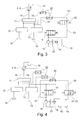
- the Fig. 6 schematically shows an internal combustion engine electric drive train of another mobile working machine according to the invention.
- the diesel engine 2 is connected to the hydraulic pump 5, which is designed as a variable displacement pump 9, and with a generator 30, which he drives. That of the generator 30, the one Three-phase generator 31 is generated electrical power is fed through a rectifier 32 into a DC voltage intermediate circuit 33. From the DC voltage intermediate circuit 33, a converter 34 is supplied with electrical energy, which drives a traction motor 35 as traction drive 3.
- the traction motor 35 is designed as a rotary field machine 36 and drives the drive wheels 37 at.
- a braking resistor 38 can be connected via a brake switch 39.
- a double-capacitor memory 41 or Ultracup memory can be connected to the DC intermediate circuit 33 via a further converter 40.
- the vehicle controller 8 may, in order to generate an additional load, increase the longitudinal field of the stator windings of the rotary field machine 36.
- the transverse field of the stator windings of the rotary field machine 36 can be connected to a high-frequency current.
Landscapes
- Engineering & Computer Science (AREA)
- Chemical & Material Sciences (AREA)
- Combustion & Propulsion (AREA)
- Mechanical Engineering (AREA)
- General Engineering & Computer Science (AREA)
- Control Of Vehicle Engines Or Engines For Specific Uses (AREA)
- Processes For Solid Components From Exhaust (AREA)
Abstract
Bei einem Verfahren zur Steuerung einer durch einen Dieselmotor (2) angetriebenen mobilen Arbeitsmaschine mit einem Rußpartikelfilter, mit einer Motorsteuerung, mit einer Fahrzeugsteuerung (8) und Erfassungsmitteln für einen Füllstand des Rußpartikelfilters sowie der Rußpartikelfiltertemperatur, überwacht die Fahrzeugsteuerung (8) den Füllstand des Rußpartikelfilters und die Rußpartikelfiltertemperatur, beurteilt die Notwendigkeit einer Rußpartikelfilterregeneration und, wenn die Motorsteuerung die Randbedingungen für eine Rußpartikelfiltergeneration nicht erreichen kann, insbesondere die Rußpartikelfiltertemperatur zu niedrig ist, erzeugt durch Ansteuerung von leistungaufnehmenden Komponenten der mobilen Arbeitsmaschine eine Zusatzlast für den Dieselmotor (2).In a method for controlling a mobile working machine driven by a diesel engine (2) with a soot particle filter, an engine controller, a vehicle controller (8) and soot particulate filter level detection means and soot particulate filter temperature, the vehicle controller (8) monitors the level of the soot particulate filter and the particulate filter temperature, judges the need for soot particulate filter regeneration and, if the engine control can not reach the constraints for soot particulate filter generation, in particular soot particulate filter temperature is too low, generates an additional load for the diesel engine (2) by driving power receiving components of the mobile work machine.
Description
Die Erfindung betrifft ein Verfahren zur Steuerung einer durch einen Dieselmotor angetriebenen mobilen Arbeitsmaschine mit Rußpartikelfilter. Insbesondere betrifft die Erfindung ein Verfahren zur Steuerung einer durch einen Dieselmotor angetriebenen mobilen Arbeitsmaschine mit einem Rußpartikelfilter, mit einer Motorsteuerung, mit einer Fahrzeugsteuerung und Erfassungsmitteln für einen Füllstand des Rußpartikelfilters sowie der Rußpartikelfiltertemperatur sowie eine entsprechende mobile Arbeitsmaschine.The invention relates to a method for controlling a driven by a diesel engine mobile machine with soot particle filter. In particular, the invention relates to a method for controlling a powered by a diesel engine mobile work machine with a particulate filter, with an engine control, with a vehicle control and detection means for a level of the particulate filter and the particulate filter temperature and a corresponding mobile machine.
Mobile Arbeitsmaschinen und als Ausführungsform insbesondere Flurförderzeuge werden oftmals durch einen Verbrennungsmotor angetrieben. Unter den Verbrennungsmotoren sind neben in seltenen Fällen mit Benzin betriebenen und treibgasbetriebenen Verbrennungsmotoren vor allem Dieselmotoren üblich. Um die bestehenden und zukünftig zu erwartende Abgasnormen zu erfüllen, müssen diese Dieselmotoren Abgasreinigungssysteme aufweisen, beispielsweise einen Rußpartikelfilter.Mobile machines and as an embodiment in particular industrial trucks are often driven by an internal combustion engine. Among the internal combustion engines are in addition to rare cases with gasoline-powered and propellant-powered internal combustion engines especially diesel engines usual. In order to meet the existing and future expected emission standards, these diesel engines must have exhaust gas purification systems, for example a soot particle filter.
Ein Beispiel für häufig zum Einsatz kommende Rußpartikelfilter sind permanent regenerierende (continuously regenerating trap bzw. CRT) die den angesammelten Ruß auf Basis chemischer Reaktionen in CO2 umsetzen. Dabei ist in dem Rußpartikelfilter zumeist eine katalytische Beschichtung vorhanden, die die Funktion erfüllt, CO und HC zu oxidieren sowie weiterhin NO zu NO2 und CO zu CO2. permanent regenerierende Systeme bzw. CRT-Systeme können vor allem bei Nutzfahrzeugmotoren eingesetzt werden, die in der Nähe des maximalen Drehmoments, somit bei vergleichsweise hohen Stickoxid (NOX)-Emissionen betrieben werden. Beispielsweise ist NO2 ein aktiveres Oxidationsmittel als O2 und bei solchen Systemen kann daher bereits bei relativ niedrigen Temperaturen eine Reaktion des Rußes mit NO2 erreicht werden. Hierfür kann beispielsweise ein Oxidationskatalysator stromaufwärts des Rußpartikelfilters angeordnet werden, der NO zu NO2 oxidiert. Nachteilig an diesem Stand der Technik ist jedoch, dass insbesondere bei Flurförderzeugen als Ausführungsbeispiel einer mobilen Arbeitsmaschine es vorkommen kann, dass die Einsatzbedingungen nur eine so extrem niedrige Auslastung des Flurförderzeugs verursachen, dass dieser chemische Prozess zum Rußabbau nicht stattfinden kann und der Rußpartikelfilter sich bis zur Beladungsgrenze füllt. In einem solchen Fall müssen die Flurförderzeuge dann abgestellt werden und es muss ein Prozess zur Reinigung des Rußpartikelfilters durchgeführt werden. Dadurch entstehen Ausfallzeiten und eventuell muss auch Arbeitszeit eingesetzt werden, um in einem speziellen Regenerationsbetrieb beispielsweise festgelegte Drehzahlen und eine Mindestbetriebstemperatur des Motors zu erreichen, die zu einem Freibrennen des Rußpartikelfilters führen.An example of frequently used soot particle filters are permanently regenerating (continuously regenerating traps or CRT) which convert the accumulated soot into CO2 on the basis of chemical reactions. In this case, in the soot particle filter usually a catalytic coating is present, which fulfills the function to oxidize CO and HC and further NO to NO 2 and CO to CO 2 . permanently regenerating systems or CRT systems can be used above all in commercial vehicle engines which are operated in the vicinity of the maximum torque, thus at comparatively high nitrogen oxide (NO x ) emissions. For example, NO 2 is more active oxidant than O 2, and therefore in such systems, a reaction of the carbon black with NO 2 can be achieved already at relatively low temperatures. For this purpose, for example, an oxidation catalyst can be arranged upstream of the soot particle filter, which oxidizes NO to NO 2 . A disadvantage of this prior art, however, is that in particular in industrial trucks as an embodiment of a mobile machine, it may happen that the conditions of use cause only so extremely low utilization of the truck that this chemical process for Rußabbau can not take place and the particulate filter up to Loading limit fills. In such a case, the trucks must then be turned off and it must be carried out a process for cleaning the particulate filter. This results in downtime and possibly also working time must be used to achieve, for example, specified speeds and a minimum operating temperature of the engine in a special regeneration operation, which lead to a burnout of the particulate filter.
Dieselmotoren für mobile Arbeitsmaschinen werden zumeist von den Motorenherstellern als komplette Einheiten einschließlich aller Nebenaggregate und insbesondere auch der Motorsteuerung verkauft, beispielsweise als sogenannte Industriemotoren. Diese Steuerungen weisen Steuerzyklen auf, die nach unterschiedlichen Konzepten, abhängig von dem jeweiligen Hersteller des Dieselmotors, den Betrieb des Dieselmotors so steuern, dass eine Regeneration des Rußpartikelfilters möglich wird. Insbesondere wird die Abgastemperatur durch die motoreigenen Steuerungen angehoben, etwa durch die Gemischregelung. Allerdings ist es bei allen bekannten System so, dass bei extrem niedriger Auslastung die physikalischen Grenzen erreicht werden und es den Motorsteuerungen nicht mehr gelingt, die Randbedingungen für eine Regeneration des Rußpartikelfilters zu erfüllen.Diesel engines for mobile machines are usually sold by the engine manufacturers as complete units including all accessories and in particular also the engine control, for example as so-called industrial engines. These controls have control cycles that, according to different concepts, depending on the particular manufacturer of the diesel engine, the operation of the diesel engine control so that a regeneration of the particulate filter is possible. In particular, the exhaust gas temperature is raised by the engine's own controls, such as through the mixture control. However, it is the case with all known systems that the physical limits are reached at extremely low utilization and the engine controls no longer succeed in fulfilling the boundary conditions for regeneration of the soot particle filter.
Der vorliegenden Erfindung liegt die Aufgabe zugrunde, ein Verfahren zur Steuerung einer verbrennungsmotorisch angetriebenenen mobilen Arbeitsmaschine mit einem Rußpartikelfilter sowie eine entsprechende mobile Arbeitsmaschine zur Verfügung zu stellen, die die oben genannten Nachteile vermeiden und mit denen ein kontinuierlicher Betrieb des Rußpartikelfilters möglich ist.The present invention has for its object to provide a method for controlling an internal combustion engine powered mobile machine with a particulate filter and a corresponding mobile machine available that avoid the above-mentioned disadvantages and with which a continuous operation of the particulate filter is possible.
Diese Aufgabe wird durch ein Verfahren mit den Merkmalen des unabhängigen Patentanspruchs 1 sowie eine mobile Arbeitsmaschine mit den Merkmalen des neben geordneten Anspruchs 18 gelöst. Vorteilhafte Weiterbildungen der Erfindung sind in den Unteransprüchen angegeben.This object is achieved by a method having the features of independent claim 1 and a mobile machine with the features of the next-to-
Die Aufgabe wird erfindungsgemäß dadurch gelöst, dass bei einem Verfahren zur Steuerung einer durch einen Dieselmotor angetriebenen mobilen Arbeitsmaschine mit einem Rußpartikelfilter, mit einer Motorsteuerung, mit einer Fahrzeugsteuerung und Erfassungsmitteln für einen Füllstand des Rußpartikelfilters sowie der Rußpartikelfiltertemperatur, die Fahrzeugsteuerung den Füllstand des Rußpartikelfilters und die Rußpartikelfiltertemperatur überwacht, die Notwendigkeit einer Rußpartikelfilterregeneration beurteilt und wenn die Motorsteuerung die Randbedingungen für eine Rußpartikelfiltergeneration nicht erreichen kann, insbesondere die Rußpartikelfiltertemperatur zu niedrig ist, durch Ansteuerung von leistungsaufnehmenden Komponenten der mobilen Arbeitsmaschine eine Zusatzlast für den Dieselmotor erzeugt.The object is achieved in that in a method for controlling a powered by a diesel engine mobile work machine with a particulate filter, with an engine control, with a vehicle control and detection means for a level of the particulate filter and the particulate filter temperature, the vehicle control the level of the particulate filter and the Monitoring particulate filter temperature, assessing the need for soot particulate filter regeneration, and if engine control can not meet the constraints for soot particulate filter generation, particularly particulate filter temperature is too low, generates additional load to the diesel engine by driving power-consuming components of the mobile work machine.
Dadurch kann auch bei einer sehr geringen Auslastung der mobilen Arbeitsmaschine erreicht werden, dass die Motorsteuerung mit ihren Regelungszyklen den Rußpartikelfilter regenerieren kann, insbesondere auch in einem permanenten Regenerierungsverfahren betreiben kann. Vor allem bei Flurförderzeugen, wie etwa Gabelstaplern, wird verhindert, dass beim Betrieb im Winter im Außengelände sowie in Kühlhäusern bei gleichzeitig nur geringer Belastung die Randbedingungen für eine Rußpartikelfilterregenerierung durch die Motorsteuerung nicht erreicht werden, insbesondere die Betriebstemperatur und vor allem die Abgastemperatur zu niedrig ist. Die Fahrzeugsteuerung überwacht dabei permanent den Füllstand des Rußpartikelfilters, dessen Temperatur und bewertet, ob eine Notwendigkeit für eine Regeneration des Rußpartikelfilters besteht. Wenn eine Notwendigkeit einer Regeneration besteht, wird die für den Dieselmotor notwendige Zusatzlast bestimmt, so dass die Motorsteuerung unter Randbedingungen arbeiten kann, in denen diese eine Regenerierung des Rußpartikelfilters durchführen kann, vor allem jedoch notwendige Abgastemperaturen erreicht werden können. Dieser Prozess findet andauernd statt und die Fahrzeugsteuerung passt eine Zusatzlast für den Dieselmotor kontinuierlich an den Bedarf an. Für die Bestimmung der Regenerationsnotwendigkeit wird vor allem auch die noch darstellbare Fahrzeugeinsatzzeit herangezogen. Dabei wird möglichst im Hinblick auf die Zusatzlast eine Minimierung hinsichtlich Größe und Zeitdauer angestrebt, da hierdurch ein erhöhter Kraftstoffverbrauch entsteht. Die leistungsaufnehmenden Komponenten der mobilen Arbeitsmaschine können dabei alle Arten von Arbeitsvorrichtungen sowie der Fahrantrieb sein, bei denen durch entsprechende Schaltung und/oder spezielle Einrichtungen eine erhöhte Verlustleistung erzeugt wird bzw. die Möglichkeit einer Leistungsaufnahme besteht, ohne dass unerwünschte Effekte auftreten.This can be achieved even at a very low utilization of the mobile machine that the engine control can regenerate the soot particle filter with their control cycles, in particular can operate in a permanent regeneration process. Especially for material handling equipment, such as forklifts, prevents the conditions for a soot particle filter regeneration by the engine control are not achieved when operating in the winter in the outdoor area and cold stores with low load, especially the operating temperature and especially the exhaust gas temperature is too low , The vehicle control system permanently monitors the fill level of the soot particle filter, its temperature and assesses whether there is a need for regeneration of the soot particle filter. If there is a need for regeneration, the additional load required for the diesel engine is determined, so that the engine control can work under marginal conditions in which it can perform a regeneration of the particulate filter, but above all, necessary exhaust gas temperatures can be achieved. This process is ongoing and the vehicle control system continuously adjusts an additional load for the diesel engine to the demand. For the determination of the need for regeneration above all the still representable vehicle use time is used. As far as possible, with regard to the additional load, a minimization in terms of size and duration is sought, as this results in an increased fuel consumption. The power-consuming components of the mobile work machine can be all types of working devices and the traction drive, where increased by appropriate circuitry and / or special facilities Power loss is generated or the possibility of power consumption without unwanted effects occur.
In einer vorteilhaften Ausgestaltung des Verfahrens beurteilt die Fahrzeugsteuerung weitere Regenerationsrandbedingungen, insbesondere ein bisheriges Einsatzprofil der mobilen Arbeitsmaschine.In an advantageous embodiment of the method, the vehicle controller assesses further regeneration boundary conditions, in particular a previous deployment profile of the mobile work machine.
Dies ermöglicht eine weitere Präzisierung der Steuerung der Zusatzlast.This allows a further specification of the control of the additional load.
Die Fahrzeugsteuerung kann den Füllstand des Rußpartikelfilters und/oder die Rußpartikelfiltertemperatur und/oder die Notwendigkeit einer Rußpartikelfilterregeneration von der Motorsteuerung abfragen.The vehicle controller may interrogate the level of the particulate filter and / or the particulate filter temperature and / or the need for soot particulate filter regeneration from the engine controller.
Die genannten Parameterwerte stehen in der Motorsteuerung regelmäßig zur Verfügung. Soweit die Daten aus der Motorsteuerung über eine Schnittstelle abgefragt werden können, kann auf einfache Art und Weise die Fahrzeugsteuerung diese Parameterwert erhalten. Vorteilhaft lässt sich dann das beschriebene Verfahren allein durch Software ohne zusätzliche Bauelemente umsetzen, soweit keine Anpassung der leistungaufnehmenden Komponenten erforderlich ist. Dies ist beispielsweise bei einem verbrennungsmotorisch-elektrischen Antriebsstrang möglich, bei dem durch einen Generator elektrische Energie erzeugt wird, die elektrischen Fahrmotoren zugeführt wird. Bei letzteren ist es möglich, ohne weitere mechanische Anpassung eine Verlustleistung zu erzeugen. Ebenfalls denkbar ist die Nutzung eines bereits vorhandenen Bremswiderstands für eine elektrische Bremse über die Fahrmotoren.The mentioned parameter values are regularly available in the engine control. As far as the data from the engine control can be interrogated via an interface, the vehicle control can obtain this parameter value in a simple manner. Advantageously, the method described can then be implemented solely by software without additional components, as far as no adaptation of the power-consuming components is required. This is possible, for example, in an internal combustion engine-electric drive train, in which electrical energy is generated by a generator, which is supplied to electric traction motors. With the latter, it is possible to generate a power loss without further mechanical adjustment. Also conceivable is the use of an existing braking resistor for an electric brake on the traction motors.
Die Zusatzlast kann durch eine Erhöhung des hydraulischen Drucks einer Hydraulikanlage erzeugt werden.The additional load can be generated by increasing the hydraulic pressure of a hydraulic system.
Vorteilhaft wird durch ein parallel zu hydraulischen Verbrauchern angeordnetes Schaltventil bei einer Load-Sensing-Regelung der Pumpendruck auf die Load-Sensing-Steuerleitung von der Fahrzeugsteuerung geschaltet.Advantageously, the pump pressure is switched to the load-sensing control line of the vehicle control by a switching valve arranged parallel to hydraulic consumers in a load-sensing control.
Bei einem klassischen Load-Sensing-System (LS-System), beispielsweise in Closed-Center Bauweise, wird der maximale Lastdruck aller hydraulischen Verbraucher an die Pumpe bzw. eine Lastdruckwaage zur Ansteuerung der Pumpe gemeldet. Im Leerlauf des Dieselmotors und wenn alle hydraulischen Verbrauchern keine Leistung abrufen, werden die LS-Drücke über die einzelnen Verbraucher entlastet und die Hydraulikpumpe wird auf die Regeldruckdifferenz der Lastdruckwaage als Ausgangsdruck zurück geschwenkt. Durch das Schaltventil wird der Ausgangsdruck der Hydraulikpumpe unmittelbar auf den LS-Steuerdruck geschaltet. Durch diese unmittelbare Addition der Regeldruckdifferenz wird der Ausgangsdruck der Hydraulikpumpe bis zum maximalen Systemdruck erhöht.In a classic load-sensing system (LS system), for example in closed-center design, the maximum load pressure of all hydraulic consumers to the pump or a load pressure compensator for controlling the pump is reported. Idle of the diesel engine and if all hydraulic consumers do not call up any power, the LS pressures are relieved via the individual consumers and the hydraulic pump is swiveled back to the control pressure difference of the load pressure compensator as output pressure. By the switching valve, the output pressure of the hydraulic pump is switched directly to the LS control pressure. By this immediate addition of the control pressure difference, the output pressure of the hydraulic pump is increased up to the maximum system pressure.
Ein hydraulischer Verbraucher kann ein Lüftermotor sein.A hydraulic consumer may be a fan motor.
Der Lüftermotor für einen Motorkühler bzw. beispielsweise auch einen Hydraulikkühler muss bei einer mobilen Arbeitsmaschine und insbesondere bei einem Flurförderzeug im Regelfall während des Betriebs laufen, da kein nennenswerter Fahrtwind für einen Kühlluftstrom zur Verfügung steht. Der Lüftermotor kann beispielsweise ein hydraulischer Zahnradmotor sein, der durch ein Druckminderventil angesteuert wird. Der Lastdruck des Lüftermotors kann dann über eine Kaskade von Wechselventilen in die LS-Leitung geleitet werden zur Ansteuerung der Hydraulikpumpe.The fan motor for a radiator or, for example, a hydraulic radiator must run in a mobile machine and especially in a truck usually during operation, as no significant wind for a cooling air flow is available. The fan motor may for example be a hydraulic gear motor, which is controlled by a pressure reducing valve. The load pressure of the fan motor can then be passed via a cascade of shuttle valves in the LS line to control the hydraulic pump.
In einer günstigen Ausgestaltung des Verfahrens wird ein Schaltventil in einer Load-Sensing-Leitung eines Lüftermotors in eine Sperrstellung von der Fahrzeugsteuerung geschaltet.In a favorable embodiment of the method, a switching valve is switched in a load-sensing line of a fan motor in a blocking position of the vehicle control.
Der Druck der Hydraulikpumpe kann auf den maximalen Systemdruck erhöht werden, da die LS-Entlastung über den Verbraucher des Elektromotors bei gesperrtem Schaltventil nicht möglich ist.The pressure of the hydraulic pump can be increased to the maximum system pressure, as the LS relief via the load of the electric motor with locked switching valve is not possible.
In beiden zuvor beschriebenen Fällen kann die Zusatzlast in dem Hydrauliksystem weiter gesteigert werden, indem der Lüftermotor bei einer höheren Drehzahl betrieben wird, als für den Kühlzweck erforderlich wäre. Dadurch wird der Volumenstrom der Hydraulikpumpe erhöht und ergibt sich eine größere Zusatzlast, die durch das Produkt aus Druck und Volumenstrom bestimmt wird.In both cases described above, the extra load in the hydraulic system can be further increased by operating the fan motor at a higher speed than would be required for the cooling purpose. As a result, the volume flow of the hydraulic pump is increased and results in a larger additional load, which is determined by the product of pressure and flow.
Vorteilhaft wird die Zusatzlast durch eine Erhöhung der hydraulischen Verlustleistung einer Hydraulikanlage erzeugt.Advantageously, the additional load is generated by increasing the hydraulic power loss of a hydraulic system.
Es kann parallel zu einer Arbeitshydraulik eine Blende angeordnet sein, über die Hydraulikfluid in einen Tank abströmen kann.It can be arranged parallel to a working hydraulics, a diaphragm, can flow through the hydraulic fluid into a tank.
Die Blende wird dabei als ein weiterer Verbraucher, an dem eine Verlustleistung entsteht. Diese Verlustleistung bildet die Zusatzlast und ist proportional zu dem Produkt aus Druck und Volumenstrom an der Blende.The aperture is considered as another consumer, where a power loss occurs. This power loss forms the additional load and is proportional to the product of pressure and flow at the aperture.
Die Blende kann regelbar sein.The aperture can be adjustable.
Ein Ventil zur Betätigung der Blende bzw. dass die Blende bildet, kann dabei als Schalt- oder Proportionalventil ausgeführt seinA valve for actuating the diaphragm or that forms the diaphragm can be designed as a switching or proportional valve
In günstiger Ausführungsform erzeugt die Blende einen Steuerdruck auf einer Load-Sensing-Leitung.In a favorable embodiment, the diaphragm generates a control pressure on a load-sensing line.
Dies ist umsetzbar mit einem Proportionalventil und einer entsprechenden LS-Rückführung und ermöglicht die Steuerung der hydraulischen Verlustleistung und somit der Zusatzlast. Bei nicht betätigtem Proportionalventil wird die LS-Leitung zu einem Tank hin entlastet.This can be implemented with a proportional valve and a corresponding LS feedback and allows the control of the hydraulic power loss and thus the additional load. If the proportional valve is not actuated, the LS line is relieved to a tank.
Vorteilhaft ist parallel mit der Blende ein Lüftermotor angeordnet ist und das Hydraulikfluid aus beiden wird über einen Kühler in einen Tank abgeleitet, wobei an einem Zulauf von der Blende zu dem Kühler und von dem Lüftermotor zu dem Kühler jeweils ein Rückschlagventil angeordnet ist.Advantageously, a fan motor is arranged in parallel with the diaphragm and the hydraulic fluid from both is discharged via a radiator into a tank, wherein a check valve is arranged at an inlet from the diaphragm to the radiator and from the fan motor to the radiator.
Wenn das Hydraulikfluid nach der Blende über einen Kühler zum Tank zurückgeführt werden soll, so sind zwei Rückschlagventile notwendig, um Wechselwirkungen mit dem zweiten Rücklauf des Lüftermotors zu dem Tank zu vermeiden.If the hydraulic fluid is to be returned to the tank after the orifice via a cooler, two check valves are necessary to avoid interference with the second return of the fan motor to the tank.
Die Zusatzlast kann durch eine Erhöhung der elektrischen Verlustleistung eines verbrennungsmotorisch-elektrischen Fahrantriebs erzeugt werden.The additional load can be generated by increasing the electrical power loss of a combustion engine-electric traction drive.
Bei einem verbrennungsmotorisch-elektrischen Fahrantrieb erzeugt ein mit den Dieselmotor in Verbindung stehender Generator, bevorzugt ein dreiphasiger Drehstromgenerator, elektrischen Strom, der über einen Gleichrichter, einen Gleichspannungszwischenkreis und einen Umrichter an im Regelfall Drehstrommotoren als Fahrantriebsmotoren übertragen wird. Eine Zusatzlast lässt sich daher leicht erzeugen, wenn über elektrische Regelungen eine Belastung des Generators verursacht wird und vermehrt elektrische Leistung abgerufen wird, die einer Energiesenke zugeleitet wird.In an internal combustion engine-electric traction drive, a generator connected to the diesel engine, preferably a three-phase alternator, generates electrical power via a rectifier DC voltage intermediate circuit and a converter to be transmitted to three-phase motors as traction motors usually. An additional load can therefore be easily generated when a load on the generator is caused by electrical regulations and more electrical power is called, which is fed to an energy sink.
Der Fahrmotor der mobilen Arbeitsmaschine kann eine Drehfeldmaschine sein und die elektrische Verlustleistung kann durch eine Erhöhung eines Fahrmotorenlängsfeldes erfolgen.The drive motor of the mobile work machine can be an induction machine and the electrical power loss can be achieved by increasing a drive motor longitudinal field.
Bei einer Ausführung des Fahrmotors oder der Fahrmotoren als Drehfeldmaschine, wie etwa beispielsweise als asynchronem Drehstrommotor, ist eine Erhöhung der Feldstärke eines Längsfeldes in Bezug auf eine Achse des Fahrmotors ohne Einfluss auf die Drehmomentbildung. Diese erhöhten Staplerströme führen zu einer quadratisch zunehmenden Verlustleistung in den Statorwicklungen. Die dabei entstehende Abwärme wird über das für die Fahrmotoren vorgesehenen Kühlsystem abgeführt, etwa durch eine Luft- oder Flüssigkeitskühlung.In an embodiment of the traction motor or traction motors as a rotating field machine, such as, for example, as an asynchronous three-phase motor, an increase in the field strength of a longitudinal field with respect to an axis of the traction motor without influence on the torque. These increased stacker currents lead to a quadratically increasing power dissipation in the stator windings. The resulting waste heat is dissipated via the provided for the traction motors cooling system, such as air or liquid cooling.
In einer Ausgestaltung des Verfahrens ist ein Fahrmotor der mobilen Arbeitsmaschine eine Drehfeldmaschine und erfolgt die elektrische Verlustleistung durch hochfrequente Fahrmotorquerfelder.In one embodiment of the method, a drive motor of the mobile work machine is an induction machine and the electrical power loss is performed by high-frequency traction motor transverse fields.
Die mechanischen Komponenten des Fahrantriebs einschließlich einer Torsionsfederwirkung der Reifen weist einen Dämpfungscharakter auf. Insgesamt ergibt sich ein Tiefpasscharakter der Achsmechanik, so dass hochfrequente Drehschwingungen des Fahrantriebs kein Bewegungsmoment auf das Fahrzeug bewirken.The mechanical components of the traction drive including a torsion spring action of the tire has a damping character. Overall, a low-pass character of the axle mechanism results, so that high-frequency torsional vibrations of the traction drive cause no movement moment on the vehicle.
Vorteilhaft erfolgt die elektrische Verlustleistung durch eine Aufschaltung eines Bremswiderstandes.Advantageously, the electrical power loss takes place by connecting a braking resistor.
Bei vielen mobilen Arbeitsmaschinen und insbesondere Flurförderzeugen steht eine elektrische Bremse zur Verfügung, indem elektrische Fahrantriebsmotoren in einem Generatorbetrieb elektrischer Leistung erzeugen. Diese Leistung wird oftmals in einem Bremswiderstand als Energiesenke vernichtet. Dabei wird der in den Drehstrommotoren entstehende Drehstrom über einen Frequenzumrichter, auch bezeichnet als Bremschopper, dem Bremswiderstand zugeleitet. Vorteilhaft kann der Bremswiderstand auch für die Erzeugung einer Zusatzlast für den Dieselmotor eingesetzt werden und ist insbesondere keine mechanische Änderung der mobilen Arbeitsmaschine oder des Flurförderzeugs erforderlich.In many mobile machines and especially industrial trucks, an electric brake is available by generating electric traction motors in a generator operation of electrical power. This power is often destroyed in a braking resistor as an energy sink. It will be in the Three-phase motors resulting three-phase current via a frequency converter, also referred to as a brake chopper, fed to the braking resistor. Advantageously, the braking resistor can also be used for generating an additional load for the diesel engine and, in particular, no mechanical change of the mobile working machine or of the industrial truck is required.
Die elektrische Verlustleistung kann durch Zuführung elektrischer Leistung zu einem elektrischen Energiespeicher eines Hybridsystems erfolgen, insbesondere einer Hochvoltbatterie und/oder eines Doppelkondensatorspeichers.The electrical power loss can be done by supplying electrical power to an electrical energy storage of a hybrid system, in particular a high-voltage battery and / or a double-capacitor memory.
Wenn es sich bei der mobilen Arbeitsmaschine, insbesondere einem Flurförderzeug, um ein Hybridsystem handelt, dass neben dem Dieselmotor mit Generator zur Erzeugung von elektrischer Leistung auch Speichermöglichkeiten für die elektrische Leistung aufweist, so kann vorteilhaft der Gesamtwirkungsgrad verbessert werden und muss die Zusatzleistung nicht in reine Verlustleistung umgesetzt werden.If the mobile working machine, in particular an industrial truck, is a hybrid system which, in addition to the diesel engine with a generator for generating electrical power, also has storage possibilities for the electric power, then advantageously the overall efficiency can be improved and the additional power must not be reduced to pure Power loss to be implemented.
Es ist auch denkbar, eine Zusatzlast durch den bei einem Dieselmotor vorgesehenen Generator zum Aufladen der Starterbatterie, auch bezeichnet als Lichtmaschine, zu erzeugen. Auch bei dieser kann durch eine entsprechende elektrische Last eine Zusatzlast erzeugt werden.It is also conceivable to generate an additional load by the generator provided in a diesel engine for charging the starter battery, also referred to as an alternator. Even with this, an additional load can be generated by a corresponding electrical load.
Die Aufgabe wird auch gelöst durch eine mobile Arbeitsmaschine mit einem Antrieb durch einen Dieselmotor mit einem Rußpartikelfilter, mit einer Motorsteuerung, sowie mit einer Fahrzeugsteuerung, bei der die Fahrzeugsteuerung durch ein parallel zu hydraulischen Verbrauchern angeordnetes Schaltventil bei einer Load-Sensing-Regelung den Pumpendruck auf die Load-Sensing-Steuerleitung schalten kann, oder ein Schaltventil in einer Load-Sensing-Leitung eines Lüftermotors in eine Sperrstellung schalten kann, oder eine regelbare Blende parallel zu einer Arbeitshydraulik ansteuern kann, insbesondere eine Blende, die einen Steuerdruck auf einer Load-Sensing-Leitung erzeugen kann.The object is also achieved by a mobile work machine with a drive by a diesel engine with a soot particle filter, with a motor control, and with a vehicle control, in which the vehicle control by a parallel to hydraulic consumers arranged switching valve in a load-sensing control the pump pressure the load-sensing control line can switch, or switch a switching valve in a load-sensing line of a fan motor in a blocking position, or can control a controllable orifice in parallel to a working hydraulics, in particular a diaphragm, the control pressure on a load-sensing Line can generate.
Die Mobile Arbeitsmaschine weist die bereits zuvor genannten Vorteile auf. Durch die verschiedenen, alternativen Möglichkeiten der Erzeugung einer zusätzlichen Last für den Dieselmotor kann das zuvor beschriebene Verfahren durchgeführt werden. Grundsätzlich ist es auch denkbar, dass die alternativ dargestellten Möglichkeiten auch alle drei gleichzeitig oder je zwei zugleich zum Einsatz kommen.The mobile work machine has the advantages mentioned above. By the various alternative ways of generating an additional load for the diesel engine, the method described above can be carried out. In principle, it is also conceivable that the alternatives presented as alternatives all three at the same time or two at a time are used.
Vorteilhaft sind Erfassungsmitteln für einen Füllstand des Rußpartikelfilters sowie die Rußpartikelfiltertemperatur vorhanden sind und führt die Fahrzeugsteuerung ein zuvor beschriebenes Verfahren durch.Advantageously, detection means for a fill level of the soot particle filter as well as the soot particle filter temperature are present and the vehicle controller carries out a previously described method.
Bei den zuvor genannten Varianten mit einem verbrennungsmotorisch-elektrischen Antriebsstrang ist dann keine mechanische Anpassung erforderlich und kann das beschriebene Verfahren bzw. die beschriebene mobile Arbeitsmaschine allein durch eine softwaremäßige Anpassung umgesetzt werden.In the aforementioned variants with an internal combustion engine-electric drive train then no mechanical adjustment is required and the described method or the described mobile work machine can be implemented solely by a software adaptation.
Die mobile Arbeitsmaschine kann ein Flurförderzeug sein.The mobile work machine can be an industrial truck.
Gerade bei Flurförderzeugen ergeben sich durch die Erfindung große Vorteile. Abhängig von der jeweiligen Einsatzsituation in einem Betriebsgelände werden Gabelstapler teilweise nur mit sehr geringer Auslastung bei Bedarf eingesetzt. Wenn dies auch noch in einem Kühlhaus oder im Winter in einem Freigelände der Fall ist, kann durch die Erfindung dennoch eine kontinuierliche Regeneration des Rußpartikelfilters sichergestellt werden und ergeben sich keine Beeinträchtigungen des Betriebs oder Ausfallzeiten. Es wird auch die Gefahr von Schäden des Rußpartikelfilters vermieden.Especially for trucks resulting from the invention great advantages. Depending on the particular operational situation in a company premises, forklift trucks are sometimes used only with very low utilization if required. Although this is still the case in a cold store or in winter in an open-air area, the invention can nevertheless ensure a continuous regeneration of the soot particle filter and results in no impairment of operation or downtime. It also avoids the risk of damage to the particulate filter.
Durch die Erfindung werden Ausfallzeiten eines Flurförderzeugs bzw. einer mobilen Arbeitsmaschine vermieden. Durch eine optimierte Aufprägung einer Zusatzlast kommt es zu einer Minimierung des für eine sichere Rußpartikelfilterregeneration notwendigen Kraftstoffmehrverbrauchs. Es ergibt sich auch kein Einfluss der Rußpartikelfilterregenerierung auf die Einsetzbarkeit des Flurförderzeugs. In der Regel ist davon auszugehen, dass von einem Fahrer die Durchführung des Verfahrens nicht oder nur minimal wahrgenommen wird und daher auch von einer großen Akzeptanz bei den Fahrern auszugehen ist.The invention avoids downtime of a truck or a mobile machine. An optimized application of an additional load minimizes the additional fuel consumption required for reliable soot particle filter regeneration. There is also no influence of the soot particle filter regeneration on the applicability of the truck. As a rule, it is to be assumed that the driver is not or only minimally aware of the implementation of the procedure and that therefore a high level of acceptance among the drivers is to be assumed.
Weitere Vorteile und Einzelheiten der Erfindung werden anhand der in den schematischen Figuren dargestellten Ausführungsbeispiele näher erläutert. Hierbei zeigt
- Fig. 1
- schematisch den Leistungsfluss bei einer mobilen Arbeitsmaschine, bei der das erfindungsgemäße Verfahren zum Einsatz kommt,
- Fig. 2
- schematisch einen hydraulischen Schaltplan einer erfindungsgemäßen mobilen Arbeitsmaschine,
- Fig. 3
- schematisch einen hydraulischen Schaltplan einer weiteren erfindungsgemäßen mobilen Arbeitsmaschine,
- Fig. 4
- schematisch einen hydraulischen Schaltplan einer weiteren erfindungsgemäßen mobilen Arbeitsmaschine,
- Fig. 5
- schematisch einen hydraulischen Schaltplan einer weiteren erfindungsgemäßen mobilen Arbeitsmaschine und
- Fig. 6
- schematisch einen verbrennungsmotorisch elektrischen Antriebsstrang einer weiteren erfindungsgemäßen mobilen Arbeitsmaschine.
- Fig. 1
- schematically the power flow in a mobile work machine, in which the inventive method is used,
- Fig. 2
- 1 schematically a hydraulic circuit diagram of a mobile working machine according to the invention,
- Fig. 3
- 1 schematically a hydraulic circuit diagram of a further mobile working machine according to the invention,
- Fig. 4
- 1 schematically a hydraulic circuit diagram of a further mobile working machine according to the invention,
- Fig. 5
- schematically a hydraulic circuit diagram of another mobile working machine according to the invention and
- Fig. 6
- schematically an internal combustion engine electric drive train of another mobile working machine according to the invention.
Die
Eine Fahrzeugsteuerung 8 erhält Daten und Parameterwerte von dem Dieselmotor 2 bzw. dessen Motorsteuerung und von dem Fahrantrieb 3 wie auch der Hydraulikpumpe 5 bzw. der Hydraulik. Die Fahrzeugsteuerung 8 erzeugt durch Ansteuerung von leistungsaufnehmenden Komponenten der mobilen Arbeitsmaschine eine Zusatzlast für den Dieselmotor 2, wenn die Randbedingungen nicht mehr gegeben sind, unter denen die Motorsteuerung eine Rußpartikelfilterregenerierung durchführen kann und wenn eine Rußpartikelfilterregenerierung erforderlich ist.A
Die
Von der Lenkung 12, der Arbeitshydraulik 13 und dem Lüftermotor 15 wird jeweils der Lastdruck abgegriffen und über eine LS-Leitung 19 und eine Kaskade aus Wechselventilen 20 einer nicht näher dargestellten LS-Steuerung der Verstellpumpe 9 zugeführt.Of the
Durch ein Schaltventil 21, dass parallel zu der Arbeitshydraulik 13 und dem Lüftermotor 15 angeordnet ist, wird bei einer Zusatzlast der Förderdrucks direkt auf die LS-Leitung 19 geschaltet. Wenn das Schaltventil 21 nicht geschaltet ist, findet ein Normalbetrieb statt mit der bekannten LS-Regelung, bei der im Leerlauf des Dieselmotors die einzelnen LS-Drücke über die einzelnen Verbraucher entlastet werden. Die Verstellpumpe 9 wird auf die Regeldruckdifferenz zurück geregelt und geschwenkt. Wird das Schaltventil 21 geschaltet, so wird der anstehende Förderdruck der Verstellpumpe 9 über die LS-Leitung 19 und die Wechselventile 20 an die LS-Steuerung zurückgemeldet. Dadurch wird die Regeldruckdifferenz auf den LS-Druck als Rückführgröße der Regelung unmittelbar aufaddiert und die Verstellpumpe 9 bis zur Förderung des maximalen Systemdrucks aufgeschwenkt.By a switching
Die Zusatzlast kann weiter gesteigert werden, indem der Lüftermotor 15 mit einer höheren Drehzahl betrieben wird, um den Volumenstrom des Hydraulikfluids zu erhöhen. Dies kann erfolgen, indem das Druckregelventil 14 weiter geöffnet wird.The additional load can be further increased by the
Die
Der Lastdruck der Lenkung 12, der Arbeitshydraulik 13 und des Lüftermotors 15 wird über die LS-Leitung 19 und die Kaskade aus den Wechselventilen 20 einer nicht näher dargestellten LS-Steuerung der Verstellpumpe 9 zugeführt.The load pressure of the
Ein Schaltventil 22 ist in einer LS-Leitung 23 des Lüftermotors 15 angeordnet. Der Förderdrucks der Verstellpumpe 9 kann auf den maximalen Systemdruck erhöht werden, da die LS-Entlastung über den Verbraucher Lüftermotor 15 nicht möglich ist.A switching
Auch bei diesem Ausführungsbeispiel kann über das Druckregelventil 14 die Zusatzlast weiter gesteigert werden, indem der Lüftermotor 15 mit einer höheren Drehzahl und damit erhöhtem Volumenstrom betrieben wird.Also in this embodiment, the additional load can be further increased by the
Die
Der Lastdruck der Lenkung 12, der Arbeitshydraulik 13 und des Lüftermotors 15 wird über die LS-Leitung 19 und die Kaskade aus den Wechselventilen 20 der LS-Steuerung der Verstellpumpe 9 zugeführt.The load pressure of the
Parallel zu der Arbeitshydraulik 13 und dem Lüftermotor 15 ist eine Blende 24 angeordnet, die als Proportionalventil 25 ausgebildet ist, das mit zunehmender Drosselung einen Steuerdruck für eine LS-Leitung 26 erzeugt. Von der Blende 24 strömt das Hydraulikfluid in den Tank 18.Parallel to the working
Wenn das Proportionalventil 25 zunehmend geschlossen wird und die Blende 24 eine ansteigende Drossel Wirkung erzeugt, entsteht eine Zusatzlast für den Dieselmotor 2. Diese Zusatzlast wird noch dadurch verstärkt, dass über die LS-Regelung die Leistung der Verstellpumpe 9 erhöht wird, die gegen die Blende 24 arbeitet.If the proportional valve 25 is increasingly closed and the diaphragm 24 produces an increasing throttle effect, an additional load for the
Die
Der Lastdruck der Lenkung 12, der Arbeitshydraulik 13 und des Lüftermotors 15 wird über die LS-Leitung 19 und die Kaskade aus den Wechselventilen 20 der LS-Steuerung der Verstellpumpe 9 zugeführt. Parallel zu der Arbeitshydraulik 13 ist die Blende 24 als Proportionalventil 25 angeordnet mit der LS-Leitung 26.The load pressure of the
Gegenüber der Ausführungsform der
Die
Mit dem Gleichspannungszwischenkreis 33 kann ein Bremswiderstand 38 über einen Bremsschalter 39 verbunden werden. Ebenso kann über einen weiteren Umrichter 40 ein Doppelkondensatorspeicher 41 oder Ultracup-Speicher mit dem Gleichspannungszwischenkreis 33 verbunden werden.With the DC voltage
Die Fahrzeugsteuerung 8 kann, um eine Zusatzlast zu erzeugen, das Längsfeld der Statorwicklungen der Drehfeldmaschine 36 erhöhen. Alternativ oder zusätzlich kann auch das Querfeld der Statorwicklungen der Drehfeldmaschine 36 mit einem hochfrequenten Strom beschaltet werden.The
Ebenso ist es möglich, eine Zusatzlast zu erzeugen, indem über den Bremsschalter 39 der Bremswiderstand 38 eingeschaltet wird und in dem Bremswiderstand 38 elektrische Energie in Wärme umgewandelt wird. Um Leistungsverluste zu vermeiden, ist es bei dem hier dargestellten Hybridsystem auch möglich, über den weiteren Umrichter 40 elektrische Energie in dem Doppelkondensatorspeicher 41 zu laden und dadurch eine Zusatzlast zu erzeugen.It is also possible to generate an additional load by switching on the
In allen vorgenannten Fällen in steht die Zusatzlast für den Dieselmotor 2 dadurch, dass der Generator 30 ein größeres Lastmoment aufweist.In all the above cases in the additional load for the
Claims (20)
dadurch gekennzeichnet,
dass die Fahrzeugsteuerung (8) den Füllstand des Rußpartikelfilters und die Rußpartikelfiltertemperatur überwacht, die Notwendigkeit einer Rußpartikelfilterregeneration beurteilt und, wenn die Motorsteuerung die Randbedingungen für eine Rußpartikelfiltergeneration nicht erreichen kann, insbesondere die Rußpartikelfiltertemperatur zu niedrig ist, durch Ansteuerung von leistungaufnehmenden Komponenten der mobilen Arbeitsmaschine eine Zusatzlast für den Dieselmotor (2) erzeugt.Method for controlling a mobile working machine driven by a diesel engine (2) with a soot particle filter, with an engine control system, with a vehicle control system (8) and soot particle filter fill-up means and soot particle filter temperature,
characterized,
that the vehicle controller (8) monitors the soot particulate filter and soot particulate filter temperature, judges the need for soot particulate filter regeneration, and, if the engine control can not reach the soot particulate filter generation constraints, especially the soot particulate filter temperature is too low, by driving power-receiving components of the mobile work machine Additional load for the diesel engine (2) generated.
dadurch gekennzeichnet,
dass die Fahrzeugsteuerung weitere Regenerationsrandbedingungen beurteilt, insbesondere ein bisheriges Einsatzprofil der mobilen Arbeitsmaschine.Method according to claim 1,
characterized,
that the vehicle controller judges more regeneration conditions, in particular a previous operating profile of the mobile working machine.
dadurch gekennzeichnet,
dass die Fahrzeugsteuerung den Füllstand des Rußpartikelfilters und/oder die Rußpartikelfiltertemperatur und/oder die Notwendigkeit einer Rußpartikelfilterregeneration von der Motorsteuerung abfragt.Method according to claim 1 or 2,
characterized,
that the vehicle controller polls the level of soot particle filter and / or the particulate filter temperature and / or the need for a particulate filter regeneration by the motor controller.
dadurch gekennzeichnet,
dass die Zusatzlast durch eine Erhöhung des hydraulischen Drucks einer Hydraulikanlage erzeugt wird.Method according to one of claims 1 to 3,
characterized,
that the additional load is generated by increasing the hydraulic pressure of a hydraulic system.
dadurch gekennzeichnet,
dass durch ein parallel zu hydraulischen Verbrauchern angeordnetes Schaltventil (21) bei einer Load-Sensing-Regelung der Pumpendruck auf die Load-Sensing-Steuerleitung (19) von der Fahrzeugsteuerung (8) geschaltet wird.Method according to claim 4,
characterized,
that by a parallel to hydraulic consumers arranged switching valve (21) in a load-sensing control of the pump pressure to the load-sensing control line (19) is switched by the vehicle controller (8).
dadurch gekennzeichnet,
dass ein hydraulischer Verbraucher ein Lüftermotor (15) ist.Method according to claim 5,
characterized,
that a hydraulic load is a fan motor (15).
dadurch gekennzeichnet,
dass ein Schaltventil (22) in einer Load-Sensing-Leitung (23) eines Lüftermotors (15) in eine Sperrstellung von der Fahrzeugsteuerung (8) geschaltet wird.Method according to claim 4,
characterized,
in that a switching valve (22) in a load-sensing line (23) of a fan motor (15) is switched to a blocking position by the vehicle control (8).
dadurch gekennzeichnet,
dass die Zusatzlast durch eine Erhöhung der hydraulischen Verlustleistung einer Hydraulikanlage erzeugt wird.Method according to one of claims 1 to 7,
characterized,
that the additional load is generated by increasing the hydraulic power loss of a hydraulic system.
dadurch gekennzeichnet,
dass parallel zu einer Arbeitshydraulik (13) eine Blende (24) angeordnet ist, über die Hydraulikfluid in einen Tank (18) abströmen kann.Method according to claim 8,
characterized,
in that a diaphragm (24) is arranged parallel to a working hydraulic system (13), via which hydraulic fluid can flow into a tank (18).
dadurch gekennzeichnet,
dass die Blende (24) regelbar ist.Method according to claim 9,
characterized,
that the diaphragm (24) is adjustable.
dadurch gekennzeichnet,
dass die Blende (24) einen Steuerdruck auf einer Load-Sensing-Leitung (26) erzeugt.Method according to claim 10,
characterized,
in that the diaphragm (24) generates a control pressure on a load-sensing line (26).
dadurch gekennzeichnet,
dass parallel mit der Blende (24) ein Lüftermotor (15) angeordnet ist und das Hydraulikfluid aus beiden über einen Kühler (16) in einen Tank (18) abgeleitet wird, wobei an einem Zulauf (18) von der Blende (24) zu dem Kühler (16) und von dem Lüftermotor (15) zu dem Kühler (16) jeweils ein Rückschlagventil (27) angeordnet ist.Method according to claim 10,
characterized,
that a fan motor (15) is arranged parallel to the diaphragm (24) and the hydraulic fluid is drained from both via a cooler (16) into a tank (18), wherein at an inlet (18) from the diaphragm (24) to the Cooler (16) and of the fan motor (15) to the radiator (16) in each case a check valve (27) is arranged.
dadurch gekennzeichnet,
dass die Zusatzlast durch eine Erhöhung der elektrischen Verlustleistung eines verbrennungsmotorisch-elektrischen Fahrantriebs erzeugt wird.Method according to one of claims 1 to 10,
characterized,
that the additional load is generated by increasing the electrical power loss of an internal combustion engine electric traction drive.
dadurch gekennzeichnet,
dass ein Fahrmotor (35) der mobilen Arbeitsmaschine eine Drehfeldmaschine (36) ist und die elektrische Verlustleistung durch eine Erhöhung eines Fahrmotorlängsfeldes erfolgt.Method according to claim 13,
characterized,
in that a traction motor (35) of the mobile working machine is an induction machine (36) and the electric power loss is achieved by increasing a traction motor longitudinal field.
dadurch gekennzeichnet,
dass ein Fahrmotor (35) der mobilen Arbeitsmaschine eine Drehfeldmaschine (36) ist und die elektrische Verlustleistung durch hochfrequente Fahrmotorquerfelder erfolgt.Method according to claim 13 or 14,
characterized,
that a driving motor (35) of the mobile work machine is an induction machine (36) and provide the electrical power loss by high-frequency drive motor transverse fields.
dadurch gekennzeichnet,
dass die elektrische Verlustleistung durch eine Aufschaltung eines Bremswiderstandes (38) erfolgt.Method according to one of claims 13 to 15,
characterized,
that the electrical power loss occurs by connecting a braking resistor (38).
dadurch gekennzeichnet,
dass die elektrische Verlustleistung durch Zuführung elektrischer Leistung zu einem elektrischen Energiespeicher eines Hybridsystems erfolgt, insbesondere einer Hochvoltbatterie und/oder einem Doppelkondensatorspeicher (41).Method according to one of claims 13 to 16,
characterized,
in that the electrical power loss occurs by supplying electric power to an electrical energy store of a hybrid system, in particular a high-voltage battery and / or a double-capacitor store (41).
dadurch gekennzeichnet,
dass die Fahrzeugsteuerung (8)
durch ein parallel zu hydraulischen Verbrauchern angeordnetes Schaltventil (21) bei einer Load-Sensing-Regelung den Pumpendruck auf die Load-Sensing-Steuerleitung (19) schalten kann, oder
ein Schaltventil (22) in einer Load-Sensing-Leitung (23) eines Lüftermotors (15) in eine Sperrstellung schalten kann, oder
eine regelbare Blende (24) parallel zu einer Arbeitshydraulik(13)ansteuern kann, insbesondere eine Blende (24), die einen Steuerdruck auf einer Load-Sensing-Leitung (26) erzeugen kann.Mobile work machine with a drive by a diesel engine with a soot particle filter, with a motor control, and with a vehicle control (8),
characterized,
that the vehicle control (8)
can switch the pump pressure to the load-sensing control line (19) by means of a switching valve (21) arranged parallel to hydraulic consumers in a load-sensing control, or
a switching valve (22) in a load-sensing line (23) of a fan motor (15) can switch to a blocking position, or
a controllable orifice (24) in parallel to a working hydraulics (13) can control, in particular a diaphragm (24), which can generate a control pressure on a load-sensing line (26).
dadurch gekennzeichnet,
dass Erfassungsmitteln für einen Füllstand des Rußpartikelfilters sowie die Rußpartikelfiltertemperatur vorhanden sind und die Fahrzeugsteuerung (8) ein Verfahren nach einem der Ansprüche 1 bis 12 durchführt.Mobile work machine according to claim 18,
characterized,
in that there are detection means for a fill level of the soot particle filter and the soot particle filter temperature, and the vehicle control system (8) carries out a method according to one of Claims 1 to 12.
dadurch gekennzeichnet,
dass die mobile Arbeitsmaschine ein Flurförderzeug ist.Mobile work machine according to claim 18 or 19,
characterized,
that the mobile work machine is an industrial truck.
Applications Claiming Priority (1)
| Application Number | Priority Date | Filing Date | Title |
|---|---|---|---|
| DE102014112738.2A DE102014112738A1 (en) | 2014-09-04 | 2014-09-04 | Method for controlling an internal combustion engine powered mobile working machine with soot particle filter |
Publications (2)
| Publication Number | Publication Date |
|---|---|
| EP3001017A2 true EP3001017A2 (en) | 2016-03-30 |
| EP3001017A3 EP3001017A3 (en) | 2016-07-27 |
Family
ID=54065696
Family Applications (1)
| Application Number | Title | Priority Date | Filing Date |
|---|---|---|---|
| EP15183231.8A Withdrawn EP3001017A3 (en) | 2014-09-04 | 2015-09-01 | Method for controlling a mobile working machine with soot particle filter driven by a combustion engine |
Country Status (2)
| Country | Link |
|---|---|
| EP (1) | EP3001017A3 (en) |
| DE (1) | DE102014112738A1 (en) |
Cited By (1)
| Publication number | Priority date | Publication date | Assignee | Title |
|---|---|---|---|---|
| US11274617B1 (en) | 2020-08-18 | 2022-03-15 | Caterpillar Inc. | System including engine and method of operating engine |
Families Citing this family (1)
| Publication number | Priority date | Publication date | Assignee | Title |
|---|---|---|---|---|
| JP6957380B2 (en) * | 2018-02-07 | 2021-11-02 | 住友重機械建機クレーン株式会社 | Work machine |
Family Cites Families (7)
| Publication number | Priority date | Publication date | Assignee | Title |
|---|---|---|---|---|
| DE10010013A1 (en) * | 2000-03-02 | 2001-09-06 | Still Gmbh | Vehicle with combustion engine, electrical machine(s) has heater fed with electricity from machine(s) in generator mode, upstream of regeneratable particle filter and/or exhaust gas catalyser |
| JP2004137968A (en) * | 2002-10-17 | 2004-05-13 | Toyota Industries Corp | Exhaust emission control device and method of engine for industrial vehicle |
| DE102008058520A1 (en) * | 2008-11-21 | 2010-05-27 | Deutz Ag | Regeneration procedure for a diesel particulate filter without burner |
| DE102010003158A1 (en) * | 2010-03-23 | 2012-02-16 | Deere & Company | Device for carrying out a regeneration process in a soot particle filter |
| JP2012097670A (en) * | 2010-11-02 | 2012-05-24 | Hitachi Constr Mach Co Ltd | Work machine |
| WO2012087015A2 (en) * | 2010-12-22 | 2012-06-28 | 두산인프라코어 주식회사 | Active diesel particulate filter regeneration system using non-work load and method thereof |
| JP5257478B2 (en) * | 2011-03-11 | 2013-08-07 | コベルコクレーン株式会社 | Construction machine control equipment |
-
2014
- 2014-09-04 DE DE102014112738.2A patent/DE102014112738A1/en not_active Withdrawn
-
2015
- 2015-09-01 EP EP15183231.8A patent/EP3001017A3/en not_active Withdrawn
Non-Patent Citations (1)
| Title |
|---|
| None |
Cited By (1)
| Publication number | Priority date | Publication date | Assignee | Title |
|---|---|---|---|---|
| US11274617B1 (en) | 2020-08-18 | 2022-03-15 | Caterpillar Inc. | System including engine and method of operating engine |
Also Published As
| Publication number | Publication date |
|---|---|
| DE102014112738A1 (en) | 2016-03-10 |
| EP3001017A3 (en) | 2016-07-27 |
Similar Documents
| Publication | Publication Date | Title |
|---|---|---|
| DE3889911T2 (en) | ELECTRIC BRAKE AND AUXILIARY ACCELERATION DEVICE FOR VEHICLES. | |
| DE102007023743B4 (en) | Control device for an internal combustion engine | |
| DE102017207886A1 (en) | Control unit and method for driving an inverter circuit for a permanent magnet synchronous motor | |
| DE102018120378A1 (en) | CONFIGURABLE HYBRID DRIVE SYSTEMS | |
| DE112011104517T5 (en) | Active discharge of a high-voltage bus line | |
| DE102017105621A1 (en) | VARIABLE VOLTAGE CONVERSION SYSTEM WITH REDUCED BYPASS DIODE CABLE | |
| EP1034092B1 (en) | Electric system for a motor vehicle | |
| EP2559879B1 (en) | Drive unit with two couple-able cooling circuits to preheat a combustion engine and method | |
| EP1744924A1 (en) | Method and device for operating a hybrid vehicle | |
| EP1974979B1 (en) | Floor conveyer with hybrid motor | |
| DE112011105634T5 (en) | electric vehicle | |
| DE102018210911A1 (en) | Method for operating a drive system for a work machine, drive system and work machine | |
| DE102007002080A1 (en) | Vehicle with an electrically driven driving mode | |
| DE102016125393A1 (en) | Variable carrier switching frequency control of a variable voltage converter | |
| EP1403130A2 (en) | Working vehicle | |
| DE102020003891A1 (en) | METHOD OF OPERATING A MOTOR VEHICLE | |
| EP2377802A1 (en) | Crane with an auxiliary power unit | |
| EP3001017A2 (en) | Method for controlling a mobile working machine with soot particle filter driven by a combustion engine | |
| WO2011072836A1 (en) | Mobile work machine having an integrated starter generator | |
| DE19947922A1 (en) | Method for operating hybrid vehicle controls mode of operation of electric motor/generator unit according to charge level of vehicle battery | |
| DE102023127191A1 (en) | ELECTRIFIED VEHICLE WITH ACTIVE DISCHARGE OF A HIGH VOLTAGE BUS | |
| EP2399769A2 (en) | Transport vehicle with a number of electric machines | |
| WO2013092374A1 (en) | Hydrostatic hybrid drive and vehicle having a hydrostatic hybrid drive | |
| EP1412218B1 (en) | Hybrid drive system and method for adjusting a hybrid drive system | |
| DE112015000065T5 (en) | Voltage control device and voltage control method |
Legal Events
| Date | Code | Title | Description |
|---|---|---|---|
| PUAI | Public reference made under article 153(3) epc to a published international application that has entered the european phase |
Free format text: ORIGINAL CODE: 0009012 |
|
| AK | Designated contracting states |
Kind code of ref document: A2 Designated state(s): AL AT BE BG CH CY CZ DE DK EE ES FI FR GB GR HR HU IE IS IT LI LT LU LV MC MK MT NL NO PL PT RO RS SE SI SK SM TR |
|
| AX | Request for extension of the european patent |
Extension state: BA ME |
|
| PUAL | Search report despatched |
Free format text: ORIGINAL CODE: 0009013 |
|
| AK | Designated contracting states |
Kind code of ref document: A3 Designated state(s): AL AT BE BG CH CY CZ DE DK EE ES FI FR GB GR HR HU IE IS IT LI LT LU LV MC MK MT NL NO PL PT RO RS SE SI SK SM TR |
|
| AX | Request for extension of the european patent |
Extension state: BA ME |
|
| RIC1 | Information provided on ipc code assigned before grant |
Ipc: F02D 41/02 20060101AFI20160622BHEP |
|
| STAA | Information on the status of an ep patent application or granted ep patent |
Free format text: STATUS: REQUEST FOR EXAMINATION WAS MADE |
|
| 17P | Request for examination filed |
Effective date: 20170125 |
|
| RBV | Designated contracting states (corrected) |
Designated state(s): AL AT BE BG CH CY CZ DE DK EE ES FI FR GB GR HR HU IE IS IT LI LT LU LV MC MK MT NL NO PL PT RO RS SE SI SK SM TR |
|
| STAA | Information on the status of an ep patent application or granted ep patent |
Free format text: STATUS: EXAMINATION IS IN PROGRESS |
|
| 17Q | First examination report despatched |
Effective date: 20170808 |
|
| STAA | Information on the status of an ep patent application or granted ep patent |
Free format text: STATUS: EXAMINATION IS IN PROGRESS |
|
| STAA | Information on the status of an ep patent application or granted ep patent |
Free format text: STATUS: EXAMINATION IS IN PROGRESS |
|
| STAA | Information on the status of an ep patent application or granted ep patent |
Free format text: STATUS: THE APPLICATION IS DEEMED TO BE WITHDRAWN |
|
| 18D | Application deemed to be withdrawn |
Effective date: 20230401 |