EP3001008A1 - Turbulent jet ingnition pre-chamber combustion system for spark ignition engines - Google Patents
Turbulent jet ingnition pre-chamber combustion system for spark ignition engines Download PDFInfo
- Publication number
- EP3001008A1 EP3001008A1 EP15002620.1A EP15002620A EP3001008A1 EP 3001008 A1 EP3001008 A1 EP 3001008A1 EP 15002620 A EP15002620 A EP 15002620A EP 3001008 A1 EP3001008 A1 EP 3001008A1
- Authority
- EP
- European Patent Office
- Prior art keywords
- chamber
- nozzle
- ignition system
- combustion
- fuel
- Prior art date
- Legal status (The legal status is an assumption and is not a legal conclusion. Google has not performed a legal analysis and makes no representation as to the accuracy of the status listed.)
- Granted
Links
Images







Classifications
-
- F—MECHANICAL ENGINEERING; LIGHTING; HEATING; WEAPONS; BLASTING
- F02—COMBUSTION ENGINES; HOT-GAS OR COMBUSTION-PRODUCT ENGINE PLANTS
- F02B—INTERNAL-COMBUSTION PISTON ENGINES; COMBUSTION ENGINES IN GENERAL
- F02B19/00—Engines characterised by precombustion chambers
- F02B19/10—Engines characterised by precombustion chambers with fuel introduced partly into pre-combustion chamber, and partly into cylinder
- F02B19/1019—Engines characterised by precombustion chambers with fuel introduced partly into pre-combustion chamber, and partly into cylinder with only one pre-combustion chamber
- F02B19/108—Engines characterised by precombustion chambers with fuel introduced partly into pre-combustion chamber, and partly into cylinder with only one pre-combustion chamber with fuel injection at least into pre-combustion chamber, i.e. injector mounted directly in the pre-combustion chamber
-
- F—MECHANICAL ENGINEERING; LIGHTING; HEATING; WEAPONS; BLASTING
- F02—COMBUSTION ENGINES; HOT-GAS OR COMBUSTION-PRODUCT ENGINE PLANTS
- F02B—INTERNAL-COMBUSTION PISTON ENGINES; COMBUSTION ENGINES IN GENERAL
- F02B19/00—Engines characterised by precombustion chambers
- F02B19/12—Engines characterised by precombustion chambers with positive ignition
-
- F—MECHANICAL ENGINEERING; LIGHTING; HEATING; WEAPONS; BLASTING
- F02—COMBUSTION ENGINES; HOT-GAS OR COMBUSTION-PRODUCT ENGINE PLANTS
- F02B—INTERNAL-COMBUSTION PISTON ENGINES; COMBUSTION ENGINES IN GENERAL
- F02B19/00—Engines characterised by precombustion chambers
- F02B19/16—Chamber shapes or constructions not specific to sub-groups F02B19/02 - F02B19/10
- F02B19/18—Transfer passages between chamber and cylinder
-
- F—MECHANICAL ENGINEERING; LIGHTING; HEATING; WEAPONS; BLASTING
- F02—COMBUSTION ENGINES; HOT-GAS OR COMBUSTION-PRODUCT ENGINE PLANTS
- F02D—CONTROLLING COMBUSTION ENGINES
- F02D37/00—Non-electrical conjoint control of two or more functions of engines, not otherwise provided for
- F02D37/02—Non-electrical conjoint control of two or more functions of engines, not otherwise provided for one of the functions being ignition
-
- F—MECHANICAL ENGINEERING; LIGHTING; HEATING; WEAPONS; BLASTING
- F02—COMBUSTION ENGINES; HOT-GAS OR COMBUSTION-PRODUCT ENGINE PLANTS
- F02D—CONTROLLING COMBUSTION ENGINES
- F02D41/00—Electrical control of supply of combustible mixture or its constituents
- F02D41/30—Controlling fuel injection
- F02D41/3094—Controlling fuel injection the fuel injection being effected by at least two different injectors, e.g. one in the intake manifold and one in the cylinder
-
- F—MECHANICAL ENGINEERING; LIGHTING; HEATING; WEAPONS; BLASTING
- F02—COMBUSTION ENGINES; HOT-GAS OR COMBUSTION-PRODUCT ENGINE PLANTS
- F02D—CONTROLLING COMBUSTION ENGINES
- F02D41/00—Electrical control of supply of combustible mixture or its constituents
- F02D41/30—Controlling fuel injection
- F02D41/3011—Controlling fuel injection according to or using specific or several modes of combustion
- F02D41/3017—Controlling fuel injection according to or using specific or several modes of combustion characterised by the mode(s) being used
-
- F—MECHANICAL ENGINEERING; LIGHTING; HEATING; WEAPONS; BLASTING
- F02—COMBUSTION ENGINES; HOT-GAS OR COMBUSTION-PRODUCT ENGINE PLANTS
- F02P—IGNITION, OTHER THAN COMPRESSION IGNITION, FOR INTERNAL-COMBUSTION ENGINES; TESTING OF IGNITION TIMING IN COMPRESSION-IGNITION ENGINES
- F02P13/00—Sparking plugs structurally combined with other parts of internal-combustion engines
-
- H—ELECTRICITY
- H01—ELECTRIC ELEMENTS
- H01T—SPARK GAPS; OVERVOLTAGE ARRESTERS USING SPARK GAPS; SPARKING PLUGS; CORONA DEVICES; GENERATING IONS TO BE INTRODUCED INTO NON-ENCLOSED GASES
- H01T13/00—Sparking plugs
- H01T13/54—Sparking plugs having electrodes arranged in a partly-enclosed ignition chamber
-
- Y—GENERAL TAGGING OF NEW TECHNOLOGICAL DEVELOPMENTS; GENERAL TAGGING OF CROSS-SECTIONAL TECHNOLOGIES SPANNING OVER SEVERAL SECTIONS OF THE IPC; TECHNICAL SUBJECTS COVERED BY FORMER USPC CROSS-REFERENCE ART COLLECTIONS [XRACs] AND DIGESTS
- Y02—TECHNOLOGIES OR APPLICATIONS FOR MITIGATION OR ADAPTATION AGAINST CLIMATE CHANGE
- Y02T—CLIMATE CHANGE MITIGATION TECHNOLOGIES RELATED TO TRANSPORTATION
- Y02T10/00—Road transport of goods or passengers
- Y02T10/10—Internal combustion engine [ICE] based vehicles
- Y02T10/12—Improving ICE efficiencies
Definitions
- the present invention relates, generally, to an ignition system and, more specifically, to an ignition system for an internal combustion engine having at least one combustion chamber with an injector, ignition device, and a pre-chamber that may be employed to ignite a small charge, which is then used to ignite the main air fuel charge in the main combustion chamber of the internal combustion engine.
- Internal combustion engines known in the related art may generally include, among other basic components, an engine block having one or more cylinders, cylinder heads associated with the engine block, and pistons supported for reciprocal movement in each cylinder.
- the pistons are generally connected to a connecting rod which, in turn, rotates a crankshaft.
- fuel is combusted within the cylinders to reciprocate the pistons.
- the piston drives the connecting rod, which drives a crankshaft, causing it to rotate within the engine block.
- pre-chambers where a small charge of fuel is ignited and then used to ignite the main charge in the main combustion chamber.
- many different pre-chamber designs and arrangements have been proposed in the related art.
- internal combustion engines having pre-chambers have not been widely commercially accepted in the automotive industry, typically because they suffer from higher costs and complexity and sometimes without any significant increase in fuel economy or reduction in pollutants, such that the added cost cannot be justified.
- the present invention overcomes the disadvantages in the related art in an ignition system for an internal combustion engine having at least one combustion chamber.
- the ignition system includes a housing defined in the cylinder head of the internal combustion engine.
- the housing defines a pre-chamber.
- An ignition device is supported in the housing.
- the ignition device has an igniter portion that substantially faces the pre-chamber.
- An injector is supported in the housing.
- the injector has a nozzle that substantially faces the pre-chamber.
- the pre-chamber defines a proximate portion and a pre-chamber nozzle is disposed distally and spaced from the proximate portion of the pre-chamber.
- the pre-chamber nozzle includes a plurality of orifices having a diameter in a range between 0.7 mm to 2.0 mm and disposed spaced from one another and providing fluid communication between the pre-chamber and the combustion chamber.
- the igniter portion of the ignition device and the nozzle of the injector are operatively supported in the proximal portion of the pre-chamber such that the injector delivers a predetermined quantity of fuel into the pre-chamber.
- the igniter portion ignites the fuel in the pre-chamber such that the partially combusted pre-chamber products are forced through the orifices of the pre-chamber and extinguished, but dispersed through the main combustion chamber so as to ignite the main fuel charge therein.
- the turbulent jet ignition pre-chamber combustion system of the present invention employs an orifice diameter that is kept small to promote flame quenching as the combustion products exit out of the pre-chamber into the main combustion chamber.
- the combustion products then react with the main fuel charge and initiates combustion in the main fuel chamber at multiple locations through chemical, thermal and turbulent effects some distance away from the pre-chamber nozzle.
- the ignition system of the present invention is capable of high-drive cycle (part load) fuel economy improvements that can reach up to 30% over baseline conventional spark ignition systems in an optimized engine, as well as high-peak thermal efficiencies (greater than 45%) at wide-open throttle (WOT).
- the ignition system of the present invention facilitates low temperature combustion that is capable of near zero engine-out NOx emissions, while overcoming previous pre-chamber combustion hurdles of reduced peak performance (BMEP) and uncontrollable hydrocarbon (HC) and carbon monoxide (CO) emissions when compared to conventional spark ignition combustion systems.
- BMEP reduced peak performance
- HC uncontrollable hydrocarbon
- CO carbon monoxide
- the ignition system of the present invention can be utilized in engines with existing emission control systems found on conventional passenger vehicles (oxidation and three-way catalyst) to meet current and future emission regulations.
- the ignition system of the present invention also provides a "bolt on" fix capable of working with any spark ignition engine (pre- or post-production) with no base engine hardware modification required using carbon-based fuels.
- the present invention overcomes the disadvantages in the related art in an ignition system, generally indicated at 10 in FIGS. 1-6 , where like numerals are used to designate like structure throughout the drawings.
- the present invention is particularly adapted for use in an internal combustion engine, generally indicated at 12.
- the ignition system 10 of the present invention is illustrated in connection with a single cylinder 14 of an internal combustion engine 12.
- the engine 12 illustrated in FIG. 1 is but one of the many configurations of an internal combustion engine with which the present invention may be employed.
- the present invention may be employed in a two-stroke or four-stroke engine.
- the ignition system 10 may also be employed in a multiple-cylinder engine where the cylinders may be arranged in an inline, V-shaped, or flat manner, or any other manner commonly known in the art.
- the present invention may also be employed with a carburetor or fuel injected internal combustion engine having either port or direct injection of the fuel air charge into the main combustion chamber.
- the internal combustion engine 12 includes an engine block 16 having one or more cylinders 14, and a cylinder head, generally indicated at 18, associated with the engine block 16.
- a piston generally indicated at 20, is supported for repeated reciprocal movement in the cylinder 14. Together, the piston 20, cylinder 14 and cylinder head 18 cooperate to define a combustion chamber 22.
- a connecting rod, generally indicated at 24, is secured to the piston 20 through a piston pin 26.
- a crankshaft 28 is associated with the connecting rod 24 and an oil pan 30 is associated with the engine block 16.
- the cylinder head 18 defines an intake manifold 32 and an exhaust manifold 34. At least one intake port 36 is defined in the intake manifold 32 and at least one exhaust port 38 is defined in the exhaust manifold 34.
- the intake and exhaust ports 36, 38 are opened and closed via cam driven valves (not shown) to provide fluid communication between the cylinder 14 and the intake manifold 32 and the exhaust manifold 34, respectively.
- the internal combustion engine 12 may include two intake ports 36 and two exhaust ports 38.
- the internal combustion engine 10 may include any number of intake and exhaust ports.
- the internal combustion engine 12 also includes a fuel injector 40 mounted in the intake manifold 32 as a means of introducing the main fuel/air charge into the combustion chamber 22 through the intake port 36. Similarly, products of combustion exit the combustion chamber 22 through the exhaust port 38.
- the engine 12 may employ an injector that injects the main fuel charge directly into the combustion chamber 22.
- the engine 12 may also include a number of other conventional components that are commonly known in the art and will not be described in detail here.
- a fuel/air mixture is introduced into the combustion chamber 22 via the intake port 36. This constitutes the main fuel charge.
- the fuel is combusted in the combustion chamber 22 of the cylinder 14 to reciprocate the piston 20, as will be described in greater detail below.
- the piston 20 drives the connecting rod 24 which drives the crankshaft 28 causing it to rotate within the engine block 16.
- the combustion pressure within the cylinder 14 drives the piston 20 downward in a substantially linear motion.
- movement of the crankshaft 28 drives the connecting rod 24 in a substantially rotational motion.
- the torque from the crankshaft 28 may be utilized to drive any other component or related systems as is commonly known in the art.
- the ignition system 10 of the present invention includes a housing, generally indicated at 42, that is defined in the cylinder head 18 of the internal combustion engine 12.
- the housing 42 is a separate component that is operatively supported in the cylinder head 18 of the internal combustion engine.
- the housing 42 may be essentially defined in and form an integral part of the cylinder head 18.
- the cylinder head 18 may include a port 44 ( FIG. 1 ) that receives the housing 42 in a manner such that the housing 42 is sealingly engaged with the cylinder head 18, as will be described in greater detail below.
- the port 44 may be of the substantial size and location that formerly received a standard sparkplug in an internal combustion engine 12. This feature facilitates the retrofitting of existing engines with the ignition system 10 of the present invention.
- the housing 42 defines a sparkplug cavity portion 46, an injector cavity portion 48, and a pre-chamber 50. Each of these components and their interrelationship with other components of the ignition system 10 will be described in greater detail below.
- the housing 42 also includes a substantially cylindrical portion 52 having an annular groove 54 disposed about the cylindrical portion 52. As best shown in FIG. 4 , an O-ring seal 56 is operatively received in the groove 54 and adapted for sealing engagement with the cylinder head 18.
- the housing 42 also includes a frustoconically-shaped portion 58 having flats 60 formed thereon ( FIG. 2 ). The flats 60 cooperate with corresponding surfaces formed on the cylinder head 18 to stabilize and help fix the housing 42 relative to the cylinder head 18 ( FIG. 4 ).
- the frustoconically-shaped portion 58 terminates in a shoulder 62 that is juxtaposed to a shoulder 64 defined on the cylinder head 18.
- a sealing washer 66 may be employed between these two shoulders 62, 64 to seal the ignition system 10 within the cylinder head 18.
- the housing 42 also includes a terminal portion, generally indicated at 68, that includes external threads 70 and internal threads 72.
- the external threads 70 cooperate with threads 74 formed on the cylinder head 18 to mount the housing 42 therein.
- the ignition system may include any other appropriate seals or fastening mechanisms necessary to securely mount the ignition system in the cylinder head 18.
- the pre-chamber 50 defines a proximal portion 76 and a pre-chamber nozzle, generally indicated at 78, disposed spaced from the proximal portion 76 of the pre-chamber 50.
- the pre-chamber 50 includes frustoconically-shaped sidewalls 80 that extend substantially from the proximal portion 76 to the pre-chamber nozzle 78 and defines a predetermined volume of the pre-chamber.
- the pre-chamber nozzle 78 defines a longitudinal axis A and includes a plurality of orifices 82 disposed spaced from one another and providing fluid communication between the pre-chamber 50 and the combustion chamber 22.
- the orifices 82 have diameters in a range extending between 0.7 mm to 2.0 mm and are disposed about the longitudinal axis A in spaced relation with respect to each other.
- the ratio of the orifice diameter to the pre-chamber volume is ideally in a range of 0.048 l/cm 2 to 0.067 l/cm 2 . This ratio provides optimal minimum and maximum proportional component sizing to ensure effective penetration of radical turbulent jets into the main combustion chamber. This effective penetration in turn ensures optimal distribution of the ignition points resulting from the radical turbulent jets in the main combustion chamber thereby producing an effective and optimal combustion event as will be described in greater detail below.
- the pre-chamber nozzle 78 is substantially cup shaped and includes external threads 84 that cooperate with the internal threads 72 on the terminal portion 68 of the housing 42 to mount the nozzle 78 thereon.
- the ignition system 10 also includes an ignition device, generally indicated at 86,' operatively received in the sparkplug cavity portion 46.
- the ignition device 86 includes an igniter portion 88 that substantially faces the pre-chamber 50.
- an injector 90 is operatively received in the injector cavity portion 48.
- the injector 90 has a nozzle 92 that substantially faces the pre-chamber 50.
- the ignition system 10 also includes a cooling tube 94 ( FIG. 2 ) that provides fluid communication between a source of cooling fluid and the housing 42.
- the cooling fluid may be either air, water, or any other fluid suitable for this purpose. However, those having ordinary skill in the art will appreciate that the cooling tube 94 and the provision for a cooling fluid is optional.
- the ignition system 10 of the present invention may also employ a direct-injection installation sleeve 96 ( FIG. 2 ) that surrounds the injector 90 and stabilizes this component within the port 44 formed in the cylinder head 18.
- the igniter portion 88 of the ignition device 86 and the nozzle 92 of the injector 90 are operatively supported in the proximal portion 76 of the pre-chamber 50 and disposed flush therewith such that the injector 90 delivers a predetermined quantity of fuel into the pre-chamber 50.
- the igniter portion 88 ignites the fuel in the pre-chamber 50. Once ignited, the fuel is forced through the orifices 82 of the pre-chamber nozzle 78 such that the flame is extinguished. Even though extinguished, the products of this pre-chamber combustion are disbursed through the combustion chamber 22 so as to ignite the main fuel charge therein.
- FIG. 7 An ignition sequence employing the ignition system 10 of the present invention is illustrated in FIG. 7 .
- the ignition sequence differs from conventional spark ignition fueling strategy in that there is an addition of pre-chamber fuel (approximately 2% of total energy) that is injected into the pre-chamber 50 via the injector 90 and then ignited via the ignition device 86.
- the pre-chamber fueling event is timed to end at approximately 50° before spark discharge. This ensures that a rich, plentiful mixture can be contained in the pre-chamber 50 which has been proven to chemically enhance the combustion process through the formation of active radicals.
- Turbulent jet ignition enables very fast burn rates due to the ignition system 10 producing multiple, distributed ignition sites which consume the main charge rapidly and with minimum combustion variability.
- the relatively small size of the orifices 82 causes burning mixture to travel quickly through the orifices 82 which, as mentioned above, extinguishes the flame, but seeds the combustion chamber 22 with partially combusted pre-chamber products.
- the pre-chamber combustion products entrain and ignite the main chamber charge through chemical, thermal, and turbulence effects some distance away from the pre-chamber 50, thus producing a distributed ignition system.
- the diameter of the orifices 82 and the ratio of these diameters to the volume of the pre-chamber create a turbulent jet that penetrates deeper into the main charge.
- the pre-chamber volume is relatively small.
- the fast burn rates allow for increased levels of dilution (lean burn and/or exhaust gas recirculation [EGR]) when compared to conventional spark ignition combustion.
- EGR exhaust gas recirculation
- the high diluent fraction has enabled the ignition system 10 of the present invention to record an 18% improvement in fuel consumption in a non-optimized engine when compared to conventional stoichiometric spark ignition combustion.
- the present invention will realize as much as 30% improvement in fuel consumption in an engine that has an optimized combustion chamber.
- the efficiency improvements are due to a combination of combustion improvements, the near elimination of dissociation due to low combustion temperatures and reduced engine throttling. Additionally, the low temperature combustion has resulted in single digit parts per million (ppm) engine out (NOx) emissions with controllable levels of HC and CO emissions.
- ppm parts per million
- NOx engine out
- FIGS. 8A-8H display relevant data derived from a single cylinder performance of the ignition system of the present invention including efficiency and emission comparisons between the present invention and standard spark ignition engines at fixed speed/load worldwide mapping point of 1.500 rev/min, 3.3 bar indicated net mean effective pressure (IMEPn).
- the spark ignition tests were conducted with gasoline which was port fuel injected, while the ignition system of the present invention utilized a mixture of approximately 98% gasoline and 2% propane.
- the gasoline was port fuel injected into the main chamber while the propane was directly injected into the pre-chamber.
- propane was directly injected into the pre-chamber.
- any carbon based fuel can be used for the pre-chamber fuel.
- FIG. 8A illustrates a combustion stability comparison up to 10% coefficient of variance in gross IMEP (CoV IMEPg) limit for both rich and lean conditions.
- the excess air results show that the ignition system of the present invention can operate up to an exhaust ⁇ of 2.1 compared to only 1.4 for standard spark ignition systems.
- FIGS. 8B , 8C and 8D illustrate that the lower exhaust temperatures associated with high excess air rates may be near the lower temperature limits needed for efficient HC and CO oxidation.
- the ignition system of the present invention produces exhaust temperatures that are, on average, 20° c to 40° c lower than spark ignition due to improved burn rates which minimize the host lost to the exhaust system.
- another major benefit of the ignition system of the present invention when compared to other low temperature combustion systems is that the combustion phasing can be manipulated by altering the pre-chamber spark discharge, thus providing a relatively simple method of combustion control for emissions and fuel economy.
- FIG. 8E highlights the fact that the ignition system of the present invention, when employed in a single cylinder test facility, was able to produce an 18% fuel economy improvement when compared to stoichiometric spark ignition combustion.
- the efficiency improvements are due to a combination of combustion improvements, the near elimination of dissociation due to the low combustion temperatures, and the reduced engine throttling.
- FIGS. 8F and 8G illustrate engine out emission comparisons between the engine employing the ignition system of the present invention versus a standard spark ignition engine.
- the internal combustion engine may employ high levels of excess air in the main fuel/air charge. High levels of excess air facilitates very low engine out NOx emissions due to the lower peak combustion temperatures.
- FIGS. 8F and 8G illustrate that when the jet ignition system of the present invention is employed in an internal combustion engine, NOx emissions are reduced to almost zero levels (less than 10 ppm) for exhaust ⁇ values greater than 1.8.
- This benefit associated with the ignition system of the present invention offers unique emission control opportunities and strategies that are not possible with spark ignition lean burn applications.
- the very low engine out NOx emissions past ⁇ 1.8 offer the possibility of eliminating the requirement for lean NOx after treatment for emission control. Rather, with the ignition system of the present invention engine out emissions can be controlled with a conventional three-way catalyst.
- FIGS. 8G and 8H provide comparisons for HC and CO emissions between the two systems. These two figures highlight the fact that there are significant increases displayed as the rich or lean dilution limit is reached for each combustion system.
- FIGS. 9A through 9E illustrate combustion burn comparisons for both spark ignition and an internal combustion engine employing the ignition system of the present invention with increasing dilution levels up to the combustion stability limit of 1,500 rev/min, 3.3 BAR IMEPn.
- FIG. 9A shows the spark discharge at 10%, 50%, and 90% burn angle locations. The burn angle represents the crank angle taken to burn 10-90% of the mass fraction (the fuel charge).
- FIGS. 9B and 9D and FIGS. 9C and 9E highlight the 0-10% and 10-90% mass fraction burn durations, respectively.
- the data related to the burn angles illustrated in FIGS. 9A illustrates that the ignition system of the present invention can tolerate considerably higher levels of dilution in the lean region.
- the distributed ignition caused by the turbulent jets that results from the ignition system of the present invention provides significantly increased burn rates, with fasfer flame initiation and hence propagation.
- the optimum 50% burn angle for both spark ignition and the ignition system of the present invention occurs in the 6-8° ATDC CA range across varying excess air dilution, despite a fundamentally different combustion process.
- flame initiation occurs more rapidly than with spark ignition across the entire dilution range.
- the excess air turbulent jet ignition 0-10% mass fraction burn results highlight that the flame initiation does not significantly change with increasing A, hovering constantly near 20-25° CA. This is due to the near constant mixture composition in the pre-chamber coupled with the distributed ignition sites provided by the jets and the high levels of chemically active species present in the combusting jets. In the case of an internal combustion engine employing spark ignition, it takes longer to initiate and stabilize the flame kernel after the spark discharge due to the reduced kernel growth associated with the diluted mixture.
- the 10-90% mass fraction burn data shown in FIGS. 9C and 9E is indicative of the mixture's ability to propagate a flame. These results highlight the fact that in cases, flame propagation slows with increasing dilution due to reduced flame speeds associated with richer or leaner mixtures and lower combustion temperatures. As with the 0-10% burn duration, the 10-90% burn duration is shorter with the ignition system of the present invention than with spark ignition. The effect of the jet is less pronounced during the flame propagation part of the burn process as once the gasoline is ignited in the main chamber, the 10-90% burn data is more an indication of the multiple flame fronts propagating through the main fuel.
- the pre-chamber fuel continues to play a role during the main fuel combustion, as is evident by the shorter burn duration that occurs with the ignition system of the present invention relative to spark ignition. This is due to the enhanced combustion provided by the pre-chamber fuel and the high levels of active radicals produced in the combusting jet being maintained in the propagating flame.
- the ignition system of the present invention achieves significantly improved operating parameters by employing a number of features that facilitate these results.
- the relatively small pre-chamber volume of less than 2% of the clearance volume minimizes crevice volume, HC emissions, heat loss, surface-to-volume ratio effects and pre-chamber residual gas.
- the relatively small orifices 82 (having diameters in a range between 0.7 mm to 2.0 mm in size) that provide fluid communication between the pre-chamber 50 and the main combustion chamber 22 allow flame quenching and penetration into the combustion chamber 22. Combusted pre-chamber products (chemical, thermal, and turbulent effects) initiate main chamber combustion in multiple locations.
- the separately fueled pre-chamber 50 that employs a flush-mounted electronically controlled direct injector 86 allows a rich mixture to be contained in the pre-chamber 50 while the combustion chamber 22 is heavily diluted with excess air and/or EGR.
- the location of the injector 86 at the proximal portion 76 of the pre-chamber 50 assists in scavenging the pre-chamber residuals and minimizing crevice volume.
- the present invention allows homogenous or stratified combustion chamber mixtures and thus HC/NOx emission control.
- the spark plug initiated pre-chamber combustion employing a flush mounted ignition device 86 with electronically controlled ignition allows simple combustion phasing control.
- the ignition system 10 of the present invention utilizes commercially available fuel such as gasoline, propane or natural gas, for both the main and pre-chamber combustion cavities.
- the ignition system of the present invention is capable of high-drive cycle (part load) fuel economy improvements that can reach up to 30% over baseline conventional spark ignition systems in an optimized engine, as well as high-peak thermal efficiencies (greater than 45%) at wide-open throttle (WOT).
- WOT wide-open throttle
- BMEP reduced peak performance
- HC uncontrollable hydrocarbon
- CO carbon monoxide
- the ignition system of the present invention can be utilized in engines with existing emission control systems found on conventional passenger vehicles (oxidation and three-way catalyst) to meet current and future emission regulations.
- the ignition system of the present invention also provides a "bolt on" fix capable of working with any spark ignition engine (pre- or post-production) with no base engine hardware modification required.
Landscapes
- Engineering & Computer Science (AREA)
- Chemical & Material Sciences (AREA)
- Combustion & Propulsion (AREA)
- Mechanical Engineering (AREA)
- General Engineering & Computer Science (AREA)
- Combustion Methods Of Internal-Combustion Engines (AREA)
Abstract
Description
- The present invention relates, generally, to an ignition system and, more specifically, to an ignition system for an internal combustion engine having at least one combustion chamber with an injector, ignition device, and a pre-chamber that may be employed to ignite a small charge, which is then used to ignite the main air fuel charge in the main combustion chamber of the internal combustion engine.
- Internal combustion engines known in the related art may generally include, among other basic components, an engine block having one or more cylinders, cylinder heads associated with the engine block, and pistons supported for reciprocal movement in each cylinder. The pistons are generally connected to a connecting rod which, in turn, rotates a crankshaft. Generally speaking, fuel is combusted within the cylinders to reciprocate the pistons. The piston drives the connecting rod, which drives a crankshaft, causing it to rotate within the engine block.
- In addition to such standard arrangements, it is also known to employ pre-chambers where a small charge of fuel is ignited and then used to ignite the main charge in the main combustion chamber. Over the years, many different pre-chamber designs and arrangements have been proposed in the related art. However, internal combustion engines having pre-chambers have not been widely commercially accepted in the automotive industry, typically because they suffer from higher costs and complexity and sometimes without any significant increase in fuel economy or reduction in pollutants, such that the added cost cannot be justified.
- Thus, there remains a need in the art for an ignition system for an internal combustion engine that improves fuel economy, reduces pollutants generated by the products of combustion, and that is not overly complex and is cost-effective to manufacture.
- The present invention overcomes the disadvantages in the related art in an ignition system for an internal combustion engine having at least one combustion chamber. The ignition system includes a housing defined in the cylinder head of the internal combustion engine. The housing defines a pre-chamber. An ignition device is supported in the housing. The ignition device has an igniter portion that substantially faces the pre-chamber. An injector is supported in the housing. The injector has a nozzle that substantially faces the pre-chamber. The pre-chamber defines a proximate portion and a pre-chamber nozzle is disposed distally and spaced from the proximate portion of the pre-chamber. The pre-chamber nozzle includes a plurality of orifices having a diameter in a range between 0.7 mm to 2.0 mm and disposed spaced from one another and providing fluid communication between the pre-chamber and the combustion chamber. The igniter portion of the ignition device and the nozzle of the injector are operatively supported in the proximal portion of the pre-chamber such that the injector delivers a predetermined quantity of fuel into the pre-chamber. The igniter portion ignites the fuel in the pre-chamber such that the partially combusted pre-chamber products are forced through the orifices of the pre-chamber and extinguished, but dispersed through the main combustion chamber so as to ignite the main fuel charge therein.
- In one embodiment, the turbulent jet ignition pre-chamber combustion system of the present invention employs an orifice diameter that is kept small to promote flame quenching as the combustion products exit out of the pre-chamber into the main combustion chamber. The combustion products then react with the main fuel charge and initiates combustion in the main fuel chamber at multiple locations through chemical, thermal and turbulent effects some distance away from the pre-chamber nozzle. In this way, the ignition system of the present invention is capable of high-drive cycle (part load) fuel economy improvements that can reach up to 30% over baseline conventional spark ignition systems in an optimized engine, as well as high-peak thermal efficiencies (greater than 45%) at wide-open throttle (WOT). These engine performance enhancements are due to a combination of combustion improvements, reduced heat losses, the near elimination of disassociation due to the low combustion temperatures and reduced engine throttling at part-load. Additionally, the ignition system of the present invention facilitates low temperature combustion that is capable of near zero engine-out NOx emissions, while overcoming previous pre-chamber combustion hurdles of reduced peak performance (BMEP) and uncontrollable hydrocarbon (HC) and carbon monoxide (CO) emissions when compared to conventional spark ignition combustion systems. Thus, the ignition system of the present invention can be utilized in engines with existing emission control systems found on conventional passenger vehicles (oxidation and three-way catalyst) to meet current and future emission regulations. Finally, the ignition system of the present invention also provides a "bolt on" fix capable of working with any spark ignition engine (pre- or post-production) with no base engine hardware modification required using carbon-based fuels.
- Other objects, features, and advantages of the present invention will be readily appreciated as the same becomes better understood after reading the subsequent description taken in conjunction with the accompanying drawings.
-
FIG. 1 is a partial cross-sectional side view of the ignition system of the present invention mounted in an internal combustion engine having at least one combustion chamber formed by a piston disposed in a cylinder and enclosed by a cylinder head; -
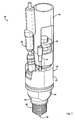
FIG. 2 is an enlarged perspective view of the ignition system of the present invention; -
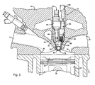
FIG. 3 is an enlarged partial cross-sectional side view of the ignition system of the present invention mounted in an internal combustion engine; -
FIG. 4 is an enlarged partial cross-sectional side view illustrating the injector and ignition device flush mounted in the pre-chamber of the ignition system; -
FIG. 5 is an elevational view of the upper portion of the combustion chamber illustrating the disposition of the ignition system relative to the intake and exhaust ports; -
FIG. 6 is a partial elevational view illustrating the orifices of the pre-chamber nozzle; -
FIG. 7 is a graph illustrating the ignition sequence for the ignition system of the present invention over one complete engine cycle; -
FIG. 8A is a graph illustrating combustion stability versus exhaust lambda (A) in a comparison of a spark ignition and turbulent jet ignition system of the present invention; -
FIG. 8B is a graph illustrating intake manifold absolute pressure as well as pumping mean effective pressure versus exhaust λ in a comparison of a spark ignition and turbulent jet ignition system of the present invention; -
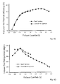
FIG. 8C is a graph of thermal efficiency versus exhaust λ in a comparison of a spark ignition and turbulent jet ignition system of the present invention; -
FIG. 8D is a graph illustrating exhaust port temperature versus exhaust λ in a comparison of a spark ignition and turbulent jet ignition system of the present invention; -
FIG. 8E is a graph illustrating normalized thermal efficiency relative to A equals one (stoichiometric operation) spark ignition versus exhaust λ in a comparison of a spark ignition and turbulent jet ignition system of the present invention; -
FIG. 8F is a graph illustrating engine out NOx emission versus exhaust A in a comparison of a spark ignition and turbulent jet ignition system of the present invention; -
FIG. 8G is a graph of engine out HC emissions versus exhaust λ in a comparison of a spark ignition and turbulent jet ignition system of the present invention; -
FIG. 8H is a graph illustrating engine out CO emissions versus exhaust A in a comparison of a spark ignition and turbulent jet ignition system of the present invention; -
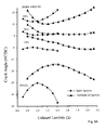
FIG. 9A is a graph of crank angles versus exhaust λ illustrating the burn angles in a comparison of a spark ignition and turbulent jet ignition system of the present invention; -
FIGS. 9B and9D are graphs illustrating 0-10% mass fraction burn versus exhaust λ in a comparison of a spark ignition and turbulent jet ignition system of the present invention; and -
FIGS. 9C and9E are graphs illustrating 10-90% mass fraction burn versus exhaust λ in a comparison of a spark ignition and turbulent jet ignition system of the present invention. - The present invention overcomes the disadvantages in the related art in an ignition system, generally indicated at 10 in
FIGS. 1-6 , where like numerals are used to designate like structure throughout the drawings. As shown inFIG. 1 , the present invention is particularly adapted for use in an internal combustion engine, generally indicated at 12. In this case, theignition system 10 of the present invention is illustrated in connection with asingle cylinder 14 of aninternal combustion engine 12. Those having ordinary skill in the art will appreciate that theengine 12 illustrated inFIG. 1 is but one of the many configurations of an internal combustion engine with which the present invention may be employed. By way of example, the present invention may be employed in a two-stroke or four-stroke engine. In addition, theignition system 10 may also be employed in a multiple-cylinder engine where the cylinders may be arranged in an inline, V-shaped, or flat manner, or any other manner commonly known in the art. The present invention may also be employed with a carburetor or fuel injected internal combustion engine having either port or direct injection of the fuel air charge into the main combustion chamber. - With continuing reference to
FIG. 1 , theinternal combustion engine 12 includes anengine block 16 having one ormore cylinders 14, and a cylinder head, generally indicated at 18, associated with theengine block 16. A piston, generally indicated at 20, is supported for repeated reciprocal movement in thecylinder 14. Together, thepiston 20,cylinder 14 andcylinder head 18 cooperate to define acombustion chamber 22. A connecting rod, generally indicated at 24, is secured to thepiston 20 through apiston pin 26. Acrankshaft 28 is associated with the connectingrod 24 and anoil pan 30 is associated with theengine block 16. Thecylinder head 18 defines anintake manifold 32 and anexhaust manifold 34. At least oneintake port 36 is defined in theintake manifold 32 and at least oneexhaust port 38 is defined in theexhaust manifold 34. The intake andexhaust ports cylinder 14 and theintake manifold 32 and theexhaust manifold 34, respectively. As illustrated in the view of the upper portion of the combustion chamber shown inFIG. 5 , in one embodiment, theinternal combustion engine 12 may include twointake ports 36 and twoexhaust ports 38. However, those having ordinary skill in the art will appreciate that theinternal combustion engine 10 may include any number of intake and exhaust ports. In addition, and in the embodiment illustrated inFIG. 1 , theinternal combustion engine 12 also includes afuel injector 40 mounted in theintake manifold 32 as a means of introducing the main fuel/air charge into thecombustion chamber 22 through theintake port 36. Similarly, products of combustion exit thecombustion chamber 22 through theexhaust port 38. Those having ordinary skill in the art will appreciate that theengine 12 may employ an injector that injects the main fuel charge directly into thecombustion chamber 22. Similarly, theengine 12 may also include a number of other conventional components that are commonly known in the art and will not be described in detail here. - Generally speaking, a fuel/air mixture is introduced into the
combustion chamber 22 via theintake port 36. This constitutes the main fuel charge. The fuel is combusted in thecombustion chamber 22 of thecylinder 14 to reciprocate thepiston 20, as will be described in greater detail below. Thepiston 20 drives the connectingrod 24 which drives thecrankshaft 28 causing it to rotate within theengine block 16. Specifically, the combustion pressure within thecylinder 14 drives thepiston 20 downward in a substantially linear motion. On the other hand, movement of thecrankshaft 28 drives the connectingrod 24 in a substantially rotational motion. The torque from thecrankshaft 28 may be utilized to drive any other component or related systems as is commonly known in the art. - Referring now to
FIGS. 2-6 , theignition system 10 of the present invention includes a housing, generally indicated at 42, that is defined in thecylinder head 18 of theinternal combustion engine 12. In one embodiment, thehousing 42 is a separate component that is operatively supported in thecylinder head 18 of the internal combustion engine. However, those having ordinary skill in the art will appreciate that thehousing 42 may be essentially defined in and form an integral part of thecylinder head 18. In any event, and in the embodiment illustrated in these figures, thecylinder head 18 may include a port 44 (FIG. 1 ) that receives thehousing 42 in a manner such that thehousing 42 is sealingly engaged with thecylinder head 18, as will be described in greater detail below. In addition, and as described in greater detail below, theport 44 may be of the substantial size and location that formerly received a standard sparkplug in aninternal combustion engine 12. This feature facilitates the retrofitting of existing engines with theignition system 10 of the present invention. As best shown inFIG. 3 , thehousing 42 defines asparkplug cavity portion 46, aninjector cavity portion 48, and a pre-chamber 50. Each of these components and their interrelationship with other components of theignition system 10 will be described in greater detail below. - The
housing 42 also includes a substantiallycylindrical portion 52 having anannular groove 54 disposed about thecylindrical portion 52. As best shown inFIG. 4 , an O-ring seal 56 is operatively received in thegroove 54 and adapted for sealing engagement with thecylinder head 18. In addition, thehousing 42 also includes a frustoconically-shapedportion 58 havingflats 60 formed thereon (FIG. 2 ). Theflats 60 cooperate with corresponding surfaces formed on thecylinder head 18 to stabilize and help fix thehousing 42 relative to the cylinder head 18 (FIG. 4 ). The frustoconically-shapedportion 58 terminates in ashoulder 62 that is juxtaposed to ashoulder 64 defined on thecylinder head 18. A sealingwasher 66 may be employed between these twoshoulders ignition system 10 within thecylinder head 18. Thehousing 42 also includes a terminal portion, generally indicated at 68, that includesexternal threads 70 andinternal threads 72. Theexternal threads 70 cooperate withthreads 74 formed on thecylinder head 18 to mount thehousing 42 therein. Those having ordinary skill in the art will appreciate that the ignition system may include any other appropriate seals or fastening mechanisms necessary to securely mount the ignition system in thecylinder head 18. - The pre-chamber 50 defines a
proximal portion 76 and a pre-chamber nozzle, generally indicated at 78, disposed spaced from theproximal portion 76 of the pre-chamber 50. As best shown inFIG. 4 , the pre-chamber 50 includes frustoconically-shapedsidewalls 80 that extend substantially from theproximal portion 76 to thepre-chamber nozzle 78 and defines a predetermined volume of the pre-chamber. Thepre-chamber nozzle 78 defines a longitudinal axis A and includes a plurality oforifices 82 disposed spaced from one another and providing fluid communication between the pre-chamber 50 and thecombustion chamber 22. In one embodiment, theorifices 82 have diameters in a range extending between 0.7 mm to 2.0 mm and are disposed about the longitudinal axis A in spaced relation with respect to each other. Moreover, and in one embodiment, the ratio of the orifice diameter to the pre-chamber volume is ideally in a range of 0.048 l/cm2 to 0.067 l/cm2. This ratio provides optimal minimum and maximum proportional component sizing to ensure effective penetration of radical turbulent jets into the main combustion chamber. This effective penetration in turn ensures optimal distribution of the ignition points resulting from the radical turbulent jets in the main combustion chamber thereby producing an effective and optimal combustion event as will be described in greater detail below. Thepre-chamber nozzle 78 is substantially cup shaped and includesexternal threads 84 that cooperate with theinternal threads 72 on theterminal portion 68 of thehousing 42 to mount thenozzle 78 thereon. - The
ignition system 10 also includes an ignition device, generally indicated at 86,' operatively received in thesparkplug cavity portion 46. Theignition device 86 includes anigniter portion 88 that substantially faces the pre-chamber 50. Likewise, aninjector 90 is operatively received in theinjector cavity portion 48. Theinjector 90 has anozzle 92 that substantially faces the pre-chamber 50. Theignition system 10 also includes a cooling tube 94 (FIG. 2 ) that provides fluid communication between a source of cooling fluid and thehousing 42. The cooling fluid may be either air, water, or any other fluid suitable for this purpose. However, those having ordinary skill in the art will appreciate that the coolingtube 94 and the provision for a cooling fluid is optional. In addition, theignition system 10 of the present invention may also employ a direct-injection installation sleeve 96 (FIG. 2 ) that surrounds theinjector 90 and stabilizes this component within theport 44 formed in thecylinder head 18. - In one embodiment, the
igniter portion 88 of theignition device 86 and thenozzle 92 of theinjector 90 are operatively supported in theproximal portion 76 of the pre-chamber 50 and disposed flush therewith such that theinjector 90 delivers a predetermined quantity of fuel into the pre-chamber 50. Theigniter portion 88 ignites the fuel in the pre-chamber 50. Once ignited, the fuel is forced through theorifices 82 of thepre-chamber nozzle 78 such that the flame is extinguished. Even though extinguished, the products of this pre-chamber combustion are disbursed through thecombustion chamber 22 so as to ignite the main fuel charge therein. - An ignition sequence employing the
ignition system 10 of the present invention is illustrated inFIG. 7 . The ignition sequence differs from conventional spark ignition fueling strategy in that there is an addition of pre-chamber fuel (approximately 2% of total energy) that is injected into the pre-chamber 50 via theinjector 90 and then ignited via theignition device 86. The pre-chamber fueling event is timed to end at approximately 50° before spark discharge. This ensures that a rich, plentiful mixture can be contained in the pre-chamber 50 which has been proven to chemically enhance the combustion process through the formation of active radicals. - The net effect of this phenomenon is to create a condition called "turbulent jet ignition." Turbulent jet ignition enables very fast burn rates due to the
ignition system 10 producing multiple, distributed ignition sites which consume the main charge rapidly and with minimum combustion variability. The relatively small size of theorifices 82 causes burning mixture to travel quickly through theorifices 82 which, as mentioned above, extinguishes the flame, but seeds thecombustion chamber 22 with partially combusted pre-chamber products. The pre-chamber combustion products entrain and ignite the main chamber charge through chemical, thermal, and turbulence effects some distance away from the pre-chamber 50, thus producing a distributed ignition system. - As noted above, the diameter of the
orifices 82 and the ratio of these diameters to the volume of the pre-chamber create a turbulent jet that penetrates deeper into the main charge. To this end, and as a means of avoiding impinging on the combustion chamber wall, in one preferred embodiment, the pre-chamber volume is relatively small. The fast burn rates allow for increased levels of dilution (lean burn and/or exhaust gas recirculation [EGR]) when compared to conventional spark ignition combustion. The high diluent fraction has enabled theignition system 10 of the present invention to record an 18% improvement in fuel consumption in a non-optimized engine when compared to conventional stoichiometric spark ignition combustion. However, it is projected that the present invention will realize as much as 30% improvement in fuel consumption in an engine that has an optimized combustion chamber. The efficiency improvements are due to a combination of combustion improvements, the near elimination of dissociation due to low combustion temperatures and reduced engine throttling. Additionally, the low temperature combustion has resulted in single digit parts per million (ppm) engine out (NOx) emissions with controllable levels of HC and CO emissions. -
FIGS. 8A-8H display relevant data derived from a single cylinder performance of the ignition system of the present invention including efficiency and emission comparisons between the present invention and standard spark ignition engines at fixed speed/load worldwide mapping point of 1.500 rev/min, 3.3 bar indicated net mean effective pressure (IMEPn). The spark ignition tests were conducted with gasoline which was port fuel injected, while the ignition system of the present invention utilized a mixture of approximately 98% gasoline and 2% propane. The gasoline was port fuel injected into the main chamber while the propane was directly injected into the pre-chamber. However, those having ordinary skill in the art will appreciate that any carbon based fuel can be used for the pre-chamber fuel. - More specifically,
FIG. 8A illustrates a combustion stability comparison up to 10% coefficient of variance in gross IMEP (CoV IMEPg) limit for both rich and lean conditions. The excess air results show that the ignition system of the present invention can operate up to an exhaust λ of 2.1 compared to only 1.4 for standard spark ignition systems. -
FIGS. 8B ,8C and 8D illustrate that the lower exhaust temperatures associated with high excess air rates may be near the lower temperature limits needed for efficient HC and CO oxidation. For equivalent exhaust A, the ignition system of the present invention produces exhaust temperatures that are, on average, 20° c to 40° c lower than spark ignition due to improved burn rates which minimize the host lost to the exhaust system. In addition, another major benefit of the ignition system of the present invention when compared to other low temperature combustion systems is that the combustion phasing can be manipulated by altering the pre-chamber spark discharge, thus providing a relatively simple method of combustion control for emissions and fuel economy. In addition, these figures illustrate that the engine dethrottling (increased manifold pressure while maintaining the same load) using the ignition system of the present invention operates at approximately 30 kPa higher MAP for the same load relative to stoichiometric spark ignition. This enables pumping losses to be reduced by approximately 0.3 BAR PMEP. -
FIG. 8E highlights the fact that the ignition system of the present invention, when employed in a single cylinder test facility, was able to produce an 18% fuel economy improvement when compared to stoichiometric spark ignition combustion. As noted above, the efficiency improvements are due to a combination of combustion improvements, the near elimination of dissociation due to the low combustion temperatures, and the reduced engine throttling. -
FIGS. 8F and8G illustrate engine out emission comparisons between the engine employing the ignition system of the present invention versus a standard spark ignition engine. As noted above, with the ignition system of the present invention, the internal combustion engine may employ high levels of excess air in the main fuel/air charge. High levels of excess air facilitates very low engine out NOx emissions due to the lower peak combustion temperatures.FIGS. 8F and8G illustrate that when the jet ignition system of the present invention is employed in an internal combustion engine, NOx emissions are reduced to almost zero levels (less than 10 ppm) for exhaust λ values greater than 1.8. This benefit associated with the ignition system of the present invention offers unique emission control opportunities and strategies that are not possible with spark ignition lean burn applications. The very low engine out NOx emissions past λ1.8 offer the possibility of eliminating the requirement for lean NOx after treatment for emission control. Rather, with the ignition system of the present invention engine out emissions can be controlled with a conventional three-way catalyst. -
FIGS. 8G and 8H provide comparisons for HC and CO emissions between the two systems. These two figures highlight the fact that there are significant increases displayed as the rich or lean dilution limit is reached for each combustion system. -
FIGS. 9A through 9E illustrate combustion burn comparisons for both spark ignition and an internal combustion engine employing the ignition system of the present invention with increasing dilution levels up to the combustion stability limit of 1,500 rev/min, 3.3 BAR IMEPn.FIG. 9A shows the spark discharge at 10%, 50%, and 90% burn angle locations. The burn angle represents the crank angle taken to burn 10-90% of the mass fraction (the fuel charge).FIGS. 9B and9D andFIGS. 9C and9E highlight the 0-10% and 10-90% mass fraction burn durations, respectively. - The data related to the burn angles illustrated in
FIGS. 9A illustrates that the ignition system of the present invention can tolerate considerably higher levels of dilution in the lean region. The distributed ignition caused by the turbulent jets that results from the ignition system of the present invention provides significantly increased burn rates, with fasfer flame initiation and hence propagation. It is also noted that the optimum 50% burn angle for both spark ignition and the ignition system of the present invention occurs in the 6-8° ATDC CA range across varying excess air dilution, despite a fundamentally different combustion process. Moreover, with the ignition system of the present invention, flame initiation occurs more rapidly than with spark ignition across the entire dilution range. - As best shown in
FIGS. 9B and9D , the excess air turbulent jet ignition 0-10% mass fraction burn results highlight that the flame initiation does not significantly change with increasing A, hovering constantly near 20-25° CA. This is due to the near constant mixture composition in the pre-chamber coupled with the distributed ignition sites provided by the jets and the high levels of chemically active species present in the combusting jets. In the case of an internal combustion engine employing spark ignition, it takes longer to initiate and stabilize the flame kernel after the spark discharge due to the reduced kernel growth associated with the diluted mixture. - The 10-90% mass fraction burn data shown in
FIGS. 9C and9E is indicative of the mixture's ability to propagate a flame. These results highlight the fact that in cases, flame propagation slows with increasing dilution due to reduced flame speeds associated with richer or leaner mixtures and lower combustion temperatures. As with the 0-10% burn duration, the 10-90% burn duration is shorter with the ignition system of the present invention than with spark ignition. The effect of the jet is less pronounced during the flame propagation part of the burn process as once the gasoline is ignited in the main chamber, the 10-90% burn data is more an indication of the multiple flame fronts propagating through the main fuel. However, the pre-chamber fuel continues to play a role during the main fuel combustion, as is evident by the shorter burn duration that occurs with the ignition system of the present invention relative to spark ignition. This is due to the enhanced combustion provided by the pre-chamber fuel and the high levels of active radicals produced in the combusting jet being maintained in the propagating flame. - Thus, the ignition system of the present invention achieves significantly improved operating parameters by employing a number of features that facilitate these results. For example, the relatively small pre-chamber volume of less than 2% of the clearance volume minimizes crevice volume, HC emissions, heat loss, surface-to-volume ratio effects and pre-chamber residual gas. The relatively small orifices 82 (having diameters in a range between 0.7 mm to 2.0 mm in size) that provide fluid communication between the pre-chamber 50 and the
main combustion chamber 22 allow flame quenching and penetration into thecombustion chamber 22. Combusted pre-chamber products (chemical, thermal, and turbulent effects) initiate main chamber combustion in multiple locations. In addition, the separately fueled pre-chamber 50 that employs a flush-mounted electronically controlleddirect injector 86 allows a rich mixture to be contained in the pre-chamber 50 while thecombustion chamber 22 is heavily diluted with excess air and/or EGR. The location of theinjector 86 at theproximal portion 76 of the pre-chamber 50 assists in scavenging the pre-chamber residuals and minimizing crevice volume. Where the internal combustion engine employs a separately fueledcombustion chamber 22 using an electronically controlled port fuel injection, for example, or direct injection, the present invention allows homogenous or stratified combustion chamber mixtures and thus HC/NOx emission control. In addition, the spark plug initiated pre-chamber combustion employing a flush mountedignition device 86 with electronically controlled ignition allows simple combustion phasing control. Moreover, theignition system 10 of the present invention utilizes commercially available fuel such as gasoline, propane or natural gas, for both the main and pre-chamber combustion cavities. - In this way, the ignition system of the present invention is capable of high-drive cycle (part load) fuel economy improvements that can reach up to 30% over baseline conventional spark ignition systems in an optimized engine, as well as high-peak thermal efficiencies (greater than 45%) at wide-open throttle (WOT). These engine performance enhancements are due to a combination of combustion improvements, reduced heat losses, the near elimination of disassociation due to the low combustion temperatures and reduced engine throttling at part-load. Additionally, the ignition system of the present invention facilitates low temperature combustion that is capable of near zero engine-out NOx emissions, while overcoming previous pre-chamber combustion hurdles of reduced peak performance (BMEP) and uncontrollable hydrocarbon (HC) and carbon monoxide (CO) when compared to conventional spark ignition combustion systems. Thus, the ignition system of the present invention can be utilized in engines with existing emission control systems found on conventional passenger vehicles (oxidation and three-way catalyst) to meet current and future emission regulations. Finally, the ignition system of the present invention also provides a "bolt on" fix capable of working with any spark ignition engine (pre- or post-production) with no base engine hardware modification required.
- The present invention has been described in an illustrative manner. It is to be understood that the terminology that has been used is intended to be in the nature of words of description rather than of limitation. Many modifications and variations of the present invention are possible in light of the above teachings. Therefore, the present invention may be practiced other than as specifically described.
Claims (6)
- Ignition system (10) for an internal combustion engine (12) having at least one combustion chamber (22), said ignition system comprising:a housing (42) defined in the cylinder head (18) of the internal combustion engine (12), said housing (42) defining a pre-chamber (50);an ignition device (86) supported in said housing (42) and having an igniter portion (88) that substantially faces said pre-chamber (50);an injector (90) supported in said housing (42) and having a nozzle (92) that substantially faces said pre-chamber (50);said pre-chamber (50) defining a proximal portion (76) and a pre-chamber nozzle (78) disposed spaced from said proximal portion (76) of said pre-chamber (50), said pre-chamber nozzle (78) including a plurality of orifices (82) having a diameter in a range between 0.7 mm to 2.0 mm and disposed spaced from one another and providing fluid communication between said pre-chamber (50) and the combustion chamber (22);said igniter portion (88) of said ignition device (86) and said nozzle (92) of said injector (90) operatively supported in the proximal portion of the pre-chamber (50) such that said injector (90) delivers a predetermined quantity of fuel into said pre-chamber (50), said igniter portion (88) ignites the fuel in said pre-chamber (50) such that the ignited fuel is forced through said orifices of said pre-chamber nozzle (78) and extinguished, but dispersed through the combustion chamber (22) so as to ignite the main fuel charge therein.
- Ignition system 10 as set forth in claim 1, wherein said pre-chamber (50) defines a predetermined volume and the ratio of the orifice (82) diameters to the pre-chamber volume is in a range between 0.0481/cm2 to 0.067 l/cm2.
- Ignition system 10 as set forth in claim 1 or 2, wherein said pre-chamber nozzle (78) defines a longitudinal axis A, said orifices (82) disposed about said longitudinal axis A in spaced relation with respect to each other.
- Internal combustion engine (12) comprising:an engine block (16) including at least one cylinder (14), a piston (20) supported for repeated reciprocal movement in said cylinder (14), and a cylinder head (18);said piston (20), cylinder (14) and cylinder head (18) cooperating to define at least one combustion chamber (22);said cylinder head (18) including at least one intake port (36) through which the main fuel air charge may flow into said combustion chamber (22) and at least one exhaust port (38) through which the products of combustion may exit said combustion chamber (22);said internal combustion engine (12) further including an ignition system (10), said ignition system (10) including a housing (42) operatively supported in the cylinder head (18) of the internal combustion engine (12), said housing (42) defining a pre-chamber (50);an ignition device (86) supported in said housing (42) and having an igniter portion (88) that substantially faces said pre-chamber (50);an injector (90) supported in said housing (42) and having a nozzle (92) that substantially faces said pre-chamber (50);said pre-chamber (50) defining a proximal portion (76) and a pre-chamber nozzle (78) disposed spaced from said proximal portion (76) of said pre-chamber (50), said pre-chamber nozzle (78) including a plurality of orifices (82) having a diameter in a range between 0.7 mm to 2.0 mm and disposed spaced from one another and providing fluid communication between said pre-chamber (50) and the combustion chamber (22);said igniter portion (88) of said ignition device (86) and said nozzle (92) of said injector (90) operatively supported in the proximal portion of the pre-chamber (50) such that said injector (90) delivers a predetermined quantity of fuel into said pre-chamber (50), said igniter portion (88) ignites the fuel in said pre-chamber (50) such that the ignited fuel is forced through said orifices (82) of said pre-chamber nozzle (78) and extinguished, but dispersed through the combustion chamber (22) so as to ignite the main fuel charge therein.
- Internal combustion engine (12) as set forth in claim 4, wherein said pre-chamber (50) defines a predetermined volume and the ratio of the orifice (82) diameters to the pre-chamber volume is in a range between 0.048 l/cm2 to 0.067 l/cm2.
- Internal combustion engine (12) as set forth in claim 4 or 5, wherein said pre-chamber nozzle (78) defines a longitudinal axis A, said orifices (82) disposed about said longitudinal axis A in spaced relation with respect to each other.
Applications Claiming Priority (1)
| Application Number | Priority Date | Filing Date | Title |
|---|---|---|---|
| US14/496,824 US9353674B2 (en) | 2010-11-01 | 2014-09-25 | Turbulent jet ignition pre-chamber combustion system for spark ignition engines |
Publications (3)
| Publication Number | Publication Date |
|---|---|
| EP3001008A1 true EP3001008A1 (en) | 2016-03-30 |
| EP3001008B1 EP3001008B1 (en) | 2021-06-02 |
| EP3001008B9 EP3001008B9 (en) | 2021-08-04 |
Family
ID=54140197
Family Applications (1)
| Application Number | Title | Priority Date | Filing Date |
|---|---|---|---|
| EP15002620.1A Active EP3001008B9 (en) | 2014-09-25 | 2015-09-07 | Turbulent jet ingnition pre-chamber combustion system for spark ignition engines |
Country Status (4)
| Country | Link |
|---|---|
| EP (1) | EP3001008B9 (en) |
| JP (1) | JP6329926B2 (en) |
| KR (1) | KR20160036478A (en) |
| CN (1) | CN106194395A (en) |
Cited By (6)
| Publication number | Priority date | Publication date | Assignee | Title |
|---|---|---|---|---|
| WO2019126838A1 (en) * | 2017-12-29 | 2019-07-04 | Avl List Gmbh | Spark plug |
| WO2020229775A1 (en) | 2019-05-13 | 2020-11-19 | Vianney Rabhi | Ignition insert with active prechamber |
| US11187141B2 (en) | 2019-05-13 | 2021-11-30 | Vianney Rabhi | Ignition insert with an active pre-chamber |
| CN113969825A (en) * | 2020-07-23 | 2022-01-25 | 广州汽车集团股份有限公司 | Split type precombustion chamber |
| CN115523062A (en) * | 2022-10-09 | 2022-12-27 | 一汽解放汽车有限公司 | Ammonia engine, vehicle and control method |
| US12378937B1 (en) | 2024-08-19 | 2025-08-05 | Fca Us Llc | Pre-ignition prevention using ion sense detection of exhaust stroke heat release for dual spark plug engines |
Families Citing this family (15)
| Publication number | Priority date | Publication date | Assignee | Title |
|---|---|---|---|---|
| EP3267008A1 (en) * | 2016-07-06 | 2018-01-10 | Mahle Powertrain LLC | Method for starting an internal combustion engine |
| US10174667B1 (en) * | 2017-11-17 | 2019-01-08 | Caterpillar Inc. | Prechamber ignition device for internal combustion engines and method |
| JP6927084B2 (en) * | 2018-03-02 | 2021-08-25 | トヨタ自動車株式会社 | Internal combustion engine |
| CN108730015B (en) * | 2018-05-22 | 2020-03-06 | 上海交通大学 | an engine with an auxiliary combustion chamber |
| US20200182217A1 (en) * | 2018-12-10 | 2020-06-11 | GM Global Technology Operations LLC | Combustion ignition devices for an internal combustion engine |
| CN110185534A (en) * | 2019-05-16 | 2019-08-30 | 天津大学 | A kind of spark assisted jet igniter motor |
| US11840954B2 (en) * | 2020-02-24 | 2023-12-12 | Mahle International Gmbh | Spark ignited engine with a pre-chamber, a prechamber and an adapter insert for the engine |
| AT523273B1 (en) * | 2020-03-16 | 2021-07-15 | Avl List Gmbh | CYLINDER HEAD |
| CN111927616A (en) * | 2020-08-03 | 2020-11-13 | 北京理工大学 | Jet combustion system for suppressing detonation |
| EP3981978A1 (en) * | 2020-10-09 | 2022-04-13 | MAHLE Powertrain, LLC | Method for operating a hydrogen fuelled combustion engine |
| CA3221165A1 (en) * | 2021-06-02 | 2022-12-08 | Jian Huang | Apparatuses and methods for fuel injection and/or ignition in an internal combustion engine |
| CN114294129A (en) * | 2022-01-26 | 2022-04-08 | 英国伦敦布鲁内尔大学 | Hydrogen jet ignition type combustion system of ammonia engine |
| CN116771486A (en) * | 2023-06-25 | 2023-09-19 | 天津大学 | Pre-combustion chamber igniter, methanol engine and cold start control method thereof |
| DE102024116569B4 (en) | 2024-06-13 | 2026-03-05 | Schaeffler Technologies AG & Co. KG | Internal combustion engine and methods for operating an internal combustion engine |
| WO2026018812A1 (en) * | 2024-07-18 | 2026-01-22 | 株式会社サステナブル・エンジン・リサーチセンター | Spark-ignition engine |
Citations (5)
| Publication number | Priority date | Publication date | Assignee | Title |
|---|---|---|---|---|
| US5522357A (en) * | 1993-04-20 | 1996-06-04 | Hitachi, Ltd. | Apparatus and method of fuel injection and ignition of internal combustion engine |
| JP2010150983A (en) * | 2008-12-24 | 2010-07-08 | Mitsubishi Heavy Ind Ltd | Gas engine including ignition plug |
| US20120103302A1 (en) * | 2010-11-01 | 2012-05-03 | William Attard | Turbulent jet ignition pre-chamber combustion system for spark ignition engines |
| WO2012091739A2 (en) * | 2010-12-31 | 2012-07-05 | Prometheus Applied Technologies, Llc | Prechamber ignition system |
| US20140144406A1 (en) * | 2012-11-27 | 2014-05-29 | Board Of Trustees Of Michigan State University | Internal combustion engine |
Family Cites Families (15)
| Publication number | Priority date | Publication date | Assignee | Title |
|---|---|---|---|---|
| JPS5831447B2 (en) * | 1973-08-27 | 1983-07-06 | 富士重工業株式会社 | Gasoline replacement |
| JPS5831448B2 (en) * | 1973-08-27 | 1983-07-06 | 富士重工業株式会社 | Torch Tenkashikininenkikan |
| GB2286633B (en) * | 1992-08-10 | 1997-11-12 | Mark Alan Cherry | Method and apparatus for compression timed ignition |
| US5533476A (en) * | 1995-06-14 | 1996-07-09 | Dresser-Rand Company | Walled precombustion chamber unit |
| US6016785A (en) * | 1998-10-01 | 2000-01-25 | Caterpillar Inc. | Pre-combustion chamber assembly and method |
| JP4086440B2 (en) * | 1999-12-24 | 2008-05-14 | 大阪瓦斯株式会社 | engine |
| JP2001227344A (en) * | 2000-02-14 | 2001-08-24 | Mitsubishi Heavy Ind Ltd | Nozzle hole structure of torch ignition-type gas engine |
| JP4368028B2 (en) * | 2000-03-22 | 2009-11-18 | 大阪瓦斯株式会社 | Torch ignition engine |
| US6513483B2 (en) * | 2001-02-07 | 2003-02-04 | Cooper Cameron Corporation | Pre-combustion chamber for an internal combustion engine |
| DE10217996A1 (en) * | 2002-04-23 | 2003-11-13 | Man B & W Diesel Ag | Self-igniting mixture-compressing internal combustion engine and method for its operation |
| JP4073315B2 (en) * | 2003-01-07 | 2008-04-09 | 大阪瓦斯株式会社 | Sub-chamber engine |
| JP2007255313A (en) * | 2006-03-23 | 2007-10-04 | Osaka Gas Co Ltd | Indirect injection engine |
| JP4609357B2 (en) * | 2006-03-24 | 2011-01-12 | 日産自動車株式会社 | Sub-chamber internal combustion engine |
| JP5060353B2 (en) * | 2008-03-14 | 2012-10-31 | 大阪瓦斯株式会社 | Sub-chamber engine |
| FI125706B (en) * | 2010-02-22 | 2016-01-15 | Wärtsilä Finland Oy | THE COMBUSTION ENGINE OF THE COMBUSTION ENGINE |
-
2015
- 2015-07-17 CN CN201510420924.1A patent/CN106194395A/en active Pending
- 2015-08-12 KR KR1020150113850A patent/KR20160036478A/en not_active Ceased
- 2015-08-18 JP JP2015161231A patent/JP6329926B2/en active Active
- 2015-09-07 EP EP15002620.1A patent/EP3001008B9/en active Active
Patent Citations (5)
| Publication number | Priority date | Publication date | Assignee | Title |
|---|---|---|---|---|
| US5522357A (en) * | 1993-04-20 | 1996-06-04 | Hitachi, Ltd. | Apparatus and method of fuel injection and ignition of internal combustion engine |
| JP2010150983A (en) * | 2008-12-24 | 2010-07-08 | Mitsubishi Heavy Ind Ltd | Gas engine including ignition plug |
| US20120103302A1 (en) * | 2010-11-01 | 2012-05-03 | William Attard | Turbulent jet ignition pre-chamber combustion system for spark ignition engines |
| WO2012091739A2 (en) * | 2010-12-31 | 2012-07-05 | Prometheus Applied Technologies, Llc | Prechamber ignition system |
| US20140144406A1 (en) * | 2012-11-27 | 2014-05-29 | Board Of Trustees Of Michigan State University | Internal combustion engine |
Cited By (9)
| Publication number | Priority date | Publication date | Assignee | Title |
|---|---|---|---|---|
| WO2019126838A1 (en) * | 2017-12-29 | 2019-07-04 | Avl List Gmbh | Spark plug |
| AT520987B1 (en) * | 2017-12-29 | 2022-03-15 | Avl List Gmbh | SPARK PLUG |
| WO2020229775A1 (en) | 2019-05-13 | 2020-11-19 | Vianney Rabhi | Ignition insert with active prechamber |
| FR3096078A1 (en) | 2019-05-13 | 2020-11-20 | Vianney Rabhi | ACTIVE PRE-CHAMBER IGNITION INSERT |
| FR3096079A1 (en) | 2019-05-13 | 2020-11-20 | Vianney Rabhi | ACTIVE PRE-CHAMBER IGNITION INSERT |
| US11187141B2 (en) | 2019-05-13 | 2021-11-30 | Vianney Rabhi | Ignition insert with an active pre-chamber |
| CN113969825A (en) * | 2020-07-23 | 2022-01-25 | 广州汽车集团股份有限公司 | Split type precombustion chamber |
| CN115523062A (en) * | 2022-10-09 | 2022-12-27 | 一汽解放汽车有限公司 | Ammonia engine, vehicle and control method |
| US12378937B1 (en) | 2024-08-19 | 2025-08-05 | Fca Us Llc | Pre-ignition prevention using ion sense detection of exhaust stroke heat release for dual spark plug engines |
Also Published As
| Publication number | Publication date |
|---|---|
| CN106194395A (en) | 2016-12-07 |
| JP6329926B2 (en) | 2018-05-23 |
| JP2016070270A (en) | 2016-05-09 |
| EP3001008B1 (en) | 2021-06-02 |
| EP3001008B9 (en) | 2021-08-04 |
| KR20160036478A (en) | 2016-04-04 |
Similar Documents
| Publication | Publication Date | Title |
|---|---|---|
| US9353674B2 (en) | Turbulent jet ignition pre-chamber combustion system for spark ignition engines | |
| EP3001008B9 (en) | Turbulent jet ingnition pre-chamber combustion system for spark ignition engines | |
| US8857405B2 (en) | Turbulent jet ignition pre-chamber combustion system for spark ignition engines | |
| US6032617A (en) | Dual fuel engine which ignites a homogeneous mixture of gaseous fuel, air, and pilot fuel | |
| CN107587930B (en) | Method for starting an internal combustion engine | |
| US6550430B2 (en) | Method of operating a dual fuel internal | |
| US8794212B2 (en) | Engine and method of operating engine | |
| US20140144406A1 (en) | Internal combustion engine | |
| JP5922830B1 (en) | Gas engine | |
| JP5765819B2 (en) | 2-cycle gas engine | |
| KR20220047528A (en) | Method for operating a hydrogen fuelled combustion engine | |
| JP2022107648A (en) | Dual fuel large diesel engine method of operation and dual fuel large diesel engine | |
| KR20220009355A (en) | Internal combustion engine | |
| US4126106A (en) | Mixed cycle internal combustion engine | |
| JP4073315B2 (en) | Sub-chamber engine | |
| JP4086440B2 (en) | engine | |
| Bureshaid et al. | Experimental studies of gasoline auxiliary fueled turbulent jet igniter at different speeds in single cylinder engine | |
| WO2020196207A1 (en) | Pre-chamber type internal combustion engine | |
| EP3037646B1 (en) | Method for operating internal combustion engines | |
| JP4145177B2 (en) | Engine and operation method thereof | |
| JP4007729B2 (en) | Engine and operation method thereof | |
| JP4719797B2 (en) | Internal combustion engine operation method | |
| JP2013234596A (en) | Two cycle divided chamber-type gas engine | |
| Davy et al. | The ultra lean burn partially stratified charge natural gas engine | |
| JP2016006325A (en) | Two-cycle gas engine and fuel gas injection system for two-cycle gas engine |
Legal Events
| Date | Code | Title | Description |
|---|---|---|---|
| PUAI | Public reference made under article 153(3) epc to a published international application that has entered the european phase |
Free format text: ORIGINAL CODE: 0009012 |
|
| AK | Designated contracting states |
Kind code of ref document: A1 Designated state(s): AL AT BE BG CH CY CZ DE DK EE ES FI FR GB GR HR HU IE IS IT LI LT LU LV MC MK MT NL NO PL PT RO RS SE SI SK SM TR |
|
| AX | Request for extension of the european patent |
Extension state: BA ME |
|
| 17P | Request for examination filed |
Effective date: 20160916 |
|
| RBV | Designated contracting states (corrected) |
Designated state(s): AL AT BE BG CH CY CZ DE DK EE ES FI FR GB GR HR HU IE IS IT LI LT LU LV MC MK MT NL NO PL PT RO RS SE SI SK SM TR |
|
| STAA | Information on the status of an ep patent application or granted ep patent |
Free format text: STATUS: EXAMINATION IS IN PROGRESS |
|
| 17Q | First examination report despatched |
Effective date: 20161117 |
|
| RIC1 | Information provided on ipc code assigned before grant |
Ipc: F02D 41/30 20060101ALI20210111BHEP Ipc: F02B 19/18 20060101ALI20210111BHEP Ipc: F02B 19/12 20060101ALI20210111BHEP Ipc: F02P 13/00 20060101ALI20210111BHEP Ipc: F02D 37/02 20060101ALI20210111BHEP Ipc: H01T 13/54 20060101ALI20210111BHEP Ipc: F02B 19/10 20060101AFI20210111BHEP |
|
| GRAP | Despatch of communication of intention to grant a patent |
Free format text: ORIGINAL CODE: EPIDOSNIGR1 |
|
| STAA | Information on the status of an ep patent application or granted ep patent |
Free format text: STATUS: GRANT OF PATENT IS INTENDED |
|
| INTG | Intention to grant announced |
Effective date: 20210222 |
|
| GRAS | Grant fee paid |
Free format text: ORIGINAL CODE: EPIDOSNIGR3 |
|
| GRAA | (expected) grant |
Free format text: ORIGINAL CODE: 0009210 |
|
| STAA | Information on the status of an ep patent application or granted ep patent |
Free format text: STATUS: THE PATENT HAS BEEN GRANTED |
|
| REG | Reference to a national code |
Ref country code: CH Ref legal event code: EP |
|
| AK | Designated contracting states |
Kind code of ref document: B1 Designated state(s): AL AT BE BG CH CY CZ DE DK EE ES FI FR GB GR HR HU IE IS IT LI LT LU LV MC MK MT NL NO PL PT RO RS SE SI SK SM TR |
|
| REG | Reference to a national code |
Ref country code: GB Ref legal event code: FG4D |
|
| REG | Reference to a national code |
Ref country code: AT Ref legal event code: REF Ref document number: 1398639 Country of ref document: AT Kind code of ref document: T Effective date: 20210615 |
|
| REG | Reference to a national code |
Ref country code: IE Ref legal event code: FG4D |
|
| REG | Reference to a national code |
Ref country code: DE Ref legal event code: R096 Ref document number: 602015069908 Country of ref document: DE |
|
| REG | Reference to a national code |
Ref country code: LT Ref legal event code: MG9D |
|
| PG25 | Lapsed in a contracting state [announced via postgrant information from national office to epo] |
Ref country code: HR Free format text: LAPSE BECAUSE OF FAILURE TO SUBMIT A TRANSLATION OF THE DESCRIPTION OR TO PAY THE FEE WITHIN THE PRESCRIBED TIME-LIMIT Effective date: 20210602 Ref country code: FI Free format text: LAPSE BECAUSE OF FAILURE TO SUBMIT A TRANSLATION OF THE DESCRIPTION OR TO PAY THE FEE WITHIN THE PRESCRIBED TIME-LIMIT Effective date: 20210602 Ref country code: LT Free format text: LAPSE BECAUSE OF FAILURE TO SUBMIT A TRANSLATION OF THE DESCRIPTION OR TO PAY THE FEE WITHIN THE PRESCRIBED TIME-LIMIT Effective date: 20210602 Ref country code: BG Free format text: LAPSE BECAUSE OF FAILURE TO SUBMIT A TRANSLATION OF THE DESCRIPTION OR TO PAY THE FEE WITHIN THE PRESCRIBED TIME-LIMIT Effective date: 20210902 |
|
| REG | Reference to a national code |
Ref country code: NL Ref legal event code: MP Effective date: 20210602 |
|
| REG | Reference to a national code |
Ref country code: AT Ref legal event code: MK05 Ref document number: 1398639 Country of ref document: AT Kind code of ref document: T Effective date: 20210602 |
|
| PG25 | Lapsed in a contracting state [announced via postgrant information from national office to epo] |
Ref country code: RS Free format text: LAPSE BECAUSE OF FAILURE TO SUBMIT A TRANSLATION OF THE DESCRIPTION OR TO PAY THE FEE WITHIN THE PRESCRIBED TIME-LIMIT Effective date: 20210602 Ref country code: SE Free format text: LAPSE BECAUSE OF FAILURE TO SUBMIT A TRANSLATION OF THE DESCRIPTION OR TO PAY THE FEE WITHIN THE PRESCRIBED TIME-LIMIT Effective date: 20210602 Ref country code: NO Free format text: LAPSE BECAUSE OF FAILURE TO SUBMIT A TRANSLATION OF THE DESCRIPTION OR TO PAY THE FEE WITHIN THE PRESCRIBED TIME-LIMIT Effective date: 20210902 Ref country code: PL Free format text: LAPSE BECAUSE OF FAILURE TO SUBMIT A TRANSLATION OF THE DESCRIPTION OR TO PAY THE FEE WITHIN THE PRESCRIBED TIME-LIMIT Effective date: 20210602 Ref country code: GR Free format text: LAPSE BECAUSE OF FAILURE TO SUBMIT A TRANSLATION OF THE DESCRIPTION OR TO PAY THE FEE WITHIN THE PRESCRIBED TIME-LIMIT Effective date: 20210903 Ref country code: LV Free format text: LAPSE BECAUSE OF FAILURE TO SUBMIT A TRANSLATION OF THE DESCRIPTION OR TO PAY THE FEE WITHIN THE PRESCRIBED TIME-LIMIT Effective date: 20210602 |
|
| PG25 | Lapsed in a contracting state [announced via postgrant information from national office to epo] |
Ref country code: AT Free format text: LAPSE BECAUSE OF FAILURE TO SUBMIT A TRANSLATION OF THE DESCRIPTION OR TO PAY THE FEE WITHIN THE PRESCRIBED TIME-LIMIT Effective date: 20210602 Ref country code: ES Free format text: LAPSE BECAUSE OF FAILURE TO SUBMIT A TRANSLATION OF THE DESCRIPTION OR TO PAY THE FEE WITHIN THE PRESCRIBED TIME-LIMIT Effective date: 20210602 Ref country code: RO Free format text: LAPSE BECAUSE OF FAILURE TO SUBMIT A TRANSLATION OF THE DESCRIPTION OR TO PAY THE FEE WITHIN THE PRESCRIBED TIME-LIMIT Effective date: 20210602 Ref country code: PT Free format text: LAPSE BECAUSE OF FAILURE TO SUBMIT A TRANSLATION OF THE DESCRIPTION OR TO PAY THE FEE WITHIN THE PRESCRIBED TIME-LIMIT Effective date: 20211004 Ref country code: NL Free format text: LAPSE BECAUSE OF FAILURE TO SUBMIT A TRANSLATION OF THE DESCRIPTION OR TO PAY THE FEE WITHIN THE PRESCRIBED TIME-LIMIT Effective date: 20210602 Ref country code: CZ Free format text: LAPSE BECAUSE OF FAILURE TO SUBMIT A TRANSLATION OF THE DESCRIPTION OR TO PAY THE FEE WITHIN THE PRESCRIBED TIME-LIMIT Effective date: 20210602 Ref country code: EE Free format text: LAPSE BECAUSE OF FAILURE TO SUBMIT A TRANSLATION OF THE DESCRIPTION OR TO PAY THE FEE WITHIN THE PRESCRIBED TIME-LIMIT Effective date: 20210602 Ref country code: SM Free format text: LAPSE BECAUSE OF FAILURE TO SUBMIT A TRANSLATION OF THE DESCRIPTION OR TO PAY THE FEE WITHIN THE PRESCRIBED TIME-LIMIT Effective date: 20210602 Ref country code: SK Free format text: LAPSE BECAUSE OF FAILURE TO SUBMIT A TRANSLATION OF THE DESCRIPTION OR TO PAY THE FEE WITHIN THE PRESCRIBED TIME-LIMIT Effective date: 20210602 |
|
| REG | Reference to a national code |
Ref country code: DE Ref legal event code: R097 Ref document number: 602015069908 Country of ref document: DE |
|
| PLBE | No opposition filed within time limit |
Free format text: ORIGINAL CODE: 0009261 |
|
| STAA | Information on the status of an ep patent application or granted ep patent |
Free format text: STATUS: NO OPPOSITION FILED WITHIN TIME LIMIT |
|
| PG25 | Lapsed in a contracting state [announced via postgrant information from national office to epo] |
Ref country code: DK Free format text: LAPSE BECAUSE OF FAILURE TO SUBMIT A TRANSLATION OF THE DESCRIPTION OR TO PAY THE FEE WITHIN THE PRESCRIBED TIME-LIMIT Effective date: 20210602 |
|
| 26N | No opposition filed |
Effective date: 20220303 |
|
| REG | Reference to a national code |
Ref country code: CH Ref legal event code: PL |
|
| REG | Reference to a national code |
Ref country code: BE Ref legal event code: MM Effective date: 20210930 |
|
| PG25 | Lapsed in a contracting state [announced via postgrant information from national office to epo] |
Ref country code: MC Free format text: LAPSE BECAUSE OF FAILURE TO SUBMIT A TRANSLATION OF THE DESCRIPTION OR TO PAY THE FEE WITHIN THE PRESCRIBED TIME-LIMIT Effective date: 20210602 Ref country code: AL Free format text: LAPSE BECAUSE OF FAILURE TO SUBMIT A TRANSLATION OF THE DESCRIPTION OR TO PAY THE FEE WITHIN THE PRESCRIBED TIME-LIMIT Effective date: 20210602 |
|
| PG25 | Lapsed in a contracting state [announced via postgrant information from national office to epo] |
Ref country code: LU Free format text: LAPSE BECAUSE OF NON-PAYMENT OF DUE FEES Effective date: 20210907 Ref country code: IE Free format text: LAPSE BECAUSE OF NON-PAYMENT OF DUE FEES Effective date: 20210907 Ref country code: BE Free format text: LAPSE BECAUSE OF NON-PAYMENT OF DUE FEES Effective date: 20210930 |
|
| PG25 | Lapsed in a contracting state [announced via postgrant information from national office to epo] |
Ref country code: LI Free format text: LAPSE BECAUSE OF NON-PAYMENT OF DUE FEES Effective date: 20210930 Ref country code: CH Free format text: LAPSE BECAUSE OF NON-PAYMENT OF DUE FEES Effective date: 20210930 |
|
| PG25 | Lapsed in a contracting state [announced via postgrant information from national office to epo] |
Ref country code: HU Free format text: LAPSE BECAUSE OF FAILURE TO SUBMIT A TRANSLATION OF THE DESCRIPTION OR TO PAY THE FEE WITHIN THE PRESCRIBED TIME-LIMIT; INVALID AB INITIO Effective date: 20150907 |
|
| PG25 | Lapsed in a contracting state [announced via postgrant information from national office to epo] |
Ref country code: CY Free format text: LAPSE BECAUSE OF FAILURE TO SUBMIT A TRANSLATION OF THE DESCRIPTION OR TO PAY THE FEE WITHIN THE PRESCRIBED TIME-LIMIT Effective date: 20210602 |
|
| P01 | Opt-out of the competence of the unified patent court (upc) registered |
Effective date: 20230607 |
|
| REG | Reference to a national code |
Ref country code: DE Ref legal event code: R081 Ref document number: 602015069908 Country of ref document: DE Owner name: MAHLE INTERNATIONAL GMBH, DE Free format text: FORMER OWNER: MAHLE POWERTRAIN LLC, FARMINGTON HILLS, MI, US |
|
| REG | Reference to a national code |
Ref country code: GB Ref legal event code: 732E Free format text: REGISTERED BETWEEN 20230928 AND 20231004 |
|
| PG25 | Lapsed in a contracting state [announced via postgrant information from national office to epo] |
Ref country code: MK Free format text: LAPSE BECAUSE OF FAILURE TO SUBMIT A TRANSLATION OF THE DESCRIPTION OR TO PAY THE FEE WITHIN THE PRESCRIBED TIME-LIMIT Effective date: 20210602 |
|
| PG25 | Lapsed in a contracting state [announced via postgrant information from national office to epo] |
Ref country code: MT Free format text: LAPSE BECAUSE OF FAILURE TO SUBMIT A TRANSLATION OF THE DESCRIPTION OR TO PAY THE FEE WITHIN THE PRESCRIBED TIME-LIMIT Effective date: 20210602 |
|
| PGFP | Annual fee paid to national office [announced via postgrant information from national office to epo] |
Ref country code: DE Payment date: 20250919 Year of fee payment: 11 |
|
| PGFP | Annual fee paid to national office [announced via postgrant information from national office to epo] |
Ref country code: IT Payment date: 20250923 Year of fee payment: 11 |
|
| PGFP | Annual fee paid to national office [announced via postgrant information from national office to epo] |
Ref country code: GB Payment date: 20250919 Year of fee payment: 11 |
|
| PGFP | Annual fee paid to national office [announced via postgrant information from national office to epo] |
Ref country code: FR Payment date: 20250922 Year of fee payment: 11 |
|
| PG25 | Lapsed in a contracting state [announced via postgrant information from national office to epo] |
Ref country code: TR Free format text: LAPSE BECAUSE OF FAILURE TO SUBMIT A TRANSLATION OF THE DESCRIPTION OR TO PAY THE FEE WITHIN THE PRESCRIBED TIME-LIMIT Effective date: 20210602 |