EP3000935B1 - Protective structure - Google Patents
Protective structure Download PDFInfo
- Publication number
- EP3000935B1 EP3000935B1 EP14186892.7A EP14186892A EP3000935B1 EP 3000935 B1 EP3000935 B1 EP 3000935B1 EP 14186892 A EP14186892 A EP 14186892A EP 3000935 B1 EP3000935 B1 EP 3000935B1
- Authority
- EP
- European Patent Office
- Prior art keywords
- control structure
- structure according
- protective control
- retaining
- base plate
- Prior art date
- Legal status (The legal status is an assumption and is not a legal conclusion. Google has not performed a legal analysis and makes no representation as to the accuracy of the status listed.)
- Active
Links
- 230000001681 protective effect Effects 0.000 title claims description 25
- 241000251468 Actinopterygii Species 0.000 claims description 4
- 239000013585 weight reducing agent Substances 0.000 claims description 2
- 230000000717 retained effect Effects 0.000 claims 1
- 239000000969 carrier Substances 0.000 description 12
- 230000004888 barrier function Effects 0.000 description 6
- 239000000725 suspension Substances 0.000 description 5
- 239000011435 rock Substances 0.000 description 4
- 210000001015 abdomen Anatomy 0.000 description 3
- 230000001419 dependent effect Effects 0.000 description 1
- 238000011161 development Methods 0.000 description 1
- 230000018109 developmental process Effects 0.000 description 1
- 230000003116 impacting effect Effects 0.000 description 1
- 239000007788 liquid Substances 0.000 description 1
- 230000021715 photosynthesis, light harvesting Effects 0.000 description 1
- 230000000452 restraining effect Effects 0.000 description 1
- 239000004575 stone Substances 0.000 description 1
- 239000000758 substrate Substances 0.000 description 1
- 230000001502 supplementing effect Effects 0.000 description 1
Images


Classifications
-
- E—FIXED CONSTRUCTIONS
- E01—CONSTRUCTION OF ROADS, RAILWAYS, OR BRIDGES
- E01F—ADDITIONAL WORK, SUCH AS EQUIPPING ROADS OR THE CONSTRUCTION OF PLATFORMS, HELICOPTER LANDING STAGES, SIGNS, SNOW FENCES, OR THE LIKE
- E01F7/00—Devices affording protection against snow, sand drifts, side-wind effects, snowslides, avalanches or falling rocks; Anti-dazzle arrangements ; Sight-screens for roads, e.g. to mask accident site
- E01F7/04—Devices affording protection against snowslides, avalanches or falling rocks, e.g. avalanche preventing structures, galleries
- E01F7/045—Devices specially adapted for protecting against falling rocks, e.g. galleries, nets, rock traps
Definitions
- the invention relates to a protective barrier according to the preamble of claim 1.
- Such Schutzverbauung is for example from the DE-A-1 057 157 or the US-A-2014/0196382 known.
- a protective barrier which has at least one carrier, but usually a plurality of spaced-apart carriers.
- the carriers may e.g. be arranged on a mountain slope to be built.
- a safety net is led.
- Each of the carriers is arranged on an associated base plate, with the aid of which the carriers are fixed to the ground, using anchors and / or micropiles.
- At least one of the carriers is fixed to its associated bottom plate via a ball joint.
- the ball joint has for this purpose a pan and a guided in this ball, which is secured in position in the pan by means of a retaining device.
- the advantage is first achieved that the carrier relative to the bottom plate by pivoting the ball joint can be tilted and beyond also turned around its vertical axis against the bottom plate. This gives the advantage that the carrier optimally to the conditions of the place of use with regard to their
- Alignment can be adjusted. This, in turn, provides the advantage of increasing the efficiency of the energy dissipation in articles impacting the safety net of the protective barrier according to the invention.
- a retaining device provides the advantage that it can be prevented that the ball is moved out of the pan when an object strikes the safety net and accordingly act forces on the carrier or carriers, which could cause such a moving out of the ball from the pan ,
- the bottom plate can be weight-optimized by the attachment of recesses in the bottom plate itself and / or the pan, if it is attached to the bottom plate.
- brackets on the bottom plate through which support rods can be inserted therethrough, so that the bottom plate can be easily transported to its place of use.
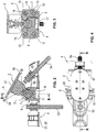
- Fig. 1 is schematically illustrated a protective enclosure 1 according to the invention, wherein Fig. 1 a page view shows.
- the Schutzverbauung 1 has a so-called. "Support structure", which is usually formed by a plurality of supports 2 (also: supports), the anchor 53 and 54 in the ground or ground U of a slope H, as shown in FIG Example trap shown can be fixed.
- a plurality of such carriers are provided, of which in Fig. 1 Representative of all the carrier carrier 2 is shown visible. If a plurality of carriers 2 are provided, they are positioned next to each other on the slope H at selectable intervals from one another.
- a plurality of spaced-apart carriers 2 are provided.
- the Schutzverbauung 1 further comprises a network or safety net 3, which in the region of a support head 47 of in Fig. 1 shown support 2 is guided over a support cable assembly 44, wherein it is possible that the support cable assembly 44 comprises one or two upper support cables.
- a lower suspension cable arrangement 46 is provided, which in turn may comprise one or two lower suspension cables.
- the center cable assembly 45 may include one or more center ropes, as in the example four center ropes.
- the middle cable arrangement 45 or its middle ropes can be guided on the support 2 via guide devices.
- the guide means may be formed here as a shackle, for example.
- an upper guy rope or mountain-side restraining rope 49 is provided.
- the upper guy rope 49 holds the column head 47 of the carrier 2 via a fastening device 52 (rock anchor / ground anchor / anchor) in the underground U of the slope H.
- a brake element 51 is also provided in the guy rope 49.
- a bottom plate 4 is provided on which the in Fig. 1 visible support 2 is mounted. If a plurality of such carrier 2 is provided, each carrier 2 is provided with an associated bottom plate 4 and fixed in the substrate U via this.
- the carrier 2 is fixed to its associated bottom plate 4 via a ball joint 5, which will be described below with reference to FIGS Fig. 2 to 6 will be explained in detail.
- the ball joint 5 a pan 6, which is fixed in the example case to the bottom plate 4, for example by a weld.
- the ball joint 5 further comprises a ball 7, which is connected in the example case via a connecting piece 57 with the carrier 2, the in Fig. 2 symbolized by its lower end plate.
- the ball 7 is further arranged in a ball receiving space 56 of the pan 6, so that the carrier 2, as in Fig. 2 can be pivoted about the center M of the ball 7, as well as about its vertical axis A can be rotated.
- the bottom plate of the carrier 2 is provided with two drainage holes 58 and 59, which serve to drain into the carrier 2 liquid, if it is a hollow carrier, run off.
- FIGS. 2 and 3 in that a recess 17, which serves to save weight, is arranged in the base plate 4 or in the pan 6. As Fig. 4 shows, more edge-side recesses 60 and 61 are provided, which also serve to reduce weight of the bottom plate 4.
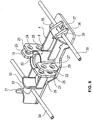
- the protection structure 1 is further provided with a retaining device 8, the structure of which is particularly apparent from the illustration of Fig. 3 . 5 and 6 which is referred to below.
- the retaining device 8 has two L-shaped retaining fingers or retaining levers, which are rotatably supported by pivot pins 11 and 14, respectively.
- the pivot pins 11, 14 for this purpose inserted through recesses 25 and 28 and 29 in retaining plates 19, 20 and 21, 22 and pass through a correspondingly aligned recess in the respective retaining fingers 9 and 10, so that this retaining finger, like in Fig. 5 clarified, from an open position (holding finger 9) in a holding position (holding finger 10) can be pivoted.
- the holding plates 19 to 22 are each fixed to the bottom plate 4, preferably welded.
- two half-shells 31 and 32 On the opposite side of the bottom plate 4, two half-shells 31 and 32, with their curvatures facing each other, arranged, preferably welded.
- the two half-shells 31 and 32 are connected to each other via a connecting piece 33, which is arranged at a selectable distance from the bottom plate 4, so that a through-passage 62 between the connecting piece 33 and the bottom plate 4 is limited.
- a support rod 34 are inserted therethrough.
- Fig. 6 shows accordingly the transport state of the bottom plate 4, whose weight can be about 80 kg, so that the provision of support rods 34, 39 greatly facilitates the transport for fitters.
- a particularly preferred embodiment of a carrier 40 is shown, which is a so-called fish belly carrier.
- Such fish belly carrier 40 have bent executed, from the top view of Fig. 7 apparent support tubes 41 and 42 which are interconnected via a truss structure 43.
- truss structure 43 is only one example of a possible arrangement of a plurality of angularly arranged truss struts, which may, however, also be designed differently than in Fig. 7 shown.
- a carrier in addition to the particularly preferred fish belly carriers 40 as shown in the Fig. 7 already known carriers, such as double-T-carrier used.
Description
Die Erfindung betrifft eine Schutzverbauung gemäß dem Oberbegriff des Anspruches 1.The invention relates to a protective barrier according to the preamble of claim 1.
Eine derartige Schutzverbauung ist beispielsweise aus der
Gegenüber der gattungsgemäßen Schutzverbauung ist es Aufgabe der vorliegenden Erfindung, eine Schutzverbauung der im Oberbegriff des Anspruchs 1 angegebenen Art zu schaffen, die effizienten Energieabbau gegen Steinschlag, Holzschlag, Lawinen oder ähnlichem möglich macht, und die auf einfache Art und Weise zu montieren und demontieren ist.Compared with the generic Schutzverbauung, it is an object of the present invention to provide a Schutzverbauung specified in the preamble of claim 1 way, the efficient energy reduction against stone chipping, felling, avalanches or the like makes possible, and to assemble and disassemble in a simple manner ,
Die Lösung dieser Aufgabe erfolgt durch die Merkmale des Anspruchs 1.The solution of this object is achieved by the features of claim 1.
Dementsprechend wird erfindungsgemäß eine Schutzverbauung geschaffen, die zumindestens einen Träger, üblicherweise jedoch eine Mehrzahl von beabstandet zueinander angeordneten Trägern aufweist. Die Träger können z.B. an einem zu verbauenden Berghang angeordnet werden. An den Trägern ist ein Fangnetz geführt. Jeder der Träger ist auf einer zugeordneten Bodenplatte angeordnet, mit deren Hilfe die Träger am Untergrund fixiert werden, wozu Anker und/oder Mikropfähle verwendet werden.Accordingly, according to the invention a protective barrier is provided, which has at least one carrier, but usually a plurality of spaced-apart carriers. The carriers may e.g. be arranged on a mountain slope to be built. At the carriers a safety net is led. Each of the carriers is arranged on an associated base plate, with the aid of which the carriers are fixed to the ground, using anchors and / or micropiles.
Erfindungsgemäß ist zumindest einer der Träger, üblicherweise jedoch jeder Träger, an seiner zugeordneten Bodenplatte über ein Kugelgelenk fixiert. Das Kugelgelenk weist hierfür eine Pfanne und eine in dieser geführte Kugel auf, die mittels einer Rückhaltevorrichtung in der Pfanne lagegesichert ist.According to the invention, at least one of the carriers, but usually each carrier, is fixed to its associated bottom plate via a ball joint. The ball joint has for this purpose a pan and a guided in this ball, which is secured in position in the pan by means of a retaining device.
Dadurch wird zunächst der Vorteil erreicht, dass der Träger gegenüber der Bodenplatte durch Verschwenken des Kugelgelenks geneigt werden kann und darüber hinaus um seine Hochachse auch gegenüber der Bodenplatte gedreht werde kann. Dies ergibt den Vorteil, dass die Träger optimal an die Gegebenheiten des Einsatzortes hinsichtlich ihrerAs a result, the advantage is first achieved that the carrier relative to the bottom plate by pivoting the ball joint can be tilted and beyond also turned around its vertical axis against the bottom plate. This gives the advantage that the carrier optimally to the conditions of the place of use with regard to their
Ausrichtung angepasst werden können. Dies wiederum ergibt den Vorteil einer Steigerung der Effizienz des Energieabbaues bei in das Fangnetz der erfindungsgemäßen Schutzverbauung einschlagenden Gegenständen.Alignment can be adjusted. This, in turn, provides the advantage of increasing the efficiency of the energy dissipation in articles impacting the safety net of the protective barrier according to the invention.
Das Vorsehen einer Rückhaltevorrichtung ergibt den Vorteil, dass verhindert werden kann, dass die Kugel aus der Pfanne herausbewegt wird, wenn ein Gegenstand in das Fangnetz einschlägt und dementsprechend Kräfte auf den oder die Träger einwirken, die ein derartiges Herausbewegen der Kugel aus der Pfanne bewirken könnten.The provision of a retaining device provides the advantage that it can be prevented that the ball is moved out of the pan when an object strikes the safety net and accordingly act forces on the carrier or carriers, which could cause such a moving out of the ball from the pan ,
Erfindungsgemäß ist es möglich, die Kugel des Kugelgelenks entweder am Träger oder der Bodenplatte und dementsprechend die Pfanne entweder an der Bodenplatte oder am Träger anzubringen.According to the invention it is possible to attach the ball of the ball joint either on the carrier or the bottom plate and, accordingly, the pan either on the bottom plate or on the carrier.
Die Unteransprüche zeigen bevorzugte Weiterbildungen der Erfindung.The dependent claims show preferred developments of the invention.
Insbesondere ist hervorzuheben, dass die Bodenplatte durch das Anbringen von Ausnehmungen in der Bodenplatte selber und/oder der Pfanne, falls diese an der Bodenplatte angebracht ist, gewichtsoptimiert werden kann.In particular, it should be emphasized that the bottom plate can be weight-optimized by the attachment of recesses in the bottom plate itself and / or the pan, if it is attached to the bottom plate.
Ferner ist es möglich, Halterungen auf der Bodenplatte vorzusehen, durch die hindurch Tragstangen hindurchgesteckt werden können, damit die Bodenplatte leicht an ihren Einsatzort transportiert werden kann.Further, it is possible to provide brackets on the bottom plate, through which support rods can be inserted therethrough, so that the bottom plate can be easily transported to its place of use.
Weitere Einzelheiten, Merkmale und Vorteile der Erfindung ergeben sich aus nachfolgender Beschreibung von Ausführungsbeispielen anhand der Zeichnung. Darin zeigt:
- Fig. 1
- eine schematisch leicht vereinfachte Seitenansicht einer erfindungsgemäßen Schutzverbauung,
- Fig. 2
- eine Schnittdarstellung einer Bodenplatte mit montiertem Drehgelenk,
- Fig. 3
- eine Schnittdarstellung der Bodenplatte gemäß
Fig. 2 aus einer um 90° gedrehten Ansichtsrichtung, - Fig. 4
- eine Draufsicht auf die Bodenplatte gemäß
Fig. 2 , - Fig. 5
- eine perspektivische Draufsicht auf die Bodenplatte,
- Fig. 6
- eine der
Fig. 5 entsprechende Darstellung der Bodenplatte mit montierten Tragstangen, und - Fig. 7
- eine schematisch leicht vereinfachte Darstellung einer besonders bevorzugten Ausführungsform eines Trägers der erfindungsgemäßen Schutzverbauung.
- Fig. 1
- a schematically slightly simplified side view of a protective enclosure according to the invention,
- Fig. 2
- a sectional view of a bottom plate with mounted swivel joint,
- Fig. 3
- a sectional view of the bottom plate according to
Fig. 2 from a 90 ° rotated viewing direction, - Fig. 4
- a plan view of the bottom plate according to
Fig. 2 . - Fig. 5
- a perspective top view of the bottom plate,
- Fig. 6
- one of the
Fig. 5 corresponding representation of the bottom plate with mounted support rods, and - Fig. 7
- a schematically slightly simplified representation of a particularly preferred embodiment of a support of the protective barrier according to the invention.
In
Die Schutzverbauung 1 weist eine sog. "Stützstruktur" auf, die in der Regel von einer Mehrzahl von Trägern 2 (auch: Stützen) gebildet wird, die über Anker 53 und 54 im Untergrund bzw. Boden U eines Hanges H, wie dies im dargestellten Beispielsfalle gezeigt ist, fixiert werden können. Je nach Verbaulänge der Schutzverbauung 1 sind eine Mehrzahl derartiger Träger vorgesehen, von denen in
Die Schutzverbauung 1 weist weiterhin ein Netz bzw. Fangnetz 3 auf, das im Bereich eines Stützenkopfes 47 des in
Im Bereich des Stützenfußes 55 des Trägers 2 ist eine untere Tragseilanordnung 46 vorgesehen, die wiederum ein oder zwei untere Tragseile umfassen kann.In the area of the
Zwischen der oberen Tragseilanordnung 44 und der unteren Tragseilanordnung 46 ist im dargestellten, besonders bevorzugten Beispielsfall eine Mittelseilanordnung 45 vorgesehen. Die Mittelseilanordnung 45 kann ein oder mehrere Mittelseile aufweisen, wie im Beispielsfalle vier Mittelseile. Die Mittelseilanordnung 45 bzw. ihre Mittelseile können hierbei über Führungseinrichtungen am Träger 2 geführt sein. Die Führungseinrichtungen können hierbei beispielsweise auch als Schäkel ausgebildet sein.Between the upper carrying
Ferner verdeutlicht die Ausführungsform der Schutzverbauung 1 gemäß
Wie
Erfindungsgemäß ist der Träger 2 an seiner zugeordneten Bodenplatte 4 über ein Kugelgelenk 5 fixiert, was nachfolgend unter Bezugnahme auf die
Hierzu wird nachfolgend zunächst auf die Darstellungen der
Wie sich insbesondere aus den
Die Bodenplatte des Trägers 2 ist mit zwei Ablaufbohrungen 58 und 59 versehen, die dazu dienen, dass in den Träger 2 eingedrungene Flüssigkeit, falls es sich um einen Hohlträger handelt, ablaufen kann.The bottom plate of the
Ferner verdeutlichen die
Die erfindungsgemäße Schutzverbauung 1 ist ferner mit einer Rückhaltevorrichtung 8 versehen, deren Aufbau sich insbesondere aus der Darstellung der
Dementsprechend weist die Rückhaltevorrichtung 8 zwei L-förmige Rückhaltefinger bzw. Rückhaltehebel auf, die über Schwenkbolzen 11 bzw. 14 drehbar gehalten sind. Wie vor allem die Darstellung der
Zum Fixieren der Haltefinger 9, 10 in der Halteposition sind Sicherungsbolzen 12 bzw. 13 mit zugeordneten Handhaben 18 bzw. 18' vorgesehen, die durch zugeordnete Ausnehmungen 23, 24, 26, 27 in den Halteplatten 19 bis 22 und dementsprechend angeordnete Ausnehmungen in den Rückhaltefingern 9 und 10 gesteckt werden können, wie dies am Beispiel des Haltefingers 10 in
Die Halteplatten 19 bis 22 sind jeweils auf der Bodenplatte 4 fixiert, vorzugsweise verschweißt.The holding
In der in
Wie ferner die Darstellung der
Auf der gegenüberliegenden Seite sind auf der Bodenplatte 4 zwei Halbschalen 31 und 32, mit ihren Wölbungen aufeinander zugerichtet, angeordnet, vorzugsweise verschweißt. Die beiden Halbschalen 31 und 32 sind über ein Verbindungsstück 33 miteinander verbunden, das in einem wählbaren Abstand zur Bodenplatte 4 angeordnet ist, so dass eine Durchgangsausnehmung 62 zwischen dem Verbindungsstück 33 und der Bodenplatte 4 begrenzt wird.On the opposite side of the
Wie
Es ist ferner möglich, eine weitere Tragstange 39 durch die fluchtend angeordneten Durchgangsausnehmungen 37 und 38 der Trapezplatten 35 bzw. 36 hindurchzustecken, wie dies
In
Als Träger können neben den besonders bevorzugten Fischbauchträgern 40 gemäß der Darstellung der
Auch andere grundsätzlich für Schutzverbauungen geeignete Trägerkonstruktionen sind bei der erfindungsgemäßen Schutzverbauung möglich.Other support structures which are fundamentally suitable for protective structures are also possible with the protective barrier according to the invention.
Neben der voranstehenden schriftlichen Offenbarung der Erfindung wird hiermit zur Ergänzung der Offenbarung explizit auf die zeichnerische Darstellung der Erfindung in den
- 11
- Schutzverbauungprotection obstruction
- 22
- Trägercarrier
- 33
- Fangnetzcatchall
- 44
- Bodenplattebaseplate
- 55
- Kugelgelenkball joint
- 66
- Pfannepan
- 77
- KugelBullet
- 88th
- RückhaltevorrichtungRestraint
- 9, 109, 10
- RückhaltefingerRetaining fingers
- 11, 1411, 14
- Schwenkbolzenpivot pin
- 12, 1312, 13
- Sicherungsbolzensafety bolt
- 15, 1615, 16
- Führungsflächeguide surface
- 1717
- Ausnehmungrecess
- 18, 18'18, 18 '
- Handhabehandle
- 19-2219-22
- Halteplattenholding plates
- 23-2923-29
- Ausnehmungen der HalteplattenRecesses of the holding plates
- 3030
- Ausnehmung der PfanneRecess of the pan
- 31, 3231, 32
- Halbschalenshells
- 3333
- Verbindungsstückjoint
- 34, 3934, 39
- Tragstangensupport rods
- 35, 3635, 36
- Trapezplattentrapezoidal panels
- 37, 3837, 38
- Durchgangsausnehmungenthrough recesses
- 4040
- FischbauchträgerFishbellied carrier
- 41, 4241, 42
- gebogene Rohrecurved pipes
- 4343
- FachwerkstrukturTruss structure
- 4444
- obere Tragseilanordnungupper suspension cable arrangement
- 4545
- mittlere Tragseilanordnungmiddle suspension cable arrangement
- 4646
- untere Tragseilanordnunglower suspension cable arrangement
- 4747
- Stützenkopfsupport your head
- 4848
- gepresste Schlaufepressed loop
- 4949
- bergseitiges RückhalteseilMountain-side retaining rope
- 5050
- Drahtseilklemmenwire rope clips
- 5151
- Bremselementbraking element
- 5252
- bergseitiger Anker (Bodenanker / Felsanker)anchor on the mountain (ground anchor / rock anchor)
- 5353
- Felsanker / Bodenanker /AnkerRock anchor / ground anchor / anchor
- 5454
- Felsanker / Bodenanker / Mikropfahl / AnkerRock anchor / ground anchor / micropile / anchor
- 5555
- Stützenfußbase support
- 5656
- KugelaufnahmeraumBall receiving space
- 5757
- Verbindungsstückjoint
- 58, 5958, 59
- Ablaufbohrungendrain holes
- 60, 6160, 61
-
Ausnehmungen in der Bodenplatte 4 zur GewichtserleichterungRecesses in the
bottom plate 4 for weight reduction - 6262
- Durchgangsausnehmungthrough recess
- AA
-
Hochachse des Trägers 2Vertical axis of the
carrier 2 - HH
- Hanghillside
- MM
-
Mittelpunkt der Kugel 7Center of the
ball 7 - UU
- Untergrundunderground
Claims (14)
- Protective control structure (1)- with a plurality of supports (2) that are arranged at a distance to one another;- with a safety net (3) that is held at the supports (2); and- with a base plate (4) per support (2) for fixating the supports (2),- wherein the supports (2) are respectively fixated at their dedicated base plate (4) via a ball joint (5), and- wherein the ball joint (5) has a socket (6) as well as a ball (7) that is guided inside the same, which is secured in its position inside the socket (6) by means of a retaining device (8),
characterized in that- the retaining device (8) has at least one, preferably two, pivoted retaining fingers (9, 10) that are hinged in a pivoted manner between an open position and a retained position. - Protective control structure according to claim 1, characterized in that the retaining finger(s) (9, 10) is/are mounted in a pivoted manner by means of a swivel pin (11, 14) that is guided inside retaining plates (19, 20 or 21, 22).
- Protective control structure according to claim 1 or 2, characterized in that the retaining fingers (9, 10) are formed in an L-shaped manner.
- Protective control structure according to one of the claims 1 to 3, characterized in that the retaining fingers (9, 10) have guide surfaces (15 or 16) that are adjusted to the contour of the ball (7).
- Protective control structure according to one of the claims 1 to 4, characterized in that the ball (7) is arranged at the support (2) and in that the socket (6) is arranged at the base plate (4).
- Protective control structure according to one of the claims 1 to 4, characterized in that the ball is arranged at the base plate (4) and in that the socket (6) is arranged at the support (2).
- Protective control structure according to one of the claims 1 to 6, characterized in that the base plate (4) and the socket (6) are provided with recesses (70, 60, 61) for the purpose of weight reduction.
- Protective control structure according to one of the claims 1 to 7, characterized in that an arrangement of passage recesses (37, 38) for a bottom support rope arrangement (46) is arranged on the base plate (4), with the bottom support rope arrangement (46) being provided to be positioned externally.
- Protective control structure according to claim 8, characterized in that a ground anchor (54) is arranged between the arrangement of passage recesses (37, 38) and the ball joint (5).
- Protective control structure according to claim 8 or 9, characterized in that the arrangement of passage recesses (37, 38) is arranged in trapezoid plates (35, 36) which are fixated on the base plate (4).
- Protective control structure according to one of the preceding claims, characterized in that an arrangement of two half-shells (31, 32) that are arranged at a distance to one another and that are connected to a connection piece (33) for delimiting a passage recesses (62) is fixated on the base plate (4).
- Protective control structure according to one of the preceding claims, characterized in that the retaining device (8) has safety bolts (12, 13) that secure a retaining position of the retaining device (8).
- Protective control structure according to one of the preceding claims, characterized in that the socket (6) has meshing recesses (30) for meshing with the retaining fingers (9, 10).
- Protective control structure according to one of the preceding claims, characterized in that the support (2) is configured as a double T-girder or as a fish beam (40).
Priority Applications (4)
| Application Number | Priority Date | Filing Date | Title |
|---|---|---|---|
| EP14186892.7A EP3000935B1 (en) | 2014-09-29 | 2014-09-29 | Protective structure |
| NO14186892A NO3000935T3 (en) | 2014-09-29 | 2014-09-29 | |
| ES14186892.7T ES2652294T3 (en) | 2014-09-29 | 2014-09-29 | Protective construction |
| PCT/EP2015/072412 WO2016050766A1 (en) | 2014-09-29 | 2015-09-29 | Protective structure |
Applications Claiming Priority (1)
| Application Number | Priority Date | Filing Date | Title |
|---|---|---|---|
| EP14186892.7A EP3000935B1 (en) | 2014-09-29 | 2014-09-29 | Protective structure |
Publications (2)
| Publication Number | Publication Date |
|---|---|
| EP3000935A1 EP3000935A1 (en) | 2016-03-30 |
| EP3000935B1 true EP3000935B1 (en) | 2017-09-13 |
Family
ID=51625929
Family Applications (1)
| Application Number | Title | Priority Date | Filing Date |
|---|---|---|---|
| EP14186892.7A Active EP3000935B1 (en) | 2014-09-29 | 2014-09-29 | Protective structure |
Country Status (4)
| Country | Link |
|---|---|
| EP (1) | EP3000935B1 (en) |
| ES (1) | ES2652294T3 (en) |
| NO (1) | NO3000935T3 (en) |
| WO (1) | WO2016050766A1 (en) |
Family Cites Families (4)
| Publication number | Priority date | Publication date | Assignee | Title |
|---|---|---|---|---|
| DE1057157B (en) * | 1956-11-21 | 1959-05-14 | Hermann Pfeifer | Device for preventing avalanches |
| CH676259A5 (en) | 1988-10-12 | 1990-12-28 | Isofer Ag | |
| EP1911884A1 (en) * | 2006-10-13 | 2008-04-16 | Trumer Schutzbauten GesmbH | Support for protection against falling rocks |
| JP5182976B1 (en) * | 2012-07-17 | 2013-04-17 | 株式会社プロテックエンジニアリング | Support structure |
-
2014
- 2014-09-29 ES ES14186892.7T patent/ES2652294T3/en active Active
- 2014-09-29 EP EP14186892.7A patent/EP3000935B1/en active Active
- 2014-09-29 NO NO14186892A patent/NO3000935T3/no unknown
-
2015
- 2015-09-29 WO PCT/EP2015/072412 patent/WO2016050766A1/en active Application Filing
Non-Patent Citations (1)
| Title |
|---|
| None * |
Also Published As
| Publication number | Publication date |
|---|---|
| ES2652294T3 (en) | 2018-02-01 |
| WO2016050766A1 (en) | 2016-04-07 |
| NO3000935T3 (en) | 2018-02-10 |
| EP3000935A1 (en) | 2016-03-30 |
Similar Documents
| Publication | Publication Date | Title |
|---|---|---|
| EP2489785B1 (en) | Rock fall obstruction | |
| EP1772559A1 (en) | Wire cable anchor against falling rocks or avalanches | |
| DE1534541A1 (en) | Security fence | |
| EP3440285B1 (en) | Ceiling formwork system and method for erecting such a ceiling formwork system | |
| DE202011100477U1 (en) | Tower Crane | |
| EP2848737B1 (en) | protection shield | |
| EP1911884A1 (en) | Support for protection against falling rocks | |
| EP2412874A2 (en) | Element for avalanche protection or slope stabilisation | |
| EP1500747B2 (en) | Supported energy absorbing structure | |
| DE202015106689U1 (en) | Fastening device for a scaffold or fall protection and scaffolding or fall protection with it | |
| DE102008012232A1 (en) | Transportable, fall prevention device for use as holder for setting up of railing-like safety device in e.g. residential building, has rope holder positioned between ballast elements such that surfaces of elements rest at section of holder | |
| CH637436A5 (en) | DEVICE FOR PROTECTION AGAINST STONE BLOCK AND AVALANCHE IN MOUNTAIN TERRAIN. | |
| DE3629935A1 (en) | FENCE | |
| EP3000935B1 (en) | Protective structure | |
| DE102012105985B4 (en) | Device for securing persons against falling | |
| DE202011001953U1 (en) | Load-bearing stop device | |
| DE202014102250U1 (en) | Dynamic rockfall protection barrier | |
| EP3002394B1 (en) | Mast with bracing | |
| DE19520724A1 (en) | Rockfall etc safety barrier in rope design | |
| WO2016058821A1 (en) | Safety net, in particular for rock-fall or avalanche barriers | |
| DE1534538A1 (en) | Security fence | |
| EP3309299B1 (en) | Protective structure | |
| EP3907330B1 (en) | Rock fall obstruction | |
| EP2993269B1 (en) | Assembly for the protection of slopes | |
| EP3739125B1 (en) | Impact absorber for traffic paths |
Legal Events
| Date | Code | Title | Description |
|---|---|---|---|
| PUAI | Public reference made under article 153(3) epc to a published international application that has entered the european phase |
Free format text: ORIGINAL CODE: 0009012 |
|
| AK | Designated contracting states |
Kind code of ref document: A1 Designated state(s): AL AT BE BG CH CY CZ DE DK EE ES FI FR GB GR HR HU IE IS IT LI LT LU LV MC MK MT NL NO PL PT RO RS SE SI SK SM TR |
|
| AX | Request for extension of the european patent |
Extension state: BA ME |
|
| 17P | Request for examination filed |
Effective date: 20160926 |
|
| RBV | Designated contracting states (corrected) |
Designated state(s): AL AT BE BG CH CY CZ DE DK EE ES FI FR GB GR HR HU IE IS IT LI LT LU LV MC MK MT NL NO PL PT RO RS SE SI SK SM TR |
|
| GRAP | Despatch of communication of intention to grant a patent |
Free format text: ORIGINAL CODE: EPIDOSNIGR1 |
|
| INTG | Intention to grant announced |
Effective date: 20170324 |
|
| RAP1 | Party data changed (applicant data changed or rights of an application transferred) |
Owner name: TRUMER SCHUTZBAUTEN GES.M.B.H |
|
| GRAS | Grant fee paid |
Free format text: ORIGINAL CODE: EPIDOSNIGR3 |
|
| GRAA | (expected) grant |
Free format text: ORIGINAL CODE: 0009210 |
|
| AK | Designated contracting states |
Kind code of ref document: B1 Designated state(s): AL AT BE BG CH CY CZ DE DK EE ES FI FR GB GR HR HU IE IS IT LI LT LU LV MC MK MT NL NO PL PT RO RS SE SI SK SM TR |
|
| REG | Reference to a national code |
Ref country code: GB Ref legal event code: FG4D Free format text: NOT ENGLISH |
|
| REG | Reference to a national code |
Ref country code: CH Ref legal event code: EP |
|
| REG | Reference to a national code |
Ref country code: IE Ref legal event code: FG4D Free format text: LANGUAGE OF EP DOCUMENT: GERMAN |
|
| REG | Reference to a national code |
Ref country code: AT Ref legal event code: REF Ref document number: 928257 Country of ref document: AT Kind code of ref document: T Effective date: 20171015 |
|
| REG | Reference to a national code |
Ref country code: DE Ref legal event code: R096 Ref document number: 502014005416 Country of ref document: DE |
|
| REG | Reference to a national code |
Ref country code: CH Ref legal event code: NV Representative=s name: KELLER AND PARTNER PATENTANWAELTE AG, CH |
|
| REG | Reference to a national code |
Ref country code: FR Ref legal event code: PLFP Year of fee payment: 4 |
|
| REG | Reference to a national code |
Ref country code: NL Ref legal event code: MP Effective date: 20170913 |
|
| REG | Reference to a national code |
Ref country code: LT Ref legal event code: MG4D |
|
| PG25 | Lapsed in a contracting state [announced via postgrant information from national office to epo] |
Ref country code: HR Free format text: LAPSE BECAUSE OF FAILURE TO SUBMIT A TRANSLATION OF THE DESCRIPTION OR TO PAY THE FEE WITHIN THE PRESCRIBED TIME-LIMIT Effective date: 20170913 Ref country code: SE Free format text: LAPSE BECAUSE OF FAILURE TO SUBMIT A TRANSLATION OF THE DESCRIPTION OR TO PAY THE FEE WITHIN THE PRESCRIBED TIME-LIMIT Effective date: 20170913 Ref country code: LT Free format text: LAPSE BECAUSE OF FAILURE TO SUBMIT A TRANSLATION OF THE DESCRIPTION OR TO PAY THE FEE WITHIN THE PRESCRIBED TIME-LIMIT Effective date: 20170913 Ref country code: FI Free format text: LAPSE BECAUSE OF FAILURE TO SUBMIT A TRANSLATION OF THE DESCRIPTION OR TO PAY THE FEE WITHIN THE PRESCRIBED TIME-LIMIT Effective date: 20170913 |
|
| REG | Reference to a national code |
Ref country code: ES Ref legal event code: FG2A Ref document number: 2652294 Country of ref document: ES Kind code of ref document: T3 Effective date: 20180201 |
|
| REG | Reference to a national code |
Ref country code: NO Ref legal event code: T2 Effective date: 20170913 |
|
| PG25 | Lapsed in a contracting state [announced via postgrant information from national office to epo] |
Ref country code: GR Free format text: LAPSE BECAUSE OF FAILURE TO SUBMIT A TRANSLATION OF THE DESCRIPTION OR TO PAY THE FEE WITHIN THE PRESCRIBED TIME-LIMIT Effective date: 20171214 Ref country code: BG Free format text: LAPSE BECAUSE OF FAILURE TO SUBMIT A TRANSLATION OF THE DESCRIPTION OR TO PAY THE FEE WITHIN THE PRESCRIBED TIME-LIMIT Effective date: 20171213 Ref country code: RS Free format text: LAPSE BECAUSE OF FAILURE TO SUBMIT A TRANSLATION OF THE DESCRIPTION OR TO PAY THE FEE WITHIN THE PRESCRIBED TIME-LIMIT Effective date: 20170913 Ref country code: LV Free format text: LAPSE BECAUSE OF FAILURE TO SUBMIT A TRANSLATION OF THE DESCRIPTION OR TO PAY THE FEE WITHIN THE PRESCRIBED TIME-LIMIT Effective date: 20170913 |
|
| PG25 | Lapsed in a contracting state [announced via postgrant information from national office to epo] |
Ref country code: NL Free format text: LAPSE BECAUSE OF FAILURE TO SUBMIT A TRANSLATION OF THE DESCRIPTION OR TO PAY THE FEE WITHIN THE PRESCRIBED TIME-LIMIT Effective date: 20170913 |
|
| PG25 | Lapsed in a contracting state [announced via postgrant information from national office to epo] |
Ref country code: PL Free format text: LAPSE BECAUSE OF FAILURE TO SUBMIT A TRANSLATION OF THE DESCRIPTION OR TO PAY THE FEE WITHIN THE PRESCRIBED TIME-LIMIT Effective date: 20170913 Ref country code: RO Free format text: LAPSE BECAUSE OF FAILURE TO SUBMIT A TRANSLATION OF THE DESCRIPTION OR TO PAY THE FEE WITHIN THE PRESCRIBED TIME-LIMIT Effective date: 20170913 Ref country code: CZ Free format text: LAPSE BECAUSE OF FAILURE TO SUBMIT A TRANSLATION OF THE DESCRIPTION OR TO PAY THE FEE WITHIN THE PRESCRIBED TIME-LIMIT Effective date: 20170913 |
|
| PG25 | Lapsed in a contracting state [announced via postgrant information from national office to epo] |
Ref country code: SM Free format text: LAPSE BECAUSE OF FAILURE TO SUBMIT A TRANSLATION OF THE DESCRIPTION OR TO PAY THE FEE WITHIN THE PRESCRIBED TIME-LIMIT Effective date: 20170913 Ref country code: IS Free format text: LAPSE BECAUSE OF FAILURE TO SUBMIT A TRANSLATION OF THE DESCRIPTION OR TO PAY THE FEE WITHIN THE PRESCRIBED TIME-LIMIT Effective date: 20180113 Ref country code: SK Free format text: LAPSE BECAUSE OF FAILURE TO SUBMIT A TRANSLATION OF THE DESCRIPTION OR TO PAY THE FEE WITHIN THE PRESCRIBED TIME-LIMIT Effective date: 20170913 Ref country code: EE Free format text: LAPSE BECAUSE OF FAILURE TO SUBMIT A TRANSLATION OF THE DESCRIPTION OR TO PAY THE FEE WITHIN THE PRESCRIBED TIME-LIMIT Effective date: 20170913 |
|
| REG | Reference to a national code |
Ref country code: DE Ref legal event code: R097 Ref document number: 502014005416 Country of ref document: DE |
|
| REG | Reference to a national code |
Ref country code: IE Ref legal event code: MM4A |
|
| REG | Reference to a national code |
Ref country code: BE Ref legal event code: MM Effective date: 20170930 |
|
| PG25 | Lapsed in a contracting state [announced via postgrant information from national office to epo] |
Ref country code: MC Free format text: LAPSE BECAUSE OF FAILURE TO SUBMIT A TRANSLATION OF THE DESCRIPTION OR TO PAY THE FEE WITHIN THE PRESCRIBED TIME-LIMIT Effective date: 20170913 Ref country code: LU Free format text: LAPSE BECAUSE OF NON-PAYMENT OF DUE FEES Effective date: 20170929 |
|
| PLBE | No opposition filed within time limit |
Free format text: ORIGINAL CODE: 0009261 |
|
| STAA | Information on the status of an ep patent application or granted ep patent |
Free format text: STATUS: NO OPPOSITION FILED WITHIN TIME LIMIT |
|
| PG25 | Lapsed in a contracting state [announced via postgrant information from national office to epo] |
Ref country code: IE Free format text: LAPSE BECAUSE OF NON-PAYMENT OF DUE FEES Effective date: 20170929 Ref country code: DK Free format text: LAPSE BECAUSE OF FAILURE TO SUBMIT A TRANSLATION OF THE DESCRIPTION OR TO PAY THE FEE WITHIN THE PRESCRIBED TIME-LIMIT Effective date: 20170913 |
|
| 26N | No opposition filed |
Effective date: 20180614 |
|
| PG25 | Lapsed in a contracting state [announced via postgrant information from national office to epo] |
Ref country code: BE Free format text: LAPSE BECAUSE OF NON-PAYMENT OF DUE FEES Effective date: 20170930 |
|
| REG | Reference to a national code |
Ref country code: FR Ref legal event code: PLFP Year of fee payment: 5 |
|
| PG25 | Lapsed in a contracting state [announced via postgrant information from national office to epo] |
Ref country code: MT Free format text: LAPSE BECAUSE OF FAILURE TO SUBMIT A TRANSLATION OF THE DESCRIPTION OR TO PAY THE FEE WITHIN THE PRESCRIBED TIME-LIMIT Effective date: 20170913 |
|
| PG25 | Lapsed in a contracting state [announced via postgrant information from national office to epo] |
Ref country code: SI Free format text: LAPSE BECAUSE OF FAILURE TO SUBMIT A TRANSLATION OF THE DESCRIPTION OR TO PAY THE FEE WITHIN THE PRESCRIBED TIME-LIMIT Effective date: 20170913 |
|
| PGFP | Annual fee paid to national office [announced via postgrant information from national office to epo] |
Ref country code: NL Payment date: 20180926 Year of fee payment: 15 |
|
| PG25 | Lapsed in a contracting state [announced via postgrant information from national office to epo] |
Ref country code: HU Free format text: LAPSE BECAUSE OF FAILURE TO SUBMIT A TRANSLATION OF THE DESCRIPTION OR TO PAY THE FEE WITHIN THE PRESCRIBED TIME-LIMIT; INVALID AB INITIO Effective date: 20140929 |
|
| PG25 | Lapsed in a contracting state [announced via postgrant information from national office to epo] |
Ref country code: CY Free format text: LAPSE BECAUSE OF FAILURE TO SUBMIT A TRANSLATION OF THE DESCRIPTION OR TO PAY THE FEE WITHIN THE PRESCRIBED TIME-LIMIT Effective date: 20170913 |
|
| PG25 | Lapsed in a contracting state [announced via postgrant information from national office to epo] |
Ref country code: MK Free format text: LAPSE BECAUSE OF FAILURE TO SUBMIT A TRANSLATION OF THE DESCRIPTION OR TO PAY THE FEE WITHIN THE PRESCRIBED TIME-LIMIT Effective date: 20170913 |
|
| PG25 | Lapsed in a contracting state [announced via postgrant information from national office to epo] |
Ref country code: TR Free format text: LAPSE BECAUSE OF FAILURE TO SUBMIT A TRANSLATION OF THE DESCRIPTION OR TO PAY THE FEE WITHIN THE PRESCRIBED TIME-LIMIT Effective date: 20170913 |
|
| PG25 | Lapsed in a contracting state [announced via postgrant information from national office to epo] |
Ref country code: PT Free format text: LAPSE BECAUSE OF FAILURE TO SUBMIT A TRANSLATION OF THE DESCRIPTION OR TO PAY THE FEE WITHIN THE PRESCRIBED TIME-LIMIT Effective date: 20170913 |
|
| REG | Reference to a national code |
Ref country code: CH Ref legal event code: PL |
|
| PG25 | Lapsed in a contracting state [announced via postgrant information from national office to epo] |
Ref country code: LI Free format text: LAPSE BECAUSE OF NON-PAYMENT OF DUE FEES Effective date: 20190930 Ref country code: AL Free format text: LAPSE BECAUSE OF FAILURE TO SUBMIT A TRANSLATION OF THE DESCRIPTION OR TO PAY THE FEE WITHIN THE PRESCRIBED TIME-LIMIT Effective date: 20170913 Ref country code: CH Free format text: LAPSE BECAUSE OF NON-PAYMENT OF DUE FEES Effective date: 20190930 |
|
| PGFP | Annual fee paid to national office [announced via postgrant information from national office to epo] |
Ref country code: NO Payment date: 20230919 Year of fee payment: 10 Ref country code: GB Payment date: 20230921 Year of fee payment: 10 Ref country code: AT Payment date: 20230915 Year of fee payment: 10 |
|
| PGFP | Annual fee paid to national office [announced via postgrant information from national office to epo] |
Ref country code: FR Payment date: 20230919 Year of fee payment: 10 Ref country code: DE Payment date: 20230925 Year of fee payment: 10 |
|
| PGFP | Annual fee paid to national office [announced via postgrant information from national office to epo] |
Ref country code: ES Payment date: 20231019 Year of fee payment: 10 |
|
| PGFP | Annual fee paid to national office [announced via postgrant information from national office to epo] |
Ref country code: IT Payment date: 20230929 Year of fee payment: 10 |