EP3000934A1 - Paved structure and construction method for paved structure - Google Patents
Paved structure and construction method for paved structure Download PDFInfo
- Publication number
- EP3000934A1 EP3000934A1 EP13878844.3A EP13878844A EP3000934A1 EP 3000934 A1 EP3000934 A1 EP 3000934A1 EP 13878844 A EP13878844 A EP 13878844A EP 3000934 A1 EP3000934 A1 EP 3000934A1
- Authority
- EP
- European Patent Office
- Prior art keywords
- power feeding
- paved structure
- depression
- power
- paved
- Prior art date
- Legal status (The legal status is an assumption and is not a legal conclusion. Google has not performed a legal analysis and makes no representation as to the accuracy of the status listed.)
- Withdrawn
Links
Images



Classifications
-
- B—PERFORMING OPERATIONS; TRANSPORTING
- B60—VEHICLES IN GENERAL
- B60L—PROPULSION OF ELECTRICALLY-PROPELLED VEHICLES; SUPPLYING ELECTRIC POWER FOR AUXILIARY EQUIPMENT OF ELECTRICALLY-PROPELLED VEHICLES; ELECTRODYNAMIC BRAKE SYSTEMS FOR VEHICLES IN GENERAL; MAGNETIC SUSPENSION OR LEVITATION FOR VEHICLES; MONITORING OPERATING VARIABLES OF ELECTRICALLY-PROPELLED VEHICLES; ELECTRIC SAFETY DEVICES FOR ELECTRICALLY-PROPELLED VEHICLES
- B60L5/00—Current collectors for power supply lines of electrically-propelled vehicles
- B60L5/005—Current collectors for power supply lines of electrically-propelled vehicles without mechanical contact between the collector and the power supply line
-
- B—PERFORMING OPERATIONS; TRANSPORTING
- B60—VEHICLES IN GENERAL
- B60L—PROPULSION OF ELECTRICALLY-PROPELLED VEHICLES; SUPPLYING ELECTRIC POWER FOR AUXILIARY EQUIPMENT OF ELECTRICALLY-PROPELLED VEHICLES; ELECTRODYNAMIC BRAKE SYSTEMS FOR VEHICLES IN GENERAL; MAGNETIC SUSPENSION OR LEVITATION FOR VEHICLES; MONITORING OPERATING VARIABLES OF ELECTRICALLY-PROPELLED VEHICLES; ELECTRIC SAFETY DEVICES FOR ELECTRICALLY-PROPELLED VEHICLES
- B60L53/00—Methods of charging batteries, specially adapted for electric vehicles; Charging stations or on-board charging equipment therefor; Exchange of energy storage elements in electric vehicles
- B60L53/10—Methods of charging batteries, specially adapted for electric vehicles; Charging stations or on-board charging equipment therefor; Exchange of energy storage elements in electric vehicles characterised by the energy transfer between the charging station and the vehicle
- B60L53/12—Inductive energy transfer
- B60L53/126—Methods for pairing a vehicle and a charging station, e.g. establishing a one-to-one relation between a wireless power transmitter and a wireless power receiver
-
- B—PERFORMING OPERATIONS; TRANSPORTING
- B60—VEHICLES IN GENERAL
- B60L—PROPULSION OF ELECTRICALLY-PROPELLED VEHICLES; SUPPLYING ELECTRIC POWER FOR AUXILIARY EQUIPMENT OF ELECTRICALLY-PROPELLED VEHICLES; ELECTRODYNAMIC BRAKE SYSTEMS FOR VEHICLES IN GENERAL; MAGNETIC SUSPENSION OR LEVITATION FOR VEHICLES; MONITORING OPERATING VARIABLES OF ELECTRICALLY-PROPELLED VEHICLES; ELECTRIC SAFETY DEVICES FOR ELECTRICALLY-PROPELLED VEHICLES
- B60L53/00—Methods of charging batteries, specially adapted for electric vehicles; Charging stations or on-board charging equipment therefor; Exchange of energy storage elements in electric vehicles
- B60L53/30—Constructional details of charging stations
- B60L53/35—Means for automatic or assisted adjustment of the relative position of charging devices and vehicles
- B60L53/38—Means for automatic or assisted adjustment of the relative position of charging devices and vehicles specially adapted for charging by inductive energy transfer
- B60L53/39—Means for automatic or assisted adjustment of the relative position of charging devices and vehicles specially adapted for charging by inductive energy transfer with position-responsive activation of primary coils
-
- B—PERFORMING OPERATIONS; TRANSPORTING
- B60—VEHICLES IN GENERAL
- B60M—POWER SUPPLY LINES, AND DEVICES ALONG RAILS, FOR ELECTRICALLY- PROPELLED VEHICLES
- B60M7/00—Power lines or rails specially adapted for electrically-propelled vehicles of special types, e.g. suspension tramway, ropeway, underground railway
- B60M7/003—Power lines or rails specially adapted for electrically-propelled vehicles of special types, e.g. suspension tramway, ropeway, underground railway for vehicles using stored power (e.g. charging stations)
-
- E—FIXED CONSTRUCTIONS
- E01—CONSTRUCTION OF ROADS, RAILWAYS, OR BRIDGES
- E01C—CONSTRUCTION OF, OR SURFACES FOR, ROADS, SPORTS GROUNDS, OR THE LIKE; MACHINES OR AUXILIARY TOOLS FOR CONSTRUCTION OR REPAIR
- E01C1/00—Design or layout of roads, e.g. for noise abatement, for gas absorption
-
- E—FIXED CONSTRUCTIONS
- E01—CONSTRUCTION OF ROADS, RAILWAYS, OR BRIDGES
- E01C—CONSTRUCTION OF, OR SURFACES FOR, ROADS, SPORTS GROUNDS, OR THE LIKE; MACHINES OR AUXILIARY TOOLS FOR CONSTRUCTION OR REPAIR
- E01C9/00—Special pavings; Pavings for special parts of roads or airfields
-
- H—ELECTRICITY
- H01—ELECTRIC ELEMENTS
- H01F—MAGNETS; INDUCTANCES; TRANSFORMERS; SELECTION OF MATERIALS FOR THEIR MAGNETIC PROPERTIES
- H01F38/00—Adaptations of transformers or inductances for specific applications or functions
- H01F38/14—Inductive couplings
-
- H—ELECTRICITY
- H02—GENERATION; CONVERSION OR DISTRIBUTION OF ELECTRIC POWER
- H02J—ELECTRIC POWER NETWORKS; CIRCUIT ARRANGEMENTS OR SYSTEMS FOR SUPPLYING OR DISTRIBUTING ELECTRIC POWER; SYSTEMS FOR STORING ELECTRIC ENERGY
- H02J50/00—Circuit arrangements or systems for wireless supply or distribution of electric power
- H02J50/10—Circuit arrangements or systems for wireless supply or distribution of electric power using inductive coupling
-
- H—ELECTRICITY
- H02—GENERATION; CONVERSION OR DISTRIBUTION OF ELECTRIC POWER
- H02J—ELECTRIC POWER NETWORKS; CIRCUIT ARRANGEMENTS OR SYSTEMS FOR SUPPLYING OR DISTRIBUTING ELECTRIC POWER; SYSTEMS FOR STORING ELECTRIC ENERGY
- H02J50/00—Circuit arrangements or systems for wireless supply or distribution of electric power
- H02J50/70—Circuit arrangements or systems for wireless supply or distribution of electric power involving the reduction of electric, magnetic or electromagnetic leakage fields
-
- B—PERFORMING OPERATIONS; TRANSPORTING
- B60—VEHICLES IN GENERAL
- B60L—PROPULSION OF ELECTRICALLY-PROPELLED VEHICLES; SUPPLYING ELECTRIC POWER FOR AUXILIARY EQUIPMENT OF ELECTRICALLY-PROPELLED VEHICLES; ELECTRODYNAMIC BRAKE SYSTEMS FOR VEHICLES IN GENERAL; MAGNETIC SUSPENSION OR LEVITATION FOR VEHICLES; MONITORING OPERATING VARIABLES OF ELECTRICALLY-PROPELLED VEHICLES; ELECTRIC SAFETY DEVICES FOR ELECTRICALLY-PROPELLED VEHICLES
- B60L2250/00—Driver interactions
- B60L2250/16—Driver interactions by display
-
- H—ELECTRICITY
- H02—GENERATION; CONVERSION OR DISTRIBUTION OF ELECTRIC POWER
- H02J—ELECTRIC POWER NETWORKS; CIRCUIT ARRANGEMENTS OR SYSTEMS FOR SUPPLYING OR DISTRIBUTING ELECTRIC POWER; SYSTEMS FOR STORING ELECTRIC ENERGY
- H02J2105/00—Networks for supplying or distributing electric power characterised by their spatial reach or by the load
- H02J2105/30—Networks for supplying or distributing electric power characterised by their spatial reach or by the load the load networks being external to vehicles, i.e. exchanging power with vehicles
- H02J2105/33—Networks for supplying or distributing electric power characterised by their spatial reach or by the load the load networks being external to vehicles, i.e. exchanging power with vehicles exchanging power with road vehicles
- H02J2105/37—Networks for supplying or distributing electric power characterised by their spatial reach or by the load the load networks being external to vehicles, i.e. exchanging power with vehicles exchanging power with road vehicles exchanging power with electric vehicles [EV] or with hybrid electric vehicles [HEV]
-
- H—ELECTRICITY
- H02—GENERATION; CONVERSION OR DISTRIBUTION OF ELECTRIC POWER
- H02J—ELECTRIC POWER NETWORKS; CIRCUIT ARRANGEMENTS OR SYSTEMS FOR SUPPLYING OR DISTRIBUTING ELECTRIC POWER; SYSTEMS FOR STORING ELECTRIC ENERGY
- H02J50/00—Circuit arrangements or systems for wireless supply or distribution of electric power
- H02J50/90—Circuit arrangements or systems for wireless supply or distribution of electric power involving detection or optimisation of position, e.g. alignment
-
- Y—GENERAL TAGGING OF NEW TECHNOLOGICAL DEVELOPMENTS; GENERAL TAGGING OF CROSS-SECTIONAL TECHNOLOGIES SPANNING OVER SEVERAL SECTIONS OF THE IPC; TECHNICAL SUBJECTS COVERED BY FORMER USPC CROSS-REFERENCE ART COLLECTIONS [XRACs] AND DIGESTS
- Y02—TECHNOLOGIES OR APPLICATIONS FOR MITIGATION OR ADAPTATION AGAINST CLIMATE CHANGE
- Y02T—CLIMATE CHANGE MITIGATION TECHNOLOGIES RELATED TO TRANSPORTATION
- Y02T10/00—Road transport of goods or passengers
- Y02T10/60—Other road transportation technologies with climate change mitigation effect
- Y02T10/70—Energy storage systems for electromobility, e.g. batteries
-
- Y—GENERAL TAGGING OF NEW TECHNOLOGICAL DEVELOPMENTS; GENERAL TAGGING OF CROSS-SECTIONAL TECHNOLOGIES SPANNING OVER SEVERAL SECTIONS OF THE IPC; TECHNICAL SUBJECTS COVERED BY FORMER USPC CROSS-REFERENCE ART COLLECTIONS [XRACs] AND DIGESTS
- Y02—TECHNOLOGIES OR APPLICATIONS FOR MITIGATION OR ADAPTATION AGAINST CLIMATE CHANGE
- Y02T—CLIMATE CHANGE MITIGATION TECHNOLOGIES RELATED TO TRANSPORTATION
- Y02T10/00—Road transport of goods or passengers
- Y02T10/60—Other road transportation technologies with climate change mitigation effect
- Y02T10/7072—Electromobility specific charging systems or methods for batteries, ultracapacitors, supercapacitors or double-layer capacitors
-
- Y—GENERAL TAGGING OF NEW TECHNOLOGICAL DEVELOPMENTS; GENERAL TAGGING OF CROSS-SECTIONAL TECHNOLOGIES SPANNING OVER SEVERAL SECTIONS OF THE IPC; TECHNICAL SUBJECTS COVERED BY FORMER USPC CROSS-REFERENCE ART COLLECTIONS [XRACs] AND DIGESTS
- Y02—TECHNOLOGIES OR APPLICATIONS FOR MITIGATION OR ADAPTATION AGAINST CLIMATE CHANGE
- Y02T—CLIMATE CHANGE MITIGATION TECHNOLOGIES RELATED TO TRANSPORTATION
- Y02T90/00—Enabling technologies or technologies with a potential or indirect contribution to GHG emissions mitigation
- Y02T90/10—Technologies relating to charging of electric vehicles
- Y02T90/12—Electric charging stations
-
- Y—GENERAL TAGGING OF NEW TECHNOLOGICAL DEVELOPMENTS; GENERAL TAGGING OF CROSS-SECTIONAL TECHNOLOGIES SPANNING OVER SEVERAL SECTIONS OF THE IPC; TECHNICAL SUBJECTS COVERED BY FORMER USPC CROSS-REFERENCE ART COLLECTIONS [XRACs] AND DIGESTS
- Y02—TECHNOLOGIES OR APPLICATIONS FOR MITIGATION OR ADAPTATION AGAINST CLIMATE CHANGE
- Y02T—CLIMATE CHANGE MITIGATION TECHNOLOGIES RELATED TO TRANSPORTATION
- Y02T90/00—Enabling technologies or technologies with a potential or indirect contribution to GHG emissions mitigation
- Y02T90/10—Technologies relating to charging of electric vehicles
- Y02T90/14—Plug-in electric vehicles
Definitions
- the present invention relates to a paved structure on which a traveling body such as an automobile runs and a method of constructing the paved structure.
- the present invention relates to a paved structure capable of feeding power to a traveling body in a noncontact manner and a method of constructing the paved structure.
- Traveling bodies such as electric vehicles (EV) and hybrid electric vehicles (HEV) that are loaded with a secondary cell rotate the motor by using power stored in the secondary cell to drive the wheels.
- EV electric vehicles
- HEV hybrid electric vehicles
- the traveling bodies running by power stored in the secondary cell are desired to become widely used, since they hardly exhaust environmentally infective material as nitrogen oxide and carbon dioxide.
- the electric vehicles traveling by power of the secondary cell have to be charged when the charged capacity of the secondary cell decreases.
- the electric vehicles are connected with a power feeder at charging stations or at home.
- This charging method damages the connection due to wear-out, etc., not to obtain enough contact force and therefore requires maintenance to obtain enough contact force.
- this charging method may cause sparks in the connection and cannot therefore be used in an explosion-proof area.
- a method of charging an electric vehicle in a noncontact manner in which the coil provided in the electric vehicle is aligned with that in a certain place at a charging station, etc. to generate power by electromagnetic induction (for example, see Patent Documents 1 to 3).
- an objective of the present invention is to provide a paved structure capable of feeding power to a traveling body in a noncontact manner and a method of constructing the paved structure.
- the present invention provides [1] to [12] described below.
- the present invention provides a paved structure capable of feeding power to a traveling body in a noncontact manner and a method of constructing the paved structure.
- the paved structure 1a which feeds power to a power receiver 3 provided in a traveling body 2 through an electromagnetic wave, includes: a depression 10 extending in the direction in which the traveling body 2 runs; a magnetic member 11 laid in the depression 10 so that a flat upper surface is formed; a power feeding body 12 laid on the upper surface of the magnetic member 11 to feed power to the power receiver 3 through an electromagnetic wave; and a power feeding body protector 13 laid in the depression 10 to cover the power feeding body 12.
- the paved structure 1a is a paved road, etc. on which a traveling body 2 can run.
- the paved structure 1a is paved with cement concrete, asphalt concrete, etc. and composed of a subgrade, a base layer, and a surface layer in descending order of depth.
- the paved structure 1a paved with cement concrete, asphalt concrete, etc. is provided with a depression 10, a magnetic member 11, a power feeding body 12, and a power feeding body protector 13 in the base layer and the surface layer.
- the depression 10 extends in the direction in which the traveling body 2 runs.
- the depression 10 is formed by being cut off from the paved structure 1a by a cutter, etc.
- a magnetic member 11, a power feeding body 12, and a power feeding body protector 13 are laid.
- the depression 10 has a width of preferably from 0.3 to 2.0 m, more preferably from 0.5 to 1.0 m, and a depth of preferably from 50 to 200 mm, more preferably from 80 to 150 mm.
- the magnetic member 11 is laid in the ground deeper than the power feeding body 12 so that a flat upper surface is formed to control the range in the magnetic field generated by the power feeding body 12.
- the dotted lines in Fig. 3(a) show magnetic flux. If no magnetic members 11 are not laid, magnetic flux generated by the power feeding body 12 penetrates deeper in the paved structure 1a as shown in Fig. 3(b) .
- the dotted lines in Fig. 3(b) also show magnetic flux. If a magnetic member 11 with a flat upper surface is laid, the magnetic flux can be converged in the surface side of the paved structure 1a without penetrating deeper in the paved structure 1a. In other words, the magnetic member 11 converges magnetic flux to form a strong magnetic field, so that the electromagnetic wave caused by a changing magnetic field can be strengthened.
- the magnetic flux converged in the surface side has a width approximately equal to that of the magnetic member 11. This hardly irregularly converges magnetic flux in the width direction of the magnetic member 11. Therefore, feeding power to the power receiver 3 in a traveling body 2 does not influenced too much even if the traveling body 2 runs a little off from the depression 10.
- the magnetic member 11 is formed of a magnetic body such as magnetic slag.
- Magnetic slag is slag aggregate that contains from 50 to 80 mass% of a magnetic body such as iron.
- the magnetic member 11 contains preferably from 10 to 40 mass%, more preferably from 15 to 35 mass% of magnetic slag from the viewpoint of increasing the conductivity. Since magnetic slag is hard, preferably 10 mass% or more, more preferably 15 mass% or more of magnetic slag is mixed in the magnetic member 11 from the viewpoint of maintaining the durability of the magnetic member 11 over which a heavy traveling body 2 such as a truck also passes.
- the magnetic member 11 has a thickness of preferably 30 mm or more, more preferably 50 mm or more, from the viewpoint of converging the magnetic flux in the surface side of the paved structure 1a.
- the magnetic member 11 is laid in the depression 10 so that the upper surface of the magnetic member 11 is flat. Since laid in the depression 10, the magnetic member 11 is formed in a plate shape.
- the power feeding body 12 is coiled in an oval shape.
- the oval shape of the power feeding body 12 is composed of combining semicircles and a parallel part.
- the parallel part is composed of conductors (electric wires) placed in parallel to apply electric current in the direction opposite to each other.
- the power feeding body 12 receives high-frequency electric current from a power feeding facility 5 through a power feeding line 50 to generate a magnetic field.
- the power feeding body 12 then receives alternating current to change the magnetic field and the electric field according to the frequency of the alternating current, so as to generate electromagnetic waves.
- the power feeding body protector 13 is provided to cover and protect the power feeding body 12 from impact, etc., from a traveling body 2 running on the paved structure 1a.
- the power feeding body protector 13 protects the power feeding body 12 from external force to prevent the power feeding body 12 from physical damage such as cutoff and bending.
- the power feeding body protector 13 has an elastic modulus of preferably 1000 MPa or more, more preferably 3000 MPa or more, from the viewpoint of protecting the power feeding body 12.
- the power feeding body protector 13 has a uniaxial compressive strength of preferably 1 MPa or more, more preferably 3 MPa or more, from the viewpoint of protecting the power feeding body 12.
- the power feeding body protector 13 has a thickness of preferably 30 mm or more, more preferably 50 mm or more to cover the power feeding body 12, from the viewpoint of protecting the power feeding body 12.
- the traveling body 2 is an electric vehicle (EV), an hybrid vehicle (HEV), etc., which has a power receiver 3 near the floor chassis to receive electromagnetic waves emitted from the power feeding body 12 and also has a secondary cell 4, for example, under the floor of the vehicle interior.
- the traveling body 2 rotates the motor (not shown) by using power stored in the secondary cell 4 to drive the wheels.
- the power receiver 3 is a coil, etc. that can obtain power by the electromagnetic induction phenomenon caused by electromagnetic waves.
- the power receiver 3 is connected with the secondary cell 4 to deliver the obtained power to the secondary cell 4.
- the power receiver 3 preferably has an amplifier, etc. to amplify the power.
- the power receiver 3 receives electromagnetic waves emitted from the power feeding body 12 and obtains the power generated by the electromagnetic induction phenomenon caused by magnetic flux flow.
- the power obtained by the power receiver 3 is stored in the secondary cell 4 through a control circuit (not shown) controlling charge, discharge, etc.
- the secondary cell 4 is provided with a control circuit controlling charge, discharge, etc., a cooling device, etc.
- a control circuit controlling charge, discharge, etc., a cooling device, etc.
- cells capable of charge and discharge such as lithium-ion cells can be used.
- the power feeding facility 5 is electrically connected with the power feeding body 12 through a power feeding line 50 embedded in the ground.
- the power feeding facility 5 is an alternator, which supplies high-frequency electric current.
- the power feeding facility 5 is preferably located outside running lanes.
- a plurality of power feeding bodies 12 are fixed to or coupled with the reinforcement 40 to easily lay the power feeding bodies 12 with a constant width and a constant length on the site.
- the reinforcement 40 is a mesh net formed from multiple warps 41 and multiple woofs 42, which has multiple string knots 43 in the warps 41 and the woofs 42 to fix the power feeding body 12.
- the reinforcement 40 has a width approximately equal to that of the depression 10.
- the warps 41 and the woofs 42 preferably form rectangles of the same size.
- the power feeding bodies 12 are each coiled at a predetermined location of the warps 41 and the woofs 42 and fixed with knots 43.
- the power feeding bodies 12 formed in a certain shape and attached to the reinforcement 40 in a place with facilities, for example, in a factory, previously, to be carried in a construction site. Therefore, the power feeding bodies 12 do not require to be coiled while being measured on a construction site. Furthermore, a plurality of power feeding bodies 12 uniformly coiled can be coupled with each other and laid on a construction site.
- the method of constructing the paved structure 1a according to the first embodiment is described below in reference to Figs. 5(a) to 5(d) .
- the paved structure 1a according to the first embodiment is constructed outdoors, for example, in expressways.
- a depression 10 with a desired width and a desired depth is formed in the paved structure 1a with a cutter, etc.
- a magnetic member 11 is laid in the depression 10 so that the upper surface of the magnetic member 11 is flat. Since the upper surface of the magnetic member 11 is flat, the magnetic member 11 can be easily constructed.
- the reinforcement 40 with power feeding bodies 12 is laid on the magnetic member 11 to lay the power feeding bodies 12 in the depression 10. Since integrally wired, the power feeding bodies 12 are efficiently laid by a cable laying car and a cable reel car.
- a power feeding body protector 13 is laid to cover the power feeding bodies 12 laid on the magnetic member 11.
- a power feeding body protector 13 For example, cement asphalt emulsion mortar (CAM), etc. can be used as the power feeding body protector 13.
- dense-graded asphalt concrete or polymer-cement concrete may be laid on the surface layer of the paved structure 1a.
- a visible part 60 may be provided on the surface layer of the paved structure 1a to make the position in which the power feeding bodies 12 are buried visible from a traveling body 2.
- the visible part 60 that is, for example, specially paved and extends in the direction in which the paved structure 1a extends is provided on the paved structure 1a (road surface) in which the power feeding bodies 12 are embedded to inform a driver who drives a traveling body 2 about the position in which the power feeding bodies 12 are buried.
- the paved structure 1a is provided with a visible part 60 in this way, so that the driver can easily identify the position in which the power feeding bodies 12 are buried when needing charge the traveling body 2.
- the traveling body 2 can run to accurately position the power receiver 3 over the power feeding bodies 12 without going off the power feeding bodies 12 to increase the power receiving efficiency of the power receiver 3.
- the traveling body 2 While running by using the power saved in the secondary cell 4, the traveling body 2 consumes power from the secondary cell 4 and requires to be charged. The traveling body 2 required to be charged then runs on the paved structure 1a in which the power feeding bodies 12 are embedded.
- the power feeding body 12 receives high-frequency electric current from a power feeding facility 5 and generates and emits electromagnetic waves to the traveling body 2.
- the power receiver 3 of the traveling body 2 running over the power feeding bodies 12 receives the emitted electromagnetic waves.
- the power receiver 3 obtains power from the voltage generated by an electromagnetic wave change by using the electromagnetic induction phenomenon caused by the received electromagnetic waves.
- the power receiver 3 delivers the obtained power and charges the secondary cell 4.
- the paved structure 1a according to the first embodiment can feed power to a running traveling body 2 through an electromagnetic wave. Therefore, the secondary cell 4 can be charged while a traveling body 2 is running. As a result, the traveling body 2 keeps running without stopping by a charging station, etc., even when running long distance as an electric vehicle.
- the paved structure 1b according to the second embodiment of the present invention is the same as the paved structure 1a according to the first embodiment except that an electromagnetic wave shield 14 is concaved on the inner surface of the depression 10 as shown in Fig. 6 .
- the explanation of the same part is left out.
- the electromagnetic wave shield 14 cuts off the electromagnetic waves emitted from the power feeding body 12 so as not to propagate electromagnetic waves in the ground.
- the electromagnetic wave shield 14 preferably contains aggregate formed of stainless, aluminum, or combination thereof and a concrete covering the aggregate.
- the electromagnetic wave shield 14 is preferably formed from a stainless panel or net, an aluminum panel or net, or combination thereof.
- a depression 10 with a desired width and a desired depth is formed in the paved structure 1b with a cutter, etc.
- an electromagnetic wave shield 14 is concaved in contact with the inner surface of the depression 10.
- power feeding bodies 12 are laid on the magnetic member 11. Since integrally wired, the power feeding bodies 12 are efficiently laid by a cable laying car and a cable reel car.
- a power feeding body protector 13 is laid to cover the power feeding bodies 12 laid on the magnetic member 11.
- a power feeding body protector 13 For example, cement asphalt emulsion mortar (CAM) can be used as the power feeding body protector 13.
- dense-graded asphalt concrete or polymer-cement concrete may be laid on the surface layer of the paved structure 1b.
- a visible part 60 may be provided on the surface layer of the paved structure 1b to make the position in which the power feeding bodies 12 are buried visible from a traveling body 2.
- the visible part 60 that is, for example, specially paved and extends in the direction in which the paved structure 1b extends is provided on the paved structure 1b (road surface) in which the power feeding bodies 12 are embedded to inform a driver who drives a traveling body 2 about the position in which the power feeding bodies 12 are buried.
- the thus formed paved structure 1b according to the second embodiment of the present invention can obtain a similar effect to that of the paved structure 1a according to the first embodiment.
- the paved structure 1b according to the second embodiment has an electromagnetic wave shield 14 so as to cut off electromagnetic waves other than those emitted to a traveling body 2.
- the paved structure 1b can reduce electromagnetic waves propagating from the power feeding bodies 12 to the ground.
- the paved structure 1c according to the third embodiment of the present invention is the same as the paved structure 1b according to the second embodiment except that the electromagnetic wave shield 14 has a partition 14a in the center of the depression to form two grooves in the depression as shown in Fig. 8 . The explanation of the same part is left out.
- the electromagnetic wave shield 14 has two grooves each having a power feeding body 12.
- the partition 14a of the electromagnetic wave shield 14 separates the power feeding bodies 12 laid in the respective grooves from each other so as to prevent electromagnetic waves emitted from the respective power feeding bodies 12 from canceling each other out.
- a depression 10 with a desired width and a desired depth is formed in the paved structure 1b with a cutter, etc.
- an electromagnetic wave shield 14 with a partition 14a forming two grooves is laid in contact with the inner surface of the depression 10.
- a magnetic member 11 is laid in each of the two grooves of the electromagnetic wave shield 14.
- power feeding bodies 12 are laid on the magnetic member 11 laid in each of the grooves. Since integrally wired, the power feeding bodies 12 are efficiently laid by a cable laying car and a cable reel car.
- a power feeding body protector 13 is laid to cover the power feeding bodies 12 laid on the magnetic member 11.
- a power feeding body protector 13 For example, cement asphalt emulsion mortar (CAM) can be used as the power feeding body protector 13.
- dense-graded asphalt concrete or polymer-cement concrete may be laid on the surface layer of the paved structure 1c.
- a visible part 60 may be provided on the surface layer of the paved structure 1c, particularly the surface of the partition 14a of the electromagnetic wave shield 14 to make the position in which the power feeding bodies 12 are buried visible from a traveling body 2.
- the visible part 60 that is, for example, specially paved and extends in the direction in which the partition 14a extends is provided on the surface of the partition 14a to inform a driver who drives a traveling body 2 about the position in which the power feeding bodies 12 are buried.
- the thus formed paved structure 1c according to the third embodiment of the present invention can obtain a similar effect to that of the paved structure 1b according to the second embodiment.
- the paved structure 1c according to the third embodiment has a partition 14a of the electromagnetic wave shield 14 so as to prevent electromagnetic waves emitted from the respective power feeding bodies 12 from canceling each other out.
- the paved structure 1c can emit strong electromagnetic waves to a traveling body 2.
- the visible part 60 is paved with a red color mixture by mixing iron oxide (red oxide, Fe 2 O 3 ) in the dense-graded asphalt mixture for surface layer of the paved structures 1a, 1b, and 1c. Therefore, the visible part 60 has a different color from those of other pavements to inform a driver about the position in which the power feeding bodies 12 are buried.
- the visible part 60 may be paved with a retro reflective material to inform a driver by its reflection about the position in which the power feeding body 12 is buried.
Landscapes
- Engineering & Computer Science (AREA)
- Power Engineering (AREA)
- Mechanical Engineering (AREA)
- Transportation (AREA)
- Computer Networks & Wireless Communication (AREA)
- Civil Engineering (AREA)
- Architecture (AREA)
- Structural Engineering (AREA)
- Physics & Mathematics (AREA)
- Electromagnetism (AREA)
- Road Paving Structures (AREA)
- Road Signs Or Road Markings (AREA)
- Charge And Discharge Circuits For Batteries Or The Like (AREA)
- Electric Propulsion And Braking For Vehicles (AREA)
Abstract
Description
- The present invention relates to a paved structure on which a traveling body such as an automobile runs and a method of constructing the paved structure. Particularly, the present invention relates to a paved structure capable of feeding power to a traveling body in a noncontact manner and a method of constructing the paved structure.
- Traveling bodies such as electric vehicles (EV) and hybrid electric vehicles (HEV) that are loaded with a secondary cell rotate the motor by using power stored in the secondary cell to drive the wheels. From the viewpoint of environmental safeguard, the traveling bodies running by power stored in the secondary cell are desired to become widely used, since they hardly exhaust environmentally infective material as nitrogen oxide and carbon dioxide.
- The electric vehicles traveling by power of the secondary cell have to be charged when the charged capacity of the secondary cell decreases. Generally, to charge such electric automobiles, the electric vehicles are connected with a power feeder at charging stations or at home. This charging method damages the connection due to wear-out, etc., not to obtain enough contact force and therefore requires maintenance to obtain enough contact force. Furthermore, this charging method may cause sparks in the connection and cannot therefore be used in an explosion-proof area. To solve these problems, a method of charging an electric vehicle in a noncontact manner has been proposed, in which the coil provided in the electric vehicle is aligned with that in a certain place at a charging station, etc. to generate power by electromagnetic induction (for example, see Patent Documents 1 to 3).
-
- Patent Document 1:
JP 2010-172084 A - Patent Document 2:
JP 2011-49230 A - Patent Document 3:
JP H11-238638 A - These proposals enable the electric vehicle to be charged in a noncontact manner with a power feeder. However, the electric vehicle has to stay in place until the secondary cell is completely charged. Therefore, these proposals have problems because the electric vehicle has to stop at considerably many charging stations, etc. and spend considerable time to charge the secondary cell when the electric vehicle travels long distance.
- In consideration of the above-mentioned circumstances, the present invention has been achieved. Therefore, an objective of the present invention is to provide a paved structure capable of feeding power to a traveling body in a noncontact manner and a method of constructing the paved structure.
- The present invention provides [1] to [12] described below.
- [1] A paved structure feeding power to a power receiver provided in a traveling body through an electromagnetic wave, including:
- a depression extending in the direction in which the traveling body runs;
- a magnetic member laid in the depression so that a flat upper surface is formed;
- a power feeding body laid on the upper surface of the magnetic member to feed power to the power receiver through an electromagnetic wave; and
- a power feeding body protector laid in the depression to cover the power feeding body.
- [2] The paved structure according to [1], further including:
- a reinforcement with a predetermined width laid in the depression, in which
- the power feeding body is attached to the reinforcement.
- [3] The paved structure according to [2], in which
- the reinforcement is a mesh net with a constant width and a constant length; and
- the power feeding body is coiled and attached to the net.
- [4] The paved structure according to [1] or [2], in which an electromagnetic wave shield is concaved on the inner surface of the depression, and the magnetic member is laid in the concave of the electromagnetic wave shield.
- [5] The paved structure according to [4], in which the electromagnetic wave shield has a partition in the center of the depression to form two grooves in the depression, and the power feeding body is laid in each of the two grooves.
- [6] The paved structure according to [4] or [5], in which the electromagnetic wave shield is formed from a stainless panel or net, an aluminum panel or net, or combination thereof.
- [7] The paved structure according to any one of [1] to [6], in which the power feeding body protector is the same magnetic body as or a different magnetic body from the magnetic member.
- [8] The paved structure according to any one of [1] to [7], in which the magnetic member contains magnetic slag.
- [9] The paved structure according to any one of [1] to [8], further including:
- a visible part visible from the traveling body, in which
- the visible part is provided on the upper surface of the power feeding body protector over the power feeding body.
- [10] The paved structure according to [9], in which the visible part is colored in a color different from that of the power feeding body protector.
- [11] The paved structure according to [9] or [10], in which the visible part is formed of a retro reflective material.
- [12] A method of constructing the paved structure according to any one of [1] to [11], including the steps of:
- forming a depression in the paved structure;
- laying a magnetic member in the depression; and
- laying a power feeding body on the magnetic member.
- The present invention provides a paved structure capable of feeding power to a traveling body in a noncontact manner and a method of constructing the paved structure.
-
-
Fig. 1 shows a schematic cross-sectional view of the paved structure according to the first embodiment of the present invention. -
Fig. 2 shows a schematic cross-sectional view along the direction II-II shown inFig. 1 . -
Figs. 3(a) and 3(b) show a schematic view illustrating an effect of the magnetic member in the paved structure according to the first embodiment of the present invention. -
Fig. 4 shows an external perspective view illustrating the enforcement fitting a feeder in the paved structure according to the first embodiment of the present invention. -
Figs. 5(a) to 5(d) show a process cross-sectional view illustrating the method of constructing the paved structure according to the first embodiment of the present invention. -
Fig. 6 shows a schematic cross-sectional view of the paved structure according to the second embodiment of the present invention. -
Figs. 7(a) to 7(e) show a process cross-sectional view illustrating the method of constructing the paved structure according to the second embodiment of the present invention. -
Fig. 8 shows a schematic cross-sectional view of the paved structure according to the third embodiment of the present invention. -
Figs. 9(a) to 9(e) show a process cross-sectional view illustrating the method of constructing the paved structure according to the third embodiment of the present invention. - As shown in
Fig. 1 , thepaved structure 1a according to the first embodiment of the present invention, which feeds power to apower receiver 3 provided in atraveling body 2 through an electromagnetic wave, includes: adepression 10 extending in the direction in which thetraveling body 2 runs; amagnetic member 11 laid in thedepression 10 so that a flat upper surface is formed; apower feeding body 12 laid on the upper surface of themagnetic member 11 to feed power to thepower receiver 3 through an electromagnetic wave; and a powerfeeding body protector 13 laid in thedepression 10 to cover thepower feeding body 12. - The
paved structure 1a is a paved road, etc. on which atraveling body 2 can run. For example, thepaved structure 1a is paved with cement concrete, asphalt concrete, etc. and composed of a subgrade, a base layer, and a surface layer in descending order of depth. Thepaved structure 1a paved with cement concrete, asphalt concrete, etc. is provided with adepression 10, amagnetic member 11, apower feeding body 12, and a powerfeeding body protector 13 in the base layer and the surface layer. - As shown in
Fig. 2 , thedepression 10 extends in the direction in which the travelingbody 2 runs. Thedepression 10 is formed by being cut off from the pavedstructure 1a by a cutter, etc. In thedepression 10, amagnetic member 11, apower feeding body 12, and a powerfeeding body protector 13 are laid. From the viewpoint of having these elements inside, thedepression 10 has a width of preferably from 0.3 to 2.0 m, more preferably from 0.5 to 1.0 m, and a depth of preferably from 50 to 200 mm, more preferably from 80 to 150 mm. - As shown in
Fig. 3(a) , themagnetic member 11 is laid in the ground deeper than thepower feeding body 12 so that a flat upper surface is formed to control the range in the magnetic field generated by thepower feeding body 12. The dotted lines inFig. 3(a) show magnetic flux. If nomagnetic members 11 are not laid, magnetic flux generated by thepower feeding body 12 penetrates deeper in the pavedstructure 1a as shown inFig. 3(b) . The dotted lines inFig. 3(b) also show magnetic flux. If amagnetic member 11 with a flat upper surface is laid, the magnetic flux can be converged in the surface side of the pavedstructure 1a without penetrating deeper in the pavedstructure 1a. In other words, themagnetic member 11 converges magnetic flux to form a strong magnetic field, so that the electromagnetic wave caused by a changing magnetic field can be strengthened. - In addition, since the upper surface of the
magnetic member 11 is flat, the magnetic flux converged in the surface side has a width approximately equal to that of themagnetic member 11. This hardly irregularly converges magnetic flux in the width direction of themagnetic member 11. Therefore, feeding power to thepower receiver 3 in a travelingbody 2 does not influenced too much even if the travelingbody 2 runs a little off from thedepression 10. - The
magnetic member 11 is formed of a magnetic body such as magnetic slag. Magnetic slag is slag aggregate that contains from 50 to 80 mass% of a magnetic body such as iron. Themagnetic member 11 contains preferably from 10 to 40 mass%, more preferably from 15 to 35 mass% of magnetic slag from the viewpoint of increasing the conductivity. Since magnetic slag is hard, preferably 10 mass% or more, more preferably 15 mass% or more of magnetic slag is mixed in themagnetic member 11 from the viewpoint of maintaining the durability of themagnetic member 11 over which aheavy traveling body 2 such as a truck also passes. - The
magnetic member 11 has a thickness of preferably 30 mm or more, more preferably 50 mm or more, from the viewpoint of converging the magnetic flux in the surface side of the pavedstructure 1a. - As shown in
Fig. 1 , themagnetic member 11 is laid in thedepression 10 so that the upper surface of themagnetic member 11 is flat. Since laid in thedepression 10, themagnetic member 11 is formed in a plate shape. - As shown in
Fig. 4 , thepower feeding body 12 is coiled in an oval shape. The oval shape of thepower feeding body 12 is composed of combining semicircles and a parallel part. The parallel part is composed of conductors (electric wires) placed in parallel to apply electric current in the direction opposite to each other. - As shown in
Fig. 2 , thepower feeding body 12 receives high-frequency electric current from apower feeding facility 5 through apower feeding line 50 to generate a magnetic field. Thepower feeding body 12 then receives alternating current to change the magnetic field and the electric field according to the frequency of the alternating current, so as to generate electromagnetic waves. - The power
feeding body protector 13 is provided to cover and protect thepower feeding body 12 from impact, etc., from a travelingbody 2 running on thepaved structure 1a. The powerfeeding body protector 13 protects thepower feeding body 12 from external force to prevent thepower feeding body 12 from physical damage such as cutoff and bending. The powerfeeding body protector 13 has an elastic modulus of preferably 1000 MPa or more, more preferably 3000 MPa or more, from the viewpoint of protecting thepower feeding body 12. Furthermore, the powerfeeding body protector 13 has a uniaxial compressive strength of preferably 1 MPa or more, more preferably 3 MPa or more, from the viewpoint of protecting thepower feeding body 12. Yet furthermore, the powerfeeding body protector 13 has a thickness of preferably 30 mm or more, more preferably 50 mm or more to cover thepower feeding body 12, from the viewpoint of protecting thepower feeding body 12. - As shown in
Fig. 1 , the travelingbody 2 is an electric vehicle (EV), an hybrid vehicle (HEV), etc., which has apower receiver 3 near the floor chassis to receive electromagnetic waves emitted from thepower feeding body 12 and also has asecondary cell 4, for example, under the floor of the vehicle interior. The travelingbody 2 rotates the motor (not shown) by using power stored in thesecondary cell 4 to drive the wheels. - The
power receiver 3 is a coil, etc. that can obtain power by the electromagnetic induction phenomenon caused by electromagnetic waves. Thepower receiver 3 is connected with thesecondary cell 4 to deliver the obtained power to thesecondary cell 4. Thepower receiver 3 preferably has an amplifier, etc. to amplify the power. - The
power receiver 3 receives electromagnetic waves emitted from thepower feeding body 12 and obtains the power generated by the electromagnetic induction phenomenon caused by magnetic flux flow. The power obtained by thepower receiver 3 is stored in thesecondary cell 4 through a control circuit (not shown) controlling charge, discharge, etc. - The
secondary cell 4 is provided with a control circuit controlling charge, discharge, etc., a cooling device, etc. As thesecondary cell 4, cells capable of charge and discharge, such as lithium-ion cells can be used. - As shown in
Fig. 2 , thepower feeding facility 5 is electrically connected with thepower feeding body 12 through apower feeding line 50 embedded in the ground. Thepower feeding facility 5 is an alternator, which supplies high-frequency electric current. Thepower feeding facility 5 is preferably located outside running lanes. - How to produce the reinforcement with a power feeding body is described below in reference to
Fig. 4 as preparation for construction of the pavedstructure 1a according to the first embodiment. - As shown in
Fig. 4 , a plurality ofpower feeding bodies 12 are fixed to or coupled with thereinforcement 40 to easily lay thepower feeding bodies 12 with a constant width and a constant length on the site. - For example, the
reinforcement 40 is a mesh net formed frommultiple warps 41 andmultiple woofs 42, which hasmultiple string knots 43 in thewarps 41 and thewoofs 42 to fix thepower feeding body 12. Thereinforcement 40 has a width approximately equal to that of thedepression 10. - The warps 41 and the
woofs 42 preferably form rectangles of the same size. - On the
reinforcement 40, thepower feeding bodies 12 are each coiled at a predetermined location of thewarps 41 and thewoofs 42 and fixed withknots 43. - This enables the
power feeding bodies 12 formed in a certain shape and attached to thereinforcement 40 in a place with facilities, for example, in a factory, previously, to be carried in a construction site. Therefore, thepower feeding bodies 12 do not require to be coiled while being measured on a construction site. Furthermore, a plurality ofpower feeding bodies 12 uniformly coiled can be coupled with each other and laid on a construction site. - The method of constructing the
paved structure 1a according to the first embodiment is described below in reference toFigs. 5(a) to 5(d) . Thepaved structure 1a according to the first embodiment is constructed outdoors, for example, in expressways. - First, in the step shown in
Fig 5(a) , adepression 10 with a desired width and a desired depth is formed in the pavedstructure 1a with a cutter, etc. - Subsequently, in the step shown in
Fig 5(b) , amagnetic member 11 is laid in thedepression 10 so that the upper surface of themagnetic member 11 is flat. Since the upper surface of themagnetic member 11 is flat, themagnetic member 11 can be easily constructed. - Subsequently, in the step shown in
Fig. 5(c) , thereinforcement 40 withpower feeding bodies 12 is laid on themagnetic member 11 to lay thepower feeding bodies 12 in thedepression 10. Since integrally wired, thepower feeding bodies 12 are efficiently laid by a cable laying car and a cable reel car. - Subsequently, in the step shown in
Fig. 5(d) , a powerfeeding body protector 13 is laid to cover thepower feeding bodies 12 laid on themagnetic member 11. For example, cement asphalt emulsion mortar (CAM), etc. can be used as the powerfeeding body protector 13. - In addition, dense-graded asphalt concrete or polymer-cement concrete may be laid on the surface layer of the paved
structure 1a. - In addition, a
visible part 60 may be provided on the surface layer of the pavedstructure 1a to make the position in which thepower feeding bodies 12 are buried visible from a travelingbody 2. Specifically, thevisible part 60 that is, for example, specially paved and extends in the direction in which the pavedstructure 1a extends is provided on thepaved structure 1a (road surface) in which thepower feeding bodies 12 are embedded to inform a driver who drives a travelingbody 2 about the position in which thepower feeding bodies 12 are buried. - The
paved structure 1a is provided with avisible part 60 in this way, so that the driver can easily identify the position in which thepower feeding bodies 12 are buried when needing charge the travelingbody 2. - This enables a person getting on a traveling
body 2 or a car-mounted camera in a travelingbody 2 to recognize thevisible part 60 paved in a color, so as to control the direction in which the travelingbody 2 runs. As a result, the travelingbody 2 can run to accurately position thepower receiver 3 over thepower feeding bodies 12 without going off thepower feeding bodies 12 to increase the power receiving efficiency of thepower receiver 3. - How the
paved structure 1a feeds power is explained below. - While running by using the power saved in the
secondary cell 4, the travelingbody 2 consumes power from thesecondary cell 4 and requires to be charged. The travelingbody 2 required to be charged then runs on thepaved structure 1a in which thepower feeding bodies 12 are embedded. - While the traveling
body 2 runs on thepaved structure 1a in which thepower feeding bodies 12 are embedded, thepower feeding body 12 receives high-frequency electric current from apower feeding facility 5 and generates and emits electromagnetic waves to the travelingbody 2. Thepower receiver 3 of the travelingbody 2 running over thepower feeding bodies 12 receives the emitted electromagnetic waves. Thepower receiver 3 obtains power from the voltage generated by an electromagnetic wave change by using the electromagnetic induction phenomenon caused by the received electromagnetic waves. Thepower receiver 3 delivers the obtained power and charges thesecondary cell 4. - The
paved structure 1a according to the first embodiment can feed power to arunning traveling body 2 through an electromagnetic wave. Therefore, thesecondary cell 4 can be charged while a travelingbody 2 is running. As a result, the travelingbody 2 keeps running without stopping by a charging station, etc., even when running long distance as an electric vehicle. - Second embodiment The paved
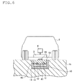
structure 1b according to the second embodiment of the present invention is the same as thepaved structure 1a according to the first embodiment except that anelectromagnetic wave shield 14 is concaved on the inner surface of thedepression 10 as shown inFig. 6 . The explanation of the same part is left out. - The
electromagnetic wave shield 14 cuts off the electromagnetic waves emitted from thepower feeding body 12 so as not to propagate electromagnetic waves in the ground. - The
electromagnetic wave shield 14 preferably contains aggregate formed of stainless, aluminum, or combination thereof and a concrete covering the aggregate. - Alternatively, the
electromagnetic wave shield 14 is preferably formed from a stainless panel or net, an aluminum panel or net, or combination thereof. - The method of constructing the
paved structure 1b according to the second embodiment is described below in reference toFigs. 7(a) to 7(e) . - First, in the step shown in
Fig 7(a) , adepression 10 with a desired width and a desired depth is formed in the pavedstructure 1b with a cutter, etc. - Subsequently, in the step shown in
Fig 7(b) , anelectromagnetic wave shield 14 is concaved in contact with the inner surface of thedepression 10. - Subsequently, in the step shown in
Fig 7(c) , amagnetic member 11 is laid in theelectromagnetic wave shield 14. - Subsequently, in the step shown in
Fig. 7(d) ,power feeding bodies 12 are laid on themagnetic member 11. Since integrally wired, thepower feeding bodies 12 are efficiently laid by a cable laying car and a cable reel car. - Subsequently, in the step shown in
Fig. 7(e) , a powerfeeding body protector 13 is laid to cover thepower feeding bodies 12 laid on themagnetic member 11. For example, cement asphalt emulsion mortar (CAM) can be used as the powerfeeding body protector 13. - In addition, dense-graded asphalt concrete or polymer-cement concrete may be laid on the surface layer of the paved
structure 1b. - In addition, a
visible part 60 may be provided on the surface layer of the pavedstructure 1b to make the position in which thepower feeding bodies 12 are buried visible from a travelingbody 2. Specifically, thevisible part 60 that is, for example, specially paved and extends in the direction in which the pavedstructure 1b extends is provided on thepaved structure 1b (road surface) in which thepower feeding bodies 12 are embedded to inform a driver who drives a travelingbody 2 about the position in which thepower feeding bodies 12 are buried. - The thus formed paved
structure 1b according to the second embodiment of the present invention can obtain a similar effect to that of the pavedstructure 1a according to the first embodiment. - In addition, the
paved structure 1b according to the second embodiment has anelectromagnetic wave shield 14 so as to cut off electromagnetic waves other than those emitted to a travelingbody 2. As a result, thepaved structure 1b can reduce electromagnetic waves propagating from thepower feeding bodies 12 to the ground. - Third embodiment The paved
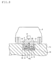
structure 1c according to the third embodiment of the present invention is the same as thepaved structure 1b according to the second embodiment except that theelectromagnetic wave shield 14 has apartition 14a in the center of the depression to form two grooves in the depression as shown inFig. 8 . The explanation of the same part is left out. - The
electromagnetic wave shield 14 has two grooves each having apower feeding body 12. - The
partition 14a of theelectromagnetic wave shield 14 separates thepower feeding bodies 12 laid in the respective grooves from each other so as to prevent electromagnetic waves emitted from the respectivepower feeding bodies 12 from canceling each other out. - The method of constructing the paved
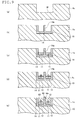
structure 1c according to the third embodiment is described below in reference toFigs. 9(a) to 9(e) . - First, in the step shown in
Fig 9(a) , adepression 10 with a desired width and a desired depth is formed in the pavedstructure 1b with a cutter, etc. - Subsequently, in the step shown in
Fig 9(b) , anelectromagnetic wave shield 14 with apartition 14a forming two grooves is laid in contact with the inner surface of thedepression 10. - Subsequently, in the step shown in
Fig 9(c) , amagnetic member 11 is laid in each of the two grooves of theelectromagnetic wave shield 14. - Subsequently, in the step shown in
Fig. 9(d) ,power feeding bodies 12 are laid on themagnetic member 11 laid in each of the grooves. Since integrally wired, thepower feeding bodies 12 are efficiently laid by a cable laying car and a cable reel car. - Subsequently, in the step shown in
Fig. 9(e) , a powerfeeding body protector 13 is laid to cover thepower feeding bodies 12 laid on themagnetic member 11. For example, cement asphalt emulsion mortar (CAM) can be used as the powerfeeding body protector 13. - In addition, dense-graded asphalt concrete or polymer-cement concrete may be laid on the surface layer of the paved
structure 1c. - In addition, a
visible part 60 may be provided on the surface layer of the pavedstructure 1c, particularly the surface of thepartition 14a of theelectromagnetic wave shield 14 to make the position in which thepower feeding bodies 12 are buried visible from a travelingbody 2. Specifically, thevisible part 60 that is, for example, specially paved and extends in the direction in which thepartition 14a extends is provided on the surface of thepartition 14a to inform a driver who drives a travelingbody 2 about the position in which thepower feeding bodies 12 are buried. - The thus formed paved
structure 1c according to the third embodiment of the present invention can obtain a similar effect to that of the pavedstructure 1b according to the second embodiment. - Furthermore, the paved
structure 1c according to the third embodiment has apartition 14a of theelectromagnetic wave shield 14 so as to prevent electromagnetic waves emitted from the respectivepower feeding bodies 12 from canceling each other out. As a result, the pavedstructure 1c can emit strong electromagnetic waves to a travelingbody 2. - Other embodiments The present invention is described above in reference to the embodiments. However, it should not be understood that the description and the drawings incorporated in this disclosure limit the present invention. Various alternative embodiments, examples, and operation technologies of this disclosure will be apparent to those skilled in the art.
- For example, the
visible part 60 is paved with a red color mixture by mixing iron oxide (red oxide, Fe2O3) in the dense-graded asphalt mixture for surface layer of thepaved structures visible part 60 has a different color from those of other pavements to inform a driver about the position in which thepower feeding bodies 12 are buried. Thevisible part 60 may be paved with a retro reflective material to inform a driver by its reflection about the position in which thepower feeding body 12 is buried. - It thus should be understood that the present invention encompasses various embodiments, etc. not described herein. Therefore, the present invention is limited only to matters to define an invention which are stated in claims appropriate from this disclosure.
-
- 1a, 1b, 1c Paved structure
- 2 Traveling body
- 3 Power receivers
- 4 Secondary cell
- 5 Power feeding facility
- 10 Depressions
- 11 Magnetic member
- 12 Power feeding body
- 13 Power feeding body protector
- 14 Electromagnetic wave shield
- 40 Reinforcement
- 50 Power feeding line
- 60 Visible part
Claims (12)
- A paved structure feeding power to a power receiver provided in a traveling body through an electromagnetic wave, comprising:a depression extending in the direction in which the traveling body runs;a magnetic member laid in the depression so that a flat upper surface is formed;a power feeding body laid on the upper surface of the magnetic member to feed power to the power receiver through an electromagnetic wave; anda power feeding body protector laid in the depression to cover the power feeding body.
- The paved structure according to claim 1, further comprising:a reinforcement with a predetermined width laid in the depression, whereinthe power feeding body is attached to the reinforcement.
- The paved structure according to claim 2, wherein
the reinforcement is a mesh net with a constant width and a constant length, and
the power feeding body is coiled and attached to the net. - The paved structure according to claim 1 or 2, wherein an electromagnetic wave shield is concaved on the inner surface of the depression, and the magnetic member is laid in the concave of the electromagnetic wave shield.
- The paved structure according to claim 4, wherein the electromagnetic wave shield has a partition in the center of the depression to form two grooves in the depression, and the power feeding body is laid in each of the two grooves.
- The paved structure according to claim 4 or 5, wherein the electromagnetic wave shield is formed from a stainless panel or net, an aluminum panel or net, or combination thereof.
- The paved structure according to any one of claims 1 to 6, wherein the power feeding body protector is the same magnetic body as or a different magnetic body from the magnetic member.
- The paved structure according to any one of claims 1 to 7, wherein the magnetic member contains magnetic slag.
- The paved structure according to any one of claims 1 to 8, further comprising:a visible part visible from the traveling body, whereinthe visible part is provided on the upper surface of the power feeding body protector over the power feeding body.
- The paved structure according to claim 9, wherein the visible part is colored in a color different from that of the power feeding body protector.
- The paved structure according to claim 9 or 10, wherein the visible part is formed of a retro reflective material.
- A method of constructing the paved structure according to any one of claims 1 to 11, comprising the steps of:forming a depression in the paved structure;laying a magnetic member in the depression; andlaying a power feeding body on the magnetic member.
Applications Claiming Priority (2)
| Application Number | Priority Date | Filing Date | Title |
|---|---|---|---|
| JP2013058497A JP5374657B1 (en) | 2013-03-21 | 2013-03-21 | Pavement structure and construction method of pavement structure |
| PCT/JP2013/073062 WO2014147860A1 (en) | 2013-03-21 | 2013-08-28 | Paved structure and construction method for paved structure |
Publications (2)
| Publication Number | Publication Date |
|---|---|
| EP3000934A1 true EP3000934A1 (en) | 2016-03-30 |
| EP3000934A4 EP3000934A4 (en) | 2016-11-02 |
Family
ID=49954970
Family Applications (1)
| Application Number | Title | Priority Date | Filing Date |
|---|---|---|---|
| EP13878844.3A Withdrawn EP3000934A4 (en) | 2013-03-21 | 2013-08-28 | COATING STRUCTURE AND METHOD FOR CONSTRUCTION THEREOF |
Country Status (6)
| Country | Link |
|---|---|
| US (1) | US9873333B2 (en) |
| EP (1) | EP3000934A4 (en) |
| JP (1) | JP5374657B1 (en) |
| KR (1) | KR101790422B1 (en) |
| CN (1) | CN105189869B (en) |
| WO (1) | WO2014147860A1 (en) |
Cited By (3)
| Publication number | Priority date | Publication date | Assignee | Title |
|---|---|---|---|---|
| IT201800006495A1 (en) * | 2018-06-20 | 2019-12-20 | Procedure for the direct installation on the road of inductors for inductive transfer of electrical power | |
| US11328852B2 (en) | 2018-05-17 | 2022-05-10 | Ihi Corporation | Coil device |
| EP4056413A1 (en) * | 2021-03-11 | 2022-09-14 | STILL GmbH | Battery charging device for inductive charging, in particular dynamic and / or stationary inductive charging, of a traction battery of a vehicle |
Families Citing this family (19)
| Publication number | Priority date | Publication date | Assignee | Title |
|---|---|---|---|---|
| JP6457767B2 (en) * | 2014-09-19 | 2019-01-23 | 大成建設株式会社 | Embedded structure of feeding conductor |
| US10059213B2 (en) | 2015-11-13 | 2018-08-28 | Nio Usa, Inc. | Charging devices within wheel portions |
| US10189363B2 (en) | 2015-11-13 | 2019-01-29 | Nio Usa, Inc. | Electric vehicle roadway charging system and method of use |
| US10093195B2 (en) | 2015-11-13 | 2018-10-09 | Nio Usa, Inc. | Integrated vehicle charging panel system and method of use |
| US10336194B2 (en) * | 2015-11-13 | 2019-07-02 | Nio Usa, Inc. | Electric vehicle charging device alignment and method of use |
| JP6647625B2 (en) * | 2016-03-11 | 2020-02-14 | 大成建設株式会社 | Embedded structure of power supply conductor and non-contact type power supply travel path |
| JP6606047B2 (en) | 2016-10-03 | 2019-11-13 | 株式会社東芝 | Power transmission equipment |
| JP6810932B2 (en) * | 2016-10-17 | 2021-01-13 | 大成建設株式会社 | Buried structure of power feeding electrode and non-contact type power feeding path |
| CN106592371A (en) * | 2016-12-16 | 2017-04-26 | 武汉理工大学 | Asphalt pavement capable of providing charging function for vehicles in driving process |
| CN110014896B (en) * | 2017-10-20 | 2022-02-08 | 鸿海精密工业股份有限公司 | Wireless charging automobile and wireless charging road |
| CN108944497A (en) * | 2018-05-30 | 2018-12-07 | 合肥市春华起重机械有限公司 | A kind of AGV trolley wireless charging system |
| CN116657536A (en) * | 2018-09-30 | 2023-08-29 | 王奎 | Urban Dust Cleaning System and Application and Urban Dust Cleaning Method |
| JP7331394B2 (en) * | 2019-03-15 | 2023-08-23 | 株式会社デンソー | Power supply system while driving |
| JP7684105B2 (en) * | 2020-06-24 | 2025-05-27 | 太平洋セメント株式会社 | Concrete pavement, precast body, their manufacturing method and non-contact type power supply runway |
| DE102020212391A1 (en) * | 2020-09-30 | 2022-03-31 | Mahle International Gmbh | Roadway ceiling panel for an inductive assembly |
| JP7845034B2 (en) * | 2022-05-10 | 2026-04-14 | 株式会社大林組 | Buried structure and burial method for power supply devices |
| JP7815981B2 (en) * | 2022-05-10 | 2026-02-18 | 株式会社大林組 | Buried structure and method for power supply device |
| JP2024123444A (en) * | 2023-03-01 | 2024-09-12 | 東亜道路工業株式会社 | Pavement structure and construction method for pavement structure |
| WO2025134895A1 (en) * | 2023-12-18 | 2025-06-26 | オムロン株式会社 | Power transmission device, power reception device, and system |
Family Cites Families (40)
| Publication number | Priority date | Publication date | Assignee | Title |
|---|---|---|---|---|
| US4361202A (en) * | 1979-06-15 | 1982-11-30 | Michael Minovitch | Automated road transportation system |
| JPH0789199B2 (en) | 1988-03-19 | 1995-09-27 | 富士写真フイルム株式会社 | Radiation field contour candidate point detection method |
| US5390118A (en) * | 1990-10-03 | 1995-02-14 | Aisin Seiki Kabushiki Kaisha | Automatic lateral guidance control system |
| CA2056521A1 (en) | 1990-11-29 | 1992-05-30 | Kiyoshi Takashashi | Method for constructing asphalted road having heating pipe laid thereunder |
| JPH0678406A (en) * | 1992-08-28 | 1994-03-18 | Daifuku Co Ltd | Noncontact power feeding equipment for moving body |
| JPH0767205A (en) * | 1993-08-25 | 1995-03-10 | Sumitomo Electric Ind Ltd | Primary coil and secondary coil in non-contact power supply device for mobile body |
| US5573090A (en) | 1994-05-05 | 1996-11-12 | H. R. Ross Industries, Inc. | Raodway-powered electric vehicle system having onboard power metering and communication channel features |
| US5595271A (en) | 1995-08-07 | 1997-01-21 | Tseng; Ling-Yuan | Electric vehicle pick-up position control |
| JPH11238638A (en) | 1998-02-23 | 1999-08-31 | Toyota Autom Loom Works Ltd | Non-contact type charging device |
| JP2000116036A (en) * | 1998-09-29 | 2000-04-21 | Yamaha Motor Co Ltd | Transportation equipment |
| CN1463868A (en) | 2002-06-14 | 2003-12-31 | 李善伯 | Method for collecting electric vehicle trough power transmission and running state information |
| JP2005224045A (en) * | 2004-02-06 | 2005-08-18 | Mitsubishi Heavy Ind Ltd | Non-contact power feeding device and wire-less system provided with it |
| JP2007012775A (en) * | 2005-06-29 | 2007-01-18 | Daido Steel Co Ltd | Electromagnetic wave absorber |
| KR100884188B1 (en) | 2005-07-01 | 2009-02-17 | 옥은호 | Underground electric rail road and electric vehicle with current collector |
| JP4209437B2 (en) * | 2006-11-10 | 2009-01-14 | 三菱重工業株式会社 | Non-contact power feeding device for mobile body and protection device therefor |
| JP2010022183A (en) * | 2008-02-08 | 2010-01-28 | Suri-Ai:Kk | Electric vehicle and inductive power-transmission device suitable therefor |
| DE102008013649B4 (en) | 2008-03-11 | 2010-04-15 | Sew-Eurodrive Gmbh & Co. Kg | Apparatus for contactless energy transmission and use of the device |
| JP5467569B2 (en) | 2009-01-21 | 2014-04-09 | 国立大学法人埼玉大学 | Non-contact power feeding device |
| KR100944113B1 (en) | 2009-02-27 | 2010-02-24 | 한국과학기술원 | Power supply system and method for electric vehicles |
| JP5354539B2 (en) | 2009-08-25 | 2013-11-27 | 国立大学法人埼玉大学 | Non-contact power feeding device |
| US8221024B2 (en) | 2009-09-03 | 2012-07-17 | General Atomics | Embedded module for linear synchronous motor |
| KR101104813B1 (en) | 2009-10-16 | 2012-01-17 | 한국과학기술원 | Electric vehicle feeder protected by concrete structure |
| US20130092491A1 (en) | 2009-10-16 | 2013-04-18 | Korea Advanced Institute Of Science And Technology | Power supply apparatus for on-line electric vehicle, method for forming same and magnetic field cancelation apparatus |
| US20110094840A1 (en) | 2009-10-26 | 2011-04-28 | Masami Sakita | Electric highway system |
| JP5641891B2 (en) * | 2009-11-13 | 2014-12-17 | パナソニック株式会社 | Charging and feeding system for vehicles |
| WO2011074091A1 (en) | 2009-12-17 | 2011-06-23 | トヨタ自動車株式会社 | Shield and vehicle whereupon same is mounted |
| GB2476318A (en) | 2009-12-21 | 2011-06-22 | Bombardier Transp Gmbh | Laying electrical conductors along a track for a vehicle |
| KR101038759B1 (en) | 2009-12-21 | 2011-06-03 | 한국과학기술원 | Collector device for electric vehicle with active cancellation of emf |
| KR20110074350A (en) * | 2009-12-24 | 2011-06-30 | 한국과학기술원 | Electromagnetic Field Shielding Device and Method of Online Dual Rail Power Feeding System |
| WO2011078403A2 (en) | 2009-12-24 | 2011-06-30 | Rusk Intellectual Reserve Ag | Electric vehicle and electric supply arrangement for the same |
| KR101232036B1 (en) | 2010-10-13 | 2013-02-12 | 한국과학기술원 | Non-contact power transmission device and self-induction power feeding device |
| CN102465482A (en) | 2010-11-20 | 2012-05-23 | 孙善骏 | Mobile Electromagnetic Charging Station Road |
| CN201915316U (en) * | 2010-11-20 | 2011-08-03 | 孙善骏 | Mobile electromagnetic charging station road |
| GB2485617A (en) | 2010-11-22 | 2012-05-23 | Bombardier Transp Gmbh | Conductor arrangement for inductively transferring electric energy to a vehicle |
| GB2485616A (en) | 2010-11-22 | 2012-05-23 | Bombardier Transp Gmbh | Route for transferring electric energy to vehicles |
| CN201966647U (en) * | 2011-01-29 | 2011-09-07 | 孙善骏 | Charger for movable electromagnetic charged electric automobile |
| JP5777139B2 (en) * | 2011-02-23 | 2015-09-09 | 株式会社豊田中央研究所 | Vehicle power supply apparatus and vehicle power supply method |
| WO2012141357A1 (en) | 2011-04-15 | 2012-10-18 | 한국과학기술원 | Power feeding rail module using non-contact magnetic inductive charging method, road structure using same, and method for constructing road |
| JP2012248747A (en) | 2011-05-30 | 2012-12-13 | Toyota Industries Corp | Shield device of resonance type non-contact power supply system |
| CN103828189A (en) * | 2011-07-26 | 2014-05-28 | Lg伊诺特有限公司 | Wireless power transmitter and wireless power receiver |
-
2013
- 2013-03-21 JP JP2013058497A patent/JP5374657B1/en active Active
- 2013-08-28 EP EP13878844.3A patent/EP3000934A4/en not_active Withdrawn
- 2013-08-28 WO PCT/JP2013/073062 patent/WO2014147860A1/en not_active Ceased
- 2013-08-28 CN CN201380074841.0A patent/CN105189869B/en not_active Expired - Fee Related
- 2013-08-28 US US14/778,285 patent/US9873333B2/en not_active Expired - Fee Related
- 2013-08-28 KR KR1020157025755A patent/KR101790422B1/en active Active
Cited By (5)
| Publication number | Priority date | Publication date | Assignee | Title |
|---|---|---|---|---|
| US11328852B2 (en) | 2018-05-17 | 2022-05-10 | Ihi Corporation | Coil device |
| GB2586737B (en) * | 2018-05-17 | 2022-05-25 | Ihi Corp | Coil device |
| IT201800006495A1 (en) * | 2018-06-20 | 2019-12-20 | Procedure for the direct installation on the road of inductors for inductive transfer of electrical power | |
| WO2019244070A1 (en) * | 2018-06-20 | 2019-12-26 | Politecnico Di Torino | Method for direct roadway installation of inductors for inductive electric power transfer |
| EP4056413A1 (en) * | 2021-03-11 | 2022-09-14 | STILL GmbH | Battery charging device for inductive charging, in particular dynamic and / or stationary inductive charging, of a traction battery of a vehicle |
Also Published As
| Publication number | Publication date |
|---|---|
| US9873333B2 (en) | 2018-01-23 |
| KR101790422B1 (en) | 2017-10-25 |
| CN105189869B (en) | 2018-05-18 |
| JP2014181546A (en) | 2014-09-29 |
| JP5374657B1 (en) | 2013-12-25 |
| KR20150135276A (en) | 2015-12-02 |
| WO2014147860A1 (en) | 2014-09-25 |
| CN105189869A (en) | 2015-12-23 |
| US20160229294A1 (en) | 2016-08-11 |
| EP3000934A4 (en) | 2016-11-02 |
Similar Documents
| Publication | Publication Date | Title |
|---|---|---|
| US9873333B2 (en) | Paved structure and construction method for paved structure | |
| US9855847B2 (en) | Trough, paved structure, and construction method for paved structure | |
| US10170230B2 (en) | Power supply apparatus | |
| CN104271384B (en) | vehicle | |
| JP6647625B2 (en) | Embedded structure of power supply conductor and non-contact type power supply travel path | |
| US9979229B2 (en) | Power supply apparatus | |
| US20110248574A1 (en) | Mobile type non-contact power feeding device | |
| CN102405580A (en) | Ultra-light thin power supply device and power acquisition device for electric vehicle | |
| KR20130040864A (en) | Wireless power antenna alignment adjustment system for vehicles | |
| US9902278B2 (en) | Power supplying device, wireless power-supplying system, and bag unit | |
| Mahmud et al. | Efficient wireless power charging of electric vehicle by modifying the magnetic characteristics of the transmitting medium | |
| CN104245402A (en) | Coil unit and electric vehicle | |
| CN105052012A (en) | Power supplying device, power receiving device, and power supplying system | |
| JP7557977B2 (en) | Embedded structure of coil for non-contact power supply | |
| JP6457767B2 (en) | Embedded structure of feeding conductor | |
| WO2013145579A1 (en) | Power supply apparatus | |
| US9748773B2 (en) | Contactless power supply device | |
| JP6810932B2 (en) | Buried structure of power feeding electrode and non-contact type power feeding path | |
| JP2022060100A (en) | Wireless power feeding floor structure | |
| KR102846743B1 (en) | A wireless power transmitter and a wireless power receiver, and a wireless power transmission system including the same | |
| JP2025136381A (en) | Underground power supply equipment | |
| WO2025027487A1 (en) | Arrangement for inductively supplying energy and method for manufacturing the same |
Legal Events
| Date | Code | Title | Description |
|---|---|---|---|
| PUAI | Public reference made under article 153(3) epc to a published international application that has entered the european phase |
Free format text: ORIGINAL CODE: 0009012 |
|
| 17P | Request for examination filed |
Effective date: 20150917 |
|
| AK | Designated contracting states |
Kind code of ref document: A1 Designated state(s): AL AT BE BG CH CY CZ DE DK EE ES FI FR GB GR HR HU IE IS IT LI LT LU LV MC MK MT NL NO PL PT RO RS SE SI SK SM TR |
|
| AX | Request for extension of the european patent |
Extension state: BA ME |
|
| DAX | Request for extension of the european patent (deleted) | ||
| A4 | Supplementary search report drawn up and despatched |
Effective date: 20161006 |
|
| RIC1 | Information provided on ipc code assigned before grant |
Ipc: E01C 7/08 20060101ALI20160929BHEP Ipc: B60M 7/00 20060101ALI20160929BHEP Ipc: H01F 38/14 20060101ALI20160929BHEP Ipc: B60L 11/18 20060101ALI20160929BHEP Ipc: E01C 9/00 20060101AFI20160929BHEP Ipc: H02J 7/02 20060101ALI20160929BHEP Ipc: B60L 5/00 20060101ALI20160929BHEP Ipc: E01C 1/00 20060101ALI20160929BHEP Ipc: H02J 50/10 20160101ALI20160929BHEP |
|
| 17Q | First examination report despatched |
Effective date: 20181015 |
|
| STAA | Information on the status of an ep patent application or granted ep patent |
Free format text: STATUS: THE APPLICATION HAS BEEN WITHDRAWN |
|
| 18W | Application withdrawn |
Effective date: 20181211 |