EP3000683B1 - System and method for control of an autonomous drive related operation - Google Patents
System and method for control of an autonomous drive related operation Download PDFInfo
- Publication number
- EP3000683B1 EP3000683B1 EP14186157.5A EP14186157A EP3000683B1 EP 3000683 B1 EP3000683 B1 EP 3000683B1 EP 14186157 A EP14186157 A EP 14186157A EP 3000683 B1 EP3000683 B1 EP 3000683B1
- Authority
- EP
- European Patent Office
- Prior art keywords
- vehicle
- occupant
- front seat
- determined
- controlling
- Prior art date
- Legal status (The legal status is an assumption and is not a legal conclusion. Google has not performed a legal analysis and makes no representation as to the accuracy of the status listed.)
- Active
Links
- 238000000034 method Methods 0.000 title claims description 31
- 238000004590 computer program Methods 0.000 claims description 9
- 238000002604 ultrasonography Methods 0.000 claims description 5
- 210000002683 foot Anatomy 0.000 description 105
- 238000001514 detection method Methods 0.000 description 18
- 230000008901 benefit Effects 0.000 description 9
- 230000004913 activation Effects 0.000 description 6
- 230000006870 function Effects 0.000 description 6
- 230000006378 damage Effects 0.000 description 4
- 208000027418 Wounds and injury Diseases 0.000 description 3
- 208000014674 injury Diseases 0.000 description 3
- 238000012986 modification Methods 0.000 description 3
- 230000004048 modification Effects 0.000 description 3
- 230000000295 complement effect Effects 0.000 description 2
- 230000007812 deficiency Effects 0.000 description 2
- 230000007613 environmental effect Effects 0.000 description 2
- 238000012544 monitoring process Methods 0.000 description 2
- 230000008569 process Effects 0.000 description 2
- 239000007787 solid Substances 0.000 description 2
- 206010033670 Panic reaction Diseases 0.000 description 1
- 230000003213 activating effect Effects 0.000 description 1
- 230000008859 change Effects 0.000 description 1
- 238000010276 construction Methods 0.000 description 1
- 238000010586 diagram Methods 0.000 description 1
- 230000000694 effects Effects 0.000 description 1
- 238000004519 manufacturing process Methods 0.000 description 1
- 238000012806 monitoring device Methods 0.000 description 1
- 230000001953 sensory effect Effects 0.000 description 1
- 210000003371 toe Anatomy 0.000 description 1
- 230000001960 triggered effect Effects 0.000 description 1
Images


Classifications
-
- B—PERFORMING OPERATIONS; TRANSPORTING
- B60—VEHICLES IN GENERAL
- B60W—CONJOINT CONTROL OF VEHICLE SUB-UNITS OF DIFFERENT TYPE OR DIFFERENT FUNCTION; CONTROL SYSTEMS SPECIALLY ADAPTED FOR HYBRID VEHICLES; ROAD VEHICLE DRIVE CONTROL SYSTEMS FOR PURPOSES NOT RELATED TO THE CONTROL OF A PARTICULAR SUB-UNIT
- B60W30/00—Purposes of road vehicle drive control systems not related to the control of a particular sub-unit, e.g. of systems using conjoint control of vehicle sub-units, or advanced driver assistance systems for ensuring comfort, stability and safety or drive control systems for propelling or retarding the vehicle
-
- B—PERFORMING OPERATIONS; TRANSPORTING
- B60—VEHICLES IN GENERAL
- B60W—CONJOINT CONTROL OF VEHICLE SUB-UNITS OF DIFFERENT TYPE OR DIFFERENT FUNCTION; CONTROL SYSTEMS SPECIALLY ADAPTED FOR HYBRID VEHICLES; ROAD VEHICLE DRIVE CONTROL SYSTEMS FOR PURPOSES NOT RELATED TO THE CONTROL OF A PARTICULAR SUB-UNIT
- B60W50/00—Details of control systems for road vehicle drive control not related to the control of a particular sub-unit, e.g. process diagnostic or vehicle driver interfaces
- B60W50/08—Interaction between the driver and the control system
- B60W50/10—Interpretation of driver requests or demands
-
- B—PERFORMING OPERATIONS; TRANSPORTING
- B60—VEHICLES IN GENERAL
- B60K—ARRANGEMENT OR MOUNTING OF PROPULSION UNITS OR OF TRANSMISSIONS IN VEHICLES; ARRANGEMENT OR MOUNTING OF PLURAL DIVERSE PRIME-MOVERS IN VEHICLES; AUXILIARY DRIVES FOR VEHICLES; INSTRUMENTATION OR DASHBOARDS FOR VEHICLES; ARRANGEMENTS IN CONNECTION WITH COOLING, AIR INTAKE, GAS EXHAUST OR FUEL SUPPLY OF PROPULSION UNITS IN VEHICLES
- B60K35/00—Arrangement of adaptations of instruments
-
- B60K35/10—
-
- B—PERFORMING OPERATIONS; TRANSPORTING
- B60—VEHICLES IN GENERAL
- B60N—SEATS SPECIALLY ADAPTED FOR VEHICLES; VEHICLE PASSENGER ACCOMMODATION NOT OTHERWISE PROVIDED FOR
- B60N2/00—Seats specially adapted for vehicles; Arrangement or mounting of seats in vehicles
- B60N2/002—Seats provided with an occupancy detection means mounted therein or thereon
-
- B—PERFORMING OPERATIONS; TRANSPORTING
- B60—VEHICLES IN GENERAL
- B60N—SEATS SPECIALLY ADAPTED FOR VEHICLES; VEHICLE PASSENGER ACCOMMODATION NOT OTHERWISE PROVIDED FOR
- B60N2/00—Seats specially adapted for vehicles; Arrangement or mounting of seats in vehicles
- B60N2/02—Seats specially adapted for vehicles; Arrangement or mounting of seats in vehicles the seat or part thereof being movable, e.g. adjustable
- B60N2/0224—Non-manual adjustments, e.g. with electrical operation
- B60N2/0244—Non-manual adjustments, e.g. with electrical operation with logic circuits
-
- B—PERFORMING OPERATIONS; TRANSPORTING
- B60—VEHICLES IN GENERAL
- B60N—SEATS SPECIALLY ADAPTED FOR VEHICLES; VEHICLE PASSENGER ACCOMMODATION NOT OTHERWISE PROVIDED FOR
- B60N2/00—Seats specially adapted for vehicles; Arrangement or mounting of seats in vehicles
- B60N2/02—Seats specially adapted for vehicles; Arrangement or mounting of seats in vehicles the seat or part thereof being movable, e.g. adjustable
- B60N2/04—Seats specially adapted for vehicles; Arrangement or mounting of seats in vehicles the seat or part thereof being movable, e.g. adjustable the whole seat being movable
- B60N2/06—Seats specially adapted for vehicles; Arrangement or mounting of seats in vehicles the seat or part thereof being movable, e.g. adjustable the whole seat being movable slidable
-
- B—PERFORMING OPERATIONS; TRANSPORTING
- B60—VEHICLES IN GENERAL
- B60W—CONJOINT CONTROL OF VEHICLE SUB-UNITS OF DIFFERENT TYPE OR DIFFERENT FUNCTION; CONTROL SYSTEMS SPECIALLY ADAPTED FOR HYBRID VEHICLES; ROAD VEHICLE DRIVE CONTROL SYSTEMS FOR PURPOSES NOT RELATED TO THE CONTROL OF A PARTICULAR SUB-UNIT
- B60W50/00—Details of control systems for road vehicle drive control not related to the control of a particular sub-unit, e.g. process diagnostic or vehicle driver interfaces
- B60W50/0098—Details of control systems ensuring comfort, safety or stability not otherwise provided for
-
- G—PHYSICS
- G06—COMPUTING; CALCULATING OR COUNTING
- G06F—ELECTRIC DIGITAL DATA PROCESSING
- G06F3/00—Input arrangements for transferring data to be processed into a form capable of being handled by the computer; Output arrangements for transferring data from processing unit to output unit, e.g. interface arrangements
- G06F3/01—Input arrangements or combined input and output arrangements for interaction between user and computer
- G06F3/017—Gesture based interaction, e.g. based on a set of recognized hand gestures
-
- B60K2360/146—
-
- B60K2360/21—
-
- B—PERFORMING OPERATIONS; TRANSPORTING
- B60—VEHICLES IN GENERAL
- B60W—CONJOINT CONTROL OF VEHICLE SUB-UNITS OF DIFFERENT TYPE OR DIFFERENT FUNCTION; CONTROL SYSTEMS SPECIALLY ADAPTED FOR HYBRID VEHICLES; ROAD VEHICLE DRIVE CONTROL SYSTEMS FOR PURPOSES NOT RELATED TO THE CONTROL OF A PARTICULAR SUB-UNIT
- B60W50/00—Details of control systems for road vehicle drive control not related to the control of a particular sub-unit, e.g. process diagnostic or vehicle driver interfaces
- B60W2050/0062—Adapting control system settings
- B60W2050/0075—Automatic parameter input, automatic initialising or calibrating means
- B60W2050/0095—Automatic control mode change
-
- B—PERFORMING OPERATIONS; TRANSPORTING
- B60—VEHICLES IN GENERAL
- B60W—CONJOINT CONTROL OF VEHICLE SUB-UNITS OF DIFFERENT TYPE OR DIFFERENT FUNCTION; CONTROL SYSTEMS SPECIALLY ADAPTED FOR HYBRID VEHICLES; ROAD VEHICLE DRIVE CONTROL SYSTEMS FOR PURPOSES NOT RELATED TO THE CONTROL OF A PARTICULAR SUB-UNIT
- B60W2540/00—Input parameters relating to occupants
Definitions
- the present invention is direted to a method, a computer program, and a control system for controlling an autonomous drive related operation of a vehicle.
- Vehicles equipped with control systems for autonomous drive are capable of travelling and interacting with other road-users without direct manual control by one or more occupants in the vehicle. These control systems may be engaged or disengaged depending on whether the occupant in the driving seat wishes to manually control, in example, to drive, the vehicle or if an autonomous driving mode is preferred.
- Autonomous driving in general, comprises a plurality of different operations, where each operation is associated with one or more states.
- the state of an autonomous drive related operation of the vehicle is determined in a controlled manner, and in line with the intent and wishes of one or more occupants of the vehicle, thus ensuring a safe operation of the vehicle when in an autonomous driving mode. For instance, engaging or disengaging an autonomous driving mode of the vehicle should not be performed in an un-safe or otherwise unexpected manner, since this would jeopardize the safety of the one or more vehicle occupants, as well as of other road-users in the vicinity of the vehicle.
- the vehicle occupants should have the freedom to engage in tasks not related to driving in order to provide as positive a travelling experience as possible.
- provision should not come at the expense of reduced safety. Consequently, any actions by the vehicle should not be performed in an un-safe manner, nor should it be executed when the occupant does not expect it or wish for it.
- An object of the present invention is to provide a control system and a method for controlling an autonomous drive related operation of a vehicle which seek to mitigate, alleviate, or eliminate one or more of the above-identified deficiencies.
- This object is obtained by a method in a vehicle for controlling an autonomous drive related operation of the vehicle, according to claim 1. Consequently, since control of the autonomous drive related operation of the vehicle is performed based on a detected pre-determined foot arrangement of a vehicle occupant, the control may be performed in line with the expectations of the occupant, thus providing for a more secure control, as well as for increased freedom of movement for arms and feet for a more positive travelling experience for the occupant.
- the autonomous drive related operation is a configuration of an interior of the vehicle.
- one configuration of an interior of the vehicle is change in position of a front seat of the vehicle.
- the configuration of the interior comprises retracting the front seat in a direction towards a back end of the vehicle such that the driver's foot is out of reach of the one or more pedals of the vehicle, or when returning the front seat in a direction towards a front end of the vehicle such that the front seat is returned to the driving position.
- the retracting of the front seat leads to increased room for arms and feet to perform non-driving tasks, and the returning of the front seat to the initial position allows the occupant to, for example, assume control of the vehicle.
- a computer program comprising computer program code which, when executed in a vehicle, causes the vehicle to execute a method according to any of the methods disclosed herein.
- Example advantages of the computer program correspond to the example advantages already described in relation to the method.
- EP 2 314 489 discloses a method involving determining current vehicle guidance state.
- a driver state value is analyzed by sensors to automatically detect a derivative value with a respective reference value in order to prepare the driver for a warning.
- DE 42 26 747 discloses an autopilot used to maintain vehicle spacing from a preceding vehicle, by controlling engine load and/or vehicle brakes.
- a driving seat is pivoted into a second position when the autopilot is brought into operation and is automatically returned to a driving position in the event of a driving situation which cannot be handled by the autopilot.
- US 2013/245894 discloses a driver assistance system for a motor vehicle encompassing at least one foot sensor for monitoring a foot of a driver, a control unit for deciding on a safety measure based on a detection result of the foot sensor, and an environmental sensor to detect an approach toward an outside obstacle, and is set up to only implement the safety measure if a detection result of the environmental sensor indicates a danger that contact will be made with the obstacle.
- DE 10 2011 121484 discloses a method for assisting a driver in operating a vehicle comprising a plurality of assistance systems, wherein data relating to a vehicle state, vehicle surroundings, and a driver of the vehicle are captured continuously by means of a sensor device.
- US 2010/222976 discloses a driver assistance system including a control device, which has a self-deactivation function, and a monitoring device which is designed for monitoring presence of a driver in a driver's seat and for triggering the self-deactivation function in the absence of the driver.
- US 2004/122575 discloses a device provided for detecting a seating position of a passenger in a motor vehicle, the device being characterized in that it outputs at least one instruction to the passenger for adjusting the seat as a function of a signal from a sensory system.
- DE 10 2013 000632 discloses a vehicle having a seat arrangement in an internal space.
- a vehicle seat of a seat row of the seat arrangement is arranged such that the vehicle seat is brought in a lying position, in which a backrest is inclined rearwards relative to a seat part, and into another lying position, in which the backrest is inclined rearwards relative to the seat part, and the vehicle seat is moved in the area of another row of seats.
- the lying positions are initiated manually or automatically depending on the mode of the vehicle by a vehicle passenger.
- DE 101 44 878 discloses a passenger identification system comprising sensors identifying passengers in a vehicle.
- the system has for a vehicle seat a foot sensor, a seat sensor and a back rest sensor.
- a control unit links the sensor signals.
- the sensors each have at least one panel of sensor elements.
- the back rest sensor has at least two sensor panels.
- At least one sensor produces signals as a function of the pressure applied.
- At least one sensor is a passive sensor.
- DE 10 2013 224118 discloses a method for controlling a vehicle which includes obtaining, via at least one detecting device, behavior information of a driver in the vehicle, and transitioning control statuses of the vehicle according to the driver behavior information.
- control system in a vehicle for controlling an autonomous drive related operation of the vehicle, according to claim 6.
- Example advantages of the control system correspond to the example advantages already described in relation to the method.
- control unit is configured to control a configuration of an interior of the vehicle.
- At least one sensor of the control system comprises any one of a camera, an infra-red, IR, detector, an ultra-sound detector, and a pressure sensor.
- the at least one sensor is integrated into a floor and/or a pedal of the vehicle, and/or mounted on a front side of the front seat, under a dashboard, in connection to a ceiling, and/or in connection to a vertical surface adjacent to the ceiling of the vehicle and/or an interior surface of the vehicle in which a foot arrangement of the occupant is within a field of view of the at least one sensor. Consequently, the at least one sensor may be mounted in a wide variety of locations throughout the vehicle. This leads to advantages when it comes to production of the vehicle, and also to robustness of the control system since the system may rely on sensing from more than one location in the vehicle.
- Example advantages of this vehicle correspond to the example advantages already described in relation to the method and the control system.
- Example embodiments presented herein are directed towards a system and method of controlling an autonomous drive related operation of a vehicle based on a detection of a predetermined foot arrangement.
- an autonomous drive related operation may be provided upon detecting a particular foot arrangement of an occupant of the vehicle. Examples of such an autonomous drive related operation are the entering and exiting of an autonomous driving mode or an internal configuration of the vehicle in the form of seat retraction.
- the autonomous drive related operation control presented herein provides an occupant of the vehicle an opportunity to operate the vehicle in a safe manner with increased freedom of movement for arms and feet that are no longer engaged in controlling the vehicle.
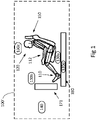
- Figure 1 shows an overview of a general vehicle 100' according to the invention presented herein.
- the present technique is discussed and illustrated below in connection to a vehicle 100 resembling a car, it is noted that the present invention is applicable also to other types of vehicles. Consequently, the types of vehicles 100' encompassed by the present invention comprise cars, trucks, busses and construction equipment, as well as air-planes, boats, ships, and space craft.
- the vehicle 100' shown in Figure 1 has at least one occupant 120 in a front seat 150 of the vehicle 100'. It should be appreciated that the term occupant shall be a driver of the vehicle and/or a passenger in the vehicle 100.
- the occupant 120 has feet 110 and at least one arm 112.
- the vehicle 100' is arranged for autonomous drive related operations.
- the vehicle 100 is equipped with one or more sensors 130a-d connected to a control unit 140 of the vehicle.
- a control system of the vehicle 100' then comprises at least the sensors 130a-d and the control unit 140.
- the sensors 130a-d may be configured to measure a position or input provided by the occupant 120.
- the vehicle 100' further comprises a vehicle control device 171 configured for manual control the vehicle 100'.
- vehicle control device 171 is one or more pedals of the vehicle. These one or more pedals are, according to aspects, used to control vehicle velocity by, for example, throttle, brake, or by vehicle clutch.
- a primary control which, when activated, engages autonomous drive of the vehicle 100'.
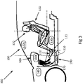
- FIG. 2 illustrates an example vehicle 100 in form of a car.
- An occupant 120 in the vehicle is arranged in a normal operating position 200.
- This position is suitable, in example, when having assumed manual control of the vehicle by means of the vehicle control device 171, for example, by one or more pedals 170, and/or a steering wheel of the vehicle, not shown in Figure 2 .
- This normal operating position 200 is configured to facilitate efficient control of the vehicle by the occupant in a safe manner, but is not necessarily configured for maximum comfort of the occupant.
- the vehicle 100 shown in Figure 2 comprises one or more sensors 130a-d.
- one or more sensors 130a may be mounted on a front side of the front seat 150 of the vehicle 100.
- the type of the sensor mounted in connection to the front seat may comprise an infra-red, IR, detector, an ultra-sound detector, and/or a camera.
- the sensors 130a may be mounted on any location or position within the front seat 150 such that the sensors 103a are capable of detecting the feet 110 or arm 112 of the occupant 120.
- one or more sensors 130b are further mounted under a dashboard 160 of the vehicle 100, which sensors may also comprise IR detectors, ultra-sound detectors, and/or cameras. It should be appreciated that the sensors 130b may be mounted on any other location of the dashboard, for example, embedded in any location of the dashboard such that the sensors 130b are capable of detecting the feet 110 or arm 112 of the occupant 120.
- one or more sensors 130c are mounted in connection to a ceiling 190, and/or in connection to a vertical surface adjacent to the ceiling 190 of the vehicle 100.
- the one or more sensors may also be mounted on any an interior surface of the vehicle in which a foot arrangement of the occupant is within a field of view of the one or more sensor.
- These one or more sensors may comprise IR detectors, ultra-sound detectors, and/or cameras.
- the one or more sensors 130d are further integrated into a floor 180 and/or into a pedal 170 of the vehicle 100.
- Figure 3 illustrates detection of a predetermined foot arrangement of the occupant 120.
- the occupant 120 when wishing to control an autonomous drive related operation of the vehicle, such as, for example, engaging an autonomous driving mode of the vehicle 100 or altering a configuration of an interior of the vehicle, arranges his feet in accordance with a pre-determined foot arrangement 111.
- FIG. 3 illustrates an arrangement in which the feet 110 have been moved 310 from the one or more pedals 170 to a position aft of the pedals.
- This pre-determined foot arrangement 111 is detected by the control unit 140 using sensor signals supplied to the control unit 140 by one or more of the above-mentioned sensors 130a-d.
- an autonomous drive related operation of the vehicle 100 is controlled by detecting a pre-determined foot arrangement 111 of an occupant 120 in a front seat 150 of the vehicle, and controlling a state of the autonomous drive related operation, based on the detected predetermined foot arrangement 111.
- the actual detecting of the pre-determined foot arrangement is achieved by sensing of the feet 110 of the occupant 120, by means of one or more of the above-mentioned sensors 130a-d.
- the actual definition of the pre-determined foot-arrangement differs between different aspects of the present invention, as will now be exemplified.
- a pre-determined foot arrangement is defined as a foot arrangement in which the feet 110 are located beyond a certain minimum distance from the one or more pedals 170.
- This type of pre-determined foot arrangement is detected by sensing a distance between the feet 110 of the occupant 120 and the one or more pedals 170 of the vehicle 100, 100', followed by comparison of the sensed distance to a pre-determined distance threshold.
- Another example involves defining a pre-determined zone, i.e., a three-dimensional volume, in the vehicle 100, 100'. If the feet 110 of the occupant 120 are located within this pre-determined zone, then the feet are located according to the pre-determined foot arrangement. This type of pre-determined foot arrangement is detected by means of sensing if both feet 110 of the occupant 120 are located in the pre-determined zone in the vehicle 100, 100'.
- Yet another example relates to how the occupant moves the feet 110 over a pre-determined time duration.
- a pre-determined foot arrangement is thus detected by sensing a motion of the feet 110 of the occupant 120 over the pre-determined time duration, and comparing this sensed motion to a pre-determined motion pattern.
- An example of this type of pre-determined foot arrangement will be discussed in connection to Figure 7 below, where a panic reaction of the occupant 120 is described.
- One example of said autonomous drive related operation of the vehicle is engaging or disengaging autonomous drive of the vehicle.
- autonomous drive When autonomous drive is engaged, the vehicle assumes control, while, during periods of disengaged autonomous drive, the occupant 120 of the vehicle assumes manual control of the vehicle.
- autonomous drive of the vehicle 100, 100' is engaged or disengaged by a primary control unit, such as an electrical switch or voice command system.
- a primary control unit such as an electrical switch or voice command system.
- This primary control unit may of course be activated by mistake but the manual controls system continues to function so occupant retains the ability to control the vehicle.
- detection of the predetermined foot arrangement in a position near the pedals may be used as a secondary complementary control unit for disengaging autonomous drive of the vehicle.
- autonomous drive of the vehicle is arranged to be disengaged by first activating a primary control unit, followed by arranging feet 110 of an occupant 120 according to a pre-determined foot arrangement where the feet of the occupant are at the proper position on the floor, for example, position 111 in Figures 7b and 7c , for the driver to return to manual driving position.
- detecting the pre-determined foot arrangement constitutes one of at least two conditions for the controlling of the autonomous drive related operation of the vehicle 100, 100'.
- an occupant of the vehicle 100, 100' activates said primary control, but fails to arrange feet 110 according to the pre-determined foot arrangement
- the vehicle will issue an alert signal when detection of the pre-determined foot arrangement does not occur within a pre-determined time duration measured from a time instant when at least one other condition, such as the activation of the primary control, out of the at least two conditions is fulfilled.
- the occupant is thus notified of the reason why the manual drive operation fails to commence.
- the detection of the pre-determined foot arrangement may also serve as a primary activation while the engagement of a control unit may serve as a secondary activation.
- the autonomous drive related operation of the vehicle comprises a configuration of an interior of the vehicle.
- the interior of the vehicle is configured according to the state of the autonomous drive related operation of the vehicle.
- This configuration comprises displacing the front seat 150 of the vehicle 100 in order to provide for a more positive travelling experience, for example, by allowing an occupant to engage in activities that would normally not be possible during a manual driving mode.
- FIG. 4 A configuration of the vehicle interior in which the front seat 150 has been retracted in order to, e.g., provide for more legroom of the occupant 150 is shown in Figure 4 .
- the heels of the feet 110 are located on the floor 180 of the vehicle where they were placed prior to retraction of the front seat 150. In this position the toes of the feet 110 are not in a position to contact the one or more pedals 170, shown in Figure 4 by an arc extending from the feet 110.
- the configuration of the vehicle interior in which the front seat 150 has been retracted leads to increased safety in that the occupant cannot inadvertently active controls of the vehicle, such as the one or more pedals, e.g., by moving the front seat rearward to the retracted position.
- the comfort and safety of the vehicle occupant is increased, providing for a more positive and safe travelling experience.
- seat retraction is only executed following a detection of the pre-determined foot arrangement 111, thus, seat retraction is not executed in a manner unexpected by the occupant 120 of the front seat 150 of the vehicle 100, 100'. Controlling the configuration of the vehicle interior is thus, by the present invention, executed in a secure fashion, without causing injury or danger to the occupant 120 of the vehicle.
- the configuring of vehicle interior requires prior engagement of an autonomous driving mode of the vehicle 100, 100'.
- a driver seat of the vehicle 100 is only retracted when autonomous drive is engaged.
- a passenger seat can, however, be retracted more freely, i.e., regardless of whether autonomous drive is engaged or not.
- Figures 5a and 5b illustrate some example un-wanted scenarios which are avoided by application of the present technique of controlling a configuration of an interior of the vehicle.
- Figure 5a illustrates an example scenario in which the vehicle interior has been reconfigured by retraction 320 of the front seat 150, without first ensuring that the feet 110 of the occupant 120 are free of the one or more pedals 170. Thus, the feet 110 have become stuck 210 under or in connection to the one or more pedals 170, causing injury or at least discomfort for the occupant 120.
- Figure 5b illustrates an example scenario in which the vehicle interior has been reconfigured by retraction of the front seat 150, without first ensuring that the heels of the feet 110 of the occupant 120 have been retracted.
- the heels may be dragged 330 on the floor 180 of the vehicle 100.
- the advantage of the example embodiments presented herein is to ensure that the feet are in a proper position during the retraction of the seat, as such, the dragging of the occupant's heels may be avoided.
- the front seat 150 should be returned to the initial position. For example, this may happen because the vehicle is about to leave a certified autonomous driving road or zone. Another example is that a crash or another hazard situation requiring the driver to take control is about to occur. A passenger in the vehicle 100 may also, for such reasons, want the passenger side front seat to be returned to the initial position.
- FIGS. 6a and 6b illustrate two example pre-determined foot arrangements which are not preferred.
- Figure 6a illustrates an example scenario with a pre-determined foot arrangement 111b in which the feet 110 of the occupant are located within a zone 230 such as to potentially contact and push the one or more pedals 170 upon returning the front seat 150 to the initial position, as shown in Figure 2 .
- Figure 6b illustrates another example scenario with a pre-determined foot arrangement 111c in which the feet 110 of the occupant 120 are positioned within a zone 240 right in front of the front seat 150.
- the feet 110 would be pushed over the floor 180 of the vehicle, or stuck under the front seat 150.
- detecting an undesired foot arrangement 111b, 111c of an occupant 120 in a front seat 150 of the vehicle 100, 100' results in a deferral of a vehicle interior configuration. Since, had a vehicle interior configuration been executed, harm or discomfort would have been inflicted on the occupant 120. According to some aspects, a warning or indication for the occupant 120 to correct the current foot arrangement may be given following a deferral of a vehicle interior configuration.
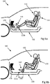
- Figures 7a-7c illustrate an example sequence of events which, according to the present teaching, results in a configuration of the vehicle interior such that the front seat 150 is returned to the initial position, and furthermore also results in a disengagement of autonomous drive of the vehicle 100.
- the occupant 120 notices a danger, or is otherwise prompted to resume manual control of the vehicle 100.
- the occupant 120 therefore reaches for one or more control devices of the vehicle 100, such as, e.g., a steering wheel, not shown in Figures 7a-7c , or the one or more pedals 170 of the vehicle.
- One example of this reaching is a panic gesture by the occupant 120.
- an arm 112 of the occupant is outstretched, and the torso of the occupant is moved in a forward direction, i.e., towards the one or more control devices of the vehicle. This reaching is illustrated in Figure 7a .
- the feet 110 are lifted off the floor of the vehicle 100. Following the reaction shown in Figure 7a , the feet 110 of the occupant are then, as illustrated in Figure 7b , returned to the floor of the vehicle within a pre-determined area or zone, avoiding contact with the one or more pedals, whereupon a pre-determined feet arrangement 111 is detected and the front seat 150 is returned to the initial position, as illustrated in Figure 2 .
- the vehicle 100, 100' is configured to detect an attempted engagement of the occupant 120 with a control device of the vehicle 100, 100', such as a steering wheel or the one or more pedals 170.
- the vehicle is furthermore configured to return the front seat 150 in a direction towards a front end of the vehicle when both feet 110 of the occupant 120 are located in a pre-determined zone in the vehicle 100, 100'.
- an occupant of the vehicle 100, 100' activates said primary control, but fails to arrange feet 110 according to the pre-determined foot arrangement
- the vehicle will issue an alert signal when detection of the pre-determined foot arrangement does not occur within a pre-determined time duration measured from a time instant when at least one other condition, such as the activation of the primary control, out of the at least two conditions is fulfilled.
- the occupant is thus notified of the reason why the autonomous drive related operation fails to commence.
- the detection of the predetermined foot arrangement may also serve as a primary activation while the engagement of a control unit may serve as a secondary activation.
- Figure 8 is a flow diagram depicting example method steps, performed in a vehicle 100, 100' substantially as described herein, for controlling an autonomous drive related operation of the vehicle 100, 100'. It should be appreciated that Figure 8 comprises some operations which are illustrated with solid border, and some operations which are illustrated with a dashed border.
- the operations which are comprised in a solid border are operations which are comprised in the broadest aspect of the present invention.
- the operations which are comprised in a dashed border are example embodiments which may be comprised in, or a part of, or are further operations which may be taken in addition to the operations of the broader example aspects. It should furthermore be appreciated that the operations need not be performed in order.
- the vehicle 100, 100' is configured to issue 8 an alert signal when a detection of a predetermined foot arrangement does not occur within a pre-determined time duration measured from a time instant when at least one other condition out of the at least two conditions is fulfilled.
- the control unit 140 discussed above, e.g., in relation to Figure 1 is configured to issue the alert signal when the detecting does not occur within a pre-determined time duration measured from the time instant when at least one other condition out of the at least two conditions is fulfilled.
- the vehicle 100, 100' is configured to detect 10 a pre-determined foot arrangement 111 of an occupant 120 in a front seat 150 of the vehicle 100, 100'.
- the control unit 140 is configured to detect the pre-determined foot arrangement 111 based on input signals from the one or more sensors 130a-130d comprised in the vehicle 100. Operation 10 is discussed above in connection to at least Figure 2 and under subheading 'Vehicle overview'. Some examples of different predetermined foot arrangements have been discussed in connection to Figures 3 , 6a , 6b , and 7a-7c above.
- the detection of the pre-determined foot arrangement of the occupant 120 enables controlling an autonomous drive related operation of the vehicle in line with expectations of the occupant, thus providing for a more secure control, as well as for increased comfort leading to a more positive travelling experience for the occupant.
- the vehicle 100, 100' is configured to sense 12 a distance between the feet 110 of the occupant 120 and one or more pedals 170 of the vehicle 100, 100', and compare the distance to a pre-determined distance threshold.
- One or more out of the one or more sensors 130a-d comprised in the vehicle 100 and discussed above in connection to at least Figure 2 , and under subheading 'Vehicle overview', is arranged to sense the distance between the feet 110 of the occupant 120 and one or more pedals 170 of the vehicle 100, 100'.
- the control unit 140 is then configured to compare the distance to the pre-determined distance threshold.
- Having access to information about the distance between the feet and the one or more pedals 170 may be used by the vehicle to secure that the feet cannot get stuck under the pedals of the vehicle upon retracting the front seat, as discussed in connection to Figure 5a above. Having access to information about the distance between the feet and the one or more pedals 170 is also helpful in order to determine if the front seat 150 can be safely returned to the initial position as discussed in connection to Figures 6a and 6b .
- the vehicle 100, 100' is configured to sense 14 if both feet 110 of the occupant 120 are located in a pre-determined zone in the vehicle 100, 100'.
- the sensing of the distance one or more out of the one or more sensors 130a-d comprised in the vehicle 100 and discussed above in connection to at least Figure 3 , and under subheading 'Detecting a pre-determined foot arrangement', is arranged to sense if both feet 110 of the occupant 120 are located in a pre-determined zone in the vehicle 100, 100', and to communicate this sensed data to the control unit 140.
- Information related to the location of the feet in a pre-determined zone in the vehicle 100, 100' is one way of securing that the front seat can be retracted without causing discomfort or injury to the occupant, as discussed in connection to at least Figures 5a and 5b above.
- Knowledge of whether both feet 110 of the occupant 120 are located in the pre-determined zone in the vehicle 100, 100' is also useful in securing that the front seat 150 can be returned to initial position without, e.g., the feet getting stuck under the front seat or accidentally contacting the one or more pedals 170 of the vehicle 100, as was discussed above in connection to Figures 6a and 6b .
- the vehicle 100, 100' is configured to sense 16 a motion of the feet 110 of the occupant 120 over a pre-determined time duration, and to compare the motion to a pre-determined motion pattern during said time duration.
- one or more out of the one or more sensors 130a-d comprised in the vehicle 100 and discussed above in connection to at least Figure 3 , and under subheading 'Detecting a pre-determined foot arrangement' is arranged to sense the motion of the feet 110 of the occupant 120 over the pre-determined time duration, and to communicate this sensed data to the control unit 140.
- the control unit 140 is then arranged to compare the motion to a pre-determined motion pattern during said time duration.
- the vehicle 100, 100' is configured to detect 17 an attempted engagement of the occupant 120 with a control device of the vehicle 100, 100', in which case the vehicle is further configured to return 20 the front seat 150 in a direction towards a front end of the vehicle 100, 100' when both feet 110 of the occupant 120 are located in a predetermined zone in the vehicle 100, 100'.
- the one or more sensors 130a-130d are configured to detect this attempted engagement of the occupant 120 with a control device of the vehicle 100, 100'.
- the control unit 140 is configured to receive sensor data from the one or more sensors 130a-130d related to the attempted engagement, and to return the front seat 150 in a direction towards a front end of the vehicle 100, 100' when both feet 110 of the occupant 120 are located in a pre-determined zone in the vehicle 100, 100'.
- the vehicle is further configured to control 18 a state of the autonomous drive related operation, based on the detected pre-determined foot arrangement 111.
- the control unit 140 is configured to perform the controlling, based on sensor data received from the one or more sensors 130a-d comprised in the vehicle 100, 100'. The controlling was discussed above under at least the subheading 'Controlling vehicle autonomous driving mode'.
- control of the autonomous drive related operation of the vehicle is performed based on a detected pre-determined foot arrangement of a vehicle occupant, the control may be performed in line with the expectations of the occupant, thus providing for a more secure control, as well as for increased comfort and a more positive travelling experience for the occupant.
- detection of the pre-determined foot arrangement 111 may constitute one of at least two conditions for the controlling 18 discussed above.
- detection of the pre-determined foot arrangement may be used as a secondary complementary control unit for, e.g., disengaging autonomous drive of the vehicle or seat retraction. This is helpful in order to provide an additional degree of control of, e.g., an autonomous drive mode of the vehicle 100.
- the vehicle 100, 100' is further arranged to configure 19 an interior of the vehicle 100, 100' as part of controlling 18 the state of the autonomous drive related operation.
- the configuring of the interior is performed by the control unit 140 based on sensor data received from the one or more sensors 130a-d.
- the configuring of vehicle interior was discussed above under at least subheading 'Configuration of vehicle interior'.
- the vehicle 100, 100' is further configured to retract 20 the front seat 150 in a direction towards a back end of the vehicle 100, 100' such that the occupant 120 is out of reach of the one or more pedals 170 of the vehicle 100, 100'.
- the control unit 140 is configured to retract the front seat, which retracting of the front seat was discussed above under at least the subheading 'Configuration of vehicle interior'.
- the retracting of the front seat leads to increased room for occupant feet and arms, and the returning of the front seat to the initial position allows the occupant to, for example, assume control of the vehicle.
- increased comfort is provided without jeopardizing occupant safety.
- the vehicle 100, 100' is further arranged to return 21 the front seat 150 in a direction towards a front end of the vehicle 100, 100' when both feet 110 of the occupant 120 are located in a pre-determined zone in the vehicle 100, 100', as part of controlling 18 the state of the autonomous drive related operation.
- the front seat 150 is returned a direction towards a front end of the vehicle 100, 100' such that the front seat is in an initial position.
- the control unit 140 is configured to return the front seat. The returning of the front seat is further discussed above under at least the subheading 'Configuration of vehicle interior'.
- the vehicle 100, 100' is configured to engage or disengage an autonomous driving mode of the vehicle 100, 100'.
- the vehicle 100' is arranged for autonomous drive related operations.
- a computer-readable medium may include removable and non-removable storage devices including, but not limited to, Read Only Memory (ROM), Random Access Memory (RAM), compact discs (CDs), digital versatile discs (DVD), etc.
- program modules may include routines, programs, objects, components, data structures, etc. that perform particular tasks or implement particular abstract data types.
- Computer-executable instructions, associated data structures, and program modules represent examples of program code for executing steps of the methods disclosed herein. The particular sequence of such executable instructions or associated data structures represents examples of corresponding acts for implementing the functions described in such steps or processes.
Description
- The present invention is direted to a method, a computer program, and a control system for controlling an autonomous drive related operation of a vehicle.
- Vehicles equipped with control systems for autonomous drive are capable of travelling and interacting with other road-users without direct manual control by one or more occupants in the vehicle. These control systems may be engaged or disengaged depending on whether the occupant in the driving seat wishes to manually control, in example, to drive, the vehicle or if an autonomous driving mode is preferred. Autonomous driving, in general, comprises a plurality of different operations, where each operation is associated with one or more states.
- It is of great importance that the state of an autonomous drive related operation of the vehicle is determined in a controlled manner, and in line with the intent and wishes of one or more occupants of the vehicle, thus ensuring a safe operation of the vehicle when in an autonomous driving mode. For instance, engaging or disengaging an autonomous driving mode of the vehicle should not be performed in an un-safe or otherwise unexpected manner, since this would jeopardize the safety of the one or more vehicle occupants, as well as of other road-users in the vicinity of the vehicle.
- Furthermore, the vehicle occupants should have the freedom to engage in tasks not related to driving in order to provide as positive a travelling experience as possible. However, that provision should not come at the expense of reduced safety. Consequently, any actions by the vehicle should not be performed in an un-safe manner, nor should it be executed when the occupant does not expect it or wish for it.
- It is an object of the present disclosure to provide solutions to, or at least mitigate, the above mentioned deficiencies in the art.
- An object of the present invention is to provide a control system and a method for controlling an autonomous drive related operation of a vehicle which seek to mitigate, alleviate, or eliminate one or more of the above-identified deficiencies.
- This object is obtained by a method in a vehicle for controlling an autonomous drive related operation of the vehicle, according to claim 1. Consequently, since control of the autonomous drive related operation of the vehicle is performed based on a detected pre-determined foot arrangement of a vehicle occupant, the control may be performed in line with the expectations of the occupant, thus providing for a more secure control, as well as for increased freedom of movement for arms and feet for a more positive travelling experience for the occupant.
- According to claim 1, the autonomous drive related operation is a configuration of an interior of the vehicle. According to the invention, one configuration of an interior of the vehicle is change in position of a front seat of the vehicle. Thus, controlling an autonomous drive related operation of the vehicle, i.e. configuring an interior of the vehicle to avoid inadvertent control manipulations during autonomous driving, is performed in a safe manner in-line with the expectations of the vehicle occupant.
- According to claim 1, the configuration of the interior comprises retracting the front seat in a direction towards a back end of the vehicle such that the driver's foot is out of reach of the one or more pedals of the vehicle, or when returning the front seat in a direction towards a front end of the vehicle such that the front seat is returned to the driving position. The retracting of the front seat leads to increased room for arms and feet to perform non-driving tasks, and the returning of the front seat to the initial position allows the occupant to, for example, assume control of the vehicle.
- There is also disclosed herein a computer program comprising computer program code which, when executed in a vehicle, causes the vehicle to execute a method according to any of the methods disclosed herein. Example advantages of the computer program correspond to the example advantages already described in relation to the method.
-
EP 2 314 489 discloses a method involving determining current vehicle guidance state. A driver state value is analyzed by sensors to automatically detect a derivative value with a respective reference value in order to prepare the driver for a warning. -
DE 42 26 747 discloses an autopilot used to maintain vehicle spacing from a preceding vehicle, by controlling engine load and/or vehicle brakes. A driving seat is pivoted into a second position when the autopilot is brought into operation and is automatically returned to a driving position in the event of a driving situation which cannot be handled by the autopilot. -
US 2013/245894 discloses a driver assistance system for a motor vehicle encompassing at least one foot sensor for monitoring a foot of a driver, a control unit for deciding on a safety measure based on a detection result of the foot sensor, and an environmental sensor to detect an approach toward an outside obstacle, and is set up to only implement the safety measure if a detection result of the environmental sensor indicates a danger that contact will be made with the obstacle. -
DE 10 2011 121484 discloses a method for assisting a driver in operating a vehicle comprising a plurality of assistance systems, wherein data relating to a vehicle state, vehicle surroundings, and a driver of the vehicle are captured continuously by means of a sensor device. -
US 2010/222976 discloses a driver assistance system including a control device, which has a self-deactivation function, and a monitoring device which is designed for monitoring presence of a driver in a driver's seat and for triggering the self-deactivation function in the absence of the driver. -
US 2004/122575 discloses a device provided for detecting a seating position of a passenger in a motor vehicle, the device being characterized in that it outputs at least one instruction to the passenger for adjusting the seat as a function of a signal from a sensory system. -
DE 10 2013 000632 discloses a vehicle having a seat arrangement in an internal space. A vehicle seat of a seat row of the seat arrangement is arranged such that the vehicle seat is brought in a lying position, in which a backrest is inclined rearwards relative to a seat part, and into another lying position, in which the backrest is inclined rearwards relative to the seat part, and the vehicle seat is moved in the area of another row of seats. The lying positions are initiated manually or automatically depending on the mode of the vehicle by a vehicle passenger. -
DE 101 44 878 discloses a passenger identification system comprising sensors identifying passengers in a vehicle. The system has for a vehicle seat a foot sensor, a seat sensor and a back rest sensor. A control unit links the sensor signals. The sensors each have at least one panel of sensor elements. The back rest sensor has at least two sensor panels. At least one sensor produces signals as a function of the pressure applied. At least one sensor is a passive sensor.DE 10 2013 224118 discloses a method for controlling a vehicle which includes obtaining, via at least one detecting device, behavior information of a driver in the vehicle, and transitioning control statuses of the vehicle according to the driver behavior information. - The object is also obtained by a control system in a vehicle for controlling an autonomous drive related operation of the vehicle, according to claim 6. Example advantages of the control system correspond to the example advantages already described in relation to the method.
- According to claim 6, the control unit is configured to control a configuration of an interior of the vehicle. Thus, by controlling the configuration of an interior of the vehicle, increased comfort for the occupant is enabled without jeopardizing the safety of the occupant.
- According to claim 7, at least one sensor of the control system comprises any one of a camera, an infra-red, IR, detector, an ultra-sound detector, and a pressure sensor. Thus, a plurality of options is provided for detecting the pre-determined foot arrangement of an occupant in a front seat of the vehicle. This leads to ease of implementation, and robustness due to the possibility to incorporate more than one type of sensor in the detecting of the pre-determined foot arrangement.
- According to some further embodiments, the at least one sensor is integrated into a floor and/or a pedal of the vehicle, and/or mounted on a front side of the front seat, under a dashboard, in connection to a ceiling, and/or in connection to a vertical surface adjacent to the ceiling of the vehicle and/or an interior surface of the vehicle in which a foot arrangement of the occupant is within a field of view of the at least one sensor. Consequently, the at least one sensor may be mounted in a wide variety of locations throughout the vehicle. This leads to advantages when it comes to production of the vehicle, and also to robustness of the control system since the system may rely on sensing from more than one location in the vehicle.
- In addition to the control system, there is furthermore disclosed herein a vehicle comprising the control system according to the present technique. Example advantages of this vehicle correspond to the example advantages already described in relation to the method and the control system.
- Further objects, features, and advantages of the present invention will appear from the following detailed description, wherein some aspects of the invention will be described in more detail with reference to the accompanying drawings, in which:
-
Figure 1 shows an overview of a vehicle, according to some of the aspects presented herein; -
Figure 2 shows a vehicle with an occupant arranged in a normal operating position; -
Figure 3 illustrates detection of a predetermined foot arrangement of an occupant, according to some of the aspects presented herein; -
Figure 4 shows a vehicle in which a front seat of the vehicle has been retracted rearward, according to some of the aspects presented herein; -
Figures 5a and 5b illustrate potential problems in retracting a front seat of a vehicle, according to some of the aspects presented herein; -
Figures 6a and 6b illustrate potential problems in returning a front seat of a vehicle to an initial position; -
Figures 7a-7c illustrate a panic gesture by an occupant in a vehicle, according to some of the aspects presented herein; and -
Figure 8 is a flowchart illustrating embodiments of example operations which may be performed in a vehicle, according to some of the aspects presented herein. - Aspects of the present invention will be described more fully hereinafter with reference to the accompanying drawings. The apparatus, computer program and methods disclosed herein can, however, be realized in many different forms and should not be construed as being limited to the aspects set forth herein. Like numbers in the drawings refer to like elements throughout.
- Example embodiments presented herein are directed towards a system and method of controlling an autonomous drive related operation of a vehicle based on a detection of a predetermined foot arrangement. According to the invention, upon detecting a particular foot arrangement of an occupant of the vehicle, an autonomous drive related operation may be provided. Examples of such an autonomous drive related operation are the entering and exiting of an autonomous driving mode or an internal configuration of the vehicle in the form of seat retraction. The autonomous drive related operation control presented herein provides an occupant of the vehicle an opportunity to operate the vehicle in a safe manner with increased freedom of movement for arms and feet that are no longer engaged in controlling the vehicle.
- The remainder of the text is organized as follows. First, an overview of a vehicle and the components of a vehicle according to the example embodiment presented herein are provided under the subheading 'Vehicle overview'. Thereafter, aspects regarding the detection for the control of the autonomous drive related operation are provided under the subheading 'Detecting a pre-determined foot arrangement'. Examples of controlling an autonomous drive related operation based on the detection are provided under the subheading 'Controlling vehicle autonomous driving mode state' and 'Configuration of vehicle interior'. Finally, example operations which may be taken by a vehicle according to the example embodiments presented herein are provided under the subheading 'Example vehicle operations'.
-
Figure 1 shows an overview of a general vehicle 100' according to the invention presented herein. Although the present technique is discussed and illustrated below in connection to avehicle 100 resembling a car, it is noted that the present invention is applicable also to other types of vehicles. Consequently, the types of vehicles 100' encompassed by the present invention comprise cars, trucks, busses and construction equipment, as well as air-planes, boats, ships, and space craft. - The vehicle 100' shown in
Figure 1 has at least oneoccupant 120 in afront seat 150 of the vehicle 100'. It should be appreciated that the term occupant shall be a driver of the vehicle and/or a passenger in thevehicle 100. Theoccupant 120 hasfeet 110 and at least onearm 112. - The vehicle 100' is arranged for autonomous drive related operations. In order to support controlling one or more states of the autonomous drive related operations, the
vehicle 100 is equipped with one ormore sensors 130a-d connected to acontrol unit 140 of the vehicle. A control system of the vehicle 100' then comprises at least thesensors 130a-d and thecontrol unit 140. Thesensors 130a-d may be configured to measure a position or input provided by theoccupant 120. - The vehicle 100' further comprises a
vehicle control device 171 configured for manual control the vehicle 100'. One example of such avehicle control device 171 is one or more pedals of the vehicle. These one or more pedals are, according to aspects, used to control vehicle velocity by, for example, throttle, brake, or by vehicle clutch. Another example of such avehicle control device 171 is a primary control which, when activated, engages autonomous drive of the vehicle 100'. -
Figure 2 illustrates anexample vehicle 100 in form of a car. Anoccupant 120 in the vehicle is arranged in anormal operating position 200. This position is suitable, in example, when having assumed manual control of the vehicle by means of thevehicle control device 171, for example, by one ormore pedals 170, and/or a steering wheel of the vehicle, not shown inFigure 2 . Thisnormal operating position 200 is configured to facilitate efficient control of the vehicle by the occupant in a safe manner, but is not necessarily configured for maximum comfort of the occupant. - The
vehicle 100 shown inFigure 2 comprises one ormore sensors 130a-d. In particular, one ormore sensors 130a may be mounted on a front side of thefront seat 150 of thevehicle 100. The type of the sensor mounted in connection to the front seat may comprise an infra-red, IR, detector, an ultra-sound detector, and/or a camera. It should be appreciated that thesensors 130a may be mounted on any location or position within thefront seat 150 such that the sensors 103a are capable of detecting thefeet 110 orarm 112 of theoccupant 120. - According to some aspects, one or
more sensors 130b are further mounted under adashboard 160 of thevehicle 100, which sensors may also comprise IR detectors, ultra-sound detectors, and/or cameras. It should be appreciated that thesensors 130b may be mounted on any other location of the dashboard, for example, embedded in any location of the dashboard such that thesensors 130b are capable of detecting thefeet 110 orarm 112 of theoccupant 120. - According to further aspects, one or
more sensors 130c are mounted in connection to aceiling 190, and/or in connection to a vertical surface adjacent to theceiling 190 of thevehicle 100. The one or more sensors may also be mounted on any an interior surface of the vehicle in which a foot arrangement of the occupant is within a field of view of the one or more sensor. These one or more sensors may comprise IR detectors, ultra-sound detectors, and/or cameras. - According to some aspects, the one or
more sensors 130d are further integrated into afloor 180 and/or into apedal 170 of thevehicle 100. Thus, there may be one ormore pressure sensors 130d integrated in, e.g., a floor carpet of thevehicle 100. -
Figure 3 illustrates detection of a predetermined foot arrangement of theoccupant 120. According to some aspects, theoccupant 120, when wishing to control an autonomous drive related operation of the vehicle, such as, for example, engaging an autonomous driving mode of thevehicle 100 or altering a configuration of an interior of the vehicle, arranges his feet in accordance with apre-determined foot arrangement 111. - The example of
Figure 3 illustrates an arrangement in which thefeet 110 have been moved 310 from the one ormore pedals 170 to a position aft of the pedals. Thispre-determined foot arrangement 111 is detected by thecontrol unit 140 using sensor signals supplied to thecontrol unit 140 by one or more of the above-mentionedsensors 130a-d. - In this way, an autonomous drive related operation of the
vehicle 100 is controlled by detecting apre-determined foot arrangement 111 of anoccupant 120 in afront seat 150 of the vehicle, and controlling a state of the autonomous drive related operation, based on the detectedpredetermined foot arrangement 111. - Thus, the actual detecting of the pre-determined foot arrangement is achieved by sensing of the
feet 110 of theoccupant 120, by means of one or more of the above-mentionedsensors 130a-d. The actual definition of the pre-determined foot-arrangement, however, differs between different aspects of the present invention, as will now be exemplified. - For instance, in one example, a pre-determined foot arrangement is defined as a foot arrangement in which the
feet 110 are located beyond a certain minimum distance from the one ormore pedals 170. This type of pre-determined foot arrangement is detected by sensing a distance between thefeet 110 of theoccupant 120 and the one ormore pedals 170 of thevehicle 100, 100', followed by comparison of the sensed distance to a pre-determined distance threshold. - Another example involves defining a pre-determined zone, i.e., a three-dimensional volume, in the
vehicle 100, 100'. If thefeet 110 of theoccupant 120 are located within this pre-determined zone, then the feet are located according to the pre-determined foot arrangement. This type of pre-determined foot arrangement is detected by means of sensing if bothfeet 110 of theoccupant 120 are located in the pre-determined zone in thevehicle 100, 100'. - Yet another example relates to how the occupant moves the
feet 110 over a pre-determined time duration. A pre-determined foot arrangement is thus detected by sensing a motion of thefeet 110 of theoccupant 120 over the pre-determined time duration, and comparing this sensed motion to a pre-determined motion pattern. An example of this type of pre-determined foot arrangement will be discussed in connection toFigure 7 below, where a panic reaction of theoccupant 120 is described. - One example of said autonomous drive related operation of the vehicle is engaging or disengaging autonomous drive of the vehicle. When autonomous drive is engaged, the vehicle assumes control, while, during periods of disengaged autonomous drive, the
occupant 120 of the vehicle assumes manual control of the vehicle. - According to some aspects, autonomous drive of the
vehicle 100, 100' is engaged or disengaged by a primary control unit, such as an electrical switch or voice command system. This primary control unit may of course be activated by mistake but the manual controls system continues to function so occupant retains the ability to control the vehicle. In order to disengage an autonomous driving mode and provide an additional level of control, detection of the predetermined foot arrangement in a position near the pedals may be used as a secondary complementary control unit for disengaging autonomous drive of the vehicle. Thus, according to an example operation of thevehicle 100, 100', autonomous drive of the vehicle is arranged to be disengaged by first activating a primary control unit, followed by arrangingfeet 110 of anoccupant 120 according to a pre-determined foot arrangement where the feet of the occupant are at the proper position on the floor, for example,position 111 inFigures 7b and 7c , for the driver to return to manual driving position. - In this way, autonomous drive of the
vehicle 100, 100' may be disengaged on condition that both the primary and secondary control units are activated. Thus, detecting the pre-determined foot arrangement, according to some aspects, constitutes one of at least two conditions for the controlling of the autonomous drive related operation of thevehicle 100, 100'. - According to further aspects, if an occupant of the
vehicle 100, 100' activates said primary control, but fails to arrangefeet 110 according to the pre-determined foot arrangement, then the vehicle will issue an alert signal when detection of the pre-determined foot arrangement does not occur within a pre-determined time duration measured from a time instant when at least one other condition, such as the activation of the primary control, out of the at least two conditions is fulfilled. The occupant is thus notified of the reason why the manual drive operation fails to commence. It should be appreciated that the detection of the pre-determined foot arrangement may also serve as a primary activation while the engagement of a control unit may serve as a secondary activation. - According to the invention the autonomous drive related operation of the vehicle comprises a configuration of an interior of the vehicle. Thus, the interior of the vehicle is configured according to the state of the autonomous drive related operation of the vehicle. This configuration comprises displacing the
front seat 150 of thevehicle 100 in order to provide for a more positive travelling experience, for example, by allowing an occupant to engage in activities that would normally not be possible during a manual driving mode. - A configuration of the vehicle interior in which the
front seat 150 has been retracted in order to, e.g., provide for more legroom of theoccupant 150 is shown inFigure 4 . Here, the heels of thefeet 110 are located on thefloor 180 of the vehicle where they were placed prior to retraction of thefront seat 150. In this position the toes of thefeet 110 are not in a position to contact the one ormore pedals 170, shown inFigure 4 by an arc extending from thefeet 110. - Additionally, the configuration of the vehicle interior in which the
front seat 150 has been retracted leads to increased safety in that the occupant cannot inadvertently active controls of the vehicle, such as the one or more pedals, e.g., by moving the front seat rearward to the retracted position. Thus, the comfort and safety of the vehicle occupant is increased, providing for a more positive and safe travelling experience. However, seat retraction is only executed following a detection of thepre-determined foot arrangement 111, thus, seat retraction is not executed in a manner unexpected by theoccupant 120 of thefront seat 150 of thevehicle 100, 100'. Controlling the configuration of the vehicle interior is thus, by the present invention, executed in a secure fashion, without causing injury or danger to theoccupant 120 of the vehicle. - In some vehicle operation scenarios it makes little sense to retract the front seat of an
occupant 120 driving thevehicle 100 when autonomous drive is not engaged. Accordingly, in some scenarios, the configuring of vehicle interior requires prior engagement of an autonomous driving mode of thevehicle 100, 100'. Thus, a driver seat of thevehicle 100 is only retracted when autonomous drive is engaged. A passenger seat can, however, be retracted more freely, i.e., regardless of whether autonomous drive is engaged or not. -
Figures 5a and 5b illustrate some example un-wanted scenarios which are avoided by application of the present technique of controlling a configuration of an interior of the vehicle.Figure 5a illustrates an example scenario in which the vehicle interior has been reconfigured byretraction 320 of thefront seat 150, without first ensuring that thefeet 110 of theoccupant 120 are free of the one ormore pedals 170. Thus, thefeet 110 have become stuck 210 under or in connection to the one ormore pedals 170, causing injury or at least discomfort for theoccupant 120. -
Figure 5b illustrates an example scenario in which the vehicle interior has been reconfigured by retraction of thefront seat 150, without first ensuring that the heels of thefeet 110 of theoccupant 120 have been retracted. Thus, when thefront seat 150 is retracted the heels may be dragged 330 on thefloor 180 of thevehicle 100. The advantage of the example embodiments presented herein is to ensure that the feet are in a proper position during the retraction of the seat, as such, the dragging of the occupant's heels may be avoided. - If the
occupant 120 wishes to resume manual control of thevehicle 100, or if an end to the autonomous driving mode of the vehicle is expected, then thefront seat 150 should be returned to the initial position. For example, this may happen because the vehicle is about to leave a certified autonomous driving road or zone. Another example is that a crash or another hazard situation requiring the driver to take control is about to occur. A passenger in thevehicle 100 may also, for such reasons, want the passenger side front seat to be returned to the initial position. - When there is reason to return the
front seat 150 to the initial position, i.e., to a position where the occupant may assume thenormal operating position 200, certain pre-determined foot-arrangements are preferred for theoccupant 120 when thefront seat 150 is returned to the forward position.Figures 6a and 6b illustrate two example pre-determined foot arrangements which are not preferred. -
Figure 6a illustrates an example scenario with apre-determined foot arrangement 111b in which thefeet 110 of the occupant are located within azone 230 such as to potentially contact and push the one ormore pedals 170 upon returning thefront seat 150 to the initial position, as shown inFigure 2 .Figure 6b illustrates another example scenario with apre-determined foot arrangement 111c in which thefeet 110 of theoccupant 120 are positioned within azone 240 right in front of thefront seat 150. Thus, should thefront seat 150 be returned under the circumstances illustrated in either ofFigure 6a or 6b , thefeet 110 would be pushed over thefloor 180 of the vehicle, or stuck under thefront seat 150. - Thus, detecting an
undesired foot arrangement occupant 120 in afront seat 150 of thevehicle 100, 100', according to some aspects, results in a deferral of a vehicle interior configuration. Since, had a vehicle interior configuration been executed, harm or discomfort would have been inflicted on theoccupant 120. According to some aspects, a warning or indication for theoccupant 120 to correct the current foot arrangement may be given following a deferral of a vehicle interior configuration. -
Figures 7a-7c illustrate an example sequence of events which, according to the present teaching, results in a configuration of the vehicle interior such that thefront seat 150 is returned to the initial position, and furthermore also results in a disengagement of autonomous drive of thevehicle 100. - In the sequence of events illustrated in
Figures 7a-7c , theoccupant 120 notices a danger, or is otherwise prompted to resume manual control of thevehicle 100. Theoccupant 120 therefore reaches for one or more control devices of thevehicle 100, such as, e.g., a steering wheel, not shown inFigures 7a-7c , or the one ormore pedals 170 of the vehicle. One example of this reaching is a panic gesture by theoccupant 120. During reaching for the one or more control devices of the vehicle, anarm 112 of the occupant is outstretched, and the torso of the occupant is moved in a forward direction, i.e., towards the one or more control devices of the vehicle. This reaching is illustrated inFigure 7a . Furthermore, according to some aspects, thefeet 110 are lifted off the floor of thevehicle 100. Following the reaction shown inFigure 7a , thefeet 110 of the occupant are then, as illustrated inFigure 7b , returned to the floor of the vehicle within a pre-determined area or zone, avoiding contact with the one or more pedals, whereupon apre-determined feet arrangement 111 is detected and thefront seat 150 is returned to the initial position, as illustrated inFigure 2 . - Thus, according to embodiments of the present invention, the
vehicle 100, 100' is configured to detect an attempted engagement of theoccupant 120 with a control device of thevehicle 100, 100', such as a steering wheel or the one ormore pedals 170. The vehicle is furthermore configured to return thefront seat 150 in a direction towards a front end of the vehicle when bothfeet 110 of theoccupant 120 are located in a pre-determined zone in thevehicle 100, 100'. - According to further aspects, if an occupant of the
vehicle 100, 100' activates said primary control, but fails to arrangefeet 110 according to the pre-determined foot arrangement, then the vehicle will issue an alert signal when detection of the pre-determined foot arrangement does not occur within a pre-determined time duration measured from a time instant when at least one other condition, such as the activation of the primary control, out of the at least two conditions is fulfilled. The occupant is thus notified of the reason why the autonomous drive related operation fails to commence. It should be appreciated that the detection of the predetermined foot arrangement may also serve as a primary activation while the engagement of a control unit may serve as a secondary activation. -
Figure 8 is a flow diagram depicting example method steps, performed in avehicle 100, 100' substantially as described herein, for controlling an autonomous drive related operation of thevehicle 100, 100'. It should be appreciated thatFigure 8 comprises some operations which are illustrated with solid border, and some operations which are illustrated with a dashed border. The operations which are comprised in a solid border are operations which are comprised in the broadest aspect of the present invention. The operations which are comprised in a dashed border are example embodiments which may be comprised in, or a part of, or are further operations which may be taken in addition to the operations of the broader example aspects. It should furthermore be appreciated that the operations need not be performed in order. - According to the invention, the
vehicle 100, 100' is configured to issue 8 an alert signal when a detection of a predetermined foot arrangement does not occur within a pre-determined time duration measured from a time instant when at least one other condition out of the at least two conditions is fulfilled. Thecontrol unit 140 discussed above, e.g., in relation toFigure 1 , is configured to issue the alert signal when the detecting does not occur within a pre-determined time duration measured from the time instant when at least one other condition out of the at least two conditions is fulfilled. - As explained above in relation to at least
Figure 2 , and under subheading 'Controlling vehicle autonomous driving mode state', the issuing of such an alert is helpful in order to notify the occupant of the reason an autonomous drive related operation fails to commence. - The
vehicle 100, 100' is configured to detect 10 apre-determined foot arrangement 111 of anoccupant 120 in afront seat 150 of thevehicle 100, 100'. Thecontrol unit 140 is configured to detect thepre-determined foot arrangement 111 based on input signals from the one ormore sensors 130a-130d comprised in thevehicle 100.Operation 10 is discussed above in connection to at leastFigure 2 and under subheading 'Vehicle overview'. Some examples of different predetermined foot arrangements have been discussed in connection toFigures 3 ,6a ,6b , and7a-7c above. - As noted above, the detection of the pre-determined foot arrangement of the
occupant 120 enables controlling an autonomous drive related operation of the vehicle in line with expectations of the occupant, thus providing for a more secure control, as well as for increased comfort leading to a more positive travelling experience for the occupant. - According to some aspects, the
vehicle 100, 100' is configured to sense 12 a distance between thefeet 110 of theoccupant 120 and one ormore pedals 170 of thevehicle 100, 100', and compare the distance to a pre-determined distance threshold. One or more out of the one ormore sensors 130a-d comprised in thevehicle 100 and discussed above in connection to at leastFigure 2 , and under subheading 'Vehicle overview', is arranged to sense the distance between thefeet 110 of theoccupant 120 and one ormore pedals 170 of thevehicle 100, 100'. Thecontrol unit 140 is then configured to compare the distance to the pre-determined distance threshold. Having access to information about the distance between the feet and the one ormore pedals 170 may be used by the vehicle to secure that the feet cannot get stuck under the pedals of the vehicle upon retracting the front seat, as discussed in connection toFigure 5a above. Having access to information about the distance between the feet and the one ormore pedals 170 is also helpful in order to determine if thefront seat 150 can be safely returned to the initial position as discussed in connection toFigures 6a and 6b . - According to some further aspects, the
vehicle 100, 100' is configured to sense 14 if bothfeet 110 of theoccupant 120 are located in a pre-determined zone in thevehicle 100, 100'. As for the sensing of the distance, one or more out of the one ormore sensors 130a-d comprised in thevehicle 100 and discussed above in connection to at leastFigure 3 , and under subheading 'Detecting a pre-determined foot arrangement', is arranged to sense if bothfeet 110 of theoccupant 120 are located in a pre-determined zone in thevehicle 100, 100', and to communicate this sensed data to thecontrol unit 140. - Information related to the location of the feet in a pre-determined zone in the
vehicle 100, 100' is one way of securing that the front seat can be retracted without causing discomfort or injury to the occupant, as discussed in connection to at leastFigures 5a and 5b above. Knowledge of whether bothfeet 110 of theoccupant 120 are located in the pre-determined zone in thevehicle 100, 100' is also useful in securing that thefront seat 150 can be returned to initial position without, e.g., the feet getting stuck under the front seat or accidentally contacting the one ormore pedals 170 of thevehicle 100, as was discussed above in connection toFigures 6a and 6b . - According to some other aspects, the
vehicle 100, 100' is configured to sense 16 a motion of thefeet 110 of theoccupant 120 over a pre-determined time duration, and to compare the motion to a pre-determined motion pattern during said time duration. Again, one or more out of the one ormore sensors 130a-d comprised in thevehicle 100 and discussed above in connection to at leastFigure 3 , and under subheading 'Detecting a pre-determined foot arrangement', is arranged to sense the motion of thefeet 110 of theoccupant 120 over the pre-determined time duration, and to communicate this sensed data to thecontrol unit 140. Thecontrol unit 140 is then arranged to compare the motion to a pre-determined motion pattern during said time duration. - One example of this motion of the feet was discussed above in connection to
Figure 7 , where a panic gesture of the occupant was detected, which detection triggered a returning of thefront seat 150 to initial position. - According to some further aspects, the
vehicle 100, 100' is configured to detect 17 an attempted engagement of theoccupant 120 with a control device of thevehicle 100, 100', in which case the vehicle is further configured to return 20 thefront seat 150 in a direction towards a front end of thevehicle 100, 100' when bothfeet 110 of theoccupant 120 are located in a predetermined zone in thevehicle 100, 100'. The one ormore sensors 130a-130d are configured to detect this attempted engagement of theoccupant 120 with a control device of thevehicle 100, 100'. Thecontrol unit 140 is configured to receive sensor data from the one ormore sensors 130a-130d related to the attempted engagement, and to return thefront seat 150 in a direction towards a front end of thevehicle 100, 100' when bothfeet 110 of theoccupant 120 are located in a pre-determined zone in thevehicle 100, 100'. - The attempted engagement of the occupant was exemplified in connection to
Figures 7a-7c above, where a panic gesture of theoccupant 120 was discussed. - The vehicle is further configured to control 18 a state of the autonomous drive related operation, based on the detected
pre-determined foot arrangement 111. Thecontrol unit 140 is configured to perform the controlling, based on sensor data received from the one ormore sensors 130a-d comprised in thevehicle 100, 100'. The controlling was discussed above under at least the subheading 'Controlling vehicle autonomous driving mode'. - Since control of the autonomous drive related operation of the vehicle is performed based on a detected pre-determined foot arrangement of a vehicle occupant, the control may be performed in line with the expectations of the occupant, thus providing for a more secure control, as well as for increased comfort and a more positive travelling experience for the occupant.
- According to the invention, detection of the
pre-determined foot arrangement 111, as discussed in relation tooperation 10, may constitute one of at least two conditions for the controlling 18 discussed above. Thus, as mentioned above under at least the subheading 'Controlling vehicle autonomous driving mode state', detection of the pre-determined foot arrangement, may be used as a secondary complementary control unit for, e.g., disengaging autonomous drive of the vehicle or seat retraction. This is helpful in order to provide an additional degree of control of, e.g., an autonomous drive mode of thevehicle 100. - According to aspects, the
vehicle 100, 100' is further arranged to configure 19 an interior of thevehicle 100, 100' as part of controlling 18 the state of the autonomous drive related operation. The configuring of the interior is performed by thecontrol unit 140 based on sensor data received from the one ormore sensors 130a-d. The configuring of vehicle interior was discussed above under at least subheading 'Configuration of vehicle interior'. - According to the invention, the
vehicle 100, 100' is further configured to retract 20 thefront seat 150 in a direction towards a back end of thevehicle 100, 100' such that theoccupant 120 is out of reach of the one ormore pedals 170 of thevehicle 100, 100'. Thecontrol unit 140 is configured to retract the front seat, which retracting of the front seat was discussed above under at least the subheading 'Configuration of vehicle interior'. - The retracting of the front seat leads to increased room for occupant feet and arms, and the returning of the front seat to the initial position allows the occupant to, for example, assume control of the vehicle. Thus, increased comfort is provided without jeopardizing occupant safety.
- According to the invention, the
vehicle 100, 100' is further arranged to return 21 thefront seat 150 in a direction towards a front end of thevehicle 100, 100' when bothfeet 110 of theoccupant 120 are located in a pre-determined zone in thevehicle 100, 100', as part of controlling 18 the state of the autonomous drive related operation. Thefront seat 150 is returned a direction towards a front end of thevehicle 100, 100' such that the front seat is in an initial position. Thecontrol unit 140 is configured to return the front seat. The returning of the front seat is further discussed above under at least the subheading 'Configuration of vehicle interior'. - According to some further aspects, the
vehicle 100, 100' is configured to engage or disengage an autonomous driving mode of thevehicle 100, 100'. Thus, as was stated above under at least the subheading 'Vehicle overview', the vehicle 100' is arranged for autonomous drive related operations. - The description of the example embodiments provided herein have been presented for purposes of illustration. The description is not intended to be exhaustive or to limit example embodiments to the precise form disclosed, and modifications and variations are possible in light of the above embodiments or may be acquired from practice of various alternatives to the provided embodiments. The examples discussed herein were chosen and described in order to explain the principles and the nature of various example embodiments and its practical application to enable one skilled in the art to utilize the example embodiments in various manners and with various modifications as are suited to the particular use contemplated. The features of the embodiments described herein may be combined in all possible combinations of methods, apparatus, modules, systems, and computer program products. It should be appreciated that the example embodiments presented herein may be practiced in any combination with each other.
- It should be noted that the word "comprising" does not necessarily exclude the presence of other elements or steps than those listed and the words "a" or "an" preceding an element do not exclude the presence of a plurality of such elements. It should further be noted that any reference signs do not limit the scope of the claims, that the example embodiments may be implemented at least in part by means of both hardware and software, and that several "means", "units" or "devices" may be represented by the same item of hardware.
- The various example embodiments described herein are described in the general context of method steps or processes, which may be implemented in one aspect by a computer program product, embodied in a computer-readable medium, including computer-executable instructions, such as program code, executed by computers in networked environments. A computer-readable medium may include removable and non-removable storage devices including, but not limited to, Read Only Memory (ROM), Random Access Memory (RAM), compact discs (CDs), digital versatile discs (DVD), etc. Generally, program modules may include routines, programs, objects, components, data structures, etc. that perform particular tasks or implement particular abstract data types. Computer-executable instructions, associated data structures, and program modules represent examples of program code for executing steps of the methods disclosed herein. The particular sequence of such executable instructions or associated data structures represents examples of corresponding acts for implementing the functions described in such steps or processes.
- In the drawings and specification, there have been disclosed exemplary embodiments. However, many variations and modifications can be made to these embodiments. Accordingly, although specific terms are employed, they are used in a generic and descriptive sense only and not for purposes of limitation, the scope of the embodiments being defined by the following claims.
Claims (9)
- A method for controlling an autonomous drive related operation of a vehicle (100, 100'), the method comprising:- detecting (10) a pre-determined foot arrangement (111) of an occupant (120) in a front seat (150) of the vehicle (100, 100'); and- controlling (18) a state of the autonomous drive related operation, based on the detected pre-determined foot arrangement (111), wherein the controlling (18) comprises retracting (20) the front seat (150) in a direction towards a back end of the vehicle (100, 100') such that the occupant (120) is out of reach of the one or more pedals (170) of the vehicle (100, 100'), or returning the front seat (150) in a direction towards a front end of the vehicle (100, 100') such that the front seat is in an initial position, the method further being characterized in that the detecting (10) the pre-determined foot arrangement (111) constitutes one of at least two conditions for the controlling (18), the method further comprising:- issuing (8) an alert signal when the detecting (10) does not occur within a predetermined time duration measured from a time instant when at least one other condition out of the at least two conditions is fulfilled.
- The method according to claim 1, wherein the detecting (10) comprises any of- sensing (12) a distance between the feet (110) of the occupant (120) and one or more pedals (170) of the vehicle (100, 100'), and comparing the distance to a predetermined distance threshold;- sensing (14) if both feet (110) of the occupant (120) are located in a pre-determined zone in the vehicle (100, 100'); and- sensing (16) a motion of the feet (110) of the occupant (120) over a pre-determined time duration, and comparing the motion to a pre-determined motion pattern during said time duration.
- The method according to any of claims 1 or 2, wherein the controlling (18) comprises engaging or disengaging an autonomous driving mode of the vehicle (100, 100').
- The method according to any of claims 1 or 2, wherein the detecting (10) further comprises:- detecting (17) an attempted engagement of the occupant (120) with a control device of the vehicle (100, 100'); and- wherein the controlling (18) comprises returning (21) the front seat (150) in a direction towards a front end of the vehicle (100, 100') when both feet (110) of the occupant (120) are located in a pre-determined zone in the vehicle (100, 100').
- A computer program comprising computer program code which, when executed in a vehicle, causes the vehicle to execute a method according to any of claims 1-4.
- A vehicle control system for controlling an autonomous drive related operation of a vehicle (100, 100'), the control system comprising:- at least one sensor (130a-d) configured to detect a pre-determined foot arrangement (111) of an occupant (120) in a front seat (150) of the vehicle (100, 100'); and- a control unit (140) configured to control a state of the autonomous drive related operation, based on the detected pre-determined foot arrangement (111), wherein the control unit (140) is further configured to retract the front seat (150) in a direction towards a back end of the vehicle (100, 100') such that the occupant (120) is out of reach of the one or more pedals (170) of the vehicle (100, 100'), or to return the front seat (150) in a direction towards a front end of the vehicle (100, 100') such that the front seat is in an initial position, the control system further being characterized in that the detecting of the pre-determined foot arrangement (111) constitutes one of at least two conditions for the controlling (18), the control unit (140) further being configured to:- Issue an alert signal when the detecting does not occur within a pre-determined time duration measured from a time instant when at least one other condition out of the at least two conditions is fulfilled.
- The control system according to claim 6, wherein the at least one sensor (130a-d) comprises any one of;- a camera;- an infra-red, IR, detector;- an ultra-sound detector; and- a pressure sensor.
- The control system according to any one of claims 6 or 7, wherein the at least one sensor (130a-d) is integrated into a floor (180) and/or into one or more pedals (170) of the vehicle (100, 100'), and/or mounted on a front side of the front seat (150), under a dashboard (160), in connection to a ceiling (190), in connection to a vertical surface adjacent to the ceiling (190) of the vehicle (100, 100'), and/or an interior surface of the vehicle in which a foot arrangement of the occupant is within a field of view of the at least one sensor.
- A vehicle (100, 100') comprising the control system according to any of claims 6-8.
Priority Applications (3)
| Application Number | Priority Date | Filing Date | Title |
|---|---|---|---|
| EP14186157.5A EP3000683B1 (en) | 2014-09-24 | 2014-09-24 | System and method for control of an autonomous drive related operation |
| CN201510590464.7A CN105438171B (en) | 2014-09-24 | 2015-09-16 | System and method for controlling autonomous driving-related operations |
| US14/858,047 US9783206B2 (en) | 2014-09-24 | 2015-09-18 | System and method for control of an autonomous drive related operation |
Applications Claiming Priority (1)
| Application Number | Priority Date | Filing Date | Title |
|---|---|---|---|
| EP14186157.5A EP3000683B1 (en) | 2014-09-24 | 2014-09-24 | System and method for control of an autonomous drive related operation |
Publications (2)
| Publication Number | Publication Date |
|---|---|
| EP3000683A1 EP3000683A1 (en) | 2016-03-30 |
| EP3000683B1 true EP3000683B1 (en) | 2022-09-14 |
Family
ID=51610001
Family Applications (1)
| Application Number | Title | Priority Date | Filing Date |
|---|---|---|---|
| EP14186157.5A Active EP3000683B1 (en) | 2014-09-24 | 2014-09-24 | System and method for control of an autonomous drive related operation |
Country Status (3)
| Country | Link |
|---|---|
| US (1) | US9783206B2 (en) |
| EP (1) | EP3000683B1 (en) |
| CN (1) | CN105438171B (en) |
Families Citing this family (22)
| Publication number | Priority date | Publication date | Assignee | Title |
|---|---|---|---|---|
| DE102013013539A1 (en) * | 2013-08-14 | 2015-02-19 | GM Global Technology Operations, LLC (n.d. Ges. d. Staates Delaware) | Driver assistance system and method for operating a driver assistance system |
| CN107531166B (en) | 2015-05-12 | 2019-09-17 | 日产自动车株式会社 | Automobile seat chair system |
| US10055111B2 (en) * | 2015-08-28 | 2018-08-21 | Here Global B.V. | Method and apparatus for providing notifications on reconfiguration of a user environment |
| JP2017207859A (en) * | 2016-05-17 | 2017-11-24 | 本田技研工業株式会社 | Vehicle control system, vehicle control method, and vehicle control program |
| US10676058B2 (en) * | 2016-07-06 | 2020-06-09 | Ford Global Technologies, Llc | Vehicle dashboard safety features |
| KR101878053B1 (en) * | 2016-08-24 | 2018-07-13 | 현대자동차주식회사 | Electronic seat switch for power seat of autonomous driving vehicle and driving method of power seat using electronic seat switch |
| DE102016216520A1 (en) * | 2016-09-01 | 2018-03-01 | Robert Bosch Gmbh | Method and system for operating a vehicle |
| US10351147B2 (en) * | 2016-09-20 | 2019-07-16 | Ford Global Technologies, Llc | Autonomous sensing vehicle pedals |
| US10322722B2 (en) * | 2016-10-14 | 2019-06-18 | GM Global Technology Operations LLC | Method of controlling an autonomous vehicle |
| JP6759991B2 (en) * | 2016-11-07 | 2020-09-23 | アイシン精機株式会社 | Crew detection method and occupant detection device |
| DE102016121150B4 (en) * | 2016-11-07 | 2019-09-26 | Faurecia Autositze Gmbh | Driver's seat of a motor vehicle |
| CN106740284B (en) * | 2016-11-17 | 2019-06-11 | 宇龙计算机通信科技(深圳)有限公司 | A kind of seat method of adjustment and automobile |
| US10150386B2 (en) | 2017-02-27 | 2018-12-11 | Nissan North America, Inc. | Autonomous vehicle seat positioning system |
| US10343555B2 (en) | 2017-02-27 | 2019-07-09 | Nissan North America, Inc. | Autonomous vehicle seat positioning system |
| JP7014951B2 (en) * | 2017-06-20 | 2022-02-02 | テイ・エス テック株式会社 | Vehicle seat |
| FR3072909B1 (en) * | 2017-10-31 | 2021-06-11 | Renault Sas | SYSTEM AND METHOD FOR ADJUSTING A DRIVER'S SEAT OF A MOTOR VEHICLE |
| DE102018005421B4 (en) * | 2018-07-07 | 2024-02-01 | Psa Automobiles Sa | Device and method for accelerated switching from a comfort position to a driving position |
| DE102019207406A1 (en) * | 2019-05-21 | 2020-11-26 | Robert Bosch Gmbh | Method for adjusting a vehicle seat |
| CN110195748B (en) * | 2019-05-31 | 2021-01-01 | 广东轻工职业技术学院 | Pressure-variable automobile hydraulic clutch power-assisting system and method |
| CN114114969A (en) * | 2020-08-27 | 2022-03-01 | 比亚迪股份有限公司 | Vehicle, vehicle control method and device, storage medium and vehicle-mounted controller |
| CN114312498B (en) * | 2020-09-29 | 2023-03-24 | 阿波罗智联(北京)科技有限公司 | Seat adjusting device, method and equipment, vehicle seat and vehicle |
| CN114283539A (en) * | 2021-12-27 | 2022-04-05 | 江苏苏宁银行股份有限公司 | File management device for bank |
Citations (6)
| Publication number | Priority date | Publication date | Assignee | Title |
|---|---|---|---|---|
| DE10144878A1 (en) * | 2001-09-12 | 2002-09-19 | Bosch Gmbh Robert | Passenger identification system for identifying passengers in a vehicle comprises for a vehicle seat a foot sensor, a seat sensor, a back rest sensor, and a control unit linking the sensor signals |
| CN1730988A (en) * | 2004-08-05 | 2006-02-08 | 丰田自动车株式会社 | The hydraulic control device of automatic transmission |
| US20080234899A1 (en) * | 1992-05-05 | 2008-09-25 | Automotive Technologies International, Inc. | Vehicular Occupant Sensing and Component Control Techniques |
| DE102013224118A1 (en) * | 2012-11-29 | 2014-06-05 | Volkswagen Aktiengesellschaft | Method and system for controlling a vehicle |
| DE102013000632A1 (en) * | 2013-01-16 | 2014-07-17 | Volkswagen Aktiengesellschaft | Vehicle has seat arrangement in internal space, where vehicle seat of seat row of seat arrangement is arranged such that vehicle seat is brought in lying position, in which backrest is inclined rearwards relative to seat part |
| EP2314489B1 (en) * | 2009-10-22 | 2015-08-19 | Audi AG | Method for controlling the operation of a fully automatic driver assistance system of a motor vehicle for independent vehicle guidance and motor vehicle |
Family Cites Families (7)
| Publication number | Priority date | Publication date | Assignee | Title |
|---|---|---|---|---|
| DE4226747C1 (en) * | 1992-08-13 | 1993-12-16 | Daimler Benz Ag | Autopilot for motor vehicle also controlling driving seat position - returns seat automatically to driving position upon detection of driving situation which cannot be handled automatically |
| DE10242113B4 (en) * | 2002-09-11 | 2012-06-06 | Robert Bosch Gmbh | Device for detecting a sitting position of an occupant in a vehicle |
| DE102006056094A1 (en) * | 2006-11-28 | 2008-05-29 | Robert Bosch Gmbh | Driver assistance system with presence monitoring |
| DE102011010594A1 (en) * | 2011-02-08 | 2012-08-09 | Daimler Ag | Method, apparatus and computer program product for driving a functional unit of a vehicle |
| DE102011121484A1 (en) * | 2011-12-16 | 2013-06-20 | Audi Ag | Operating system for a vehicle and method for assisting a driver when operating a vehicle |
| DE102012005074A1 (en) * | 2012-03-13 | 2013-09-19 | Gm Global Technology Operations, Llc | Driver assistance system |
| US9218698B2 (en) * | 2012-03-14 | 2015-12-22 | Autoconnect Holdings Llc | Vehicle damage detection and indication |
-
2014
- 2014-09-24 EP EP14186157.5A patent/EP3000683B1/en active Active
-
2015
- 2015-09-16 CN CN201510590464.7A patent/CN105438171B/en active Active
- 2015-09-18 US US14/858,047 patent/US9783206B2/en active Active
Patent Citations (6)
| Publication number | Priority date | Publication date | Assignee | Title |
|---|---|---|---|---|
| US20080234899A1 (en) * | 1992-05-05 | 2008-09-25 | Automotive Technologies International, Inc. | Vehicular Occupant Sensing and Component Control Techniques |
| DE10144878A1 (en) * | 2001-09-12 | 2002-09-19 | Bosch Gmbh Robert | Passenger identification system for identifying passengers in a vehicle comprises for a vehicle seat a foot sensor, a seat sensor, a back rest sensor, and a control unit linking the sensor signals |
| CN1730988A (en) * | 2004-08-05 | 2006-02-08 | 丰田自动车株式会社 | The hydraulic control device of automatic transmission |
| EP2314489B1 (en) * | 2009-10-22 | 2015-08-19 | Audi AG | Method for controlling the operation of a fully automatic driver assistance system of a motor vehicle for independent vehicle guidance and motor vehicle |
| DE102013224118A1 (en) * | 2012-11-29 | 2014-06-05 | Volkswagen Aktiengesellschaft | Method and system for controlling a vehicle |
| DE102013000632A1 (en) * | 2013-01-16 | 2014-07-17 | Volkswagen Aktiengesellschaft | Vehicle has seat arrangement in internal space, where vehicle seat of seat row of seat arrangement is arranged such that vehicle seat is brought in lying position, in which backrest is inclined rearwards relative to seat part |
Also Published As
| Publication number | Publication date |
|---|---|
| EP3000683A1 (en) | 2016-03-30 |
| US9783206B2 (en) | 2017-10-10 |
| CN105438171B (en) | 2021-04-13 |
| US20160082976A1 (en) | 2016-03-24 |
| CN105438171A (en) | 2016-03-30 |
Similar Documents
| Publication | Publication Date | Title |
|---|---|---|
| EP3000683B1 (en) | System and method for control of an autonomous drive related operation | |
| US10124775B2 (en) | Method and device for operating a vehicle which is capable of autonomous driving | |
| EP3000651B1 (en) | A system and method for seat retraction during an autonomous driving mode | |
| KR101779823B1 (en) | Method for switching the control mode in autonomous vehicle and apparatus thereof | |
| CN108215792B (en) | Determining an occupancy state of a vehicle seat | |
| US9725087B2 (en) | Safety device for a motor vehicle and associated operating method | |
| US9205816B2 (en) | Vehicle emergency evacuation device | |
| JP6471681B2 (en) | Evacuation travel support device, evacuation travel support method | |
| US20160303972A1 (en) | Changing of the driving mode for a driver assistance system | |
| JP6228581B2 (en) | Stop control device | |
| US10351147B2 (en) | Autonomous sensing vehicle pedals | |
| US20200023859A1 (en) | Method for partially or fully autonomously driving a motor vehicle using a control device, as well as control device and motor vehicle | |
| US9573515B2 (en) | Automatic turn signal activation during a lane change maneuver | |
| JP2016085563A (en) | On-vehicle control device | |
| US9580033B2 (en) | Dual airbags in vehicle with reconfigurable interior | |
| JP2012111263A (en) | Automatic controller | |
| CN109476304A (en) | For based on the maximum method that may specify steering angle and motor vehicles and object is avoided to collide, driver assistance system and motor vehicles | |
| JP6257718B1 (en) | Vehicle control device | |
| JP6641332B2 (en) | Vehicle control device and vehicle control method | |
| KR20170068062A (en) | Apparatus and method for avoiding rear collision of vehicle | |
| WO2017056454A1 (en) | Damage reduction device, damage reduction method, and program | |
| JP2020032963A (en) | Vehicle control device | |
| JP5649641B2 (en) | Driving assistance device | |
| JP2019064460A (en) | Driving control device during automatic driving | |
| JP7402624B2 (en) | automatic parking system |
Legal Events
| Date | Code | Title | Description |
|---|---|---|---|
| PUAI | Public reference made under article 153(3) epc to a published international application that has entered the european phase |
Free format text: ORIGINAL CODE: 0009012 |
|
| AK | Designated contracting states |
Kind code of ref document: A1 Designated state(s): AL AT BE BG CH CY CZ DE DK EE ES FI FR GB GR HR HU IE IS IT LI LT LU LV MC MK MT NL NO PL PT RO RS SE SI SK SM TR |
|
| AX | Request for extension of the european patent |
Extension state: BA ME |
|
| 17P | Request for examination filed |
Effective date: 20160930 |
|
| RBV | Designated contracting states (corrected) |
Designated state(s): AL AT BE BG CH CY CZ DE DK EE ES FI FR GB GR HR HU IE IS IT LI LT LU LV MC MK MT NL NO PL PT RO RS SE SI SK SM TR |
|
| STAA | Information on the status of an ep patent application or granted ep patent |
Free format text: STATUS: EXAMINATION IS IN PROGRESS |
|
| 17Q | First examination report despatched |
Effective date: 20180608 |
|
| STAA | Information on the status of an ep patent application or granted ep patent |
Free format text: STATUS: EXAMINATION IS IN PROGRESS |
|
| STAA | Information on the status of an ep patent application or granted ep patent |
Free format text: STATUS: EXAMINATION IS IN PROGRESS |
|
| REG | Reference to a national code |
Ref country code: DE Ref legal event code: R079 Ref document number: 602014084922 Country of ref document: DE Free format text: PREVIOUS MAIN CLASS: B60W0050100000 Ipc: B60W0050000000 |
|
| GRAP | Despatch of communication of intention to grant a patent |
Free format text: ORIGINAL CODE: EPIDOSNIGR1 |
|
| STAA | Information on the status of an ep patent application or granted ep patent |
Free format text: STATUS: GRANT OF PATENT IS INTENDED |
|
| RIC1 | Information provided on ipc code assigned before grant |
Ipc: B60W 50/00 20060101AFI20220317BHEP |
|
| INTG | Intention to grant announced |
Effective date: 20220414 |
|
| GRAS | Grant fee paid |
Free format text: ORIGINAL CODE: EPIDOSNIGR3 |
|
| GRAA | (expected) grant |
Free format text: ORIGINAL CODE: 0009210 |
|
| STAA | Information on the status of an ep patent application or granted ep patent |
Free format text: STATUS: THE PATENT HAS BEEN GRANTED |
|
| AK | Designated contracting states |
Kind code of ref document: B1 Designated state(s): AL AT BE BG CH CY CZ DE DK EE ES FI FR GB GR HR HU IE IS IT LI LT LU LV MC MK MT NL NO PL PT RO RS SE SI SK SM TR |
|
| REG | Reference to a national code |
Ref country code: GB Ref legal event code: FG4D |
|
| REG | Reference to a national code |
Ref country code: CH Ref legal event code: EP |
|
| REG | Reference to a national code |
Ref country code: DE Ref legal event code: R096 Ref document number: 602014084922 Country of ref document: DE |
|
| REG | Reference to a national code |
Ref country code: IE Ref legal event code: FG4D |
|
| REG | Reference to a national code |
Ref country code: AT Ref legal event code: REF Ref document number: 1518525 Country of ref document: AT Kind code of ref document: T Effective date: 20221015 |
|
| REG | Reference to a national code |
Ref country code: LT Ref legal event code: MG9D |
|
| REG | Reference to a national code |
Ref country code: NL Ref legal event code: MP Effective date: 20220914 |
|
| PG25 | Lapsed in a contracting state [announced via postgrant information from national office to epo] |
Ref country code: SE Free format text: LAPSE BECAUSE OF FAILURE TO SUBMIT A TRANSLATION OF THE DESCRIPTION OR TO PAY THE FEE WITHIN THE PRESCRIBED TIME-LIMIT Effective date: 20220914 Ref country code: RS Free format text: LAPSE BECAUSE OF FAILURE TO SUBMIT A TRANSLATION OF THE DESCRIPTION OR TO PAY THE FEE WITHIN THE PRESCRIBED TIME-LIMIT Effective date: 20220914 Ref country code: NO Free format text: LAPSE BECAUSE OF FAILURE TO SUBMIT A TRANSLATION OF THE DESCRIPTION OR TO PAY THE FEE WITHIN THE PRESCRIBED TIME-LIMIT Effective date: 20221214 Ref country code: LV Free format text: LAPSE BECAUSE OF FAILURE TO SUBMIT A TRANSLATION OF THE DESCRIPTION OR TO PAY THE FEE WITHIN THE PRESCRIBED TIME-LIMIT Effective date: 20220914 Ref country code: LT Free format text: LAPSE BECAUSE OF FAILURE TO SUBMIT A TRANSLATION OF THE DESCRIPTION OR TO PAY THE FEE WITHIN THE PRESCRIBED TIME-LIMIT Effective date: 20220914 Ref country code: FI Free format text: LAPSE BECAUSE OF FAILURE TO SUBMIT A TRANSLATION OF THE DESCRIPTION OR TO PAY THE FEE WITHIN THE PRESCRIBED TIME-LIMIT Effective date: 20220914 |
|
| REG | Reference to a national code |
Ref country code: AT Ref legal event code: MK05 Ref document number: 1518525 Country of ref document: AT Kind code of ref document: T Effective date: 20220914 |
|
| PG25 | Lapsed in a contracting state [announced via postgrant information from national office to epo] |
Ref country code: HR Free format text: LAPSE BECAUSE OF FAILURE TO SUBMIT A TRANSLATION OF THE DESCRIPTION OR TO PAY THE FEE WITHIN THE PRESCRIBED TIME-LIMIT Effective date: 20220914 Ref country code: GR Free format text: LAPSE BECAUSE OF FAILURE TO SUBMIT A TRANSLATION OF THE DESCRIPTION OR TO PAY THE FEE WITHIN THE PRESCRIBED TIME-LIMIT Effective date: 20221215 |
|
| PG25 | Lapsed in a contracting state [announced via postgrant information from national office to epo] |
Ref country code: SM Free format text: LAPSE BECAUSE OF FAILURE TO SUBMIT A TRANSLATION OF THE DESCRIPTION OR TO PAY THE FEE WITHIN THE PRESCRIBED TIME-LIMIT Effective date: 20220914 Ref country code: RO Free format text: LAPSE BECAUSE OF FAILURE TO SUBMIT A TRANSLATION OF THE DESCRIPTION OR TO PAY THE FEE WITHIN THE PRESCRIBED TIME-LIMIT Effective date: 20220914 Ref country code: PT Free format text: LAPSE BECAUSE OF FAILURE TO SUBMIT A TRANSLATION OF THE DESCRIPTION OR TO PAY THE FEE WITHIN THE PRESCRIBED TIME-LIMIT Effective date: 20230116 Ref country code: ES Free format text: LAPSE BECAUSE OF FAILURE TO SUBMIT A TRANSLATION OF THE DESCRIPTION OR TO PAY THE FEE WITHIN THE PRESCRIBED TIME-LIMIT Effective date: 20220914 Ref country code: CZ Free format text: LAPSE BECAUSE OF FAILURE TO SUBMIT A TRANSLATION OF THE DESCRIPTION OR TO PAY THE FEE WITHIN THE PRESCRIBED TIME-LIMIT Effective date: 20220914 Ref country code: AT Free format text: LAPSE BECAUSE OF FAILURE TO SUBMIT A TRANSLATION OF THE DESCRIPTION OR TO PAY THE FEE WITHIN THE PRESCRIBED TIME-LIMIT Effective date: 20220914 |
|
| REG | Reference to a national code |
Ref country code: CH Ref legal event code: PL |
|
| REG | Reference to a national code |
Ref country code: BE Ref legal event code: MM Effective date: 20220930 |
|
| PG25 | Lapsed in a contracting state [announced via postgrant information from national office to epo] |
Ref country code: SK Free format text: LAPSE BECAUSE OF FAILURE TO SUBMIT A TRANSLATION OF THE DESCRIPTION OR TO PAY THE FEE WITHIN THE PRESCRIBED TIME-LIMIT Effective date: 20220914 Ref country code: PL Free format text: LAPSE BECAUSE OF FAILURE TO SUBMIT A TRANSLATION OF THE DESCRIPTION OR TO PAY THE FEE WITHIN THE PRESCRIBED TIME-LIMIT Effective date: 20220914 Ref country code: IS Free format text: LAPSE BECAUSE OF FAILURE TO SUBMIT A TRANSLATION OF THE DESCRIPTION OR TO PAY THE FEE WITHIN THE PRESCRIBED TIME-LIMIT Effective date: 20230114 Ref country code: EE Free format text: LAPSE BECAUSE OF FAILURE TO SUBMIT A TRANSLATION OF THE DESCRIPTION OR TO PAY THE FEE WITHIN THE PRESCRIBED TIME-LIMIT Effective date: 20220914 |
|
| REG | Reference to a national code |
Ref country code: DE Ref legal event code: R097 Ref document number: 602014084922 Country of ref document: DE |
|
| PG25 | Lapsed in a contracting state [announced via postgrant information from national office to epo] |
Ref country code: NL Free format text: LAPSE BECAUSE OF FAILURE TO SUBMIT A TRANSLATION OF THE DESCRIPTION OR TO PAY THE FEE WITHIN THE PRESCRIBED TIME-LIMIT Effective date: 20220914 Ref country code: MC Free format text: LAPSE BECAUSE OF FAILURE TO SUBMIT A TRANSLATION OF THE DESCRIPTION OR TO PAY THE FEE WITHIN THE PRESCRIBED TIME-LIMIT Effective date: 20220914 Ref country code: LU Free format text: LAPSE BECAUSE OF NON-PAYMENT OF DUE FEES Effective date: 20220924 Ref country code: AL Free format text: LAPSE BECAUSE OF FAILURE TO SUBMIT A TRANSLATION OF THE DESCRIPTION OR TO PAY THE FEE WITHIN THE PRESCRIBED TIME-LIMIT Effective date: 20220914 |
|
| PLBE | No opposition filed within time limit |
Free format text: ORIGINAL CODE: 0009261 |
|
| STAA | Information on the status of an ep patent application or granted ep patent |
Free format text: STATUS: NO OPPOSITION FILED WITHIN TIME LIMIT |
|
| PG25 | Lapsed in a contracting state [announced via postgrant information from national office to epo] |
Ref country code: LI Free format text: LAPSE BECAUSE OF NON-PAYMENT OF DUE FEES Effective date: 20220930 Ref country code: IE Free format text: LAPSE BECAUSE OF NON-PAYMENT OF DUE FEES Effective date: 20220924 Ref country code: DK Free format text: LAPSE BECAUSE OF FAILURE TO SUBMIT A TRANSLATION OF THE DESCRIPTION OR TO PAY THE FEE WITHIN THE PRESCRIBED TIME-LIMIT Effective date: 20220914 Ref country code: CH Free format text: LAPSE BECAUSE OF NON-PAYMENT OF DUE FEES Effective date: 20220930 |
|
| 26N | No opposition filed |
Effective date: 20230615 |
|
| PG25 | Lapsed in a contracting state [announced via postgrant information from national office to epo] |
Ref country code: SI Free format text: LAPSE BECAUSE OF FAILURE TO SUBMIT A TRANSLATION OF THE DESCRIPTION OR TO PAY THE FEE WITHIN THE PRESCRIBED TIME-LIMIT Effective date: 20220914 |
|
| PG25 | Lapsed in a contracting state [announced via postgrant information from national office to epo] |
Ref country code: BE Free format text: LAPSE BECAUSE OF NON-PAYMENT OF DUE FEES Effective date: 20220930 |
|
| PGFP | Annual fee paid to national office [announced via postgrant information from national office to epo] |
Ref country code: GB Payment date: 20230823 Year of fee payment: 10 |
|
| PGFP | Annual fee paid to national office [announced via postgrant information from national office to epo] |
Ref country code: FR Payment date: 20230822 Year of fee payment: 10 Ref country code: DE Payment date: 20230822 Year of fee payment: 10 |
|
| P01 | Opt-out of the competence of the unified patent court (upc) registered |
Effective date: 20231212 |
|
| PG25 | Lapsed in a contracting state [announced via postgrant information from national office to epo] |
Ref country code: HU Free format text: LAPSE BECAUSE OF FAILURE TO SUBMIT A TRANSLATION OF THE DESCRIPTION OR TO PAY THE FEE WITHIN THE PRESCRIBED TIME-LIMIT; INVALID AB INITIO Effective date: 20140924 |