EP3000619A1 - Airless tire and method for manufacturing same - Google Patents
Airless tire and method for manufacturing same Download PDFInfo
- Publication number
- EP3000619A1 EP3000619A1 EP14800903.8A EP14800903A EP3000619A1 EP 3000619 A1 EP3000619 A1 EP 3000619A1 EP 14800903 A EP14800903 A EP 14800903A EP 3000619 A1 EP3000619 A1 EP 3000619A1
- Authority
- EP
- European Patent Office
- Prior art keywords
- spoke
- peripheral surface
- hub
- tread ring
- adhesion layer
- Prior art date
- Legal status (The legal status is an assumption and is not a legal conclusion. Google has not performed a legal analysis and makes no representation as to the accuracy of the status listed.)
- Granted
Links
Images


Classifications
-
- B—PERFORMING OPERATIONS; TRANSPORTING
- B29—WORKING OF PLASTICS; WORKING OF SUBSTANCES IN A PLASTIC STATE IN GENERAL
- B29D—PRODUCING PARTICULAR ARTICLES FROM PLASTICS OR FROM SUBSTANCES IN A PLASTIC STATE
- B29D30/00—Producing pneumatic or solid tyres or parts thereof
- B29D30/02—Solid tyres ; Moulds therefor
-
- B—PERFORMING OPERATIONS; TRANSPORTING
- B29—WORKING OF PLASTICS; WORKING OF SUBSTANCES IN A PLASTIC STATE IN GENERAL
- B29D—PRODUCING PARTICULAR ARTICLES FROM PLASTICS OR FROM SUBSTANCES IN A PLASTIC STATE
- B29D99/00—Subject matter not provided for in other groups of this subclass
- B29D99/0032—Producing rolling bodies, e.g. rollers, wheels, pulleys or pinions
-
- B—PERFORMING OPERATIONS; TRANSPORTING
- B60—VEHICLES IN GENERAL
- B60C—VEHICLE TYRES; TYRE INFLATION; TYRE CHANGING; CONNECTING VALVES TO INFLATABLE ELASTIC BODIES IN GENERAL; DEVICES OR ARRANGEMENTS RELATED TO TYRES
- B60C7/00—Non-inflatable or solid tyres
- B60C7/10—Non-inflatable or solid tyres characterised by means for increasing resiliency
- B60C7/14—Non-inflatable or solid tyres characterised by means for increasing resiliency using springs
- B60C7/16—Non-inflatable or solid tyres characterised by means for increasing resiliency using springs of helical or flat coil form
- B60C7/18—Non-inflatable or solid tyres characterised by means for increasing resiliency using springs of helical or flat coil form disposed radially relative to wheel axis
-
- B—PERFORMING OPERATIONS; TRANSPORTING
- B60—VEHICLES IN GENERAL
- B60C—VEHICLE TYRES; TYRE INFLATION; TYRE CHANGING; CONNECTING VALVES TO INFLATABLE ELASTIC BODIES IN GENERAL; DEVICES OR ARRANGEMENTS RELATED TO TYRES
- B60C7/00—Non-inflatable or solid tyres
- B60C2007/005—Non-inflatable or solid tyres made by casting, e.g. of polyurethane
-
- B—PERFORMING OPERATIONS; TRANSPORTING
- B60—VEHICLES IN GENERAL
- B60C—VEHICLE TYRES; TYRE INFLATION; TYRE CHANGING; CONNECTING VALVES TO INFLATABLE ELASTIC BODIES IN GENERAL; DEVICES OR ARRANGEMENTS RELATED TO TYRES
- B60C7/00—Non-inflatable or solid tyres
- B60C7/10—Non-inflatable or solid tyres characterised by means for increasing resiliency
- B60C7/14—Non-inflatable or solid tyres characterised by means for increasing resiliency using springs
- B60C7/146—Non-inflatable or solid tyres characterised by means for increasing resiliency using springs extending substantially radially, e.g. like spokes
Definitions
- the present invention relates to an airless tire and a method for manufacturing the same having an improved bonding strength between a spoke and a tread ring and/or between the spoke and a hub to improve durability.
- a solid tire having a solid rubber structure is mainly used for an industrial vehicle.
- the tire having solid rubber structure is however large in mass and inferior in shock absorption. Therefore, the tire has not been adopted for a riding comfortability -critical passenger vehicle.
- a structure (hereinafter may be referred as a "spoke structure") to connect the tread ring and the hub by the spoke arrayed in the radial fasion (see Patent Document 1, for example).
- Patent Document 1 proposes a bonding adhesively between the tread ring and the spoke and between the spoke and the hub. In this instance, it is possible to sufficiently ensure the bonding strength through a proper selection of the adhesive agent, and it is possible to exert necessary drag to load (up-and-download, back-and-forth force, lateral force and the like) in use as a tire.
- Patent document 1 Japanese laid-open patent Publication No. 2008-260514
- the present inventions intend to provide an airless tire and a method for manufacturing the same having an improved bonding strength between a spoke and a tread ring and/or between a spoke and a hub to improve durability.
- the first invention of the present application is an airless tire comprising a cylindrical tread ring comprising a contact area, a hub disposed inwardly in the radial di recti on of the tread ring and fixed to an axle, and a spoke connecting the tread ring and the hub.
- the spoke is formed of a cast molding body made of high-polymer material and comprises integrally an outer annular portion of which outer peripheral surface is bonded on an inner peripheral surface of the tread ring via a first adhesion layer made of adhesive agent, an inner annular portion of which inner peripheral surface is bonded on the outer peripheral surface of the hub via a second adhesion layer made of adhesive agent, and a spoke portion connecting the outer annular portion and the inner annular portion.
- the inner peripheral surface of the tread ring and/or the outer peripheral surface of the hub is formed as a roughened surface having a surface roughness Ra (arithmetic roughness) ranging from 3 to 1000 ⁇ m or a surface roughness Rz (ten-point average roughness) ranging from 30 to 5000 ⁇ m.
- Ra absolute roughness
- Rz ten-point average roughness
- the second invention of the present application is a method for manufacturing the airless tire according to the first invention.
- the method for manufacturing comprises a first coating process of applying the adhesive agent on the inner peripheral surface of the tread ring to form a fi rst adhesion layer, a second coating process of applying the adhesive agent on the outer peripheral surface of the hub to form a second adhesion layer, and a molding process.
- the molding process comprising a step of setting the tread ring and the hub with the adhesive agent in a casting mold to form space corresponding to the spoke between the tread ring and the hub, and a step of filling raw material fluid of the high-polymer material into the space to form the spoke integrally with the tread ring and the hub.
- a surface roughening process of roughening the inner peripheral surface of the tread ring and/or the outer peripheral surface of the hub is performed so that the inner peripheral surface and/or the outer peripheral surface has the surface roughness Ra (arithmetic roughness) ranging from 3 to 1000 ⁇ m or the surface roughness Rz (ten-point average roughness) ranging from 30 to 5000 ⁇ m.
- surface roughness Ra (arithmetic roughness) means the value based on JIS B0601, Article 4.21; and the “surface roughness Rz (ten-point average roughness)" means the value based on JIS B0601, Appendix JA. 1.
- an airless tire has a bonding between a tread ring and a spoke via a first adhesion layer and a bonding between the spoke and a hub via a second adhesion layer.
- An inner peripheral surface of the tread ring to be applied with the first adhesion layer and/or an outer peripheral surface of the hub to be applied with the second adhesion layer is formed as a roughened surface having the surface roughness Ra (arithmetic roughness) ranging from 3 to 1000 ⁇ m or the surface roughness Rz (ten-point average roughness) ranging from 30 to 5000 ⁇ m.
- the enhancing effects of the bonding strength is insufficient, and the durability of the tire cannot be sufficiently improved.
- the inner peripheral surface of the tread ring is the roughened surface
- the surface roughness Ra or Rz exceeds the above-mentioned ranges
- rubber of a salient on the roughened surface is mixed into the outer peripheral surface side of the outer annular portion of the spoke, and the strength of the outer peripheral surface of the outer annular portion decreases; therefore it possibly causes the deterioration of the durability of the tire.
- the outer peripheral surface of the hub is the roughened surface, the surface roughness Ra or Rz exceeds the above-mentioned ranges, the strength of the hub itself decreases, and it possible provokes a damage to the hub itself during use.
- an airless tire 1 according to the first invention comprises a cylindrical tread ring 2 having a contact area S, a hub 3 disposed on the radially inner side of the tread ring 2 and fixed to an axle J, and a spoke 4 connecting the tread ring 2 with the hub 3.
- the present embodiment shows the case that the airless tire 1 is formed as a tire for a passenger vehicle.
- the tread ring 2 is a portion corresponding to a tread portion of a pneumatic tire and comprises a tread rubber portion 2A and a reinforcing cord layer 2B buried therein.
- tread rubber portion 2A rubber composition excelling in a frictional force to connecting ground and a wear resistance is preferably employed. And on the contact area S forming an inner peripheral surface of the tread ring 2, tread grooves (not shown) are formed in various pattern shapes to give wet performance.
- the reinforcing cord layer 2B of the present embodiment comprises a belt layer 5 and a band layer 6 superposed outside or inside in the radial direction of it.
- the belt layer 5 is formed of not less than one belt ply, two belt plies 5A, 5B in the present embodiment, having tire cords arranged at an angle of 10 to 45 deg rees wi th respect to the circumferential di rection of the ti re.
- the tire cords of the plies intersect one another thereby improving rigidity of the tread ring 2.
- the band layer 6 is formed of at least one band ply, one band ply in the present embodiment, having a tire cord helically winding in the circumferential direction of the ti re.
- a steel cord and an organic fiber cord can be employed, respectively.
- high-modulus fiber such as aramid, polyethylene naphthalate (PEN), polyethylene terephthalate (PET) having a high intensity and a high elastic modulus are preferably employed.
- Such a tread ring 2 is formed in a process for forming a raw tread ring and in a process for vulcanizing the raw tread ring in a vulcanizetion mold.
- sheet-like member for forming the belt layer 5 a sheet-like member for forming the band layer 6, and a sheet-like member for forming the tread rubber portion 2A are serially wound on the cylindrical drum in the circumferential direction so as to form the raw tread ring.
- the raw tread ring is vulcanized in the vulcanization mold so as to form the above-mentioned tread ring 2.
- the hub 3 which corresponds to a tire wheel in the present embodiment, comprises a disk-shaped disk portion 3A fixed to the axle J, and a cylindrical spoke attachiment portion 3B integrally formed in the radially outer end portion of the disk portion 3A.
- a hub hole 3A1 is formed in the center of the disk portion 3A.
- the periphery of the hub hole 3A1 is provided with plurality of bolt insertion holes 3A2.
- a bolt portion Jb disposed on the axle side is inserted and fixed with a nut.
- Such a hub 3 is preferably formed of metallic material such as steal, aluminum alloy, magnesium alloy and the like, for example, as is the case with a conventional tire wheel.
- the spoke 4 is formed of cast molding body of high-polymer material.
- the spoke 4 integrally comprises an outer annular portion 4A, an inner annular portion 4B, and a spoke portion 4C.
- thermoplastic resin and thermohardening resin can be employed for the high-polymer material.
- thermohardeni ng resin such as epoxy-based resin, phenol-based resin, urethane-based resin, silicon-based resin, polyimide-based resin, melamine-based resin is preferably employed, for example.
- the urethane-based resin is preferably employed because of its excellent elastic property.
- the outer annular portion 4A is a cylindrical body which is concentric with the axle J.
- An outer peripheral surface 4AS of the outer annular portion 4A is bonded to an inner peripheral surface 2S of the tread ring 2 via a first adhesion layer 21 made of first adhesive agent.
- the inner annular portion 4B is concentrically disposed in the radially inner side of the outer annular portion 4A.
- An inner peripheral surface 4BS of the inner annular portion 4B is bonded to an outer peripheral surface 3S of the hub 3 via a second adhesion layer 22 made of the adhesive agent.
- the spoke portion 4C integrally connects the outer annular portion 4A and the inner annular portion 4B.
- the spoke portion 4C of the present embodiment is formed of at least one spoke board row 10R extending circumferentially.
- This spoke board row 10R is formed by plurality of fin-like spoke boards 10 arranged in the circumferential direction and connecting between the outer annular portion 4A and the inner annular portion 4B.
- the spoke boards 10 are inclined at an angle ⁇ (theta) with respect to the tire axial direction and arranged in parallel to each other.
- ⁇ theta
- the spoke row 10R as shown in Fig. 4 (B) , it is also possible to arrange alternately a first spoke board 10a inclined at the angle ⁇ (theta) toward one side with respect to the ti re axi al di recti on and a second spoke board 10b inclined at the angle of ⁇ (theta) toward the other side.
- Fig. 4 (A) the spoke boards 10 are inclined at an angle ⁇ (theta) with respect to the tire axial direction and arranged in parallel to each other.
- first spoke board row 10Ra made by arranging the first spoke boards 10a in parallel to each other
- second spoke board row 10Rb made by arranging the second spoke board s 10b in parallel to each other.
- the above-mentioned angle ⁇ (theta) is preferably in a range of from 30 to 60 degrees although not particularly restricted.
- Fig. 4(D) it is also possible to form the spoke board row 10R by the spoke board 10 not inclined with respect to the tire axis direction (angle ⁇ ⁇ 0).
- the spoke portion 4C can comprise a circumferential spoke board 12 extending continuously in the circumferential direction.
- the circumferential spoke board 12 circumferentially extends in a linear fashion.
- the circumferential spoke board 12 circumferentially extends in a zigzag manner.
- the spoke portion 4C comprises the circumferential spoke board 12
- the side plate portion 12e is preferably provided in a corner portion of the zigzag.
- the inner peripheral surface 2S of the tread ring 2, where the first adhesion layer 21 is arranged, and/or the outer peripheral surface 3s of the hub 3, where the second adhesion layer 22 is arranged is formed of a roughened surface 23.
- both of the inner peripheral surface 2S of the tread ring 2 and the outer peripheral surface 3S of the hub 3 are formed as the roughened surface 23.
- the roughened surface 23 has a surface roughness Ra (arithmetic roughness) ranging from 3 to 1000 ⁇ m or a surface roughness Rz (ten-point average roughness) ranging from 30 to 5000 ⁇ m.
- the contact area with the adhesive agent can be improved. Also the adhesive agent gets through and intertangles with the asperity of the roughened surface 23, thereby improving the bonding strength in cooperation with the increase of the contact area.
- the surface roughness Ra or Rz exceeds the above-mentioned range, when the inner peripheral surface 2S is the roughened surface 23, the salient of the roughened surface 23 as rubber runs into the outer peripheral surface of the outer annular portion 4A, and a strength of the outer peripheral surface of the outer annular portion 4A, thereby provoking possibly the deterioration of the ti re durability.
- the outer peripheral surface 3S is the roughened surface 23
- strength of the hub itself deteriorates, thereby provoking possibly the deterioration of the strength of the hub itself during use. It is more preferably that the roughened surface 23 has both of the surface roughness Ra (arithmetic roughness) and the surface roughness Rz (ten-point average roughness) meeting the respective ranges.
- the airless tire 1 of the present embodiment is provided with a first covering member 24A and/or a second covering member 24B.
- the first covering member 24A covers and protects an outer end portion 21E in the vehicle mounting di recti on of the fi rst adhesion layer 21.
- the second covering member 24B covers and protects an outer end portion 22E in the vehicle mounting direction of the second adhesion layer 22.
- the present embodiment shows the case that both of the first covering member 24A and the second covering member 24B are disposed. However, there may be either of them.
- the outer side in the vehicle mounting direction means the outward direction of the vehicle in the ti re axi al di recti on when the ti re is mounted on the vehicle.
- the first and second covering members 24A, 24B can reduce the generation of damage itself in the outer end portions 21E, 22E. Even i f the damage generates, it is possible to reduce the growth of the damage owing to the sand, stone and the like getting through inside, thereby improving the durability.
- the reason for covering the outer side in the vehicle mounti ng di recti on is that the hi t of sand and stone and the like and the contact with the curbstone while running generates mainly on the outer side of the vehicle mounting direction.
- this embodiment shows the case that the first and second covering members 24A, 24B are tapes 25 applied on the outer side surface in the vehicle mounting direction of the airless tire 1.
- the tapes 25 cover and protect the outer end portions 21E, 22E, respectively.
- the tape 25 is not specifically restricted but commercially available various adhesion tapes where an adhesive agent is applied on one side of a film is preferably employed.
- a film of synthetic resin such as polypropylene, polyester, polyethylene, vinyl chloride, nylon and the like are preferably employed in terms of the water resistance, durability and the like.
- cloth and sheet metal can be also employed upon request.
- the first and second covering members 24A, 24B may be a film of paint (not shown) applied on the outer surface in the vehicle mounting direction of the airless tire 1.
- a film of paint for the film of paint, commercially available various coating materials are preferably employed.
- the film of paint is not necessary to be formed full part of the outer surface of the airless tire 1, but the width W may be not more than 10 mm, or not more than 5 mm for example, as long as it covers the outer end portions 21E, 22E as is the case with the above-mentioned tape 25.
- the film of paint and the tape 25 have preferably a thickness of not more than 1.0 mm. When it exceeds 1.0 mm, a heat storage performance is improved, thereby provoking temperature increase while running and negatively affect to the durability of the spoke 4.
- the first covering member 24A may be a tread protruding portion 26 protruding in the tread ring 2.
- this tread protruding portion 26 protrudes radially inwardly at a level of the outer end of the inner peripheral surface 2S.
- the tread protruding portion 26 has a projecting height from the inner peripheral surface 2S larger than the thickness of a first adhesion layer 21 thereby enabling to cover the outer end portion 21E of the first adhesion layer 21.
- the first covering member 24A may be a spoke protruding portion 27 protruding in the outer annular portion 4A of the spoke 4.
- this spoke protruding portion 27 radially outwardly protrudes at the level of the outer end of the outer peripheral surface of the outer annular portion 4A.
- the spoke protruding portion 27 has a projecting height from the outer peripheral surface larger than the thickness of the first adhesion layer 21 thereby enabling to cover the outer end portion 21E of the first adhesion layer 21.
- the tread protruding portion 26 and the spoke protruding portion 27 are formed on the inner side and outer side in the vehicle mounting direction, respectively, but it is also acceptable to prove only on the outside in the vehicle mounting direction.
- the second covering member 24B may be also a hub protruding portion 28 protruding in the hub 3.
- this hub protruding portion 28 protrudes radially outwardly protrudes at the level of the outer end of the outer peripheral surface 3s.
- the hub protruding portion 28 has a projecting height from the outer peripheral surface 3S larger than the thickness of the second adhesion layer 22 thereby enabling to cover the outer end portion 22E of the second adhesion layer 22.
- the second covering member 24B may be a spoke protruding portion 29 protruding in the inner annular portion 4B of the spoke 4.
- this spoke protruding portion 29 radially inwardly protrudes at the level of the outer end of the inner peripheral surface of the inner annular portion 4B.
- the spoke protruding portion 29 has a projecting height from the inner peripheral surface larger than the thickness of the second adhesion layer 22 thereby enabling to cover the outer end portion 22E of the second adhesion layer 22.
- the hub protruding portion 28 and the spoke protruding portion 29 are formed on the inner side and outer side in the vehicle mounting direction, respectively, but it is also acceptable to prove only on the outside in the vehicle mounting direction.
- Figs. 6 (A) and (B) show the case of forming only the first covering member 24A;
- Figs. 7 (A) and (B) show the case of forming only the second covering member 24B.
- Fig. 3 it is also possible to form both the first covering member 24A and the second covering member 24B.
- This method for manufacturing comprises a surface roughening process, a first coating process, a second coating process, and a molding process.
- the surface roughening process comprises at least one of a surface roughening process to the tread ring 2 and a surface roughening process to the hub 3.
- a surface roughening is executed on the inner peripheral surface 2S of the tread ring 2 after vulcanization molding.
- the inner peripheral surface 2S is processed into the roughened surface 23 having the surface roughness Ra (arithmetic roughness) ranging from 3 to 1000 ⁇ m or the surface roughness Rz (ten-point average roughness) ranging from 30 to 5000 ⁇ m.
- the outer peripheral surface 3S of the hub 3 is executed a surface roughening.
- the outer peripheral surface 3s is proceeded into the roughened surface 23 having the surface roughness Ra (arithmetic roughness) ranging from 3 to 1000 ⁇ m or the surface roughness Rz (ten-point average roughness) ranging from 30 to 5000 ⁇ m.
- a blast process spraying and running particles such as metal, plastic, sand and the like onto a surface to be processed at high velocities, as it is called a blast process.
- a blast process by making an adjustment of a particle diameter of the particle and a processing time, the above-mentioned range can be obtained.
- the first coating process applying the adhesive agent on the inner peripheral surface 2S of the tread ring 2 forms the first adhesion layer 21.
- the first adhesion layer 21 is formed on the inner peripheral surface 2s of the roughened surface 23.
- applying the adhesive agent on the outer peripheral surface 3S of the hub 3 forms the second adhesion layer 22.
- the second adhesion layer 22 is formed on the outer peripheral surface 3S of the roughened surface 23.
- first and second adhesion layers 21, 22 various kinds of adhesive agents such as latex type, solvent type, respondence type and the like can be appropriately chosen depending on quality of material of an adherend.
- first adhesion layer 21 and the second adhesion layer 22 are formed of the same adhesive agent, but also possibly formed of different adhesive agents, respectively.
- the tread ring 2 provided in the inner peripheral surface 2 S with the first adhesion layer 21 and the hub 3 provided on the outer peripheral surface 3S with the second adhesion layer 22 are set in a casting mold 30.
- a space 31 corresponding to the spoke 4 is formed inside this casting mold 30 and between the tread ring 2 and the hub 3.
- the spoke 4 is integrally molded with the tread ring 2 and the hub 3. Meanwhile, the filling of the raw material fluid is performed before curing of the adhesive agent.
- the first adhesion layer 21 and the spoke 4, and the second adhesion layer 22 and the spoke 4 react on each interfacial surface, thereby a strong bonding force is exerted.
- the adhesive agent such as "CHEMLOK 218E” (trademark) manufactured by LORD FAR EAST INC), which adheres the urethane-based resin and a hard adhered made of metal and others.
- chemical compound in the raw material fluid and chemical compound in the adhesive agent develop a cross-linking reaction and the like on the interfacial surface and join together, thereby a strong bonding force is executed.
- the bonding strength is kept at a sufficiently high level between the fi rst and second adhesion layers 21, 22 and the spoke 4.
- a bonding strength between the fi rst adhesi on layer 21 and the tread ri ng 2 and/or a bondi ng strength between the second adhesion layer 22 and the hub 3 is improved when the inner peripheral surface 2S of the ring 2 and/or the outer peripheral surface 3S of the hub 3 is the roughened surface 23.
- a test ti re passenger vehicle (corresponding to a ti re size: 145/70R12) having an internal structu re shown in Fig. 1 was made in the specification shown in Tables 1 and 2. And after a molding process, a visual inspection was executed with regard to an adhesion condition of the spoke at the time of demolding the tire from the casting mold (adhesi on condi ti on i n demol di ng) . And regarding each of the test ti res, executed were a drum running test and an actual vehicle running test. In Table 1, the bondi ng strength of the bondi ng portion between the spoke and the tread ring was evaluated. In Table 2, the bonding strength of the bonding portion between the spoke and the hub was evaluated.
- urethane-based resin was employed for the spoke, and the trade name "CHEMLOK 218E” (manufactured by LORD FAR EAST INC.) was employed for a first adhesion layer and a second adhesion layer.
- Example B11 As shown in Table 2, even if a damage arose in the outer end of the adhesion layer by hit of a stone and the like while running, it was confirmed that Examples B1 to B11 could inhibit growth of the damage and reduce flaking between the spoke and the hub, thereby improving a durability of the tire. Specifically, when the tire comprised of the second covering member, it was confirmed that the generation of the damage itself in the adhesion layer outer end could be reduced. Also, in Example B11, since the tape was thick, it was good in an ordinary use but carried a concern about a deterioration of strength of the spoke in long running or high-speed running owing to temperature elevation.
Landscapes
- Engineering & Computer Science (AREA)
- Mechanical Engineering (AREA)
- Tires In General (AREA)
Abstract
Description
- The present invention relates to an airless tire and a method for manufacturing the same having an improved bonding strength between a spoke and a tread ring and/or between the spoke and a hub to improve durability.
- As a conventional airless tire, a solid tire having a solid rubber structure is mainly used for an industrial vehicle. The tire having solid rubber structure is however large in mass and inferior in shock absorption. Therefore, the tire has not been adopted for a riding comfortability -critical passenger vehicle.
- To improve the riding comfortability of such an airless tire in order to apply for also the passenger vehicle, a structure (hereinafter may be referred as a "spoke structure") to connect the tread ring and the hub by the spoke arrayed in the radial fasion (see
Patent Document 1, for example). - And the
Patent Document 1 proposes a bonding adhesively between the tread ring and the spoke and between the spoke and the hub. In this instance, it is possible to sufficiently ensure the bonding strength through a proper selection of the adhesive agent, and it is possible to exert necessary drag to load (up-and-download, back-and-forth force, lateral force and the like) in use as a tire. - However, when the airless tire mounted on an actual vehicle to run numerously, there are phenomenons such that sand and stone and the like on a road hi t the ti re and that the ti re contacts wi th a curbstone when parking. This hit and contact do not have special trouble as far as they hit the spoke it self, the tread ring itself or the hub itself. However, they infrequently hit a bonding portion between the spoke and the tread ring and/or the bonding portion between the spoke and the hub, thereby damaging an outer end portion of an adhesion layer. Once this damage generates, the sand and grave stone and the like go into an interspace of the damaged portion, and the damage gets worse gradually. Then, it provokes flaking between the spoke and the tread ring and/or the spoke and the hub; therefore it deteriorates the durability of the tire.
- To prevent this flaking, it is necessary to more improve at least the bonding strength itself between the spoke and the tread ring and/or the bonding strength itself between the spoke and the hub to inhibit the growth of damage.
- Patent document 1: Japanese laid-open patent Publication No.
2008-260514 - The present inventions intend to provide an airless tire and a method for manufacturing the same having an improved bonding strength between a spoke and a tread ring and/or between a spoke and a hub to improve durability.
- The first invention of the present application is an airless tire comprising a cylindrical tread ring comprising a contact area, a hub disposed inwardly in the radial di recti on of the tread ring and fixed to an axle, and a spoke connecting the tread ring and the hub. The spoke is formed of a cast molding body made of high-polymer material and comprises integrally an outer annular portion of which outer peripheral surface is bonded on an inner peripheral surface of the tread ring via a first adhesion layer made of adhesive agent, an inner annular portion of which inner peripheral surface is bonded on the outer peripheral surface of the hub via a second adhesion layer made of adhesive agent, and a spoke portion connecting the outer annular portion and the inner annular portion. The inner peripheral surface of the tread ring and/or the outer peripheral surface of the hub is formed as a roughened surface having a surface roughness Ra (arithmetic roughness) ranging from 3 to 1000 µm or a surface roughness Rz (ten-point average roughness) ranging from 30 to 5000 µm.
- The second invention of the present application is a method for manufacturing the airless tire according to the first invention. The method for manufacturing comprises a first coating process of applying the adhesive agent on the inner peripheral surface of the tread ring to form a fi rst adhesion layer, a second coating process of applying the adhesive agent on the outer peripheral surface of the hub to form a second adhesion layer, and a molding process. The molding process comprising a step of setting the tread ring and the hub with the adhesive agent in a casting mold to form space corresponding to the spoke between the tread ring and the hub, and a step of filling raw material fluid of the high-polymer material into the space to form the spoke integrally with the tread ring and the hub. Before the fi rst coating process and/or the second coating process, a surface roughening process of roughening the inner peripheral surface of the tread ring and/or the outer peripheral surface of the hub is performed so that the inner peripheral surface and/or the outer peripheral surface has the surface roughness Ra (arithmetic roughness) ranging from 3 to 1000 µm or the surface roughness Rz (ten-point average roughness) ranging from 30 to 5000 µm.
- The above-mentioned "surface roughness Ra (arithmetic roughness)" means the value based on JIS B0601, Article 4.21; and the "surface roughness Rz (ten-point average roughness)" means the value based on JIS B0601, Appendix JA. 1.
- As mentioned above, in the present inventions, an airless tire has a bonding between a tread ring and a spoke via a first adhesion layer and a bonding between the spoke and a hub via a second adhesion layer. An inner peripheral surface of the tread ring to be applied with the first adhesion layer and/or an outer peripheral surface of the hub to be applied with the second adhesion layer is formed as a roughened surface having the surface roughness Ra (arithmetic roughness) ranging from 3 to 1000 µm or the surface roughness Rz (ten-point average roughness) ranging from 30 to 5000 µm.
- In this manner, since the inner peripheral surface of the tread ring and/or the outer peripheral surface of the hub are roughened surfaces, a contact area with adhesive agent can be improved. And the adhesive agent gets through the asperity of the roughened surface and intertangles, thereby improving the bonding strength. As a result, also when the hits of the sand and stone in running and contact with the curbstone cause damage at the outer end of the adhesion layer, the growth of the damage can be inhibited, and the flaking between the spoke and the tread ring and/or between the spoke and the hub can be inhibited, thereby improving the durability of the tire.
- when the surface roughness Ra or Rz falls below the above-mentioned ranges, the enhancing effects of the bonding strength is insufficient, and the durability of the tire cannot be sufficiently improved. In case that the inner peripheral surface of the tread ring is the roughened surface, when the surface roughness Ra or Rz exceeds the above-mentioned ranges, rubber of a salient on the roughened surface is mixed into the outer peripheral surface side of the outer annular portion of the spoke, and the strength of the outer peripheral surface of the outer annular portion decreases; therefore it possibly causes the deterioration of the durability of the tire. When the outer peripheral surface of the hub is the roughened surface, the surface roughness Ra or Rz exceeds the above-mentioned ranges, the strength of the hub itself decreases, and it possible provokes a damage to the hub itself during use.
-
- [
Fig. 1 ] is a perspective figure showing an embodiment of an airless tire according to the first invention. - [
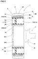
Fig. 2 ] is a meridional cross-section view. - [Fi g. 3] is a cross-secti on vi ew exaggeratingly showing a bondi ng porti on between a tread ring, a spoke and a hub.
- [
Figs. 4 ] (A) to (D) are conceptual developed views in the flat of an arraying state of a spoke board, where the spoke portion comprises spoke board row. - [
Figs. 5 ] (A) to (D) are conceptual developed views in the flat of a state of the spoke board, where the spoke portion comprises spoke board row extending continuously in the circumferential direction. - [
Figs. 6 ] (A) and (B) are partial cross-section views showing another embodiment of the first covering member. - [
Figs. 7 ] (A) and (B) are partial cross-section views showing another embodiment of the second covering member. - [
Figs. 8 ] (A) and (B) are cross-section views showing a molding process in a method for manufacturing of the ai rl ess tire according to the second invention. - Hereinafter, embodiments of the present inventions will be described in detail.
- As shown in
Figs. 1 and2 , anairless tire 1 according to the first invention comprises acylindrical tread ring 2 having a contact area S, ahub 3 disposed on the radially inner side of thetread ring 2 and fixed to an axle J, and aspoke 4 connecting thetread ring 2 with thehub 3. The present embodiment shows the case that theairless tire 1 is formed as a tire for a passenger vehicle. - The
tread ring 2 is a portion corresponding to a tread portion of a pneumatic tire and comprises atread rubber portion 2A and a reinforcingcord layer 2B buried therein. - For the
tread rubber portion 2A, rubber composition excelling in a frictional force to connecting ground and a wear resistance is preferably employed. And on the contact area S forming an inner peripheral surface of thetread ring 2, tread grooves (not shown) are formed in various pattern shapes to give wet performance. - The reinforcing
cord layer 2B of the present embodiment comprises abelt layer 5 and aband layer 6 superposed outside or inside in the radial direction of it. However, it is possible to form the rei nforcing cord layer 2B of only thebel t layer 5 or only theband layer 6. Thebelt layer 5 is formed of not less than one belt ply, twobelt plies tread ring 2. Theband layer 6 is formed of at least one band ply, one band ply in the present embodiment, having a tire cord helically winding in the circumferential direction of the ti re. - For the tire cord of the
belt layer 5 and the tire cord of theband layer 6, a steel cord and an organic fiber cord can be employed, respectively. When using the organic fiber cord, high-modulus fiber such as aramid, polyethylene naphthalate (PEN), polyethylene terephthalate (PET) having a high intensity and a high elastic modulus are preferably employed. - Such a
tread ring 2 is formed in a process for forming a raw tread ring and in a process for vulcanizing the raw tread ring in a vulcanizetion mold. In the forming process of the raw tread ring, sheet-like member for forming thebelt layer 5, a sheet-like member for forming theband layer 6, and a sheet-like member for forming thetread rubber portion 2A are serially wound on the cylindrical drum in the circumferential direction so as to form the raw tread ring. Then, the raw tread ring is vulcanized in the vulcanization mold so as to form the above-mentionedtread ring 2. - The
hub 3, which corresponds to a tire wheel in the present embodiment, comprises a disk-shaped disk portion 3A fixed to the axle J, and a cylindricalspoke attachiment portion 3B integrally formed in the radially outer end portion of thedisk portion 3A. In the center of thedisk portion 3A, a hub hole 3A1 is formed. Into this hub hole 3A1, inserted is a front end portion Ja of the axle J. And the periphery of the hub hole 3A1 is provided with plurality of bolt insertion holes 3A2. In each of the bolt insertion holes 3A2, a bolt portion Jb disposed on the axle side is inserted and fixed with a nut. Such ahub 3 is preferably formed of metallic material such as steal, aluminum alloy, magnesium alloy and the like, for example, as is the case with a conventional tire wheel. - The
spoke 4 is formed of cast molding body of high-polymer material. Thespoke 4 integrally comprises an outerannular portion 4A, an innerannular portion 4B, and aspoke portion 4C. For the high-polymer material, thermoplastic resin and thermohardening resin can be employed. with the objective of safety, thermohardeni ng resin such as epoxy-based resin, phenol-based resin, urethane-based resin, silicon-based resin, polyimide-based resin, melamine-based resin is preferably employed, for example. Especially, the urethane-based resin is preferably employed because of its excellent elastic property. - As shown in
Fig. 3 , the outerannular portion 4A is a cylindrical body which is concentric with the axle J. An outer peripheral surface 4AS of the outerannular portion 4A is bonded to an innerperipheral surface 2S of thetread ring 2 via afirst adhesion layer 21 made of first adhesive agent. The innerannular portion 4B is concentrically disposed in the radially inner side of the outerannular portion 4A. An inner peripheral surface 4BS of the innerannular portion 4B is bonded to an outerperipheral surface 3S of thehub 3 via asecond adhesion layer 22 made of the adhesive agent. Thespoke portion 4C integrally connects the outerannular portion 4A and the innerannular portion 4B. - As shown in
Fig. 1 , thespoke portion 4C of the present embodiment is formed of at least one spokeboard row 10R extending circumferentially. This spokeboard row 10R is formed by plurality of fin-like spoke boards 10 arranged in the circumferential direction and connecting between the outerannular portion 4A and the innerannular portion 4B. - Especially in the present embodiment, for the
spoke board row 10R, as shown inFig. 4 (A) , thespoke boards 10 are inclined at an angle θ (theta) with respect to the tire axial direction and arranged in parallel to each other. However, for thespoke row 10R, as shown inFig. 4 (B) , it is also possible to arrange alternately afirst spoke board 10a inclined at the angle θ (theta) toward one side with respect to the ti re axi al di recti on and asecond spoke board 10b inclined at the angle of θ (theta) toward the other side. Also shown inFig. 4 (C) , it is possible to form by two rows: a first spoke board row 10Ra made by arranging the first spokeboards 10a in parallel to each other, and a second spoke board row 10Rb made by arranging the second spoke board s 10b in parallel to each other. In this way, when thespoke board 10 is inclined at the angle θ (theta), the grounding time of thespoke board 10 gets longer; therefore a vibration performance of the tire can be improved. Meanwhile, the above-mentioned angle θ (theta) is preferably in a range of from 30 to 60 degrees although not particularly restricted. As shown inFig. 4(D) , it is also possible to form thespoke board row 10R by thespoke board 10 not inclined with respect to the tire axis direction (angle θ ≈ 0). - As shown in
Figs. 5 (A) to (D) , thespoke portion 4C can comprise acircumferential spoke board 12 extending continuously in the circumferential direction. InFigs. 5 (A) and 5 (B) , the circumferential spokeboard 12 circumferentially extends in a linear fashion. InFigs. 5 (C) and 5 (D) , the circumferential spokeboard 12 circumferentially extends in a zigzag manner. As shown inFig. 5 (D) by deputy, when thespoke portion 4C comprises the circumferential spokeboard 12, it is possible to provide aside plate portion 12e extending outward in the axial direction of the tire from thespoke board 12 to improve the rigidity. Specifically, when the circumferential spokeboard 12 is formed in the zigzag manner, theside plate portion 12e is preferably provided in a corner portion of the zigzag. - As shown in
Fig. 3 exaggeratingly, the innerperipheral surface 2S of thetread ring 2, where thefirst adhesion layer 21 is arranged, and/or the outer peripheral surface 3s of thehub 3, where thesecond adhesion layer 22 is arranged, is formed of a roughenedsurface 23. In the present embodiment, both of the innerperipheral surface 2S of thetread ring 2 and the outerperipheral surface 3S of thehub 3 are formed as the roughenedsurface 23. However, it is also possible that only either of them is formed as the roughenedsurface 23. The roughenedsurface 23 has a surface roughness Ra (arithmetic roughness) ranging from 3 to 1000 µm or a surface roughness Rz (ten-point average roughness) ranging from 30 to 5000 µm. - In this way, since the inner
peripheral surface 2S of thetread ring 2 and/or the outerperipheral surface 3S of thehub 3 is formed of the roughenedsurface 23, the contact area with the adhesive agent can be improved. Also the adhesive agent gets through and intertangles with the asperity of the roughenedsurface 23, thereby improving the bonding strength in cooperation with the increase of the contact area. - As a result, in cases where the inner
peripheral surface 2S is the roughenedsurface 23, even if a hit of sand and stone and the like and a contact with a curbstone while running cause a damage in the outer end of thefirst adhesion layer 21, it is possible to inhibit the growth of the damage, and i t is possible to reduce the flaking between thespoke 4 and thetread ring 2. In cases where the outerperipheral surface 3S is the roughenedsurface 23, even if damage generates in the outer end of thesecond adhesion layer 22, it is possible to inhibit the growth of the damage and to reduce the flaking between thespoke 4 and thehub 3. - Meanwhile, when the surface roughness Ra or Rz falls below the above-mentioned range, the enhancing effects of the bonding strength is insufficient, and the ti re durability cannot be sufficiently improved. By contraries, the surface roughness Ra or Rz exceeds the above-mentioned range, when the inner
peripheral surface 2S is the roughenedsurface 23, the salient of the roughenedsurface 23 as rubber runs into the outer peripheral surface of the outerannular portion 4A, and a strength of the outer peripheral surface of the outerannular portion 4A, thereby provoking possibly the deterioration of the ti re durability. Also, when the outerperipheral surface 3S is the roughenedsurface 23, strength of the hub itself deteriorates, thereby provoking possibly the deterioration of the strength of the hub itself during use. It is more preferably that the roughenedsurface 23 has both of the surface roughness Ra (arithmetic roughness) and the surface roughness Rz (ten-point average roughness) meeting the respective ranges. - Also, to inhibit more the deterioration of the durability arisen from the hit of sand and stone and the like and the contact with the curbstone while running, the
airless tire 1 of the present embodiment is provided with afirst covering member 24A and/or asecond covering member 24B. Thefirst covering member 24A covers and protects anouter end portion 21E in the vehicle mounting di recti on of the first adhesion layer 21. Also, thesecond covering member 24B covers and protects anouter end portion 22E in the vehicle mounting direction of thesecond adhesion layer 22. The present embodiment shows the case that both of thefirst covering member 24A and thesecond covering member 24B are disposed. However, there may be either of them. Meanwhile, the outer side in the vehicle mounting direction means the outward direction of the vehicle in the ti re axi al di recti on when the ti re is mounted on the vehicle. - The first and
second covering members outer end portions - As shown in
Fig. 3 , this embodiment shows the case that the first andsecond covering members tapes 25 applied on the outer side surface in the vehicle mounting direction of theairless tire 1. Thetapes 25 cover and protect theouter end portions tape 25 is not specifically restricted but commercially available various adhesion tapes where an adhesive agent is applied on one side of a film is preferably employed. For the film, for example, a film of synthetic resin such as polypropylene, polyester, polyethylene, vinyl chloride, nylon and the like are preferably employed in terms of the water resistance, durability and the like. However, for the film, cloth and sheet metal can be also employed upon request. - The first and
second covering members airless tire 1. For the film of paint, commercially available various coating materials are preferably employed. The film of paint is not necessary to be formed full part of the outer surface of theairless tire 1, but the width W may be not more than 10 mm, or not more than 5 mm for example, as long as it covers theouter end portions tape 25. The film of paint and thetape 25 have preferably a thickness of not more than 1.0 mm. When it exceeds 1.0 mm, a heat storage performance is improved, thereby provoking temperature increase while running and negatively affect to the durability of thespoke 4. - As shown in
Fig. 6 (A) , thefirst covering member 24A may be atread protruding portion 26 protruding in thetread ring 2. In particular, thistread protruding portion 26 protrudes radially inwardly at a level of the outer end of the innerperipheral surface 2S. And thetread protruding portion 26 has a projecting height from the innerperipheral surface 2S larger than the thickness of afirst adhesion layer 21 thereby enabling to cover theouter end portion 21E of thefirst adhesion layer 21. - As shown in
Fig. 6 (B) , thefirst covering member 24A may be aspoke protruding portion 27 protruding in the outerannular portion 4A of thespoke 4. Concretely, this spoke protrudingportion 27 radially outwardly protrudes at the level of the outer end of the outer peripheral surface of the outerannular portion 4A. And thespoke protruding portion 27 has a projecting height from the outer peripheral surface larger than the thickness of thefirst adhesion layer 21 thereby enabling to cover theouter end portion 21E of thefirst adhesion layer 21. In the present embodiment, thetread protruding portion 26 and thespoke protruding portion 27 are formed on the inner side and outer side in the vehicle mounting direction, respectively, but it is also acceptable to prove only on the outside in the vehicle mounting direction. - As shown in
Fig. 7 (A) , thesecond covering member 24B may be also ahub protruding portion 28 protruding in thehub 3. Concretely, thishub protruding portion 28 protrudes radially outwardly protrudes at the level of the outer end of the outer peripheral surface 3s. Thehub protruding portion 28 has a projecting height from the outerperipheral surface 3S larger than the thickness of thesecond adhesion layer 22 thereby enabling to cover theouter end portion 22E of thesecond adhesion layer 22. - As shown in
Fig. 7 (B) , thesecond covering member 24B may be aspoke protruding portion 29 protruding in the innerannular portion 4B of thespoke 4. Concretely, this spoke protrudingportion 29 radially inwardly protrudes at the level of the outer end of the inner peripheral surface of the innerannular portion 4B. And thespoke protruding portion 29 has a projecting height from the inner peripheral surface larger than the thickness of thesecond adhesion layer 22 thereby enabling to cover theouter end portion 22E of thesecond adhesion layer 22. In this embodiment, thehub protruding portion 28 and thespoke protruding portion 29 are formed on the inner side and outer side in the vehicle mounting direction, respectively, but it is also acceptable to prove only on the outside in the vehicle mounting direction. -
Figs. 6 (A) and (B) show the case of forming only thefirst covering member 24A;Figs. 7 (A) and (B) show the case of forming only thesecond covering member 24B. However, as is the case withFig. 3 , it is also possible to form both thefirst covering member 24A and thesecond covering member 24B. - Next, a method for manufacturing (according to the second invention) of the
airless tire 1 will be described. This method for manufacturing comprises a surface roughening process, a first coating process, a second coating process, and a molding process. - The surface roughening process comprises at least one of a surface roughening process to the
tread ring 2 and a surface roughening process to thehub 3. In the surface roughening process to thetread ring 2, a surface roughening is executed on the innerperipheral surface 2S of thetread ring 2 after vulcanization molding. As a result, the innerperipheral surface 2S is processed into the roughenedsurface 23 having the surface roughness Ra (arithmetic roughness) ranging from 3 to 1000 µm or the surface roughness Rz (ten-point average roughness) ranging from 30 to 5000 µm. Also in the surface roughening process to thehub 3, the outerperipheral surface 3S of thehub 3 is executed a surface roughening. As a result, the outer peripheral surface 3s is proceeded into the roughenedsurface 23 having the surface roughness Ra (arithmetic roughness) ranging from 3 to 1000 µm or the surface roughness Rz (ten-point average roughness) ranging from 30 to 5000 µm. - In the surface roughening, spraying and running particles such as metal, plastic, sand and the like onto a surface to be processed at high velocities, as it is called a blast process, is preferably employed. In this case, by making an adjustment of a particle diameter of the particle and a processing time, the above-mentioned range can be obtained.
- In the first coating process, applying the adhesive agent on the inner
peripheral surface 2S of thetread ring 2 forms thefirst adhesion layer 21. when the surface roughening process to treadring 2 is executed, thefirst adhesion layer 21 is formed on the inner peripheral surface 2s of the roughenedsurface 23. - In the second coating process, applying the adhesive agent on the outer
peripheral surface 3S of thehub 3 forms thesecond adhesion layer 22. when the surface roughening process to thehub 3 is executed, thesecond adhesion layer 22 is formed on the outerperipheral surface 3S of the roughenedsurface 23. - For the adhesive agent forming the first and second adhesion layers 21, 22, various kinds of adhesive agents such as latex type, solvent type, respondence type and the like can be appropriately chosen depending on quality of material of an adherend. In the present embodiment, the
first adhesion layer 21 and thesecond adhesion layer 22 are formed of the same adhesive agent, but also possibly formed of different adhesive agents, respectively. - As shown in
Figs. 8(A), (B) , in the molding process, thetread ring 2 provided in the innerperipheral surface 2 S with thefirst adhesion layer 21 and thehub 3 provided on the outerperipheral surface 3S with thesecond adhesion layer 22 are set in a castingmold 30. As a result, aspace 31 corresponding to thespoke 4 is formed inside this castingmold 30 and between thetread ring 2 and thehub 3. And, by filling the raw material fluid of the high-polymer material into thespace 31, thespoke 4 is integrally molded with thetread ring 2 and thehub 3. Meanwhile, the filling of the raw material fluid is performed before curing of the adhesive agent. - In this case, when the raw material fluid cures, the
first adhesion layer 21 and thespoke 4, and thesecond adhesion layer 22 and thespoke 4 react on each interfacial surface, thereby a strong bonding force is exerted. For example, when the urethane-based resin is used as the raw material fluid, it is preferable to use the adhesive agent such as "CHEMLOK 218E" (trademark) manufactured by LORD FAR EAST INC), which adheres the urethane-based resin and a hard adhered made of metal and others. In this case, chemical compound in the raw material fluid and chemical compound in the adhesive agent develop a cross-linking reaction and the like on the interfacial surface and join together, thereby a strong bonding force is executed. Therefore, the bonding strength is kept at a sufficiently high level between the fi rst and second adhesion layers 21, 22 and thespoke 4. However, a bonding strength between the fi rst adhesi onlayer 21 and the tread ri ng 2 and/or a bondi ng strength between thesecond adhesion layer 22 and thehub 3 is improved when the innerperipheral surface 2S of thering 2 and/or the outerperipheral surface 3S of thehub 3 is the roughenedsurface 23. - The preferred embodiments of the present inventions are especially discussed in detail, the present inventions are not limited to the illustrated embodiment, and various modifications can be modified.
- Based on the method for manufacturing according to the second invention, a test ti re passenger vehicle (corresponding to a ti re size: 145/70R12) having an internal structu re shown in
Fig. 1 was made in the specification shown in Tables 1 and 2. And after a molding process, a visual inspection was executed with regard to an adhesion condition of the spoke at the time of demolding the tire from the casting mold (adhesi on condi ti on i n demol di ng) . And regarding each of the test ti res, executed were a drum running test and an actual vehicle running test. In Table 1, the bondi ng strength of the bondi ng portion between the spoke and the tread ring was evaluated. In Table 2, the bonding strength of the bonding portion between the spoke and the hub was evaluated. - In each of the test tires, urethane-based resin was employed for the spoke, and the trade name "CHEMLOK 218E" (manufactured by LORD FAR EAST INC.) was employed for a first adhesion layer and a second adhesion layer. And in Table 1, a surface roughness of a hub outer peripheral surface of each tire was the same (Ra = 6.77 µm; Rz = 92.99 µm), and only a surface roughness of a tread ring inner peri pheral surface and a fi rst covering member was changed. In Table 2, a surface roughness of a tread ring inner peripheral surface of each tire was the same (Ra = 6.77 µm; Rz = 92.99 µm), and only the surface roughness of the hub outer peripheral surface and the second covering member was changed.
- (1) Drum running test:
- With use of a drum testing machine, a test tire ran 10000 km on a drum under a load of 3 kN and at a speed of 100 km/h. In Table 1, the adhesion condition in the bonding portion between the spoke and the tread ring after running was inspected visually. In Table 2, the adhesion condition in the bonding portion between the spoke and the hub after running was inspected visually.
- (2) Actual vehicle running test:
- The test tires were mounted on four wheels of a vehicle (extremely-compact EV: trade name "CMOS") and ran 10000 km on a road in an urban area. In Table 1, a damage state in the bonding portion between the spoke and the tread ring after running was inspected visually. In Table 2, a damage state in the bonding portion between the spoke and the hub after running was inspected visually.
- As shown in Table 1, even if a damage arose in the outer end of the adhesion layer by hit of a stone and the like while running, it was confirmed that Examples A1 to A11 could inhibit growth of the damage and reduce flaking between the spoke and the tread ring, thereby i mprovi ng a durability of the ti re. Specifically, when the ti re compri sed of the first covering member, it was confirmed that the generation of the damage itself in the adhesion layer outer end could be reduced. Also, in Example All, since the tape was thick, it was good in an ordinary use but carried a concern about a deterioration of strength of the spoke in long running or high-speed running owing to temperature elevation.


- As shown in Table 2, even if a damage arose in the outer end of the adhesion layer by hit of a stone and the like while running, it was confirmed that Examples B1 to B11 could inhibit growth of the damage and reduce flaking between the spoke and the hub, thereby improving a durability of the tire. Specifically, when the tire comprised of the second covering member, it was confirmed that the generation of the damage itself in the adhesion layer outer end could be reduced. Also, in Example B11, since the tape was thick, it was good in an ordinary use but carried a concern about a deterioration of strength of the spoke in long running or high-speed running owing to temperature elevation.
-
- 1
- Airless tire
- 2
- Tread ring
- 3
- Hub
- 4
- Spoke
- 4A
- Outer annular portion
- 4B
- Inner annular portion
- 4C
- Spoke portion
- 21
- First adhesion layer
- 22
- Second adhesion layer
- 23
- Roughened surface
- 24A
- First covering member
- 24B
- Second covering member
- 25
- Tape
- 26
- Tread ring protruding portion
- 27
- Spoke protruding portion
- 28
- Hub protruding portion
- 29
- Spoke protruding portion
- 30
- Casting mold
- 31
- Space
- J
- Axle
- S
- Contact area


Claims (10)
- An airless tire comprising
a cylindrical tread ring comprising a contact area,
a hub di sposed inwardly in the radial di recti on of the tread ri ng and fixed to an axle, and
a spoke connecting the tread ring and the hub; wherein
the spoke is formed of a cast molding body made of high-polymer material and comprises integrally
an outer annular portion of which outer peripheral surface is bonded on an inner peripheral surface of the tread ring via a first adhesion layer made of adhesive agent,
an inner annular portion of which inner peripheral surface is bonded on the outer peripheral surface of the hub via a second adhesion layer made of adhesive agent, and
a spoke porti on connecti ng the outer annul ar portion and the inner annular portion; and
the inner peripheral surface of the tread ring and/or the outer peripheral surface of the hub is formed as a roughened surface having a surface roughness Ra (arithmetic roughness) ranging from 3 to 1000 µm or a surface roughness Rz (ten-point average roughness) ranging from 30 to 5000 µm. - The ai rl ess ti re as set forth in claim 1 characteri zed in that the inner peripheral surface of the tread ring is formed of the roughened surface, and an outer end portion of the first adhesion layer in the vehicle mounting direction is covered by a first covering member.
- The airless tire as set forth in claim 1 or 2 characterized in that the outer peripheral surface of the hub is formed of the roughened surface, and an outer end portion of the second adhesion layer in the vehicle mounting direction is covered by a second covering member.
- The airless tire as set forth in claim 2 or 3 characterized in that the first covering member and/or the second covering member is a tape adhered to the outer side surface of the airless tire in the vehicle mounting direction.
- The airless tire as set forth in claim 2 or 3 characterized in that the first coveri ng member and/or the second coveri ng member is a coveri ng layer of paint applied on the outer side surface of the airless tire in the vehicle mounting direction.
- The airless tire as set forth in claim 2 characterized in that the first covering member is a tread protruding portion protruding in the tread ring.
- The airless tire as set forth in claim 2 characterized in that the first covering member is a spoke protruding portion protruding in the outer annular portion of the spoke.
- The airless tire as set forth in claim 3 characterized in that the second covering member is a hub protruding portion protruding in the hub.
- The airless tire as set forth in claim 3 characterized in that the second covering member is a spoke protruding portion protruding in the inner annular portion of the spoke.
- A method for manufacturing of the airless tire as set forth in claims 1 to 9, characterized in that the method for manufacturing comprises
a first coating process of applying the adhesive agent on the inner peripheral surface of the tread ri ng to form a fi rst adhesion layer,
a second coating process of applying the adhesive agent on the outer peripheral surface of the hub to form a second adhesion layer, and
a molding process comprising
a step of setti ng the tread ri ng and the hub wi th the adhesive agent in a casting mold to form space corresponding to the spoke between the tread ring and the hub, and
a step of filling raw material fluid of the high-polymer material into the space to form the spoke integrally with the tread ring and the hub; and
before the first coating process and/or the second coating process, a surface roughening process of roughening the inner peripheral surface of the tread ring and/or the outer peripheral surface of the hub is performed so that the inner peripheral surface and/or the outer peripheral surface has the surface roughness Ra (arithmetic roughness) ranging from 3 to 1000 µm or the surface roughness Rz (ten-point average roughness) ranging from 30 to 5000 µm.
Applications Claiming Priority (3)
| Application Number | Priority Date | Filing Date | Title |
|---|---|---|---|
| JP2013108281 | 2013-05-22 | ||
| JP2013108280 | 2013-05-22 | ||
| PCT/JP2014/062733 WO2014188912A1 (en) | 2013-05-22 | 2014-05-13 | Airless tire and method for manufacturing same |
Publications (3)
| Publication Number | Publication Date |
|---|---|
| EP3000619A1 true EP3000619A1 (en) | 2016-03-30 |
| EP3000619A4 EP3000619A4 (en) | 2017-02-22 |
| EP3000619B1 EP3000619B1 (en) | 2018-07-11 |
Family
ID=51933473
Family Applications (1)
| Application Number | Title | Priority Date | Filing Date |
|---|---|---|---|
| EP14800903.8A Active EP3000619B1 (en) | 2013-05-22 | 2014-05-13 | Airless tire and method for manufacturing same |
Country Status (5)
| Country | Link |
|---|---|
| US (1) | US9962994B2 (en) |
| EP (1) | EP3000619B1 (en) |
| JP (1) | JP6291489B2 (en) |
| CN (1) | CN105189143B (en) |
| WO (1) | WO2014188912A1 (en) |
Cited By (6)
| Publication number | Priority date | Publication date | Assignee | Title |
|---|---|---|---|---|
| EP3144160A4 (en) * | 2014-05-14 | 2017-11-15 | Sumitomo Rubber Industries, Ltd. | Airless tire and method of manufacturing same |
| CN109334351A (en) * | 2018-10-30 | 2019-02-15 | 济南奥美联亚工矿设备有限公司 | Polyurethane solid tyre and preparation method thereof |
| EP3666548A4 (en) * | 2017-08-09 | 2020-08-19 | Honda Motor Co., Ltd. | AIRLESS TIRE |
| EP3623174A4 (en) * | 2017-05-11 | 2020-11-18 | Bridgestone Corporation | AIRLESS TIRE |
| EP3789210A1 (en) * | 2019-09-06 | 2021-03-10 | Toyo Tire Corporation | Non-pneumatic tire |
| US20220072906A1 (en) * | 2019-01-04 | 2022-03-10 | Bridgestone Americas Tire Operations, Llc | Tire tread with a band layer |
Families Citing this family (44)
| Publication number | Priority date | Publication date | Assignee | Title |
|---|---|---|---|---|
| JP6242015B2 (en) * | 2012-12-26 | 2017-12-06 | 株式会社ブリヂストン | Non pneumatic tire |
| JP6051037B2 (en) * | 2012-12-26 | 2016-12-21 | 株式会社ブリヂストン | Non pneumatic tire |
| JP6212381B2 (en) * | 2013-12-24 | 2017-10-11 | 住友ゴム工業株式会社 | Airless tire |
| JP6302355B2 (en) * | 2014-05-22 | 2018-03-28 | 住友ゴム工業株式会社 | Non-pneumatic tire |
| JP2016113078A (en) * | 2014-12-17 | 2016-06-23 | 株式会社ブリヂストン | Non-pneumatic tire |
| JP6383294B2 (en) | 2015-01-13 | 2018-08-29 | 住友ゴム工業株式会社 | Airless tire |
| CN107107663A (en) * | 2015-01-15 | 2017-08-29 | 株式会社普利司通 | Non-inflatable tyre |
| EP3064371B1 (en) * | 2015-03-05 | 2020-04-29 | Sumitomo Rubber Industries, Ltd. | Airless tire |
| JP6408937B2 (en) * | 2015-03-05 | 2018-10-17 | 住友ゴム工業株式会社 | Airless tire |
| WO2017039604A1 (en) * | 2015-08-31 | 2017-03-09 | Compagnie Generale Des Etablissements Michelin | Non-pneumatic tire |
| WO2017116390A1 (en) * | 2015-12-28 | 2017-07-06 | Compagnie Generale Des Etablissements Michelin | Method of forming a support structure of a non-pneumatic tire |
| WO2017116825A1 (en) * | 2015-12-29 | 2017-07-06 | Bridgestone Americas Tire Operations, Llc | Composite layer tire |
| WO2017116454A1 (en) * | 2015-12-31 | 2017-07-06 | Compagnie Generale Des Etablissements Michelin | Non-pneumatic wheel |
| KR101789407B1 (en) * | 2016-02-26 | 2017-10-23 | 엘지전자 주식회사 | Robot cleaner and wheel assembly |
| JP6633948B2 (en) * | 2016-03-14 | 2020-01-22 | 本田技研工業株式会社 | Airless tire and its manufacturing apparatus and method |
| JP2019532859A (en) * | 2016-09-02 | 2019-11-14 | レイザー・ユーエスエー・エルエルシー | Airless tire |
| AU201711183S (en) * | 2016-09-02 | 2017-03-15 | Razor Usa Llc | Airless tire |
| JP2018058541A (en) * | 2016-10-07 | 2018-04-12 | 東洋ゴム工業株式会社 | Non-pneumatic tire and manufacturing method of the same |
| JP6834450B2 (en) * | 2016-12-15 | 2021-02-24 | 住友ゴム工業株式会社 | How to manufacture airless tires |
| JP6834635B2 (en) * | 2017-03-15 | 2021-02-24 | 住友ゴム工業株式会社 | How to manufacture airless tires and airless tires |
| CN106739821A (en) * | 2017-03-16 | 2017-05-31 | 青岛科技大学 | A kind of non-inflatable tyre of tyre surface combination belt |
| CN106827967B (en) * | 2017-04-05 | 2021-04-09 | 深圳市金特安科技有限公司 | Hollow structure tyre |
| JP6827880B2 (en) * | 2017-05-11 | 2021-02-10 | 株式会社ブリヂストン | Non-pneumatic tires |
| JP2018193046A (en) * | 2017-05-22 | 2018-12-06 | 株式会社ブリヂストン | Non-pneumatic tire |
| JP6965055B2 (en) | 2017-08-09 | 2021-11-10 | 本田技研工業株式会社 | Non-pneumatic tires |
| JP6978892B2 (en) * | 2017-10-23 | 2021-12-08 | 住友ゴム工業株式会社 | Airless tire complex |
| CN108162447B (en) * | 2018-01-31 | 2023-08-15 | 青岛海琅智能装备有限公司 | Split type non-pneumatic tire composite forming device and method |
| WO2020023235A1 (en) | 2018-07-27 | 2020-01-30 | Bridgestone Americas Tire Operations, Llc | Reusable rim for non-pneumatic tires |
| CN113195255B (en) | 2018-11-14 | 2024-01-19 | 普利司通美国轮胎运营有限责任公司 | Tire rim assembly having inner rim component and outer rim component |
| US12195624B2 (en) * | 2018-11-22 | 2025-01-14 | Bridgestone Corporation | Tire |
| EP3898274A4 (en) * | 2018-12-20 | 2022-10-05 | Bridgestone Americas Tire Operations, LLC | Splash control band for non-pneumatic tire |
| WO2020139680A1 (en) * | 2018-12-28 | 2020-07-02 | Bridgestone Americas Tire Operations, Llc | Web structure for non-pneumatic tire and method of making same |
| CN113226793A (en) * | 2018-12-28 | 2021-08-06 | 普利司通美国轮胎运营有限责任公司 | Non-pneumatic tire with reinforced outer ring |
| US12220953B2 (en) | 2019-01-04 | 2025-02-11 | Bridgestone Americas Tire Operations, Llc | Tire tread band with shim layers |
| JP7324088B2 (en) * | 2019-08-26 | 2023-08-09 | Toyo Tire株式会社 | non-pneumatic tires |
| JP7347008B2 (en) * | 2019-08-28 | 2023-09-20 | 住友ゴム工業株式会社 | tire |
| CN111619289A (en) * | 2020-06-04 | 2020-09-04 | 孙智勇 | Parcel type PU dual density tire |
| EP4200140B1 (en) * | 2020-08-18 | 2026-01-28 | Bridgestone Americas Tire Operations, LLC | Tire tread with a band layer |
| JP7552140B2 (en) * | 2020-08-19 | 2024-09-18 | 住友ゴム工業株式会社 | Airless tires |
| JP7497646B2 (en) * | 2020-08-19 | 2024-06-11 | 住友ゴム工業株式会社 | Airless tire manufacturing method |
| JP7497647B2 (en) * | 2020-08-19 | 2024-06-11 | 住友ゴム工業株式会社 | Airless tire manufacturing method |
| US11772416B2 (en) | 2020-10-06 | 2023-10-03 | The Goodyear Tire & Rubber Company | System for detection of non-pneumatic tire loading |
| JP7473492B2 (en) * | 2021-02-15 | 2024-04-23 | 中央発條株式会社 | Hair-implanted spring and its manufacturing method |
| JP7700467B2 (en) * | 2021-02-18 | 2025-07-01 | 住友ゴム工業株式会社 | Airless tires |
Family Cites Families (26)
| Publication number | Priority date | Publication date | Assignee | Title |
|---|---|---|---|---|
| US1885545A (en) | 1932-03-17 | 1932-11-01 | Rangel Felipe Rangel | Vehicle wheel |
| GB978913A (en) * | 1963-01-04 | 1965-01-01 | Robert Barnett | Improvements relating to wheels for vehicles |
| JPS58101803A (en) * | 1981-12-09 | 1983-06-17 | Sumitomo Rubber Ind Ltd | Solid type |
| US4832098A (en) | 1984-04-16 | 1989-05-23 | The Uniroyal Goodrich Tire Company | Non-pneumatic tire with supporting and cushioning members |
| AT394827B (en) * | 1985-10-16 | 1992-06-25 | Uniroyal Goodrich Tire Co | Tyre |
| DE8631175U1 (en) * | 1986-11-21 | 1987-04-02 | Heinrich Brandt Maschinenbau GmbH, 4920 Lemgo | Device for machining edges of plate-shaped workpieces |
| JPH06242Y2 (en) | 1987-03-31 | 1994-01-05 | 横浜ゴム株式会社 | Solid tire |
| US4934425A (en) * | 1988-03-23 | 1990-06-19 | Uniroyal Chemical Company, Inc. | Non-pneumatic tire |
| US5023040A (en) | 1988-03-23 | 1991-06-11 | Uniroyal Chemical Company, Inc. | Method of making a polyurethane non-pneumatic tire |
| CA2011473C (en) * | 1989-05-22 | 1998-01-06 | Richard L. Palinkas | Trapezoidal non-pneumatic tire with supporting and cushioning members |
| US4945962A (en) * | 1989-06-09 | 1990-08-07 | The Uniroyal Goodrich Tire Company | Honeycomb non-pneumatic tire with a single web on one side |
| US5265659A (en) * | 1992-03-18 | 1993-11-30 | Uniroyal Goodrich Licensing Services, Inc. | Non-pneumatic tire with ride-enhancing insert |
| US7650919B2 (en) | 1999-12-10 | 2010-01-26 | Michelin Recherche of Technique S.A. | Non-pneumatic tire having web spokes |
| JP4370152B2 (en) * | 2003-12-02 | 2009-11-25 | 株式会社前田シェルサービス | Recycled solid tire for snowy road and manufacturing method thereof |
| US7296860B2 (en) * | 2005-01-04 | 2007-11-20 | Adam Dangleman | Rim protector |
| JP4925627B2 (en) * | 2005-08-30 | 2012-05-09 | 越後工業株式会社 | Wheel |
| JP4316642B2 (en) * | 2007-12-19 | 2009-08-19 | 株式会社福永事務所 | Tires for vehicles |
| US8528991B2 (en) * | 2009-03-12 | 2013-09-10 | Raphael Schlanger | Vehicle wheel rim |
| US9662939B2 (en) * | 2009-07-28 | 2017-05-30 | Bridgestone Americas Tire Operations, Llc | Tension-based non-pneumatic tire |
| JP5394304B2 (en) * | 2010-04-12 | 2014-01-22 | 東洋ゴム工業株式会社 | Non-pneumatic tire and manufacturing method thereof |
| CN201696472U (en) * | 2010-05-26 | 2011-01-05 | 芜湖艾蔓设备工程有限公司 | Novel glue coating wheel |
| US20130139938A1 (en) | 2010-08-06 | 2013-06-06 | Bridgestone Corporation | Tire manufacturing method, tread member and tire |
| JP5743464B2 (en) * | 2010-09-14 | 2015-07-01 | 株式会社ブリヂストン | Pneumatic tire |
| EP3254868B1 (en) * | 2010-08-25 | 2019-08-14 | Bridgestone Corporation | Tire, and tire manufacturing method |
| US9573422B2 (en) * | 2012-03-15 | 2017-02-21 | Polaris Industries Inc. | Non-pneumatic tire |
| KR101411103B1 (en) * | 2013-11-06 | 2014-06-27 | 한국타이어 주식회사 | Non-pneumatic tire |
-
2014
- 2014-05-13 JP JP2015518194A patent/JP6291489B2/en active Active
- 2014-05-13 EP EP14800903.8A patent/EP3000619B1/en active Active
- 2014-05-13 CN CN201480025938.7A patent/CN105189143B/en active Active
- 2014-05-13 US US14/889,338 patent/US9962994B2/en active Active
- 2014-05-13 WO PCT/JP2014/062733 patent/WO2014188912A1/en not_active Ceased
Non-Patent Citations (1)
| Title |
|---|
| See references of WO2014188912A1 * |
Cited By (10)
| Publication number | Priority date | Publication date | Assignee | Title |
|---|---|---|---|---|
| EP3144160A4 (en) * | 2014-05-14 | 2017-11-15 | Sumitomo Rubber Industries, Ltd. | Airless tire and method of manufacturing same |
| US10259265B2 (en) | 2014-05-14 | 2019-04-16 | Sumitomo Rubber Industries, Ltd. | Airless tire and method of manufacturing same |
| EP3623174A4 (en) * | 2017-05-11 | 2020-11-18 | Bridgestone Corporation | AIRLESS TIRE |
| EP3666548A4 (en) * | 2017-08-09 | 2020-08-19 | Honda Motor Co., Ltd. | AIRLESS TIRE |
| CN109334351A (en) * | 2018-10-30 | 2019-02-15 | 济南奥美联亚工矿设备有限公司 | Polyurethane solid tyre and preparation method thereof |
| US20220072906A1 (en) * | 2019-01-04 | 2022-03-10 | Bridgestone Americas Tire Operations, Llc | Tire tread with a band layer |
| EP3906170A4 (en) * | 2019-01-04 | 2022-10-05 | Bridgestone Americas Tire Operations, LLC | TIRE TREAD WITH A TAPE LAYER |
| US11807052B2 (en) * | 2019-01-04 | 2023-11-07 | Bridgestone Americas Tire Operations, Llc | Tire tread with a band layer |
| EP3789210A1 (en) * | 2019-09-06 | 2021-03-10 | Toyo Tire Corporation | Non-pneumatic tire |
| US11654718B2 (en) | 2019-09-06 | 2023-05-23 | Toyo Tire Corporation | Non-pneumatic tire |
Also Published As
| Publication number | Publication date |
|---|---|
| US20160089935A1 (en) | 2016-03-31 |
| US9962994B2 (en) | 2018-05-08 |
| EP3000619B1 (en) | 2018-07-11 |
| CN105189143A (en) | 2015-12-23 |
| JP6291489B2 (en) | 2018-03-14 |
| EP3000619A4 (en) | 2017-02-22 |
| CN105189143B (en) | 2017-11-14 |
| JPWO2014188912A1 (en) | 2017-02-23 |
| WO2014188912A1 (en) | 2014-11-27 |
Similar Documents
| Publication | Publication Date | Title |
|---|---|---|
| EP3000619A1 (en) | Airless tire and method for manufacturing same | |
| JP5394304B2 (en) | Non-pneumatic tire and manufacturing method thereof | |
| CN110861449B (en) | Bionic non-inflatable wheel | |
| EP2100751B1 (en) | Rim made from composite material for a tubeless bicycle wheel and tubeless bicycle wheel comprising such a rim | |
| US10406860B2 (en) | Non-pneumatic tire | |
| CN102463856B (en) | Puncture sealant laminate | |
| KR20180054484A (en) | Non-pneumatic support structure | |
| KR102312792B1 (en) | Airless tire | |
| KR20150031246A (en) | An airless tyre for vehicles | |
| JP2018153932A (en) | Airless tire manufacturing method and airless tire | |
| JP6834450B2 (en) | How to manufacture airless tires | |
| US11958322B2 (en) | Non-pneumatic tire having reinforced support structure | |
| WO2015036815A1 (en) | Unitary wheel for ground service supporting equipment | |
| JP7783722B2 (en) | Method for manufacturing non-pneumatic tires | |
| JP4901148B2 (en) | Base for mounting electronic components and tire with pedestal | |
| US11491819B2 (en) | Non-pneumatic support structure | |
| US7913733B2 (en) | Composite tire assembly | |
| US20220371366A1 (en) | Non-pneumatic tire having multilayer spokes | |
| JP2002154302A (en) | Wheel for bicycle | |
| JP7723572B2 (en) | Method for manufacturing non-pneumatic tires | |
| US20240336094A1 (en) | Puncture resistant tires | |
| JP7790072B2 (en) | Airless tire and manufacturing method thereof | |
| WO2024091756A1 (en) | Flexure member for non-pneumatic tire spoke component | |
| KR102187261B1 (en) | Tire and method of manufacturing the tire | |
| EP4476076A1 (en) | Tire having cantilevered sidewall shape and flexible support ring structure |
Legal Events
| Date | Code | Title | Description |
|---|---|---|---|
| PUAI | Public reference made under article 153(3) epc to a published international application that has entered the european phase |
Free format text: ORIGINAL CODE: 0009012 |
|
| 17P | Request for examination filed |
Effective date: 20151124 |
|
| AK | Designated contracting states |
Kind code of ref document: A1 Designated state(s): AL AT BE BG CH CY CZ DE DK EE ES FI FR GB GR HR HU IE IS IT LI LT LU LV MC MK MT NL NO PL PT RO RS SE SI SK SM TR |
|
| AX | Request for extension of the european patent |
Extension state: BA ME |
|
| DAX | Request for extension of the european patent (deleted) | ||
| A4 | Supplementary search report drawn up and despatched |
Effective date: 20170125 |
|
| RIC1 | Information provided on ipc code assigned before grant |
Ipc: B60C 7/00 20060101AFI20170119BHEP Ipc: B29D 99/00 20100101ALI20170119BHEP Ipc: B29D 30/00 20060101ALI20170119BHEP Ipc: B60C 7/12 20060101ALI20170119BHEP Ipc: B60C 7/14 20060101ALI20170119BHEP Ipc: B60C 7/18 20060101ALI20170119BHEP Ipc: B29D 30/02 20060101ALI20170119BHEP |
|
| GRAP | Despatch of communication of intention to grant a patent |
Free format text: ORIGINAL CODE: EPIDOSNIGR1 |
|
| STAA | Information on the status of an ep patent application or granted ep patent |
Free format text: STATUS: GRANT OF PATENT IS INTENDED |
|
| INTG | Intention to grant announced |
Effective date: 20171204 |
|
| GRAS | Grant fee paid |
Free format text: ORIGINAL CODE: EPIDOSNIGR3 |
|
| GRAA | (expected) grant |
Free format text: ORIGINAL CODE: 0009210 |
|
| STAA | Information on the status of an ep patent application or granted ep patent |
Free format text: STATUS: THE PATENT HAS BEEN GRANTED |
|
| AK | Designated contracting states |
Kind code of ref document: B1 Designated state(s): AL AT BE BG CH CY CZ DE DK EE ES FI FR GB GR HR HU IE IS IT LI LT LU LV MC MK MT NL NO PL PT RO RS SE SI SK SM TR |
|
| REG | Reference to a national code |
Ref country code: GB Ref legal event code: FG4D |
|
| REG | Reference to a national code |
Ref country code: CH Ref legal event code: EP |
|
| REG | Reference to a national code |
Ref country code: AT Ref legal event code: REF Ref document number: 1016478 Country of ref document: AT Kind code of ref document: T Effective date: 20180715 |
|
| REG | Reference to a national code |
Ref country code: IE Ref legal event code: FG4D |
|
| REG | Reference to a national code |
Ref country code: DE Ref legal event code: R096 Ref document number: 602014028411 Country of ref document: DE |
|
| REG | Reference to a national code |
Ref country code: NL Ref legal event code: MP Effective date: 20180711 |
|
| REG | Reference to a national code |
Ref country code: LT Ref legal event code: MG4D |
|
| REG | Reference to a national code |
Ref country code: AT Ref legal event code: MK05 Ref document number: 1016478 Country of ref document: AT Kind code of ref document: T Effective date: 20180711 |
|
| PG25 | Lapsed in a contracting state [announced via postgrant information from national office to epo] |
Ref country code: NL Free format text: LAPSE BECAUSE OF FAILURE TO SUBMIT A TRANSLATION OF THE DESCRIPTION OR TO PAY THE FEE WITHIN THE PRESCRIBED TIME-LIMIT Effective date: 20180711 |
|
| PG25 | Lapsed in a contracting state [announced via postgrant information from national office to epo] |
Ref country code: FI Free format text: LAPSE BECAUSE OF FAILURE TO SUBMIT A TRANSLATION OF THE DESCRIPTION OR TO PAY THE FEE WITHIN THE PRESCRIBED TIME-LIMIT Effective date: 20180711 Ref country code: PL Free format text: LAPSE BECAUSE OF FAILURE TO SUBMIT A TRANSLATION OF THE DESCRIPTION OR TO PAY THE FEE WITHIN THE PRESCRIBED TIME-LIMIT Effective date: 20180711 Ref country code: LT Free format text: LAPSE BECAUSE OF FAILURE TO SUBMIT A TRANSLATION OF THE DESCRIPTION OR TO PAY THE FEE WITHIN THE PRESCRIBED TIME-LIMIT Effective date: 20180711 Ref country code: BG Free format text: LAPSE BECAUSE OF FAILURE TO SUBMIT A TRANSLATION OF THE DESCRIPTION OR TO PAY THE FEE WITHIN THE PRESCRIBED TIME-LIMIT Effective date: 20181011 Ref country code: NO Free format text: LAPSE BECAUSE OF FAILURE TO SUBMIT A TRANSLATION OF THE DESCRIPTION OR TO PAY THE FEE WITHIN THE PRESCRIBED TIME-LIMIT Effective date: 20181011 Ref country code: GR Free format text: LAPSE BECAUSE OF FAILURE TO SUBMIT A TRANSLATION OF THE DESCRIPTION OR TO PAY THE FEE WITHIN THE PRESCRIBED TIME-LIMIT Effective date: 20181012 Ref country code: AT Free format text: LAPSE BECAUSE OF FAILURE TO SUBMIT A TRANSLATION OF THE DESCRIPTION OR TO PAY THE FEE WITHIN THE PRESCRIBED TIME-LIMIT Effective date: 20180711 Ref country code: IS Free format text: LAPSE BECAUSE OF FAILURE TO SUBMIT A TRANSLATION OF THE DESCRIPTION OR TO PAY THE FEE WITHIN THE PRESCRIBED TIME-LIMIT Effective date: 20181111 Ref country code: RS Free format text: LAPSE BECAUSE OF FAILURE TO SUBMIT A TRANSLATION OF THE DESCRIPTION OR TO PAY THE FEE WITHIN THE PRESCRIBED TIME-LIMIT Effective date: 20180711 Ref country code: SE Free format text: LAPSE BECAUSE OF FAILURE TO SUBMIT A TRANSLATION OF THE DESCRIPTION OR TO PAY THE FEE WITHIN THE PRESCRIBED TIME-LIMIT Effective date: 20180711 |
|
| PG25 | Lapsed in a contracting state [announced via postgrant information from national office to epo] |
Ref country code: ES Free format text: LAPSE BECAUSE OF FAILURE TO SUBMIT A TRANSLATION OF THE DESCRIPTION OR TO PAY THE FEE WITHIN THE PRESCRIBED TIME-LIMIT Effective date: 20180711 Ref country code: AL Free format text: LAPSE BECAUSE OF FAILURE TO SUBMIT A TRANSLATION OF THE DESCRIPTION OR TO PAY THE FEE WITHIN THE PRESCRIBED TIME-LIMIT Effective date: 20180711 Ref country code: HR Free format text: LAPSE BECAUSE OF FAILURE TO SUBMIT A TRANSLATION OF THE DESCRIPTION OR TO PAY THE FEE WITHIN THE PRESCRIBED TIME-LIMIT Effective date: 20180711 Ref country code: LV Free format text: LAPSE BECAUSE OF FAILURE TO SUBMIT A TRANSLATION OF THE DESCRIPTION OR TO PAY THE FEE WITHIN THE PRESCRIBED TIME-LIMIT Effective date: 20180711 |
|
| REG | Reference to a national code |
Ref country code: DE Ref legal event code: R097 Ref document number: 602014028411 Country of ref document: DE |
|
| PG25 | Lapsed in a contracting state [announced via postgrant information from national office to epo] |
Ref country code: IT Free format text: LAPSE BECAUSE OF FAILURE TO SUBMIT A TRANSLATION OF THE DESCRIPTION OR TO PAY THE FEE WITHIN THE PRESCRIBED TIME-LIMIT Effective date: 20180711 Ref country code: EE Free format text: LAPSE BECAUSE OF FAILURE TO SUBMIT A TRANSLATION OF THE DESCRIPTION OR TO PAY THE FEE WITHIN THE PRESCRIBED TIME-LIMIT Effective date: 20180711 Ref country code: RO Free format text: LAPSE BECAUSE OF FAILURE TO SUBMIT A TRANSLATION OF THE DESCRIPTION OR TO PAY THE FEE WITHIN THE PRESCRIBED TIME-LIMIT Effective date: 20180711 Ref country code: CZ Free format text: LAPSE BECAUSE OF FAILURE TO SUBMIT A TRANSLATION OF THE DESCRIPTION OR TO PAY THE FEE WITHIN THE PRESCRIBED TIME-LIMIT Effective date: 20180711 |
|
| PLBE | No opposition filed within time limit |
Free format text: ORIGINAL CODE: 0009261 |
|
| STAA | Information on the status of an ep patent application or granted ep patent |
Free format text: STATUS: NO OPPOSITION FILED WITHIN TIME LIMIT |
|
| PG25 | Lapsed in a contracting state [announced via postgrant information from national office to epo] |
Ref country code: DK Free format text: LAPSE BECAUSE OF FAILURE TO SUBMIT A TRANSLATION OF THE DESCRIPTION OR TO PAY THE FEE WITHIN THE PRESCRIBED TIME-LIMIT Effective date: 20180711 Ref country code: SK Free format text: LAPSE BECAUSE OF FAILURE TO SUBMIT A TRANSLATION OF THE DESCRIPTION OR TO PAY THE FEE WITHIN THE PRESCRIBED TIME-LIMIT Effective date: 20180711 Ref country code: SM Free format text: LAPSE BECAUSE OF FAILURE TO SUBMIT A TRANSLATION OF THE DESCRIPTION OR TO PAY THE FEE WITHIN THE PRESCRIBED TIME-LIMIT Effective date: 20180711 |
|
| 26N | No opposition filed |
Effective date: 20190412 |
|
| PG25 | Lapsed in a contracting state [announced via postgrant information from national office to epo] |
Ref country code: SI Free format text: LAPSE BECAUSE OF FAILURE TO SUBMIT A TRANSLATION OF THE DESCRIPTION OR TO PAY THE FEE WITHIN THE PRESCRIBED TIME-LIMIT Effective date: 20180711 |
|
| REG | Reference to a national code |
Ref country code: CH Ref legal event code: PL |
|
| GBPC | Gb: european patent ceased through non-payment of renewal fee |
Effective date: 20190513 |
|
| PG25 | Lapsed in a contracting state [announced via postgrant information from national office to epo] |
Ref country code: LI Free format text: LAPSE BECAUSE OF NON-PAYMENT OF DUE FEES Effective date: 20190531 Ref country code: MC Free format text: LAPSE BECAUSE OF FAILURE TO SUBMIT A TRANSLATION OF THE DESCRIPTION OR TO PAY THE FEE WITHIN THE PRESCRIBED TIME-LIMIT Effective date: 20180711 Ref country code: CH Free format text: LAPSE BECAUSE OF NON-PAYMENT OF DUE FEES Effective date: 20190531 |
|
| REG | Reference to a national code |
Ref country code: BE Ref legal event code: MM Effective date: 20190531 |
|
| PG25 | Lapsed in a contracting state [announced via postgrant information from national office to epo] |
Ref country code: LU Free format text: LAPSE BECAUSE OF NON-PAYMENT OF DUE FEES Effective date: 20190513 |
|
| PG25 | Lapsed in a contracting state [announced via postgrant information from national office to epo] |
Ref country code: TR Free format text: LAPSE BECAUSE OF FAILURE TO SUBMIT A TRANSLATION OF THE DESCRIPTION OR TO PAY THE FEE WITHIN THE PRESCRIBED TIME-LIMIT Effective date: 20180711 |
|
| PG25 | Lapsed in a contracting state [announced via postgrant information from national office to epo] |
Ref country code: GB Free format text: LAPSE BECAUSE OF NON-PAYMENT OF DUE FEES Effective date: 20190513 Ref country code: IE Free format text: LAPSE BECAUSE OF NON-PAYMENT OF DUE FEES Effective date: 20190513 |
|
| PG25 | Lapsed in a contracting state [announced via postgrant information from national office to epo] |
Ref country code: BE Free format text: LAPSE BECAUSE OF NON-PAYMENT OF DUE FEES Effective date: 20190531 |
|
| PG25 | Lapsed in a contracting state [announced via postgrant information from national office to epo] |
Ref country code: PT Free format text: LAPSE BECAUSE OF FAILURE TO SUBMIT A TRANSLATION OF THE DESCRIPTION OR TO PAY THE FEE WITHIN THE PRESCRIBED TIME-LIMIT Effective date: 20181111 |
|
| PG25 | Lapsed in a contracting state [announced via postgrant information from national office to epo] |
Ref country code: CY Free format text: LAPSE BECAUSE OF FAILURE TO SUBMIT A TRANSLATION OF THE DESCRIPTION OR TO PAY THE FEE WITHIN THE PRESCRIBED TIME-LIMIT Effective date: 20180711 |
|
| PG25 | Lapsed in a contracting state [announced via postgrant information from national office to epo] |
Ref country code: HU Free format text: LAPSE BECAUSE OF FAILURE TO SUBMIT A TRANSLATION OF THE DESCRIPTION OR TO PAY THE FEE WITHIN THE PRESCRIBED TIME-LIMIT; INVALID AB INITIO Effective date: 20140513 Ref country code: MT Free format text: LAPSE BECAUSE OF FAILURE TO SUBMIT A TRANSLATION OF THE DESCRIPTION OR TO PAY THE FEE WITHIN THE PRESCRIBED TIME-LIMIT Effective date: 20180711 |
|
| PG25 | Lapsed in a contracting state [announced via postgrant information from national office to epo] |
Ref country code: MK Free format text: LAPSE BECAUSE OF FAILURE TO SUBMIT A TRANSLATION OF THE DESCRIPTION OR TO PAY THE FEE WITHIN THE PRESCRIBED TIME-LIMIT Effective date: 20180711 |
|
| REG | Reference to a national code |
Ref country code: FR Ref legal event code: PLFP Year of fee payment: 10 |
|
| P01 | Opt-out of the competence of the unified patent court (upc) registered |
Effective date: 20230510 |
|
| PGFP | Annual fee paid to national office [announced via postgrant information from national office to epo] |
Ref country code: DE Payment date: 20250402 Year of fee payment: 12 |
|
| PGFP | Annual fee paid to national office [announced via postgrant information from national office to epo] |
Ref country code: FR Payment date: 20250401 Year of fee payment: 12 |