EP3000585A1 - Verfahren und gerät zum zusammenfügen von blasenteilen - Google Patents
Verfahren und gerät zum zusammenfügen von blasenteilen Download PDFInfo
- Publication number
- EP3000585A1 EP3000585A1 EP15186280.2A EP15186280A EP3000585A1 EP 3000585 A1 EP3000585 A1 EP 3000585A1 EP 15186280 A EP15186280 A EP 15186280A EP 3000585 A1 EP3000585 A1 EP 3000585A1
- Authority
- EP
- European Patent Office
- Prior art keywords
- mandrel
- piece
- inflatable device
- strip
- band
- Prior art date
- Legal status (The legal status is an assumption and is not a legal conclusion. Google has not performed a legal analysis and makes no representation as to the accuracy of the status listed.)
- Granted
Links
Images

Classifications
-
- B—PERFORMING OPERATIONS; TRANSPORTING
- B29—WORKING OF PLASTICS; WORKING OF SUBSTANCES IN A PLASTIC STATE IN GENERAL
- B29C—SHAPING OR JOINING OF PLASTICS; SHAPING OF MATERIAL IN A PLASTIC STATE, NOT OTHERWISE PROVIDED FOR; AFTER-TREATMENT OF THE SHAPED PRODUCTS, e.g. REPAIRING
- B29C65/00—Joining or sealing of preformed parts, e.g. welding of plastics materials; Apparatus therefor
- B29C65/48—Joining or sealing of preformed parts, e.g. welding of plastics materials; Apparatus therefor using adhesives, i.e. using supplementary joining material; solvent bonding
-
- B—PERFORMING OPERATIONS; TRANSPORTING
- B29—WORKING OF PLASTICS; WORKING OF SUBSTANCES IN A PLASTIC STATE IN GENERAL
- B29C—SHAPING OR JOINING OF PLASTICS; SHAPING OF MATERIAL IN A PLASTIC STATE, NOT OTHERWISE PROVIDED FOR; AFTER-TREATMENT OF THE SHAPED PRODUCTS, e.g. REPAIRING
- B29C65/00—Joining or sealing of preformed parts, e.g. welding of plastics materials; Apparatus therefor
- B29C65/78—Means for handling the parts to be joined, e.g. for making containers or hollow articles, e.g. means for handling sheets, plates, web-like materials, tubular articles, hollow articles or elements to be joined therewith; Means for discharging the joined articles from the joining apparatus
- B29C65/7802—Positioning the parts to be joined, e.g. aligning, indexing or centring
- B29C65/7832—Positioning the parts to be joined, e.g. aligning, indexing or centring by setting the overlap between the parts to be joined, e.g. the overlap between sheets, plates or web-like materials
-
- B—PERFORMING OPERATIONS; TRANSPORTING
- B29—WORKING OF PLASTICS; WORKING OF SUBSTANCES IN A PLASTIC STATE IN GENERAL
- B29C—SHAPING OR JOINING OF PLASTICS; SHAPING OF MATERIAL IN A PLASTIC STATE, NOT OTHERWISE PROVIDED FOR; AFTER-TREATMENT OF THE SHAPED PRODUCTS, e.g. REPAIRING
- B29C66/00—General aspects of processes or apparatus for joining preformed parts
- B29C66/01—General aspects dealing with the joint area or with the area to be joined
- B29C66/05—Particular design of joint configurations
- B29C66/10—Particular design of joint configurations particular design of the joint cross-sections
- B29C66/11—Joint cross-sections comprising a single joint-segment, i.e. one of the parts to be joined comprising a single joint-segment in the joint cross-section
- B29C66/112—Single lapped joints
- B29C66/1122—Single lap to lap joints, i.e. overlap joints
-
- B—PERFORMING OPERATIONS; TRANSPORTING
- B29—WORKING OF PLASTICS; WORKING OF SUBSTANCES IN A PLASTIC STATE IN GENERAL
- B29C—SHAPING OR JOINING OF PLASTICS; SHAPING OF MATERIAL IN A PLASTIC STATE, NOT OTHERWISE PROVIDED FOR; AFTER-TREATMENT OF THE SHAPED PRODUCTS, e.g. REPAIRING
- B29C66/00—General aspects of processes or apparatus for joining preformed parts
- B29C66/50—General aspects of joining tubular articles; General aspects of joining long products, i.e. bars or profiled elements; General aspects of joining single elements to tubular articles, hollow articles or bars; General aspects of joining several hollow-preforms to form hollow or tubular articles
- B29C66/51—Joining tubular articles, profiled elements or bars; Joining single elements to tubular articles, hollow articles or bars; Joining several hollow-preforms to form hollow or tubular articles
- B29C66/54—Joining several hollow-preforms, e.g. half-shells, to form hollow articles, e.g. for making balls, containers; Joining several hollow-preforms, e.g. half-cylinders, to form tubular articles
-
- B—PERFORMING OPERATIONS; TRANSPORTING
- B29—WORKING OF PLASTICS; WORKING OF SUBSTANCES IN A PLASTIC STATE IN GENERAL
- B29C—SHAPING OR JOINING OF PLASTICS; SHAPING OF MATERIAL IN A PLASTIC STATE, NOT OTHERWISE PROVIDED FOR; AFTER-TREATMENT OF THE SHAPED PRODUCTS, e.g. REPAIRING
- B29C66/00—General aspects of processes or apparatus for joining preformed parts
- B29C66/70—General aspects of processes or apparatus for joining preformed parts characterised by the composition, physical properties or the structure of the material of the parts to be joined; Joining with non-plastics material
- B29C66/71—General aspects of processes or apparatus for joining preformed parts characterised by the composition, physical properties or the structure of the material of the parts to be joined; Joining with non-plastics material characterised by the composition of the plastics material of the parts to be joined
-
- B—PERFORMING OPERATIONS; TRANSPORTING
- B29—WORKING OF PLASTICS; WORKING OF SUBSTANCES IN A PLASTIC STATE IN GENERAL
- B29C—SHAPING OR JOINING OF PLASTICS; SHAPING OF MATERIAL IN A PLASTIC STATE, NOT OTHERWISE PROVIDED FOR; AFTER-TREATMENT OF THE SHAPED PRODUCTS, e.g. REPAIRING
- B29C66/00—General aspects of processes or apparatus for joining preformed parts
- B29C66/80—General aspects of machine operations or constructions and parts thereof
- B29C66/81—General aspects of the pressing elements, i.e. the elements applying pressure on the parts to be joined in the area to be joined, e.g. the welding jaws or clamps
- B29C66/814—General aspects of the pressing elements, i.e. the elements applying pressure on the parts to be joined in the area to be joined, e.g. the welding jaws or clamps characterised by the design of the pressing elements, e.g. of the welding jaws or clamps
- B29C66/8145—General aspects of the pressing elements, i.e. the elements applying pressure on the parts to be joined in the area to be joined, e.g. the welding jaws or clamps characterised by the design of the pressing elements, e.g. of the welding jaws or clamps characterised by the constructional aspects of the pressing elements, e.g. of the welding jaws or clamps
- B29C66/81455—General aspects of the pressing elements, i.e. the elements applying pressure on the parts to be joined in the area to be joined, e.g. the welding jaws or clamps characterised by the design of the pressing elements, e.g. of the welding jaws or clamps characterised by the constructional aspects of the pressing elements, e.g. of the welding jaws or clamps being a fluid inflatable bag or bladder, a diaphragm or a vacuum bag for applying isostatic pressure
-
- B—PERFORMING OPERATIONS; TRANSPORTING
- B29—WORKING OF PLASTICS; WORKING OF SUBSTANCES IN A PLASTIC STATE IN GENERAL
- B29C—SHAPING OR JOINING OF PLASTICS; SHAPING OF MATERIAL IN A PLASTIC STATE, NOT OTHERWISE PROVIDED FOR; AFTER-TREATMENT OF THE SHAPED PRODUCTS, e.g. REPAIRING
- B29C67/00—Shaping techniques not covered by groups B29C39/00 - B29C65/00, B29C70/00 or B29C73/00
- B29C67/0014—Shaping techniques not covered by groups B29C39/00 - B29C65/00, B29C70/00 or B29C73/00 for shaping tubes or blown tubular films
- B29C67/0018—Turning tubes inside out
-
- B—PERFORMING OPERATIONS; TRANSPORTING
- B29—WORKING OF PLASTICS; WORKING OF SUBSTANCES IN A PLASTIC STATE IN GENERAL
- B29D—PRODUCING PARTICULAR ARTICLES FROM PLASTICS OR FROM SUBSTANCES IN A PLASTIC STATE
- B29D22/00—Producing hollow articles
- B29D22/02—Inflatable articles
-
- B—PERFORMING OPERATIONS; TRANSPORTING
- B29—WORKING OF PLASTICS; WORKING OF SUBSTANCES IN A PLASTIC STATE IN GENERAL
- B29C—SHAPING OR JOINING OF PLASTICS; SHAPING OF MATERIAL IN A PLASTIC STATE, NOT OTHERWISE PROVIDED FOR; AFTER-TREATMENT OF THE SHAPED PRODUCTS, e.g. REPAIRING
- B29C53/00—Shaping by bending, folding, twisting, straightening or flattening; Apparatus therefor
- B29C53/02—Bending or folding
- B29C53/025—Bending or folding using a folding bag
-
- B—PERFORMING OPERATIONS; TRANSPORTING
- B29—WORKING OF PLASTICS; WORKING OF SUBSTANCES IN A PLASTIC STATE IN GENERAL
- B29C—SHAPING OR JOINING OF PLASTICS; SHAPING OF MATERIAL IN A PLASTIC STATE, NOT OTHERWISE PROVIDED FOR; AFTER-TREATMENT OF THE SHAPED PRODUCTS, e.g. REPAIRING
- B29C57/00—Shaping of tube ends, e.g. flanging, belling or closing; Apparatus therefor, e.g. collapsible mandrels
-
- B—PERFORMING OPERATIONS; TRANSPORTING
- B29—WORKING OF PLASTICS; WORKING OF SUBSTANCES IN A PLASTIC STATE IN GENERAL
- B29C—SHAPING OR JOINING OF PLASTICS; SHAPING OF MATERIAL IN A PLASTIC STATE, NOT OTHERWISE PROVIDED FOR; AFTER-TREATMENT OF THE SHAPED PRODUCTS, e.g. REPAIRING
- B29C66/00—General aspects of processes or apparatus for joining preformed parts
- B29C66/01—General aspects dealing with the joint area or with the area to be joined
- B29C66/05—Particular design of joint configurations
- B29C66/10—Particular design of joint configurations particular design of the joint cross-sections
- B29C66/11—Joint cross-sections comprising a single joint-segment, i.e. one of the parts to be joined comprising a single joint-segment in the joint cross-section
- B29C66/112—Single lapped joints
-
- B—PERFORMING OPERATIONS; TRANSPORTING
- B29—WORKING OF PLASTICS; WORKING OF SUBSTANCES IN A PLASTIC STATE IN GENERAL
- B29C—SHAPING OR JOINING OF PLASTICS; SHAPING OF MATERIAL IN A PLASTIC STATE, NOT OTHERWISE PROVIDED FOR; AFTER-TREATMENT OF THE SHAPED PRODUCTS, e.g. REPAIRING
- B29C66/00—General aspects of processes or apparatus for joining preformed parts
- B29C66/01—General aspects dealing with the joint area or with the area to be joined
- B29C66/05—Particular design of joint configurations
- B29C66/10—Particular design of joint configurations particular design of the joint cross-sections
- B29C66/13—Single flanged joints; Fin-type joints; Single hem joints; Edge joints; Interpenetrating fingered joints; Other specific particular designs of joint cross-sections not provided for in groups B29C66/11 - B29C66/12
- B29C66/135—Single hemmed joints, i.e. one of the parts to be joined being hemmed in the joint area
-
- B—PERFORMING OPERATIONS; TRANSPORTING
- B29—WORKING OF PLASTICS; WORKING OF SUBSTANCES IN A PLASTIC STATE IN GENERAL
- B29C—SHAPING OR JOINING OF PLASTICS; SHAPING OF MATERIAL IN A PLASTIC STATE, NOT OTHERWISE PROVIDED FOR; AFTER-TREATMENT OF THE SHAPED PRODUCTS, e.g. REPAIRING
- B29C66/00—General aspects of processes or apparatus for joining preformed parts
- B29C66/50—General aspects of joining tubular articles; General aspects of joining long products, i.e. bars or profiled elements; General aspects of joining single elements to tubular articles, hollow articles or bars; General aspects of joining several hollow-preforms to form hollow or tubular articles
- B29C66/63—Internally supporting the article during joining
-
- B—PERFORMING OPERATIONS; TRANSPORTING
- B29—WORKING OF PLASTICS; WORKING OF SUBSTANCES IN A PLASTIC STATE IN GENERAL
- B29L—INDEXING SCHEME ASSOCIATED WITH SUBCLASS B29C, RELATING TO PARTICULAR ARTICLES
- B29L2022/00—Hollow articles
- B29L2022/02—Inflatable articles
- B29L2022/025—Bladders
Definitions
- the present application relates to a method and apparatus for producing a bladder.
- It relates more particularly to a method and apparatus for assembling a bladder composed of at least two parts.
- Such a bladder is for example intended to be filled with gas, such as nitrogen, and to be arranged in a fluid circuit, for example a hydraulic circuit, for example in a battery.
- gas such as nitrogen
- a bladder is often made of two or more parts formed of a flexible elastomer material. Two parts are then assembled by gluing in a bevelled peripheral zone, then vulcanized.
- the assembly of parts constituting a bladder for vulcanization bonding is performed manually, by one or more operators, and mainly consists in turning a first part, such as a sock, for example a lower part of the bladder , and forming a lapel at the edge thereof for a beveled and glued peripheral band is found facing outwards, then to position a beveled and glued peripheral band of a second part, for example a top piece, on the band of the first piece.
- a first part such as a sock, for example a lower part of the bladder
- an operator is generally obliged to put his fingers on the gluing planes, which can cause pollution and a risk of bladder assembly defects, such as an inhomogeneous assembly and / or fluctuation a state of stress in at least one of the component parts of the bladder.
- assembly defects may result, during the use of the bladder, by gas leaks at the collages, which pollutes the hydraulic circuit and makes the accumulator unusable.
- At least one of the objectives of the present application is thus to solve, at least in part, the aforementioned drawbacks, leading in addition to other advantages.
- the method comprises a step of positioning two parts of the bladder to be assembled relative to each other, then a step of turning at least one glued strip of one of the two parts by means of the inflatable device axisymmetric annular.
- annular axisymmetric inflatable device may designate a simple torus, when it is formed of a single inflatable cavity; alternatively, it may be formed of a circumferential plurality of elongate or at least approximately spherical cavities (it will be understood that, in order to obtain the effect of turning the periphery of one band over the other, it is necessary to a number of cavities all the greater in that they have a small circumferential dimension, in fact these cavities are in practice approximately contiguous).
- At least one of the pieces is then returned as a sock, that is to say placed upside down, to be threaded on the mandrel.
- the method comprises a step of controlling a deflated state of the annular axisymmetric inflatable device.
- Each of the strips can be glued at any time before turning over one another.
- the annular axisymmetric inflatable device In order to favor and improve the reversal of the band of the first part, it is advantageous for the annular axisymmetric inflatable device to be positioned behind an attachment line (or band) through which it is connected to the mandrel and that the band the first piece is positioned beyond this line of attachment, on the inflatable device.
- the first band is positioned above the annular axisymmetric inflatable device in a deflated configuration where this device is fixed to the surface of the mandrel in a zone which is, with respect to a central zone of this inflatable device perpendicular to the axis of the mandrel, shifted towards the free edge of the mandrel
- backward and “beyond” here refer to a position along the longitudinal axis of the mandrel relative to a useful edge of the mandrel on which side is threaded the first part.
- the useful edge thus represents a front of the mandrel.
- the step of placing the second piece comprises a step of threading the second piece on the first piece around the same mandrel, with the band of the first piece which protrudes from the edge of the first piece. the second piece near which is the band of the second piece, so that the inner surface of the second piece is in contact with the inner surface of the first piece.
- the inner surface of the second piece is in contact with the inner surface of the first piece that they are in contact on at least part and vis-à-vis elsewhere.
- the second piece is positioned around the mandrel with its strip between the line of attachment of the inflatable device and the useful edge of the mandrel, and if possible with its edge as close as possible to the line of attachment.
- the step of placing the second piece comprises a step of threading the second piece on a mandrel different from the mandrel on which is threaded the first piece.
- the method comprises a step of approaching the mandrel on which is threaded the first part and the mandrel on which is threaded the second part before the inflation step of the inflatable device.
- the method comprises a step of controlling the positioning of at least one of the parts with a laser, prior to the inflation step.
- the bladder can be vulcanized, for example.
- an apparatus for assembling a bladder formed of at least a first piece with a peripheral inner surface band near an edge which is intended to be glued and d a second piece with a peripheral outer surface band near an edge which is intended to be glued comprising a cylindrical mandrel, and being characterized in that it comprises a first receiving zone intended to receive the strip peripheral of the first piece and a second receiving area for receiving the peripheral band of the second piece near the first receiving area, this first area being formed near a free edge of a cylindrical mandrel and this apparatus comprising in addition an annular axisymmetric inflatable device positioned and fixed at the periphery of the mandrel, and an inflation system of the inflatable device, e inflatable device and inflation system being designed so as to be able to return the band peripheral of the first piece on the peripheral band of the second piece.
- Such an apparatus thus makes it possible to mechanically assemble the component parts of the bladder by minimizing the forces to be provided by an operator, with a bladder seal which is improved.
- a bladder thus obtained allows for example to withstand pressures between about 10 GPa and about 100 GPa.
- the inflatable device is configured to spread beyond its line of attachment, at least toward the free edge of the mandrel.
- the device is configured to spread, along the longitudinal axis of the mandrel, asymmetrically depending on the internal pressure applied thereto.
- the annular axisymmetric inflatable device is, in its deflated configuration, fixed to the surface of the mandrel in a zone which is, with respect to a median zone of this inflatable device perpendicular to the axis of the mandrel, offset towards the free edge of the mandrel.
- this fastening area may be a simple line of attachment, circular, transverse to the axis of the mandrel.
- this zone may consist of an attachment band having a significant dimension parallel to the axis of the mandrel, or consist only of a pair of circular and parallel fastener lines.
- the reversal effect can also be obtained due to an anisotropic deformation behavior, deforming, parallel to the axis of the mandrel, more importantly towards the free edge of the chuck as opposed to it.
- anisotropic behavior can in particular be obtained by giving the wall of the cavity (or cavities) of this device a lesser thickness, on the side of the free edge of the mandrel, than the thickness of this wall facing away from this free edge.
- the zone of attachment of the annular axisymmetric inflatable device being perpendicular to the axis of the mandrel, is parallel to the free edge thereof provided that this edge is in a plane perpendicular to this axis.
- the inflatable device is for example made of an elastomeric material, for example rubber.
- the inflatable device is formed of a composite material fabric, comprising for example weft son and warp son.
- It comprises for example a wall with a thickness of between about 1 mm and about 5 mm.
- the cylindrical mandrel possibly hollow, makes it possible to position two component parts of the bladder with respect to each other, and the reversal of one of them is done automatically by the annular axisymmetric inflatable device.
- the mandrel is hollow and open at at least one end corresponding to a threading end of at least one bladder part to be assembled.
- the mandrel is rotatable about a longitudinal axis of the mandrel. This facilitates the establishment of the piece around the mandrel.
- the mandrel comprises for example different diameters depending on the size of the bladder to be assembled.
- the mandrel previously described is a first cylindrical mandrel and the apparatus further comprises a second mandrel, cylindrical, aligned with respect to the first mandrel.
- the apparatus then comprises a mechanism for bringing the first mandrel and the second mandrel closer together.
- a diameter of the second mandrel is equal to a diameter of the first mandrel. This promotes a better adhesion of the strip of the first piece on the strip of the second piece.
- the second mandrel is rotatable about a longitudinal axis of the second mandrel. This then facilitates the establishment of a part on the second mandrel.
- the apparatus may include a laser alignment control of a piece on a mandrel.
- the laser is configured to emit a beam oriented orthogonally to a longitudinal axis of the mandrel, or at least one of the mandrels.
- the apparatus comprises a chuck laser, i.e., a first laser for the first mandrel and a second laser for the second mandrel.
- Such bladders are generally made by a membrane, which is for example rubber, or possibly any elastomeric material.
- a bladder particularly if it has large dimensions, is often formed of at least two parts, generally assembled to one another by gluing in a longitudinal direction of the bladder for convenience.
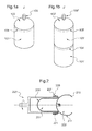
- the figure 1a shows a bladder in two pieces, that is to say a lower piece 101, which here forms the longest piece, and an upper piece 102, which here forms the shortest piece; and the figure 1b shows a three-piece bladder with, as before, a lower piece 101 'which is the longest piece and an upper piece 102' which forms the shortest piece, and an intermediate piece 103 'positioned between the lower piece 101 and the upper piece 102 'which here has substantially the same length as the lower piece 101'.
- the lower parts 101, 101 'and the upper parts 102, 102' comprise in practice at least a substantially hemispherical portion, or rounded, or cap-shaped.
- the upper portion 102, 102 ' generally comprises a mouth 106, 106' of connection to a gas tank (not shown).
- two consecutive pieces i.e., the lower piece 101 and the upper piece 102 in the example of the figure 1a and the lower piece 101 'and the intermediate piece 103' and the intermediate piece 103 'and the upper piece 102' in the example of the figure 1b
- a lap bonding zone 104, 104 ', 105' in a direction orthogonal to the longitudinal direction Z, Z 'of the bladder.
- a peripheral strip of an inner surface of one of the two parts to be assembled covers a peripheral strip of an outer surface of the other of the two parts to be assembled.
- the strips are glued to each other and thus form a lap bonding zone 104, 104 ', 105'.
- a strip is located near an edge of the part in question, or is contiguous to the edge.
- inside and outside designate the surfaces of the parts that are found either inside or outside the bladder once it has been made; the interior of the bladder being for example intended to contain a gas once the bladder in use.
- a section of the piece contiguous to the edge, comprising at least the band to be glued to be glued, is for example beveled or thinned.
- a traditional method consists, for example, in positioning a first piece 201 which comprises a strip 207 intended to be glued on its outer surface 208, for example the longest piece for convenience in a hollow metal mandrel 220, then to turn a portion 209 of the first piece 201 over a useful edge 221 of the mandrel 220 and to fold the portion 209 turned on itself, for example by forming a hem, so that the outer surface strip 208 to be glued is oriented outwards.
- a second piece 202 which then comprises a strip 210 intended to be glued on its inner surface 211, for example the shortest piece, is turned upside down, that is to say placed upside down, so that the strip 210 intended to be glued which is formed on the inner surface 211 is then found outside.
- the operator grasps the second piece 202 and the approach of the first piece 201 which is mounted on the mandrel 220. If necessary, the second piece 202 is for example inserted at least partly towards the inside of the mandrel 220, in the first piece 201. The strip 210 of the second piece 202 is then substantially parallel to the strip 207 of the first piece 201. Then the operator folds the strip 210 of the second piece 202 on that of the first piece 201, on top the useful edge 221 of the mandrel 220.
- the assembly operation along the band 207 of the first piece 201 is thus continued by turning the mandrel 220 as it goes.
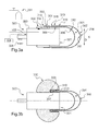
- the figures 3 and 4 illustrate examples of implementation of a method of assembling a bladder according to the invention, by means of elements designed for this purpose.
- an apparatus comprises at least one mandrel 320 provided with an inflatable device 330.
- the mandrel 320 is typically a rigid cylinder, straight, of longitudinal axis X and of diameter D.
- mandrel 320 is rotatable about its longitudinal axis X, i.e., it is configured to be rotated about its axis X.
- mandrel is possibly full, but it could be hollow (as is for example schematized figure 4 ), which would allow to introduce at least a portion of bladder part.
- the inflatable device 330 mounted on the mandrel 320, here has the shape of a torus. It is for example mounted as a ring around the mandrel 320, that is to say on an outer surface 323 of the mandrel 320. It is therefore annular and, to express that it has similar inflation properties all around the mandrel it is called an "annular axisymmetric inflation device".
- the annular axisymmetric inflatable device 330 is here connected to the mandrel by an attachment surface 332, which makes it possible to define an attachment line 333 on one side of the useful edge 321 of the mandrel.
- the annular axisymmetric inflatable device in a deflated state, is thus positioned behind the line of attachment 333 with respect to the useful edge 321.
- the annular axisymmetric inflatable device 330 is possibly glued to the surface 323 outer mandrel 320, by the attachment surface 332, to prevent it moves when inflated to return a strip of a part 301.
- the annular axisymmetric inflatable device 330 is also located at a constant distance from the useful edge 321 of the mandrel 320 to facilitate the realization of the steps of the assembly process of the parts to be assembled, especially if the two parts to be assembled are mounted on the same mandrel .
- the line of attachment 333 is parallel to the useful edge 321 (which is perpendicular to the axis of the mandrel).
- the annular axisymmetric inflatable device 330 is positioned near the useful edge 321, to a few centimeters, whereas, in the example of the figure 4 , the annular axisymmetric inflatable device is positioned substantially raz the useful edge 321 '.
- the apparatus comprises an inflation system 331 which is connected to the annular axisymmetric inflatable device 330 in a sealed manner.
- the inflation system 331 comprises, for example, a network of compressed air to which a hose is connected, itself connected to the annular axisymmetric inflatable device in a sealed manner.
- the inflation system 331 is possibly connected to the annular axisymmetric inflatable device 330 through the inside of the mandrel, through a hole formed in a wall of the mandrel, for example, under a location of the annular axisymmetric inflatable device 330 .
- the apparatus also possibly includes a laser, not shown here.
- the laser emits radiation that points at a predetermined distance from the useful edge 321 of the mandrel 320.
- the two parts 301, 302 to be assembled are mounted on the same mandrel 320, the part 301 being mounted upside down.
- the first piece 301 has an inner surface 312 and an outer surface 308, and on this inner surface near its edge 313, a peripheral strip 307 which is intended to be glued.
- the second piece 302 has an inner surface 311 and an outer surface 314, as well as, near an edge 315 on the outer surface 314, a peripheral band 310 which is to be glued.
- peripheral strips 307 and 310 are often bevelled, but the present description could equally well be applied to strips of constant thickness.
- the first part 301 is positioned on the mandrel 320 upside down, that is to say so that the strip 307, which is part of the inner surface of this part, is oriented towards the outside.
- the method comprises a step of threading the first piece 301 around the mandrel 320, with a portion 309 of the outer surface 308 of the first piece 301 facing the mandrel 320, that is to say, for example in facing relation, or in contact with, the surface 323 of the mandrel 320, and the inner surface strip 307 312 is oriented outwards.
- the peripheral strip 307 is positioned, at least in part and preferably completely, above the annular axisymmetric inflatable device 330, a few centimeters from the useful edge 321 so as to be able to position the peripheral strip of the second piece 302 at a later date. 307 to be returned is furthermore advantageously positioned beyond the line of attachment 333 of the inflatable device 330 to the mandrel 320.
- the second piece 302 is then placed here on the same mandrel 320, with its band 310 also facing outward. It is threaded, at the place, around the first piece 301, which is upside down. A section 316 of the second piece 302 thus also surrounds the mandrel 320. Thus, the inner surface 311 of the second piece 302 is in contact with, or in contact with at least a portion of, the inner surface 312 of the first piece 301.
- the strip 310 of outer surface 314 of the second piece 302 is preferably positioned in the vicinity of the strip 307 of the first piece 301, or even the strip 310 of the second piece 302 adjacent the strip 307 of the first piece 301, but the strip 310 of the second piece is preferably positioned just in front of the fastening edge 333 of the inflatable device 330.
- the strip 307 of the first piece 301 exceeds at least partially of the second room 302.
- the annular axisymmetric inflatable device 330 is inflated by means of the inflation system 331.
- the figure 3b illustrates the reversal of the strip 307 of the first piece 301 on the strip 310 of the second piece 302.
- the annular axisymmetric inflatable device 330 is gradually inflated.
- the annular axisymmetric inflatable device 330 is configured to expand beyond the attachment edge 333 when inflated. It is by exaggeration that it is shown that the annular axisymmetric inflatable device deforms to cover the edge 313; in practice, it suffices that this device is deformed to exceed, in its area covered by the edge 313, an orientation perpendicular to the axis of the mandrel.
- this material has a thickness which, on the side of the free edge of the mandrel (to the right to the figure 3b ) is less than the thickness of the opposite side (to the left).
- this reversal effect can be obtained by fixing the annular axisymmetric inflatable device in a staggered manner towards the edge useful, in relation to its central portion, in deflated configuration; thus it is understood that, if the device 330 is only fixed to the mandrel near its right edge, it will tend to move to the right as it inflates.
- the annular axisymmetric inflatable device here torus-shaped, with a single inflatable cavity, can be replaced by a succession of inflatable cavities extending around the mandrel.
- the apparatus finally comprises here a synchronization and control control system 324 which makes it possible to act on the inflation system 331 to adjust and control the deflation and inflation of the annular axisymmetric inflatable device 330 and, if necessary, to rotate the mandrel 320.
- the exemplary embodiment of the figure 4 differs in that the second piece 302 'is mounted on a mandrel different from that on which is mounted the first piece 301'.
- the apparatus therefore comprises a second mandrel 340 'on which is mounted the second part 302'.
- the mandrel 320 'on which is mounted the first part 301' is then called "first mandrel".
- the second mandrel 340 ' is similar to the first mandrel 320'. It has a useful edge 341 ', and is here rotatable. In addition, he is, here, hollow. It has for example a longitudinal axis Y 'and a diameter D "substantially equal to the diameter D' of the first mandrel 320 '.
- the second mandrel 340 ' is disposed with its longitudinal axis Y' aligned with the longitudinal axis X 'of the first mandrel 320', and with its working edge 341 'opposite the working edge 321' of the first mandrel 320 '.
- the apparatus may include a second laser (not shown) configured to control the positioning of a workpiece mounted thereon.
- the apparatus finally comprises a mechanism for bringing the first mandrel and the second mandrel closer together, not shown.
- the approximation mechanism comprises for example a rail on which are mounted the first mandrel 320 'and the second mandrel 340'.
- the approximation mechanism comprises a jack connected to at least one of the first mandrel 320 'or the second mandrel 340', for example attached to a fixing pin 317 ', 318' behind the mandrel 320 ', 340'.
- one of the two chucks is fixed while the other is movable (as schematized here), or both are movable.
- the first mandrel 320 ' is movable while the second mandrel 340' is fixed.
- the first part 301 ' is mounted upside down on the first mandrel 320' with its band 307 'on the annular axisymmetric inflatable device 330'.
- the annular axisymmetric inflatable device 330 ' is near the useful edge 321', or is contiguous to the useful edge 321 'so that the strip 307' is as close as possible to the strip 310 'of the second piece 302 'when turned around.
- the band 310 'of the second piece 302' is vis-à-vis the band 307 'of the first piece 301' during its turning, the second piece 302 'is inserted in part in the second mandrel 340' ; a section 316 'of the second part 302' which comprises at least the band 310 'is turned over the useful edge 341' of the second mandrel 340 ', and the band 310' is again turned over, thus forming a hem of the section 316 ', so as to be facing outwards.
- edge 315 'of the second piece 302' is directed towards the first piece 301 '.
- the first mandrel 320 'and the second mandrel 340' are brought closer together. the other. For example, they are brought together until they come into abutment against each other.
- the annular axisymmetric inflatable device is inflated and the band 307 'of the first piece 301' is returned to the band 310 'of the second piece 302'.
- the second mandrel 340 'could also comprise an annular axisymmetric inflatable device so that the first part can be indifferently mounted on one or other of the mandrels, the mandrel on which the first part is mounted then comprising the annular axisymmetric inflatable device to be inflated to perform the inversion of the band.
- the apparatus further comprises here a synchronization and control control system 324 'which makes it possible to act on the inflation system 331' to regulate and control the deflation and inflation of the annular axisymmetric inflatable device 330 'and, if necessary, to rotate and advance (if it is movable in translation) the first mandrel 320 '.
- a synchronization and control control system 324 ' which makes it possible to act on the inflation system 331' to regulate and control the deflation and inflation of the annular axisymmetric inflatable device 330 'and, if necessary, to rotate and advance (if it is movable in translation) the first mandrel 320 '.
- It also comprises an optional control and synchronization control system 324 which makes it possible to turn the second mandrel 340 '(or even to advance it if it was mobile, for example), or to manage an annular axisymmetric inflatable device if the second mandrel has one)
- the synchronization and control control system 324 'of the first mandrel 320' and the synchronization and control control system 324 "of the second mandrel 340 ' are grouped into a single control system.
- the strips 307, 307 'and 310, 310' are glued.
- the laser or lasers make it possible to verify their positioning, for example a distance from the edges 313, 313 ', 315, 315' of the first and second parts 301, 301 ', 302, 302' relative to the useful edge 321. , 321 ', 341' of the mandrels 320, 320 ', 340'. For example, to verify that the strip 307, 307 'of the first part 301, 301' is parallel to the strip 310, 310 ' of the second piece 302, 302 '. For this purpose, it is therefore very convenient that the mandrel or chucks are rotatable.
- marks and / or stops may also be present on the mandrels to facilitate the positioning of parts and strips to be glued.
- the first piece 301 corresponds to a top piece as illustrated on the figure 1 but it could of course be a lower part or an intermediate part.
Landscapes
- Engineering & Computer Science (AREA)
- Mechanical Engineering (AREA)
Priority Applications (1)
| Application Number | Priority Date | Filing Date | Title |
|---|---|---|---|
| PL15186280T PL3000585T3 (pl) | 2014-09-25 | 2015-09-22 | Sposób i urządzenie do złożenia części pęcherza |
Applications Claiming Priority (1)
| Application Number | Priority Date | Filing Date | Title |
|---|---|---|---|
| FR1459057A FR3026342B1 (fr) | 2014-09-25 | 2014-09-25 | Procede et appareil d'assemblage de pieces de vessie |
Publications (3)
| Publication Number | Publication Date |
|---|---|
| EP3000585A1 true EP3000585A1 (de) | 2016-03-30 |
| EP3000585B1 EP3000585B1 (de) | 2019-01-09 |
| EP3000585B8 EP3000585B8 (de) | 2019-03-27 |
Family
ID=51842650
Family Applications (1)
| Application Number | Title | Priority Date | Filing Date |
|---|---|---|---|
| EP15186280.2A Active EP3000585B8 (de) | 2014-09-25 | 2015-09-22 | Verfahren und gerät zum zusammenfügen von blasenteilen |
Country Status (3)
| Country | Link |
|---|---|
| EP (1) | EP3000585B8 (de) |
| FR (1) | FR3026342B1 (de) |
| PL (1) | PL3000585T3 (de) |
Citations (7)
| Publication number | Priority date | Publication date | Assignee | Title |
|---|---|---|---|---|
| US529142A (en) * | 1894-11-13 | Method of making bicycle-tires | ||
| US1557680A (en) * | 1922-08-17 | 1925-10-20 | Cupples Company Manufacturers | Cuffing machine |
| US1592809A (en) * | 1922-09-18 | 1926-07-13 | Firestone Tire & Rubber Co | Apparatus for forming cuffs on inner tubes |
| US1637465A (en) * | 1927-08-02 | bierman | ||
| US2698273A (en) * | 1949-10-19 | 1954-12-28 | Us Rubber Co | Method for joining thermoplastic sheet material |
| EP0803344A1 (de) | 1996-04-26 | 1997-10-29 | N.V. MEDIBEG S.A., naamloze vennootschap. | Verfahren zur Herstellung einer Membranblase für ein Ausdehnungsgefäss |
| JPH10156949A (ja) * | 1996-11-27 | 1998-06-16 | Nok Corp | 中空体の形成装置およびその形成方法 |
-
2014
- 2014-09-25 FR FR1459057A patent/FR3026342B1/fr active Active
-
2015
- 2015-09-22 EP EP15186280.2A patent/EP3000585B8/de active Active
- 2015-09-22 PL PL15186280T patent/PL3000585T3/pl unknown
Patent Citations (7)
| Publication number | Priority date | Publication date | Assignee | Title |
|---|---|---|---|---|
| US529142A (en) * | 1894-11-13 | Method of making bicycle-tires | ||
| US1637465A (en) * | 1927-08-02 | bierman | ||
| US1557680A (en) * | 1922-08-17 | 1925-10-20 | Cupples Company Manufacturers | Cuffing machine |
| US1592809A (en) * | 1922-09-18 | 1926-07-13 | Firestone Tire & Rubber Co | Apparatus for forming cuffs on inner tubes |
| US2698273A (en) * | 1949-10-19 | 1954-12-28 | Us Rubber Co | Method for joining thermoplastic sheet material |
| EP0803344A1 (de) | 1996-04-26 | 1997-10-29 | N.V. MEDIBEG S.A., naamloze vennootschap. | Verfahren zur Herstellung einer Membranblase für ein Ausdehnungsgefäss |
| JPH10156949A (ja) * | 1996-11-27 | 1998-06-16 | Nok Corp | 中空体の形成装置およびその形成方法 |
Also Published As
| Publication number | Publication date |
|---|---|
| EP3000585B1 (de) | 2019-01-09 |
| FR3026342A1 (fr) | 2016-04-01 |
| FR3026342B1 (fr) | 2017-04-28 |
| PL3000585T3 (pl) | 2019-06-28 |
| EP3000585B8 (de) | 2019-03-27 |
Similar Documents
| Publication | Publication Date | Title |
|---|---|---|
| EP3083407B1 (de) | Entfaltbarer aufblasbarer flügel | |
| EP3074176B1 (de) | Halterung zur pneumatischen blockierung einer optischen linse | |
| EP0171325B1 (de) | Hohler Tragkörper und Faserumwicklungsvorrichtung zur Herstellung des Hohlkörpers | |
| EP0176945B1 (de) | Vorvulkanisierte Lauffläche zur Runderneuerung von Reifen, Verfahren und Vorrichtung zur Herstellung derselben | |
| EP0020248A1 (de) | Vorrichtung für die Formgebung zylindrischer Artikel | |
| FR3086568A1 (fr) | Dispositif interieur de serrage et de soudage | |
| EP3000585B1 (de) | Verfahren und gerät zum zusammenfügen von blasenteilen | |
| CA2035109A1 (fr) | Armature de renfort articulee pour talon de renforcement de structure tubulaire souple et structure tubulaire souple comportant une telle armature de renfort | |
| EP1322461B1 (de) | Vorrichtung zum auflegen der lauffläche auf eine reifenkarkasse | |
| EP1163110B1 (de) | Verfahren zum auflegen der lauffläche auf eine reifenkarkasse | |
| FR2962314A1 (fr) | Dispositif d'aide et procede pour mettre un gant sur une main d'un utilisateur | |
| EP1345783A1 (de) | Reifen/dichtelement einheit und verfahren zur herstellung derselben | |
| EP0855268B1 (de) | Vorrichtung zum Fixieren von einer Druckhülse auf einem Druckwalzenkern | |
| EP0257455B1 (de) | Dichtungskörper für Rohrprüfpresse mittels Flüssigkeitsdruck | |
| EP0683046B1 (de) | Hülse zum Montieren auf Trägerzylindern von Flexodruckmaschinen | |
| FR2990376A1 (fr) | Procede de fabrication d'une peau en composite formant virole non demoulable | |
| EP3233456A1 (de) | Form und verfahren zum vulkanisieren eines ringförmigen adapters zur montage eines reifens auf einer felge | |
| FR2752286A1 (fr) | Dispositif pour le chemisage d'un branchement, procede de chemisage et gaine de chemisage | |
| EP2804746B1 (de) | Werkzeugbaugruppe und verfahren zur herstellung eines teils aus einem verbundwerkstoff | |
| FR3142933A1 (fr) | Outil pour le marouflage d’un pli de matiere tel qu’un preimpregne et procede de marouflage associe | |
| EP0987109B1 (de) | Automatische Dichtungsvorrichtung für Luftdurchgangslöchern in einem Zylinder, insbesondere für Trägerzylindern und Kompensationshülse | |
| WO2015118085A1 (fr) | Actionneur lineaire a structure souple et bras articule comportant un tel actionneur | |
| FR2960462A1 (fr) | Dispositif a verins utilisable lors du soudage d'une structure tubulaire, tel un mat d'eolienne | |
| EP4502440A1 (de) | Ventil und vorrichtung mit unter druck stehender flüssigkeit | |
| FR3151889A1 (fr) | Ensemble piston-diaphragme pour une vanne et procédé de fabrication |
Legal Events
| Date | Code | Title | Description |
|---|---|---|---|
| PUAI | Public reference made under article 153(3) epc to a published international application that has entered the european phase |
Free format text: ORIGINAL CODE: 0009012 |
|
| AK | Designated contracting states |
Kind code of ref document: A1 Designated state(s): AL AT BE BG CH CY CZ DE DK EE ES FI FR GB GR HR HU IE IS IT LI LT LU LV MC MK MT NL NO PL PT RO RS SE SI SK SM TR |
|
| AX | Request for extension of the european patent |
Extension state: BA ME |
|
| 17P | Request for examination filed |
Effective date: 20160607 |
|
| RBV | Designated contracting states (corrected) |
Designated state(s): AL AT BE BG CH CY CZ DE DK EE ES FI FR GB GR HR HU IE IS IT LI LT LU LV MC MK MT NL NO PL PT RO RS SE SI SK SM TR |
|
| RIC1 | Information provided on ipc code assigned before grant |
Ipc: B29C 65/78 20060101AFI20180716BHEP Ipc: B29C 67/00 20060101ALN20180716BHEP Ipc: F15B 1/10 20060101ALN20180716BHEP Ipc: B29C 53/02 20060101ALN20180716BHEP Ipc: B29C 57/00 20060101ALN20180716BHEP Ipc: B29C 65/48 20060101ALI20180716BHEP Ipc: B29D 22/02 20060101ALI20180716BHEP Ipc: B29L 22/02 20060101ALN20180716BHEP Ipc: B29K 21/00 20060101ALN20180716BHEP |
|
| GRAP | Despatch of communication of intention to grant a patent |
Free format text: ORIGINAL CODE: EPIDOSNIGR1 |
|
| STAA | Information on the status of an ep patent application or granted ep patent |
Free format text: STATUS: GRANT OF PATENT IS INTENDED |
|
| RIC1 | Information provided on ipc code assigned before grant |
Ipc: B29C 67/00 20060101ALN20180907BHEP Ipc: B29C 65/78 20060101AFI20180907BHEP Ipc: B29D 22/02 20060101ALI20180907BHEP Ipc: B29C 57/00 20060101ALN20180907BHEP Ipc: B29C 53/02 20060101ALN20180907BHEP Ipc: B29K 21/00 20060101ALN20180907BHEP Ipc: B29C 65/48 20060101ALI20180907BHEP Ipc: B29L 22/02 20060101ALN20180907BHEP Ipc: F15B 1/10 20060101ALN20180907BHEP |
|
| INTG | Intention to grant announced |
Effective date: 20180926 |
|
| GRAS | Grant fee paid |
Free format text: ORIGINAL CODE: EPIDOSNIGR3 |
|
| GRAA | (expected) grant |
Free format text: ORIGINAL CODE: 0009210 |
|
| STAA | Information on the status of an ep patent application or granted ep patent |
Free format text: STATUS: THE PATENT HAS BEEN GRANTED |
|
| AK | Designated contracting states |
Kind code of ref document: B1 Designated state(s): AL AT BE BG CH CY CZ DE DK EE ES FI FR GB GR HR HU IE IS IT LI LT LU LV MC MK MT NL NO PL PT RO RS SE SI SK SM TR |
|
| REG | Reference to a national code |
Ref country code: GB Ref legal event code: FG4D Free format text: NOT ENGLISH |
|
| REG | Reference to a national code |
Ref country code: CH Ref legal event code: EP Ref country code: AT Ref legal event code: REF Ref document number: 1086765 Country of ref document: AT Kind code of ref document: T Effective date: 20190115 |
|
| GRAT | Correction requested after decision to grant or after decision to maintain patent in amended form |
Free format text: ORIGINAL CODE: EPIDOSNCDEC |
|
| REG | Reference to a national code |
Ref country code: IE Ref legal event code: FG4D Free format text: LANGUAGE OF EP DOCUMENT: FRENCH |
|
| REG | Reference to a national code |
Ref country code: DE Ref legal event code: R096 Ref document number: 602015023089 Country of ref document: DE |
|
| REG | Reference to a national code |
Ref country code: DE Ref legal event code: R081 Ref document number: 602015023089 Country of ref document: DE Owner name: SOCIETE AUXILIAIRE DE FABRICATION DE LA SACATE, FR Free format text: FORMER OWNER: SOCIETE AUXILIARE DE FABRICATION DE LA SACATEC, YDES, FR |
|
| REG | Reference to a national code |
Ref country code: CH Ref legal event code: PK Free format text: RECTIFICATION B8 |
|
| RAP2 | Party data changed (patent owner data changed or rights of a patent transferred) |
Owner name: SOCIETE AUXILIAIRE DE FABRICATION DE LA SACATEC |
|
| REG | Reference to a national code |
Ref country code: NL Ref legal event code: MP Effective date: 20190109 |
|
| REG | Reference to a national code |
Ref country code: LT Ref legal event code: MG4D |
|
| PG25 | Lapsed in a contracting state [announced via postgrant information from national office to epo] |
Ref country code: NL Free format text: LAPSE BECAUSE OF FAILURE TO SUBMIT A TRANSLATION OF THE DESCRIPTION OR TO PAY THE FEE WITHIN THE PRESCRIBED TIME-LIMIT Effective date: 20190109 |
|
| REG | Reference to a national code |
Ref country code: AT Ref legal event code: MK05 Ref document number: 1086765 Country of ref document: AT Kind code of ref document: T Effective date: 20190109 |
|
| PG25 | Lapsed in a contracting state [announced via postgrant information from national office to epo] |
Ref country code: ES Free format text: LAPSE BECAUSE OF FAILURE TO SUBMIT A TRANSLATION OF THE DESCRIPTION OR TO PAY THE FEE WITHIN THE PRESCRIBED TIME-LIMIT Effective date: 20190109 Ref country code: LT Free format text: LAPSE BECAUSE OF FAILURE TO SUBMIT A TRANSLATION OF THE DESCRIPTION OR TO PAY THE FEE WITHIN THE PRESCRIBED TIME-LIMIT Effective date: 20190109 Ref country code: NO Free format text: LAPSE BECAUSE OF FAILURE TO SUBMIT A TRANSLATION OF THE DESCRIPTION OR TO PAY THE FEE WITHIN THE PRESCRIBED TIME-LIMIT Effective date: 20190409 Ref country code: PT Free format text: LAPSE BECAUSE OF FAILURE TO SUBMIT A TRANSLATION OF THE DESCRIPTION OR TO PAY THE FEE WITHIN THE PRESCRIBED TIME-LIMIT Effective date: 20190509 Ref country code: SE Free format text: LAPSE BECAUSE OF FAILURE TO SUBMIT A TRANSLATION OF THE DESCRIPTION OR TO PAY THE FEE WITHIN THE PRESCRIBED TIME-LIMIT Effective date: 20190109 Ref country code: FI Free format text: LAPSE BECAUSE OF FAILURE TO SUBMIT A TRANSLATION OF THE DESCRIPTION OR TO PAY THE FEE WITHIN THE PRESCRIBED TIME-LIMIT Effective date: 20190109 |
|
| PG25 | Lapsed in a contracting state [announced via postgrant information from national office to epo] |
Ref country code: HR Free format text: LAPSE BECAUSE OF FAILURE TO SUBMIT A TRANSLATION OF THE DESCRIPTION OR TO PAY THE FEE WITHIN THE PRESCRIBED TIME-LIMIT Effective date: 20190109 Ref country code: LV Free format text: LAPSE BECAUSE OF FAILURE TO SUBMIT A TRANSLATION OF THE DESCRIPTION OR TO PAY THE FEE WITHIN THE PRESCRIBED TIME-LIMIT Effective date: 20190109 Ref country code: IS Free format text: LAPSE BECAUSE OF FAILURE TO SUBMIT A TRANSLATION OF THE DESCRIPTION OR TO PAY THE FEE WITHIN THE PRESCRIBED TIME-LIMIT Effective date: 20190509 Ref country code: RS Free format text: LAPSE BECAUSE OF FAILURE TO SUBMIT A TRANSLATION OF THE DESCRIPTION OR TO PAY THE FEE WITHIN THE PRESCRIBED TIME-LIMIT Effective date: 20190109 Ref country code: BG Free format text: LAPSE BECAUSE OF FAILURE TO SUBMIT A TRANSLATION OF THE DESCRIPTION OR TO PAY THE FEE WITHIN THE PRESCRIBED TIME-LIMIT Effective date: 20190409 Ref country code: GR Free format text: LAPSE BECAUSE OF FAILURE TO SUBMIT A TRANSLATION OF THE DESCRIPTION OR TO PAY THE FEE WITHIN THE PRESCRIBED TIME-LIMIT Effective date: 20190410 |
|
| REG | Reference to a national code |
Ref country code: DE Ref legal event code: R097 Ref document number: 602015023089 Country of ref document: DE |
|
| PG25 | Lapsed in a contracting state [announced via postgrant information from national office to epo] |
Ref country code: SK Free format text: LAPSE BECAUSE OF FAILURE TO SUBMIT A TRANSLATION OF THE DESCRIPTION OR TO PAY THE FEE WITHIN THE PRESCRIBED TIME-LIMIT Effective date: 20190109 Ref country code: AL Free format text: LAPSE BECAUSE OF FAILURE TO SUBMIT A TRANSLATION OF THE DESCRIPTION OR TO PAY THE FEE WITHIN THE PRESCRIBED TIME-LIMIT Effective date: 20190109 Ref country code: CZ Free format text: LAPSE BECAUSE OF FAILURE TO SUBMIT A TRANSLATION OF THE DESCRIPTION OR TO PAY THE FEE WITHIN THE PRESCRIBED TIME-LIMIT Effective date: 20190109 Ref country code: DK Free format text: LAPSE BECAUSE OF FAILURE TO SUBMIT A TRANSLATION OF THE DESCRIPTION OR TO PAY THE FEE WITHIN THE PRESCRIBED TIME-LIMIT Effective date: 20190109 Ref country code: RO Free format text: LAPSE BECAUSE OF FAILURE TO SUBMIT A TRANSLATION OF THE DESCRIPTION OR TO PAY THE FEE WITHIN THE PRESCRIBED TIME-LIMIT Effective date: 20190109 Ref country code: EE Free format text: LAPSE BECAUSE OF FAILURE TO SUBMIT A TRANSLATION OF THE DESCRIPTION OR TO PAY THE FEE WITHIN THE PRESCRIBED TIME-LIMIT Effective date: 20190109 Ref country code: AT Free format text: LAPSE BECAUSE OF FAILURE TO SUBMIT A TRANSLATION OF THE DESCRIPTION OR TO PAY THE FEE WITHIN THE PRESCRIBED TIME-LIMIT Effective date: 20190109 |
|
| PLBE | No opposition filed within time limit |
Free format text: ORIGINAL CODE: 0009261 |
|
| STAA | Information on the status of an ep patent application or granted ep patent |
Free format text: STATUS: NO OPPOSITION FILED WITHIN TIME LIMIT |
|
| PG25 | Lapsed in a contracting state [announced via postgrant information from national office to epo] |
Ref country code: SM Free format text: LAPSE BECAUSE OF FAILURE TO SUBMIT A TRANSLATION OF THE DESCRIPTION OR TO PAY THE FEE WITHIN THE PRESCRIBED TIME-LIMIT Effective date: 20190109 |
|
| 26N | No opposition filed |
Effective date: 20191010 |
|
| PG25 | Lapsed in a contracting state [announced via postgrant information from national office to epo] |
Ref country code: SI Free format text: LAPSE BECAUSE OF FAILURE TO SUBMIT A TRANSLATION OF THE DESCRIPTION OR TO PAY THE FEE WITHIN THE PRESCRIBED TIME-LIMIT Effective date: 20190109 |
|
| PG25 | Lapsed in a contracting state [announced via postgrant information from national office to epo] |
Ref country code: TR Free format text: LAPSE BECAUSE OF FAILURE TO SUBMIT A TRANSLATION OF THE DESCRIPTION OR TO PAY THE FEE WITHIN THE PRESCRIBED TIME-LIMIT Effective date: 20190109 |
|
| PG25 | Lapsed in a contracting state [announced via postgrant information from national office to epo] |
Ref country code: MC Free format text: LAPSE BECAUSE OF FAILURE TO SUBMIT A TRANSLATION OF THE DESCRIPTION OR TO PAY THE FEE WITHIN THE PRESCRIBED TIME-LIMIT Effective date: 20190109 |
|
| REG | Reference to a national code |
Ref country code: CH Ref legal event code: PL |
|
| PG25 | Lapsed in a contracting state [announced via postgrant information from national office to epo] |
Ref country code: IE Free format text: LAPSE BECAUSE OF NON-PAYMENT OF DUE FEES Effective date: 20190922 Ref country code: LU Free format text: LAPSE BECAUSE OF NON-PAYMENT OF DUE FEES Effective date: 20190922 Ref country code: CH Free format text: LAPSE BECAUSE OF NON-PAYMENT OF DUE FEES Effective date: 20190930 Ref country code: LI Free format text: LAPSE BECAUSE OF NON-PAYMENT OF DUE FEES Effective date: 20190930 |
|
| REG | Reference to a national code |
Ref country code: BE Ref legal event code: MM Effective date: 20190930 |
|
| PG25 | Lapsed in a contracting state [announced via postgrant information from national office to epo] |
Ref country code: BE Free format text: LAPSE BECAUSE OF NON-PAYMENT OF DUE FEES Effective date: 20190930 |
|
| PG25 | Lapsed in a contracting state [announced via postgrant information from national office to epo] |
Ref country code: CY Free format text: LAPSE BECAUSE OF FAILURE TO SUBMIT A TRANSLATION OF THE DESCRIPTION OR TO PAY THE FEE WITHIN THE PRESCRIBED TIME-LIMIT Effective date: 20190109 |
|
| PG25 | Lapsed in a contracting state [announced via postgrant information from national office to epo] |
Ref country code: HU Free format text: LAPSE BECAUSE OF FAILURE TO SUBMIT A TRANSLATION OF THE DESCRIPTION OR TO PAY THE FEE WITHIN THE PRESCRIBED TIME-LIMIT; INVALID AB INITIO Effective date: 20150922 Ref country code: MT Free format text: LAPSE BECAUSE OF FAILURE TO SUBMIT A TRANSLATION OF THE DESCRIPTION OR TO PAY THE FEE WITHIN THE PRESCRIBED TIME-LIMIT Effective date: 20190109 |
|
| PG25 | Lapsed in a contracting state [announced via postgrant information from national office to epo] |
Ref country code: MK Free format text: LAPSE BECAUSE OF FAILURE TO SUBMIT A TRANSLATION OF THE DESCRIPTION OR TO PAY THE FEE WITHIN THE PRESCRIBED TIME-LIMIT Effective date: 20190109 |
|
| PGFP | Annual fee paid to national office [announced via postgrant information from national office to epo] |
Ref country code: IT Payment date: 20240926 Year of fee payment: 10 |
|
| PGFP | Annual fee paid to national office [announced via postgrant information from national office to epo] |
Ref country code: DE Payment date: 20250926 Year of fee payment: 11 |
|
| PGFP | Annual fee paid to national office [announced via postgrant information from national office to epo] |
Ref country code: PL Payment date: 20250826 Year of fee payment: 11 |
|
| PGFP | Annual fee paid to national office [announced via postgrant information from national office to epo] |
Ref country code: GB Payment date: 20250826 Year of fee payment: 11 |
|
| PGFP | Annual fee paid to national office [announced via postgrant information from national office to epo] |
Ref country code: FR Payment date: 20250925 Year of fee payment: 11 |