EP3000540A1 - Offset correction control device and offset correction control method for continuous tack welding device - Google Patents
Offset correction control device and offset correction control method for continuous tack welding device Download PDFInfo
- Publication number
- EP3000540A1 EP3000540A1 EP13885172.0A EP13885172A EP3000540A1 EP 3000540 A1 EP3000540 A1 EP 3000540A1 EP 13885172 A EP13885172 A EP 13885172A EP 3000540 A1 EP3000540 A1 EP 3000540A1
- Authority
- EP
- European Patent Office
- Prior art keywords
- offset correction
- steel plate
- offset
- offset amount
- cage rolls
- Prior art date
- Legal status (The legal status is an assumption and is not a legal conclusion. Google has not performed a legal analysis and makes no representation as to the accuracy of the status listed.)
- Granted
Links
Images


Classifications
-
- B—PERFORMING OPERATIONS; TRANSPORTING
- B23—MACHINE TOOLS; METAL-WORKING NOT OTHERWISE PROVIDED FOR
- B23K—SOLDERING OR UNSOLDERING; WELDING; CLADDING OR PLATING BY SOLDERING OR WELDING; CUTTING BY APPLYING HEAT LOCALLY, e.g. FLAME CUTTING; WORKING BY LASER BEAM
- B23K37/00—Auxiliary devices or processes, not specially adapted for a procedure covered by only one of the other main groups of this subclass
- B23K37/04—Auxiliary devices or processes, not specially adapted for a procedure covered by only one of the other main groups of this subclass for holding or positioning work
- B23K37/053—Auxiliary devices or processes, not specially adapted for a procedure covered by only one of the other main groups of this subclass for holding or positioning work aligning cylindrical work; Clamping devices therefor
- B23K37/0535—Longitudinal pipe seam alignment clamps
-
- B—PERFORMING OPERATIONS; TRANSPORTING
- B23—MACHINE TOOLS; METAL-WORKING NOT OTHERWISE PROVIDED FOR
- B23K—SOLDERING OR UNSOLDERING; WELDING; CLADDING OR PLATING BY SOLDERING OR WELDING; CUTTING BY APPLYING HEAT LOCALLY, e.g. FLAME CUTTING; WORKING BY LASER BEAM
- B23K26/00—Working by laser beam, e.g. welding, cutting or boring
- B23K26/02—Positioning or observing the workpiece, e.g. with respect to the point of impact; Aligning, aiming or focusing the laser beam
- B23K26/04—Automatically aligning, aiming or focusing the laser beam, e.g. using the back-scattered light
- B23K26/044—Seam tracking
-
- B—PERFORMING OPERATIONS; TRANSPORTING
- B23—MACHINE TOOLS; METAL-WORKING NOT OTHERWISE PROVIDED FOR
- B23K—SOLDERING OR UNSOLDERING; WELDING; CLADDING OR PLATING BY SOLDERING OR WELDING; CUTTING BY APPLYING HEAT LOCALLY, e.g. FLAME CUTTING; WORKING BY LASER BEAM
- B23K26/00—Working by laser beam, e.g. welding, cutting or boring
- B23K26/20—Bonding
- B23K26/21—Bonding by welding
- B23K26/24—Seam welding
- B23K26/26—Seam welding of rectilinear seams
- B23K26/262—Seam welding of rectilinear seams of longitudinal seams of tubes
-
- B—PERFORMING OPERATIONS; TRANSPORTING
- B23—MACHINE TOOLS; METAL-WORKING NOT OTHERWISE PROVIDED FOR
- B23K—SOLDERING OR UNSOLDERING; WELDING; CLADDING OR PLATING BY SOLDERING OR WELDING; CUTTING BY APPLYING HEAT LOCALLY, e.g. FLAME CUTTING; WORKING BY LASER BEAM
- B23K9/00—Arc welding or cutting
- B23K9/02—Seam welding; Backing means; Inserts
- B23K9/025—Seam welding; Backing means; Inserts for rectilinear seams
- B23K9/0253—Seam welding; Backing means; Inserts for rectilinear seams for the longitudinal seam of tubes
-
- B—PERFORMING OPERATIONS; TRANSPORTING
- B21—MECHANICAL METAL-WORKING WITHOUT ESSENTIALLY REMOVING MATERIAL; PUNCHING METAL
- B21C—MANUFACTURE OF METAL SHEETS, WIRE, RODS, TUBES, PROFILES OR LIKE SEMI-MANUFACTURED PRODUCTS OTHERWISE THAN BY ROLLING; AUXILIARY OPERATIONS USED IN CONNECTION WITH METAL-WORKING WITHOUT ESSENTIALLY REMOVING MATERIAL
- B21C37/00—Manufacture of metal sheets, rods, wire, tubes, profiles or like semi-manufactured products, not otherwise provided for; Manufacture of tubes of special shape
- B21C37/06—Manufacture of metal sheets, rods, wire, tubes, profiles or like semi-manufactured products, not otherwise provided for; Manufacture of tubes of special shape of tubes or metal hoses; Combined procedures for making tubes, e.g. for making multi-wall tubes
- B21C37/08—Making tubes with welded or soldered seams
-
- B—PERFORMING OPERATIONS; TRANSPORTING
- B23—MACHINE TOOLS; METAL-WORKING NOT OTHERWISE PROVIDED FOR
- B23K—SOLDERING OR UNSOLDERING; WELDING; CLADDING OR PLATING BY SOLDERING OR WELDING; CUTTING BY APPLYING HEAT LOCALLY, e.g. FLAME CUTTING; WORKING BY LASER BEAM
- B23K37/00—Auxiliary devices or processes, not specially adapted for a procedure covered by only one of the other main groups of this subclass
- B23K37/04—Auxiliary devices or processes, not specially adapted for a procedure covered by only one of the other main groups of this subclass for holding or positioning work
Definitions
- the present invention relates to an offset correction controller and an offset correction control method in a continuous tack welding machine that constrains a cylindrical steel plate from an outer periphery side using a plurality of cage rolls, butts edges in a width direction of the steel plate, and performs continuous tack welding.
- a manufacturing process of a UOE steel pipe includes: a process in which edges in the width direction of a thick steel plate serving as a raw material are subjected to edge milling, a forming process in which the edges in the width direction of the thick steel plate are subjected to edge bending using a C-press machine and thereafter the thick steel plate is formed in a cylindrical shape in such a manner that the edges in the width direction of the thick steel plate face each other using a U-press machine and an O-press machine, a tack welding process in which the edges facing each other in the width direction are butted and the butted portion is tack welded while the cylindrical thick steel plate is constrained, a permanent welding process in which inner and outer surfaces of the butted portion of the thick steel plate are seam welded by a submerged arc welding method, and a pipe expanding process in which the steel pipe is expanded from the inside thereof using a pipe expander to form the steel pipe having a certain roundness, straightness, and outer diameter.
- the tack welding process in the manufacturing process of the UOE steel pipe uses a continuous tack welding machine that continuously performs tack welding on the cylindrical thick steel plate while conveying the thick steel plate and constraining the thick steel plate by the multiple cage rolls before the conveyance to the welding machine.
- the continuous tack welding machine is required to perform the tack welding such that the butted portion of the thick steel plate does not produce a level difference (hereinafter, described as an offset) of more than a permissible amount in the butted portion of the thick steel plate taking into consideration influence on a dimensional specification of the steel pipe and quality of the permanent welding process.
- an offset level difference
- Patent Literature 1 a technique is proposed that detects an offset amount of a butted portion and controls constraining forces of a plurality of cage rolls such that the offset amount becomes smaller than a permissible amount.
- Patent Literature 1 Japanese Patent Application Laid-open No. H05-211
- the constraining force required to constrain the cylindrical thick steel plate by the multiple cage rolls changes depending on the outer diameter and the thickness of the thick steel plate.
- the technique described in Patent Literature 1 controls the straining forces of the multiple cage rolls without taking into consideration the outer diameter and the thickness of the thick steel plate.
- the technique described in Patent Literature 1 thus causes the constraining forces of the multiple cage rolls to be excessively larger than the constraining force appropriate for the outer diameter and the thickness of the thick steel plate, resulting in a friction force between the edges in the width direction being increased, thereby making it impossible to correct the offset in some cases.
- techniques have been expected that can correct the offset of the butted portion taking into consideration the outer diameter and the thickness of the thick steel plate.
- the present invention is made and aims to provide an offset correction controller and an offset correction control method that can correct the offset of the butted area taking into consideration the outer diameter and the thickness of a steel plate, in a continuous tack welding machine.
- An offset correction controller in a continuous tack welding machine of the present invention constrains a cylindrical steel plate from an outer periphery side using a plurality of cage rolls, butts edges in a width direction of the steel plate, performs continuous tack welding and includes: a detection unit that detects an offset amount between the edges in the width direction at a butted portion of the steel plate; and an offset correction control unit that adjusts constraining forces of the cage rolls arranged on both sides of the butted portion such that the offset amount becomes smaller than a certain value when the offset amount detected by the detection unit is equal to or larger than the certain value, and reduces the constraining forces of other cage rolls when the offset amount does not become smaller than the certain value after the adjustment of the constraining forces of the cage rolls arranged on both sides of the butted portion.
- the offset correction controller in the continuous tack welding machine includes a table indicating a relation between an outer diameter and a thickness of the steel plate and upper limit values of the constraining forces of the cage rolls; reads, from the table, the upper limit values of the constraining forces of the cage rolls corresponding to the outer diameter and the thickness of the steel plate to be processed; and reduces the constraining forces of other cage rolls to the read upper limit values.
- the offset correction controller in the continuous tack welding machine adjusts the constraining forces of the cage rolls arranged on both sides of the butted portion such that the offset amount becomes smaller than the certain value when the offset amount detected by the detection unit continues to be equal to or larger than a certain value for a certain period of time or longer.
- An offset correction control method in a continuous tack welding machine constrains a cylindrical steel plate from an outer periphery side using a plurality of cage rolls, butts edges in a width direction of the steel plate, and performs continuous tack welding.
- the offset correction control method includes: detecting an offset amount between the edges in the width direction at a butted portion of the steel plate; and adjusting constraining forces of the cage rolls arranged on both sides of the butted portion such that the offset amount becomes smaller than a certain value when the offset amount detected at the detecting is equal to or larger than the certain value, and reducing the constraining forces of other cage rolls when the offset amount does not become smaller than the certain value after the adjusting of the constraining forces of the cage rolls arranged on both sides of the butted portion.
- the offset correction controller and the offset correction control method in the continuous tack welding machine according to the present invention can correct the offset of the butted portion taking into consideration the outer diameter and the thickness of the steel plate.
- FIG. 1 is a schematic diagram illustrating the continuous tack welding machine to which the offset correction controller according to the embodiment of the present invention is applied.
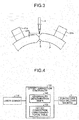
- FIG. 2 is a schematic diagram illustrating a structure of a constraining device illustrated in FIG. 1 .
- a continuous tack welding machine 1 to which the offset correction controller in the embodiment of the present invention is applied, includes a conveyer 2, a constraining device 3, and a tack welding torch 4 as major components.
- the conveyer 2 includes a chain (dock chain) 23 that has a claw 22 and is stretched between a plurality of rolls 21 arranged in a conveying direction of a steel pipe P.
- the conveyer 2 conveys the steel pipe P in the conveying direction by rotating the chain 23 while catching the rear end lower portion of the steel pipe P with the claw 22.
- the constraining device 3 constrains the steel pipe P from the outer peripheral side when a butted portion S of the steel pipe is tack welded.
- the constraining device 3 includes 8 cage rolls 31a to 31h circumferentially arranged such that the cage rolls constrain the steel pipe P from the outer peripheral side and a seam guiding roll 32 that forcibly guides the butted portion S of the steel pipe from straight above.
- the cage rolls 31a to 31h and the seam guiding rolls 32 are arranged in line along the longitudinal direction of the steel pipe P.
- the cage rolls 31a to 31h and the seam guiding rolls 32 are provided with hydraulic cylinders 33 each individually adjusting the corresponding press down stroke in the corresponding radial direction of the steel pipe P.
- the respective constraining forces of the steel pipe P can be automatically controlled by adjusting the respective press down strokes in the radial directions of the steel pipe P of the cage rolls 31a to 31h and the seam guiding rolls 32 using the respective hydraulic cylinders 33.
- the tack welding torch 4 includes an arc welder or a laser beam welder.
- the tack welding torch 4 tack welds the butted portion S of the steel pipe P constrained by the constraining device 3.
- the continuous tack welding machine 1 thus structured is required to perform the tack welding such that an offset amount ⁇ H (refer to FIG. 3 ) of the butted portion S of the steel pipe P becomes smaller than a permissible amount taking into consideration influence on a dimensional specification of the steel pipe P and quality of the permanent welding process, for example.
- the offset correction controller in the embodiment of the present invention controls the tack welding process in such a manner as described below. The following describes a structure and operation of the offset correction controller in the embodiment of the present invention with reference to FIGS. 4 to 7 .
- FIG. 4 is a block diagram illustrating the structure of the offset correction controller in the embodiment of the present invention.
- FIG. 5 is a schematic diagram illustrating an arrangement position of a laser sensor illustrated in FIG. 4 .
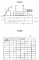
- FIG. 6 is a schematic diagram illustrating an offset correction constraining force table illustrated in FIG. 4 .
- an offset correction controller 100 in the embodiment of the present invention is achieved by an information processing apparatus such as a personal computer, and is electrically connected to a laser sensor 110 and the continuous tack welding machine 1 illustrated in FIG. 1 .
- the laser sensor 110 is disposed between the seam guiding rolls 32 and the tack welding torch 4 and continuously detects the offset amount ⁇ H of the butted portion S.
- the laser sensor 110 inputs an electrical signal indicating the detected offset amount ⁇ H to the offset correction controller 100. It is preferable that an optical filter and a douser be disposed around the laser sensor 110 in order to prevent influence of ambient light due to the tack welding during the detection of the offset amount ⁇ H.
- the offset correction controller 100 includes an abnormality determination timer 101 and an offset correction constraining force table 102.
- the abnormality determination timer 101 measures a period of time in which the offset amount ⁇ H is equal to or larger than an abnormality determination value (e.g., 1.0 mm).
- the abnormality determination timer 101 starts measuring time at a timing when the offset amount ⁇ H is equal to or larger than the abnormality determination value and ends the measurement of time at a timing when the offset amount ⁇ H becomes smaller than the abnormality determination value. As illustrated in FIG.
- the offset correction constraining force table 102 indicates setting values ( ⁇ initial values) of constraining forces of the cage rollers 31b, 31c, 31f, and 31g applied on the steel pipe P, which forces are specified for each outer diameter and thickness of the steel pipe P, used in a case where the offset amount ⁇ H of the butted portion S of the steel pipe P does not become smaller than the abnormality determination value.
- FIG. 7 is a flowchart illustrating the procedure of the offset correction control processing in the embodiment of the present invention.
- the processing starts at a timing when an instruction to perform tack welding is input and the offset correction control processing proceeds to the processing at step S1.
- the offset correction control processing is repeated at a certain control period while the tack welding is performed.
- the offset correction controller 100 detects the offset amount ⁇ H of the butted portion S through the laser sensor 110.
- the processing at step S1 is completed, and the offset correction control processing proceeds to the processing at step S2.
- the offset correction controller 100 determines whether the offset amount ⁇ H continues to exceed the abnormality determination value for a certain period of time (e.g., 0.5 seconds) or longer on the basis of the time measured by the abnormality determination timer 101. If the offset amount ⁇ H does not continue to exceed the abnormality determination value for the certain period of time or longer as the determination result, the offset correction controller 100 ends the offset correction control processing. If the offset amount ⁇ H continues to exceed the abnormality determination value for the certain period of time or longer, the offset correction control processing of the offset correction controller 100 proceeds to the processing at step S3.
- a certain period of time e.g., 0.5 seconds
- the offset correction controller 100 may control the continuous tack welding machine 1 such that the continuous tack welding machine 1 stops the tack welding.
- an abnormality upper limit determination value e.g., 1.8 mm
- the offset correction controller 100 adjusts the constraining forces of the cage rolls 31a and 31h, which are arranged such that the butted portion S is interposed therebetween, relatively to each other such that the offset amount ⁇ H detected by the processing at step S1 becomes smaller than the abnormality determination value.
- the processing at step S3 is completed, and the offset correction control processing proceeds to the processing at step S4.
- the offset correction controller 100 detects the offset amount ⁇ H after the processing at step S3 through the laser sensor 110 and determines whether the offset amount ⁇ H is smaller than the abnormality determination value. If the offset amount ⁇ H is not smaller than the abnormality determination value as the result of the determination, the offset correction controller 100 determines that the straining forces of the cage rolls 31b, 31c, 31f, and 31g are excessively large and then the offset correction control processing of the offset correction controller 100 proceeds to the processing at step S5. If the offset amount ⁇ H is smaller than the abnormality determination value, the offset correction control processing of the offset correction controller 100 proceeds to the processing at step S6.
- the offset correction controller 100 reads, from the offset correction constraining force table 102, the setting values of the constraining forces that correspond to the outer diameter and the thickness of the steel pipe P and are to be used in a case where the offset amount ⁇ H of the butted portion S does not become smaller than the abnormality determination value, and reduces the constraining forces of the cage rolls 31b, 31c, 31f, and 31g to the read setting values from the initial values.
- the processing at step S5 is completed, and the offset correction control processing returns to the processing at step S3.
- the offset correction controller 100 controls the continuous tack welding machine 1 such that the continuous tack welding machine 1 welds the butted portion S of the steel pipe P.
- the processing at step S6 is completed, and thus the series of steps of the offset correction control processing end.
- the offset correction controller 100 adjusts the constraining forces of the cage rolls 31a and 31h, which are arranged such that the butted portion S is interposed therebetween, such that the offset amount ⁇ H becomes smaller than the abnormality determination value.
- the offset correction controller 100 reduces the constraining forces of the cage rolls 31b, 31c, 31f, and 31g. As a result, the offset amount ⁇ H of the butted portion S can be corrected taking into consideration the outer diameter and the thickness of the steel plate.
- the constraining forces of the cage rolls 31b, 31c, 31f, and 31g are automatically adjusted when the offset amount ⁇ H of the butted portion S continues to exceed the abnormality determination value for the certain period of time or longer.
- welding operation is temporarily stopped, the constraining forces of the cage rolls 31b, 31c, 31f, and 31g are adjusted, and thereafter the welding operation is restarted in a case where it is difficult to automatically adjust the constraining forces of the cage rolls 31b, 31c, 31f, and 31g, when the constraining forces of the cage rolls 31b, 31c, 31f, and 31g are adjusted using relief valves (which are open when pressure of a certain value or more is applied to keep the certain pressure), for example.
- relief valves which are open when pressure of a certain value or more is applied to keep the certain pressure
- the technique of the present invention can be applied to the tack welding process when a bending press method is used instead of the method in which the U forming and the O forming are performed using the U-press machine and the O-press machine in the forming process in which the thick steel plate is formed in a cylindrical shape such that the edges in the width direction of the thick steel plate face each other.
- the thick steel plate is placed on two dies that have a straight line shape and are arranged in parallel with each other with a certain space left therebetween, and a portion above the space of the thick steel plate is pressed down by a punch.
- the present invention can correct the offset of the butted portion taking into consideration the outer diameter and the thickness of the steel plate.
Landscapes
- Physics & Mathematics (AREA)
- Engineering & Computer Science (AREA)
- Optics & Photonics (AREA)
- Mechanical Engineering (AREA)
- Plasma & Fusion (AREA)
- Arc Welding In General (AREA)
- Butt Welding And Welding Of Specific Article (AREA)
Abstract
Description
- The present invention relates to an offset correction controller and an offset correction control method in a continuous tack welding machine that constrains a cylindrical steel plate from an outer periphery side using a plurality of cage rolls, butts edges in a width direction of the steel plate, and performs continuous tack welding.
- Generally, a manufacturing process of a UOE steel pipe includes: a process in which edges in the width direction of a thick steel plate serving as a raw material are subjected to edge milling, a forming process in which the edges in the width direction of the thick steel plate are subjected to edge bending using a C-press machine and thereafter the thick steel plate is formed in a cylindrical shape in such a manner that the edges in the width direction of the thick steel plate face each other using a U-press machine and an O-press machine, a tack welding process in which the edges facing each other in the width direction are butted and the butted portion is tack welded while the cylindrical thick steel plate is constrained, a permanent welding process in which inner and outer surfaces of the butted portion of the thick steel plate are seam welded by a submerged arc welding method, and a pipe expanding process in which the steel pipe is expanded from the inside thereof using a pipe expander to form the steel pipe having a certain roundness, straightness, and outer diameter.
- The tack welding process in the manufacturing process of the UOE steel pipe uses a continuous tack welding machine that continuously performs tack welding on the cylindrical thick steel plate while conveying the thick steel plate and constraining the thick steel plate by the multiple cage rolls before the conveyance to the welding machine. The continuous tack welding machine is required to perform the tack welding such that the butted portion of the thick steel plate does not produce a level difference (hereinafter, described as an offset) of more than a permissible amount in the butted portion of the thick steel plate taking into consideration influence on a dimensional specification of the steel pipe and quality of the permanent welding process. In view of such a background, in
Patent Literature 1, a technique is proposed that detects an offset amount of a butted portion and controls constraining forces of a plurality of cage rolls such that the offset amount becomes smaller than a permissible amount. - Patent Literature 1: Japanese Patent Application Laid-open No.
H05-211 - The constraining force required to constrain the cylindrical thick steel plate by the multiple cage rolls changes depending on the outer diameter and the thickness of the thick steel plate. The technique described in
Patent Literature 1, however, controls the straining forces of the multiple cage rolls without taking into consideration the outer diameter and the thickness of the thick steel plate. The technique described inPatent Literature 1 thus causes the constraining forces of the multiple cage rolls to be excessively larger than the constraining force appropriate for the outer diameter and the thickness of the thick steel plate, resulting in a friction force between the edges in the width direction being increased, thereby making it impossible to correct the offset in some cases. In view of such a background, techniques have been expected that can correct the offset of the butted portion taking into consideration the outer diameter and the thickness of the thick steel plate. - In view of such a problem, the present invention is made and aims to provide an offset correction controller and an offset correction control method that can correct the offset of the butted area taking into consideration the outer diameter and the thickness of a steel plate, in a continuous tack welding machine.
- An offset correction controller in a continuous tack welding machine of the present invention constrains a cylindrical steel plate from an outer periphery side using a plurality of cage rolls, butts edges in a width direction of the steel plate, performs continuous tack welding and includes: a detection unit that detects an offset amount between the edges in the width direction at a butted portion of the steel plate; and an offset correction control unit that adjusts constraining forces of the cage rolls arranged on both sides of the butted portion such that the offset amount becomes smaller than a certain value when the offset amount detected by the detection unit is equal to or larger than the certain value, and reduces the constraining forces of other cage rolls when the offset amount does not become smaller than the certain value after the adjustment of the constraining forces of the cage rolls arranged on both sides of the butted portion.
- The offset correction controller in the continuous tack welding machine according to the present invention includes a table indicating a relation between an outer diameter and a thickness of the steel plate and upper limit values of the constraining forces of the cage rolls; reads, from the table, the upper limit values of the constraining forces of the cage rolls corresponding to the outer diameter and the thickness of the steel plate to be processed; and reduces the constraining forces of other cage rolls to the read upper limit values.
- The offset correction controller in the continuous tack welding machine according to the present invention adjusts the constraining forces of the cage rolls arranged on both sides of the butted portion such that the offset amount becomes smaller than the certain value when the offset amount detected by the detection unit continues to be equal to or larger than a certain value for a certain period of time or longer.
- An offset correction control method in a continuous tack welding machine according to the present invention constrains a cylindrical steel plate from an outer periphery side using a plurality of cage rolls, butts edges in a width direction of the steel plate, and performs continuous tack welding. The offset correction control method includes: detecting an offset amount between the edges in the width direction at a butted portion of the steel plate; and adjusting constraining forces of the cage rolls arranged on both sides of the butted portion such that the offset amount becomes smaller than a certain value when the offset amount detected at the detecting is equal to or larger than the certain value, and reducing the constraining forces of other cage rolls when the offset amount does not become smaller than the certain value after the adjusting of the constraining forces of the cage rolls arranged on both sides of the butted portion.
- The offset correction controller and the offset correction control method in the continuous tack welding machine according to the present invention can correct the offset of the butted portion taking into consideration the outer diameter and the thickness of the steel plate.
-
-
FIG. 1 is a schematic diagram illustrating a structure of a continuous tack welding machine to which an offset correction controller according to an embodiment of the present invention is applied. -
FIG. 2 is a schematic diagram illustrating a structure of a constraining device illustrated inFIG. 1 . -
FIG. 3 is a schematic diagram for explaining an offset amount of a butted portion. -
FIG. 4 is a block diagram illustrating a structure of the offset correction controller in the embodiment of the present invention. -
FIG. 5 is a schematic diagram illustrating an arrangement position of a laser sensor illustrated inFIG. 4 . -
FIG. 6 is a schematic diagram illustrating an offset correction constraining force table illustrated inFIG. 4 . -
FIG. 7 is a flowchart illustrating the procedure of offset correction control processing in the embodiment of the present invention. - The following describes a structure and operation of an offset correction controller in a continuous tack welding machine in an embodiment of the present invention with reference to the accompanying drawings.
- First, with reference to
FIGS. 1 and 2 , a structure of a continuous tack welding machine to which an offset correction controller in the embodiment of the present invention is applied is described.FIG. 1 is a schematic diagram illustrating the continuous tack welding machine to which the offset correction controller according to the embodiment of the present invention is applied.FIG. 2 is a schematic diagram illustrating a structure of a constraining device illustrated inFIG. 1 . - As illustrated in
FIG. 1 , a continuoustack welding machine 1, to which the offset correction controller in the embodiment of the present invention is applied, includes aconveyer 2, a constraining device 3, and atack welding torch 4 as major components. - The
conveyer 2 includes a chain (dock chain) 23 that has aclaw 22 and is stretched between a plurality ofrolls 21 arranged in a conveying direction of a steel pipe P. Theconveyer 2 conveys the steel pipe P in the conveying direction by rotating thechain 23 while catching the rear end lower portion of the steel pipe P with theclaw 22. - The constraining device 3 constrains the steel pipe P from the outer peripheral side when a butted portion S of the steel pipe is tack welded. Specifically, as illustrated in
FIG. 2 , the constraining device 3 includes 8cage rolls 31a to 31h circumferentially arranged such that the cage rolls constrain the steel pipe P from the outer peripheral side and aseam guiding roll 32 that forcibly guides the butted portion S of the steel pipe from straight above. The cage rolls 31a to 31h and the seam guidingrolls 32 are arranged in line along the longitudinal direction of the steel pipe P. - The cage rolls 31a to 31h and the seam guiding
rolls 32 are provided withhydraulic cylinders 33 each individually adjusting the corresponding press down stroke in the corresponding radial direction of the steel pipe P. The respective constraining forces of the steel pipe P can be automatically controlled by adjusting the respective press down strokes in the radial directions of the steel pipe P of thecage rolls 31a to 31h and the seam guidingrolls 32 using the respectivehydraulic cylinders 33. - The
tack welding torch 4 includes an arc welder or a laser beam welder. Thetack welding torch 4 tack welds the butted portion S of the steel pipe P constrained by the constraining device 3. - The continuous
tack welding machine 1 thus structured is required to perform the tack welding such that an offset amount ΔH (refer toFIG. 3 ) of the butted portion S of the steel pipe P becomes smaller than a permissible amount taking into consideration influence on a dimensional specification of the steel pipe P and quality of the permanent welding process, for example. The offset correction controller in the embodiment of the present invention controls the tack welding process in such a manner as described below. The following describes a structure and operation of the offset correction controller in the embodiment of the present invention with reference toFIGS. 4 to 7 . - First, the structure of the offset correction controller in the embodiment of the present invention is described with reference to
FIGS. 4 to 6 .FIG. 4 is a block diagram illustrating the structure of the offset correction controller in the embodiment of the present invention.FIG. 5 is a schematic diagram illustrating an arrangement position of a laser sensor illustrated inFIG. 4 .FIG. 6 is a schematic diagram illustrating an offset correction constraining force table illustrated inFIG. 4 . - As illustrated in
FIG. 4 , anoffset correction controller 100 in the embodiment of the present invention is achieved by an information processing apparatus such as a personal computer, and is electrically connected to alaser sensor 110 and the continuoustack welding machine 1 illustrated inFIG. 1 . - As illustrated in
FIG. 5 , thelaser sensor 110 is disposed between the seam guidingrolls 32 and thetack welding torch 4 and continuously detects the offset amount ΔH of the butted portion S. Thelaser sensor 110 inputs an electrical signal indicating the detected offset amount ΔH to theoffset correction controller 100. It is preferable that an optical filter and a douser be disposed around thelaser sensor 110 in order to prevent influence of ambient light due to the tack welding during the detection of the offset amount ΔH. - Referring back to
FIG. 4 , theoffset correction controller 100 includes anabnormality determination timer 101 and an offset correction constraining force table 102. Theabnormality determination timer 101 measures a period of time in which the offset amount ΔH is equal to or larger than an abnormality determination value (e.g., 1.0 mm). Theabnormality determination timer 101 starts measuring time at a timing when the offset amount ΔH is equal to or larger than the abnormality determination value and ends the measurement of time at a timing when the offset amount ΔH becomes smaller than the abnormality determination value. As illustrated inFIG. 6 , the offset correction constraining force table 102 indicates setting values (< initial values) of constraining forces of thecage rollers - The following describes the procedure of offset correction control processing in the embodiment of the present invention with reference to
FIG. 7 . -
FIG. 7 is a flowchart illustrating the procedure of the offset correction control processing in the embodiment of the present invention. In the flowchart illustrated inFIG. 7 , the processing starts at a timing when an instruction to perform tack welding is input and the offset correction control processing proceeds to the processing at step S1. The offset correction control processing is repeated at a certain control period while the tack welding is performed. - In the processing at step S1, the offset
correction controller 100 detects the offset amount ΔH of the butted portion S through thelaser sensor 110. The processing at step S1 is completed, and the offset correction control processing proceeds to the processing at step S2. - In the processing at step S2, the offset
correction controller 100 determines whether the offset amount ΔH continues to exceed the abnormality determination value for a certain period of time (e.g., 0.5 seconds) or longer on the basis of the time measured by theabnormality determination timer 101. If the offset amount ΔH does not continue to exceed the abnormality determination value for the certain period of time or longer as the determination result, the offsetcorrection controller 100 ends the offset correction control processing. If the offset amount ΔH continues to exceed the abnormality determination value for the certain period of time or longer, the offset correction control processing of the offsetcorrection controller 100 proceeds to the processing at step S3. When the offset amount detected by the processing at step S1 exceeds an abnormality upper limit determination value (e.g., 1.8 mm), the offsetcorrection controller 100 may control the continuoustack welding machine 1 such that the continuoustack welding machine 1 stops the tack welding. - In the processing at step S3, the offset
correction controller 100 adjusts the constraining forces of the cage rolls 31a and 31h, which are arranged such that the butted portion S is interposed therebetween, relatively to each other such that the offset amount ΔH detected by the processing at step S1 becomes smaller than the abnormality determination value. The processing at step S3 is completed, and the offset correction control processing proceeds to the processing at step S4. - In the processing at step S4, the offset
correction controller 100 detects the offset amount ΔH after the processing at step S3 through thelaser sensor 110 and determines whether the offset amount ΔH is smaller than the abnormality determination value. If the offset amount ΔH is not smaller than the abnormality determination value as the result of the determination, the offsetcorrection controller 100 determines that the straining forces of the cage rolls 31b, 31c, 31f, and 31g are excessively large and then the offset correction control processing of the offsetcorrection controller 100 proceeds to the processing at step S5. If the offset amount ΔH is smaller than the abnormality determination value, the offset correction control processing of the offsetcorrection controller 100 proceeds to the processing at step S6. - In the processing at step S5, the offset
correction controller 100 reads, from the offset correction constraining force table 102, the setting values of the constraining forces that correspond to the outer diameter and the thickness of the steel pipe P and are to be used in a case where the offset amount ΔH of the butted portion S does not become smaller than the abnormality determination value, and reduces the constraining forces of the cage rolls 31b, 31c, 31f, and 31g to the read setting values from the initial values. The processing at step S5 is completed, and the offset correction control processing returns to the processing at step S3. - In the processing at step S6, the offset
correction controller 100 controls the continuoustack welding machine 1 such that the continuoustack welding machine 1 welds the butted portion S of the steel pipe P. The processing at step S6 is completed, and thus the series of steps of the offset correction control processing end. - As apparent from the above description, in the offset correction control processing in the embodiment of the present invention, when the offset amount ΔH of the butted portion S continues to exceed the abnormality determination value for the certain period of time or longer, the offset
correction controller 100 adjusts the constraining forces of the cage rolls 31a and 31h, which are arranged such that the butted portion S is interposed therebetween, such that the offset amount ΔH becomes smaller than the abnormality determination value. When the offset amount ΔH does not become smaller than the abnormality determination value after the adjustment of the constraining forces of the cage rolls 31a and 31h, which are arranged such that the butted portion S is interposed therebetween, the offsetcorrection controller 100 reduces the constraining forces of the cage rolls 31b, 31c, 31f, and 31g. As a result, the offset amount ΔH of the butted portion S can be corrected taking into consideration the outer diameter and the thickness of the steel plate. - The embodiment to which the invention made by the inventors is applied has been described above. The invention is not limited by the description and the drawings, which constitute the disclosure of the invention, of the embodiment. In the embodiment, for example, the constraining forces of the cage rolls 31b, 31c, 31f, and 31g are automatically adjusted when the offset amount ΔH of the butted portion S continues to exceed the abnormality determination value for the certain period of time or longer. Preferably, however, welding operation is temporarily stopped, the constraining forces of the cage rolls 31b, 31c, 31f, and 31g are adjusted, and thereafter the welding operation is restarted in a case where it is difficult to automatically adjust the constraining forces of the cage rolls 31b, 31c, 31f, and 31g, when the constraining forces of the cage rolls 31b, 31c, 31f, and 31g are adjusted using relief valves (which are open when pressure of a certain value or more is applied to keep the certain pressure), for example. The procedure can achieve the same effect as when the constraining forces of the cage rolls 31b, 31c, 31f, and 31g are automatically adjusted. The technique of the present invention can be applied to the tack welding process when a bending press method is used instead of the method in which the U forming and the O forming are performed using the U-press machine and the O-press machine in the forming process in which the thick steel plate is formed in a cylindrical shape such that the edges in the width direction of the thick steel plate face each other. In the bending press method, the thick steel plate is placed on two dies that have a straight line shape and are arranged in parallel with each other with a certain space left therebetween, and a portion above the space of the thick steel plate is pressed down by a punch. In this way, other embodiments, examples, and operation techniques carried out by persons skilled in the art on the basis of the embodiment are all included in the scope of the invention.
- The present invention can correct the offset of the butted portion taking into consideration the outer diameter and the thickness of the steel plate.
-
- 1
- continuous tack welding machine
- 2
- conveyer
- 3
- constraining device
- 4
- tack welding torch
- 21
- rolls
- 22
- claw
- 23
- chain (dock chain)
- 31a to 31h
- cage roll
- 32
- seam guiding roll
- 33
- hydraulic cylinders
- 100
- offset correction controller
- 110
- laser sensor
- 101
- abnormality determination timer
- 102
- offset correction constraining force table
- P
- steel pipe
- S
- butted portion
Claims (4)
- An offset correction controller in a continuous tack welding machine that constrains a cylindrical steel plate from an outer periphery side using a plurality of cage rolls, butts edges in a width direction of the steel plate, and performs continuous tack welding, the offset correction controller comprising:a detection unit that detects an offset amount between the edges in the width direction at a butted portion of the steel plate; andan offset correction control unit that adjusts constraining forces of the cage rolls arranged on both sides of the butted portion such that the offset amount becomes smaller than a certain value when the offset amount detected by the detection unit is equal to or larger than the certain value, and reduces the constraining forces of other cage rolls when the offset amount does not become smaller than the certain value after the adjustment of the constraining forces of the cage rolls arranged on both sides of the butted portion.
- The offset correction controller in the continuous tack welding machine according to claim 1, wherein the offset correction control unit includes a table indicating a relation between an outer diameter and a thickness of the steel plate and upper limit values of the constraining forces of the cage rolls; reads, from the table, the upper limit values of the constraining forces of the cage rolls corresponding to the outer diameter and the thickness of the steel plate to be processed; and reduces the constraining forces of other cage rolls to the read upper limit values.
- The offset correction controller in the continuous tack welding machine according to claim 1 or 2, wherein when the offset amount detected by the detection unit continues to be equal to or larger than a certain value for a certain period of time or longer, the offset correction control unit adjusts the constraining forces of the cage rolls arranged on both sides of the butted portion such that the offset amount becomes smaller than the certain value.
- An offset correction control method in a continuous tack welding machine that constrains a cylindrical steel plate from an outer periphery side using a plurality of cage rolls, butts edges in a width direction of the steel plate, and performs continuous tack welding, the offset correction control method comprising:detecting an offset amount between the edges in the width direction at a butted portion of the steel plate; andadjusting constraining forces of the cage rolls arranged on both sides of the butted portion such that the offset amount becomes smaller than a certain value when the offset amount detected at the detecting is equal to or larger than the certain value, and reducing the constraining forces of other cage rolls when the offset amount does not become smaller than the certain value after the adjusting of the constraining forces of the cage rolls arranged on both sides of the butted portion.
Applications Claiming Priority (1)
| Application Number | Priority Date | Filing Date | Title |
|---|---|---|---|
| PCT/JP2013/063944 WO2014188485A1 (en) | 2013-05-20 | 2013-05-20 | Offset correction control device and offset correction control method for continuous tack welding device |
Publications (3)
| Publication Number | Publication Date |
|---|---|
| EP3000540A1 true EP3000540A1 (en) | 2016-03-30 |
| EP3000540A4 EP3000540A4 (en) | 2016-06-08 |
| EP3000540B1 EP3000540B1 (en) | 2019-11-27 |
Family
ID=51427244
Family Applications (1)
| Application Number | Title | Priority Date | Filing Date |
|---|---|---|---|
| EP13885172.0A Active EP3000540B1 (en) | 2013-05-20 | 2013-05-20 | Offset correction control device and offset correction control method for continuous tack welding device |
Country Status (5)
| Country | Link |
|---|---|
| EP (1) | EP3000540B1 (en) |
| JP (1) | JP5569663B1 (en) |
| CN (1) | CN105246607B (en) |
| RU (1) | RU2633123C2 (en) |
| WO (1) | WO2014188485A1 (en) |
Cited By (1)
| Publication number | Priority date | Publication date | Assignee | Title |
|---|---|---|---|---|
| WO2020002508A1 (en) * | 2018-06-28 | 2020-01-02 | Faurecia Emissions Control Technologies, Germany Gmbh | Device for producing a cylinder-surface-shaped or cone-surface-shaped, circumferentially closed tubular body |
Families Citing this family (9)
| Publication number | Priority date | Publication date | Assignee | Title |
|---|---|---|---|---|
| CN109514124B (en) * | 2018-12-28 | 2020-12-11 | 浙江欧托电气有限公司 | Cylinder longitudinal seam welding equipment using guide wheel and ring clamp |
| CN112025067B (en) * | 2020-09-25 | 2024-10-01 | 中国联合工程有限公司 | Thin-wall large-diameter winding drum correction and spot welding auxiliary integrated machine and working method thereof |
| CN112207156A (en) * | 2020-11-11 | 2021-01-12 | 湖南金海钢结构有限公司 | A kind of steel pipe diameter calibration device and calibration method |
| CN113427173B (en) * | 2021-06-01 | 2023-12-26 | 伊金霍洛旗信诺正能化工有限公司 | Auxiliary device for producing rotational flow plate of washing water tower for recovering vinyl acetate from chemical tail gas |
| CN116810235A (en) * | 2023-08-19 | 2023-09-29 | 天津源泰德润钢管制造集团有限公司 | Non-notch steel pipe welding equipment and welding process |
| CN117086451B (en) * | 2023-09-21 | 2026-03-24 | 浙江中南绿建科技集团有限公司 | Processing methods for thick-walled, large-diameter steel pipe columns |
| CN119407517B (en) * | 2024-12-13 | 2025-07-11 | 中国航空油料有限责任公司沈阳分公司 | Disassembly and assembly correction method and correction device for fusing emergency valve |
| CN119839495B (en) * | 2025-03-24 | 2025-06-20 | 山西省水利水电工程建设监理有限公司 | Welding device for large-diameter water diversion pipeline and use method |
| CN121267488B (en) * | 2025-12-09 | 2026-03-17 | 吉林省建筑工程有限责任公司 | A construction welding equipment with position calibration function |
Family Cites Families (14)
| Publication number | Priority date | Publication date | Assignee | Title |
|---|---|---|---|---|
| US2766368A (en) * | 1947-03-13 | 1956-10-09 | Laurence J Berkeley | Continuous longitudinal seam welding apparatus |
| SU407464A1 (en) * | 1967-12-30 | 1996-11-10 | В.П. Абросимов | Longitudinal seam welder |
| SU656690A1 (en) * | 1976-09-01 | 1979-04-15 | Предприятие П/Я В-2869 | Levelling arrangement for manufacturing of double-seam tubes |
| SU899195A1 (en) * | 1980-05-28 | 1982-01-23 | Предприятие П/Я Р-6378 | Apparatus for aligning edge butts before welding superthin-wall tubes |
| JPS57142789A (en) * | 1981-03-02 | 1982-09-03 | Sumitomo Metal Ind Ltd | Tack welding and straightening device of steel pipe |
| JPS62197299A (en) * | 1986-02-21 | 1987-08-31 | Mitsubishi Heavy Ind Ltd | Tack constraining device for steel pipe |
| DE3632952A1 (en) * | 1986-09-27 | 1988-04-07 | Hoesch Ag | METHOD AND DEVICE FOR THE CONTINUOUS PRODUCTION OF TUBULAR BODIES BY LASER LENGTH SEAL WELDING |
| JPH05211U (en) * | 1991-06-14 | 1993-01-08 | 日本鋼管株式会社 | UOE steel pipe butt joint level difference correction device |
| JPH05211A (en) | 1991-06-25 | 1993-01-08 | Matsushita Electric Works Ltd | Purifier of bathtub |
| JP2803956B2 (en) * | 1993-03-12 | 1998-09-24 | 新日本製鐵株式会社 | ERW weld pipe edge offset adjustment method and measuring device |
| JP3234708B2 (en) * | 1994-03-02 | 2001-12-04 | 川崎製鉄株式会社 | Measuring method of offset amount of butt of welded pipe |
| KR101257360B1 (en) * | 2008-03-31 | 2013-04-23 | 제이에프이 스틸 가부시키가이샤 | Welded steel pipe welded with a high energy density beam, and a manufacturing method therefor |
| DE102008027807B4 (en) * | 2008-06-06 | 2011-05-12 | Eisenbau Krämer mbH | Method for producing a large steel pipe |
| CN102500640B (en) * | 2011-10-19 | 2013-12-25 | 上海交通大学 | Technique optimization method of cage roll forming machine set of longitudinal welded pipe |
-
2013
- 2013-05-20 RU RU2015154558A patent/RU2633123C2/en active
- 2013-05-20 JP JP2014504869A patent/JP5569663B1/en not_active Expired - Fee Related
- 2013-05-20 EP EP13885172.0A patent/EP3000540B1/en active Active
- 2013-05-20 CN CN201380076722.9A patent/CN105246607B/en active Active
- 2013-05-20 WO PCT/JP2013/063944 patent/WO2014188485A1/en not_active Ceased
Cited By (1)
| Publication number | Priority date | Publication date | Assignee | Title |
|---|---|---|---|---|
| WO2020002508A1 (en) * | 2018-06-28 | 2020-01-02 | Faurecia Emissions Control Technologies, Germany Gmbh | Device for producing a cylinder-surface-shaped or cone-surface-shaped, circumferentially closed tubular body |
Also Published As
| Publication number | Publication date |
|---|---|
| CN105246607A (en) | 2016-01-13 |
| CN105246607B (en) | 2017-08-11 |
| RU2015154558A (en) | 2017-06-22 |
| RU2633123C2 (en) | 2017-10-11 |
| JP5569663B1 (en) | 2014-08-13 |
| JPWO2014188485A1 (en) | 2017-02-23 |
| WO2014188485A1 (en) | 2014-11-27 |
| EP3000540A4 (en) | 2016-06-08 |
| EP3000540B1 (en) | 2019-11-27 |
Similar Documents
| Publication | Publication Date | Title |
|---|---|---|
| EP3000540B1 (en) | Offset correction control device and offset correction control method for continuous tack welding device | |
| EP3118612A1 (en) | Steel-pipe surface inspection method, surface inspection device, manufacturing system, defect generation-location specifying method, and manufacturing method | |
| JP6269608B2 (en) | H-shaped steel flange squareness straightening device | |
| CN105246608B (en) | Manufacturing method of welded steel pipe | |
| JP4924125B2 (en) | Steel sheet pile straightening method and steel sheet pile straightening device | |
| US20190308275A1 (en) | Method and device for producing a sheet metal blank by means of laser cutting | |
| US20150290698A1 (en) | Apparatus and method for forming an antipollution device housing | |
| JP5333281B2 (en) | Method of preventing bending during expansion of UOE steel pipe | |
| JP2010069484A (en) | Method and device for roll-bending flat plate | |
| JP2008212936A (en) | Axial hypertrophy processing machine and processing method thereof | |
| JP5857876B2 (en) | Tube expansion machine for UOE steel pipe manufacturing | |
| JP6089907B2 (en) | Spiral steel pipe edge position control device and control method | |
| EP4509235A1 (en) | Steel strip cutting equipment and cold-rolling equipment | |
| KR101585800B1 (en) | Apparatus for controlling table speed of transfer table | |
| JP2002066627A (en) | Tube mill line and roll forming line | |
| KR20190022122A (en) | Welding part inspection apparatus, and the method | |
| KR101528155B1 (en) | Press bending device for producing welded pipe | |
| KR101758506B1 (en) | Apparatus and method of continuos rolling strip comprising welding portion with different width | |
| KR101421812B1 (en) | Clamping device for laser welding | |
| TWI852499B (en) | Steel strip cutting equipment, cold rolling equipment, steel strip cutting method and steel strip manufacturing method | |
| JP3660789B2 (en) | Method and apparatus for increasing the thickness of metal strip | |
| KR102912973B1 (en) | Tension Leveler with hshifting Rolls and Method for Controlling Flatness and Residual Stress Using the Same | |
| KR102950320B1 (en) | Method for manufacturing open joint pipes | |
| JP4482494B2 (en) | Straightening method for different thickness steel plates | |
| JP6612545B2 (en) | Steel plate for curve conveyor frame and curve conveyor frame manufactured using the same |
Legal Events
| Date | Code | Title | Description |
|---|---|---|---|
| PUAI | Public reference made under article 153(3) epc to a published international application that has entered the european phase |
Free format text: ORIGINAL CODE: 0009012 |
|
| 17P | Request for examination filed |
Effective date: 20151117 |
|
| AK | Designated contracting states |
Kind code of ref document: A1 Designated state(s): AL AT BE BG CH CY CZ DE DK EE ES FI FR GB GR HR HU IE IS IT LI LT LU LV MC MK MT NL NO PL PT RO RS SE SI SK SM TR |
|
| AX | Request for extension of the european patent |
Extension state: BA ME |
|
| A4 | Supplementary search report drawn up and despatched |
Effective date: 20160509 |
|
| RIC1 | Information provided on ipc code assigned before grant |
Ipc: B23K 26/262 20140101ALI20160502BHEP Ipc: B21C 37/08 20060101AFI20160502BHEP Ipc: B23K 37/053 20060101ALI20160502BHEP Ipc: B23K 9/025 20060101ALI20160502BHEP Ipc: B23K 26/044 20140101ALI20160502BHEP |
|
| DAX | Request for extension of the european patent (deleted) | ||
| STAA | Information on the status of an ep patent application or granted ep patent |
Free format text: STATUS: EXAMINATION IS IN PROGRESS |
|
| 17Q | First examination report despatched |
Effective date: 20170828 |
|
| GRAP | Despatch of communication of intention to grant a patent |
Free format text: ORIGINAL CODE: EPIDOSNIGR1 |
|
| STAA | Information on the status of an ep patent application or granted ep patent |
Free format text: STATUS: GRANT OF PATENT IS INTENDED |
|
| INTG | Intention to grant announced |
Effective date: 20190724 |
|
| GRAS | Grant fee paid |
Free format text: ORIGINAL CODE: EPIDOSNIGR3 |
|
| GRAA | (expected) grant |
Free format text: ORIGINAL CODE: 0009210 |
|
| STAA | Information on the status of an ep patent application or granted ep patent |
Free format text: STATUS: THE PATENT HAS BEEN GRANTED |
|
| AK | Designated contracting states |
Kind code of ref document: B1 Designated state(s): AL AT BE BG CH CY CZ DE DK EE ES FI FR GB GR HR HU IE IS IT LI LT LU LV MC MK MT NL NO PL PT RO RS SE SI SK SM TR |
|
| REG | Reference to a national code |
Ref country code: GB Ref legal event code: FG4D |
|
| REG | Reference to a national code |
Ref country code: CH Ref legal event code: EP |
|
| REG | Reference to a national code |
Ref country code: DE Ref legal event code: R096 Ref document number: 602013063482 Country of ref document: DE |
|
| REG | Reference to a national code |
Ref country code: AT Ref legal event code: REF Ref document number: 1206115 Country of ref document: AT Kind code of ref document: T Effective date: 20191215 |
|
| REG | Reference to a national code |
Ref country code: IE Ref legal event code: FG4D |
|
| REG | Reference to a national code |
Ref country code: LT Ref legal event code: MG4D |
|
| REG | Reference to a national code |
Ref country code: GR Ref legal event code: EP Ref document number: 20200400127 Country of ref document: GR Effective date: 20200415 |
|
| PG25 | Lapsed in a contracting state [announced via postgrant information from national office to epo] |
Ref country code: BG Free format text: LAPSE BECAUSE OF FAILURE TO SUBMIT A TRANSLATION OF THE DESCRIPTION OR TO PAY THE FEE WITHIN THE PRESCRIBED TIME-LIMIT Effective date: 20200227 Ref country code: FI Free format text: LAPSE BECAUSE OF FAILURE TO SUBMIT A TRANSLATION OF THE DESCRIPTION OR TO PAY THE FEE WITHIN THE PRESCRIBED TIME-LIMIT Effective date: 20191127 Ref country code: NL Free format text: LAPSE BECAUSE OF FAILURE TO SUBMIT A TRANSLATION OF THE DESCRIPTION OR TO PAY THE FEE WITHIN THE PRESCRIBED TIME-LIMIT Effective date: 20191127 Ref country code: LT Free format text: LAPSE BECAUSE OF FAILURE TO SUBMIT A TRANSLATION OF THE DESCRIPTION OR TO PAY THE FEE WITHIN THE PRESCRIBED TIME-LIMIT Effective date: 20191127 Ref country code: SE Free format text: LAPSE BECAUSE OF FAILURE TO SUBMIT A TRANSLATION OF THE DESCRIPTION OR TO PAY THE FEE WITHIN THE PRESCRIBED TIME-LIMIT Effective date: 20191127 Ref country code: LV Free format text: LAPSE BECAUSE OF FAILURE TO SUBMIT A TRANSLATION OF THE DESCRIPTION OR TO PAY THE FEE WITHIN THE PRESCRIBED TIME-LIMIT Effective date: 20191127 Ref country code: NO Free format text: LAPSE BECAUSE OF FAILURE TO SUBMIT A TRANSLATION OF THE DESCRIPTION OR TO PAY THE FEE WITHIN THE PRESCRIBED TIME-LIMIT Effective date: 20200227 |
|
| PG25 | Lapsed in a contracting state [announced via postgrant information from national office to epo] |
Ref country code: HR Free format text: LAPSE BECAUSE OF FAILURE TO SUBMIT A TRANSLATION OF THE DESCRIPTION OR TO PAY THE FEE WITHIN THE PRESCRIBED TIME-LIMIT Effective date: 20191127 Ref country code: IS Free format text: LAPSE BECAUSE OF FAILURE TO SUBMIT A TRANSLATION OF THE DESCRIPTION OR TO PAY THE FEE WITHIN THE PRESCRIBED TIME-LIMIT Effective date: 20200327 Ref country code: RS Free format text: LAPSE BECAUSE OF FAILURE TO SUBMIT A TRANSLATION OF THE DESCRIPTION OR TO PAY THE FEE WITHIN THE PRESCRIBED TIME-LIMIT Effective date: 20191127 |
|
| PG25 | Lapsed in a contracting state [announced via postgrant information from national office to epo] |
Ref country code: AL Free format text: LAPSE BECAUSE OF FAILURE TO SUBMIT A TRANSLATION OF THE DESCRIPTION OR TO PAY THE FEE WITHIN THE PRESCRIBED TIME-LIMIT Effective date: 20191127 |
|
| PG25 | Lapsed in a contracting state [announced via postgrant information from national office to epo] |
Ref country code: PT Free format text: LAPSE BECAUSE OF FAILURE TO SUBMIT A TRANSLATION OF THE DESCRIPTION OR TO PAY THE FEE WITHIN THE PRESCRIBED TIME-LIMIT Effective date: 20200419 Ref country code: EE Free format text: LAPSE BECAUSE OF FAILURE TO SUBMIT A TRANSLATION OF THE DESCRIPTION OR TO PAY THE FEE WITHIN THE PRESCRIBED TIME-LIMIT Effective date: 20191127 Ref country code: RO Free format text: LAPSE BECAUSE OF FAILURE TO SUBMIT A TRANSLATION OF THE DESCRIPTION OR TO PAY THE FEE WITHIN THE PRESCRIBED TIME-LIMIT Effective date: 20191127 Ref country code: CZ Free format text: LAPSE BECAUSE OF FAILURE TO SUBMIT A TRANSLATION OF THE DESCRIPTION OR TO PAY THE FEE WITHIN THE PRESCRIBED TIME-LIMIT Effective date: 20191127 Ref country code: ES Free format text: LAPSE BECAUSE OF FAILURE TO SUBMIT A TRANSLATION OF THE DESCRIPTION OR TO PAY THE FEE WITHIN THE PRESCRIBED TIME-LIMIT Effective date: 20191127 Ref country code: DK Free format text: LAPSE BECAUSE OF FAILURE TO SUBMIT A TRANSLATION OF THE DESCRIPTION OR TO PAY THE FEE WITHIN THE PRESCRIBED TIME-LIMIT Effective date: 20191127 |
|
| PGFP | Annual fee paid to national office [announced via postgrant information from national office to epo] |
Ref country code: FR Payment date: 20200523 Year of fee payment: 8 Ref country code: TR Payment date: 20200520 Year of fee payment: 8 |
|
| REG | Reference to a national code |
Ref country code: DE Ref legal event code: R097 Ref document number: 602013063482 Country of ref document: DE |
|
| PG25 | Lapsed in a contracting state [announced via postgrant information from national office to epo] |
Ref country code: SM Free format text: LAPSE BECAUSE OF FAILURE TO SUBMIT A TRANSLATION OF THE DESCRIPTION OR TO PAY THE FEE WITHIN THE PRESCRIBED TIME-LIMIT Effective date: 20191127 Ref country code: SK Free format text: LAPSE BECAUSE OF FAILURE TO SUBMIT A TRANSLATION OF THE DESCRIPTION OR TO PAY THE FEE WITHIN THE PRESCRIBED TIME-LIMIT Effective date: 20191127 |
|
| PGFP | Annual fee paid to national office [announced via postgrant information from national office to epo] |
Ref country code: IT Payment date: 20200529 Year of fee payment: 8 |
|
| REG | Reference to a national code |
Ref country code: AT Ref legal event code: MK05 Ref document number: 1206115 Country of ref document: AT Kind code of ref document: T Effective date: 20191127 |
|
| PLBE | No opposition filed within time limit |
Free format text: ORIGINAL CODE: 0009261 |
|
| STAA | Information on the status of an ep patent application or granted ep patent |
Free format text: STATUS: NO OPPOSITION FILED WITHIN TIME LIMIT |
|
| 26N | No opposition filed |
Effective date: 20200828 |
|
| PG25 | Lapsed in a contracting state [announced via postgrant information from national office to epo] |
Ref country code: SI Free format text: LAPSE BECAUSE OF FAILURE TO SUBMIT A TRANSLATION OF THE DESCRIPTION OR TO PAY THE FEE WITHIN THE PRESCRIBED TIME-LIMIT Effective date: 20191127 Ref country code: AT Free format text: LAPSE BECAUSE OF FAILURE TO SUBMIT A TRANSLATION OF THE DESCRIPTION OR TO PAY THE FEE WITHIN THE PRESCRIBED TIME-LIMIT Effective date: 20191127 Ref country code: PL Free format text: LAPSE BECAUSE OF FAILURE TO SUBMIT A TRANSLATION OF THE DESCRIPTION OR TO PAY THE FEE WITHIN THE PRESCRIBED TIME-LIMIT Effective date: 20191127 |
|
| PG25 | Lapsed in a contracting state [announced via postgrant information from national office to epo] |
Ref country code: LI Free format text: LAPSE BECAUSE OF NON-PAYMENT OF DUE FEES Effective date: 20200531 Ref country code: CH Free format text: LAPSE BECAUSE OF NON-PAYMENT OF DUE FEES Effective date: 20200531 Ref country code: MC Free format text: LAPSE BECAUSE OF FAILURE TO SUBMIT A TRANSLATION OF THE DESCRIPTION OR TO PAY THE FEE WITHIN THE PRESCRIBED TIME-LIMIT Effective date: 20191127 |
|
| REG | Reference to a national code |
Ref country code: BE Ref legal event code: MM Effective date: 20200531 |
|
| PG25 | Lapsed in a contracting state [announced via postgrant information from national office to epo] |
Ref country code: LU Free format text: LAPSE BECAUSE OF NON-PAYMENT OF DUE FEES Effective date: 20200520 |
|
| PG25 | Lapsed in a contracting state [announced via postgrant information from national office to epo] |
Ref country code: IE Free format text: LAPSE BECAUSE OF NON-PAYMENT OF DUE FEES Effective date: 20200520 |
|
| PG25 | Lapsed in a contracting state [announced via postgrant information from national office to epo] |
Ref country code: BE Free format text: LAPSE BECAUSE OF NON-PAYMENT OF DUE FEES Effective date: 20200531 |
|
| PG25 | Lapsed in a contracting state [announced via postgrant information from national office to epo] |
Ref country code: MT Free format text: LAPSE BECAUSE OF FAILURE TO SUBMIT A TRANSLATION OF THE DESCRIPTION OR TO PAY THE FEE WITHIN THE PRESCRIBED TIME-LIMIT Effective date: 20191127 Ref country code: FR Free format text: LAPSE BECAUSE OF NON-PAYMENT OF DUE FEES Effective date: 20210531 Ref country code: CY Free format text: LAPSE BECAUSE OF FAILURE TO SUBMIT A TRANSLATION OF THE DESCRIPTION OR TO PAY THE FEE WITHIN THE PRESCRIBED TIME-LIMIT Effective date: 20191127 |
|
| PG25 | Lapsed in a contracting state [announced via postgrant information from national office to epo] |
Ref country code: MK Free format text: LAPSE BECAUSE OF FAILURE TO SUBMIT A TRANSLATION OF THE DESCRIPTION OR TO PAY THE FEE WITHIN THE PRESCRIBED TIME-LIMIT Effective date: 20191127 |
|
| PG25 | Lapsed in a contracting state [announced via postgrant information from national office to epo] |
Ref country code: IT Free format text: LAPSE BECAUSE OF NON-PAYMENT OF DUE FEES Effective date: 20200520 |
|
| PGFP | Annual fee paid to national office [announced via postgrant information from national office to epo] |
Ref country code: GB Payment date: 20250327 Year of fee payment: 13 |
|
| PGFP | Annual fee paid to national office [announced via postgrant information from national office to epo] |
Ref country code: DE Payment date: 20250402 Year of fee payment: 13 |
|
| PGFP | Annual fee paid to national office [announced via postgrant information from national office to epo] |
Ref country code: GR Payment date: 20250416 Year of fee payment: 13 |
|
| PG25 | Lapsed in a contracting state [announced via postgrant information from national office to epo] |
Ref country code: IT Free format text: LAPSE BECAUSE OF NON-PAYMENT OF DUE FEES Effective date: 20210520 |