EP3000528B1 - Mikrofluidische vorrichtung zur erzeugung von kombinatorischen proben - Google Patents
Mikrofluidische vorrichtung zur erzeugung von kombinatorischen proben Download PDFInfo
- Publication number
- EP3000528B1 EP3000528B1 EP14186463.7A EP14186463A EP3000528B1 EP 3000528 B1 EP3000528 B1 EP 3000528B1 EP 14186463 A EP14186463 A EP 14186463A EP 3000528 B1 EP3000528 B1 EP 3000528B1
- Authority
- EP
- European Patent Office
- Prior art keywords
- sample
- channel
- microfluidic device
- immiscible phase
- droplets
- Prior art date
- Legal status (The legal status is an assumption and is not a legal conclusion. Google has not performed a legal analysis and makes no representation as to the accuracy of the status listed.)
- Active
Links
Images
Classifications
-
- B—PERFORMING OPERATIONS; TRANSPORTING
- B01—PHYSICAL OR CHEMICAL PROCESSES OR APPARATUS IN GENERAL
- B01J—CHEMICAL OR PHYSICAL PROCESSES, e.g. CATALYSIS OR COLLOID CHEMISTRY; THEIR RELEVANT APPARATUS
- B01J19/00—Chemical, physical or physico-chemical processes in general; Their relevant apparatus
- B01J19/0046—Sequential or parallel reactions, e.g. for the synthesis of polypeptides or polynucleotides; Apparatus and devices for combinatorial chemistry or for making molecular arrays
-
- B—PERFORMING OPERATIONS; TRANSPORTING
- B01—PHYSICAL OR CHEMICAL PROCESSES OR APPARATUS IN GENERAL
- B01F—MIXING, e.g. DISSOLVING, EMULSIFYING OR DISPERSING
- B01F23/00—Mixing according to the phases to be mixed, e.g. dispersing or emulsifying
- B01F23/40—Mixing liquids with liquids; Emulsifying
- B01F23/41—Emulsifying
-
- B—PERFORMING OPERATIONS; TRANSPORTING
- B01—PHYSICAL OR CHEMICAL PROCESSES OR APPARATUS IN GENERAL
- B01F—MIXING, e.g. DISSOLVING, EMULSIFYING OR DISPERSING
- B01F25/00—Flow mixers; Mixers for falling materials, e.g. solid particles
- B01F25/30—Injector mixers
- B01F25/31—Injector mixers in conduits or tubes through which the main component flows
- B01F25/314—Injector mixers in conduits or tubes through which the main component flows wherein additional components are introduced at the circumference of the conduit
-
- B—PERFORMING OPERATIONS; TRANSPORTING
- B01—PHYSICAL OR CHEMICAL PROCESSES OR APPARATUS IN GENERAL
- B01F—MIXING, e.g. DISSOLVING, EMULSIFYING OR DISPERSING
- B01F33/00—Other mixers; Mixing plants; Combinations of mixers
- B01F33/30—Micromixers
- B01F33/301—Micromixers using specific means for arranging the streams to be mixed, e.g. channel geometries or dispositions
-
- B—PERFORMING OPERATIONS; TRANSPORTING
- B01—PHYSICAL OR CHEMICAL PROCESSES OR APPARATUS IN GENERAL
- B01L—CHEMICAL OR PHYSICAL LABORATORY APPARATUS FOR GENERAL USE
- B01L3/00—Containers or dishes for laboratory use, e.g. laboratory glassware; Droppers
- B01L3/50—Containers for the purpose of retaining a material to be analysed, e.g. test tubes
- B01L3/502—Containers for the purpose of retaining a material to be analysed, e.g. test tubes with fluid transport, e.g. in multi-compartment structures
- B01L3/5027—Containers for the purpose of retaining a material to be analysed, e.g. test tubes with fluid transport, e.g. in multi-compartment structures by integrated microfluidic structures, i.e. dimensions of channels and chambers are such that surface tension forces are important, e.g. lab-on-a-chip
- B01L3/502715—Containers for the purpose of retaining a material to be analysed, e.g. test tubes with fluid transport, e.g. in multi-compartment structures by integrated microfluidic structures, i.e. dimensions of channels and chambers are such that surface tension forces are important, e.g. lab-on-a-chip characterised by interfacing components, e.g. fluidic, electrical, optical or mechanical interfaces
-
- B—PERFORMING OPERATIONS; TRANSPORTING
- B01—PHYSICAL OR CHEMICAL PROCESSES OR APPARATUS IN GENERAL
- B01L—CHEMICAL OR PHYSICAL LABORATORY APPARATUS FOR GENERAL USE
- B01L3/00—Containers or dishes for laboratory use, e.g. laboratory glassware; Droppers
- B01L3/50—Containers for the purpose of retaining a material to be analysed, e.g. test tubes
- B01L3/502—Containers for the purpose of retaining a material to be analysed, e.g. test tubes with fluid transport, e.g. in multi-compartment structures
- B01L3/5027—Containers for the purpose of retaining a material to be analysed, e.g. test tubes with fluid transport, e.g. in multi-compartment structures by integrated microfluidic structures, i.e. dimensions of channels and chambers are such that surface tension forces are important, e.g. lab-on-a-chip
- B01L3/502738—Containers for the purpose of retaining a material to be analysed, e.g. test tubes with fluid transport, e.g. in multi-compartment structures by integrated microfluidic structures, i.e. dimensions of channels and chambers are such that surface tension forces are important, e.g. lab-on-a-chip characterised by integrated valves
-
- B—PERFORMING OPERATIONS; TRANSPORTING
- B01—PHYSICAL OR CHEMICAL PROCESSES OR APPARATUS IN GENERAL
- B01L—CHEMICAL OR PHYSICAL LABORATORY APPARATUS FOR GENERAL USE
- B01L3/00—Containers or dishes for laboratory use, e.g. laboratory glassware; Droppers
- B01L3/50—Containers for the purpose of retaining a material to be analysed, e.g. test tubes
- B01L3/502—Containers for the purpose of retaining a material to be analysed, e.g. test tubes with fluid transport, e.g. in multi-compartment structures
- B01L3/5027—Containers for the purpose of retaining a material to be analysed, e.g. test tubes with fluid transport, e.g. in multi-compartment structures by integrated microfluidic structures, i.e. dimensions of channels and chambers are such that surface tension forces are important, e.g. lab-on-a-chip
- B01L3/502746—Containers for the purpose of retaining a material to be analysed, e.g. test tubes with fluid transport, e.g. in multi-compartment structures by integrated microfluidic structures, i.e. dimensions of channels and chambers are such that surface tension forces are important, e.g. lab-on-a-chip characterised by the means for controlling flow resistance, e.g. flow controllers, baffles or throttle valves
-
- B—PERFORMING OPERATIONS; TRANSPORTING
- B01—PHYSICAL OR CHEMICAL PROCESSES OR APPARATUS IN GENERAL
- B01L—CHEMICAL OR PHYSICAL LABORATORY APPARATUS FOR GENERAL USE
- B01L3/00—Containers or dishes for laboratory use, e.g. laboratory glassware; Droppers
- B01L3/50—Containers for the purpose of retaining a material to be analysed, e.g. test tubes
- B01L3/502—Containers for the purpose of retaining a material to be analysed, e.g. test tubes with fluid transport, e.g. in multi-compartment structures
- B01L3/5027—Containers for the purpose of retaining a material to be analysed, e.g. test tubes with fluid transport, e.g. in multi-compartment structures by integrated microfluidic structures, i.e. dimensions of channels and chambers are such that surface tension forces are important, e.g. lab-on-a-chip
- B01L3/502769—Containers for the purpose of retaining a material to be analysed, e.g. test tubes with fluid transport, e.g. in multi-compartment structures by integrated microfluidic structures, i.e. dimensions of channels and chambers are such that surface tension forces are important, e.g. lab-on-a-chip characterised by multiphase flow arrangements
- B01L3/502784—Containers for the purpose of retaining a material to be analysed, e.g. test tubes with fluid transport, e.g. in multi-compartment structures by integrated microfluidic structures, i.e. dimensions of channels and chambers are such that surface tension forces are important, e.g. lab-on-a-chip characterised by multiphase flow arrangements specially adapted for droplet or plug flow, e.g. digital microfluidics
-
- B—PERFORMING OPERATIONS; TRANSPORTING
- B01—PHYSICAL OR CHEMICAL PROCESSES OR APPARATUS IN GENERAL
- B01F—MIXING, e.g. DISSOLVING, EMULSIFYING OR DISPERSING
- B01F2101/00—Mixing characterised by the nature of the mixed materials or by the application field
- B01F2101/23—Mixing of laboratory samples e.g. in preparation of analysing or testing properties of materials
-
- B—PERFORMING OPERATIONS; TRANSPORTING
- B01—PHYSICAL OR CHEMICAL PROCESSES OR APPARATUS IN GENERAL
- B01F—MIXING, e.g. DISSOLVING, EMULSIFYING OR DISPERSING
- B01F33/00—Other mixers; Mixing plants; Combinations of mixers
- B01F33/30—Micromixers
-
- B—PERFORMING OPERATIONS; TRANSPORTING
- B01—PHYSICAL OR CHEMICAL PROCESSES OR APPARATUS IN GENERAL
- B01J—CHEMICAL OR PHYSICAL PROCESSES, e.g. CATALYSIS OR COLLOID CHEMISTRY; THEIR RELEVANT APPARATUS
- B01J2219/00—Chemical, physical or physico-chemical processes in general; Their relevant apparatus
- B01J2219/00274—Sequential or parallel reactions; Apparatus and devices for combinatorial chemistry or for making arrays; Chemical library technology
- B01J2219/00277—Apparatus
- B01J2219/00351—Means for dispensing and evacuation of reagents
- B01J2219/00389—Feeding through valves
-
- B—PERFORMING OPERATIONS; TRANSPORTING
- B01—PHYSICAL OR CHEMICAL PROCESSES OR APPARATUS IN GENERAL
- B01J—CHEMICAL OR PHYSICAL PROCESSES, e.g. CATALYSIS OR COLLOID CHEMISTRY; THEIR RELEVANT APPARATUS
- B01J2219/00—Chemical, physical or physico-chemical processes in general; Their relevant apparatus
- B01J2219/00274—Sequential or parallel reactions; Apparatus and devices for combinatorial chemistry or for making arrays; Chemical library technology
- B01J2219/00277—Apparatus
- B01J2219/00351—Means for dispensing and evacuation of reagents
- B01J2219/00418—Means for dispensing and evacuation of reagents using pressure
-
- B—PERFORMING OPERATIONS; TRANSPORTING
- B01—PHYSICAL OR CHEMICAL PROCESSES OR APPARATUS IN GENERAL
- B01J—CHEMICAL OR PHYSICAL PROCESSES, e.g. CATALYSIS OR COLLOID CHEMISTRY; THEIR RELEVANT APPARATUS
- B01J2219/00—Chemical, physical or physico-chemical processes in general; Their relevant apparatus
- B01J2219/00274—Sequential or parallel reactions; Apparatus and devices for combinatorial chemistry or for making arrays; Chemical library technology
- B01J2219/00277—Apparatus
- B01J2219/0054—Means for coding or tagging the apparatus or the reagents
- B01J2219/00547—Bar codes
-
- B—PERFORMING OPERATIONS; TRANSPORTING
- B01—PHYSICAL OR CHEMICAL PROCESSES OR APPARATUS IN GENERAL
- B01J—CHEMICAL OR PHYSICAL PROCESSES, e.g. CATALYSIS OR COLLOID CHEMISTRY; THEIR RELEVANT APPARATUS
- B01J2219/00—Chemical, physical or physico-chemical processes in general; Their relevant apparatus
- B01J2219/00274—Sequential or parallel reactions; Apparatus and devices for combinatorial chemistry or for making arrays; Chemical library technology
- B01J2219/00583—Features relative to the processes being carried out
- B01J2219/00599—Solution-phase processes
-
- B—PERFORMING OPERATIONS; TRANSPORTING
- B01—PHYSICAL OR CHEMICAL PROCESSES OR APPARATUS IN GENERAL
- B01J—CHEMICAL OR PHYSICAL PROCESSES, e.g. CATALYSIS OR COLLOID CHEMISTRY; THEIR RELEVANT APPARATUS
- B01J2219/00—Chemical, physical or physico-chemical processes in general; Their relevant apparatus
- B01J2219/00274—Sequential or parallel reactions; Apparatus and devices for combinatorial chemistry or for making arrays; Chemical library technology
- B01J2219/00718—Type of compounds synthesised
- B01J2219/0072—Organic compounds
- B01J2219/0074—Biological products
- B01J2219/00743—Cells
-
- B—PERFORMING OPERATIONS; TRANSPORTING
- B01—PHYSICAL OR CHEMICAL PROCESSES OR APPARATUS IN GENERAL
- B01L—CHEMICAL OR PHYSICAL LABORATORY APPARATUS FOR GENERAL USE
- B01L2200/00—Solutions for specific problems relating to chemical or physical laboratory apparatus
- B01L2200/06—Fluid handling related problems
- B01L2200/0673—Handling of plugs of fluid surrounded by immiscible fluid
-
- B—PERFORMING OPERATIONS; TRANSPORTING
- B01—PHYSICAL OR CHEMICAL PROCESSES OR APPARATUS IN GENERAL
- B01L—CHEMICAL OR PHYSICAL LABORATORY APPARATUS FOR GENERAL USE
- B01L2300/00—Additional constructional details
- B01L2300/08—Geometry, shape and general structure
- B01L2300/0861—Configuration of multiple channels and/or chambers in a single devices
- B01L2300/0867—Multiple inlets and one sample wells, e.g. mixing, dilution
-
- B—PERFORMING OPERATIONS; TRANSPORTING
- B01—PHYSICAL OR CHEMICAL PROCESSES OR APPARATUS IN GENERAL
- B01L—CHEMICAL OR PHYSICAL LABORATORY APPARATUS FOR GENERAL USE
- B01L2300/00—Additional constructional details
- B01L2300/08—Geometry, shape and general structure
- B01L2300/0861—Configuration of multiple channels and/or chambers in a single devices
- B01L2300/0883—Serpentine channels
Definitions
- the present disclosure relates to a microfluidic device and a method allowing the generating and screening of combinatorial samples.
- Microfluidic devices consist typically of channel networks with channel dimensions of 10-500 ⁇ m in which liquids can be actuated by different means. More sophisticated microfluidic analysis systems have been developed using polymers with the purpose of miniaturizing existing lab scale experimental setups, to reduce sample reagent consumption and thereby cost, but also to gain sensitivity, throughput and multiplexing capabilities.
- Soft lithography allows fast prototyping of new microfluidic chip designs by replica folding. Briefly, it allows repetitive manufacture of identical microfluidic chips by using micro scale structures patterned onto a silicon wafer as a negative mold. The time required from mold fabrication to the use of a finished microfluidic chip is at most one day. Molds are filled with polydime-thylsiloxane (PDMS) and baked. The cured PDMS chip can be cut out using a scalpel.
- PDMS polydime-thylsiloxane
- Molds can be re-filled with PDMS and thus can be reused many times (Duffy et al., 1998). It has many advantages when used for microfluidic chip production in the context of biological and biomedical applications.
- the cured polymer is biocompatible and highly gas permeable, which allows the culturing of cells on-chip and the performance of many biochemical assays. Since PDMS has optical properties similar to that of glass, microfluidic devices made from this material are transparent and processes carried out on-chip can be monitored directly under a standard light microscope. Additionally, it is very flexible and easy to handle which makes it very amenable to use in the development of new prototype chips (Xia and Whitesides, 1998).
- WO 2007/081386 provides a microfluidic channel for mixing and investigating aqueous phase droplets encapsulated in an oil stream.
- a publication of Shaojiang Zeng et al. "Microvalve-actuated precise control of individual droplets in microfluidic devices", LabChip, May 21, 2009; 9(10): 1340-1343 describes an example for the generation of sequences of individual droplets separated by an immiscible oil in a microfluidic channel.
- a droplet marker is described that is capable of generating four different droplet species that can be fused one by one in a combinatorial fashion.
- EP 1 601 874 describes the use of mechanical devices such as a Braille-display for closing and opening valves in a microfluidic system.
- WO 2013/037962 discloses a microfluidic device according to the preamble of claim 1.
- the present disclosure provides a microfluidic device according to claim 1 for producing droplets of at least one sample into an immiscible phase, the device comprising a droplet maker connecting an immiscible phase channel and a sample channel having a plurality of sample inlets connected to a plurality of sample inlet channels injecting the at least one sample into the sample channel, wherein the injection of the at least one sample is controlled by a plurality of sample valves, so that the at least one sample flows either towards a sample waste outlet or into one of the plurality of sample inlet channels, wherein the plurality of sample inlet channels have the same hydrodynamic resistance resulting from the length, height and width of the sample inlet channel upstream of the droplet maker , the microfluidic device has an outlet channel downstream of the droplet maker, wherein the droplets flow into said outlet channel.
- the hydrodynamic resistance of the outlet channel is lower than the hydrodynamic resistance of the immiscible phase channel, and said hydrodynamic resistance of the outlet channel resulting from the length, height and width of the outlet
- the at least one sample inlet channel may have a sample fluidic resistor to adjust its length. It is obvious for a person skilled in the art that the hydrodynamic resistance of a channel is related to the parameters of length, height and width of a channel. Thus, a person ordinary skilled in the art will be able without undue burden to determine the hydrodynamic resistance of a particular channel or tubing.
- the at least one valve may be connected to a pressurized sample reservoir to allow the sample to flow into the microfluidic device.
- the at least one valve is used to allow samples stored in a pressurized sample reservoir to flow into the microfluidic device or chip.
- the length, height and width of the immiscible phase channel upstream of the droplet maker have also to be taken into account to ensure a higher hydrodynamic resistance of the immiscible phase channel than the sample channel to avoid that the at least one sample preferably enters the immiscible phase channel.
- a person ordinary skilled in the art will easily be able to choose parameters ensuring the intended resistance ratio.
- One possibility to ensure a higher resistance in the immiscible phase channel is an immiscible phase fluidic resistor of the immiscible phase channel upstream of the droplet maker to ensure a higher resistance of the immiscible phase channel than the resistance of the sample channel to avoid that the at least one sample can enter the immiscible phase channel.
- a read-out channel can be connected to the outlet channel, wherein the read-out channel is a separable tubing.
- read-out channels can be filled with droplets or a sequence of droplets like a binary code and the read-out channel can be separated after finalizing the respective sequence or barcode.
- the microfluidic device of the instant disclosure may have additional immiscible phase inlets directly at a transition point where samples are flushed out of at least one sample storage reservoir into a second microfluidic device.
- the at least one sample storage reservoir may be a tubing or microwell plate.
- the diameter of the at least one sample storage reservoir is at least twice of the diameter of the read-out channel.
- additional immiscible phase inlets can be arranged as additional outer channels or channels arranged coaxially with the sample storage.
- the at least one sample can be at least one of an aqueous solution, an organic solvent or a combination thereof and the immiscible phase may comprise oil like mineral oil, fluorinated oil or any other liquid not miscible with an aqueous liquid, organic solvent or a combination thereof. It is within the scope of the present disclosure that different immiscible phase can be used, like different types of oil or immiscible phases having different properties, for example different optical properties.
- the microfluidic device may have a read-out module for analysing the sample droplet or sequence of sample droplets in the outlet channel or in the read-out channel.
- a separable read-out channel can be transferred to an external read-out device.
- Another object of the present disclosure is a method for providing a sequence of droplets of at least one sample, according to claim 8, the method comprising:
- the method of the present disclosure can be used to generate a sequence of droplets comprising different combinatorial samples, wherein a sequence of droplets may comprise at least 50 droplets.
- the method of the present disclosure may comprise the preparation of a priming droplet or a plurality of priming droplets, which comprises the solvent of the at least one combinatorial sample or only one of the at least two compounds for preparing the combinatorial sample.
- the at least one compound of the at least two compounds may be a prokaryotic or eukaryotic cell or wherein the at least one combinatorial sample comprises one prokaryotic or eukaryotic cell.
- the at least one compound of the at least two compounds may be aspirated or transferred from a storage reservoir.
- the combinatorial sample may be transferred from a storage reservoir into a read-out channel having a diameter, which is no more than half of the diameter of the storage reservoir
- the droplets may be produced with a significantly smaller diameter than the one of the outlet channel or read-out channel and wherein the droplets are confined or separated from droplets containing a different sample composition using plugs of a third immiscible phase having a diameter significantly above the diameter of the reservoir to space out the droplets.
- the at least one compound may be aspirated from microwell plates for delivery to a microfluidic device using a miscible carrier phase.
- Aspirating the at least one compound can be synchronized with the valves of the microfluidic device.
- the synchronization ensures that droplets or plugs contain only pure samples or samples containing additional substrates.
- Another way to produce only the intended samples is that only a medium section of the aspirated at least one compound will be used.
- the method of the present disclosure comprises further the generation of an optical identifier between optical barcodes, wherein optical barcode comprises sequential droplet sequences using different properties of the droplets and wherein the end of each optical barcode is marked by droplets having a unique composition.
- a droplet or a plurality of droplets may be used to produce a unique signal different from the signals used for the generation of individual digits of a sequential barcode.
- the remains of a previous combinatorial sample may be flushed into the droplet maker using the following combinatorial sample to produce a waste plug followed by transferring all aqueous liquids to the waste while the immiscible phase is still injected into the droplet maker so that a spacer of the immiscible phase separates the waste plug from the following combinatorial sample.
- the outlet channel or read-out channel can be filled with a sequence of priming droplets prior to generating droplets of a sample to ensure that the filled outlet or read-out channel provides already the conditions during the production of droplets of samples.
- the present disclosure provides a microfluidic device allowing the generation and screening of combinatorial samples in a high throughput fashion. Starting with a number of n inlets (into which n different compounds can be injected) a total of up to 2 n -1 chemically distinct samples can be generated in an automated fashion.
- All channels providing a liquid to the droplet maker are arranged "upstream" of the droplet maker within the meaning of the instant disclosure.
- the outlet channel transporting the droplets or sequence of droplets is arranged “downstream” of the droplet maker.
- droplets or plugs are used synonymously.
- An aqueous liquid within the meaning of the present disclosure comprises every liquid that is miscible with water.
- the immiscible phase comprises every liquid that is not miscible with water, like oil.
- the device of the present disclosure can be used for generating an optical barcoding system for the newly generated combinatorial samples, hence drastically facilitating downstream screening application (e.g. screening the samples for biological effects).
- the technology is very useful for a variety of applications including stem cell differentiation, combinatorial drug screens and combinatorial chemistry.
- WO2013037962 discloses a device and a sample barcoding approach. The instant disclosure provides further details of the device which are novel and inventive over the disclosure of WO2013037962 .
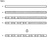
- Figure 1 shows in R1 to R4 different start condition before analyzing a sequence of droplets.
- the resistance (R) of a reservoir such as tubing depends on the inner medium and is particularly high for two-phase systems.
- R1 shows a tubing filled with air
- R2 shows a tubing filled with liquid
- R3 shows a tubing filled with only a few plugs
- R4 shows a tubing filled with many plugs.
- the hydrodynamic resistance in the setups shown in R1 to R4 is different.
- the tubing has to be filled with "dummy" plugs or droplets before the samples to be analyzed are generated to achieve a more constant resistance throughout the entire experiment (R5).
- the combinatorial samples are generated using e.g. a braille display chip, they are stored in a sequential fashion either in a tubing, capillary or microfluidic channel.
- this reservoir does not contain any plugs, but rather air or any priming liquid such as oil or water.
- moving this single-phase system typically requires a lower backpressure compared to moving an array of plugs (a two-phase system).
- the backpressure changes resulting in inhomogeneous sample sizes and inhomogeneous fractions of individual compounds within mixtures. This effect can be overcome by priming the system with "priming plugs" (e.g.
- the assay samples for analysis are generated.
- the assay samples will experience a much lower change in back pressure over time (as the number of total plugs in the system remains almost constant) and hence hardly change in size.
- the channels for all aqueous samples should have the same resistance, which can be achieved by the use of resistors (to compensate for differences in length, width or height).
- the channel downstream of the oil inlet must have a higher resistance than the channel between the drop maker (T-junction) and the sample outlet, as otherwise aqueous samples are occasionally pushed into the oil channel, changing the desired direction of flow (from the oil inlet to the sample outlet) inside the device.
- the size of the aqueous plugs or droplets also varies if the sample channels upstream of the drop maker have significantly different resistances. This is the case for the geometry shown in WO2013037962 as the length for the disclosed channels differs significantly.
- the instant disclosure provides a microfluidic device (chip) with sample channels upstream of the drop maker having the same length. Thus, varying sample sizes and varying fractions of individual compounds are avoided within a mixture.
- a fluidic resistor at the inlet of the immiscible phase (oil) can be used to avoid that the aqueous samples (optionally injected at much higher flow rates as compared to the oil) enter the oil channel upon opening of the valves (referring to the valves that control the flow of aqueous samples towards the drop maker).
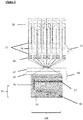
- Figure 2 shows a setup of a microfluidic device having fluidic resistors of the sample inlet channels 40 as well as a fluidic resistor of the immiscible phase channel 42.
- the fluidic resistors of the of the sample inlet channel 40 are used to adjust the same length for each sample inlet channel.
- the fluidic resistor of the immiscible phase 42 channel should ensure that the resistance of the immiscible phase channel is higher that the resistance of the outlet channel and/or read-out channel downstream of the droplet maker.
- Upstream of the fluidic resistors 40 are the sample inlets 25 and the waste outlet 30 arranged.
- the valves 20 are arranged in a so called valve module.
- a cell inlet 15 can be used to flush cells into the microfluidic device.
- the immiscble phase inlet 50 applies the immiscible phase 85.
- the droplet maker 100 comprises a T-junction 35 in the embodiment of figure 1 as well as a sample channel 29 and sample inlet channel 27.
- a droplet 80 is formed in the immiscible phase 85
- this requires additional outer channels (2D configuration) or a coaxial flow of oil (3D configuration) using an additional tubing around the reservoir into which oil is continuously injected and further flows into the microfluidic fusion chip, hence insulating the aqueous samples from the channel walls.
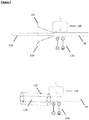
- FIG 3 shows schematically setups for the addition of additional substrates by additional immiscible phase inlets 120 to the samples.
- Such an addition requires a fusion step involving the injection of all sample plugs through a connection port for droplet fusion 130 into a second micro fluidic device.
- Fusion electrodes 110 can be arranged at the fusion chamber 90 as well as the substrate droplet maker 100. Wetting occurs frequently at the transition point from the tubing to the channel walls. This can be overcome by injecting additional "sheath oil” either in a 2D or 3D configuration (120 top and bottom).
- the samples are eventually flushed for the readout through a channel with a diameter comparable to that of the small droplets, so that each sample is measured individually without the possibility for two samples passing the detector at the same time.
- the diameter of the reservoir for incubation (tubing) cannot have such a small diameter, as this would result in resistances that cannot be handled experimentally.
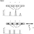
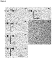
- Figure 4 shows in the upper part that plug hosting different cell numbers (A 68 cells; B 75 cells; C 53 cells) will cause different signal intensities in the readout. This can be overcome by single-cell analysis. If a particular sample has less cells, the number of positive peaks will be decreased, but their average intensity remains the same (bottom of figure 4 ). Experimentally this requires the use of large diameter reservoirs and small diameter readout channels for the signal read-out 150. The single cell droplets are spaced out with larger immiscible phase plugs 140.
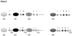
- Figure 5 shows that the readability of the binary barcodes (1 and 0) can be drastically improved by adding an additional "end of barcode" signal 230. This is particularly relevant as the number of digits per barcode is not constant, making it difficult to define the end of a barcode. Each barcode can be separated by immiscible phase plugs 200.
- Cross-contamination may occur in microfluidic devices making use of channels through which different reagents are flushed sequentially (based on the mixture to be generated), This is particularly relevant, as each channel upstream of the droplet maker has a certain dead volume, which remains after the generation of a particular mixture.
- the present disclosure provides a method for flushing out these remains and encapsulating them into a so-called "waste plug" in between each sample mixture.
- the method is based on splitting the generation of each new sample (each new combinatorial mixture) into two phases: First, the valve configuration for the generation of this particular mixture (VC i ) is set for just a very short time (a time period corresponding to less than the desired sample size for a given assay; e.g. Is) during which the remains of the previous sample are flushed into the droplet maker (mixing with and contaminating the current sample). Then the valve configuration is switched so that all aqueous liquids are sent to the waste while oil is still injected into the droplet maker. In consequence, an oil spacer is generated physically separating this newly generated waste plug from the next sample. Now the valve configuration is switched back to VC i .
- a very short time a time period corresponding to less than the desired sample size for a given assay; e.g. Is
- Figure 6 shows the encapsulation of a combinatorial sample into droplets without significant cross-contamination between the samples.
- An open valve 300 allows the respective sample to enter the channel and a closed valve 310 will stop the respective sample from entering the channel.
- A1-A5 After the encapsulation of a particular first combinatorial sample 320 the channels upstream of the drop maker are still filled with this sample and droplets thereof 321. These remains can be eliminated by shortly flushing the channels with a second sample mixture 330, followed by the injection of only an immiscible phase like oil. In consequence a waste plug 341 is generated from the mixture of samples 340, while the channels upstream of the drop maker are filled with pure 330. Hence opening the valves for the generation of 330 again results in the generation of a pure new combinatorial sample droplet 331, without any significant contamination from the previous sample.
- Part B of figure 6 shows a sequence of waste and sample plugs generated as described in A1 to A5.
- WO2013037962 also discloses the idea of sequentially injecting different compounds into at least one of the inlets of the combinatorial microfluidic chip. This can, for example, be achieved by connecting an auto sampler to the microfluidic chip. However, each compound aspirated by an auto sampler from microwell plates is transported to the microfluidic chip using a miscible carrier phase (e.g. buffer). This may cause two problems: The compound is diluted according to Tailor-Aris dispersion and furthermore the miscible phase is also injected into the combinatorial chip. However, for the generation of systematic combinatorial mixtures it is typically desirable dealing with pure, homogenously concentrated compounds.
- a miscible carrier phase e.g. buffer
- each compound plug coming from the auto sampler can be truncated and sent to the waste (comp. fig. 2 ).
- the instant disclosure provides a method installing a feedback loop between the auto sampler and the control of the braille display: Whenever the auto sampler injects a new compound into the tubing leading to the microfluidic chip, an electrical signal (relay signal) is send to the control software. After a constant delay in time for each compound, the dispersed compound plug arrives at the microfluidic chip, where its beginning and end is transferred to the waste by switching the valves accordingly (based on a pre-determined time sequence for the valve configurations). Due to the internal reference signal for each sample (the relay signal coming from the auto sampler), efficient synchronization between the two devices is guaranteed.
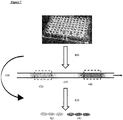
- Figure 7 shows the encapsulation of homogeneously concentrated compounds delivered by an auto sampler 400 in dispersed form spaced out by a miscible carrier phase.
- the (dispersed) beginning and end of each compound plug, as well as the spacer, can be sent to the waste by synchronizing the valve configuration of the braille display with the arrival of compound plugs at the microfluidic chip.
- an electrical signal serving as an internal reference point 450 is sent to the control software of the braille display.
- the valves are switched to allow for the delivery of the pure compound 421 and 441 to the drop maker.
- the valve configuration sends all liquid coming from the auto sampler to the waste.
- the arrow at the right side indicates the direction of flow.
Landscapes
- Chemical & Material Sciences (AREA)
- Chemical Kinetics & Catalysis (AREA)
- Health & Medical Sciences (AREA)
- Dispersion Chemistry (AREA)
- Analytical Chemistry (AREA)
- General Health & Medical Sciences (AREA)
- Hematology (AREA)
- Clinical Laboratory Science (AREA)
- Organic Chemistry (AREA)
- Automatic Analysis And Handling Materials Therefor (AREA)
- Physical Or Chemical Processes And Apparatus (AREA)
Claims (16)
- Mikrofluidvorrichtung zum Erzeugen von Tröpfchen von mindestens einer Probe in eine nicht mischbare Phase, die Vorrichtung umfasst einen Tröpfchenerzeuger (100), verbindend einen nicht mischbaren Phasenkanal (42) und einen Probenkanal mit einer Vielzahl von Probeneinlässen (25), verbunden mit einer Vielzahl von Probeneinlasskanälen (27), injizierend die mindestens eine Probe in den Probenkanal (29), wobei die Injektion der mindestens einen Probe durch eine Vielzahl von Probenventilen (20) gesteuert wird, so dass die mindestens eine Probe entweder zu einem Probenabfallauslass (30) oder in einen der Vielzahl von Probeneinlasskanälen (27) fließt, wobei die Vielzahl von Probeneinlasskanälen (27) den gleichen hydrodynamischen Widerstand aufweisen, sich aus der Länge, Höhe und Breite des Probeneinlasskanals (27) stromaufwärts des Tröpfchenerzeugers (100) ergebend,
die Mikrofluidvorrichtung weist einen Auslasskanal (60) stromabwärts des Tröpfchenerzeugers (100) auf, bei welchem die Tröpfchen in den Auslasskanal strömen, dadurch gekennzeichnet, dass
der hydrodynamische Widerstand des Auslasskanals (60) geringer ist als der hydrodynamische Widerstand des nicht mischbaren Phasenkanals (42), und bei welchem der hydrodynamische Widerstand des Auslasskanals, sich aus der Länge, Höhe und Breite des Auslasskanals ergebend, geringer ist als der hydrodynamische Widerstand der Probeneinlasskanäle. - Mikrofluidvorrichtung nach Anspruch 1, bei welcher einer der Vielzahl von Probeneinlasskanälen einen Probenfluidwiderstand zum Einstellen der Länge aufweist.
- Mikrofluidvorrichtung nach Anspruch 1, ferner umfassend einen nicht mischbaren Phasenfluidwiderstand (42) des nicht mischbaren Phasenkanals stromaufwärts des Tröpfchenerzeugers (100), um einen höheren Widerstand des nicht mischbaren Phasenkanals als den Widerstand des Probenkanals zu gewährleisten, um zu verhindern, dass die mindestens eine Probe in den nicht mischbaren Phasenkanal eintreten kann.
- Mikrofluidvorrichtung nach einem der Ansprüche 1 bis 3, bei welchem die Probentröpfchen in einen Auslesekanal fließen.
- Mikrofluidvorrichtung nach Anspruch 3, umfassend nicht mischbare Phaseneinlässe (120), die an einem Übergangspunkt angeordnet sind, an dem Proben aus mindestens einem von einem Probenspeicherreservoir in eine zweite Mikrofluidvorrichtung gespült werden.
- Mikrofluidvorrichtung nach Anspruch 4, bei welcher der Durchmesser des Auslesekanals in der Größe der Tröpfchen der mindestens einen Probe vergleichbar ist.
- Mikrofluidvorrichtung nach Anspruch 5, bei welcher die nicht mischbaren Phaseneinlässe (120) zusätzliche äußere Kanäle oder Kanäle, angeordnet koaxial mit dem Probenspeicher, sind.
- Verfahren zum Bereitstellen einer Sequenz von Tröpfchen von mindestens einer Probe, das Verfahren umfasst:- Bereitstellen von mindestens zwei Zusammensetzungen für eine Mikrofluidvorrichtung gemäß einem der Ansprüche 1 bis 7;- Herstellen mindestens einer kombinatorischen Probe aus den mindestens zwei Zusammensetzungen mit einer spezifischen Mischung der mindestens zwei Zusammensetzungen;- Injizieren der mindestens einen kombinatorischen Probe in die Mikrofluidvorrichtung;- Erzeugen in der Mikrofluidvorrichtung mindestens ein Tröpfchen der mindestens einen kombinatorischen Probe in einer nicht mischbaren Phase; und- Abscheiden des mindestens einen Tropfens mit mindestens einer nicht mischbaren Phase;- Bereitstellen mindestens eines Priming-Tropfens vor dem ersten des mindestens einen Tropfens der mindestens einen kombinatorischen Probe.
- Verfahren nach Anspruch 8, bei welchem die mindestens eine kombinatorische Probe vorzugsweise eine prokaryotische oder eukaryotische Zelle umfasst.
- Verfahren nach einem der Ansprüche 8 oder 9, bei welchem mindestens eine Zusammensetzung der mindestens zwei Zusammensetzungen aus einem Reservoir aspiriert oder transferiert wird.
- Verfahren nach einem der Ansprüche 8 bis 10, bei welchem eine kombinatorische Probe aus einem Reservoir in einen Auslesekanal mit einem Durchmesser übertragen wird, der nicht mehr als die Hälfte des Durchmessers des Reservoirs beträgt.
- Verfahren nach einem der Ansprüche 8 bis 11, bei welchem die Sequenz der Tröpfchen mit einem signifikant kleineren Durchmesser als der Auslasskanal erzeugt wird und bei welchem einzelne der Sequenz von Tröpfchen eingeschlossen oder von anderen der Sequenz von Tröpfchen getrennt werden, enthaltend eine andere Probenzusammensetzung, unter Verwendung von Pfropfen einer dritten nicht mischbaren Phase mit einem Durchmesser signifikant über dem Durchmesser des Reservoirs, um die einzelnen der Sequenz von Tröpfchen auszusondern.
- Verfahren nach einem der Ansprüche 8 bis 12, bei welchem direkt am Übergangspunkt von einer Mikrofluidvorrichtung zu einer zweiten Mikrofluidvorrichtung zusätzliche nicht mischbare Phaseneinlässe (120) verwendet werden, um die mindestens eine Probe in die zweite Mikrofluidvorrichtung zu spülen.
- Verfahren nach einem der Ansprüche 8 bis 13, bei welchem das Ansaugen der mindestens einen Zusammensetzung mit den Ventilen der Mikrofluidvorrichtung synchronisiert wird, so dass nur ein mittlerer Abschnitt der angesaugten mindestens einen Zusammensetzung zur Tröpfchenbildung verwendet wird.
- Verfahren nach einem der Ansprüche 8 bis 14, bei dem ein optischer Identifikator zwischen optischen Strichcodes erzeugt wird, wobei der optische Strichcode aufeinanderfolgende Tröpfchensequenzen umfasst, die unterschiedliche Eigenschaften der Tröpfchen verwenden, und wobei das Ende jedes optischen Strichcodes durch Tröpfchen mit einer einzigartigen Zusammensetzung markiert wird.
- Verfahren nach einem der Ansprüche 8 bis 15, bei welchem vor dem Injizieren der mindestens einen kombinatorischen Probe in die Mikrofluidvorrichtung die Reste einer vorhergehenden kombinatorischen Probe in den Tröpfchenerzeuger (100) gespült werden, wobei die nachfolgende kombinatorische Probe verwendet wird, um einen Abfallpfropfen zu erzeugen, gefolgt von der Übertragung aller wässrigen Flüssigkeiten auf den Abfall, während die nicht mischbare Phase noch in den Tröpfchenerzeuger (100) injiziert wird, so dass ein Abstandhalter der nicht mischbaren Phase den Abfallpfropfen von der nachfolgenden kombinatorischen Probe trennt.
Priority Applications (6)
| Application Number | Priority Date | Filing Date | Title |
|---|---|---|---|
| DK14186463.7T DK3000528T3 (da) | 2014-09-25 | 2014-09-25 | Mikrofluidindretning til generering af en sekvens af kombinatoriske prøver |
| ES14186463T ES2860938T3 (es) | 2014-09-25 | 2014-09-25 | Dispositivo microfluídico para la generación de muestras combinatorias |
| EP14186463.7A EP3000528B1 (de) | 2014-09-25 | 2014-09-25 | Mikrofluidische vorrichtung zur erzeugung von kombinatorischen proben |
| US15/513,826 US20170282145A1 (en) | 2014-09-25 | 2015-09-07 | Microfluidic Device for the Generation of Combinatorial Samples |
| PCT/EP2015/070400 WO2016045954A1 (en) | 2014-09-25 | 2015-09-07 | Microfluidic device for the generation of combinatorial samples |
| CA2962482A CA2962482C (en) | 2014-09-25 | 2015-09-07 | Microfluidic device for the generation of combinatorial samples |
Applications Claiming Priority (1)
| Application Number | Priority Date | Filing Date | Title |
|---|---|---|---|
| EP14186463.7A EP3000528B1 (de) | 2014-09-25 | 2014-09-25 | Mikrofluidische vorrichtung zur erzeugung von kombinatorischen proben |
Publications (2)
| Publication Number | Publication Date |
|---|---|
| EP3000528A1 EP3000528A1 (de) | 2016-03-30 |
| EP3000528B1 true EP3000528B1 (de) | 2020-12-16 |
Family
ID=51610032
Family Applications (1)
| Application Number | Title | Priority Date | Filing Date |
|---|---|---|---|
| EP14186463.7A Active EP3000528B1 (de) | 2014-09-25 | 2014-09-25 | Mikrofluidische vorrichtung zur erzeugung von kombinatorischen proben |
Country Status (6)
| Country | Link |
|---|---|
| US (1) | US20170282145A1 (de) |
| EP (1) | EP3000528B1 (de) |
| CA (1) | CA2962482C (de) |
| DK (1) | DK3000528T3 (de) |
| ES (1) | ES2860938T3 (de) |
| WO (1) | WO2016045954A1 (de) |
Families Citing this family (7)
| Publication number | Priority date | Publication date | Assignee | Title |
|---|---|---|---|---|
| CN105008895B (zh) | 2012-10-15 | 2019-02-15 | 纳诺赛莱克特生物医药股份有限公司 | 颗粒分选的系统、设备和方法 |
| EP3351302B1 (de) * | 2017-01-18 | 2021-05-05 | Biomillenia SAS | Mikrofluidisches system und verfahren mit genau gesteuerten inkubationszeiten und zuständen |
| CN110945139B (zh) | 2017-05-18 | 2023-09-05 | 10X基因组学有限公司 | 用于分选液滴和珠的方法和系统 |
| US10544413B2 (en) | 2017-05-18 | 2020-01-28 | 10X Genomics, Inc. | Methods and systems for sorting droplets and beads |
| US20190064173A1 (en) | 2017-08-22 | 2019-02-28 | 10X Genomics, Inc. | Methods of producing droplets including a particle and an analyte |
| WO2019083852A1 (en) | 2017-10-26 | 2019-05-02 | 10X Genomics, Inc. | MICROFLUIDIC CHANNEL NETWORKS FOR PARTITIONING |
| CN111068799B (zh) | 2018-10-18 | 2021-03-23 | 浙江达普生物科技有限公司 | 用于产生液滴的微流体通路及其应用 |
Family Cites Families (7)
| Publication number | Priority date | Publication date | Assignee | Title |
|---|---|---|---|---|
| US5856174A (en) * | 1995-06-29 | 1999-01-05 | Affymetrix, Inc. | Integrated nucleic acid diagnostic device |
| US7901939B2 (en) * | 2002-05-09 | 2011-03-08 | University Of Chicago | Method for performing crystallization and reactions in pressure-driven fluid plugs |
| WO2004081741A2 (en) | 2003-03-10 | 2004-09-23 | The Regents Of The University Of Michigan | Integrated microfluidic control employing programmable tactile actuators |
| NL1026261C2 (nl) * | 2004-05-25 | 2005-11-28 | Nanomi B V | Sproei inrichting met een nozzleplaat voorzien van structuren ter bevordering van self-breakup, een nozzleplaat, alsmede werkwijzen ter vervaardiging en toepassing van een dergelijke nozzleplaat. |
| JP2009536313A (ja) | 2006-01-11 | 2009-10-08 | レインダンス テクノロジーズ, インコーポレイテッド | ナノリアクターの形成および制御において使用するマイクロ流体デバイスおよび方法 |
| US20120283108A1 (en) * | 2011-05-03 | 2012-11-08 | Sampas Nicholas M | Method for phased genotyping of a diploid genome |
| GB201115895D0 (en) | 2011-09-14 | 2011-10-26 | Embl | Microfluidic device |
-
2014
- 2014-09-25 EP EP14186463.7A patent/EP3000528B1/de active Active
- 2014-09-25 ES ES14186463T patent/ES2860938T3/es active Active
- 2014-09-25 DK DK14186463.7T patent/DK3000528T3/da active
-
2015
- 2015-09-07 US US15/513,826 patent/US20170282145A1/en not_active Abandoned
- 2015-09-07 CA CA2962482A patent/CA2962482C/en active Active
- 2015-09-07 WO PCT/EP2015/070400 patent/WO2016045954A1/en not_active Ceased
Non-Patent Citations (1)
| Title |
|---|
| None * |
Also Published As
| Publication number | Publication date |
|---|---|
| CA2962482C (en) | 2022-10-04 |
| US20170282145A1 (en) | 2017-10-05 |
| EP3000528A1 (de) | 2016-03-30 |
| WO2016045954A1 (en) | 2016-03-31 |
| DK3000528T3 (da) | 2021-03-15 |
| CA2962482A1 (en) | 2016-03-31 |
| ES2860938T3 (es) | 2021-10-05 |
Similar Documents
| Publication | Publication Date | Title |
|---|---|---|
| EP3000528B1 (de) | Mikrofluidische vorrichtung zur erzeugung von kombinatorischen proben | |
| KR102168053B1 (ko) | 고속 온 디맨드 미세유체 액적 생성 및 조작 | |
| Clausell-Tormos et al. | An automated two-phase microfluidic system for kinetic analyses and the screening of compound libraries | |
| Tran et al. | From tubes to drops: droplet-based microfluidics for ultrahigh-throughput biology | |
| US9138700B2 (en) | Accurate and rapid micromixer for integrated microfluidic devices | |
| Adamson et al. | Production of arrays of chemically distinct nanolitre plugs via repeated splitting in microfluidic devices | |
| US10739366B2 (en) | System and method for screening a library of samples | |
| Zeng et al. | Microvalve-actuated precise control of individual droplets in microfluidic devices | |
| US7094379B2 (en) | Device for parallel and synchronous injection for sequential injection of different reagents | |
| US10745741B2 (en) | Cell barcoding in microfluidics | |
| US20030210607A1 (en) | On chip dilution system | |
| US12290811B2 (en) | Microfluidic serial dilution platform based well-plate using an oil-free immiscible phase driven by manual or electronic pipettors | |
| Compera et al. | Upscaling of pneumatic membrane valves for the integration of 3D cell cultures on chip | |
| KR20110046867A (ko) | 기체 제공부를 포함하는 미세 유동 장치, 및 이를 이용한 액체 혼합 방법 및 에멀젼 형성 방법 | |
| Rhee et al. | Versatile on-demand droplet generation for controlled encapsulation | |
| WO2013021035A1 (en) | Microfluids for cell-based assays | |
| Cowell et al. | Drop‐by‐Drop Addition of Reagents to a Double Emulsion | |
| JP7171739B2 (ja) | マイクロ流体デバイスおよび該マイクロ流体デバイスを運転する方法 | |
| Harriot et al. | Programmable Control of Nanoliter Droplet Arrays Using Membrane Displacement Traps | |
| CA2988490C (en) | Cell barcoding in microfluidics | |
| CN120897800A (zh) | 用于在载体相内产生组合微区室的装置和方法 | |
| Babahosseini et al. | A Scalable Random Access Micro-traps Array for Formation, Selective Retrieval and Capturing of Individual Droplets | |
| Zec et al. | Microfluidic Combinatorial Screening Platform | |
| Wang | Microfluidic droplet formation and manipulations for microdroplets used as miniaturized laboratories |
Legal Events
| Date | Code | Title | Description |
|---|---|---|---|
| PUAI | Public reference made under article 153(3) epc to a published international application that has entered the european phase |
Free format text: ORIGINAL CODE: 0009012 |
|
| AK | Designated contracting states |
Kind code of ref document: A1 Designated state(s): AL AT BE BG CH CY CZ DE DK EE ES FI FR GB GR HR HU IE IS IT LI LT LU LV MC MK MT NL NO PL PT RO RS SE SI SK SM TR |
|
| AX | Request for extension of the european patent |
Extension state: BA ME |
|
| 17P | Request for examination filed |
Effective date: 20160930 |
|
| RBV | Designated contracting states (corrected) |
Designated state(s): AL AT BE BG CH CY CZ DE DK EE ES FI FR GB GR HR HU IE IS IT LI LT LU LV MC MK MT NL NO PL PT RO RS SE SI SK SM TR |
|
| STAA | Information on the status of an ep patent application or granted ep patent |
Free format text: STATUS: EXAMINATION IS IN PROGRESS |
|
| 17Q | First examination report despatched |
Effective date: 20180730 |
|
| GRAP | Despatch of communication of intention to grant a patent |
Free format text: ORIGINAL CODE: EPIDOSNIGR1 |
|
| STAA | Information on the status of an ep patent application or granted ep patent |
Free format text: STATUS: GRANT OF PATENT IS INTENDED |
|
| INTG | Intention to grant announced |
Effective date: 20200708 |
|
| GRAS | Grant fee paid |
Free format text: ORIGINAL CODE: EPIDOSNIGR3 |
|
| GRAA | (expected) grant |
Free format text: ORIGINAL CODE: 0009210 |
|
| STAA | Information on the status of an ep patent application or granted ep patent |
Free format text: STATUS: THE PATENT HAS BEEN GRANTED |
|
| AK | Designated contracting states |
Kind code of ref document: B1 Designated state(s): AL AT BE BG CH CY CZ DE DK EE ES FI FR GB GR HR HU IE IS IT LI LT LU LV MC MK MT NL NO PL PT RO RS SE SI SK SM TR |
|
| REG | Reference to a national code |
Ref country code: GB Ref legal event code: FG4D |
|
| REG | Reference to a national code |
Ref country code: IE Ref legal event code: FG4D |
|
| REG | Reference to a national code |
Ref country code: DE Ref legal event code: R096 Ref document number: 602014073358 Country of ref document: DE |
|
| REG | Reference to a national code |
Ref country code: AT Ref legal event code: REF Ref document number: 1345095 Country of ref document: AT Kind code of ref document: T Effective date: 20210115 |
|
| REG | Reference to a national code |
Ref country code: DK Ref legal event code: T3 Effective date: 20210310 Ref country code: CH Ref legal event code: NV Representative=s name: SONNENBERG HARRISON, CH |
|
| REG | Reference to a national code |
Ref country code: SE Ref legal event code: TRGR |
|
| PG25 | Lapsed in a contracting state [announced via postgrant information from national office to epo] |
Ref country code: GR Free format text: LAPSE BECAUSE OF FAILURE TO SUBMIT A TRANSLATION OF THE DESCRIPTION OR TO PAY THE FEE WITHIN THE PRESCRIBED TIME-LIMIT Effective date: 20210317 Ref country code: FI Free format text: LAPSE BECAUSE OF FAILURE TO SUBMIT A TRANSLATION OF THE DESCRIPTION OR TO PAY THE FEE WITHIN THE PRESCRIBED TIME-LIMIT Effective date: 20201216 Ref country code: RS Free format text: LAPSE BECAUSE OF FAILURE TO SUBMIT A TRANSLATION OF THE DESCRIPTION OR TO PAY THE FEE WITHIN THE PRESCRIBED TIME-LIMIT Effective date: 20201216 |
|
| REG | Reference to a national code |
Ref country code: NO Ref legal event code: T2 Effective date: 20201216 |
|
| REG | Reference to a national code |
Ref country code: NL Ref legal event code: MP Effective date: 20201216 |
|
| PG25 | Lapsed in a contracting state [announced via postgrant information from national office to epo] |
Ref country code: LV Free format text: LAPSE BECAUSE OF FAILURE TO SUBMIT A TRANSLATION OF THE DESCRIPTION OR TO PAY THE FEE WITHIN THE PRESCRIBED TIME-LIMIT Effective date: 20201216 Ref country code: BG Free format text: LAPSE BECAUSE OF FAILURE TO SUBMIT A TRANSLATION OF THE DESCRIPTION OR TO PAY THE FEE WITHIN THE PRESCRIBED TIME-LIMIT Effective date: 20210316 |
|
| PG25 | Lapsed in a contracting state [announced via postgrant information from national office to epo] |
Ref country code: NL Free format text: LAPSE BECAUSE OF FAILURE TO SUBMIT A TRANSLATION OF THE DESCRIPTION OR TO PAY THE FEE WITHIN THE PRESCRIBED TIME-LIMIT Effective date: 20201216 Ref country code: HR Free format text: LAPSE BECAUSE OF FAILURE TO SUBMIT A TRANSLATION OF THE DESCRIPTION OR TO PAY THE FEE WITHIN THE PRESCRIBED TIME-LIMIT Effective date: 20201216 |
|
| REG | Reference to a national code |
Ref country code: LT Ref legal event code: MG9D |
|
| PG25 | Lapsed in a contracting state [announced via postgrant information from national office to epo] |
Ref country code: PT Free format text: LAPSE BECAUSE OF FAILURE TO SUBMIT A TRANSLATION OF THE DESCRIPTION OR TO PAY THE FEE WITHIN THE PRESCRIBED TIME-LIMIT Effective date: 20210416 Ref country code: RO Free format text: LAPSE BECAUSE OF FAILURE TO SUBMIT A TRANSLATION OF THE DESCRIPTION OR TO PAY THE FEE WITHIN THE PRESCRIBED TIME-LIMIT Effective date: 20201216 Ref country code: SK Free format text: LAPSE BECAUSE OF FAILURE TO SUBMIT A TRANSLATION OF THE DESCRIPTION OR TO PAY THE FEE WITHIN THE PRESCRIBED TIME-LIMIT Effective date: 20201216 Ref country code: LT Free format text: LAPSE BECAUSE OF FAILURE TO SUBMIT A TRANSLATION OF THE DESCRIPTION OR TO PAY THE FEE WITHIN THE PRESCRIBED TIME-LIMIT Effective date: 20201216 Ref country code: SM Free format text: LAPSE BECAUSE OF FAILURE TO SUBMIT A TRANSLATION OF THE DESCRIPTION OR TO PAY THE FEE WITHIN THE PRESCRIBED TIME-LIMIT Effective date: 20201216 Ref country code: CZ Free format text: LAPSE BECAUSE OF FAILURE TO SUBMIT A TRANSLATION OF THE DESCRIPTION OR TO PAY THE FEE WITHIN THE PRESCRIBED TIME-LIMIT Effective date: 20201216 Ref country code: EE Free format text: LAPSE BECAUSE OF FAILURE TO SUBMIT A TRANSLATION OF THE DESCRIPTION OR TO PAY THE FEE WITHIN THE PRESCRIBED TIME-LIMIT Effective date: 20201216 |
|
| PG25 | Lapsed in a contracting state [announced via postgrant information from national office to epo] |
Ref country code: PL Free format text: LAPSE BECAUSE OF FAILURE TO SUBMIT A TRANSLATION OF THE DESCRIPTION OR TO PAY THE FEE WITHIN THE PRESCRIBED TIME-LIMIT Effective date: 20201216 |
|
| REG | Reference to a national code |
Ref country code: DE Ref legal event code: R097 Ref document number: 602014073358 Country of ref document: DE |
|
| PG25 | Lapsed in a contracting state [announced via postgrant information from national office to epo] |
Ref country code: IS Free format text: LAPSE BECAUSE OF FAILURE TO SUBMIT A TRANSLATION OF THE DESCRIPTION OR TO PAY THE FEE WITHIN THE PRESCRIBED TIME-LIMIT Effective date: 20210416 |
|
| PLBE | No opposition filed within time limit |
Free format text: ORIGINAL CODE: 0009261 |
|
| STAA | Information on the status of an ep patent application or granted ep patent |
Free format text: STATUS: NO OPPOSITION FILED WITHIN TIME LIMIT |
|
| PG25 | Lapsed in a contracting state [announced via postgrant information from national office to epo] |
Ref country code: AL Free format text: LAPSE BECAUSE OF FAILURE TO SUBMIT A TRANSLATION OF THE DESCRIPTION OR TO PAY THE FEE WITHIN THE PRESCRIBED TIME-LIMIT Effective date: 20201216 |
|
| 26N | No opposition filed |
Effective date: 20210917 |
|
| PG25 | Lapsed in a contracting state [announced via postgrant information from national office to epo] |
Ref country code: SI Free format text: LAPSE BECAUSE OF FAILURE TO SUBMIT A TRANSLATION OF THE DESCRIPTION OR TO PAY THE FEE WITHIN THE PRESCRIBED TIME-LIMIT Effective date: 20201216 |
|
| REG | Reference to a national code |
Ref country code: BE Ref legal event code: MM Effective date: 20210930 |
|
| PG25 | Lapsed in a contracting state [announced via postgrant information from national office to epo] |
Ref country code: MC Free format text: LAPSE BECAUSE OF FAILURE TO SUBMIT A TRANSLATION OF THE DESCRIPTION OR TO PAY THE FEE WITHIN THE PRESCRIBED TIME-LIMIT Effective date: 20201216 |
|
| PG25 | Lapsed in a contracting state [announced via postgrant information from national office to epo] |
Ref country code: LU Free format text: LAPSE BECAUSE OF NON-PAYMENT OF DUE FEES Effective date: 20210925 Ref country code: IE Free format text: LAPSE BECAUSE OF NON-PAYMENT OF DUE FEES Effective date: 20210925 Ref country code: BE Free format text: LAPSE BECAUSE OF NON-PAYMENT OF DUE FEES Effective date: 20210930 |
|
| PG25 | Lapsed in a contracting state [announced via postgrant information from national office to epo] |
Ref country code: HU Free format text: LAPSE BECAUSE OF FAILURE TO SUBMIT A TRANSLATION OF THE DESCRIPTION OR TO PAY THE FEE WITHIN THE PRESCRIBED TIME-LIMIT; INVALID AB INITIO Effective date: 20140925 |
|
| PG25 | Lapsed in a contracting state [announced via postgrant information from national office to epo] |
Ref country code: CY Free format text: LAPSE BECAUSE OF FAILURE TO SUBMIT A TRANSLATION OF THE DESCRIPTION OR TO PAY THE FEE WITHIN THE PRESCRIBED TIME-LIMIT Effective date: 20201216 |
|
| PG25 | Lapsed in a contracting state [announced via postgrant information from national office to epo] |
Ref country code: MK Free format text: LAPSE BECAUSE OF FAILURE TO SUBMIT A TRANSLATION OF THE DESCRIPTION OR TO PAY THE FEE WITHIN THE PRESCRIBED TIME-LIMIT Effective date: 20201216 |
|
| PG25 | Lapsed in a contracting state [announced via postgrant information from national office to epo] |
Ref country code: MT Free format text: LAPSE BECAUSE OF FAILURE TO SUBMIT A TRANSLATION OF THE DESCRIPTION OR TO PAY THE FEE WITHIN THE PRESCRIBED TIME-LIMIT Effective date: 20201216 |
|
| REG | Reference to a national code |
Ref country code: AT Ref legal event code: UEP Ref document number: 1345095 Country of ref document: AT Kind code of ref document: T Effective date: 20201216 |
|
| REG | Reference to a national code |
Ref country code: CH Ref legal event code: U11 Free format text: ST27 STATUS EVENT CODE: U-0-0-U10-U11 (AS PROVIDED BY THE NATIONAL OFFICE) Effective date: 20251001 |
|
| PGFP | Annual fee paid to national office [announced via postgrant information from national office to epo] |
Ref country code: DK Payment date: 20250922 Year of fee payment: 12 |
|
| PGFP | Annual fee paid to national office [announced via postgrant information from national office to epo] |
Ref country code: NO Payment date: 20250919 Year of fee payment: 12 |
|
| PGFP | Annual fee paid to national office [announced via postgrant information from national office to epo] |
Ref country code: GB Payment date: 20250903 Year of fee payment: 12 |
|
| PGFP | Annual fee paid to national office [announced via postgrant information from national office to epo] |
Ref country code: FR Payment date: 20250926 Year of fee payment: 12 Ref country code: AT Payment date: 20250918 Year of fee payment: 12 |
|
| PGFP | Annual fee paid to national office [announced via postgrant information from national office to epo] |
Ref country code: SE Payment date: 20250922 Year of fee payment: 12 |
|
| PG25 | Lapsed in a contracting state [announced via postgrant information from national office to epo] |
Ref country code: TR Free format text: LAPSE BECAUSE OF FAILURE TO SUBMIT A TRANSLATION OF THE DESCRIPTION OR TO PAY THE FEE WITHIN THE PRESCRIBED TIME-LIMIT Effective date: 20201216 |
|
| PGFP | Annual fee paid to national office [announced via postgrant information from national office to epo] |
Ref country code: DE Payment date: 20250929 Year of fee payment: 12 |
|
| PGFP | Annual fee paid to national office [announced via postgrant information from national office to epo] |
Ref country code: IT Payment date: 20250930 Year of fee payment: 12 |
|
| PGFP | Annual fee paid to national office [announced via postgrant information from national office to epo] |
Ref country code: CH Payment date: 20251001 Year of fee payment: 12 |
|
| PGFP | Annual fee paid to national office [announced via postgrant information from national office to epo] |
Ref country code: ES Payment date: 20251020 Year of fee payment: 12 |