EP3000378A1 - Endoscope - Google Patents
Endoscope Download PDFInfo
- Publication number
- EP3000378A1 EP3000378A1 EP14800911.1A EP14800911A EP3000378A1 EP 3000378 A1 EP3000378 A1 EP 3000378A1 EP 14800911 A EP14800911 A EP 14800911A EP 3000378 A1 EP3000378 A1 EP 3000378A1
- Authority
- EP
- European Patent Office
- Prior art keywords
- observation
- optical system
- illumination optical
- optical systems
- brightness
- Prior art date
- Legal status (The legal status is an assumption and is not a legal conclusion. Google has not performed a legal analysis and makes no representation as to the accuracy of the status listed.)
- Granted
Links
- 230000003287 optical effect Effects 0.000 claims abstract description 205
- 238000005286 illumination Methods 0.000 claims abstract description 120
- 230000014509 gene expression Effects 0.000 claims abstract description 100
- 238000003780 insertion Methods 0.000 claims abstract description 22
- 230000037431 insertion Effects 0.000 claims abstract description 22
- 230000002349 favourable effect Effects 0.000 abstract description 31
- 230000002093 peripheral effect Effects 0.000 description 23
- 238000010586 diagram Methods 0.000 description 12
- 239000000835 fiber Substances 0.000 description 6
- 239000011521 glass Substances 0.000 description 6
- 238000004140 cleaning Methods 0.000 description 4
- 230000006866 deterioration Effects 0.000 description 4
- 230000000694 effects Effects 0.000 description 3
- 230000003902 lesion Effects 0.000 description 3
- 230000001629 suppression Effects 0.000 description 3
- HQLZFBUAULNEGP-UHFFFAOYSA-N CCCC(CC)N Chemical compound CCCC(CC)N HQLZFBUAULNEGP-UHFFFAOYSA-N 0.000 description 1
- 239000012141 concentrate Substances 0.000 description 1
- 239000012530 fluid Substances 0.000 description 1
- 238000012423 maintenance Methods 0.000 description 1
- 239000000523 sample Substances 0.000 description 1
- 230000002195 synergetic effect Effects 0.000 description 1
Images


Classifications
-
- A—HUMAN NECESSITIES
- A61—MEDICAL OR VETERINARY SCIENCE; HYGIENE
- A61B—DIAGNOSIS; SURGERY; IDENTIFICATION
- A61B1/00—Instruments for performing medical examinations of the interior of cavities or tubes of the body by visual or photographical inspection, e.g. endoscopes; Illuminating arrangements therefor
- A61B1/00064—Constructional details of the endoscope body
- A61B1/00071—Insertion part of the endoscope body
- A61B1/0008—Insertion part of the endoscope body characterised by distal tip features
- A61B1/00096—Optical elements
-
- A—HUMAN NECESSITIES
- A61—MEDICAL OR VETERINARY SCIENCE; HYGIENE
- A61B—DIAGNOSIS; SURGERY; IDENTIFICATION
- A61B1/00—Instruments for performing medical examinations of the interior of cavities or tubes of the body by visual or photographical inspection, e.g. endoscopes; Illuminating arrangements therefor
- A61B1/00163—Optical arrangements
- A61B1/00188—Optical arrangements with focusing or zooming features
-
- A—HUMAN NECESSITIES
- A61—MEDICAL OR VETERINARY SCIENCE; HYGIENE
- A61B—DIAGNOSIS; SURGERY; IDENTIFICATION
- A61B1/00—Instruments for performing medical examinations of the interior of cavities or tubes of the body by visual or photographical inspection, e.g. endoscopes; Illuminating arrangements therefor
- A61B1/04—Instruments for performing medical examinations of the interior of cavities or tubes of the body by visual or photographical inspection, e.g. endoscopes; Illuminating arrangements therefor combined with photographic or television appliances
- A61B1/05—Instruments for performing medical examinations of the interior of cavities or tubes of the body by visual or photographical inspection, e.g. endoscopes; Illuminating arrangements therefor combined with photographic or television appliances characterised by the image sensor, e.g. camera, being in the distal end portion
-
- A—HUMAN NECESSITIES
- A61—MEDICAL OR VETERINARY SCIENCE; HYGIENE
- A61B—DIAGNOSIS; SURGERY; IDENTIFICATION
- A61B1/00—Instruments for performing medical examinations of the interior of cavities or tubes of the body by visual or photographical inspection, e.g. endoscopes; Illuminating arrangements therefor
- A61B1/06—Instruments for performing medical examinations of the interior of cavities or tubes of the body by visual or photographical inspection, e.g. endoscopes; Illuminating arrangements therefor with illuminating arrangements
- A61B1/0661—Endoscope light sources
- A61B1/0676—Endoscope light sources at distal tip of an endoscope
-
- A—HUMAN NECESSITIES
- A61—MEDICAL OR VETERINARY SCIENCE; HYGIENE
- A61B—DIAGNOSIS; SURGERY; IDENTIFICATION
- A61B1/00—Instruments for performing medical examinations of the interior of cavities or tubes of the body by visual or photographical inspection, e.g. endoscopes; Illuminating arrangements therefor
- A61B1/06—Instruments for performing medical examinations of the interior of cavities or tubes of the body by visual or photographical inspection, e.g. endoscopes; Illuminating arrangements therefor with illuminating arrangements
- A61B1/07—Instruments for performing medical examinations of the interior of cavities or tubes of the body by visual or photographical inspection, e.g. endoscopes; Illuminating arrangements therefor with illuminating arrangements using light-conductive means, e.g. optical fibres
-
- G—PHYSICS
- G02—OPTICS
- G02B—OPTICAL ELEMENTS, SYSTEMS OR APPARATUS
- G02B23/00—Telescopes, e.g. binoculars; Periscopes; Instruments for viewing the inside of hollow bodies; Viewfinders; Optical aiming or sighting devices
- G02B23/24—Instruments or systems for viewing the inside of hollow bodies, e.g. fibrescopes
- G02B23/2407—Optical details
- G02B23/2423—Optical details of the distal end
- G02B23/243—Objectives for endoscopes
-
- G—PHYSICS
- G02—OPTICS
- G02B—OPTICAL ELEMENTS, SYSTEMS OR APPARATUS
- G02B23/00—Telescopes, e.g. binoculars; Periscopes; Instruments for viewing the inside of hollow bodies; Viewfinders; Optical aiming or sighting devices
- G02B23/24—Instruments or systems for viewing the inside of hollow bodies, e.g. fibrescopes
- G02B23/26—Instruments or systems for viewing the inside of hollow bodies, e.g. fibrescopes using light guides
Definitions
- the present invention relates to an endoscope including illumination optical systems and an observation optical system.
- an illumination optical system for illuminating a subject an observation optical system including, at a distal end face thereof, an optical member for receiving incoming light from the subject, a channel that guides a treatment instrument, and a nozzle for cleaning dirt adhering to a lens surface of the image pickup optical system are provided.
- An endoscope including an observation optical system that allows magnified close observation allows not only normal observation but also close observation by moving a part of lenses in the observation optical system and thereby changing a focal length.
- a same illumination optical system is used for both normal observation and close observation, in particular, in a close observation in which a distance to a subject is no more than 2 mm, a peripheral part of a screen is brighter than a center of the same because of the layout of the illumination optical system. Therefore, when a subject to be focused on is positioned at the center part, a favorable observation cannot be performed because of insufficient distribution of illuminating light.
- PTL 1 discloses an endoscope that provides only small illumination unevenness in a magnified close observation and thus enables illumination of a subject with sufficient brightness by setting a variable range of a best focal position within a range in which illuminating light beams emitted from a plurality of illumination windows overlap.
- PTL 2 discloses an endoscope that minimizes unevenness in an observation area in close observation by providing illumination means at respective positions on opposite sides of an observation optical system at which an illuminance of a peripheral part of the observation area is no more than twice an illuminance of a center part of the observation area.
- the endoscope disclosed in PTL 1 requires a best focal position to be set at a distance that provides sufficiently wide distribution of light from the illumination optical systems, making it difficult to bring the endoscope close to a subject, and thus, is not suitable for magnified observation.
- the endoscope disclosed in PTL 2 ensures light distribution by providing a large distance between the observation optical system and the illumination optical systems, resulting in an increase in diameter of a distal end of the endoscope.
- the present invention has been made in view of the aforementioned circumstances, and an object of the present invention is to provide an endoscope that ensures sufficient light distribution in both of normal observation and close observation, enabling favorable observation.
- the present invention provides the following solutions.
- An aspect of the present invention provides an endoscope including: an observation optical system including a plurality of lenses and having a function that allows a magnified observation close to a subject; and a plurality of illumination optical systems each including a plurality of lenses and illuminating the subject with illuminating light, wherein in a close observation in which a distance between a distal end face of the insertion portion and the subject is an arbitrary distance of from 1.5 mm to 2.5 mm, where I TM is a maximum brightness within an observation view field angle and I TC is a center brightness, and in a normal observation in which the distance between the distal end face of the insertion portion and the subject is 50 mm, where I WC is a center brightness and I WS is a brightness at a position of 80% of a maximum view angle, the following conditional expressions are satisfied: 0.3 ⁇ I TC / I TM ⁇ 0.45 0.15 ⁇ I WS / I WC ⁇ 0.25 and 0.3 ⁇ f L f T /
- a ratio of a brightness of a center part relative to a peripheral part can be made high also in a magnified close observation, enabling favorable observation.
- a distance between the observation optical system and a subject is smaller than a distance between the observation optical system and each illumination optical system, and thus, the brightness of the peripheral part is larger than that of the center part.
- a lesion or the like to be focused on is usually brought to the center part, and thus, favorable observation cannot be performed unless the ratio of the brightness of the center part relative to that of the peripheral part is high.
- satisfaction of conditional expression (1) can make the ratio of the brightness of the center part relative to that of the peripheral part high also in magnified close observation, allowing favorable observation.
- a brightness of a center part is larger than that of a peripheral part.
- a subject having a depth is observed, and an excessive increase in brightness of the peripheral part may hinder favorable observation in the depth direction.
- an excessive decrease in brightness of the peripheral part may hinder favorable observation of the peripheral part, and thus it is necessary to balance the brightness for observation in the depth direction and the brightness for observation of the peripheral part.
- the endoscope is configured so as to satisfy conditional expression (2).
- conditional expression (3) it is necessary to set the focal length of each illumination optical system so as to conform to a focal length of the observation optical system, and also to satisfy conditional expression (3).
- conditional expression (3) the focal length of the observation optical system and the focal length of each illumination optical system are determined, enabling provision of a well-balanced light distribution capability for both of distant observation and close observation.
- At least two illumination optical systems of the plurality of illumination optical systems satisfy the following conditional expressions: 8 ⁇ r 1 2 / f L f T ⁇ 16 and 8 ⁇ r 2 2 / f L f T ⁇ 16 where each of r 1 and r 2 is a distance between a center of a lens disposed farthest on an object side of the observation optical system, and a center of the lens disposed farthest on the object side of each of the illumination optical systems.
- the distance between the observation optical system and each illumination optical system falls within a desired range, enabling setting of a proper light distribution capability of the illumination optical system.
- the observation optical system satisfies the following conditional expression: 0.8 ⁇ f T F FT / f W F FW ⁇ 1.1 where f W is a focal length of the entire system in a normal observation state, F FT is a front-side focal position in a magnified close observation state, and F FW is a front-side focal position in a normal observation state.
- the view field range can be made to fall within a proper range, enabling provision of even light distribution and thus favorable observation.
- the observation optical system satisfies the following conditional expression: 0.3 ⁇ 1 ⁇ ⁇ / I H ⁇ 0.45 where ⁇ is a paraxial magnifying power of the observation optical system in a maximum magnification.
- the observation optical system satisfies the following conditional expression: 0.25 ⁇ I H / 1000 P ⁇ 0.5 where P is a pixel pitch of an image pickup device included in the observation optical system.
- an image pickup device including a sufficient number of pixels can be employed, enabling favorable observation.
- At least two illumination optical systems of the plurality of illumination optical systems each include three convex lenses and satisfy the following conditional expression: 1.4 ⁇ f L 1 / f L ⁇ 3.2 where f L1 is a focal length of a lens that is farthest on an object side of each illumination optical system.
- a brightness in a direction toward a center at a distance of 50 mm is 1, a brightness ⁇ ( ⁇ ) at an arbitrary angle ⁇ (°) satisfies the following conditional expression: 0.21 ⁇ ⁇ 50 / ⁇ 25 ⁇ 0.39
- At least two illumination optical systems of the plurality of illumination optical systems satisfy the following conditional expressions: 0.8 ⁇ r 1 / r 2 ⁇ 1.2 165 ⁇ ⁇ 1 ⁇ ⁇ 2 ⁇ 180 and 0.06 ⁇ r 1 r 2 / ⁇ 2 ⁇ 0.15 where each of ⁇ 1 and ⁇ 2 is an azimuth relative to the direction toward the center, and ⁇ is a diameter of a distal end of the endoscope.
- the illumination optical systems are illumination optical systems that are identical to one another and each include three convex lenses, and satisfy the following conditional expressions: 0.8 ⁇ min r 1 r 2 r 3 / Max r 1 r 2 r 3 ⁇ 1.0 where each of r 1 , r 2 and r 3 is a distance between a center of a lens disposed farthest on an object side of the observation optical system, and a center of the lens disposed farthest on the object side of the relevant illumination optical system.
- the present invention provides the effect of ensuring sufficient light distribution and thereby allowing favorable observation in both normal observation and close observation.
- Fig. 1 illustrates a front face of a distal end portion of an insertion portion of an endoscope, and as illustrated in Fig. 1 , in the insertion portion, an observation optical system 1 that picks up an image of an observation target, a plurality of illumination optical systems 2 that each distribute illuminating light emitted from a non-illustrated light source and supplied via a light guide fiber, a channel 3 that guides a treatment instrument such as a forceps or a probe, and a nozzle 4 that supplies a fluid or air for cleaning to the observation optical system 1 and the illumination optical systems 2.
- an observation optical system 1 that picks up an image of an observation target
- a plurality of illumination optical systems 2 that each distribute illuminating light emitted from a non-illustrated light source and supplied via a light guide fiber
- a channel 3 that guides a treatment instrument such as a forceps or a probe
- a nozzle 4 that supplies a fluid or air for cleaning to the observation optical system 1 and the illumination optical
- each of r 1 to r 3 is a distance between a center of the observation optical system 1 and a center of the relevant illumination optical system 2.
- a counterclockwise direction is a positive direction.
- ⁇ 1 90°
- ⁇ 2 270°
- ⁇ 3 10°.
- an insertion diameters ⁇ of a distal end of the endoscope is a diameter of the distal end portion of the endoscope.
- a structure of the distal end portion of the endoscope may include a projecting odd-shape part 20 provided because of a physical structural object in the insertion portion, for example, where a channel cannot be fully accommodated in a round distal end portion.
- a maximum diameter portion is determined as ⁇ .
- the observation optical system 1 includes a plurality of lenses and has a function that allows a magnified observation close to a subject.
- a distance between the observation optical system 1 and the subject is smaller than a distance between the observation optical system 1 and each of the illumination optical systems 2, and thus, a brightness of a peripheral part is larger than that of a center part.
- a lesion to be focused on is usually positioned in the center part, favorable observation is hindered unless a ratio of the brightness of the center part relative to that of the peripheral part is high.
- the endoscope is configured so that in a close observation in which a distance between a distal end face of the insertion portion and the subject is an arbitrary distance of from 1.5 mm to 2.5 mm, where I TM is a maximum brightness within an observation view field angle and I TC is a center brightness, the following conditional expression is satisfied: 0.3 ⁇ I TC / I TM ⁇ 0.45
- conditional expression (1) If a value that is below the lower limit of conditional expression (1) is provided, the center part is dark, making it impossible to perform favorable observation when the endoscope is bought close to the subject. On the other hand, if a value exceeding the upper limit is provided, it is possible to perform favorable close observation; however, a distribution of light by each illumination optical system is wide, resulting in deterioration in capability of observation in a depth direction in normal observation.
- conditional expression (1) be satisfied with an arbitrary distance between 1.5 mm and 2.5 mm in depth in magnified close observation, and it is more desirable that conditional expression (1) be satisfied with a distance of no more than 2 mm because more favorable observation can be performed as a synergistic effect in combination with a magnified observation (in which a subject can more closely be observed with magnification).
- a brightness of a center part is larger than that of a peripheral part.
- a subject having a depth is observed, and an excessive increase in brightness of the peripheral part hinders favorable observation in the depth direction.
- an excessive decrease in brightness of the peripheral part hinders favorable observation of the peripheral part, and thus, it is necessary to balance the brightness for observation in the depth direction and the brightness for observation of the peripheral part.
- the endoscope is configured so that in a normal observation in which the distance between the distal end face of the insertion portion and the subject is 50 mm, where I CW is a center brightness and I WS is a brightness at a position of 80% of a maximum view angle, the following conditional expression is satisfied: 0.15 ⁇ I WS / I WC ⁇ 0.25
- conditional expression (2) If a value that is below the lower limit of conditional expression (2) is provided, the peripheral part is excessively dark in a normal observation and sufficient light distribution cannot be ensured in a close observation. On the other hand, if a value exceeding the upper limit of conditional expression (2) is provided, light distribution in a direction toward a center is insufficient, resulting in insufficiency in brightness in the depth direction in a normal observation, and thus hindering favorable observation.
- conditional expressions (1) and (2) it is necessary to set a focal length of each illumination optical system so as to conform to a focal length of the observation optical system, and thus, it is necessary to satisfy the following conditional expression; 0.3 ⁇ f L f T / ⁇ L I H ⁇ 0.6
- f L is the focal length of each of the entire illumination optical systems
- f T is the focal length of the entire observation optical system in a maximum magnification
- ⁇ L is an outer diameter of a lens that is farthest on the object side of the relevant illumination optical system
- I H is a maximum image height of the observation optical system.
- the focal length of the observation optical system and the focal length of each illumination optical system are determined, enabling provision of a well-balanced light distribution capability for both of distant observation and close observation.
- the distribution of light by the illumination optical system is narrow, resulting in insufficiency in center brightness in a close observation and thus hindering the observation, or the view field range of the observation optical system is narrow, which may result in an oversight of a lesion part.
- conditional expression (3)' 0.35 ⁇ f L f T / ⁇ L I H ⁇ 0.55
- conditional expression (3) instead of conditional expression (3) or (3)': 0.38 ⁇ f L f T / ⁇ L I H ⁇ 0.52
- a distance between the observation optical system and each illumination optical system is important.
- a distance between the observation optical system and the subject is smaller than a distance between the observation optical system and each illumination optical system, which may result in failure of entry of sufficient light.
- each of the illumination optical systems is distant from the observation optical system, resulting in failure to maintain a sufficient light distribution capability in close observation, or the focal length of each illumination optical system is small and thus the distribution of light by the illumination optical system is wide, hindering observation in a depth direction in normal observation.
- conditional expressions (4) and (5)' 10 ⁇ r 1 2 / f L f T ⁇ 14 and 10 ⁇ r 2 2 / f L f T ⁇ 14
- the endoscope is preferably configured so as to satisfy conditional expression (6) below: 0.8 ⁇ f T F FT / f W F FW ⁇ 1.1 where f W is a focal length of the entire system in a normal observation, F FT is a front-side focal position in a magnified close observation state, and F FW is a front-side focal position in a normal observation state.
- conditional expression (6) If a value that is below the lower limit of conditional expression (6) is provided, wider observation can be performed in close observation, but the center part becomes dark, resulting in failure to perform favorable observation. On the other hand, if a value exceeding the upper limit of conditional expression (6) is provided, as opposed to the above, brightness of the center part can be ensured, but the observation range is limited, resulting in failure to perform wide-range observation.
- conditional expression (6)' 0.85 ⁇ f T F FT / f W F FW ⁇ 1.05
- conditional expression (6) 0.9 ⁇ f T F FT / f W F FW ⁇ 1.1
- an observation optical system having a magnified observation function for favorable observation of a subject, it is desirable to provide a sufficient magnification factor in maximum magnification.
- the endoscope is preferably configured so as to satisfy conditional expression (7) below: 0.3 ⁇ 1 ⁇ ⁇ / I H ⁇ 0.45 where ⁇ is a paraxial magnifying power in a maximum magnification in the observation optical system.
- Conditional expression (7) indicates a magnification factor of a case where a subject having a size of 1 mm passes through the observation optical system, and if a value that is below the lower limit of conditional expression (7) is provided, a sufficient magnifying power cannot be ensured, resulting in failure to perform favorable observation. On the other hand, if a value exceeding the upper limit of conditional expression (7) is provided, a sufficient magnifying power can be ensured, but the optical system becomes a narrow-angle one with a limited observation range, resulting in failure to perform favorable observation.
- an image pickup device desirably has a large number of pixels.
- the endoscope is preferably considered so as to satisfy conditional expression (8) below: 0.25 ⁇ I H / 1000 P ⁇ 0.5 where P is a pixel pitch of an image pickup device included in the observation optical system.
- conditional expression (8) If a value that is below the lower limit of conditional expression (8) is provided, a pixel pitch is large, or an image pickup device is small, and thus, no image pickup device with a large number of pixels is provided. If a value exceeding conditional expression (8) is provided, a large number of pixels is provided, but the pixel pitch is small, and thus, the effect of diffraction is strong, and therefore, if a sufficient magnifying power is provided, the problem of blurring easily occurring, which results in difficulty in focusing, occurs.
- each illumination optical system includes three convex lenses, a ratio between a focal length of a lens that is farthest on the object side face from among the three convex lenses and a focal length of the entire system has a large impact.
- conditional expression (9) 1.4 ⁇ f L 1 / f L ⁇ 3.2 where f L1 is a focal length of a lens that is farthest on the object side of each illumination optical system.
- conditional expression (9) If a value that is below the lower limit of conditional expression (9) is provided, the light distribution is wide, and thus, favorable observation can be performed in close observation; however, observation in the depth direction is difficult in normal observation. On the other hand, if a value exceeding conditional expression (9) is provided, the light distribution is narrow, and thus, the brightness of a part around a center is insufficient in close observation.
- conditional expression (9)' 1.6 ⁇ f L 1 / f L ⁇ 2.4
- conditional expression (9)" instead of conditional expression (9) or (9)': 1.7 ⁇ f L 1 / f L ⁇ 2.2
- the endoscope is preferably configured so that in at least two illumination optical systems of the plurality of illumination optical systems, where a brightness in a direction toward a center at a distance of 50 mm is 1, a brightness ⁇ ( ⁇ ) of an arbitrary angle ⁇ (°) satisfies conditional expression (10) below: 0.21 ⁇ ⁇ 50 / ⁇ 25 ⁇ 0.39
- conditional expression (10) If a value that is below the lower limit of conditional expression (10) is provided, in normal observation, the brightness of the part around the center is increased, allowing favorable observation in a depth direction, but no sufficient light is provided to the peripheral part, resulting in deterioration in observation capability. On the other hand, if a value exceeding the upper limit of conditional expression (10) is provided, the brightness of the peripheral part is increased, allowing favorable observation, but the observation capability in the depth direction deteriorates.
- conditional expression (10)' 0.23 ⁇ ⁇ 50 / ⁇ 25 ⁇ 0.34
- the layout of an observation optical system and illumination optical systems has a large impact. If an observation optical system is positioned far from one of two illuminations arranged symmetrically, the side on which the far illumination is dark and brightness concentrates only on one direction on an observation screen, which makes the observation screen appear to have uneven light distribution.
- the endoscope is preferably configured so that at least two illumination optical systems of the plurality of illumination optical systems satisfy the following conditional expression: 0.8 ⁇ r 1 / r 2 ⁇ 1.2
- conditional expression (11) If a value that falls outside of the range determined by conditional expression (11) is provided, for example, the problem of uneven light distribution such as only the left side being bright and thus causing deterioration in capability of observation of the right side occurs.
- conditional expression (11)' 0.9 ⁇ r 1 / r 2 ⁇ 1.1
- conditional expression (11) instead of conditional expression (11) or (11)': 0.94 ⁇ r 1 / r 2 ⁇ 1.06
- the angular direction also affects the unevenness, and thus, illumination optical systems are favorably installed in directions symmetrical to each other with reference to the image pickup optical system, and a degree of the symmetry is favorably higher.
- the endoscope is preferably configured so as to satisfy conditional expression (12) below: 165 ⁇ ⁇ 1 ⁇ ⁇ 2 ⁇ 180 where each of ⁇ 1 and ⁇ 2 is an azimuth relative to the direction toward the center.
- conditional expression (12) If a value exceeding a range determined by conditional expression (12) is provided, the problem of light distribution unevenness such as a plurality of parts that are unevenly bright being generated, for example, such as only upper right and upper left parts being illuminated and thus deterioration in capability of observation of the lower side.
- conditional expression (12)' 170 ⁇ ⁇ 1 ⁇ ⁇ 2 ⁇ 180
- conditional expression (12) instead of conditional expression (12) or (12)'. 175 ⁇ ⁇ 1 ⁇ ⁇ 2 ⁇ 180
- the endoscope is preferably configured so that the distance between the image pickup optical system and each of the illumination optical systems and the diameter of the distal end satisfy conditional expression (13) below: 0.06 ⁇ r 1 r 2 / ⁇ 2 ⁇ 0.15
- the diameter of the distal end is large.
- the diameter of the distal end can be made small, but limitations on arrangement of, e.g., the observation optical system and the illumination optical systems become tight, causing the problem of a failure to fully accommodate these optical systems within the diameter of the distal end.
- conditional expression (13)' 0.07 ⁇ r 1 r 2 / ⁇ 2 ⁇ 0.13
- conditional expression (13) 0.08 ⁇ r 1 r 2 / ⁇ 2 ⁇ 0.11
- an distal end portion of an endoscope includes not only an observation optical system and illumination optical systems, but also structural objects such as a hole, called a channel, for letting a treatment instrument out and a nozzle for cleaning lenses, in particular, where three illumination optical systems are arranged, it may be difficult to arrange all of illumination optical systems symmetrically to one another with reference to an observation optical system.
- the endoscope is preferably configured so as to satisfy conditional expression (14) below: 0.8 ⁇ min r 1 r 2 r 3 / Max r 1 r 2 r 3 ⁇ 1.0 where each of r 1 , r 2 and r 3 is a distance of the center of the lens disposed farthest on the object side of the observation optical system and a center of a lens disposed farthest on the object side of the relevant illumination optical system.
- conditional expression (14) being satisfied, the illumination optical systems are equally arranged, enabling suppression of light distribution unevenness and thus illuminating light is illuminated evenly, and thus, the observation capability can be enhanced.
- conditional expression (14)' 0.9 ⁇ min r 1 r 2 r 3 / Max r 1 r 2 r 3 ⁇ 1.0
- conditional expression (14) instead of conditional expression (14) or (14)': 0.94 ⁇ min r 1 r 2 r 3 / Max r 1 r 2 r 3 ⁇ 1.0
- Fig. 3 illustrates a configuration in a close observation.
- a subject 8 is located at a position that is a distance D 0 from a distal end face 5 of the endoscope that passes through the centers of the observation optical system 1 and the illumination optical systems 2, and O is a center of an observation range 7 of the observation optical system 1, each of P and Q is an extreme periphery.
- a light distribution characteristic 6 of the illumination optical systems 2 is provided, I TM is a brightness of a part that is brightest between P and Q, and I TC is a brightness at the center O.
- a characteristic in close observation lies in that since the distance D 0 is from 1.5 mm to 2.5 mm and thus small, the light distribution characteristic 6 indicates that the brightness of the peripheral part of the observation range is larger than the brightness of the center part of the observation range.
- Figs. 1 and 3 each indicate a case where an observation optical system and illumination optical systems are located on a same straight line, it should be understood that a maximum brightness and a center brightness in an observation range can also be defined as I TM and I TC , respectively, in a case other than the above case.
- Fig. 4 illustrates a configuration in a normal observation.
- a subject 10 is located at a position that is a distance of 50 mm away from the distal end face 5 of the endoscope, and M is a center of a view field range 11 of the observation optical system, and each of L and N is a position that is 80% of a maximum view angle.
- a light distribution characteristic 9 of the illumination optical systems is provided, and I WS is a brightness at each of L and N and I CW is a brightness at the center part M.
- a characteristic of normal observation lies in that when the distance of 50 mm is reached, the light distribution characteristic 9 indicates that the impact of the layout of the illumination optical systems is small and exhibits a shape that is substantially even with reference to the center.
- Fig. 5 illustrates a light distribution characteristic of one illumination optical system.
- a light distribution 13 to a subject 10 that is a distance of 50 mm away from an illumination optical system 2 is provided.
- the present embodiment enables a ratio of a brightness of a center part relative to that of a peripheral part not only in normal observation but also in magnified close observation, ensuring sufficient light distribution and thus allowing favorable observation in both normal observation and close observation.
- r is a curvature radius (unit: mm)
- d is a surface spacing (mm)
- Nd is a refractive index for a d line
- Vd is an Abbe number for a d line.
- Example 1 A front view of a distal end of an insertion portion of an endoscope according to Example 1 of the present invention is illustrated in Fig. 6 .
- Example 1 a total of three illumination optical systems, which are two identical illumination optical systems 2a and an illumination optical system 2b, are employed.
- Fig. 7 illustrates a lens configuration of an observation optical system 1 employed in the endoscope according to the present example
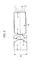
- Fig. 8 illustrates a lens configuration of the illumination optical systems 2a and 2b employed in the endoscope according to the present example.
- lens data of the illumination optical systems 2a according to Example 1 of the present invention are indicated below.
- lens data of the illumination optical system 2b according to Example 1 of the present invention are indicated below.
- ⁇ L 1.7
- a clad of a glass rod 16 was formed by glass having a refractive index of 1.520.
- f L 0.72
- f L1 2.25.
- a light guide fiber 17 that guides illuminating light from a non-illustrated light source to an illumination optical system has a light distribution characteristic that depends on the angle, and thus, this characteristic is indicated below.
- a light distribution characteristic ⁇ ( ⁇ ) of the illumination optical systems 2a and 2b obtained from the characteristic of the light guide fiber is indicated below.
- FIG. 9 A front view of a distal end of an insertion portion of an endoscope according to Example 2 of the present invention is illustrated in Fig. 9 . Also, Fig. 10 illustrates a lens configuration of an observation optical system 1 employed in the endoscope according to the present example.
- ⁇ L 1.7
- a clad of a glass rod 16 was formed by glass having a refractive index of 1.520.
- FIG. 11 A front view of a distal end of an insertion portion of an endoscope according to Example 3 of the present invention is illustrated in Fig. 11 .
- Fig. 12 illustrates a lens configuration of an observation optical system 1 employed in the endoscope according to the present example.
- r 1 3.47
- r 2 3.68
- r 3 3.47
- ⁇ 1 28.4°
- ⁇ 2 155.3°
- ⁇ 3 303.9°
- ⁇ 11.7.
- a lens configuration and lens data of illumination optical systems are the same as those employed in Example 1 described above, and thus description thereof will be omitted.
- Tables 4 and 5 indicate numeral values of conditional expressions (1) to (14) in the configurations of Examples 1 to 3 described above. ⁇ Table 4 ⁇ TABLE. 4 NUMBER EXPRESSION EXAMPLE 1 EXAMPLE 2 EXAMPLE 3 (1) I TC / I TM 0.42 0.30 0.35 (2) I WS / I WC 0.24 0.20 0.21 (4) r I ⁇ 2 / f L f T 13.6 14.7 15.3 (5) r 2 ⁇ 2 / f L f T 13.6 13.6 12.8 (6) F T F FT / f W F FW 0.99 0.96 0.97 (7)
- EXAMPLE 1 EXAMPLE 2
- EXAMPLE 3 NUMBER EXPRESSION 2a 2b 2c 2a 2b (3) f L f T / ⁇ L 1 H 0.48 0.50 0.40 0.50 0.52 (9) f L1 /f L 2.11 3.11 1.80 2.11 3.11 (10) ⁇ (50) / ⁇ (25) 0.25 0.25 0.31 0.25 0.25
Abstract
Description
- The present invention relates to an endoscope including illumination optical systems and an observation optical system.
- Typically, in a distal end portion of an endoscope, structural objects such as an illumination optical system for illuminating a subject, an observation optical system including, at a distal end face thereof, an optical member for receiving incoming light from the subject, a channel that guides a treatment instrument, and a nozzle for cleaning dirt adhering to a lens surface of the image pickup optical system are provided.
- An endoscope including an observation optical system that allows magnified close observation allows not only normal observation but also close observation by moving a part of lenses in the observation optical system and thereby changing a focal length. However, since a same illumination optical system is used for both normal observation and close observation, in particular, in a close observation in which a distance to a subject is no more than 2 mm, a peripheral part of a screen is brighter than a center of the same because of the layout of the illumination optical system. Therefore, when a subject to be focused on is positioned at the center part, a favorable observation cannot be performed because of insufficient distribution of illuminating light.
-
PTL 1 discloses an endoscope that provides only small illumination unevenness in a magnified close observation and thus enables illumination of a subject with sufficient brightness by setting a variable range of a best focal position within a range in which illuminating light beams emitted from a plurality of illumination windows overlap. - Also,
PTL 2 discloses an endoscope that minimizes unevenness in an observation area in close observation by providing illumination means at respective positions on opposite sides of an observation optical system at which an illuminance of a peripheral part of the observation area is no more than twice an illuminance of a center part of the observation area. -
- {PTL 1} Japanese Unexamined Patent Application, Publication No.
2001-346752 - {PTL 2} Japanese Unexamined Patent Application, Publication No.
2000-37345 - However, none of the aforementioned patent literatures takes light distribution in normal observation into consideration, and also has the following problems in close observation.
- In other words, the endoscope disclosed in
PTL 1 requires a best focal position to be set at a distance that provides sufficiently wide distribution of light from the illumination optical systems, making it difficult to bring the endoscope close to a subject, and thus, is not suitable for magnified observation. - The endoscope disclosed in
PTL 2 ensures light distribution by providing a large distance between the observation optical system and the illumination optical systems, resulting in an increase in diameter of a distal end of the endoscope. - The present invention has been made in view of the aforementioned circumstances, and an object of the present invention is to provide an endoscope that ensures sufficient light distribution in both of normal observation and close observation, enabling favorable observation.
- In order to achieve the above object, the present invention provides the following solutions.
- An aspect of the present invention provides an endoscope including: an observation optical system including a plurality of lenses and having a function that allows a magnified observation close to a subject; and a plurality of illumination optical systems each including a plurality of lenses and illuminating the subject with illuminating light, wherein in a close observation in which a distance between a distal end face of the insertion portion and the subject is an arbitrary distance of from 1.5 mm to 2.5 mm, where ITM is a maximum brightness within an observation view field angle and ITC is a center brightness, and in a normal observation in which the distance between the distal end face of the insertion portion and the subject is 50 mm, where IWC is a center brightness and IWS is a brightness at a position of 80% of a maximum view angle, the following conditional expressions are satisfied:


- According to this aspect, upon conditional expression (1) being satisfied, a ratio of a brightness of a center part relative to a peripheral part can be made high also in a magnified close observation, enabling favorable observation. In other words, in a magnified close observation state, a distance between the observation optical system and a subject is smaller than a distance between the observation optical system and each illumination optical system, and thus, the brightness of the peripheral part is larger than that of the center part. In particular, in a magnified close observation, a lesion or the like to be focused on is usually brought to the center part, and thus, favorable observation cannot be performed unless the ratio of the brightness of the center part relative to that of the peripheral part is high. Thus, satisfaction of conditional expression (1) can make the ratio of the brightness of the center part relative to that of the peripheral part high also in magnified close observation, allowing favorable observation.
- In a normal observation state, there is a sufficient distance to a subject, and thus, a brightness of a center part is larger than that of a peripheral part. Also, in this state, a subject having a depth is observed, and an excessive increase in brightness of the peripheral part may hinder favorable observation in the depth direction. On the other hand, an excessive decrease in brightness of the peripheral part may hinder favorable observation of the peripheral part, and thus it is necessary to balance the brightness for observation in the depth direction and the brightness for observation of the peripheral part. Thus, the endoscope is configured so as to satisfy conditional expression (2).
- In order to satisfy both conditional expressions (1) and (2), it is necessary to set the focal length of each illumination optical system so as to conform to a focal length of the observation optical system, and also to satisfy conditional expression (3). As a result of conditional expression (3) being satisfied, the focal length of the observation optical system and the focal length of each illumination optical system are determined, enabling provision of a well-balanced light distribution capability for both of distant observation and close observation.
- Also, in the above aspect, it is preferable that at least two illumination optical systems of the plurality of illumination optical systems satisfy the following conditional expressions:


- Consequently, the distance between the observation optical system and each illumination optical system falls within a desired range, enabling setting of a proper light distribution capability of the illumination optical system.
- Also, in the above aspect, it is preferable that the observation optical system satisfies the following conditional expression:

- Consequently, the view field range can be made to fall within a proper range, enabling provision of even light distribution and thus favorable observation.
- Also, in the above aspect, it is preferable that the observation optical system satisfies the following conditional expression:

- Consequently, a sufficient magnification factor can be provided in a maximum magnification, enabling favorable observation of a subject.
- Also, in the above aspect, it is preferable that the observation optical system satisfies the following conditional expression:

- Consequently, an image pickup device including a sufficient number of pixels can be employed, enabling favorable observation.
- Also, in the above aspect, it is preferable that at least two illumination optical systems of the plurality of illumination optical systems each include three convex lenses and satisfy the following conditional expression:

- Consequently, a proper light distribution range is provided, enabling favorable observation.
- Also, in the above aspect, it is preferable that in at least two illumination optical systems of the plurality of illumination optical systems, where a brightness in a direction toward a center at a distance of 50 mm is 1, a brightness γ (α) at an arbitrary angle α (°) satisfies the following conditional expression:

- Consequently, an amount of variation in an angular direction in a light distribution capability of each illumination optical system is suppressed, enabling maintenance of a proper light distribution capability.
- Also, in the above aspect, it is preferable that at least two illumination optical systems of the plurality of illumination optical systems satisfy the following conditional expressions:


- Consequently, proper arrangement of the observation optical system and the illumination optical systems can be made, enabling suppression of concentration of illuminating light on a subject or light distribution unevenness.
- Also, in the above aspect, it is preferable that three of the illumination optical systems are provided, and the illumination optical systems are illumination optical systems that are identical to one another and each include three convex lenses, and satisfy the following conditional expressions:

- Consequently, proper arrangement of the three illumination optical systems can be made, enabling suppression of concentration of illuminating light on a subject or light distribution unevenness.
- In other words, not only the observation optical system and the illumination optical systems, but also structural objects such as a channel for letting a treatment instrument out and a nozzle for cleaning lenses are arranged. Thus, in particular, where three illumination optical systems are arranged, it may be difficult to arrange all the illumination optical systems symmetrically with reference to an observation optical system. In this case, it is preferable that respective distances of the three illumination optical systems from the observation optical system be made to be equal to one another, and it is preferable that conditional expression (14) be satisfied.
- The present invention provides the effect of ensuring sufficient light distribution and thereby allowing favorable observation in both normal observation and close observation.
-
- {
Fig. 1} Fig. 1 is a schematic configuration diagram illustrating a front face of a distal end of an insertion portion of an endoscope according to an embodiment of the present invention. - {
Fig. 2} Fig. 2 is a schematic configuration diagram illustrating another example of a front face of a distal end of an insertion portion of an endoscope according to an embodiment of the present invention. - {
Fig. 3} Fig. 3 is a diagram illustrating a relationship between an endoscope according to an embodiment of the present invention and a subject in a close observation. - {
Fig. 4} Fig. 4 is a diagram illustrating a relationship between an endoscope according to an embodiment of the present invention and a subject in a normal observation. - {
Fig. 5} Fig. 5 is a diagram illustrating a light distribution characteristic of an illumination optical system employed in an endoscope according to an embodiment of the present invention. - {
Fig. 6} Fig. 6 is a schematic configuration diagram illustrating a front face of a distal end of an insertion portion of an endoscope according to Example 1 of the present invention. - {
Fig. 7} Fig. 7 includes cross-sectional diagrams each illustrating an overall configuration of an observation optical system employed in the endoscope according to Example 1 of the present invention. - {
Fig. 8} Fig. 8 is a cross-sectional diagram illustrating an overall configuration of an illumination optical system employed in the endoscope according to Example 1 of the present invention. - {
Fig. 9} Fig. 9 is a schematic configuration diagram illustrating a front face of a distal end of an insertion portion of an endoscope according to Example 2 of the present invention. - {
Fig. 10} Fig. 10 includes cross-sectional diagrams each illustrating an overall configuration of an observation optical system employed in the endoscope according to Example 2 of the present invention. - {
Fig. 11} Fig. 11 is a schematic configuration diagram illustrating a front face of a distal end of an insertion portion of an endoscope according to Example 3 of the present invention. - {
Fig. 12} Fig. 12 includes cross-sectional diagrams each illustrating an overall configuration of an observation optical system employed in the endoscope according to Example 3 of the present invention. - An endoscope according to an embodiment of the present invention will be described with reference to the drawings.
-
Fig. 1 illustrates a front face of a distal end portion of an insertion portion of an endoscope, and as illustrated inFig. 1 , in the insertion portion, an observationoptical system 1 that picks up an image of an observation target, a plurality of illuminationoptical systems 2 that each distribute illuminating light emitted from a non-illustrated light source and supplied via a light guide fiber, achannel 3 that guides a treatment instrument such as a forceps or a probe, and anozzle 4 that supplies a fluid or air for cleaning to the observationoptical system 1 and the illuminationoptical systems 2. - In
Fig. 1 , each of r1 to r3 is a distance between a center of the observationoptical system 1 and a center of the relevant illuminationoptical system 2. As illustrated inFig. 1 , for an azimuth θ, it is assumed that a direction passing through the center of the observationoptical system 1, which is a rightward direction in the sheet, is θ = 0°, and a counterclockwise direction is a positive direction. For reference, in the example illustrated inFig. 1 , θ1 = 90°, θ2 = 270° and θ3 = 10°. - Also, an insertion diameters ϕ of a distal end of the endoscope is a diameter of the distal end portion of the endoscope. However, a structure of the distal end portion of the endoscope may include a projecting odd-
shape part 20 provided because of a physical structural object in the insertion portion, for example, where a channel cannot be fully accommodated in a round distal end portion. In such case, as illustrated inFig. 2 , a maximum diameter portion is determined as ϕ. - The observation
optical system 1 includes a plurality of lenses and has a function that allows a magnified observation close to a subject. In a magnified close observation state, a distance between the observationoptical system 1 and the subject is smaller than a distance between the observationoptical system 1 and each of the illuminationoptical systems 2, and thus, a brightness of a peripheral part is larger than that of a center part. In particular, in magnified close observation, a lesion to be focused on is usually positioned in the center part, favorable observation is hindered unless a ratio of the brightness of the center part relative to that of the peripheral part is high. - Thus, the endoscope is configured so that in a close observation in which a distance between a distal end face of the insertion portion and the subject is an arbitrary distance of from 1.5 mm to 2.5 mm, where ITM is a maximum brightness within an observation view field angle and ITC is a center brightness, the following conditional expression is satisfied:

- If a value that is below the lower limit of conditional expression (1) is provided, the center part is dark, making it impossible to perform favorable observation when the endoscope is bought close to the subject. On the other hand, if a value exceeding the upper limit is provided, it is possible to perform favorable close observation; however, a distribution of light by each illumination optical system is wide, resulting in deterioration in capability of observation in a depth direction in normal observation.
- Here, it is desirable that conditional expression (1) be satisfied with an arbitrary distance between 1.5 mm and 2.5 mm in depth in magnified close observation, and it is more desirable that conditional expression (1) be satisfied with a distance of no more than 2 mm because more favorable observation can be performed as a synergistic effect in combination with a magnified observation (in which a subject can more closely be observed with magnification).
- In a normal observation state, there is a sufficient distance to a subject, and thus, a brightness of a center part is larger than that of a peripheral part. Also, in this state, a subject having a depth is observed, and an excessive increase in brightness of the peripheral part hinders favorable observation in the depth direction. On the other hand, an excessive decrease in brightness of the peripheral part hinders favorable observation of the peripheral part, and thus, it is necessary to balance the brightness for observation in the depth direction and the brightness for observation of the peripheral part. Therefore, the endoscope is configured so that in a normal observation in which the distance between the distal end face of the insertion portion and the subject is 50 mm, where ICW is a center brightness and IWS is a brightness at a position of 80% of a maximum view angle, the following conditional expression is satisfied:

- If a value that is below the lower limit of conditional expression (2) is provided, the peripheral part is excessively dark in a normal observation and sufficient light distribution cannot be ensured in a close observation. On the other hand, if a value exceeding the upper limit of conditional expression (2) is provided, light distribution in a direction toward a center is insufficient, resulting in insufficiency in brightness in the depth direction in a normal observation, and thus hindering favorable observation.
- In order to satisfy both conditional expressions (1) and (2), it is necessary to set a focal length of each illumination optical system so as to conform to a focal length of the observation optical system, and thus, it is necessary to satisfy the following conditional expression;

- According to the conditional expression, the focal length of the observation optical system and the focal length of each illumination optical system are determined, enabling provision of a well-balanced light distribution capability for both of distant observation and close observation.
- If a value that is below the lower limit of conditional expression (3) is provided, the distribution of light by each illumination optical system is excessively wide, hindering observation in the depth direction in a normal observation or a view field range of the observation optical system is wide, resulting in a failure to provide a desired magnifying power in a close observation.
- If a value exceeding the upper limit of conditional expression (3) is provided, the distribution of light by the illumination optical system is narrow, resulting in insufficiency in center brightness in a close observation and thus hindering the observation, or the view field range of the observation optical system is narrow, which may result in an oversight of a lesion part.
- It is more preferable to employ conditional expression (3)' below instead of conditional expression (3):

- It is even more preferable to employ conditional expression (3)" instead of conditional expression (3) or (3)':

- In order to set a proper light distribution capability of the illumination optical systems, a distance between the observation optical system and each illumination optical system is important. In particular, in close observation, for example, if a distance to a subject is 2 mm, a distance between the observation optical system and the subject is smaller than a distance between the observation optical system and each illumination optical system, which may result in failure of entry of sufficient light. Therefore, it is necessary to satisfy conditional expressions (4) and (5) below:


- If values that are below the respective lower limits of the expressions are provided, the distance between the observation optical system and each of the illumination optical systems is small and thus the observation optical system and each of the illumination optical systems may interfere with each other. If values exceeding the respective upper limits are provided, each of the illumination optical systems is distant from the observation optical system, resulting in failure to maintain a sufficient light distribution capability in close observation, or the focal length of each illumination optical system is small and thus the distribution of light by the illumination optical system is wide, hindering observation in a depth direction in normal observation.
- It is more preferable to employ conditional expressions (4)' and (5)' below instead of conditional expressions (4) and (5) :


- Examples of factors that affect a close observation include a view field range. As the view field range is narrower, the light distribution becomes more even, enabling favorable observation. On the other hand, as the view field range is wider, the light distribution becomes wider, which may cause a difference in brightness between a bright part and a dark part on an observation screen. Thus, the endoscope is preferably configured so as to satisfy conditional expression (6) below:

- If a value that is below the lower limit of conditional expression (6) is provided, wider observation can be performed in close observation, but the center part becomes dark, resulting in failure to perform favorable observation. On the other hand, if a value exceeding the upper limit of conditional expression (6) is provided, as opposed to the above, brightness of the center part can be ensured, but the observation range is limited, resulting in failure to perform wide-range observation.
- It is more preferable to employ conditional expression (6)' below instead of conditional expression (6):

- It is even more preferable to employ conditional expression (6)" instead of conditional expression (6) or (6)':

- In an observation optical system having a magnified observation function, for favorable observation of a subject, it is desirable to provide a sufficient magnification factor in maximum magnification.
- Thus, the endoscope is preferably configured so as to satisfy conditional expression (7) below:

- Conditional expression (7) indicates a magnification factor of a case where a subject having a size of 1 mm passes through the observation optical system, and if a value that is below the lower limit of conditional expression (7) is provided, a sufficient magnifying power cannot be ensured, resulting in failure to perform favorable observation. On the other hand, if a value exceeding the upper limit of conditional expression (7) is provided, a sufficient magnifying power can be ensured, but the optical system becomes a narrow-angle one with a limited observation range, resulting in failure to perform favorable observation.
- Also, in an observation optical system having a magnified observation function, in order to perform favorable observation, an image pickup device desirably has a large number of pixels. Thus, the endoscope is preferably considered so as to satisfy conditional expression (8) below:

- If a value that is below the lower limit of conditional expression (8) is provided, a pixel pitch is large, or an image pickup device is small, and thus, no image pickup device with a large number of pixels is provided. If a value exceeding conditional expression (8) is provided, a large number of pixels is provided, but the pixel pitch is small, and thus, the effect of diffraction is strong, and therefore, if a sufficient magnifying power is provided, the problem of blurring easily occurring, which results in difficulty in focusing, occurs.
- If each illumination optical system includes three convex lenses, a ratio between a focal length of a lens that is farthest on the object side face from among the three convex lenses and a focal length of the entire system has a large impact. Thus, it is preferable to satisfy conditional expression (9) below:

- If a value that is below the lower limit of conditional expression (9) is provided, the light distribution is wide, and thus, favorable observation can be performed in close observation; however, observation in the depth direction is difficult in normal observation. On the other hand, if a value exceeding conditional expression (9) is provided, the light distribution is narrow, and thus, the brightness of a part around a center is insufficient in close observation.
- It is more preferable to employ conditional expression (9)' below instead of conditional expression (9):

- It is even more preferable to employ conditional expression (9)" instead of conditional expression (9) or (9)':

- For balancing close observation and normal observation, in particular, for favorable normal observation, it is necessary to suppress an amount of variation in an angular direction in a light distribution capability of each illumination optical system. A large amount of variation increases the brightness of the part around the center, and on the other hand, a small amount of variation increases the brightness of a part around a periphery. Thus, the endoscope is preferably configured so that in at least two illumination optical systems of the plurality of illumination optical systems, where a brightness in a direction toward a center at a distance of 50 mm is 1, a brightness γ (α) of an arbitrary angle α (°) satisfies conditional expression (10) below:

- If a value that is below the lower limit of conditional expression (10) is provided, in normal observation, the brightness of the part around the center is increased, allowing favorable observation in a depth direction, but no sufficient light is provided to the peripheral part, resulting in deterioration in observation capability. On the other hand, if a value exceeding the upper limit of conditional expression (10) is provided, the brightness of the peripheral part is increased, allowing favorable observation, but the observation capability in the depth direction deteriorates.
- It is more preferable to employ conditional expression (10)' below instead of conditional expression (10):

- In close observation, in particular, the layout of an observation optical system and illumination optical systems has a large impact. If an observation optical system is positioned far from one of two illuminations arranged symmetrically, the side on which the far illumination is dark and brightness concentrates only on one direction on an observation screen, which makes the observation screen appear to have uneven light distribution. Thus, the endoscope is preferably configured so that at least two illumination optical systems of the plurality of illumination optical systems satisfy the following conditional expression:

- If a value that falls outside of the range determined by conditional expression (11) is provided, for example, the problem of uneven light distribution such as only the left side being bright and thus causing deterioration in capability of observation of the right side occurs.
- It is more preferable to employ conditional expression (11)' below instead of conditional expression (11):

- It is even more preferable to employ conditional expression (11)" instead of conditional expression (11) or (11)':

- In the layout, the angular direction also affects the unevenness, and thus, illumination optical systems are favorably installed in directions symmetrical to each other with reference to the image pickup optical system, and a degree of the symmetry is favorably higher. Thus, the endoscope is preferably configured so as to satisfy conditional expression (12) below:

- If a value exceeding a range determined by conditional expression (12) is provided, the problem of light distribution unevenness such as a plurality of parts that are unevenly bright being generated, for example, such as only upper right and upper left parts being illuminated and thus deterioration in capability of observation of the lower side.
- It is more preferable to employ conditional expression (12)' below instead of conditional expression (12):

- It is even more preferable to employ conditional expression (12)" instead of conditional expression (12) or (12)'.

- Furthermore, regarding the layout, typically, a smaller diameter of a distal end of an endoscope is desirable, and thus, the endoscope is preferably configured so that the distance between the image pickup optical system and each of the illumination optical systems and the diameter of the distal end satisfy conditional expression (13) below:

- If a value that is below the lower limit of conditional expression (13) is provided, the diameter of the distal end is large. On the other hand, if a value exceeding the upper limit of conditional expression (13) is provided, the diameter of the distal end can be made small, but limitations on arrangement of, e.g., the observation optical system and the illumination optical systems become tight, causing the problem of a failure to fully accommodate these optical systems within the diameter of the distal end.
- It is more preferable to employ conditional expression (13)' below instead of conditional expression (13):

- It is even more preferable to employ conditional expression (13)" instead of conditional expression (13) or (13)':

- Since an distal end portion of an endoscope includes not only an observation optical system and illumination optical systems, but also structural objects such as a hole, called a channel, for letting a treatment instrument out and a nozzle for cleaning lenses, in particular, where three illumination optical systems are arranged, it may be difficult to arrange all of illumination optical systems symmetrically to one another with reference to an observation optical system. In such case, it is desirable to make distances of the three illumination optical systems from the observation optical system be equal to one another, and the endoscope is preferably configured so as to satisfy conditional expression (14) below:

- As a result of conditional expression (14) being satisfied, the illumination optical systems are equally arranged, enabling suppression of light distribution unevenness and thus illuminating light is illuminated evenly, and thus, the observation capability can be enhanced.
- It is more preferable to employ conditional expression (14)' below instead of conditional expression (14):

- Also, it is even more preferable to employ conditional expression (14)" instead of conditional expression (14) or (14)':

-
Fig. 3 illustrates a configuration in a close observation. A subject 8 is located at a position that is a distance D0 from adistal end face 5 of the endoscope that passes through the centers of the observationoptical system 1 and the illuminationoptical systems 2, and O is a center of anobservation range 7 of the observationoptical system 1, each of P and Q is an extreme periphery. - Also, a
light distribution characteristic 6 of the illuminationoptical systems 2 is provided, ITM is a brightness of a part that is brightest between P and Q, and ITC is a brightness at the center O. A characteristic in close observation lies in that since the distance D0 is from 1.5 mm to 2.5 mm and thus small, thelight distribution characteristic 6 indicates that the brightness of the peripheral part of the observation range is larger than the brightness of the center part of the observation range. - Although
Figs. 1 and3 each indicate a case where an observation optical system and illumination optical systems are located on a same straight line, it should be understood that a maximum brightness and a center brightness in an observation range can also be defined as ITM and ITC, respectively, in a case other than the above case. - Next,
Fig. 4 illustrates a configuration in a normal observation. A subject 10 is located at a position that is a distance of 50 mm away from thedistal end face 5 of the endoscope, and M is a center of aview field range 11 of the observation optical system, and each of L and N is a position that is 80% of a maximum view angle. Also, a light distribution characteristic 9 of the illumination optical systems is provided, and IWS is a brightness at each of L and N and ICW is a brightness at the center part M. A characteristic of normal observation lies in that when the distance of 50 mm is reached, the light distribution characteristic 9 indicates that the impact of the layout of the illumination optical systems is small and exhibits a shape that is substantially even with reference to the center. -
Fig. 5 illustrates a light distribution characteristic of one illumination optical system. - A
light distribution 13 to a subject 10 that is a distance of 50 mm away from an illuminationoptical system 2 is provided. Here, where the upper side in the sheet ofFig. 5 is 0°, a brightness at a position of 0° is defined as γ(0) = 1, and a brightness at a position that is an angle α away from the position of 0° in a clockwise direction is defined as γ (α). Since the light distribution exhibits symmetry, and thus, the position may be a position that is an angle α away from the position of 0° in a counterclockwise direction. - As described above, the present embodiment enables a ratio of a brightness of a center part relative to that of a peripheral part not only in normal observation but also in magnified close observation, ensuring sufficient light distribution and thus allowing favorable observation in both normal observation and close observation.
- Next, Examples 1 to 3 of the endoscope according to the present embodiment described above will be described with reference to
Figs. 6 to 12 . In lens data indicated in each example, r is a curvature radius (unit: mm), d is a surface spacing (mm), Nd is a refractive index for a d line, and Vd is an Abbe number for a d line. - A front view of a distal end of an insertion portion of an endoscope according to Example 1 of the present invention is illustrated in
Fig. 6 . In Example 1, a total of three illumination optical systems, which are two identical illuminationoptical systems 2a and an illuminationoptical system 2b, are employed. - In the present example, r1 = 3.2, r2 = 3.2, r3 = 5.16, θ1 = 90°, θ2 = 270°, θ3 = 8.9° and ϕ = 9.9.
-
Fig. 7 illustrates a lens configuration of an observationoptical system 1 employed in the endoscope according to the present example, andFig. 8 illustrates a lens configuration of the illuminationoptical systems - Lens data of the observation optical system according to Example 1 of the present invention are indicated below.
-
Surfacenumber r d Nd Vd Objectsurface ∞ d0 1 ∞ 0.40 1.883 40.76 2 1.11 0.63 3 ∞ 0.40 1.521 65.13 4 ∞ 0.30 5 -4.49 1.56 1.517 52.43 6 -2.21 0.06 7 ∞ 0.97 1.750 35.33 8 -1.56 0.36 1.923 18.9 9 -2.70 0.03 10 (Diaphragm) ∞ d10 11 ∞ 0.40 1.697 55.53 12 1.58 0.71 1.581 40.75 13 7.99 d13 14 8. 97 1.00 1.591 61.14 15 -2.98 0.05 16 4.00 1.30 1. 488 70.23 17 -2.68 0.30 1.923 18.9 18 ∞ 0.06 19 ∞ 0.36 1.523 58.5 20 ∞ 0.94 21 ∞ 0.84 1.516 64.14 22 ∞ 0.66 1.505 63.26 23 (Imageplane) ∞ -
Normalobservation Maximummagnification d0 50 2 d10 0.3 1.9 d13 1.9 0.3 Focallength 1.24 1.40 Front-sidefocalposition 0.97 0.85 Maximumimageheight 1.2 1.2 Paraxialmagnifyingpower - -0.49 Pixelpitch 0.0042 0.0042 - Next, lens data of the illumination
optical systems 2a according to Example 1 of the present invention are indicated below. - Here, (ϕL = 1.3, and a clad of a
glass rod 16 was formed by glass having a refractive index of 1.520. In this case, fL = 0.54 and fL1 = 1.14. -
Surfacenumber r d Nd 1 ∞ 1.11 1.883 2 -1.01 0.04 3 1.20 0.65 1.883 4 ∞ 0 5 1.26 2.75 1.805 6 ∞ - Next, lens data of the illumination
optical system 2b according to Example 1 of the present invention are indicated below. - Here, ϕL = 1.7, and a clad of a
glass rod 16 was formed by glass having a refractive index of 1.520. In this case, fL = 0.72 and fL1 = 2.25. -
Surfacenumber r d Nd 1 ∞ 1.30 1.883 2 -2.00 0.04 3 2.00 0.75 1.883 4 -2.00 0.05 5 1.91 2.90 1.730 6 ∞ - Also, a
light guide fiber 17 that guides illuminating light from a non-illustrated light source to an illumination optical system has a light distribution characteristic that depends on the angle, and thus, this characteristic is indicated below. - {Table 1}
TABLE. 1 ANGLE α ILLUMINANCE γ (α) 0 1.00 5 0.97 10 0.94 15 0.85 20 0.67 25 0.46 30 0.27 35 0.13 40 0.05 45 0.01 50 0.00 55 0.00 60 0.00 65 0.00 70 0.00 75 0.00 - A light distribution characteristic γ(α) of the illumination
optical systems
{Table 2}TABLE. 2 2a 2b ANGLE α ILLUMINANCE γ (α) ILLUMINANCE γ (α) 0 1.00 1.00 5 0.99 0.98 10 0.95 0.94 15 0.88 0.87 20 0.80 0.77 25 0.70 0.67 30 0.61 0.56 35 0.50 0.45 40 0.38 0.35 45 0.27 0.25 50 0.18 0.17 55 0.10 0.10 60 0.05 0.05 65 0.02 0.02 70 0.01 0.01 75 0.00 0.00 - A front view of a distal end of an insertion portion of an endoscope according to Example 2 of the present invention is illustrated in
Fig. 9 . Also,Fig. 10 illustrates a lens configuration of an observationoptical system 1 employed in the endoscope according to the present example. - In the present example, r1 = 3.99, r2 = 3.84, r3 = 3.80, θ1 = 28.2°, θ2 = 157.9°, θ3 = 294.6° and ϕ = 13.2.
- Lens data of the observation optical system according to Example 2 of the present invention are indicated below.
-
Surfacenumber r d Nd Vd Objectsurface ∞ d0 1 ∞ 0.48 1.883 40.76 21.39 0.80 3 ∞ 0.40 1.521 65.13 4 ∞ 0.42 5 -2.22 1.41 1.750 35.33 6 -2.54 0.03 7 4.56 1.07 1.773 49.6 8 -2.42 0.37 1.923 18.9 9 -4.67 0.29 10 (Diaphragm) ∞ d10 11 ∞ 0.40 1.488 70.23 12 1.63 0.40 1.593 35.31 13 2.10 d13 14 4.51 1.33 1. 488 70.23 15 -3.30 0.05 16 6.34 1.92 1.488 70.23 17 -2.19 0.48 1.923 18.9 18 -6.59 0.03 19 ∞ 0.40 1.523 58.5 20 ∞ 0.63 21 ∞ 0.90 1.516 64.14 22 ∞ 0.60 1.505 63.26 23 (Imageplane) ∞ -
Normalobservation Maximummagnification d0 50 2.2 d10 0.29 1.7 d13 1.87 0.46 Focallength 1.49 1.72 Front-sidefocalposition 1.14 0.95 Maximumimageheight 1.6 1.6 Paraxialmagnifyingpower - -0.55 Pixelpitch 0.0034 0.0034 - Since the lens configuration of the illumination optical systems is the same as that employed in Example 1, and thus illustration of the lens configuration is omitted, and the lens data are indicated alone. Here, ϕL = 1.7, and a clad of a
glass rod 16 was formed by glass having a refractive index of 1.520. In this case, fL = 0.63 and fL1 = 1.13. -
Surfacenumber r d Nd 1 ∞ 1.35 1.883 2 -1.01 0.06 3 2.58 0.59 1.883 4 -2.58 0.06 5 1.90 2.90 1.730 6 ∞ - A light guide fiber that is the same as the light guide fiber employed in Example 1 described above was employed, and a light distribution characteristic γ(α) of illumination
optical system 2c obtained by the characteristic of the light guide fiber is indicated below.
{Table 3}TABLE. 3 2c ANGLE α ILLUMINANCE γ (α) 0 1.00 5 0.98 10 0.95 15 0.89 20 0.82 25 0.73 30 0.63 35 0.53 40 0.42 45 0.32 50 0.22 55 0.14 60 0.08 65 0.04 70 0.02 75 0.00 - A front view of a distal end of an insertion portion of an endoscope according to Example 3 of the present invention is illustrated in
Fig. 11 . Also,Fig. 12 illustrates a lens configuration of an observationoptical system 1 employed in the endoscope according to the present example. - In the present example, r1 = 3.47, r2 = 3.68, r3 = 3.47, θ1 = 28.4°, θ2 = 155.3°, θ3 = 303.9° and ϕ = 11.7.
- Lens data of an observation optical system according to Example 3 of the present invention are indicated below.
-
Surfacenumber r d Nd Vd Objectsurface ∞ d0 1 ∞ 0.36 1.883 40.76 2 1.19 0.75 3 ∞ 0.40 1.521 65.13 4 ∞ 0.37 5 -3.55 1.78 1.581 40.75 6 -2.38 0.30 7 6.83 0.83 1.517 52.43 8 -1.38 0.30 1.923 18.9 9 -2.14 0.05 10 (Diaphragm) ∞ d10 11 ∞ 0.31 1.773 49.6 12 1.42 0.58 1.728 29.46 13 3.67 d13 14 4.68 1.20 1.816 46.62 15 -6.02 0.03 16 4.91 1.60 1.618 63.33 17 -2.42 0.36 1.923 18.9 18 11.2 0.16 19 ∞ 0.40 1.523 58.5 20 ∞ 0.83 21 ∞ 0.80 1.516 64.14 22 ∞ 0.70 1.505 63.26 23 (Imageplane) ∞ -
Normalobservation Maximummagnification d0 50 2.5 d10 0.32 1.78 d13 1.9 0.44 Focallength 1.19 1.46 Front-sidefocalposition 0.99 0.78 Maximumimageheight 1.2 1.2 Paraxialmagnifyingpower - -0.45 Pixelpitch 0.0028 0.0028 - A lens configuration and lens data of illumination optical systems are the same as those employed in Example 1 described above, and thus description thereof will be omitted.
- Tables 4 and 5 indicate numeral values of conditional expressions (1) to (14) in the configurations of Examples 1 to 3 described above.
{Table 4}TABLE. 4 NUMBER EXPRESSION EXAMPLE 1 EXAMPLE 2 EXAMPLE 3 (1) ITC / ITM 0.42 0.30 0.35 (2) IWS / IWC 0.24 0.20 0.21 (4) rI^2 / fLfT 13.6 14.7 15.3 (5) r2^2 / fLfT 13.6 13.6 12.8 (6) FTFFT / fWFFW 0.99 0.96 0.97 (7) |1×β / IH| 0.41 0.34 0.37 (8) IH/ (1000P) 0.29 0.47 0.43 (11) r1 / r2 1.00 1.04 0.94 (12) |θ1 - θ2| 180 130 127 (13) r1r2 / φ^2 0.10 0.09 0.09 (14) min(r1, r2, r3) / Max(r1, r2, r3) - 0.95 - TABLE. 5 EXAMPLE 1 EXAMPLE 2 EXAMPLE 3 NUMBER EXPRESSION 2a 2b 2c 2a 2b (3) fLfT/φL1H 0.48 0.50 0.40 0.50 0.52 (9) fL1/fL 2.11 3.11 1.80 2.11 3.11 (10) γ(50) / γ (25) 0.25 0.25 0.31 0.25 0.25 -
- 1
- observation optical system
- 2
- illumination optical system
- 3
- channel
- 4
- nozzle
Claims (9)
- An endoscope comprising:an observation optical system provided in a distal end of an insertion portion, the observation optical system including a plurality of lenses and having a function that allows a magnified observation close to a subject; anda plurality of illumination optical systems provided in the distal end of the insertion portion, the plurality of illumination optical systems each including a plurality of lenses and illuminating the subject with illuminating light,wherein in a close observation in which a distance between a distal end face of the insertion portion and the subject is an arbitrary distance of from 1.5 mm to 2.5 mm, where ITM is a maximum brightness within an observation view field angle and ITC is a center brightness, andin a normal observation in which the distance between the distal end face of the insertion portion and the subject is 50 mm, where IWC is a center brightness and IWS is a brightness at a position of 80% of a maximum view angle, the following conditional expressions are satisfied:


- The endoscope according to claim 1, wherein at least two illumination optical systems of the plurality of illumination optical systems satisfy the following conditional expressions:


- The endoscope according to claim 1 or 2, wherein the observation optical system satisfies the following conditional expression:

- The endoscope according to claim 3, wherein the observation optical system satisfies the following conditional expression:

- The endoscope according to claim 3, wherein the observation optical system satisfies the following conditional expression:

- The endoscope according to claim 2, wherein at least two illumination optical systems of the plurality of illumination optical systems each include three convex lenses and satisfy the following conditional expression:

- The endoscope according to claim 2, wherein in at least two illumination optical systems of the plurality of illumination optical systems, where a brightness in a direction toward a center at a distance of 50 mm is 1, a brightness γ (α) at an arbitrary angle α (°) satisfies the following conditional expression:

- The endoscope according to claim 2, wherein at least two illumination optical systems of the plurality of illumination optical systems satisfy the following conditional expressions:


- The endoscope according to claim 1, wherein three of the illumination optical systems are provided, and the illumination optical systems are illumination optical systems that are identical to one another and each include three convex lenses, and satisfy the following conditional expression:

Applications Claiming Priority (2)
| Application Number | Priority Date | Filing Date | Title |
|---|---|---|---|
| JP2013108141 | 2013-05-22 | ||
| PCT/JP2014/063513 WO2014189091A1 (en) | 2013-05-22 | 2014-05-21 | Endoscope |
Publications (3)
| Publication Number | Publication Date |
|---|---|
| EP3000378A1 true EP3000378A1 (en) | 2016-03-30 |
| EP3000378A4 EP3000378A4 (en) | 2017-01-25 |
| EP3000378B1 EP3000378B1 (en) | 2017-11-22 |
Family
ID=51933643
Family Applications (1)
| Application Number | Title | Priority Date | Filing Date |
|---|---|---|---|
| EP14800911.1A Active EP3000378B1 (en) | 2013-05-22 | 2014-05-21 | Endoscope |
Country Status (5)
| Country | Link |
|---|---|
| US (1) | US9808141B2 (en) |
| EP (1) | EP3000378B1 (en) |
| JP (1) | JP5711436B1 (en) |
| CN (1) | CN104883953B (en) |
| WO (1) | WO2014189091A1 (en) |
Families Citing this family (7)
| Publication number | Priority date | Publication date | Assignee | Title |
|---|---|---|---|---|
| WO2015107844A1 (en) * | 2014-01-15 | 2015-07-23 | オリンパス株式会社 | Endoscope device |
| CN106102546B (en) * | 2014-04-10 | 2018-05-04 | 奥林巴斯株式会社 | Endoscope |
| WO2016027634A1 (en) * | 2014-08-22 | 2016-02-25 | オリンパス株式会社 | Endscope device |
| CN106455915B (en) * | 2014-10-06 | 2018-06-12 | 奥林巴斯株式会社 | Endoscope |
| WO2017068916A1 (en) * | 2015-10-20 | 2017-04-27 | オリンパス株式会社 | Endoscope |
| WO2017130524A1 (en) * | 2016-01-29 | 2017-08-03 | オリンパス株式会社 | Endoscope |
| WO2018154693A1 (en) * | 2017-02-23 | 2018-08-30 | オリンパス株式会社 | Endoscope |
Citations (5)
| Publication number | Priority date | Publication date | Assignee | Title |
|---|---|---|---|---|
| GB2011111A (en) * | 1977-12-27 | 1979-07-04 | Fuji Photo Optical Co Ltd | Illumination optical system using optical fibre bundles |
| JPH10239740A (en) * | 1997-02-28 | 1998-09-11 | Toshiba Corp | Endoscope device |
| JP2001346752A (en) * | 2000-06-09 | 2001-12-18 | Asahi Optical Co Ltd | Endoscope for proximity magnifying observation |
| JP2003235789A (en) * | 2003-01-14 | 2003-08-26 | Fuji Photo Optical Co Ltd | Observing instrument for endoscope |
| US20120147165A1 (en) * | 2010-12-13 | 2012-06-14 | Olympus Corporation | Control device, endoscope apparatus, and focus control method |
Family Cites Families (25)
| Publication number | Priority date | Publication date | Assignee | Title |
|---|---|---|---|---|
| JPS5620428A (en) * | 1979-07-27 | 1981-02-26 | Olympus Optical Co | Lighting optical system for endoscope |
| JPS60203910A (en) * | 1984-03-28 | 1985-10-15 | Olympus Optical Co Ltd | Objective lens of high power for endoscope |
| JPH0658458B2 (en) * | 1985-07-12 | 1994-08-03 | オリンパス光学工業株式会社 | Endoscope device |
| JPH01128031A (en) * | 1987-11-13 | 1989-05-19 | Olympus Optical Co Ltd | Image pickup optical system |
| JP2921681B2 (en) * | 1989-05-17 | 1999-07-19 | オリンパス光学工業株式会社 | Endoscope |
| US5861987A (en) * | 1994-08-30 | 1999-01-19 | Olympus Optical Co., Ltd. | Stereoscopic-vision endoscope offering a large angle of introversion and a necessary and sufficient sense of three-dimensionality |
| JPH11119117A (en) * | 1997-10-20 | 1999-04-30 | Olympus Optical Co Ltd | Endoscope illuminating system |
| US5980454A (en) * | 1997-12-01 | 1999-11-09 | Endonetics, Inc. | Endoscopic imaging system employing diffractive optical elements |
| US6252723B1 (en) * | 1998-03-03 | 2001-06-26 | Olympus Optical Co., Ltd. | Objective optical system |
| JP3363377B2 (en) * | 1998-04-30 | 2003-01-08 | オリンパス光学工業株式会社 | Electronic endoscope |
| JP3661487B2 (en) | 1998-05-18 | 2005-06-15 | フジノン株式会社 | Endoscope observation device |
| IL135571A0 (en) * | 2000-04-10 | 2001-05-20 | Doron Adler | Minimal invasive surgery imaging system |
| JP2003037345A (en) * | 2001-07-25 | 2003-02-07 | Sanyo Electric Co Ltd | Circuit device and its manufacturing method |
| JP4012384B2 (en) | 2001-09-28 | 2007-11-21 | フジノン株式会社 | Electronic endoscope apparatus with optical zoom mechanism |
| JP4128505B2 (en) * | 2003-09-05 | 2008-07-30 | オリンパス株式会社 | Capsule endoscope |
| JP4377745B2 (en) * | 2004-05-14 | 2009-12-02 | オリンパス株式会社 | Electronic endoscope |
| JP4727959B2 (en) * | 2004-09-03 | 2011-07-20 | オリンパス株式会社 | Endoscope optical system |
| US7215478B1 (en) * | 2006-03-06 | 2007-05-08 | Olympus Corporation | Immersion objective optical system |
| JP4728162B2 (en) * | 2006-04-21 | 2011-07-20 | オリンパスメディカルシステムズ株式会社 | Endoscope system |
| JP4920572B2 (en) * | 2007-12-21 | 2012-04-18 | オリンパスメディカルシステムズ株式会社 | Endoscope objective lens |
| JP2010081957A (en) * | 2008-09-29 | 2010-04-15 | Olympus Corp | Light source device |
| CN102209926B (en) * | 2008-11-11 | 2013-05-29 | 奥林巴斯医疗株式会社 | Lighting optical system for endoscope |
| JP2012135432A (en) * | 2010-12-27 | 2012-07-19 | Fujifilm Corp | Endoscope |
| CN103460111B (en) * | 2011-12-01 | 2016-12-14 | 奥林巴斯株式会社 | Endoscope apparatus |
| EP2899580B1 (en) * | 2012-09-18 | 2018-04-11 | Olympus Corporation | Endoscope objective lens |
-
2014
- 2014-05-21 JP JP2014551433A patent/JP5711436B1/en active Active
- 2014-05-21 EP EP14800911.1A patent/EP3000378B1/en active Active
- 2014-05-21 WO PCT/JP2014/063513 patent/WO2014189091A1/en active Application Filing
- 2014-05-21 CN CN201480003908.6A patent/CN104883953B/en active Active
-
2015
- 2015-05-28 US US14/724,177 patent/US9808141B2/en active Active
Patent Citations (5)
| Publication number | Priority date | Publication date | Assignee | Title |
|---|---|---|---|---|
| GB2011111A (en) * | 1977-12-27 | 1979-07-04 | Fuji Photo Optical Co Ltd | Illumination optical system using optical fibre bundles |
| JPH10239740A (en) * | 1997-02-28 | 1998-09-11 | Toshiba Corp | Endoscope device |
| JP2001346752A (en) * | 2000-06-09 | 2001-12-18 | Asahi Optical Co Ltd | Endoscope for proximity magnifying observation |
| JP2003235789A (en) * | 2003-01-14 | 2003-08-26 | Fuji Photo Optical Co Ltd | Observing instrument for endoscope |
| US20120147165A1 (en) * | 2010-12-13 | 2012-06-14 | Olympus Corporation | Control device, endoscope apparatus, and focus control method |
Non-Patent Citations (2)
| Title |
|---|
| None * |
| See also references of WO2014189091A1 * |
Also Published As
| Publication number | Publication date |
|---|---|
| WO2014189091A1 (en) | 2014-11-27 |
| JPWO2014189091A1 (en) | 2017-02-23 |
| EP3000378A4 (en) | 2017-01-25 |
| US20150257630A1 (en) | 2015-09-17 |
| CN104883953B (en) | 2016-08-24 |
| JP5711436B1 (en) | 2015-04-30 |
| US9808141B2 (en) | 2017-11-07 |
| CN104883953A (en) | 2015-09-02 |
| EP3000378B1 (en) | 2017-11-22 |
Similar Documents
| Publication | Publication Date | Title |
|---|---|---|
| EP3000378B1 (en) | Endoscope | |
| EP2749929B1 (en) | Eyepiece lens system and image observation device | |
| EP2787383A1 (en) | Endoscope device | |
| US10130245B2 (en) | Endoscope apparatus | |
| EP3015895A1 (en) | Endoscope objective optical system | |
| CN107003502B (en) | Endoscope objective optical system | |
| WO2014054407A1 (en) | Endoscope objective optical system | |
| US9851551B2 (en) | Endoscope with plurality of illumination optical systems | |
| JP5942063B1 (en) | Endoscope device | |
| US10786144B2 (en) | Endoscope | |
| US10441148B2 (en) | Illumination lens and illumination optical system for an endoscope | |
| US20170367568A1 (en) | Endoscope | |
| WO2013035522A1 (en) | Endoscope |
Legal Events
| Date | Code | Title | Description |
|---|---|---|---|
| PUAI | Public reference made under article 153(3) epc to a published international application that has entered the european phase |
Free format text: ORIGINAL CODE: 0009012 |
|
| 17P | Request for examination filed |
Effective date: 20151203 |
|
| AK | Designated contracting states |
Kind code of ref document: A1 Designated state(s): AL AT BE BG CH CY CZ DE DK EE ES FI FR GB GR HR HU IE IS IT LI LT LU LV MC MK MT NL NO PL PT RO RS SE SI SK SM TR |
|
| AX | Request for extension of the european patent |
Extension state: BA ME |
|
| DAX | Request for extension of the european patent (deleted) | ||
| RAP1 | Party data changed (applicant data changed or rights of an application transferred) |
Owner name: OLYMPUS CORPORATION |
|
| RAP1 | Party data changed (applicant data changed or rights of an application transferred) |
Owner name: OLYMPUS CORPORATION |
|
| RIN1 | Information on inventor provided before grant (corrected) |
Inventor name: SONE, NOBUHIKO Inventor name: TAKATO, HIDEYASU |
|
| A4 | Supplementary search report drawn up and despatched |
Effective date: 20161222 |
|
| RIC1 | Information provided on ipc code assigned before grant |
Ipc: G02B 23/26 20060101ALI20161216BHEP Ipc: A61B 1/00 20060101AFI20161216BHEP |
|
| GRAP | Despatch of communication of intention to grant a patent |
Free format text: ORIGINAL CODE: EPIDOSNIGR1 |
|
| STAA | Information on the status of an ep patent application or granted ep patent |
Free format text: STATUS: GRANT OF PATENT IS INTENDED |
|
| INTG | Intention to grant announced |
Effective date: 20170620 |
|
| GRAS | Grant fee paid |
Free format text: ORIGINAL CODE: EPIDOSNIGR3 |
|
| GRAA | (expected) grant |
Free format text: ORIGINAL CODE: 0009210 |
|
| STAA | Information on the status of an ep patent application or granted ep patent |
Free format text: STATUS: THE PATENT HAS BEEN GRANTED |
|
| AK | Designated contracting states |
Kind code of ref document: B1 Designated state(s): AL AT BE BG CH CY CZ DE DK EE ES FI FR GB GR HR HU IE IS IT LI LT LU LV MC MK MT NL NO PL PT RO RS SE SI SK SM TR |
|
| REG | Reference to a national code |
Ref country code: GB Ref legal event code: FG4D |
|
| REG | Reference to a national code |
Ref country code: CH Ref legal event code: EP |
|
| REG | Reference to a national code |
Ref country code: IE Ref legal event code: FG4D |
|
| REG | Reference to a national code |
Ref country code: AT Ref legal event code: REF Ref document number: 947603 Country of ref document: AT Kind code of ref document: T Effective date: 20171215 |
|
| REG | Reference to a national code |
Ref country code: DE Ref legal event code: R096 Ref document number: 602014017710 Country of ref document: DE |
|
| REG | Reference to a national code |
Ref country code: NL Ref legal event code: MP Effective date: 20171122 |
|
| REG | Reference to a national code |
Ref country code: LT Ref legal event code: MG4D |
|
| REG | Reference to a national code |
Ref country code: AT Ref legal event code: MK05 Ref document number: 947603 Country of ref document: AT Kind code of ref document: T Effective date: 20171122 |
|
| PG25 | Lapsed in a contracting state [announced via postgrant information from national office to epo] |
Ref country code: NO Free format text: LAPSE BECAUSE OF FAILURE TO SUBMIT A TRANSLATION OF THE DESCRIPTION OR TO PAY THE FEE WITHIN THE PRESCRIBED TIME-LIMIT Effective date: 20180222 Ref country code: FI Free format text: LAPSE BECAUSE OF FAILURE TO SUBMIT A TRANSLATION OF THE DESCRIPTION OR TO PAY THE FEE WITHIN THE PRESCRIBED TIME-LIMIT Effective date: 20171122 Ref country code: NL Free format text: LAPSE BECAUSE OF FAILURE TO SUBMIT A TRANSLATION OF THE DESCRIPTION OR TO PAY THE FEE WITHIN THE PRESCRIBED TIME-LIMIT Effective date: 20171122 Ref country code: LT Free format text: LAPSE BECAUSE OF FAILURE TO SUBMIT A TRANSLATION OF THE DESCRIPTION OR TO PAY THE FEE WITHIN THE PRESCRIBED TIME-LIMIT Effective date: 20171122 Ref country code: SE Free format text: LAPSE BECAUSE OF FAILURE TO SUBMIT A TRANSLATION OF THE DESCRIPTION OR TO PAY THE FEE WITHIN THE PRESCRIBED TIME-LIMIT Effective date: 20171122 |
|
| PG25 | Lapsed in a contracting state [announced via postgrant information from national office to epo] |
Ref country code: RS Free format text: LAPSE BECAUSE OF FAILURE TO SUBMIT A TRANSLATION OF THE DESCRIPTION OR TO PAY THE FEE WITHIN THE PRESCRIBED TIME-LIMIT Effective date: 20171122 Ref country code: HR Free format text: LAPSE BECAUSE OF FAILURE TO SUBMIT A TRANSLATION OF THE DESCRIPTION OR TO PAY THE FEE WITHIN THE PRESCRIBED TIME-LIMIT Effective date: 20171122 Ref country code: AT Free format text: LAPSE BECAUSE OF FAILURE TO SUBMIT A TRANSLATION OF THE DESCRIPTION OR TO PAY THE FEE WITHIN THE PRESCRIBED TIME-LIMIT Effective date: 20171122 Ref country code: LV Free format text: LAPSE BECAUSE OF FAILURE TO SUBMIT A TRANSLATION OF THE DESCRIPTION OR TO PAY THE FEE WITHIN THE PRESCRIBED TIME-LIMIT Effective date: 20171122 Ref country code: BG Free format text: LAPSE BECAUSE OF FAILURE TO SUBMIT A TRANSLATION OF THE DESCRIPTION OR TO PAY THE FEE WITHIN THE PRESCRIBED TIME-LIMIT Effective date: 20180222 Ref country code: GR Free format text: LAPSE BECAUSE OF FAILURE TO SUBMIT A TRANSLATION OF THE DESCRIPTION OR TO PAY THE FEE WITHIN THE PRESCRIBED TIME-LIMIT Effective date: 20180223 |
|
| PG25 | Lapsed in a contracting state [announced via postgrant information from national office to epo] |
Ref country code: CZ Free format text: LAPSE BECAUSE OF FAILURE TO SUBMIT A TRANSLATION OF THE DESCRIPTION OR TO PAY THE FEE WITHIN THE PRESCRIBED TIME-LIMIT Effective date: 20171122 Ref country code: CY Free format text: LAPSE BECAUSE OF FAILURE TO SUBMIT A TRANSLATION OF THE DESCRIPTION OR TO PAY THE FEE WITHIN THE PRESCRIBED TIME-LIMIT Effective date: 20171122 Ref country code: EE Free format text: LAPSE BECAUSE OF FAILURE TO SUBMIT A TRANSLATION OF THE DESCRIPTION OR TO PAY THE FEE WITHIN THE PRESCRIBED TIME-LIMIT Effective date: 20171122 Ref country code: DK Free format text: LAPSE BECAUSE OF FAILURE TO SUBMIT A TRANSLATION OF THE DESCRIPTION OR TO PAY THE FEE WITHIN THE PRESCRIBED TIME-LIMIT Effective date: 20171122 Ref country code: SK Free format text: LAPSE BECAUSE OF FAILURE TO SUBMIT A TRANSLATION OF THE DESCRIPTION OR TO PAY THE FEE WITHIN THE PRESCRIBED TIME-LIMIT Effective date: 20171122 |
|
| REG | Reference to a national code |
Ref country code: DE Ref legal event code: R097 Ref document number: 602014017710 Country of ref document: DE |
|
| PG25 | Lapsed in a contracting state [announced via postgrant information from national office to epo] |
Ref country code: RO Free format text: LAPSE BECAUSE OF FAILURE TO SUBMIT A TRANSLATION OF THE DESCRIPTION OR TO PAY THE FEE WITHIN THE PRESCRIBED TIME-LIMIT Effective date: 20171122 Ref country code: IT Free format text: LAPSE BECAUSE OF FAILURE TO SUBMIT A TRANSLATION OF THE DESCRIPTION OR TO PAY THE FEE WITHIN THE PRESCRIBED TIME-LIMIT Effective date: 20171122 Ref country code: SM Free format text: LAPSE BECAUSE OF FAILURE TO SUBMIT A TRANSLATION OF THE DESCRIPTION OR TO PAY THE FEE WITHIN THE PRESCRIBED TIME-LIMIT Effective date: 20171122 Ref country code: PL Free format text: LAPSE BECAUSE OF FAILURE TO SUBMIT A TRANSLATION OF THE DESCRIPTION OR TO PAY THE FEE WITHIN THE PRESCRIBED TIME-LIMIT Effective date: 20171122 |
|
| PLBE | No opposition filed within time limit |
Free format text: ORIGINAL CODE: 0009261 |
|
| STAA | Information on the status of an ep patent application or granted ep patent |
Free format text: STATUS: NO OPPOSITION FILED WITHIN TIME LIMIT |
|
| 26N | No opposition filed |
Effective date: 20180823 |
|
| PG25 | Lapsed in a contracting state [announced via postgrant information from national office to epo] |
Ref country code: SI Free format text: LAPSE BECAUSE OF FAILURE TO SUBMIT A TRANSLATION OF THE DESCRIPTION OR TO PAY THE FEE WITHIN THE PRESCRIBED TIME-LIMIT Effective date: 20171122 |
|
| REG | Reference to a national code |
Ref country code: CH Ref legal event code: PL |
|
| GBPC | Gb: european patent ceased through non-payment of renewal fee |
Effective date: 20180521 |
|
| REG | Reference to a national code |
Ref country code: BE Ref legal event code: MM Effective date: 20180531 |
|
| PG25 | Lapsed in a contracting state [announced via postgrant information from national office to epo] |
Ref country code: MC Free format text: LAPSE BECAUSE OF FAILURE TO SUBMIT A TRANSLATION OF THE DESCRIPTION OR TO PAY THE FEE WITHIN THE PRESCRIBED TIME-LIMIT Effective date: 20171122 |
|
| REG | Reference to a national code |
Ref country code: IE Ref legal event code: MM4A |
|
| PG25 | Lapsed in a contracting state [announced via postgrant information from national office to epo] |
Ref country code: LI Free format text: LAPSE BECAUSE OF NON-PAYMENT OF DUE FEES Effective date: 20180531 Ref country code: CH Free format text: LAPSE BECAUSE OF NON-PAYMENT OF DUE FEES Effective date: 20180531 |
|
| PG25 | Lapsed in a contracting state [announced via postgrant information from national office to epo] |
Ref country code: LU Free format text: LAPSE BECAUSE OF NON-PAYMENT OF DUE FEES Effective date: 20180521 |
|
| PG25 | Lapsed in a contracting state [announced via postgrant information from national office to epo] |
Ref country code: GB Free format text: LAPSE BECAUSE OF NON-PAYMENT OF DUE FEES Effective date: 20180521 Ref country code: FR Free format text: LAPSE BECAUSE OF NON-PAYMENT OF DUE FEES Effective date: 20180531 Ref country code: IE Free format text: LAPSE BECAUSE OF NON-PAYMENT OF DUE FEES Effective date: 20180521 |
|
| PG25 | Lapsed in a contracting state [announced via postgrant information from national office to epo] |
Ref country code: BE Free format text: LAPSE BECAUSE OF NON-PAYMENT OF DUE FEES Effective date: 20180531 |
|
| PG25 | Lapsed in a contracting state [announced via postgrant information from national office to epo] |
Ref country code: ES Free format text: LAPSE BECAUSE OF FAILURE TO SUBMIT A TRANSLATION OF THE DESCRIPTION OR TO PAY THE FEE WITHIN THE PRESCRIBED TIME-LIMIT Effective date: 20171122 |
|
| PG25 | Lapsed in a contracting state [announced via postgrant information from national office to epo] |
Ref country code: MT Free format text: LAPSE BECAUSE OF NON-PAYMENT OF DUE FEES Effective date: 20180521 |
|
| PG25 | Lapsed in a contracting state [announced via postgrant information from national office to epo] |
Ref country code: TR Free format text: LAPSE BECAUSE OF FAILURE TO SUBMIT A TRANSLATION OF THE DESCRIPTION OR TO PAY THE FEE WITHIN THE PRESCRIBED TIME-LIMIT Effective date: 20171122 |
|
| PG25 | Lapsed in a contracting state [announced via postgrant information from national office to epo] |
Ref country code: PT Free format text: LAPSE BECAUSE OF FAILURE TO SUBMIT A TRANSLATION OF THE DESCRIPTION OR TO PAY THE FEE WITHIN THE PRESCRIBED TIME-LIMIT Effective date: 20171122 |
|
| PG25 | Lapsed in a contracting state [announced via postgrant information from national office to epo] |
Ref country code: MK Free format text: LAPSE BECAUSE OF NON-PAYMENT OF DUE FEES Effective date: 20171122 Ref country code: HU Free format text: LAPSE BECAUSE OF FAILURE TO SUBMIT A TRANSLATION OF THE DESCRIPTION OR TO PAY THE FEE WITHIN THE PRESCRIBED TIME-LIMIT; INVALID AB INITIO Effective date: 20140521 |
|
| PG25 | Lapsed in a contracting state [announced via postgrant information from national office to epo] |
Ref country code: AL Free format text: LAPSE BECAUSE OF FAILURE TO SUBMIT A TRANSLATION OF THE DESCRIPTION OR TO PAY THE FEE WITHIN THE PRESCRIBED TIME-LIMIT Effective date: 20171122 Ref country code: IS Free format text: LAPSE BECAUSE OF FAILURE TO SUBMIT A TRANSLATION OF THE DESCRIPTION OR TO PAY THE FEE WITHIN THE PRESCRIBED TIME-LIMIT Effective date: 20180322 |
|
| P01 | Opt-out of the competence of the unified patent court (upc) registered |
Effective date: 20230528 |
|
| PGFP | Annual fee paid to national office [announced via postgrant information from national office to epo] |
Ref country code: DE Payment date: 20230519 Year of fee payment: 10 |